paris - 20 arrondissements · d. chassagne, m.d. modern references on the paris system. ir-192 - a...
TRANSCRIPT

Paris - 20 Arrondissements

Paris - More than just a Brachytherapy System

L’ Escargot sans l’ ail
Systeme de ParisCe systeme est tres flexible: le
nombre, l’arrangement et l’ecartement des sources radioactives
peuvent etre choisie librement au moment de l’application, pourvu queles parametres retenus conduisent a
un volume traite de dimensions correctes.

Systeme de ParisSignificant contributors include:
B. Perquin, M.D.G. Marinello, Ph.D.A. Dutreix, Ph.D.
D. Chassagne, M.D.

Modern References on the Paris System
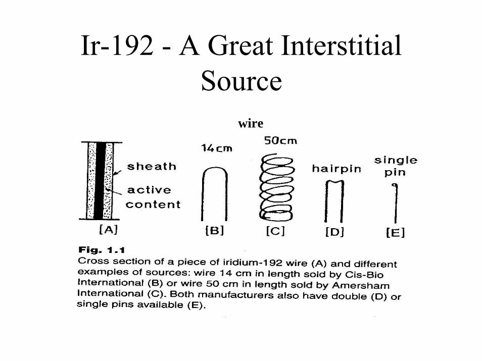
Ir-192 - A Great Interstitial Source
wire

Center-to-center spacing can be user defined.
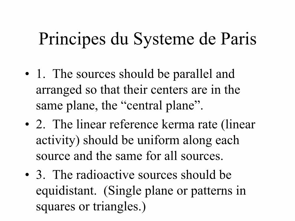
Principes du Systeme de Paris
• 1. The sources should be parallel and arranged so that their centers are in the same plane, the “central plane”.
• 2. The linear reference kerma rate (linear activity) should be uniform along each source and the same for all sources.
• 3. The radioactive sources should be equidistant. (Single plane or patterns in squares or triangles.)

Central Plane and Basal Point
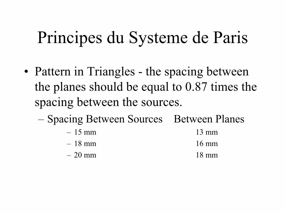
Principes du Systeme de Paris
• Pattern in Triangles - the spacing between the planes should be equal to 0.87 times the spacing between the sources.– Spacing Between Sources Between Planes
– 15 mm 13 mm– 18 mm 16 mm– 20 mm 18 mm
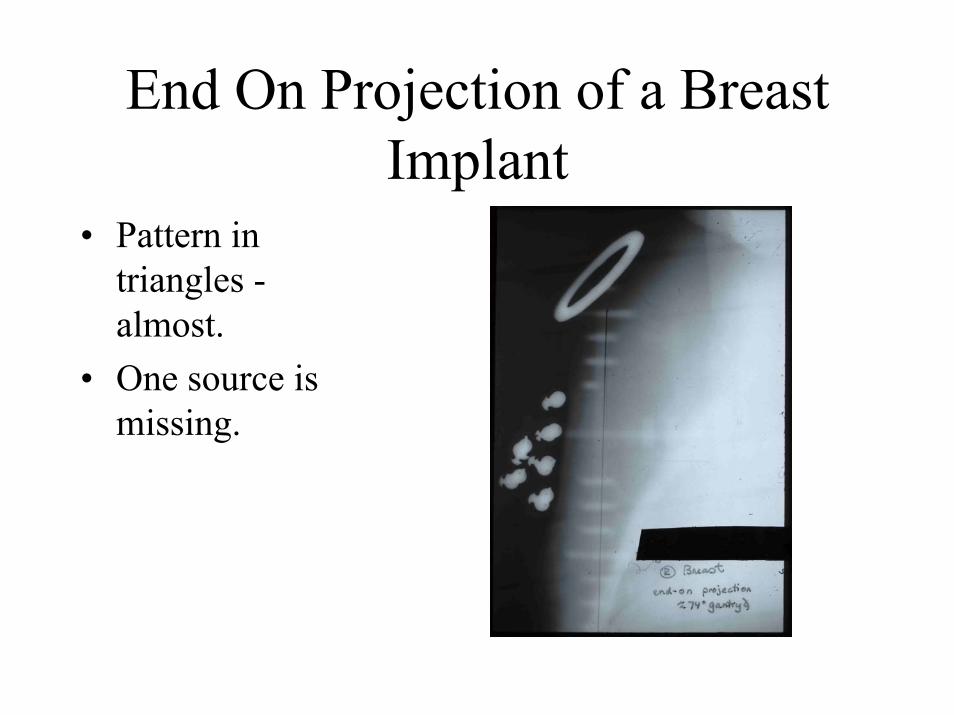
End On Projection of a Breast Implant
• Pattern in triangles -almost.
• One source is missing.

Pattern in Squares
• Hairpins - separation between the legs - 12 mm
Specification de la dose
• Basal dose rate: the arithmetic mean of the minimum dose rate, which is located half-way between the sources in the well defined patterns used in the Paris System.

Location of Basal Dose Rates

Specification de la dose• Reference Isodose - The reference isodose
has a value equal to 85% of the basal dose. This value is based upon clinical experience.
• Treated Volume - The volume surrounded by the 85% isodose surface.
• Hyperdose volume - The volume of the 170% of the basal dose (twice the reference isodose).

Basal Dose, Prescription Dose, Hyperdose
Hyperdose
Prescription dose

Relations previsionnelles
• The method is to carefully evaluate the target volume to be implanted and define its three dimensions.
• The number of source planes to be used depends upon the thickness. If the thickness exceeds 12 mm, there must be 2 source planes.

Predictive Relationships for Equal Length Rectilinear Sources
Pattern TreatedLength/Active Length
TreatedThickness/Spacing
LateralMargin/Spacing
SafetyMargin/Spacing
2 sources 0.7 0.5 0.37
3 or moresources
0.7 0.6 0.33
Squares 0.7 1.55-1.60 0.27
Triangles 0.7 1.3 0.20
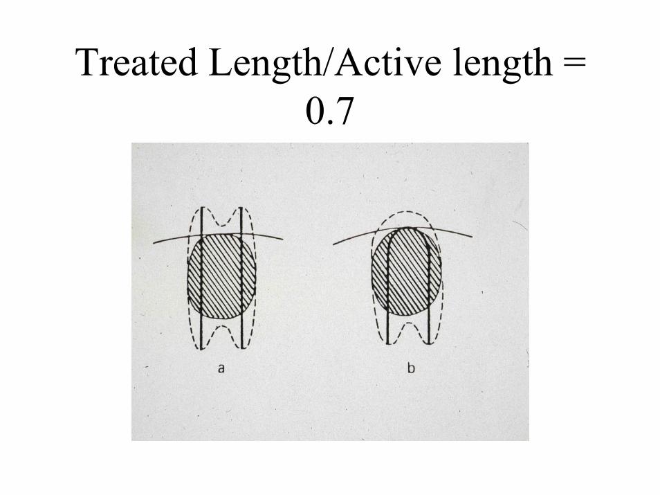
Treated Length/Active length = 0.7

Double Plane - Triangles
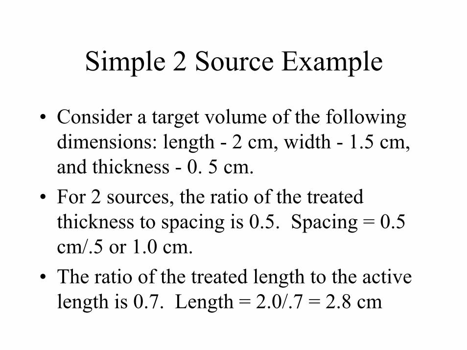
Simple 2 Source Example
• Consider a target volume of the following dimensions: length - 2 cm, width - 1.5 cm, and thickness - 0. 5 cm.
• For 2 sources, the ratio of the treated thickness to spacing is 0.5. Spacing = 0.5 cm/.5 or 1.0 cm.
• The ratio of the treated length to the active length is 0.7. Length = 2.0/.7 = 2.8 cm
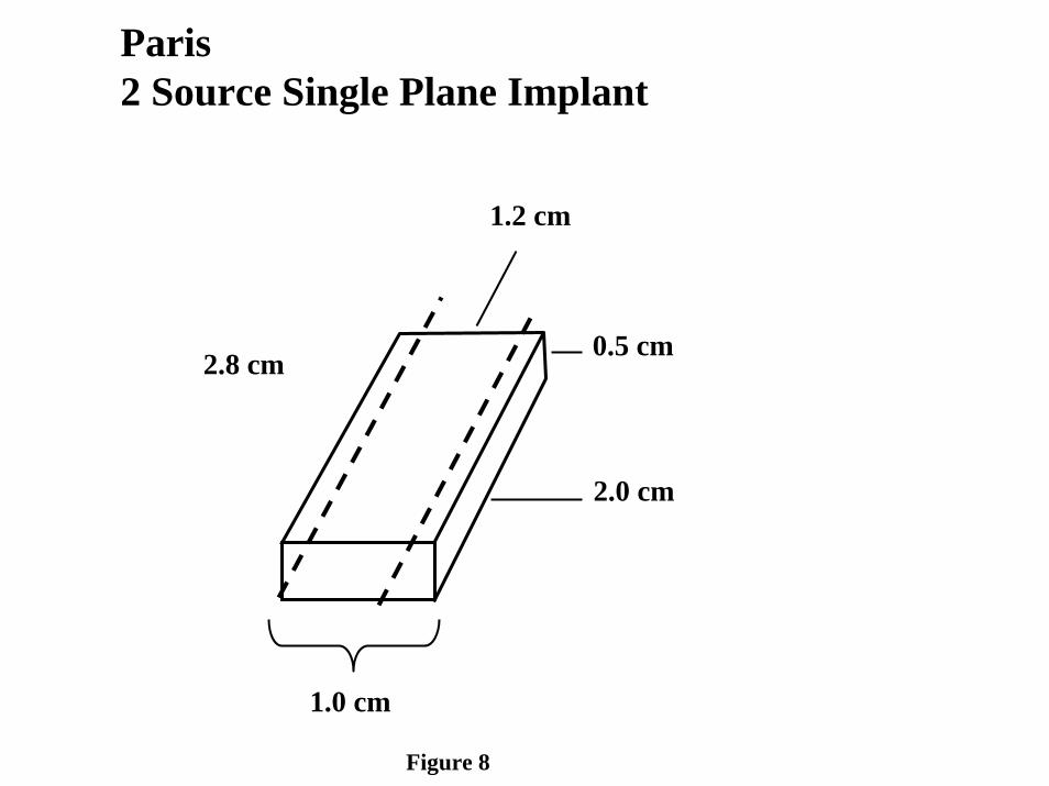
2.8 cm
1.2 cm
1.0 cm
0.5 cm
2.0 cm
Paris2 Source Single Plane Implant
Figure 8
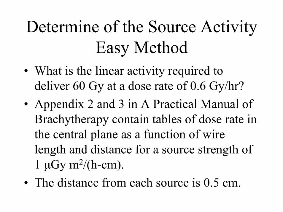
Determine of the Source ActivityEasy Method
• What is the linear activity required to deliver 60 Gy at a dose rate of 0.6 Gy/hr?
• Appendix 2 and 3 in A Practical Manual of Brachytherapy contain tables of dose rate in the central plane as a function of wire length and distance for a source strength of 1 μGy m2/(h-cm).
• The distance from each source is 0.5 cm.

Determine of the Source ActivityEasy Method
• For a 3 cm long source (0.3 mm diameter) at a distance of 5 mm in the central plane, the dose rate is 5.48 cGy/h.
• Thus, the dose rate at the basal point is 10.96 cGy/h.
• The prescription dose rate is 0.85 x 10.96 = 9.3 cGy/h.
• The desired prescription dose rate is 60 cGy/h.

Determine of the Source ActivityEasy Method
• The needed source strength is 1 U/cm * (60/9.3) = 6.45 U/cm
• TG 43 suggests a conversion rate of 4.2 U/mCi.
• 6.45 U/cm/4.2U/mCi = 1.54 mCi/cm• As opposed to wire assume Ir-192 seeds
with 5 mm center-to-center spacing.• 0.77 mCi/seed or .77x4.69/8.25 = 0.44
mgRaeq/seed

2.8 cm
1.2 cm
1.0 cm
0.5 cm
2.0 cm
Paris2 Source Single Plane Implant
Figure 8
60 cGy/hr prescription dose requires a linear activity of 1.54 mCi/cm for wire or a seed activity of 0.44 mg Ra eq when a seed spacing of 5 mm c-to-c.
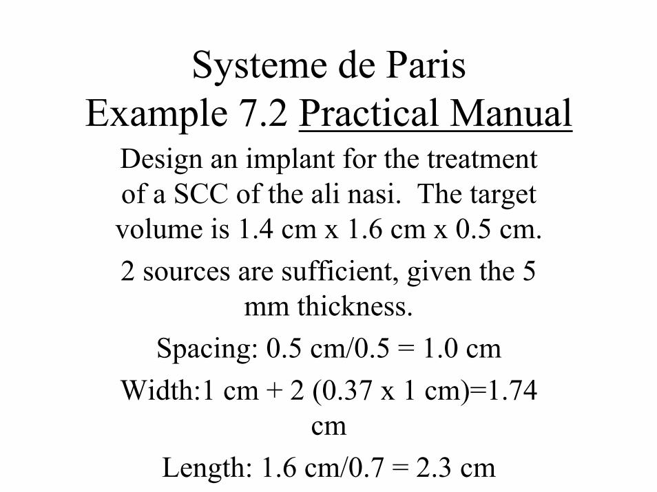
Systeme de ParisExample 7.2 Practical Manual
Design an implant for the treatment of a SCC of the ali nasi. The target volume is 1.4 cm x 1.6 cm x 0.5 cm.2 sources are sufficient, given the 5
mm thickness.Spacing: 0.5 cm/0.5 = 1.0 cm
Width:1 cm + 2 (0.37 x 1 cm)=1.74 cm
Length: 1.6 cm/0.7 = 2.3 cm
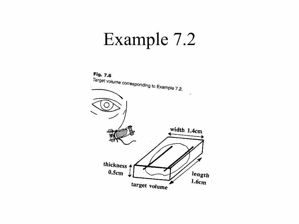
Example 7.2
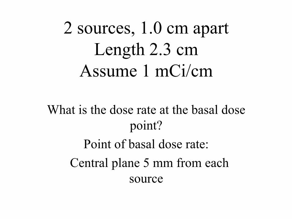
2 sources, 1.0 cm apartLength 2.3 cm
Assume 1 mCi/cm
What is the dose rate at the basal dose point?
Point of basal dose rate:Central plane 5 mm from each
source

Look Up Approach
Distance: 5 mmLength: 2.3 cm
Table: Appendix 2 for 1 U/cm5.1 cGy/h/source = 10.2 cGy/hr
4.2 U/mCiDose rate: 42.8 cGy/h

Simple calculationUnfiltered Line Source
12 t a n2
A lD Rh l h
−Γ ⎛ ⎞ ⎛ ⎞= ⋅ ⋅ ⋅⎜ ⎟ ⎜ ⎟⎝ ⎠ ⎝ ⎠
Where Γ is the dose rate constanth is the perpendicular distance to the center
of the squareA is the activityl is the active length
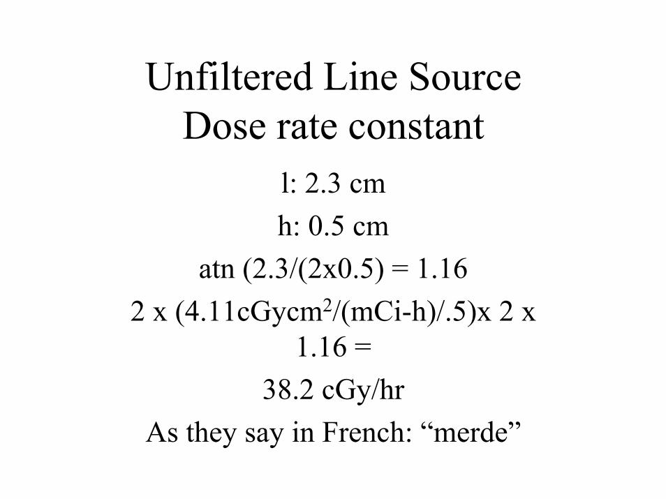
Unfiltered Line SourceDose rate constant
l: 2.3 cmh: 0.5 cm
atn (2.3/(2x0.5) = 1.162 x (4.11cGycm2/(mCi-h)/.5)x 2 x
1.16 =38.2 cGy/hr
As they say in French: “merde”
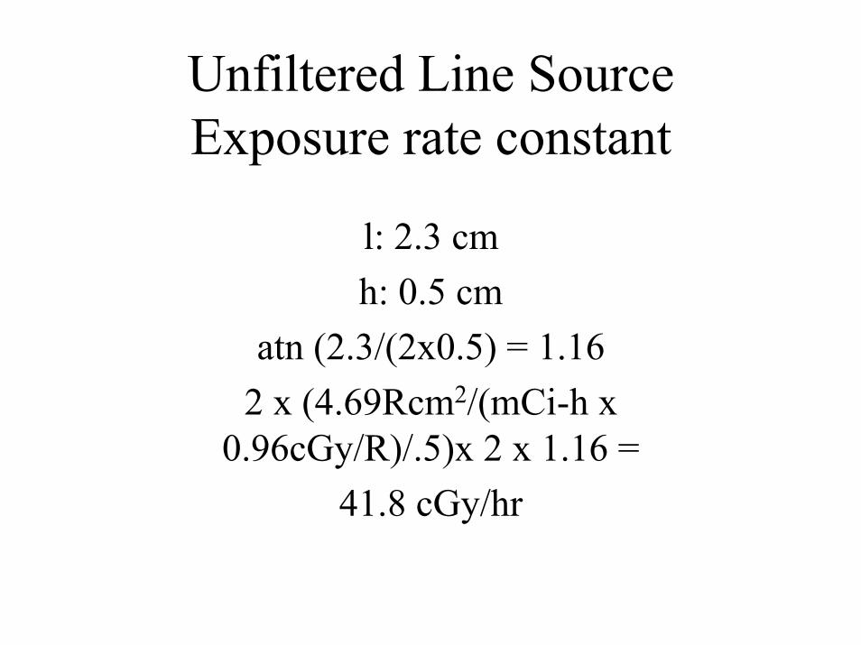
Unfiltered Line SourceExposure rate constant
l: 2.3 cmh: 0.5 cm
atn (2.3/(2x0.5) = 1.162 x (4.69Rcm2/(mCi-h x
0.96cGy/R)/.5)x 2 x 1.16 =41.8 cGy/hr

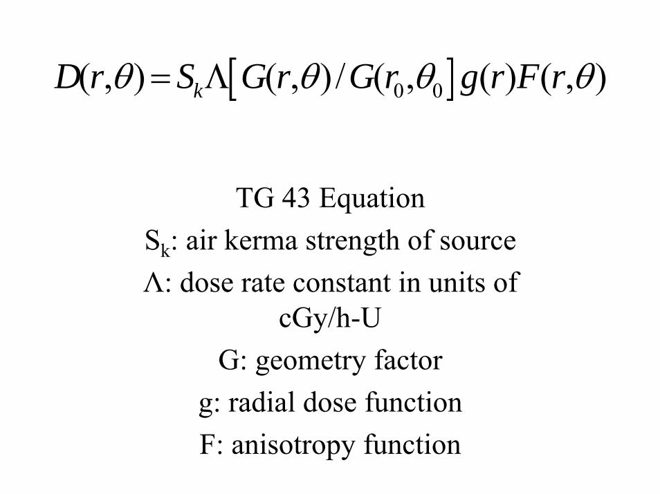
[ ]0 0( , ) ( , ) / ( , ( ) ( , )kD r S G r G r g r F rθ θ θ θ= Λ
TG 43 EquationSk: air kerma strength of sourceΛ: dose rate constant in units of
cGy/h-UG: geometry factor
g: radial dose functionF: anisotropy function
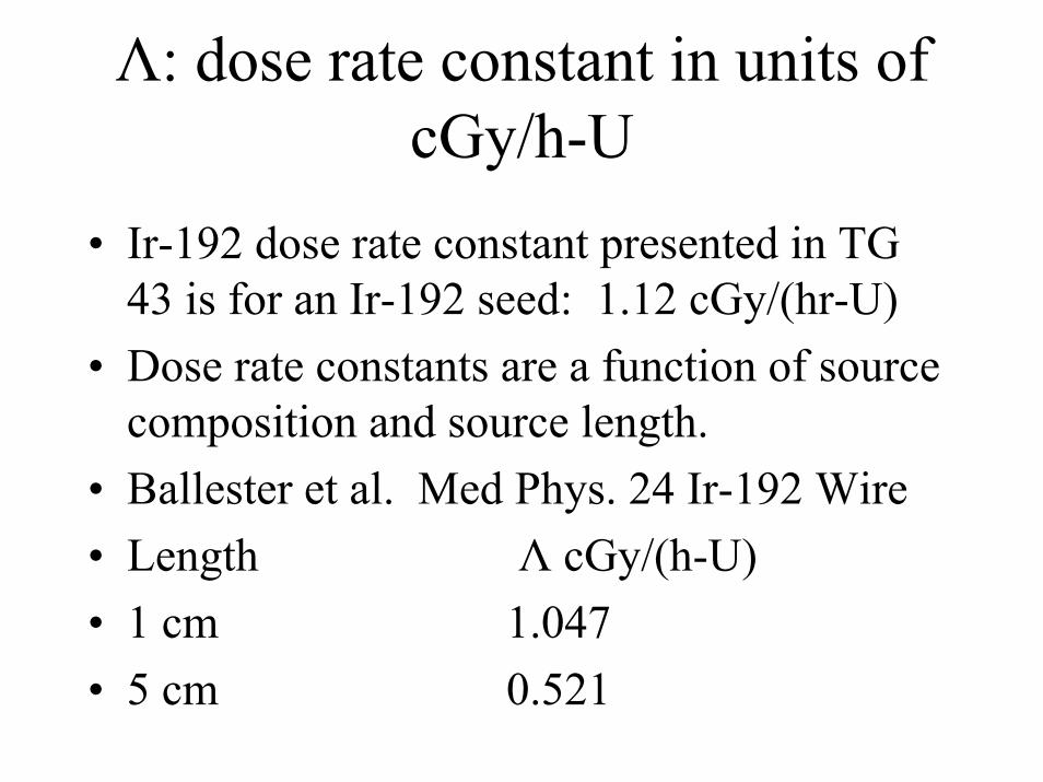
Λ: dose rate constant in units of cGy/h-U
• Ir-192 dose rate constant presented in TG 43 is for an Ir-192 seed: 1.12 cGy/(hr-U)
• Dose rate constants are a function of source composition and source length.
• Ballester et al. Med Phys. 24 Ir-192 Wire• Length Λ cGy/(h-U)• 1 cm 1.047• 5 cm 0.521
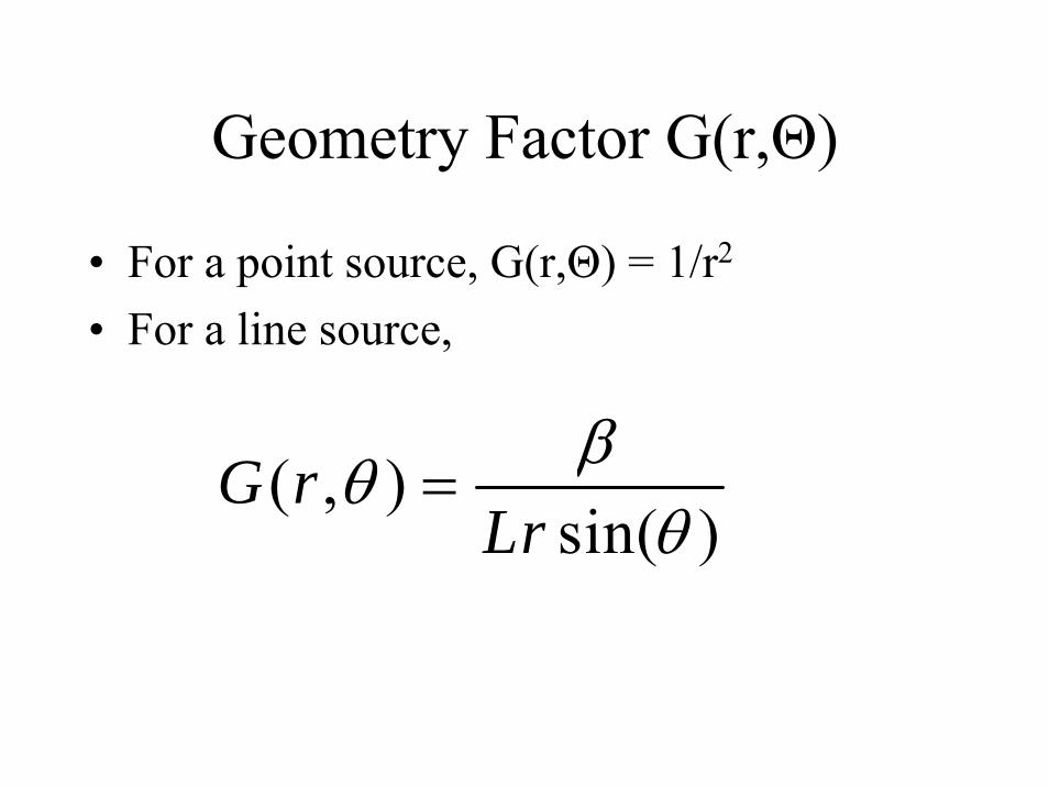
Geometry Factor G(r,Θ)
• For a point source, G(r,Θ) = 1/r2
• For a line source,
( , )sin( )
G rLr
βθθ
=

What is the ratio of geometric factors for a 2.3 cm long source at distances of 0.5 cm and 1.0
cm?If the source was a point source, then
then ratio would be 4.Thus for a line source, a value less
than 4 is expected.
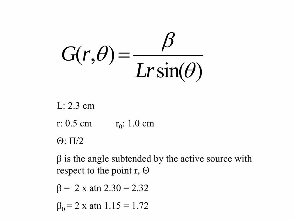
( , )sin( )
G rLr
βθθ
=
L: 2.3 cm
r: 0.5 cm r0: 1.0 cm
Θ: Π/2
β is the angle subtended by the active source with respect to the point r, Θ
β = 2 x atn 2.30 = 2.32
β0 = 2 x atn 1.15 = 1.72
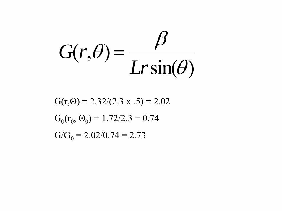
( , )sin( )
G rLr
βθθ
=
G(r,Θ) = 2.32/(2.3 x .5) = 2.02
G0(r0, Θ0) = 1.72/2.3 = 0.74
G/G0 = 2.02/0.74 = 2.73
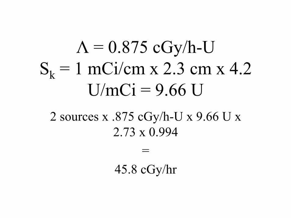
Λ = 0.875 cGy/h-USk = 1 mCi/cm x 2.3 cm x 4.2
U/mCi = 9.66 U2 sources x .875 cGy/h-U x 9.66 U x
2.73 x 0.994 =
45.8 cGy/hr
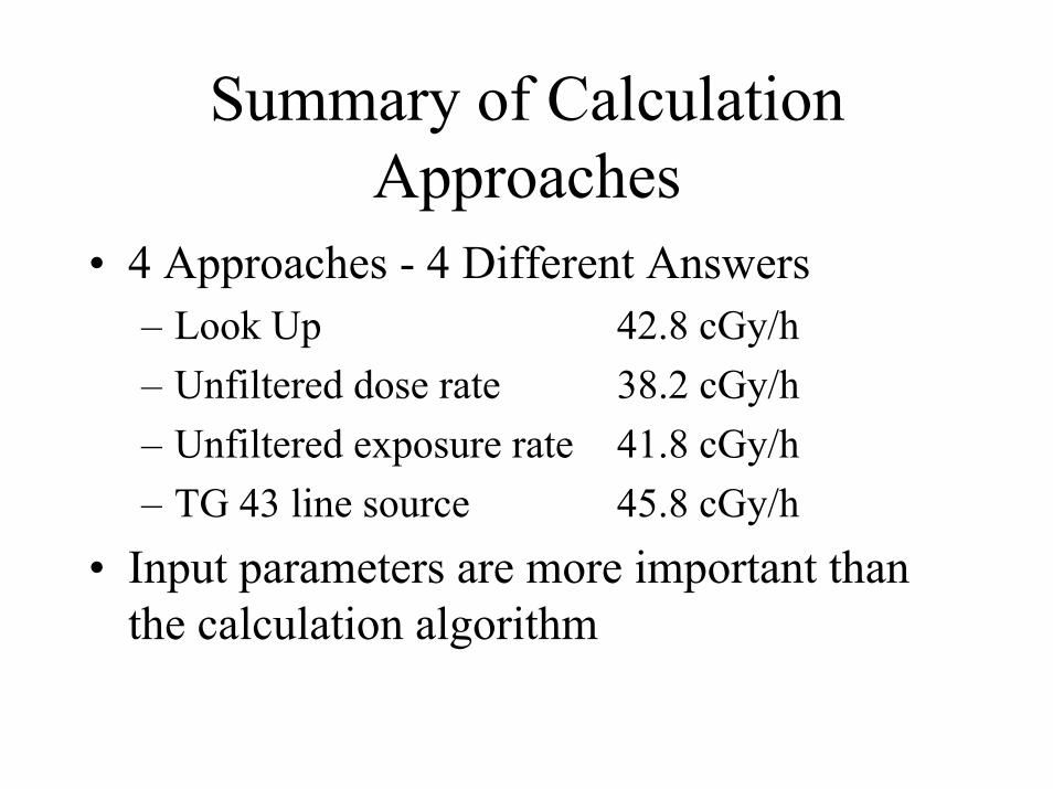
Summary of Calculation Approaches
• 4 Approaches - 4 Different Answers– Look Up 42.8 cGy/h– Unfiltered dose rate 38.2 cGy/h– Unfiltered exposure rate 41.8 cGy/h– TG 43 line source 45.8 cGy/h
• Input parameters are more important than the calculation algorithm

Systeme de ParisExample 8.1 Practical Manual
Design an implant for the treatment of a lateral tongue tumor
corresponding to a volume of 3 cm x 2.5 cm x 1.5 cm.
Hair pins with a separation of 1.2 cm would be used.
This provides a treated thickness of 1.2 cm x 1.55 = 1.9 cm

Example 8.1
A: Anterior Projection B: Lateral Projection

Systeme de ParisExample 8.1 Practical Manual
This would be a pattern in squares with a spacing of 1.2 cm between the
hair pins and a total of 3 hair pins.Treated width: 1.2 cm x 2 +
2(0.27x1.2cm) = 3.0 cmLength: 3 cm/0.8 - 0.6 cm = 3.2 cm(0.6 cm is half the length of the bridge)

Systeme de ParisExample 8.2 Practical Manual
Design an implant for the treatment of a lateral tongue tumor
corresponding to a volume of 3.5 cm x 4.0 cm x 2.5 cm.
The 2.5 cm thickness of the target volume necessitates a spacing of:
2.5 cm/1.55 = 1.6 cmLoops, as opposed to hair pins, would
be used.
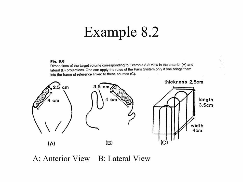
Example 8.2
A: Anterior View B: Lateral View
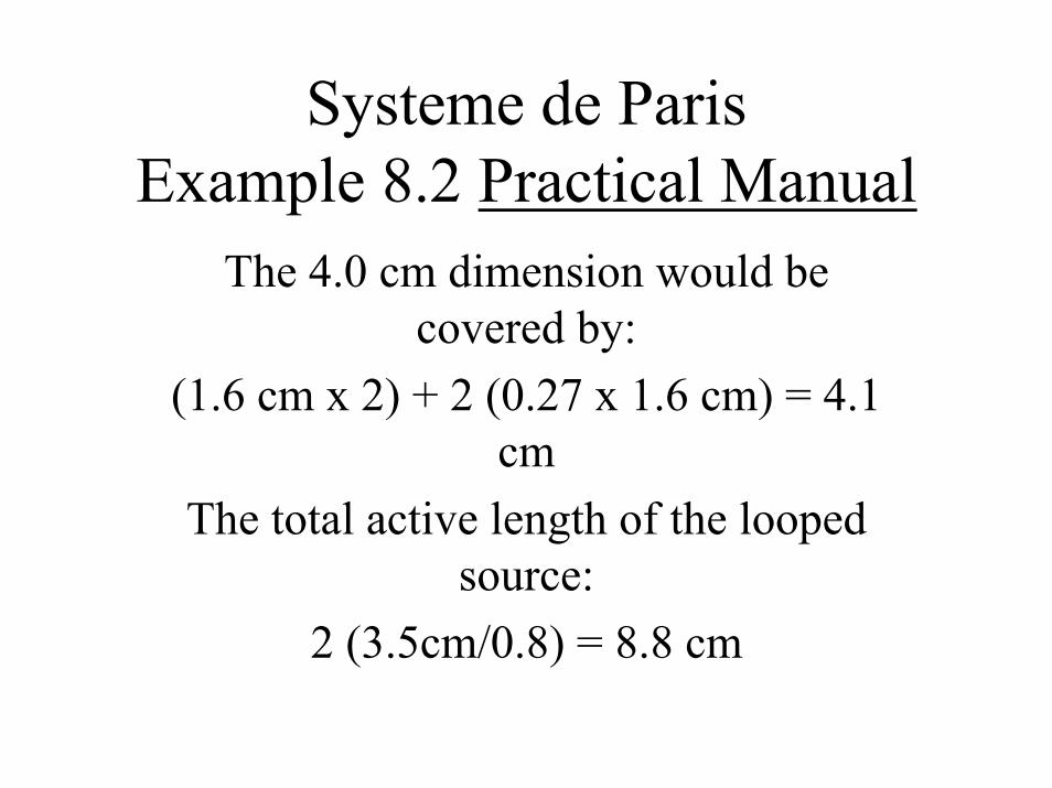
Systeme de ParisExample 8.2 Practical Manual
The 4.0 cm dimension would be covered by:
(1.6 cm x 2) + 2 (0.27 x 1.6 cm) = 4.1 cm
The total active length of the looped source:
2 (3.5cm/0.8) = 8.8 cm
Systeme de ParisExample 9.1 Practical Manual
Design an implant to treat a recurrence in the chest wall following
mastectomy. The target volume measures 6 x 3 x 1 cm.
The largest dimension is 6 cm, so the sources would be implanted
perpendicular to this dimension.

Systeme de ParisExample 9.1 Practical Manual
Active length: 3.0 cm/0.7 = 4.3 cmSource separation: 1cm/0.6 = 1.7 cmLateral margin: 1.7 cm x 0.37 = 0.6
cm4 sources are needed.
Width treated: (3x1.7 cm) + (2x0.6cm) = 6.3 cm

x x x
x
Single Plane Implant
Target Volume6 X 3 X 1 cm3
4 Line Sources4.3cm In Length1.7 cm Separation
Basal Dose Calculation Points
Figure 11
Assuming the linear activity is 1 mCi/cm, what is the dose rate at the central basal point?
[ ]0 0( , ) ( , ) / ( , ( ) ( , )kD r S G r G r g r F rθ θ θ θ= Λ
TG 43 EquationSk: air kerma strength of sourceΛ: dose rate constant in units of
cGy/h-UG: geometry factor
g: radial dose functionF: anisotropy function
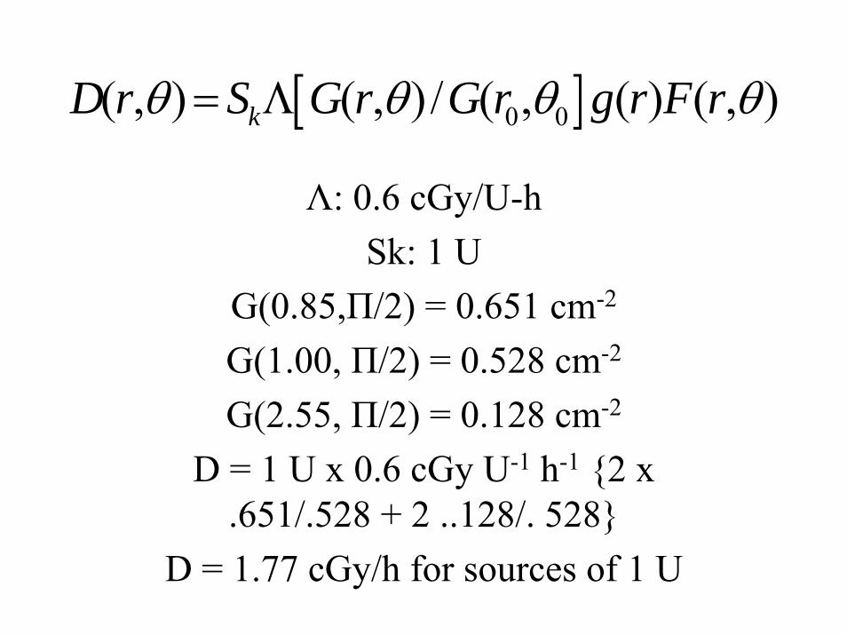
[ ]0 0( , ) ( , ) / ( , ( ) ( , )kD r S G r G r g r F rθ θ θ θ= Λ
Λ: 0.6 cGy/U-hSk: 1 U
G(0.85,Π/2) = 0.651 cm-2
G(1.00, Π/2) = 0.528 cm-2
G(2.55, Π/2) = 0.128 cm-2
D = 1 U x 0.6 cGy U-1 h-1 {2 x .651/.528 + 2 ..128/. 528}
D = 1.77 cGy/h for sources of 1 U

Typical Prescription dose rates are on the order of 60 cGy/h
1.77 cGy/h for 1 U sources 1.77 cGy/h for 0.238 mCi sources
60 cGy/h/.85 = 70 cGy/h Basal dose rate
70 cGy/h/1.77 cGy/h * 0.238 mCi = 9.49 mCi per source
2.2 mCi/cm

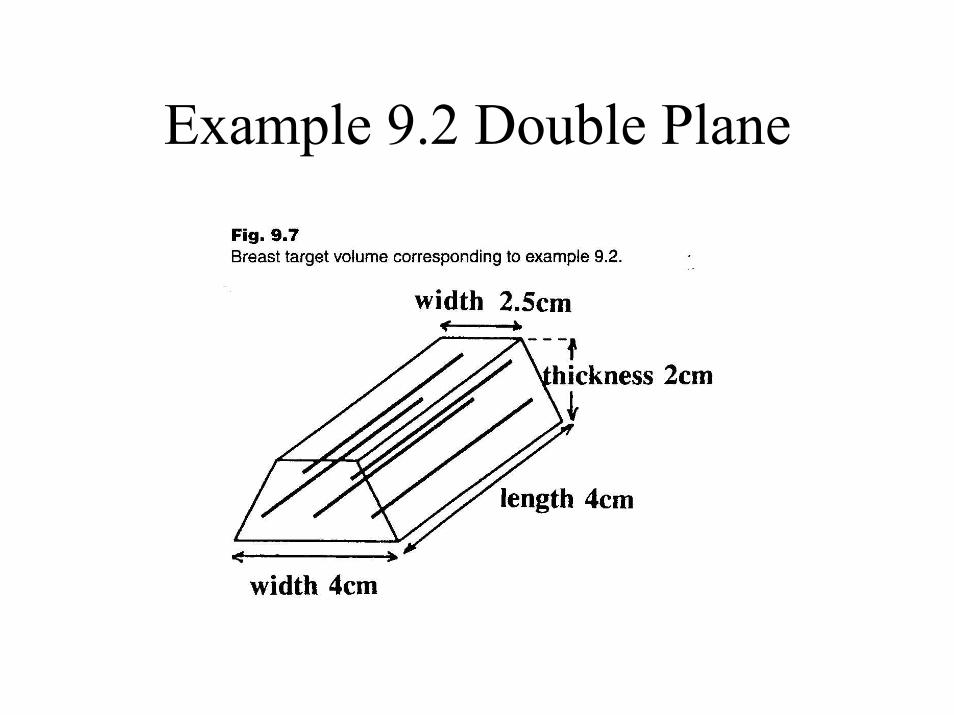
Systeme de ParisExample 9.2 Practical Manual
Design an implant to treat a breast target volume 4 cm in length, 4 cm in width at the base and 2.5 cm in width on the superficial side and 2 cm thick.This would be a two plane implant in
the pattern of triangles.Spacing between the sources:
2.0 cm/1.3 = 1.5 cm
Example 9.2 Double Plane
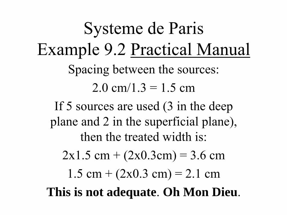
Systeme de ParisExample 9.2 Practical Manual
Spacing between the sources:2.0 cm/1.3 = 1.5 cm
If 5 sources are used (3 in the deep plane and 2 in the superficial plane),
then the treated width is:2x1.5 cm + (2x0.3cm) = 3.6 cm1.5 cm + (2x0.3 cm) = 2.1 cm
This is not adequate. Oh Mon Dieu.
Systeme de ParisExample 9.2 Practical Manual
However, if the spacing is 1.8 cm, which would result in a slightly larger thickness being treated, 1.8 cm x 1.3 = 2.3 cm, and the widths treated are:
2 x 1.8 + (2 x 0.36 cm) = 4.3 cm1.8 + (2 x 0.36 cm) = 2.5 cm
Length: 4 cm/0.7 cm = 5.7 cm

Paris System Summary• Once the target volume is defined, the
number, the source pattern, and the source spacing are easily determined.
• Prescription dose: encompasses the target volume.
• Sources < 3 to 4 cm Spacing between 0.8 to 1.5 cm
• Sources > 4 cm Spacing < 2.2 cm• Simple patterns: line, squares, triangle
Paris System
• Product of both oncologists and physicists.• To plan an implant, the oncologist must
define a target volume.• The Paris System lead to a Stepping Source
Dosimetry System (SSDS) for HDR.

Comparison of Paris and SSDS
• There is a nice article in an obscure reference, namely:
• Comparing the Stepping Source Dosimetry System and the Paris System using Volume-Dose Histograms of Breast Implants by R. van derLaarse and T. P. E. Prins
• Brachytherapy from Radium to Optimization, published by Nucletron and edited by Mould, Battermann, Martinez, and Speiser
Stepping Source Dosimetry System
• Dose points are placed midway between the catheters, not only in the central plane but along all catheters.
• Dwell times are optimized such that the same dose is delivered to all dose points. Consequently the dwell times in the outer ends of the catheters are increased substantially.
• Thus the dwell positions are now inside the target volume.

Solid Line: SSDS Dashed Line: Paris System
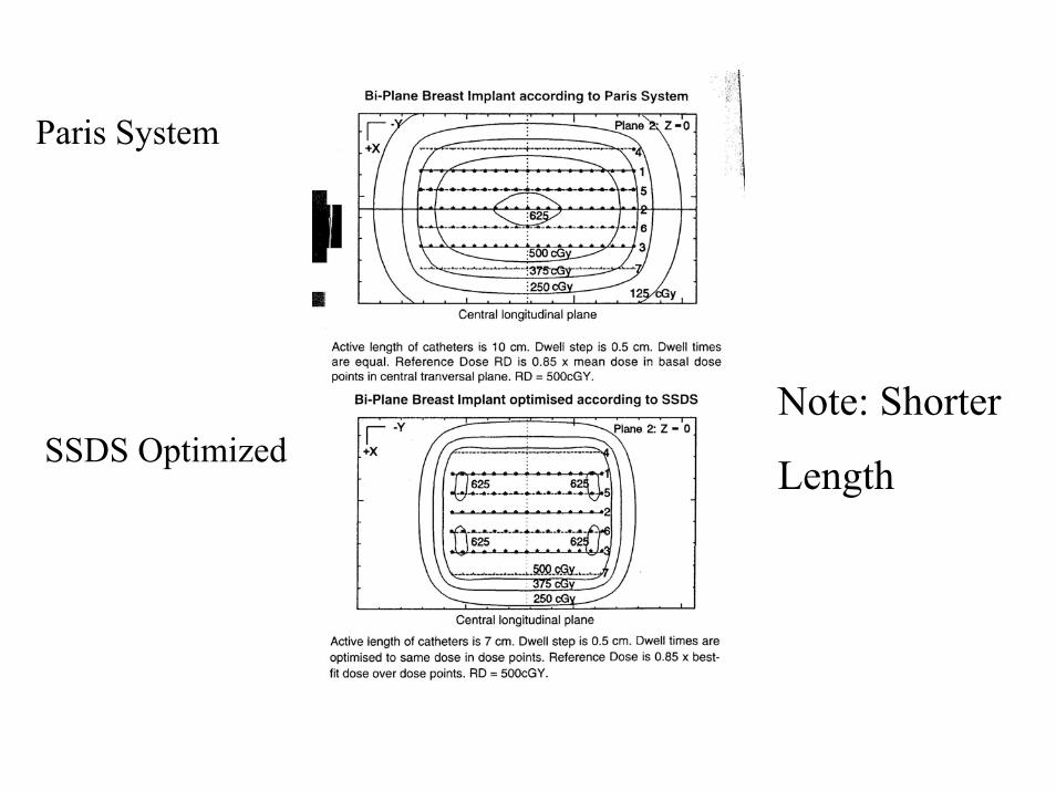
Paris System
SSDS OptimizedNote: Shorter
Length

Le Trocadero - Palais de ChaillotThe Trocadero area, made up of the Place du Trocadero and terraced gardens, is dominated by the Palais de Chaillot. The central terrace between its two wings has been kept clear, forming a perfect frame for the Eiffel Tower beyond.
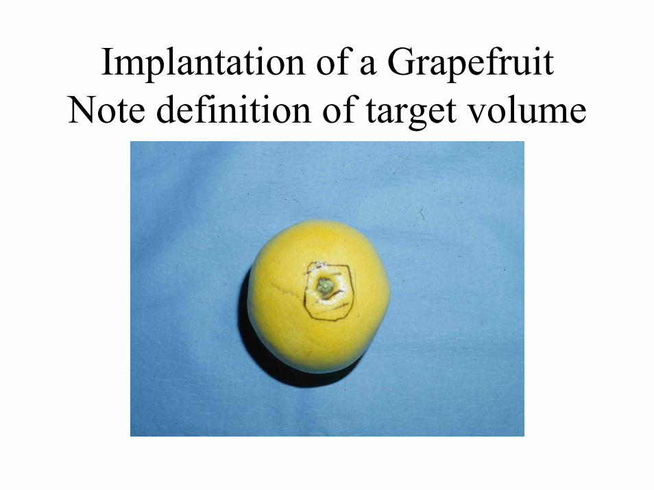
Implantation of a GrapefruitNote definition of target volume
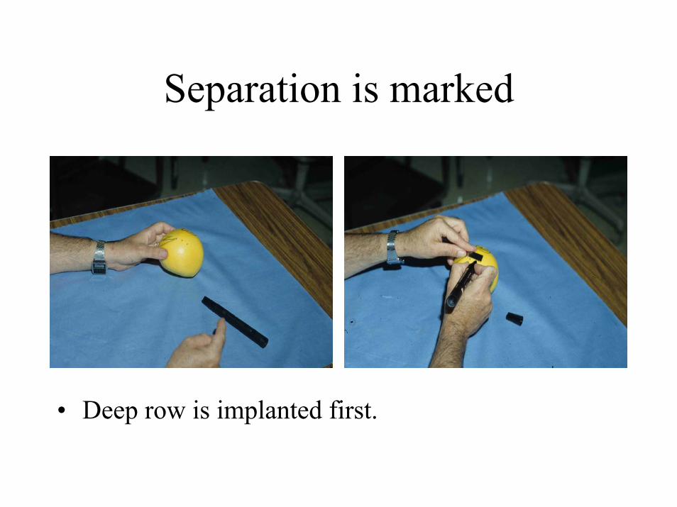
Separation is marked
• Deep row is implanted first.