paras efm operational manual - krantimeters.comkrantimeters.com/pdf/paras-efm-operational.pdf ·...
TRANSCRIPT
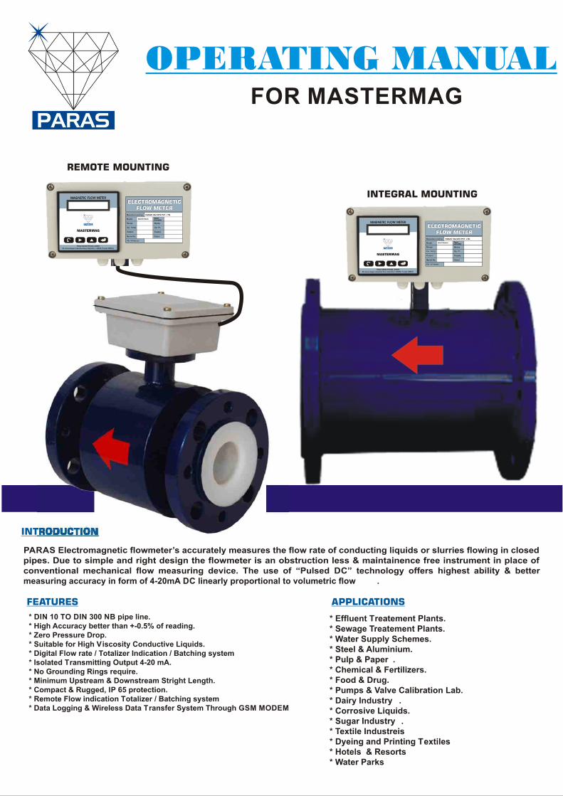
PARAS Electromagnetic flowmeter’s accurately measures the flow rate of conducting liquids or slurries flowing in closedpipes. Due to simple and right design the flowmeter is an obstruction less & maintainence free instrument in place ofconventional mechanical flow measuring device. The use of “Pulsed DC” technology offers highest ability & bettermeasuring accuracy in form of 4-20mA DC linearly proportional to volumetric flow .
* Effluent Treatement Plants. * Sewage Treatement Plants. * Water Supply Schemes. * Steel & Aluminium. * Pulp & Paper . * Chemical & Fertilizers. * Food & Drug. * Pumps & Valve Calibration Lab. * Dairy Industry . * Corrosive Liquids. * Sugar Industry . * Textile Industreis* Dyeing and Printing Textiles* Hotels & Resorts* Water Parks
* DIN 10 TO DIN 300 NB pipe line. * High Accuracy better than +-0.5% of reading. * Zero Pressure Drop. * Suitable for High Viscosity Conductive Liquids. * Digital Flow rate / Totalizer Indication / Batching system * Isolated Transmitting Output 4-20 mA. * No Grounding Rings require. * Minimum Upstream & Downstream Stright Length. * Compact & Rugged, IP 65 protection. * Remote Flow indication Totalizer / Batching system* Data Logging & Wireless Data Transfer System Through GSM MODEM
OPERATING MANUALFOR MASTERMAG
ADVANCED FEATURES
GSM : FLOW MONITORING THROUGH MOBILE VIA SMS
Email : [email protected]
Manufactured by : Users
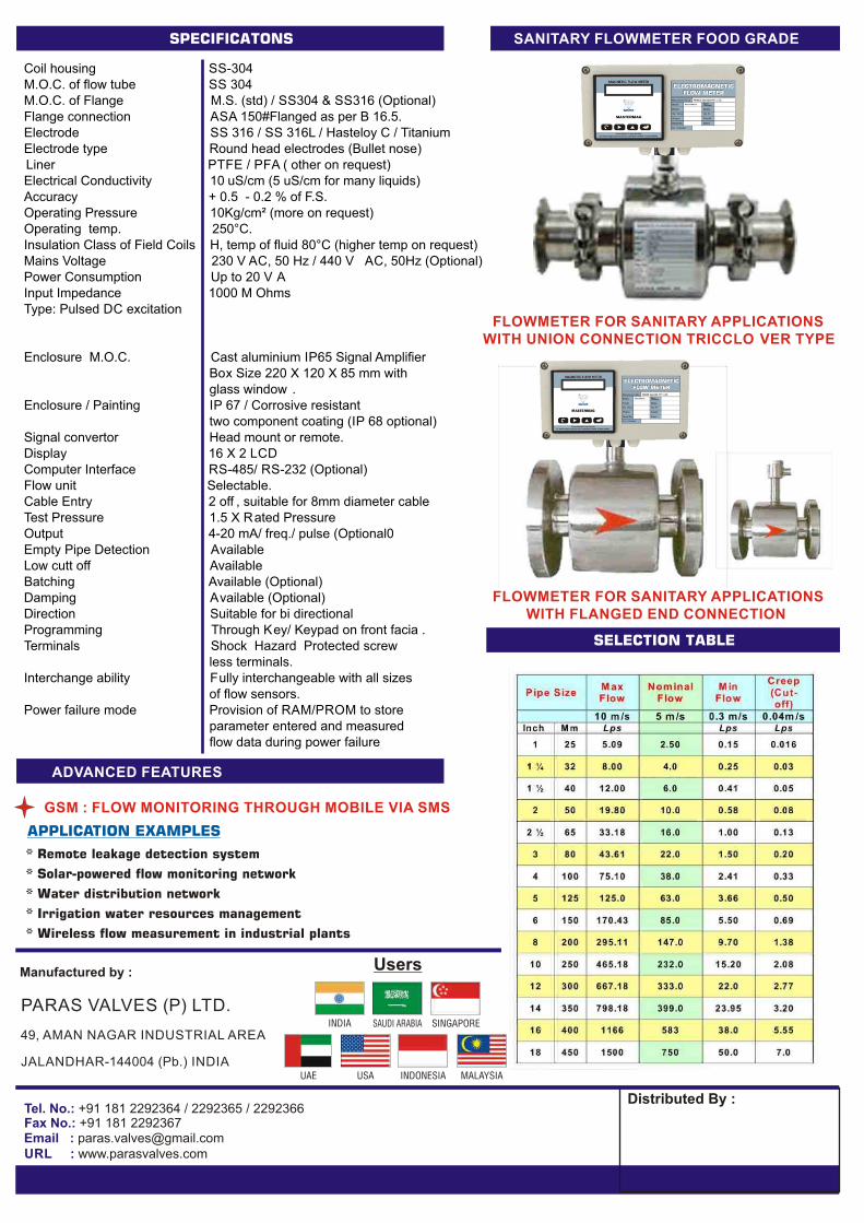
SANITARY FLOWMETER FOOD GRADE
FLOWMETER FOR SANITARY APPLICATIONS WITH UNION CONNECTION TRICCLO VER TYPE
FLOWMETER FOR SANITARY APPLICATIONS WITH FLANGED END CONNECTION
Coil housing SS-304M.O.C. of flow tube SS 304M.O.C. of Flange M.S. (std) / SS304 & SS316 (Optional)Flange connection ASA 150#Flanged as per B 16.5.Electrode SS 316 / SS 316L / Hasteloy C / TitaniumElectrode type Round head electrodes (Bullet nose)Liner PTFE / PF A ( other on request)Electrical Conductivity 10 uS/cm (5 uS/cm for many liquids)Accuracy + 0.5 - 0.2 % of F.S.Operating Pressure 10Kg/cm² (more on request)Operating temp. 250°C.Insulation Class of Field Coils H, temp of fluid 80°C (higher temp on request) Mains Voltage 230 V AC, 50 Hz / 440 V AC, 50Hz (Optional)Power Consumption Up to 20 V AInput Impedance 1000 M OhmsType: Pulsed DC excitation
Enclosure M.O.C. Cast aluminium IP65 Signal Amplifier Box Size 220 X 120 X 85 mm with glass window . Enclosure / Painting IP 67 / Corrosive resistant two component coating (IP 68 optional) Signal convertor Head mount or remote.Display 16 X 2 LCDComputer Interface RS-485/ RS-232 (Optional)Flow unit Selectable.Cable Entry 2 off , suitable for 8mm diameter cableTest Pressure 1.5 X Rated PressureOutput 4-20 mA/ freq./ pulse (Optional0Empty Pipe Detection AvailableLow cutt off AvailableBatching Available (Optional)Damping Available (Optional)Direction Suitable for bi directionalProgramming Through Key/ Keypad on front facia .Terminals Shock Hazard Protected screw less terminals.Interchange ability Fully interchangeable with all sizes of flow sensors.Power failure mode Provision of RAM/PROM to store parameter entered and measured flow data during power failure
PARAS VALVES (P) LTD.
49, AMAN NAGAR INDUSTRIAL AREA
JALANDHAR-144004 (Pb.) INDIA
Tel. No.: +91 181 2292364 / 2292365 / 2292366Fax No.: +91 181 2292367
URL : www.parasvalves.com
Magnetic Flow-meter User's Guide: (Model : MASTERMAG)
Features:
1.Accuracy Specification: 1.0 % (standard), 0.5% (Optional)2.Empty pipe detection.3.Highly stable reading with fast response time.4.Wide operating range.5.Head Mount display.6.Faster update rate.7.Low flow cut-off option.8.Measures flow in both directions.9.Blue LCD with white character, gives better readability.
10.4-20 mA out put.11.Modbus over Rs 232/ RS 485.
Optional features:
1.Pulse/Freq output.2.Remote enable/disable of totalizer.3.Positive + Negative- totalizer option.4.Relay output for batching application.
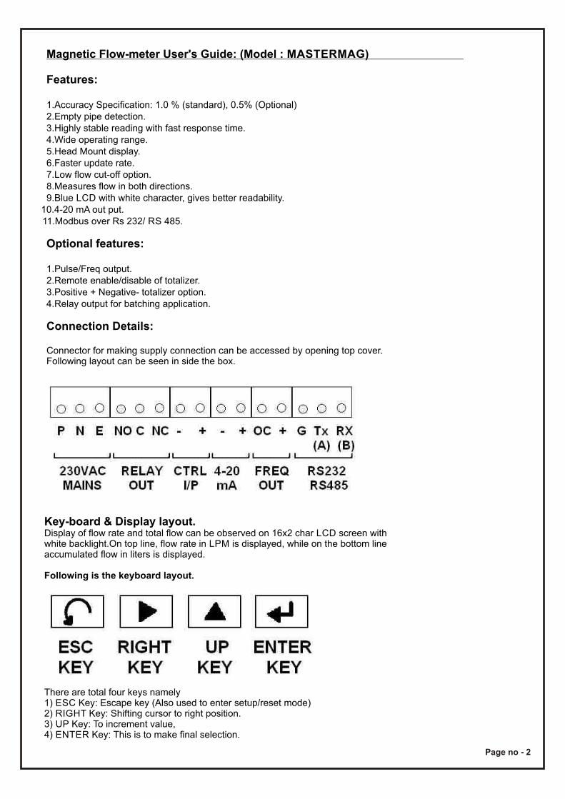
Connection Details:
Connector for making supply connection can be accessed by opening top cover.Following layout can be seen in side the box.
Key-board & Display layout.Display of flow rate and total flow can be observed on 16x2 char LCD screen with white backlight.On top line, flow rate in LPM is displayed, while on the bottom line accumulated flow in liters is displayed.
Following is the keyboard layout.
There are total four keys namely1) ESC Key: Escape key (Also used to enter setup/reset mode)2) RIGHT Key: Shifting cursor to right position.3) UP Key: To increment value,4) ENTER Key: This is to make final selection.
Page no - 2
Modes of operationsThere are four different modes of operation for this magnetic flow-meter, they are1)Normal mode2)Setup mode (Password protected).1)Reset mode (Password protected).2)Time Constant Mode (Password protected)3)Communication mode.4)Modbus RTU Mode5)4-20 mA Output Mode6)Flow Unit Mode:-7)K-Factor Setting (This mode can be enabled in Setup Mode).8)Password reset mode (default password is 1234).
Setup mode:
1. Press “ESC” key to enter setup mode. Message “SET UP MODE” will be displayed on lcd.2.Now press “ENT” key to select setup mode.3.If “SET UP” Mode is selected by “ENT” key, it will ask for password.4.Enter password using “RIGHT” and “UP” key, press “ENT” when done.5.Now display will show first parameter of setup mode.6.One can go to next parameter using “ENT” key edit parameter using “UP” and “RIGHT” keys. When done editing press “ENT” key to go to the next parameter.
Setup parameters will appear in following sequence.
1) Low Cut off: 0010.0: Low flow cut off *.2) Disp. K Factor: No, If YES K-Factor entry will be displayed in Modes of operation. **
*: If actual flow rate goes below low cutoff value, display will show zero flow.It is recommended to set low flow cutoff value to around 1% of span.**: Please note that Wrong entry of K-Factor will change the overall accuracy of your flow meter. So it is desired that this value is not changed before consulting dealer or manufacturer.3) Flow direction: From UP key you can change forward or reverse direction.4) Display format. : You can four type of display format as bellow from this function by pressing UP key. a) 1: Flow 2: Total. That means upper line of display is flow rate & lower line is total qty. b) 1 Total 2: flow. That means upper line of display is total qty. & lower line is flow rate. c) 1 Flow 2 None. That means only flow rate displayed on upper line. d) 1 Total 2: Flow. That means only total qty. displayed on upper line.
In normal mode of operation, mag-flow will display flow rate in LPM and accumulated flow in Liters (i.e. totalizer), this mode if default up on power on.User can reset totalizer in reset mode.Remember that RESET and SETUP modes are password protected and password for both is same. (Initial password is “1234”).User can change password to any other 4 digit value in password reset mode.Time constant settings are provided to user if reading of flow is unstable due to heavily noisy flow. (Time constant setting can be set to 1, 2, 4, 8, 16, 32, 64 and 128). For most applications default values are good enough (default setting is 64).K-Factor is constant factor of flow tube. This factor should not be altered by user without consulting dealer/manufacture. K-Factor only needs to vary in case of converter circuit is replaced. Due to any reason if circuit is needed to change, one can enter the K-Factor value mentioned on the tag to new circuit of converter. This is provided so that end user may not need to recalibrate the flow meter (This is the unique feature we provide, in case of other manufacturers you may have to send the entire unit to the factory for recalibration in case of circuit repair or replacement. K-Factor setting is hidden, and can be made visible using setup mode.
Page no - 3
Reset Mode:
Following is the sequence for resetting totalizer data.
1. Press “ESC” Key, Display will indicate “SETUP MODE”.2. Now press “UP” key to select “RESET MODE”.3. Press “ENT” key to enter into “RESET MODE”4. Now password needed to enter. Enter password using “UP” and “RIGHT” key and press “ENT” key.5. Now it will reconfirm to clear totalizer data or not. i.e. 'Reset total: No'will be displayed.6. Now using “UP” key select “YES” and press “ENT” key and now totalizer data is cleared.7. For a brief time a message “WAIT” will be displayed and instrument will enter into normal operating condition.
Time Constant Mode:
1. Press “ESC” key and message “SET UP MODE” will be displayed on lcd.2. Now press “UP” key until you see “TIME CONSTANT”.3. When “Time Constant” is displayed, press “ENT” key to select Time Constant mode.4. Enter password using “UP” and “RIGHT” keys and press “ENT” key again.5. There are two parameters in this mode 1)mAverage Counter. 2) Diff. Count : 0020.06. Once password is entered, you will be asked to modify “mAverage Counter”, in bottom line value will be displayed for this counter. Default value is “64”.7. Using “UP” key, value can be changed, if you don't want to change value simply press “ENT” key to go to the next parameter.8. Allow value for “mAverage Counter” is 1, 2, 4, 8, 16, 32, 64 and 128. Higher value shall be selected for noisy flow environment. Higher the value slower the response of flow meter. Note the default value of 64 is good enough for most of the application with good stability and acceptable response time.9. By pressing “ENT” key one can go the next parameter under “Time Constant” mode. i.e. Diff.Count : 0020.0. This value should be between 1% and 5% of maximum flow rate. Making this value 0000.0 will make flow reading little unstable. Entering very high value will slow down the response of flow meter.10. Press “ENT” key when done to enter into normal operating mode.11. Please note that factory set values is good enough for most of the applications.
Communication Mode:
1. Press “ESC” key and message “SET UP MODE” will be displayed on lcd.2. Now press “UP” key until you see “Communication”.3. Press Enter key to enter in Communication mode and Enter Password.4. There are three protocol selections in this mode.5. 1) F1 Protocol. 2) Modbus Protocol. 3) Sens I D Protocol. Select it from UP key.6. After selection of protocol press ENTER key.
st7. 1 comes baudrate setting. It can be changed by UP key.nd
8. 2 comes Device ID setting. It can be changed by UP key.rd
9. 3 comes parity setting. It can be changed by UP key.10.Then press ENTER to save setting.
Page no - 4
Flow Unit Mode: 1. Press enter key to Enter in Flow Unit Mode and Enter Password.2. 1st comes Flow Unit for Flow Rate and Total. it can be changed by p2 key.3. Units: 1.Lt/Hr 2.m3/Hr 3.ft3/Hr 4.Gl/Hr 5.Lt/Mn 6.m3/Mn 7.ft3/Mn 8.Gl/Mn 9.Lt/Sc 10.m3/Sc 11.ft3/Sc 12.Gl/Sc
4. 2nd comes Line Size Setting. It can be changed by UP key. Note that Decimal Point Position is taken automatically depending upon Flow Unit & line Size selected.
K-Factor Mode:
Consult dealer or manufacture before modifying K-Factor.
1. First go “Setup Mode” and enable K-Factor display.2. Now Press “ESC” Key, Display will indicate “SETUP MODE”.3. Now press “UP” key, “RESET MODE” will be displayed.4. Press “UP” key again and display will indicate “K-Factor”5. Press “ENT” key to enter into “K-FACTOR Mode”6. Enter password using “UP” and “RIGHT” key and press “ENT” key.7. Seven plus five digit value of K-Factor will be displayed now. i.e. 0000000.00000. Not down older value before making any change. 8. Now using “UP” and “RIGHT” keys enter the desired value of K-Factor. 9. Press “ENT” key when done and instrument will enter into normal operating condition.
Changing Password:
Following is the sequence for change password.
1.Turn off the power supply to flow meter.2.Press “ESC” and “RIGHT” keys together.3.While pressing both keys, power up the flow-meter.4.Display will show message for entering new password.5.Using “UP” and “RIGHT” keys enter new password.6.When done, press “ENT” key to go to normal mode of operation.
Notes on Installation:
1) One should observe following precautions at the time of magnetic flow meter.2) Earthling plates provided on both side of flanges shall not be removed.3) Install mag-flow using at least 4 pair of screw bolt on both flanges.4) During installation, apply equal torque on each screw-bolt and tighten all four bolts one by one.5) Make sure there is no leakage of liquid from both ends. Due to leakage internal electrodes may get shorted causing variations in displayed reading.
Page no - 5
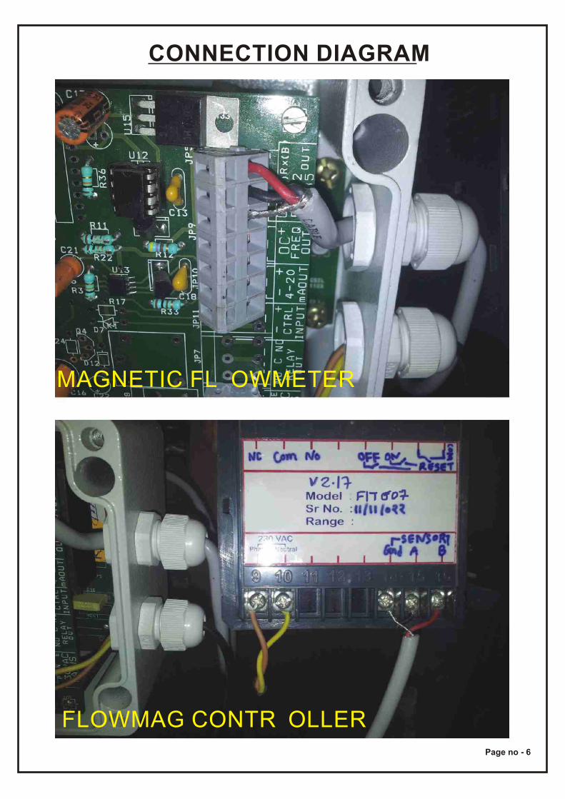
CONNECTION DIAGRAM
FLOWMAG CONTR OLLER
MAGNETIC FL OWMETER
Page no - 6