parallel three-dimensional mesh generation
TRANSCRIPT
Pergamon Computing Srstems in Engineering. Vol. 5, No. 4~6. pp. 311 323, 1994
Copyright ~" 1995 Elsevier Science Ltd 0956-0521(94)00015-8 Printed in Great Britain. All rights reserved
0956-0521/94 $7.00 + 0.00
P A R A L L E L T H R E E - D I M E N S I O N A L MESH G E N E R A T I O N
HUGUES L. DE COUGNY. MARK S. SHEPHARD and CAN OZTURAN
Scientific Computation Research Center, Rensselaer Polytechnic Institute, Troy, NY 12180-3590, U.S.A.
Abstract This paper discusses the development of an automatic mesh generation technique designed to effectively operate on multiple instruction, multiple data (MIMD) parallel computers. The paper first provides an overview of a new octree-based procedure designed for the parallel generation of meshes of large numbers of elements directly from solid model representations. The techniques required to implement such a procedure using message passing on MIMD computers are emphasized. Technical issues considered include the region meshing algorithm, multiple octant migration and incremental load balancing.
INTRODUCTION
The development of automatic grid generation tech- niques for complex three-dimensional configurations has been an active area of research for over a decade. ~'2 The introduction of these mesh generation procedures has removed a major bottleneck in the application of finite element and finite volume analysis techniques. The introduction of scalable parallel computers is allowing the solution of ever larger models. It is now common to see grids of several million elements solved on these computers, with the ability to solve on grids of tens or hundreds of millions of elements coming in the very near future. As mesh sizes become this large, the process of mesh generating on a serial computer becomes problematic both in the terms of time and storage. This paper discusses efforts to address this problem by the development of a parallel mesh gener- ation procedure that will operate on the same com- puter as the parallel analysis procedures.
With recent advances in the efficiency of automatic mesh generators which create well over two million elements per hour on a modest workstation, 3 one may question the need for the parallel generation of meshes. The obvious answer is that as the problem size grows, the solution process on parallel computers will continue to scale by the addition of more processors. However, mesh generation on a single process will not scale, therefore becoming the compu- tational bottleneck. A second critical reason for the parallel mesh generation is the impracticality of providing sufficient memory and high speed com- munications on a single processor to be able to store the whole mesh, and then distribute it onto the processors of the parallel machine on which the solution process will be performed. The memory problem is addressed by the distribution of the generation over a number of processors, each of which stores its portion of the mesh. The communi-
cation problem is eliminated, or at least greatly reduced, since the mesh is distributed over all, or at least some fraction of the processors on which the solution process is to be performed.
Highly efficient parallel algorithms require a bal- ance of work load among the processors while main- taining interprocessor communicat ion at a minimum. Key to determining and distributing the work load and controlling communications is knowledge of the structure of the calculations and communications. In the finite element analysis process, the mesh and its connectivity naturally provide the required structure. The ability to maintain efficiency is compromised when the structure and, therefore, work load and communications is altered as is the case in parallel adaptive finite element analysis. 4 Parallel mesh gener- ation is even more complex to effectively control since the only structure known at the start of the process is that of the geometric model which has no dis- cernible relationship to the work load needed to generate the mesh. On the other hand, the more useful structure to discern work load and control communicat ions is the mesh which is only fully known at the end of the process.
The lack of initial structure and ability to accu- rately predict work load at the beginning of the meshing process underlies the selection of algorithmic procedures in the parallel mesh generation procedure presented here. In particular, the procedure employs an octree decomposit ion of the domain to control the meshing process. The octree structure supports the distribution of computational effort to processors and communicat ion between processors as it evolves during the meshing process. Since the octree evolves during the meshing process and the work load associ- ated with each octree cell is not simple to predict early in the process, the second key aspect of the procedure is the ability to incrementally re-balance the work load in parallel during the process.
311
312 HUGUES L. DE COUGNY et al.
The next section considers efforts to date on the parallelization of automatic mesh generation and outlines initial efforts to parallelize the finite octree mesh generator. 5 These results indicate the complexi- ties of efficient parallel mesh generation and the desire to define a new procedure more specifically oriented to parallel processing. The basic section that follows describes the specific operations carried out in the major step of region meshing in the new mesh generation procedure.
The two sections which follow consider the parallel implementation of that mesh generation step. One section discusses the basic tools, in terms of both data structures and parallel operations, needed to support the mesh generator. The other section discusses the progress to date on the parallelization of that mesh generation step.
BACKGROUND AND MESHING APPROACH
To date there has only been limited attention given to the creation of parallel automatic mesh generation algorithms. One reason for this is that it is only recently that mesh sizes have become large enough to make serial automatic mesh generation a potential bottleneck. A second reason is that the unstructured nature of an automatic mesh generation algorithm requires the use of MIMD constructs to develop an acceptable parallel algorithm. The current generation of MIMD parallel computers, with adequate per- processor memory and associated message passing software, now provides a scalable environment to support this need.
L6hner e t a l . 6 have parallelized an advancing front procedure which starts from a pre-triangulated model boundary. The approach taken is to subdivide the domain (with the help of a background grid) and distribute the sub-domains to different processors for triangulation. After the interiors of individual subdo- mains are meshed, the interface "edges" common to two processors are meshed. This is done by passing the needed boundary information to one processor and performing the meshing on that processor. Finally the "corners" between more than two pro- cessors are meshed following the same basic strategy. After the mesh is generated, the node point positions are smoothed in parallel employing an iterative pro- cedure which positions each node based on local information. The same basic subdomains are employed in this process with appropriate infor- mation on the updates to interprocessor boundary node positions passed between iterations.
Saxena and Perruchio 7 describe a parallel recursive spatial decomposition scheme which discretizes the model into a set of octree cells. Interior and boundary cells are meshed by either using templates or element extraction (removal) schemes in parallel. The authors indicate that the creation of the basic octree is sufficiently efficient that it need not be parallelized. Therefore they focus on the parallel creation of
elements in terminal octants that contain portions of the model boundary. The algorithmic procedure they employ to create these octant level meshes requires no communication between octants. The procedures pre- sented to mesh these octants are limited to two levels of parallelization. The first being where the number of processors equals the number of terminal cells containing the boundary of the model, and the second is only 8 processors. Neither level of processor usage is considered practical in the present efforts since one will often wish to employ more than 8 processors, while assuming one processor for each boundary octant is not practical, both in terms of the number of processors and resulting small work load per processor. The procedures presented also assume that it is reasonable to parallelize based on the number of terminal octants per processors to provide adequate load balance. As indicated below, this assumption was found not to be acceptable in the meshing procedure developed here.
The parallel mesh generator presented in this paper builds on our previous work on octree-based mesh generatorsS,8 ~0 and parallel adaptive finite element analysis procedures. TM The first step in the effort was to evaluate the ability to parallelize specific steps in the existing finite octree mesh generator? As indi- cated above, the more structure available, the more straightforward the process of parallelization. It was therefore decided to first parallelize the two steps associated with the creation of finite elements within the terminal octants of a completed finite octree. The first step in this process is triangulating the discrete representation of model faces within the octants and all portions of octant faces classified interior to the domain. The second step consisted of creating tetra- hedra within the individual octants based on the given surface triangulation employing an element removal process. For purposes of this discussion, the technical details of these steps are not critical. The factors important to the current discussion are:
1. The first step of octant level face triangulation does require the use of interprocessor communi- cations to ensure consistency of the result.
2. The second step of octant level tetrahedroniza- tion requires no interprocessor communication and is embarrassingly parallel.
3. The parallelization of the step of octant level tetrahedronization is equivalent to the parallel procedures presented by Saxena and Perruchio. 7
To support the parallelization of the creation of finite elements within octants, the following parallel algorithms were developed:
I. A bisection based algorithm to partition equal numbers of octants to each processor.
2. Octant level interprocessor communication pro- cedures to pack information into messages to support the triangulation process.
Parallel three-dimensional mesh generation 313
3. An octant level triangulation procedure. In this procedure, octant faces were processed in a "left-right", "top-bottom" and "front- back" order to avoid octant face triangulation conflicts.
4. An octant level tetrahedronization procedure which was simply the original serial code running independently on each processor.
The procedures were implemented on a CM5 using the CMMD message passing library and run on from one to 64 processors. The encouraging result was that even though the first step did require substantial interprocessor communications and the second step required none, the speed-ups as the number of pro- cessors increased was nearly equal on the limited set of test examples considered. The less encouraging result is that the speed-ups obtained were between 15 and 20 when 64 processors were used. Since the second step required no communication, the poor speed-up of that step had to be caused by work load imbalance. Although the number of octants per processor were essentially the same, the amount of work required to create the tetrahedra in each octant is not equal, with complex boundary octants requir- ing substantially more effort than simple ones. At a minimum these results indicated the need to maintain a better load balance during the meshing process.
Consideration of the complications of parallelizing the entire meshing process, and the inability to pre- dict work loads early in the meshing process, led to consideration of a parallel algorithm which employs incremental migration procedures for maintaining load balance. Since it is also clear that parallel efficiency is likely to be lowest early in the meshing process, it is desirable to employ an approach that develops the basic structure for parallel work load control as early as possible. Since the current finite octree procedure 5 requires some of its most extensive calculations as it develops the basic octree structure, it was decided to develop yet another octree mesher (YAOM) specifically for parallel mesh generation.
The YAOM meshes three-dimensional non- manifold objects following the hierarchy of topolog- ical entities. That is, the model edges are meshed first, the model faces are meshed second, and the model regions are meshed last. Quadtrees and octrees are used for face and region meshing, respectively.
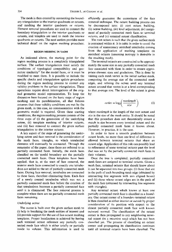
Figure 1 graphically depicts the basics of the YAOM. The first step of meshing a model face, or region, is to develop a variable level quadtree or octree which reflects the mesh control information and is consistent with the triangulation on the bound- ary of the entity, in that the quadrants or octants containing those entities have edge lengths on the order of the size of the finite element edges of the boundary triangulation of the entity being meshed. A one level difference on quadrants or octants sharing one or more edges is enforced during this process to control smoothness of the mesh gradations.
Once the quadtree or octree is generated the quad- rants and octants are classified as interior, exterior or containing part of the boundary triangulation. Those classified as exterior receive no further consideration. Those classified as interior are further classified into two groups. The first group maintains the classifi- cation of interior and contains those quadrants or octants with boundary entities far enough from the triangulation of the boundary of the model entity being meshed. The interior quadrants or octants having boundary entities which are considered too close to the boundary triangulation are given the classification of boundary like. The purpose of this differentiation is to avoid the problems caused when interior quadrant or octant entities are too close to the boundary to allow the creation of well shaped elements in the region between it and the triangu- lation of the boundary of the model entity. The definition of what constitutes an entity too close to the boundary triangulation can be reasonably defined by a range of distance values. Using the distance of about one-half the octant edge length as thc minimum works well.
n o r q u a d r a n t i BI - b o u n d a r y l ike in ter ior q u a d r a n t
. . . . . . . . . . . . . . . . . . . . . . . . : . . . . . . . . . . . . B - b o u n d a r y q u a d r a n t
Quadtree with Boundary Edges Unsmoothed Mesh
Fig. 1. Graphical depiction of the basics of YAOM.
314 HUGUES L. DE COUGNY et al.
The mesh is then created by connecting the bound- ary triangulation to the interior quadrants or octants, and meshing the interior quadrants or octants. Element removal procedures are used to connect the boundary triangulation to the interior quadrants or octants, and templets are used to mesh the interior quadrants or octants. The next section provides more technical detail on the region meshing procedure.
REGION MESHING IN YAOM
As indicated above, the starting point for the region meshing process is a completely triangulated surface. The surface triangulation must satisfy the conditions of topological compatibility and geo- metric similarity 12 for the model faces, or it must be modified to meet them. It is possible to include the specific checks and triangulation update procedures during the region meshing process to correct any validity problems in the surface triangulation. These operations require direct interrogations of the orig- inal geometric model representation. To keep the discussion here focused on the basic steps of region meshing and its parallelization, all that follows assumes that these validity conditions are met by the given mesh, in this case, no communication with the geometric model is required. Given these starting conditions, the region meshing process consists of the three steps of (i) the generation of the underlying octree, (ii) template meshing of interior octants, and (iii) face removal to connect the given surface triangulation to the interior octants.
A key aspect of the steps of generating the under- lying octree and face removal is the consideration of the mesh faces, triangles, to which tetrahedral elements will eventually be connected. Through the remainder of the paper, these faces are referred to as partially connected faces. Initially, the mesh faces classified on themodel boundary are the partially connected mesh faces. Once templates have been applied, that is, at the start of face removal, the interior mesh faces connected to exactly one tetrahe- dron are added to the set of partially connected mesh faces. During face removal, tetrahedra are connected to these faces, therefore eliminating them. Each face of a newly created tetrahedra which was not a partially connected mesh face before the creation of that tetrahedron becomes a partially connected face until it is eliminated. The face removal process is complete when there are no partially connected mesh faces remaining.
Underlying octree
The octree is built over the given surface mesh to (i) help in localizing the mesh entities of interest and (ii) provide support for the use of fast octant meshing templates. Proper localization is achieved by having each terminal octant reference any partially con- nected mesh face which is either totally or partially inside its volume. This information is used to
efficiently guarantee the correctness of the face removal technique. The octant building process can be decomposed into: (i) root octant building, (ii) octree building, (iii) level adjustment, (iv) assign- ment of partially connected mesh faces to terminal octants, and (v) terminal octant classification.
The root octant is such that the given surface mesh is contained within it. It is cubic in order to avoid the creation of unnecessary stretched tetrahedra coming from the application of meshing templates on stretched octants (assuming isotropy is desirable in the resulting mesh).
The terminal octants are constructed to be approxi- mately the same size as any partially connected mesh face associated with them in order to ensure appro- priate element sizes and gradations. This is done by visiting each mesh vertex in the initial surface mesh, computing the average size of the connected mesh edges, and refining the octree until any terminal octant around that vertex is at a level corresponding to that average size. The level of the octant is given by:
rootlength t octlev = log 2 7 s 1 z e
(1)
where rootlength is the length of the root octant and size is the size of the mesh entity. It should be noted that this procedure does not theoretically ensure a match in size between every terminal octant and the partially connected mesh faces it knows about. However, in practice, it is the case.
In order to have a smooth gradation between octant levels, no more than one level of difference is allowed between terminal octants that share an octant edge. Application of this rule can possibly lead to refinement of some terminal octants past the level that was set by the partially connected mesh faces in their volumes.
Once the tree is completed, partially connected mesh faces are assigned to terminal octants. Given a mesh face, terminal octants that should know about it can be separated into two groups: (i) those that are in the path of each bounding mesh edge (obtained by intersecting line segments with axis aligned boxes) and (ii) those whose octant edges are in the path of the mesh face (obtained by intersecting line segments with triangles).
Any terminal octant which knows at least one partially connected mesh face is classified as a bound- ary. One octant corner of a boundary terminal octant is then classified as either interior or outside by proper consideration of its position with respect to the closest partially connected mesh face with known outward normal. The classification of the octant corner is then propagated to any neighboring termi- nal octant (in a recursive way) which has not been classified yet. The process of classifying an octant corner and propagating its classification continues until all terminal octants have been classified. The
Parallel three-dimensional mesh generation 315
propagation of classification (through octant corner neighboring terminal octants) is possible because ter- minal octants classified as boundary clearly separate interior terminal octants from outside terminal octants.
After the basic octant classification process, interior octants can exist which have boundary enti- ties arbitrarily close to the surface triangles in the boundary octants. Since poorly shaped elements can result when these entities are too close, some interior terminal octants are reclassified as boundary-like. If a mesh vertex of an interior terminal octant is too close to a partially connected mesh face, poorly shaped elements are likely to be generated in this neighbor- hood. Therefore, if a mesh vertex on the boundary of a boundary terminal octant is too close to a partially
connected mesh face, all interior terminal octants neighboring that vertex are reclassified as boundao'- like. Since the interior octants are meshed with templates and the remainder of the mesh is created by face removals (connecting the partially connected mesh faces of the surface triangulation to the interior octants), the boundao'-like octants play no role in the remainder of the mesh generation process.
Template meshing o f interior octants
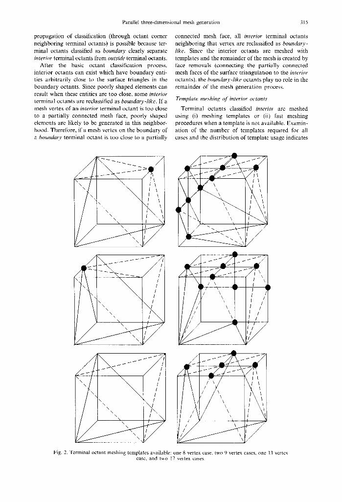
Terminal octants classified interior are meshed using (i) meshing templates or (ii) fast meshing procedures when a template is not available. Examin- ation of the number of templates required for all cases and the distribution of template usage indicates
I/ '\ T / 7 l / /,r \\ / , /
I/£i ",± ,'/
Fig. 2. Terminal octant meshing templates available: one 8 vertex case, two 9 vertex cases, one 13 vertex case, and two 17 vertex cases.
316 HUGUES L. DE COUGNY et al.
that octants with 8, 9, 13, and 17 vertices cover over 90% of the interior octants. All the 9, 13, and 17 vertex octant configurations can be meshed by 6 templates (Fig. 2) with the correct rotations applied.
The remaining interior octants are then quickly meshed using a fast procedure which accounts for the fact that the octant is a rectangular prism. One very fast option is to create an interior vertex and to create the correct connections to it. 1° Another approach is to use a fast element creation procedure which requires only limited checking due to the octant shape and fact that all vertices are at octant corner, mid-edge, or face centroid locations.
Face removal
Given a partially connected mesh face, a face removal consists of connecting it to a mesh vertex. Since the volume to be meshed consists of the space between the given surface triangulation and the interior octree, the vertex used is usually an existing one. However, in some situations, it is desirable to create a new vertex. The choice of the target vertex (existing or new) must be such that the created element is of good quality and its creation does not lead to poor (in terms of shape) subsequent face removals in that neighborhood.
Early element removal procedures had some difficulty in the process of determining the vertex to connect to, in that the criteria used emphasized the element being created with little consideration for the situation remaining for subsequent face removals. Consideration of the influence on subsequent face removals is a difficult process since one does not know about them until they arise. One possible solution is to make sure that any element creation does not create new mesh entities too close (relatively) to existing mesh entities. This process requires an exhaustive set of geometric checks against mesh entities in the neighborhood. Although it is possible to develop the appropriate set of checks, it is in general an expensive process since the number and complexity of checks required is quite high even when efficient procedures are used to provide a proper set of candidate mesh entities to consider. Moreover, the choice of the target vertex has to be made with respect to two different criteria which are difficult to relate to in an exact manner: (i) shape (for the element to be created) and (ii) relative distance. The existence of two different criteria and therefore thresholds is likely to lead in some cases to poor decisions. In order to be more consistent, one should consider a single measure for the purpose of comparing face removals to different target vertices. The creation of an element for the current face removal can potentially eliminate target vertices for nearby partially connected mesh faces. If, due to the presence of the to be created element, the best (in terms of shape) face removal for a nearby face is not possible (due to mesh entity intersection), the to be created element clearly inter- feres with the future removal of that nearby face. The
best possible shape for the removal of the nearby face can be recorded. The minimum of those shapes for all nearby faces (including the shape of the to be created element) is a measure of the quality of the face removal to a given target vertex. This approach is computationally expensive as well.
An alternative method is to use a more efficient criterion which indirectly accounts for the various situations that can arise. The Delaunay circumsphere criterion does provide a quality mesh when given a well distributed set of points. The use of the Delaunay criterion in general element removal mesh generation procedures has been shown to be an effective means to control this process. 13 ~5 One main advantage of using a Delaunay approach when advancing a front is the considerable reduction of intersection checks.
The current procedure combines the use of the octree, Delaunay meshing criterion, and more exhaustive checks when a local Delaunay solution is not available. Partially connected mesh faces are marked either Delaunay or non-Delaunay, t3 A par- tially connected mesh face classified as interior and whose connected element satisfies the Delaunay cri- terion (that is, is a Delaunay element) is Delaunay. Otherwise, it is non-Delaunay. This classification is important since a to-be-created Delaunay element has to be checked for intersection only with non- Delaunay partially connected mesh faces. Also, when a Delaunay element is created, the new bounding faces are automatically Delaunay. It is therefore clear that the more Delaunay elements are created, the fewer intersection checks will need to be performed.
The octree structure is used as a localization tool to provide a list of candidate mesh entities to consider (target vertices and nearby partially connected mesh faces). Since the boundary octants are defined to closely match the size of the surface triangles and the interior octants are meshed with elements matching the octant size, the process of getting a good set of octants from which to find candidate mesh entities is quite efficient. The tree neighborhood for a mesh face consists of all terminal octants neighboring (in con- tact) with the terminal octants knowing about the mesh face. The vertices of the partially connected faces in these octants provides the set of target vertices to consider.
The target vertex that satisfies the Delaunay cri- terion is searched for. This vertex is unique unless there is degeneracy (more than four points on the circumsphere). Degenerate cases must be handled with special attention as improper choices may lead to invalid triangulations. If none of the candidate vertices satisfy the Delaunay criterion for the given mesh face, a mesh vertex is inserted according to the procedure described in Ref. 14 with the additional constraint that it must guarantee the creation of a Delaunay element for the current face to remove. If a mesh vertex cannot be inserted, the previously described explicit procedure based solely on shape measure is used to select a target vertex. In that case,
Parallel three-dimensional mesh generation 317
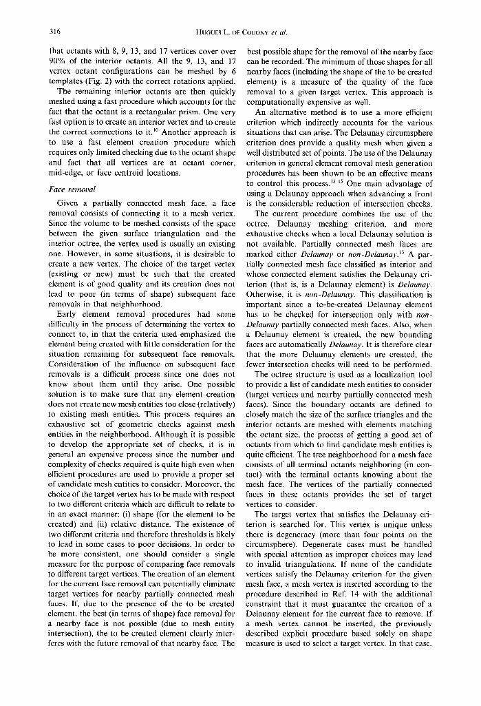
Fig. 3. Mesh example for sequential face removal.
intersection checks must be done with all nearby partially connected mesh faces whether they are Delaunay or non-Delaunay. Also, new faces resulting from the creation of the new element have to be marked non-Delaunay.
Face removals are performed on non-Delaunay partially connected mesh faces as long as there are some existing. The process of removing partially connected mesh faces ends when there is no more partially connected mesh faces. Figure 3 shows a surface triangulation meshed with face removals.
PARALLEL CONSTRUCTS REQUIRED
Octree and mesh data structures
The data structures used to control the distribution and communicat ion of information between pro- cessors are critical to the development of the parallel implementat ion of the region meshing procedures. The two data structures that support these processes are the octree and mesh data structures. The octree is used to control the distribution of information to processors while the mesh data structure is used to control the interprocessor communicat ion of mesh information. For purposes of region meshing, the octree is linked to the mesh data structure through the partially connected faces.
To efficiently gather the terminal octants in the path of a new face, any processor must be able to effectively determine which processor any given ter- minal octant is assigned. This information is easily available when each processor has full knowledge of the basic octree in terms of structure and processor assignment. Since this is a small amount of data relative to the overall data structures, this is the approach currently implemented. When mesh sizes reach well into the millions of elements, an alternative approach based on maintaining only portions of the
"t" In the context of a non-manifold representation, '6 these links represent links to use pairs where the interprocessor boundary is treated in the same manner as a material interface.
tree on individual processors will be required to provide the required scalablity.
In addition to the basic octree structure, each processor stores links between its assigned terminal octants and the finite element mesh. Each terminal octant stores a pointer to a list of on processor partially connected mesh faces and a pointer to a linked list of off-processor partially connected mesh faces. Since no interprocessor links are maintained in the octree data structure, octree neighboring infor- mation (like finding terminal octants neighboring an octant face, edge, or corner) is obtained through tree traversals when it is needed.
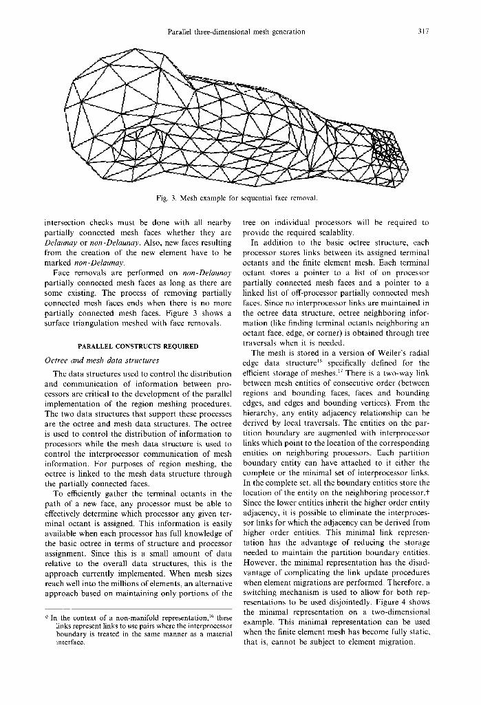
The mesh is stored in a version of Weiler's radial edge data structure ~6 specifically defined for the efficient storage of meshes. ~7 There is a two-way link between mesh entities of consecutive order (between regions and bounding faces, faces and bounding edges, and edges and bounding vertices). F rom the hierarchy, any entity adjacency relationship can be derived by local traversals. The entities on the par- tition boundary are augmented with interprocessor links which point to the location of the corresponding entities on neighboring processors. Each partit ion boundary entity can have attached to it either the complete or the minimal set of interprocessor links. In the complete set, all the boundary entities store the location of the entity on the neighboring processor.+ Since the lower entities inherit the higher order entity adjacency, it is possible to eliminate the interproces- sor links for which the adjacency can be derived from higher order entities. This minimal link represen- tation has the advantage of reducing the storage needed to maintain the parti t ion boundary entities. However, the minimal representation has the disad- vantage of complicating the link update procedures when element migrations are performed. Therefore, a switching mechanism is used to allow for both rep- resentations to be used disjointedly. Figure 4 shows the minimal representation on a two-dimensional example. This minimal representation can be used when the finite element mesh has become fully static, that is, cannot be subject to element migration.
318 HUGUES L. DE COUGNY et al.
Processor I Processor 2
. . . . . . . . . . . . . . i--t- .... t .... ...... +- i - ...................
Processor 4
V P r o c e s s o r 3
Fig. 4. Interprocessor links (minimal links).
Multiple octant migration
As indicated previously, the face removal process requires knowledge of the partially connected faces in its neighborhood to determine the proper connection to remove it. Any neighborhood information for a face being removed which is not fully on-processor must be sent to that processor. This information is provided by migrating octants and their associated information. The migration of octants is also used to re-balance the work load on the processors during the region meshing procedure.
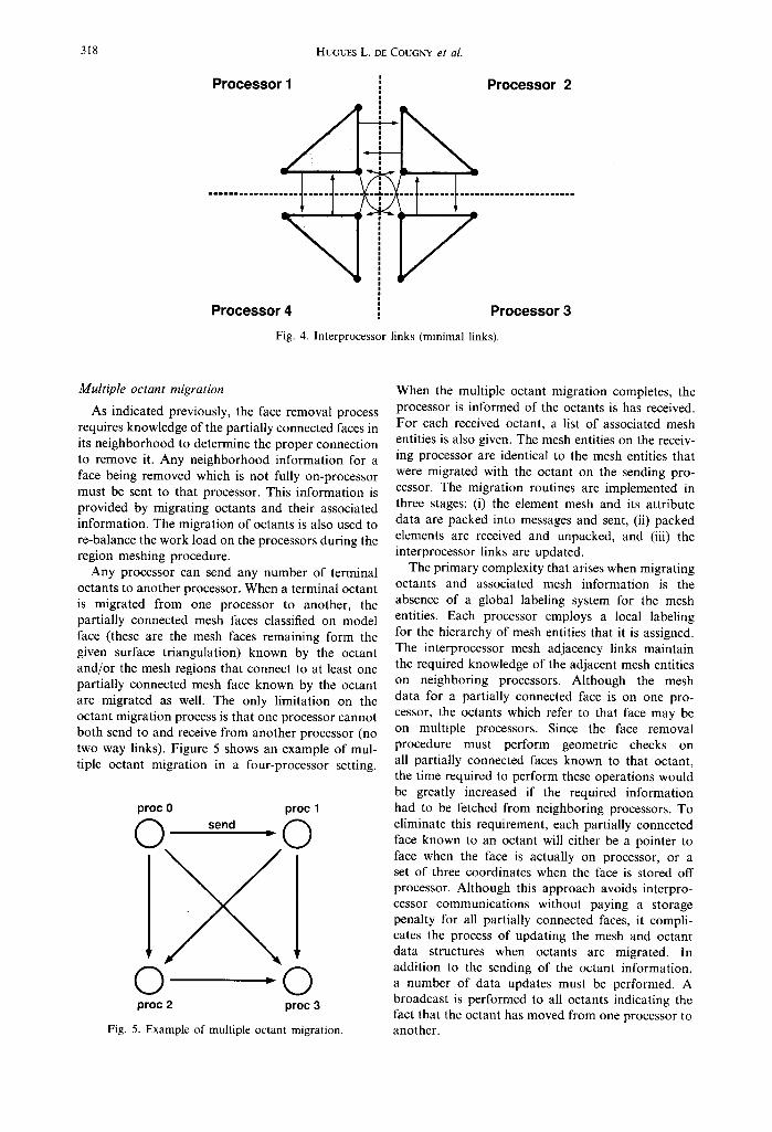
Any processor can send any number of terminal octants to another processor. When a terminal octant is migrated from one processor to another, the partially connected mesh faces classified on model face (these are the mesh faces remaining form the given surface triangulation) known by the octant and/or the mesh regions that connect to at least one partially connected mesh face known by the octant are migrated as well. The only limitation on the octant migration process is that one processor cannot both send to and receive from another processor (no two way links). Figure 5 shows an example of mul- tiple octant migration in a four-processor setting.
Fig.
proc 0 proc 1
sen° " 0
0 "0 proc 2 proc 3
5. Example of multiple octant migration.
When the multiple octant migration completes, the processor is informed of the octants is has received. For each received octant, a list of associated mesh entities is also given. The mesh entities on the receiv- ing processor are identical to the mesh entities that were migrated with the octant on the sending pro- cessor. The migration routines are implemented in three stages: (i) the element mesh and its attribute data are packed into messages and sent, (ii) packed elements are received and unpacked, and (iii) the interprocessor links are updated.
The primary complexity that arises when migrating octants and associated mesh information is the absence of a global labeling system for the mesh entities. Each processor employs a local labeling for the hierarchy of mesh entities that it is assigned. The interprocessor mesh adjacency links maintain the required knowledge of the adjacent mesh entities on neighboring processors. Although the mesh data for a partially connected face is on one pro- cessor, the octants which refer to that face may be on multiple processors. Since the face removal procedure must perform geometric checks on all partially connected faces known to that octant, the time required to perform these operations would be greatly increased if the required information had to be fetched from neighboring processors. To eliminate this requirement, each partially connected face known to an octant will either be a pointer to face when the face is actually on processor, or a set of three coordinates when the face is stored off processor. Although this approach avoids interpro- cessor communications without paying a storage penalty for all partially connected faces, it compli- cates the process of updating the mesh and octant data structures when octants are migrated. In addition to the sending of the octant information, a number of data updates must be performed. A broadcast is performed to all octants indicating the fact that the octant has moved from one processor to another.
Parallel three-dimensional mesh generation 319
Load balancing
During the earlier steps of the meshing process, it is difficult to accurately predict the distribution of computat ional load so that the initial parti t ioning of the octants to processors will yield equal work load per processor. In addition, the octant migration required during the face removal process to provide required information can introduce further work load imbalance. Therefore, it is desirable to re-balance the work load at the appropriate times during the mesh- ing process. Since the first step of constructing the underlying octree is not yet parallelized, no consider- ation has been given to re-balancing work load during that step. Since the amount of effort required to mesh interior octants using templates is about the same for each octant, work load balance is easily obtained by distributing work based on the number of interior octants per processor. The last set of face removal is the most computat ionally intensive and one where the per processor work load is difficult to predict and is altered during the process. As indicated previously, the face removal is performed by process- ing waves of unconnected faces. In the current implementation, load balancing is performed after each wave. The criterion used is to balance the number of partially connected faces on each processor.
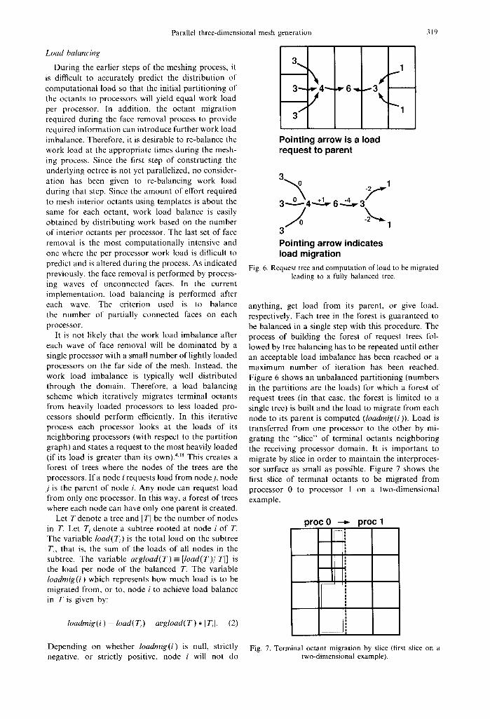
It is not likely that the work load imbalance after each wave of face removal will be dominated by a single processor with a small number of lightly loaded processors on the far side of the mesh. Instead, the work load imbalance is typically well distributed through the domain. Therefore, a load balancing scheme which iteratively migrates terminal octants from heavily loaded processors to less loaded pro- cessors should perform efficiently. In this iterative process each processor looks at the loads of its neighboring processors (with respect to the partit ion graph) and states a request to the most heavily loaded (if its load is greater than its own). 418 This creates a forest of trees where the nodes of the trees are the processors. If a node i requests load from node j, node j is the parent of node i. Any node can request load from only one processor. In this way, a forest of trees where each node can have only one parent is created.
Let T denote a tree and b TI be the number of nodes in T. Let Ti denote a subtree rooted at node i of 7". The variable load(T,) is the total load on the subtree T,, that is, the sum of the loads of all nodes in the subtree. The variable a v g l o a d ( T ) - [load(T)/lTI] is the load per node of the balanced T. The variable loadmig(i) which represents how much load is to be migrated from, or to, node i to achieve load balance in T is given by:
loadmig(i ) = load(Ti) - avgload(T) * ITil. (2)
3 ~ 1 • . \ , t
3"-- ~" 4"-- ~'6-4 ---3 • , j \
3 j ~1
Pointing arrow is a load request to parent
3
30~4.......~6-4~,.~3 ~ ' 1
3
Pointing arrow indicates load migration
Fig. 6. Request tree and computation of load to be migrated leading to a fully balanced tree.
anything, get load from its parent, or give load, respectively. Each tree in the forest is guaranteed to be balanced in a single step with this procedure. The process of building the forest of request trees fol- lowed by tree balancing has to be repeated until either an acceptable load imbalance has been reached or a maximum number of iteration has been reached. Figure 6 shows an unbalanced parti t ioning (numbers in the partitions are the loads) for which a forest of request trees (in that case, the forest is limited to a single tree) is built and the load to migrate from each node to its parent is computed (loadmig(i)). Load is transferred from one processor to the other by mi- grating the "'slice" of terminal octants neighboring the receiving processor domain. It is important to migrate by slice in order to maintain the interproces- sor surface as small as possible. Figure 7 shows the first slice of terminal octants to be migrated from processor 0 to processor 1 on a two-dimensional example.
procO --~ proc 1 i i
i | |
i
I i
i I | I m
I I u
I | |
Depending on whether loadrnig(i) is null, strictly Fig. 7. Terminal octant migration by slice (first slice on a negative, or strictly positive, node i will not do two-dimensional example).
320 HUGUES L. DE COUGNY et al.
1 D 8 - - I
6 5 0 0 1
:oo,, 5 0 0 0
4 5 0 0
4000
3 5 0 0
3000
i i i
M a x . l o a d -~ - - A v g . l o a d - + -
\ . . . . + . . . . - I - - - - - . + - - - - - - 4 - . . . . + . . . . - t - - - - - 4 - - - - ~ . . . .
I I I I I I I I
1 2 3 4 5 6 7 8
Nbr of iterations
9 5 0 0 , , , , , , Max. load - e - -
9 0 0 0 1 A v g . l o a d - + -
8 5 0 0 1
s o o o l
75001
70001
6 5 0 0 1
6 0 0 0 1
55001
O - - - . ¢ 0 ~ A 5 0 0 0 ~ - - - -+ . . . . + - - - - ÷ - - - - 4 - . . . . + . . . . - ~ - - - - ~ - - - --~" . . . . .
4 5 0 0 1 J i I L I i I I 0 1 2 3 4 5 6 7 8 9
Nbr of iterations
Fig. 8. Load balancing examples.
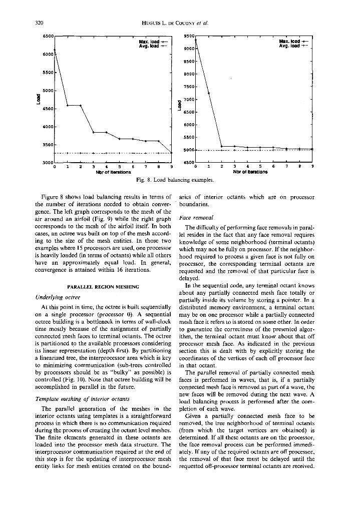
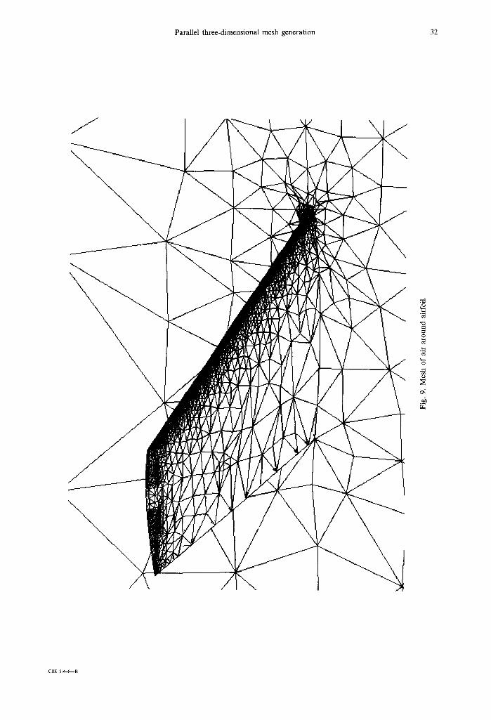
Figure 8 shows load balancing results in terms of the number of iterations needed to obtain conver- gence. The left graph corresponds to the mesh of the air around an airfoil (Fig. 9) while the right graph corresponds to the mesh of the airfoil itself. In both cases, an octree was built on top of the mesh accord- ing to the size of the mesh entities. In those two examples where 15 processors are used, one processor is heavily loaded (in terms of octants) while all others have an approximately equal load. In general, convergence is attained within 16 iterations.
PARALLEL REGION MESHING
Underlying octree
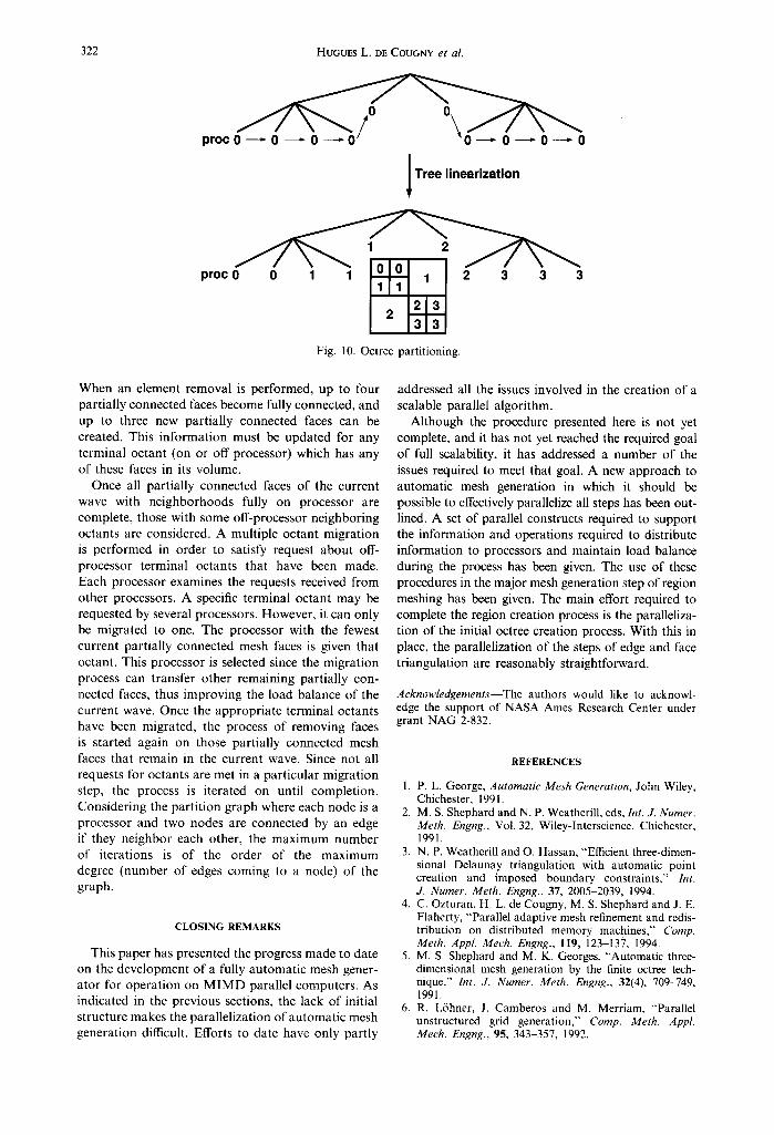
At this point in time, the octree is built sequentially on a single processor (processor 0). A sequential octree building is a bottleneck in terms of wall-clock time mostly because of the assignment of partially connected mesh faces to terminal octants. The octree is partitioned to the available processors considering its linear representation (depth first). By partitioning a linearized tree, the interprocessor area which is key to minimizing communication (sub-trees controlled by processors should be as "bulky" as possible) is controlled (Fig. 10). Note that octree building will be accomplished in parallel in the future.
Template meshing of interior octants
The parallel generation of the meshes in the interior octants using templates is a straightforward process in which there is no communication required during the process of creating the octant level meshes. The finite elements generated in these octants are loaded into the processor mesh data structure. The interprocessor communication required at the end of this step is for the updating of interprocessor mesh entity links for mesh entities created on the bound-
aries of interior octants which are on processor boundaries.
Face removal
The difficulty of performing face removals in paral- lel resides in the fact that any face removal requires knowledge of some neighborhood (terminal octants) which may not be fully on processor. If the neighbor- hood required to process a given face is not fully on processor, the corresponding terminal octants are requested and the removal of that particular face is delayed.
In the sequential code, any terminal octant knows about any partially connected mesh face totally or partially inside its volume by storing a pointer. In a distributed memory environment, a terminal octant may be on one processor while a partially connected mesh face it refers to is stored on some other. In order to guarantee the correctness of the presented algor- ithm, the terminal octant must know about that off processor mesh face. As indicated in the previous section this is dealt with by explicitly storing the coordinates of the vertices of each off processor face in that octant.
The parallel removal of partially connected mesh faces is performed in waves, that is, if a partially connected mesh face is removed as part of a wave, the new faces will be removed during the next wave. A load balancing process is performed after the com- pletion of each wave.
Given a partially connected mesh face to be removed, the tree neighborhood of terminal octants (from which the target vertices are obtained) is determined. If all these octants are on the processor, the face removal process can be performed immedi- ately. If any of the required octants are off processor, the removal of that face must be delayed until the requested off-processor terminal octants are received.
Parallel three-dimensional mesh generation 32
J
\ . d
.o
CSE 5 / 4 ~ - B
322 HUGUES L. DE COUGNY el al.
procO , 0 -~-- 0 - - . - 0 0 - ~ - 0 m. - 0 - - . - 0
I T r ~ linearization
o,o, procO 0 1 1 I 2 3 3 3 1 1 1 1 =
2 [ 3 2 3[3
Fig. 10. Octree partitioning.
When an element removal is performed, up to four partially connected faces become fully connected, and up to three new partially connected faces can be created. This information must be updated for any terminal octant (on or off processor) which has any of these faces in its volume.
Once all partially connected faces of the current wave with neighborhoods fully on processor are complete, those with some off-processor neighboring octants are considered. A multiple octant migration is performed in order to satisfy request about off- processor terminal octants that have been made. Each processor examines the requests received from other processors. A specific terminal octant may be requested by several processors. However, it can only be migrated to one. The processor with the fewest current partially connected mesh faces is given that octant. This processor is selected since the migration process can transfer other remaining partially con- nected faces, thus improving the load balance of the current wave. Once the appropriate terminal octants have been migrated, the process of removing faces is started again on those partially connected mesh faces that remain in the current wave. Since not all requests for octants are met in a particular migration step, the process is iterated on until completion. Considering the partit ion graph where each node is a processor and two nodes are connected by an edge if they neighbor each other, the maximum number of iterations is of the order of the maximum degree (number of edges coming to a node) of the graph.
CLOSING REMARKS
This paper has presented the progress made to date on the development of a fully automatic mesh gener- ator for operat ion on M I M D parallel computers. As indicated in the previous sections, the lack of initial structure makes the parallelization of automatic mesh generation difficult. Efforts to date have only partly
addressed all the issues involved in the creation of a scalable parallel algorithm.
Although the procedure presented here is not yet complete, and it has not yet reached the required goal of full scalability, it has addressed a number of the issues required to meet that goal. A new approach to automatic mesh generation in which it should be possible to effectively parallelize all steps has been out- lined. A set of parallel constructs required to support the information and operations required to distribute information to processors and maintain load balance during the process has been given. The use of these procedures in the major mesh generation step of region meshing has been given. The main effort required to complete the region creation process is the paralleliza- tion of the initial octree creation process. With this in place, the parallelization of the steps of edge and face triangulation are reasonably straightforward.
Acknowledgements--The authors would like to acknowl- edge the support of NASA Ames Research Center under grant NAG 2-832.
REFERENCES
1. P. L. George, Automatic Mesh Generation, John Wiley, Chichester, 1991.
2. M. S. Shephard and N. P. Weatherill, eds, bu. J. Numer. Meth. Engng., Vol. 32, Wiley-lnterscience, Chichester, 1991.
3. N. P. Weatherill and O. Hassan, "Efficient three-dimen- sional Delaunay triangulation with automatic point creation and imposed boundary constraints," Int. J. Numer. Meth. Engng., 3"/, 2005 2039, 1994.
4. C. Ozturan, H. L. de Cougny, M. S. Shephard and J. E. Flaherty, "'Parallel adaptive mesh refinement and redis- tribution on distributed memory machines," Comp. Meth. Appl. Mech. Engng., 119, 123-137, 1994.
5. M. S. Shephard and M. K. Georges, "'Automatic three- dimensional mesh generation by the finite octree tech- nique," Int. J. Numer. Meth. Engng., 32(4), 709-749, 1991.
6. R. L6hner, J. Camberos and M. Merriam, "'Parallel unstructured grid generation," Comp. Meth. Appl. Mech. Engng., 95, 343 357, 1992.

Parallel three-dimensional mesh generation 323
7. M. Saxena and R. Perucchio, "Parallel FEM algorithms based on recursive spatial decompositions--I. Auto- matic mesh generation," Comput. Struct., 45, 817-831, 1992.
8. W. J. Schroeder and M. S. Shephard, "A combined octree/Delaunay method for fully automatic 3-D mesh generation," Int. J. Numer. Meth. Engng., 29, 37 55, 1990.
9. M. S. Shephard and M. K. Georges, "Reliability of automatic 3-D mesh generation," Comp. Meth. Appl. Mech. Engng., 101,443-462, 1992.
10. M. A. Yerry and M. S. Shephard, "Automatic three- dimensional mesh generation by the modified-octree technique," Int. J. Numer. Meth. Engng., 20, 1965 1990, 1984.
11. H. L. de Cougny, K. D. Devine, J. E. Flaherty, R. M. Loy, C. Ozturan and M. S. Shephard, "Load balancing for the parallel solution of partial differential equations," Applied Numerical Mathematics, submitted.
12. W. J. Schroeder and M. S. Shephard, "On rigorous conditions for automatically generated finite element meshes," in J. Turner, J. Pegna and M. Wozny, eds, Product Modeling for Computer-Aided Design and Man- ufacturing, pp. 267 281. North Holland, 1991.
13. S. H. Lo, "Delaunay triangulation of non-convex planar domains," Int. J. Numer. Meth. Engng., 28, 2695 2707, 1989.
14. D. J. Mavriplis, "An advancing front Delaunay triangu- lation algorithm designed for robustness," Number AIAA-93-0671, 31st Aerospace Sciences Meeting and Exhibit, AIAA, Washington, D.C., Jan. 1993.
15. M. L. Merriam, "An efficient advancing front algorithm for Delaunay triangulation," Number AIAA-91-792. AIAA, Washington, D.C., 1991.
16. K. J. Weiler, "'The radial-edge structure: a topological representation for non-manifold geometric boundary representations," in M. J. Wozny, H. W. McLaughlin and J. L. Encarnacao, eds, Geometric Modeling for CAD Applications, pp. 3 36. North Holland, 1988.
17. M. W. Beall, "Scorec mesh database users guide, ver- sion 2 . 2 ~ r a f t , " Technical Report SCOREC #26- 1993, Scientific Computation Research Center, Rensselaer Polytechnic Institute, Troy, NY 12180-3590, 1993.
18. E. Leiss and H. Reddy, "Distributed load balancing: design and performance analysis," Technical Report, Vol. 5, W. M. Keck Research Computation Laboratory, 1989.