parallel port shark projectshark.sssup.it/distrib/demos_doc/parport/parport... · 2003-05-28 ·...
TRANSCRIPT

Università degli Studi di PaviaFacoltà di Ingegneria
Dipartimento di Informatica e Sistemistica
PARALLEL PORTSHARK PROJECT
COMUNICAZIONE TRA PERSONAL COMPUTERTRAMITE PORTA PARALLELA
Corso: Informatica Industriale – A.A. 2001/2002Docente: Prof. Giorgio ButtazzoResponsabili: Prof. Giorgio Buttazzo – Ing. Paolo Gai
Progetto: Parallel Port Shark ProjectAutori: Andrea Battistotti, Armando Leggio
APPENDICEDocumentazione raccolta da Internet

APPENDICEDOCUMENTAZIONE RACCOLTA DA INTERNET
Interfacing to theIBM-PC Parallel Printer Port
The original IBM-PC's Parallel Printer Port had a total of 12 digital outputs and 5 digital inputs accessed via 3 consecutive 8-bit ports in theprocessor's I/O space.
• 8 output pins accessed via the DATA Port• 5 input pins (one inverted) accessed via the STATUS Port• 4 output pins (three inverted) accessed via the CONTROL Port• The remaining 8 pins are grounded
25-way Female D-Type Connector
Various enhanced versions of the original specification have been introduced over the years• Bi-directional (PS/2)• Enhanced Parallel Port (EPP)• Extended Capability Port (ECP)
so now the original is commonly referred to as the Standard Parallel Port (SPP)
IBM-PC Parallel Printer PortIntroduction
IBM originally supplied three adapters that included a parallel printer port for its PC/XT/AT range of microcomputers. Depending on whichwere installed, each available parallel port's base address in the processor's I/O space would be one of 278, 378 and 3BC (all Hex).
Most (All?) contemporary PCs, shipped with a single parallel printer port, seem to have the base address at 378 Hex.
The PC parallel port adapter is specifically designed to attach printers with a parallel port interface, but it can be used as a generalinput/output port for any device or application that matches its input/output capabilities. It has 12 TTL-buffer output points, which arelatched and can be written and read under program control using the processor In or Out instruction. The adapter also has five steady-stateinput points that may be read using the processor's In instruction.
In addition, one input can also be used to create a processor interrupt. This interrupt can be enabled and disabled under program control.Reset from the power-on circuit is also ORed with a program output point, allowing a device to receive a power-on reset when the processorin reset.
The input/output signals are made available at the back of the adapter through a right-angled, PCB-mounted, 25-pin, D-type femaleconnector. This connector protudes through the rear panel of the system, where a cable may be attached.
When this adapter is used to attach a printer, data or printer commands are loaded into an 8-bit, latched, output port, and the strobe line isactivated, writing data to the printer. The program then may read the input ports for printer status indicating when the next character can bewritten, or it may use the interrupt line to indicate "not busy" to the software.
The printer adapter responds to five I/O instructions: two output and three input. The output instructions transfer data into two latches whoseoutputs are presented on the pins of a 25-pin D-type female connector.
Two of the three input instructions allow the processor to read back the contents of the two latches. The third allows the processor to read therealtime status of a group of pins on the connector.
A description of each instruction follows
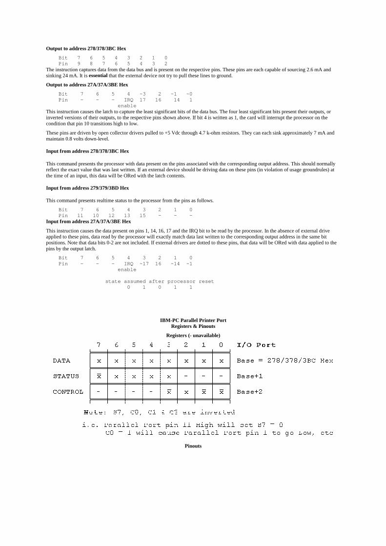
Output to address 278/378/3BC Hex
Bit 7 6 5 4 3 2 1 0 Pin 9 8 7 6 5 4 3 2The instruction captures data from the data bus and is present on the respective pins. These pins are each capable of sourcing 2.6 mA andsinking 24 mA. It is essential that the external device not try to pull these lines to ground.
Output to address 27A/37A/3BE Hex
Bit 7 6 5 4 ~3 2 ~1 ~0 Pin - - - IRQ 17 16 14 1 enableThis instruction causes the latch to capture the least significant bits of the data bus. The four least significant bits present their outputs, orinverted versions of their outputs, to the respective pins shown above. If bit 4 is written as 1, the card will interrupt the processor on thecondition that pin 10 transitions high to low.
These pins are driven by open collector drivers pulled to +5 Vdc through 4.7 k-ohm resistors. They can each sink approximately 7 mA andmaintain 0.8 volts down-level.
Input from address 278/378/3BC Hex
This command presents the processor with data present on the pins associated with the corresponding output address. This should normallyreflect the exact value that was last written. If an external device should be driving data on these pins (in violation of usage groundrules) atthe time of an input, this data will be ORed with the latch contents.
Input from address 279/379/3BD Hex
This command presents realtime status to the processor from the pins as follows.
Bit 7 6 5 4 3 2 1 0 Pin 11 10 12 13 15 - - -Input from address 27A/37A/3BE Hex
This instruction causes the data present on pins 1, 14, 16, 17 and the IRQ bit to be read by the processor. In the absence of external driveapplied to these pins, data read by the processor will exactly match data last written to the corresponding output address in the same bitpositions. Note that data bits 0-2 are not included. If external drivers are dotted to these pins, that data will be ORed with data applied to thepins by the output latch.
Bit 7 6 5 4 3 2 1 0 Pin - - - IRQ ~17 16 ~14 ~1 enable
state assumed after processor reset 0 1 0 1 1
IBM-PC Parallel Printer PortRegisters & Pinouts
Registers (- unavailable)
Pinouts
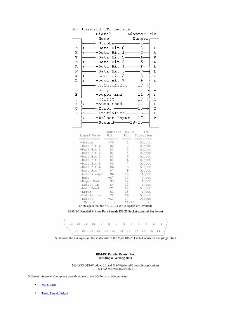
Register DB-25 I/OSignal Name Bit Pin Direction=========== ======== ===== =========-Strobe ¬C0 1 Output+Data Bit 0 D0 2 Output+Data Bit 1 D1 3 Output+Data Bit 2 D2 4 Output+Data Bit 3 D3 5 Output+Data Bit 4 D4 6 Output+Data Bit 5 D5 7 Output+Data Bit 6 D6 8 Output+Data Bit 7 D7 9 Output-Acknowledge S6 10 Input+Busy ¬S7 11 Input+Paper End S5 12 Input+Select In S4 13 Input-Auto Feed ¬C1 14 Output-Error S3 15 Input-Initialize C2 16 Output-Select ¬C3 17 Output Ground - 18-25 -
(Note again that the S7, C0, C1 & C3 signals are inverted)
IBM-PC Parallel Printer Port Female DB-25 Socket external Pin layout
______________________________________________________/ \\ 13 12 11 10 9 8 7 6 5 4 3 2 1 / \ / \ 25 24 23 22 21 20 19 18 17 16 15 14 / \________________________________________________/
So it's also the Pin layout on the solder side of the Male DB-25 Cable Connector that plugs into it
IBM-PC Parallel Printer PortReading & Writing Data
MS-DOS, MS-Windows3.1 and MS-Windows95 console applicationsbut not MS-Windows95/NT
Different interpreters/compilers provide access to the I/O Ports in different ways.
• MS-QBasic
• Turbo Pascal, Delphi

• Turbo C, Borland C/C++
• Microsoft Visual C/C++
• Watcom C/C++
or you can use Debug
For full details, refer to the relevant manuals.
• Randy Rasa has written a PC Printer Port I/O Module for Borland C/C++ v3.1 which provides the low-level control of the port,implementing code to control 12 outputs and read 5 inputs.
• Kyle A. York wote an article on High-Speed Transfers on a PC Parallel Port for the C/C++ Users Journal. The accompanyingsource files (york.zip) are included in the November 1996 ZIPped file in their Code Archive.
Note:I have no personal experience of I/O port access in Windows 95/NT or linux (so please don't ask). MS-DOS is sufficient for (prototyping)the kinds of control systems I am interested in.
However, I recommend our students use the DriverLINX Port I/O Driver for Win95 and WinNT, provided without charge by ScientificSoftware Tools, Inc. Here's the README file and a local copy (1.5MB) of the package.
Some links that might be useful
• Jan Axelson's Parallel Port Central includes information on programming I/O Port access under MS-Windows
• Vincent Himpe's free WINio / WIN95io DLL restores the INP and OUT functions missing from Visual Basic.
• Dale Edgar's PortIO95 is a Windows 95 VxD that provides a simple Application Programming Interface to the PC Parallel Port(free for non-commercial use).
• Fred Bulback's free IO16.DLL / IO.DLL provide I/O Port access for Windows 3.x / 95
• SoftCircuits' free Programming Tools and Libraries include vbasm.zip, a 16-bit DLL that provides a range of functionalityincluding Port I/O, and win95io.zip, a tiny DLL that allows Port I/O under Windows 95.
• Dan Hoehnen's Port16 / Port32 are shareware OCXs that add I/O port access capability to Visual Basic.
• Rob Woudsma's IOPORT/NTPORT are shareware OCXs for Visual Basic under Windows 95/NT
• Herve Couplet has sent me an example of I/O Port Access in Borland C++ Builder 1.0
• Samuel Grimee's Programming the parallel port under Windows NT
• Cooperative Knowledge, Inc. has some Technical Papers that include tutorials on writing DLLs by Glenn D. Jones
• Frequently Asked Questions (FAQ) from the comp.os.ms-windows.programmer.vxd newsgroup
and for linux enthusiasts -
• local copy (text) of Riku Saikkonen's Linux I/O port programming mini-HOWTO (HTML)
• Linux Parallel Port Home Page
[ Previous ] [ Index ] [ Next ]
last updated: 30-Nov-98 Ian Harries <[email protected]>
I/O Port Access in QBasic
QBasic provides access to the I/O ports on the 80x86 CPU via the INP function and the OUT statement.
INP(portid) ' returns a byte read from the I/O port portid
OUT portid, value ' writes the byte value to the I/O port portidportid can be any unsigned integer in the range 0-65535. value is in the range 0-255.pdata = &H378
status = &H379control = &H37A
OUT pdata, bits ' output data
bits = INP(status) ' input data
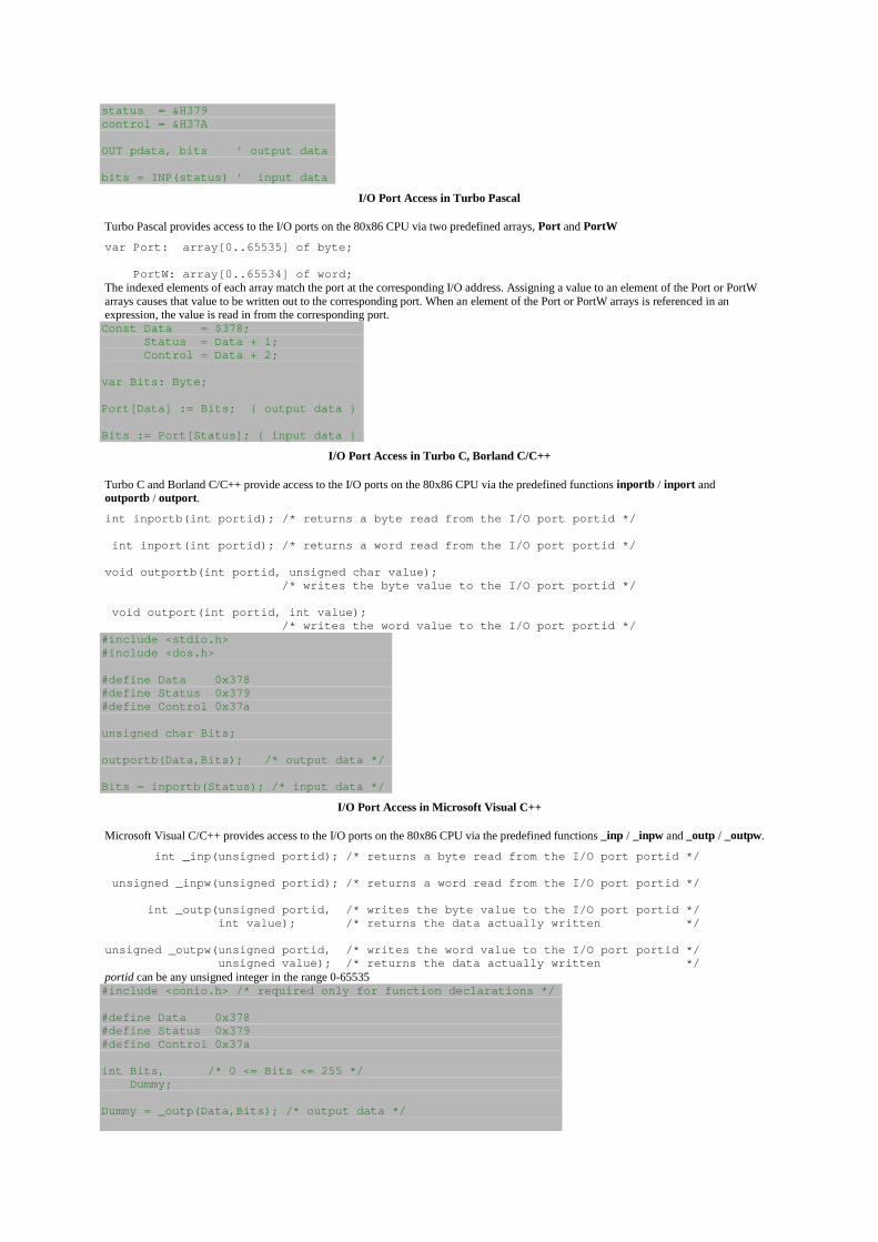
I/O Port Access in Turbo Pascal
Turbo Pascal provides access to the I/O ports on the 80x86 CPU via two predefined arrays, Port and PortW
var Port: array[0..65535] of byte;
PortW: array[0..65534] of word;The indexed elements of each array match the port at the corresponding I/O address. Assigning a value to an element of the Port or PortWarrays causes that value to be written out to the corresponding port. When an element of the Port or PortW arrays is referenced in anexpression, the value is read in from the corresponding port.Const Data = $378; Status = Data + 1; Control = Data + 2;
var Bits: Byte;
Port[Data] := Bits; { output data }
Bits := Port[Status]; { input data }
I/O Port Access in Turbo C, Borland C/C++
Turbo C and Borland C/C++ provide access to the I/O ports on the 80x86 CPU via the predefined functions inportb / inport andoutportb / outport.
int inportb(int portid); /* returns a byte read from the I/O port portid */
int inport(int portid); /* returns a word read from the I/O port portid */
void outportb(int portid, unsigned char value); /* writes the byte value to the I/O port portid */
void outport(int portid, int value); /* writes the word value to the I/O port portid */#include <stdio.h>#include <dos.h>
#define Data 0x378#define Status 0x379#define Control 0x37a
unsigned char Bits;
outportb(Data,Bits); /* output data */
Bits = inportb(Status); /* input data */
I/O Port Access in Microsoft Visual C++
Microsoft Visual C/C++ provides access to the I/O ports on the 80x86 CPU via the predefined functions _inp / _inpw and _outp / _outpw.
int _inp(unsigned portid); /* returns a byte read from the I/O port portid */
unsigned _inpw(unsigned portid); /* returns a word read from the I/O port portid */
int _outp(unsigned portid, /* writes the byte value to the I/O port portid */ int value); /* returns the data actually written */
unsigned _outpw(unsigned portid, /* writes the word value to the I/O port portid */ unsigned value); /* returns the data actually written */portid can be any unsigned integer in the range 0-65535#include <conio.h> /* required only for function declarations */
#define Data 0x378#define Status 0x379#define Control 0x37a
int Bits, /* 0 <= Bits <= 255 */ Dummy;
Dummy = _outp(Data,Bits); /* output data */
Bits = _inp(Status); /* input data */
I/O Port Access in Watcom C
Watcom C provides access to the I/O ports on the 80x86 CPU via the predefined functions inp / inpw and outp / outpw.
unsigned int inp(int portid); /* returns a byte read from the I/O port portid */
unsigned int inpw(int portid); /* returns a word read from the I/O port portid */
unsigned int outp(int portid, /* writes the byte value to the I/O port portid */ int value); /* returns the data actually written */
unsigned int outpw(int portid, /* writes the word value to the I/O port portid */ unsigned int value); /* returns the data actually written */portid can be any unsigned integer in the range 0-65535#include <conio.h>
#define Data 0x378#define Status 0x379#define Control 0x37a
int Bits, /* 0 <= Bits <= 255 */ Dummy;
Dummy = outp(Data,Bits); /* output data */
Bits = inp(Status); /* input data */
PC Printer Port I/O Module
While not strictly an embedded application, the standard PC printer port is handy for testing and controlling devices. It provides an easy wayto implement a small amout of digital I/O. I like to use to during initial development of a product -- before the "real" hardware is ready, I candummy up a circuit using the printer port, and thus get started testing my software.
PC to PC file transfer
Supervisor: Ian Harries <[email protected]>
ObjectiveTo provide a facility for file transfer between two PCs connected via their parallel printer ports.
DescriptionAlthough the IBM-PC parallel printer port is intended for output only, there are enough input lines available for 4-bit I/O, with handshaking,so data bytes can be transferred half at a time.
Introduction to the IEEE 1284-1994 Standard
This section is implemented as a multilevel document. This page serves as an executive summary of the 1284 standard. Byclicking on the various highlighted points, you may explore each concept in greater detail.
The recently released standard, "IEEE Std.1284-1994 Standard Signaling Method for a Bi-directional Parallel PeripheralInterface for Personal Computers", is for the parallel port what the Pentium processor is to the 286. The standard provides forhigh speed bi-directional communication between the PC and an external peripheral that can communicate 50 to 100 timesfaster than the original parallel port. It can do this and still be fully backward compatible with all existing parallel port peripheralsand printers.
Click here for a history and background of the parallel port.
The 1284 standard defines 5 modes of data transfer. Each mode provides a method of transferring data in either the forwarddirection (PC to peripheral), reverse direction (peripheral to PC) or bi-directional data transfer (half duplex). The defined modesare:
• Forward direction onlyCompatibility Mode"Centronics" or standard mode
• Reverse direction onlyNibble Mode

4 bits at a time using status lines for data.Hewlett Packard Bi-tronicsByte Mode8 bits at a time using data lines, sometimes referred to as a "bi-directional" port.
• Bi-directionalEPPEnhanced Parallel Port- used primarily by non-printer peripherals, CD ROM, tape, hard drive, network adapters, etc....ECPExtended Capability Port- used primarily by new generation of printers and scanners
All parallel ports can implement a bi-directional link by using the Compatible and Nibble modes for data transfer. Byte mode canbe utilized by about 25% of the installed base of parallel ports. All three of these modes utilize software only to transfer the data.The driver has to write the data, check the handshake lines (i.e.: BUSY), assert the appropriate control signals (i.e.: STROBE)and then go on to the next byte. This is very software intensive and limits the effective data transfer rate to 50 to 100 Kbytes persecond.
In addition to the previous 3 modes, EPP and ECP are being implemented on the latest I/O controllers by most of the Super I/Ochip manufacturers. These modes use hardware to assist in the data transfer. For example, in EPP mode, a byte of data can betransferred to the peripheral by a simple OUT instruction. The I/O controller handles all the handshaking and data transfer to theperipheral.
Overall, the 1284 standard provides the following:
1. 5 modes of operation for data transfer
2. A method for the host and peripheral to determine the supported modes and to negotiate to the requested mode.
3. Defines the physical interface
o Cables
o Connectors
4. Defines the electrical interface
o Drivers/Receivers
o Termination
o Impedance
In summary, the 1284 parallel port provides an easy to use, high performance interface for portable products and printers.
The Linux 2.4 Parallel Port Subsystem<<< Previous Next >>>
Design goals
The problems
The first parallel port support for Linux came with the line printer driver, lp. The printer driver is a character special device, and (in Linux2.0) had support for writing, via write, and configuration and statistics reporting via ioctl.
The printer driver could be used on any computer that had an IBM PC-compatible parallel port. Because some architectures have parallelports that aren't really the same as PC-style ports, other variants of the printer driver were written in order to support Amiga and Atariparallel ports.
When the Iomega Zip drive was released, and a driver written for it, a problem became apparent. The Zip drive is a parallel port device thatprovides a parallel port of its own---it is designed to sit between a computer and an attached printer, with the printer plugged into the Zipdrive, and the Zip drive plugged into the computer.
The problem was that, although printers and Zip drives were both supported, for any given port only one could be used at a time. Only one ofthe two drivers could be present in the kernel at once. This was because of the fact that both drivers wanted to drive the same hardware---theparallel port. When the printer driver initialised, it would call the check_region function to make sure that the IO region associated withthe parallel port was free, and then it would call request_region to allocate it. The Zip drive used the same mechanism. Whicheverdriver initialised first would gain exclusive control of the parallel port.
The only way around this problem at the time was to make sure that both drivers were available as loadable kernel modules. To use theprinter, load the printer driver module; then for the Zip drive, unload the printer driver module and load the Zip driver module.
The net effect was that printing a document that was stored on a Zip drive was a bit of an ordeal, at least if the Zip drive and printer shared aparallel port. A better solution was needed.
Zip drives are not the only devices that presented problems for Linux. There are other devices with pass-through ports, for example parallelport CD-ROM drives. There are also printers that report their status textually rather than using simple error pins: sending a command to theprinter can cause it to report the number of pages that it has ever printed, or how much free memory it has, or whether it is running out oftoner, and so on. The printer driver didn't originally offer any facility for reading back this information (although Carsten Gross added nibblemode readback support for kernel 2.2).
The IEEE has issued a standards document called IEEE 1284, which documents existing practice for parallel port communications in avariety of modes. Those modes are: "compatibility", reverse nibble, reverse byte, ECP and EPP. Newer devices often use the more advancedmodes of transfer (ECP and EPP). In Linux 2.0, the printer driver only supported "compatibility mode" (i.e. normal printer protocol) andreverse nibble mode.
Monday, June 10th, 2002
Universal Serial Bus Embedded Linux Legacy Ports Device Drivers Miscellaneous
Interfacing the Extended Capabilities Port
Table of Contents
Introduction to the Extended Capabilities PortECP Hardware Properties
The ECP HandshakeECP Forward Data Cycle
ECP Forward Command CycleECP Reverse Data Cycle
ECP Reverse Command CycleEPP Handshake vs SPP Handshake
RLE - Run Length EncodingECP Software Registers
ECP's Extended Control Register (ECR)ECP's Configuration Register A (cnfgA)ECP's Configuration Register B (cnfgB)
Introduction to the Extended Capabilities Port
The Extended Capabilities Mode was designed by Hewlett Packard and Microsoft to be implemented as the ExtendedCapabilities Port Protocol and ISA Interface Standard. This protocol uses additional hardware to generate handshakingsignals etc just like the EPP mode, thus runs at very much the same speed than the EPP mode. This mode, however maywork better under Windows as it can use DMA channels to move it's data about. It also uses a FIFO buffer for the sendingand/or receiving of data.
Another feature of ECP is a real time data compression. It uses Run Length Encoding (RLE) to achieve data compressionratio's up to 64:1. This comes is useful with devices such as Scanners and Printers where a good part of the data is longstrings which are repetitive.
The Extended Capabilities Port supports a method of channel addressing. This is not intended to be used to daisy chaindevices up but rather to address multiple devices within one device. Such an example is many fax machines on the markettoday which may contain a Parallel Port to interface it to your computer. The fax machine can be split up into separatedevices such as the scanner, modem/Fax and printer, where each part can be addresses separately, even if the other devicescannot accept data due to full buffers.
ECP Hardware Properties
While Extended Capabilities Printer Ports use exactly the same D25 connector as your SPP, ECP assigns different tasks toeach of the pins, just like EPP. This means that there is also a different handshake method when using a ECP interface.
The ECP is backwards compatible to the SPP and EPP. When operating in SPP mode, the individual lines operate in exactlythe same fashion than the SPP and thus are labeled Strobe, Auto Linefeed, Init, Busy etc. When operating in EPP mode, thepins function according to the method described in the EPP protocol and have a different method of Handshaking. When theport is operating in ECP mode, then the following labels are assigned to each pin.
PinSPP SignalECP Signal
IN/OUTFunction
1Strobe
HostCLKOut
A low on this line indicates, that there is valid data at the host. When this pin is de-asserted, the +ve clock edge should beused to shift the data into the device.
2-9Data 0-7Data 0-7In/Out
Data Bus. Bi-directional
10Ack
PeriphCLKIn
A low on this line indicates, that there is valid data at the Device. When this pin is de-asserted, the +ve clock edge shouldbe used to shift the data into the Host.
11Busy
PeriphAckIn
When in reverse direction a HIGH indicates Data, while a LOW indicates a Command Cycle.In forward direction, functions as PeriphAck.
12Paper Out / End
nAckReverseIn
When Low, Device acknowledges Reverse Request.
13SelectX-Flag
InExtensibility Flag
14Auto Linefeed
Host AckOut
When in forward direction a HIGH indicates Data, while a LOW indicates a Command Cycle.In reverse direction, functions as HostAck.
15Error / Fault
PeriphRequestIn
A LOW set by the device indicates reverse data is available
16Initialize
nReverseRequestOut
A LOW indicates data is in reverse direction
17Select Printer1284 Active
OutA HIGH indicates Host is in 1284 Transfer Mode. Taken low to terminate.
18-25GroundGroundGND
Ground
Table 1. Pin Assignments For Extended Capabilities Parallel Port Connector.
The HostAck and PeriphAck lines indicate whether the signals on the data line are data or a command. If these lines are highthen data is placed on the data lines (Pins 2-7). If a command cycle is taking place then the appropriate line will be low, ie ifthe host is sending a command, then HostAck will be low or if the device/peripheral is sending a command the PeriphAckline will be low.
A command cycle can be one of two things, either a RLE count or an address. This is determined by the bit 7 (MSB) of the

data lines, ie Pin 9. If bit 7 is a 0, then the rest of the data (bits 0-6) is a run length count which is used with the datacompression scheme. However if bit 7 is a 1, then the data present on bits 0 to 6 is a channel address. With one bit missingthis can only be a value from 0 to 127(DEC).
The ECP Handshake
The ECP handshake is different to the SPP handshake. The most obvious difference is that ECP has the ability at anytime totransmit data in any direction, thus additional signaling is required. Below is the ECP handshake for both the Forward andReverse Directions.
ECP Forward Data Cycle
Figure 1. Enhanced Capabilities Port Forward Data Cycle.1. Data is placed on Data lines by Host.2. Host then indicates a Data Cycle will proceed by asserting HostAck.3. Host indicates valid data by asserting HostClk low.4. Peripheral sends its acknowledgment of valid data by asserting PeriphAck.5. Host de-asserts HostClk high. +ve edge used to shift data into the Peripheral.6. Peripheral sends it's acknowledgment of the byte via de-asserting PeriphAck.
ECP Forward Command Cycle
Figure 2. Enhanced Capabilities Port Forward Command Cycle.1. Data is placed on Data lines by Host.2. Host then indicates a Command cycle will proceed by de-asserting HostAck.3. Host indicates valid data by asserting HostClk low.4. Peripheral sends its acknowledgment of valid data by asserting PeriphAck.5. Host de-asserts HostClk high. +ve edge used to shift data into the Peripheral.6. Peripheral sends it's acknowledgment of the byte via de-asserting PeriphAck.
ECP Reverse Data Cycle
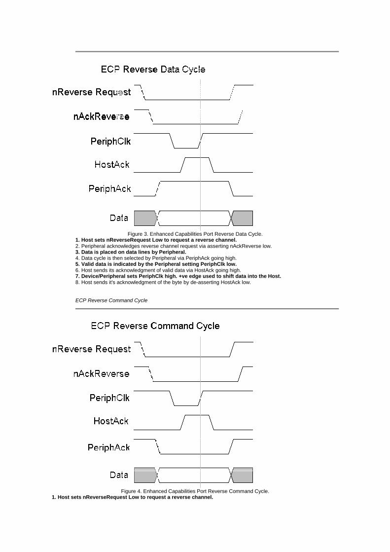
Figure 3. Enhanced Capabilities Port Reverse Data Cycle.1. Host sets nReverseRequest Low to request a reverse channel.2. Peripheral acknowledges reverse channel request via asserting nAckReverse low.3. Data is placed on data lines by Peripheral.4. Data cycle is then selected by Peripheral via PeriphAck going high.5. Valid data is indicated by the Peripheral setting PeriphClk low.6. Host sends its acknowledgment of valid data via HostAck going high.7. Device/Peripheral sets PeriphClk high. +ve edge used to shift data into the Host.8. Host sends it's acknowledgment of the byte by de-asserting HostAck low.
ECP Reverse Command Cycle
Figure 4. Enhanced Capabilities Port Reverse Command Cycle.1. Host sets nReverseRequest Low to request a reverse channel.

2. Peripheral acknowledges reverse channel request via asserting nAckReverse low.3. Data is placed on data lines by Peripheral.4. Command cycle is then selected by Peripheral via PeriphAck going low.5. Valid data is indicated by the Peripheral setting PeriphClk low.6. Host sends its acknowledgment of valid data via HostAck going high.7. Device/Peripheral sets PeriphClk high. +ve edge used to shift data into the Host.8. Host sends it's acknowledgment of the byte by de-asserting HostAck low.
EPP Handshake vs SPP Handshake
If we look back at the SPP Handshake you will realize it only has 5 steps,
1. Write the byte to the Data Port.2. Check to see is the printer is busy. If the printer is busy, it will not accept any data, thus any datawhich is written will be lost.3. Take the Strobe (Pin 1) low. This tells the printer that there is the correct data on the data lines.(Pins 2-9)4. Put the strobe high again after waiting approximately 5 microseconds after putting the strobe low.(Step 3)5. Check for Ack from Peripheral.
and that the ECP handshake has many more steps. This would suggest that ECP would be slower that SPP. However this isnot the case as all of these steps above are controlled by the hardware on your I/O control. If this handshake wasimplemented via software control then it would be a lot slower that it's SPP counterpart.
RLE - Run Length Encoding
As briefly discussed earlier, the ECP Protocol includes a Simple Compression Scheme called Run Length Encoding. It cansupport a maximum compression ratio of 64:1 and works by sending repetitive single bytes as a run count and one copy ofthe byte. The run count determines how many times the following byte is to be repeated.
For example, if a string of 25 'A's were to be sent, then a run count byte equal to 24 would be sent first, followed by the byte'A'. The receiving peripheral on receipt of the Run Length Count, would expand (Repeat) the next byte a number of timesdetermined via the run count.
The Run Length Byte has to be distinguished from other bytes in the Data Path. It is sent as a Command to the ECP'sAddress FIFO Port. Bytes sent to this register can be of two things, a Run Length Count or an Address. These aredistinguished by the MSB, Bit 7. If Bit 7 is Set (1), then the other 7 bits, bits 0 to 6 is a channel address. If Bit 7 is Reset (0),then the lower 7 bits is a run length count. By using the MSB, this limits channel Addresses and Run Length Counts to 7 Bits(0 - 127).
ECP Software Registers
The table below shows the registers of the Extended Capabilities Port. The first 3 registers are exactly the same than with theStandard Parallel Port registers. Note should be taken, however, of the Enable Bi-Directional Port bit (bit 5 of the ControlPort.) This bit reflects the direction that the ECP port is currently in, and will effect the FIFO Full and FIFO Empty bits ofthe ECR Register, which will be explained later.
AddressPort NameRead/Write
Base + 0Data Port (SPP)
Write
ECP Address FIFO (ECP MODE)Read/Write
Base + 1Status Port (All Modes)
Read/Write
Base + 2Control Port (All Modes)
Read/Write
Base + 400hData FIFO (Parallel Port FIFO Mode)
Read/Write
Data FIFO (ECP Mode)
Read/Write
Test FIFO (Test Mode)Read/Write
Configuration Register A (Configuration Mode)Read/Write
Base + 401hConfiguration Register B (Configuration Mode)
Read/Write
Base + 402hExtended Control Register (Used by all modes)
Read/Write
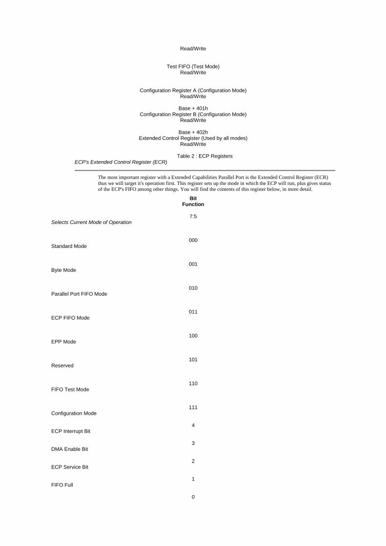
Table 2 : ECP RegistersECP's Extended Control Register (ECR)
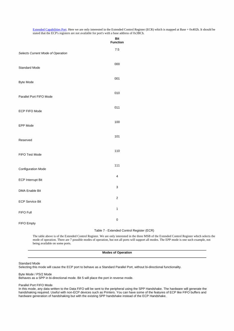
The most important register with a Extended Capabilities Parallel Port is the Extended Control Register (ECR)thus we will target it's operation first. This register sets up the mode in which the ECP will run, plus gives statusof the ECP's FIFO among other things. You will find the contents of this register below, in more detail.
BitFunction
7:5Selects Current Mode of Operation
000Standard Mode
001Byte Mode
010Parallel Port FIFO Mode
011ECP FIFO Mode
100EPP Mode
101Reserved
110FIFO Test Mode
111Configuration Mode
4ECP Interrupt Bit
3DMA Enable Bit
2ECP Service Bit
1FIFO Full
0

FIFO Empty
Table 3 ECR - Extended Control Register
The three MSB of the Extended Control Register selects the mode of operation. There are 7 possible modes ofoperation, but not all ports will support all modes. The EPP mode is one such example, not being available onsome ports. Below is a table of Modes of Operation.
Modes of Operation
Standard ModeSelecting this mode will cause the ECP port to behave as a Standard Parallel Port, without Bi-directional functionality.
Byte Mode / PS/2 ModeBehaves as a SPP in Bi-directional (Reverse) mode.
Parallel Port FIFO ModeIn this mode, any data written to the Data FIFO will be sent to the peripheral using the SPP Handshake. The hardware willgenerate the handshaking required. Useful with non-ECP devices such as Printers. You can have some of the features ofECP like FIFO buffers and hardware generation of handshaking but with the existing SPP handshake instead of theECP Handshake.
ECP FIFO ModeStandard Mode for ECP Use. This mode uses the ECP Handshake, already described.
EPP Mode/ReservedOn some chipsets, this mode will enable EPP to be used. While on others, this mode is still reserved.
ReservedCurrently Reserved
FIFO Test ModeWhile in this mode, any data written to the Test FIFO Register will be placed into the FIFO and any data read from the TestFIFO register will be read from the FIFO buffer. The FIFO Full/Empty Status Bits will reflect their true value, thus FIFOdepth, among other things can be determined in this mode.
Configuration ModeIn this mode, the two configuration registers, cnfgA & cnfgB become available at their designated Register Addresses.
As outlined above, when the port is set to operate in Standard Mode, it will behave just like a Standard ParallelPort (SPP) with no bi-directional data transfer. If you require bi-directional transfer, then set the mode to ByteMode. The Parallel Port FIFO mode and ECP FIFO mode both use hardware to generate the necessaryhandshaking signals. The only difference between each mode is that The Parallel Port FIFO Mode uses SPPhandshaking, thus can be used with your SPP printer. ECP FIFO mode uses ECP handshaking.
The FIFO test mode can be used to test the capacity of the FIFO Buffers as well as to make sure they functioncorrectly. When in FIFO test mode, any byte which is written to the TEST FIFO (Base + 400h) is placed into theFIFO buffer and any byte which is read from this register is taken from the FIFO Buffer. You can use this alongwith the FIFO Full and FIFO Empty bits of the Extended Control Register to determine the capacity of the FIFOBuffer. This should normally be about 16 Bytes deep.
The other Bits of the ECR also play an important role in the operation of the ECP Port. The ECP Interrupt Bit,(Bit 4) enables the use of Interrupts, while the DMA Enable Bit (Bit 3) enables the use of Direct Memory Access.The ECP Service Bit (Bit 2) shows if an interrupt request has been initiated. If so, this bit will be set. Resettingthis bit is different with different chips. Some require you to Reset the Bit, E.g. Write a Zero to it. Others willreset once the Register has been read.
The FIFO Full (Bit 1) and FIFO Empty (Bit 0) show the status of the FIFO Buffer. These bits are directiondependent, thus note should be taken of the Control Register's Bit 5. If bit 0 (FIFO Empty) is set, then the FIFObuffer is completely empty. If Bit 1 is set then the FIFO buffer is Full. Thus, if neither bit 0 or 1 is set, then thereis data in FIFO, but is not yet full. These bits can be used in FIFO Test Mode, to determine the capacity of theFIFO Buffer.
ECP's Configuration Register A (cnfgA)
Configuration Register A is one of two configuration registers which the ECP Port has. These ConfigurationRegisters are only accessible when the ECP Port is in Configuration Mode. (See Extended Control Register)CnfgA can be accessed at Base + 400h.
BitFunction

71
Interrupts are level triggered
0Interrupts are edge triggered (Pulses)
6:400h
Accepts Max. 16 Bit wide words
01hAccepts Max. 8 Bit wide words
02hAccepts Max. 32 Bit wide words
03h:07hReserved for future expansion
3Reserved
2Host Recovery : Pipeline/Transmitter Byte included in FIFO?
0In forward direction, the 1 byte in the transmitter pipeline doesn't affect FIFO Full.
1In forward direction, the 1 byte in the transmitter pipeline is include as part of FIFO Full.
1:0Host Recovery : Unsent byte(s) left in FIFO
00Complete Pword
011 Valid Byte
102 Valid Bytes
113 Valid Bytes
Table 4 - Configuration Register A
Configuration Register A can be read to find out a little more about the ECP Port. The MSB, shows if the cardgenerates level interrupts or edge triggered interrupts. This will depend upon the type of bus your card is using.Bits 4 to 6, show the buses width within the card. Some cards only have a 8 bit data path, while others may have a32 or 16 bit width. To get maximum efficiency from your card, the software can read the status of these bits todetermine the Maximum Word Size to output to the port.
The 3 LSB's are used for Host Recovery. In order to recover from an error, the software must know how manybytes were sent, by determining if there are any bytes left in the FIFO. Some implementations may include thebyte sitting in the transmitter register, waiting to be sent as part of the FIFO's Full Status, while others may not.Bit 2 determines weather or not this is the case.
The other problem is that the Parallel Ports output is only 8 bits wide, and that you many be using 16 bit or 32 bitI/O Instructions. If this is the case, then part of your Port Word (Word you sent to port) may be sent. ThereforeBits 0 and 1 give an indication of the number of valid bytes still left in the FIFO, so that you can retransmit these.
ECP's Configuration Register B (cnfgB)
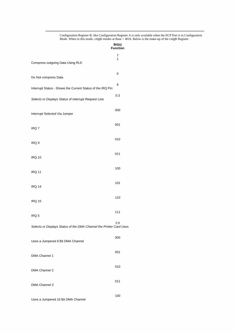
Configuration Register B, like Configuration Register A is only available when the ECP Port is in ConfigurationMode. When in this mode, cnfgB resides at Base + 401h. Below is the make-up of the cnfgB Register.
Bit(s)Function
71
Compress outgoing Data Using RLE
0Do Not compress Data
6Interrupt Status - Shows the Current Status of the IRQ Pin
5:3Selects or Displays Status of Interrupt Request Line.
000Interrupt Selected Via Jumper
001IRQ 7
010IRQ 9
011IRQ 10
100IRQ 11
101IRQ 14
110IRQ 15
111IRQ 5
2:0Selects or Displays Status of the DMA Channel the Printer Card Uses
000Uses a Jumpered 8 Bit DMA Channel
001DMA Channel 1
010DMA Channel 2
011DMA Channel 3
100Uses a Jumpered 16 Bit DMA Channel
101DMA Channel 5
110DMA Channel 6
111DMA Channel 7
Table 5 - Configuration B Register
The Configuration Register B (cnfgB) can be a combination of read/write access. Some ports may be softwareconfigurable, where you can set the IRQ and DMA resources from the register. Others may be set via BIOS or byusing jumpers on the Card, thus are read only.
Bit 7 of the cnfgB Register selects whether to compress outgoing data using RLE (Run Length Encoding.) WhenSet, the host will compress the data before sending. When reset, data will be sent to the peripheral raw(Uncompressed). Bit 6 returns the status of the IRQ pin. This can be used to diagnose conflicts as it will not onlyreflect the status of the Parallel Ports IRQ, but and other device using this IRQ.
Bits 5 to 3 give status of about the Port's IRQ assignment. Likewise for bits 2 to 0 which give status of DMAChannel assignment. As mentioned above these fields may be read/write. The disappearing species of ParallelCards which have Jumpers may simply show it's resources as "Jumpered" or it may show the correct LineNumbers. However these of course will be read only.
Copyright 1997-2001 Craig Peacock - 19th August 2001.
Hardware
Imagine you are looking at the back of your pc, and that the parallel port socket is horizontal, with the long row of socket on top. Thenumbers of the sockets at the ends of the rows are...
13 . . . . . . . . . . 1
25 . . . . . . 14
(See below for where things are to be found on the connector at the end of the cable normally plugged into a printer.) The 'interesting' pinsare:
Data bits 0-7: Pins 2 to 9, respectively. If you write to address 888 (decimal), you should see the outputs on those pins change. (The addressis different in some circumstances, but try 888. In Borland's Pascal: port[888]:=254 would set all bits but the first one high.)
Pins 18-25: Signal ground. (I.e. for a VERY simple experiment, connect an LED to pin2, a 680ohm resistor to the LED, and then the otherend of the LED to pin 19. If it doesn't work... try turning the LED around!)
Inputs: If you read address 889, you can discover the state of 5 pins. They determine the state of bits 3-7 of 889. bTmp:=port[889] is the 'raw'Pascal you need. Obviously, you do clever things with the result of that. The bits are mapped and named as follows:Bit Pin Name3 15 Error4 13 Select In5 12 Paper Empty6 10 Acknowledge7 11 Busy(A trap for the unwary... 'Busy' is inverted 'just inside' the computer. Thus if you apply a '1' to all of the pins, you'll see 01111xxx when youread 889! Isn't computing fun?)
Before turning to more generally useful things, I might as well finish off the other pins....
Write to 890 to set the state of the following pins:Bit Pin Name0 1 Strobe1 14 Auto Linefeed2 16 Initialise3 17 Select Out

Monday, June 10th, 2002
Universal Serial Bus Embedded Linux Legacy Ports Device Drivers Miscellaneous
Interfacing the Standard Parallel Port
Table of Contents
Introduction to Parallel PortsHardware Properties
Centronics?Port Addresses
Software Registers - Standard Parallel Port (SPP)Bi-directional Ports
Using the Parallel Port to Input 8 BitsNibble Mode
Using the Parallel Port's IRQParallel Port Modes in BIOS
Parallel Port Modes and the ECP's Extended Control RegisterPDF Version
Introduction to Parallel Ports
The Parallel Port is the most commonly used port for interfacing home made projects. This port will allow the input of up to 9 bits or the outputof 12 bits at any one given time, thus requiring minimal external circuitry to implement many simpler tasks. The port is composed of 4 controllines, 5 status lines and 8 data lines. It's found commonly on the back of your PC as a D-Type 25 Pin female connector. There may also be a D-Type 25 pin male connector. This will be a serial RS-232 port and thus, is a totally incompatible port.
For more information on Serial RS-232 Ports See http://www.beyondlogic.org/serial/serial.htm
Newer Parallel Port’s are standardized under the IEEE 1284 standard first released in 1994. This standard defines 5 modes of operation whichare as follows,
1. Compatibility Mode.2. Nibble Mode. (Protocol not Described in this Document)3. Byte Mode. (Protocol not Described in this Document)4. EPP Mode (Enhanced Parallel Port).5. ECP Mode (Extended Capabilities Mode).
The aim was to design new drivers and devices which were compatible with each other and also backwards compatible with the StandardParallel Port (SPP). Compatibility, Nibble & Byte modes use just the standard hardware available on the original Parallel Port cards while EPP& ECP modes require additional hardware which can run at faster speeds, while still being downwards compatible with the Standard ParallelPort.
Compatibility mode or "Centronics Mode" as it is commonly known, can only send data in the forward direction at a typical speed of 50 kbytesper second but can be as high as 150+ kbytes a second. In order to receive data, you must change the mode to either Nibble or Byte mode.Nibble mode can input a nibble (4 bits) in the reverse direction. E.g. from device to computer. Byte mode uses the Parallel's bi-directionalfeature (found only on some cards) to input a byte (8 bits) of data in the reverse direction.
Extended and Enhanced Parallel Ports use additional hardware to generate and manage handshaking. To output a byte to a printer(or anything in that matter) using compatibility mode, the software must,
1. Write the byte to the Data Port.2. Check to see is the printer is busy. If the printer is busy, it will not accept any data, thus any data which is written willbe lost.3. Take the Strobe (Pin 1) low. This tells the printer that there is the correct data on the data lines. (Pins 2-9)4. Put the strobe high again after waiting approximately 5 microseconds after putting the strobe low. (Step 3)
This limits the speed at which the port can run at. The EPP & ECP ports get around this by letting the hardware check to see if the printer is busyand generate a strobe and /or appropriate handshaking. This means only one I/O instruction need to be performed, thus increasing the speed.These ports can output at around 1-2 megabytes per second. The ECP port also has the advantage of using DMA channels and FIFO buffers,thus data can be shifted around without using I/O instructions.
Hardware Properties
Below is a table of the "Pin Outs" of the D-Type 25 Pin connector and the Centronics 34 Pin connector. The D-Type 25 pin connector is themost common connector found on the Parallel Port of the computer, while the Centronics Connector is commonly found on printers. The IEEE1284 standard however specifies 3 different connectors for use with the Parallel Port. The first one, 1284 Type A is the D-Type 25 connectorfound on the back of most computers. The 2nd is the 1284 Type B which is the 36 pin Centronics Connector found on most printers.
IEEE 1284 Type C however, is a 36 conductor connector like the Centronics, but smaller. This connector is claimed to have a better clip latch,better electrical properties and is easier to assemble. It also contains two more pins for signals which can be used to see whether the other deviceconnected, has power. 1284 Type C connectors are recommended for new designs, so we can look forward on seeing these new connectors in

the near future.
Pin No (D-Type 25)Pin No (Centronics)
SPP SignalDirection In/out
RegisterHardware Inverted
11
nStrobeIn/OutControl
Yes
22
Data 0OutData
33
Data 1OutData
44
Data 2OutData
55
Data 3OutData
66
Data 4OutData
77
Data 5OutData
88
Data 6OutData
99
Data 7OutData
1010
nAckIn
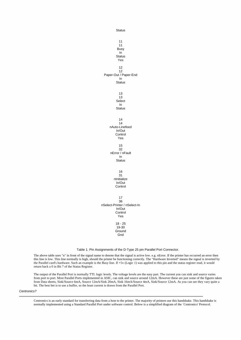
Status
1111
BusyIn
StatusYes
1212
Paper-Out / Paper-EndIn
Status
1313
SelectIn
Status
1414
nAuto-LinefeedIn/OutControl
Yes
1532
nError / nFaultIn
Status
1631
nInitializeIn/OutControl
1736
nSelect-Printer / nSelect-InIn/OutControl
Yes
18 - 2519-30
GroundGnd
Table 1. Pin Assignments of the D-Type 25 pin Parallel Port Connector.
The above table uses "n" in front of the signal name to denote that the signal is active low. e.g. nError. If the printer has occurred an error thenthis line is low. This line normally is high, should the printer be functioning correctly. The "Hardware Inverted" means the signal is inverted bythe Parallel card's hardware. Such an example is the Busy line. If +5v (Logic 1) was applied to this pin and the status register read, it wouldreturn back a 0 in Bit 7 of the Status Register.
The output of the Parallel Port is normally TTL logic levels. The voltage levels are the easy part. The current you can sink and source variesfrom port to port. Most Parallel Ports implemented in ASIC, can sink and source around 12mA. However these are just some of the figures takenfrom Data sheets, Sink/Source 6mA, Source 12mA/Sink 20mA, Sink 16mA/Source 4mA, Sink/Source 12mA. As you can see they vary quite abit. The best bet is to use a buffer, so the least current is drawn from the Parallel Port.
Centronics?
Centronics is an early standard for transferring data from a host to the printer. The majority of printers use this handshake. This handshake isnormally implemented using a Standard Parallel Port under software control. Below is a simplified diagram of the `Centronics' Protocol.
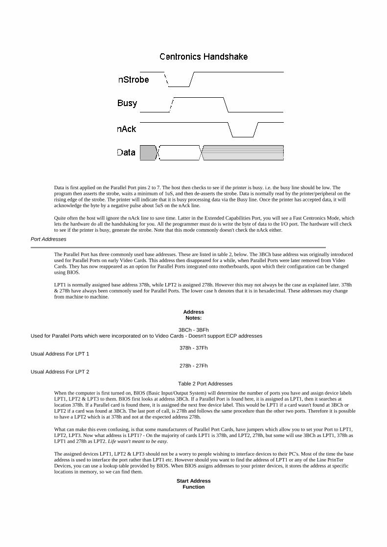
Data is first applied on the Parallel Port pins 2 to 7. The host then checks to see if the printer is busy. i.e. the busy line should be low. Theprogram then asserts the strobe, waits a minimum of 1uS, and then de-asserts the strobe. Data is normally read by the printer/peripheral on therising edge of the strobe. The printer will indicate that it is busy processing data via the Busy line. Once the printer has accepted data, it willacknowledge the byte by a negative pulse about 5uS on the nAck line.
Quite often the host will ignore the nAck line to save time. Latter in the Extended Capabilities Port, you will see a Fast Centronics Mode, whichlets the hardware do all the handshaking for you. All the programmer must do is write the byte of data to the I/O port. The hardware will checkto see if the printer is busy, generate the strobe. Note that this mode commonly doesn't check the nAck either.
Port Addresses
The Parallel Port has three commonly used base addresses. These are listed in table 2, below. The 3BCh base address was originally introducedused for Parallel Ports on early Video Cards. This address then disappeared for a while, when Parallel Ports were later removed from VideoCards. They has now reappeared as an option for Parallel Ports integrated onto motherboards, upon which their configuration can be changedusing BIOS.
LPT1 is normally assigned base address 378h, while LPT2 is assigned 278h. However this may not always be the case as explained later. 378h& 278h have always been commonly used for Parallel Ports. The lower case h denotes that it is in hexadecimal. These addresses may changefrom machine to machine.
AddressNotes:
3BCh - 3BFhUsed for Parallel Ports which were incorporated on to Video Cards - Doesn't support ECP addresses
378h - 37FhUsual Address For LPT 1
278h - 27FhUsual Address For LPT 2
Table 2 Port Addresses
When the computer is first turned on, BIOS (Basic Input/Output System) will determine the number of ports you have and assign device labelsLPT1, LPT2 & LPT3 to them. BIOS first looks at address 3BCh. If a Parallel Port is found here, it is assigned as LPT1, then it searches atlocation 378h. If a Parallel card is found there, it is assigned the next free device label. This would be LPT1 if a card wasn't found at 3BCh orLPT2 if a card was found at 3BCh. The last port of call, is 278h and follows the same procedure than the other two ports. Therefore it is possibleto have a LPT2 which is at 378h and not at the expected address 278h.
What can make this even confusing, is that some manufacturers of Parallel Port Cards, have jumpers which allow you to set your Port to LPT1,LPT2, LPT3. Now what address is LPT1? - On the majority of cards LPT1 is 378h, and LPT2, 278h, but some will use 3BCh as LPT1, 378h asLPT1 and 278h as LPT2. Life wasn't meant to be easy.
The assigned devices LPT1, LPT2 & LPT3 should not be a worry to people wishing to interface devices to their PC's. Most of the time the baseaddress is used to interface the port rather than LPT1 etc. However should you want to find the address of LPT1 or any of the Line PrinTerDevices, you can use a lookup table provided by BIOS. When BIOS assigns addresses to your printer devices, it stores the address at specificlocations in memory, so we can find them.
Start AddressFunction

0000:0408LPT1's Base Address
0000:040ALPT2's Base Address
0000:040CLPT3's Base Address
0000:040ELPT4's Base Address (Note 1)
Table 3 - LPT Addresses in the BIOS Data Area;
Note 1 : Address 0000:040E in the BIOS Data Area may be used as the Extended Bios Data Area in PS/2 and newer Bioses.
The above table, table 3, shows the address at which we can find the Printer Port's addresses in the BIOS Data Area. Each address will take up 2bytes. The following sample program in C, shows how you can read these locations to obtain the addresses of your printer ports.
#include <stdio.h>#include <dos.h>
void main(void){ unsigned int far *ptraddr; /* Pointer to location of Port Addresses */ unsigned int address; /* Address of Port */ int a;
ptraddr=(unsigned int far *)0x00000408;
for (a = 0; a < 3; a++) { address = *ptraddr; if (address == 0)
printf("No port found for LPT%d \n",a+1); else
printf("Address assigned to LPT%d is %Xh\n",a+1,address); *ptraddr++; }}
Software Registers - Standard Parallel Port (SPP)
OffsetName
Read/WriteBit No.
Properties
Base + 0Data Port
Write (Note-1)Bit 7
Data 7
Bit 6Data 6
Bit 5Data 5
Bit 4Data 4
Bit 3Data 3

Bit 2Data 2
Bit 1Data 1
Bit 0Data 0
Table 4 Data Port
Note 1 : If the Port is Bi-Directional then Read and Write Operations can be performed on the Data Register.
The base address, usually called the Data Port or Data Register is simply used for outputting data on the Parallel Port's data lines (Pins 2-9). Thisregister is normally a write only port. If you read from the port, you should get the last byte sent. However if your port is bi-directional, you canreceive data on this address. See Bi-directional Ports for more detail.
OffsetName
Read/WriteBit No.
Properties
Base + 1Status PortRead Only
Bit 7Busy
Bit 6Ack
Bit 5Paper Out
Bit 4Select In
Bit 3Error
Bit 2IRQ (Not)
Bit 1Reserved

Bit 0Reserved
Table 5 Status Port
The Status Port (base address + 1) is a read only port. Any data written to this port will be ignored. The Status Port is made up of 5 input lines(Pins 10,11,12,13 & 15), a IRQ status register and two reserved bits. Please note that Bit 7 (Busy) is a active low input. E.g. If bit 7 happens toshow a logic 0, this means that there is +5v at pin 11. Likewise with Bit 2. (nIRQ) If this bit shows a '1' then an interrupt has not occurred.
OffsetName
Read/WriteBit No.
Properties
Base + 2Control PortRead/Write
Bit 7Unused
Bit 6Unused
Bit 5Enable Bi-Directional Port
Bit 4Enable IRQ Via Ack Line
Bit 3Select Printer
Bit 2Initialize Printer (Reset)
Bit 1Auto Linefeed
Bit 0Strobe
Table 6 Control Port
The Control Port (base address + 2) was intended as a write only port. When a printer is attached to the Parallel Port, four "controls" are used.These are Strobe, Auto Linefeed, Initialize and Select Printer, all of which are inverted except Initialize.
The printer would not send a signal to initialize the computer, nor would it tell the computer to use auto linefeed. However these four outputs canalso be used for inputs. If the computer has placed a pin high (e.g. +5v) and your device wanted to take it low, you would effectively short outthe port, causing a conflict on that pin. Therefore these lines are "open collector" outputs (or open drain for CMOS devices). This means that ithas two states. A low state (0v) and a high impedance state (open circuit).
Normally the Printer Card will have internal pull-up resistors, but as you would expect, not all will. Some may just have open collector outputs,while others may even have normal totem pole outputs. In order to make your device work correctly on as many Printer Ports as possible, youcan use an external resistor as well. Should you already have an internal resistor, then it will act in Parallel with it, or if you have Totem pole

outputs, the resistor will act as a load.
An external 4.7k resistor can be used to pull the pin high. I wouldn't use anything lower, just in case you do have an internal pull up resistor, asthe external resistor would act in parallel giving effectively, a lower value pull up resistor. When in high impedance state the pin on the ParallelPort is high (+5v). When in this state, your external device can pull the pin low and have the control port change read a different value. This waythe 4 pins of the Control Port can be used for bi-directional data transfer. However the Control Port must be set to xxxx0100 to be able to readdata, that is all pins to be +5v at the port so that you can pull it down to GND (logic 0).
Bits 4 & 5 are internal controls. Bit four will enable the IRQ (See Using the Parallel Ports IRQ) and Bit 5 will enable the bi-directional portmeaning that you can input 8 bits using (DATA0-7). This mode is only possible if your card supports it. Bits 6 & 7 are reserved. Any writes tothese two bits will be ignored.
Bi-directional Ports
The schematic diagram below, shows a simplified view of the Parallel Port's Data Register. The original Parallel Port card's implemented 74LSlogic. These days all this is crammed into one ASIC, but the theory of operation is still the same.
The non bi-directional ports were manufactured with the 74LS374's output enable tied permanent low, thus the data port is always output only.When you read the Parallel Port's data register, the data comes from the 74LS374 which is also connected to the data pins. Now if you canoverdrive the '374 you can effectively have a Bi-directional Port. (or a input only port, once you blow up the latches output!)
What is very concerning is that people have actually done this. I've seen one circuit, a scope connected to the Parallel Port distributed on theInternet. The author uses an ADC of some type, but finds the ADC requires transistors on each data line, to make it work! No wonder why.Others have had similar trouble, the 68HC11 cannot sink enough current (30 to 40mA!)
Bi-directional ports use Control Bit 5 connected to the 374's Output Enable so that it's output drivers can be turned off. This way you can readdata present on the Parallel Port's Data Pins, without having bus conflicts and excessive current drains.
Bit 5 of the Control Port enables or disables the bi-directional function of the Parallel Port. This is only available on true bi-directional ports.When this bit is set to one, pins 2 to 9 go into high impedance state. Once in this state you can enter data on these lines and retrieve it from theData Port (base address). Any data which is written to the data port will be stored but will not be available at the data pins. To turn off bi-directional mode, set bit 5 of the Control Port to '0'.
However not all ports behave in the same way. Other ports may require setting bit 6 of the Control Port to enable Bi-directional mode and settingof Bit 5 to dis-enable Bi-directional mode, Different manufacturers implement their bi-directional ports in different ways. If you wish to use yourBi-directional port to input data, test it with a logic probe or multimeter first to make sure it is in bi-directional mode.
Using The Parallel Port to Input 8 Bits.
If your Parallel Port doesn't support bi-directional mode, don't despair. You can input a maximum of 9 bits at any one given time. To do this you
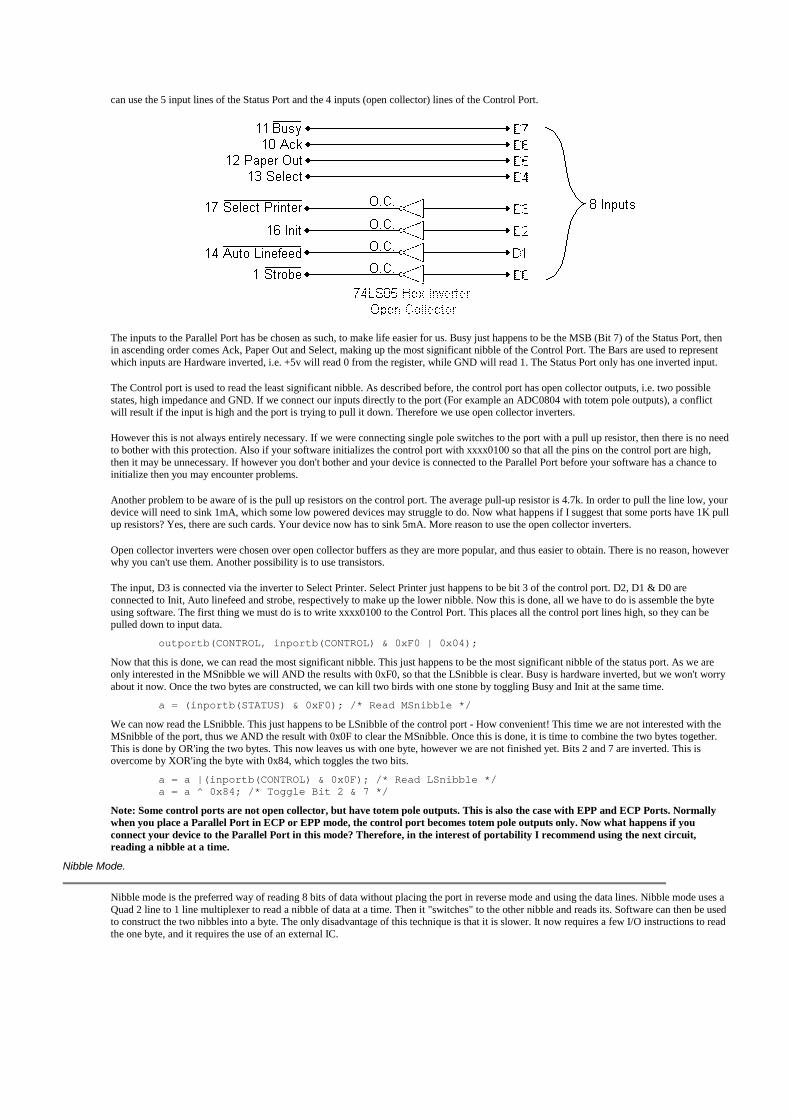
can use the 5 input lines of the Status Port and the 4 inputs (open collector) lines of the Control Port.
The inputs to the Parallel Port has be chosen as such, to make life easier for us. Busy just happens to be the MSB (Bit 7) of the Status Port, thenin ascending order comes Ack, Paper Out and Select, making up the most significant nibble of the Control Port. The Bars are used to representwhich inputs are Hardware inverted, i.e. +5v will read 0 from the register, while GND will read 1. The Status Port only has one inverted input.
The Control port is used to read the least significant nibble. As described before, the control port has open collector outputs, i.e. two possiblestates, high impedance and GND. If we connect our inputs directly to the port (For example an ADC0804 with totem pole outputs), a conflictwill result if the input is high and the port is trying to pull it down. Therefore we use open collector inverters.
However this is not always entirely necessary. If we were connecting single pole switches to the port with a pull up resistor, then there is no needto bother with this protection. Also if your software initializes the control port with xxxx0100 so that all the pins on the control port are high,then it may be unnecessary. If however you don't bother and your device is connected to the Parallel Port before your software has a chance toinitialize then you may encounter problems.
Another problem to be aware of is the pull up resistors on the control port. The average pull-up resistor is 4.7k. In order to pull the line low, yourdevice will need to sink 1mA, which some low powered devices may struggle to do. Now what happens if I suggest that some ports have 1K pullup resistors? Yes, there are such cards. Your device now has to sink 5mA. More reason to use the open collector inverters.
Open collector inverters were chosen over open collector buffers as they are more popular, and thus easier to obtain. There is no reason, howeverwhy you can't use them. Another possibility is to use transistors.
The input, D3 is connected via the inverter to Select Printer. Select Printer just happens to be bit 3 of the control port. D2, D1 & D0 areconnected to Init, Auto linefeed and strobe, respectively to make up the lower nibble. Now this is done, all we have to do is assemble the byteusing software. The first thing we must do is to write xxxx0100 to the Control Port. This places all the control port lines high, so they can bepulled down to input data.
outportb(CONTROL, inportb(CONTROL) & 0xF0 | 0x04);
Now that this is done, we can read the most significant nibble. This just happens to be the most significant nibble of the status port. As we areonly interested in the MSnibble we will AND the results with 0xF0, so that the LSnibble is clear. Busy is hardware inverted, but we won't worryabout it now. Once the two bytes are constructed, we can kill two birds with one stone by toggling Busy and Init at the same time.
a = (inportb(STATUS) & 0xF0); /* Read MSnibble */
We can now read the LSnibble. This just happens to be LSnibble of the control port - How convenient! This time we are not interested with theMSnibble of the port, thus we AND the result with 0x0F to clear the MSnibble. Once this is done, it is time to combine the two bytes together.This is done by OR'ing the two bytes. This now leaves us with one byte, however we are not finished yet. Bits 2 and 7 are inverted. This isovercome by XOR'ing the byte with 0x84, which toggles the two bits.
a = a |(inportb(CONTROL) & 0x0F); /* Read LSnibble */a = a ^ 0x84; /* Toggle Bit 2 & 7 */
Note: Some control ports are not open collector, but have totem pole outputs. This is also the case with EPP and ECP Ports. Normallywhen you place a Parallel Port in ECP or EPP mode, the control port becomes totem pole outputs only. Now what happens if youconnect your device to the Parallel Port in this mode? Therefore, in the interest of portability I recommend using the next circuit,reading a nibble at a time.
Nibble Mode.
Nibble mode is the preferred way of reading 8 bits of data without placing the port in reverse mode and using the data lines. Nibble mode uses aQuad 2 line to 1 line multiplexer to read a nibble of data at a time. Then it "switches" to the other nibble and reads its. Software can then be usedto construct the two nibbles into a byte. The only disadvantage of this technique is that it is slower. It now requires a few I/O instructions to readthe one byte, and it requires the use of an external IC.

The operation of the 74LS157, Quad 2 line to 1 line multiplexer is quite simple. It simply acts as four switches. When the A/B input is low, theA inputs are selected. E.g. 1A passes through to 1Y, 2A passes through to 2Y etc. When the A/B is high, the B inputs are selected. The Youtputs are connected up to the Parallel Port's status port, in such a manner that it represents the MSnibble of the status register. While this is notnecessary, it makes the software easier.
To use this circuit, first we must initialize the multiplexer to switch either inputs A or B. We will read the LSnibble first, thus we must place A/Blow. The strobe is hardware inverted, thus we must set Bit 0 of the control port to get a low on Pin 1.
outportb(CONTROL, inportb(CONTROL) | 0x01); /* Select Low Nibble (A)*/
Once the low nibble is selected, we can read the LSnibble from the Status Port. Take note that the Busy Line is inverted, however we won'ttackle it just yet. We are only interested in the MSnibble of the result, thus we AND the result with 0xF0, to clear the LSnibble.
a = (inportb(STATUS) & 0xF0); /* Read Low Nibble */
Now it's time to shift the nibble we have just read to the LSnibble of variable a,
a = a >> 4; /* Shift Right 4 Bits */
We are now half way there. It's time to get the MSnibble, thus we must switch the multiplexer to select inputs B. Then we can read the MSnibbleand put the two nibbles together to make a byte,
outportb(CONTROL, inportb(CONTROL) & 0xFE); /* Select High Nibble (B)*/a = a |(inportb(STATUS) & 0xF0); /* Read High Nibble */byte = byte ^ 0x88;
The last line toggles two inverted bits which were read in on the Busy line. It may be necessary to add delays in the process, if the incorrectresults are being returned.
Using the Parallel Port's IRQ
The Parallel Port's interrupt request is not used for printing under DOS or Windows. Early versions of OS-2 used them, but don't anymore.Interrupts are good when interfacing monitoring devices such as high temp alarms etc, where you don't know when it is going to be activated. It'smore efficient to have an interrupt request rather than have the software poll the ports regularly to see if something has changed. This is evenmore noticeable if you are using your computer for other tasks, such as with a multitasking operating system.
The Parallel Port's interrupt request is normally IRQ5 or IRQ7 but may be something else if these are in use. It may also be possible that theinterrupts are totally disabled on the card, if the card was only used for printing. The Parallel Port interrupt can be disabled and enabled using bit4 of the control register, Enable IRQ Via Ack Line. Once enabled, an interrupt will occur upon a low to high transition (rising edge) of thenACK. However like always, some cards may trigger the interrupt on the high to low transition.
The following code is an Interrupt Polarity Tester, which serves as two things. It will determine which polarity your Parallel Port interrupt is,while also giving you an example for how to use the Parallel Port's Interrupt. It checks if your interrupt is generated on the rising or falling edgeof the nACK line. To use the program simply wire one of the Data lines (Pins 2 to 9) to the Ack Pin (Pin 10). The easiest way to do this is tobridge some solder from DATA7 (Pin 9) to ACK (Pin 10) on a male DB25 connector.
/* Parallel Port Interrupt Polarity Tester *//* 2nd February 1998 *//* Copyright 1997 Craig Peacock *//* WWW - http://www.beyondlogic.org *//* Email - [email protected] */

#include <dos.h>
#define PORTADDRESS 0x378 /* Enter Your Port Address Here */#define IRQ 7 /* IRQ Here */
#define DATA PORTADDRESS+0#define STATUS PORTADDRESS+1#define CONTROL PORTADDRESS+2
#define PIC1 0x20#define PIC2 0xA0
int interflag; /* Interrupt Flag */int picaddr; /* Programmable Interrupt Controller (PIC) Base Address */
void interrupt (*oldhandler)();
void interrupt parisr() /* Interrupt Service Routine (ISR) */{ interflag = 1; outportb(picaddr,0x20); /* End of Interrupt (EOI) */}
void main(void){ int c; int intno; /* Interrupt Vector Number */ int picmask; /* PIC's Mask */
/* Calculate Interrupt Vector, PIC Addr & Mask. */
if (IRQ >= 2 && IRQ <= 7) { intno = IRQ + 0x08; picaddr = PIC1; picmask = 1;
picmask = picmask << IRQ; }
if (IRQ >= 8 && IRQ <= 15) { intno = IRQ + 0x68; picaddr = PIC2; picmask = 1;
picmask = picmask << (IRQ-8); }
if (IRQ < 2 || IRQ > 15){ printf("IRQ Out of Range\n"); exit();}
outportb(CONTROL, inportb(CONTROL) & 0xDF); /* Make sure port is in Forward Direction */ outportb(DATA,0xFF); oldhandler = getvect(intno); /* Save Old Interrupt Vector */ setvect(intno, parisr); /* Set New Interrupt Vector Entry */ outportb(picaddr+1,inportb(picaddr+1) & (0xFF - picmask)); /* Un-Mask Pic */ outportb(CONTROL, inportb(CONTROL) | 0x10); /* Enable Parallel Port IRQ's */
clrscr(); printf("Parallel Port Interrupt Polarity Tester\n"); printf("IRQ %d : INTNO %02X : PIC Addr 0x%X : Mask 0x%02X\n",IRQ,intno,picaddr,picmask); interflag = 0; /* Reset Interrupt Flag */ delay(10); outportb(DATA,0x00); /* High to Low Transition */ delay(10); /* Wait */ if (interflag == 1) printf("Interrupts Occur on High to Low Transition of ACK.\n"); else { outportb(DATA,0xFF); /* Low to High Transition */ delay(10); /* wait */ if (interflag == 1) printf("Interrupts Occur on Low to High Transition of ACK.\n"); else printf("No Interrupt Activity Occurred. \nCheck IRQ Number, Port Address andWiring."); }
outportb(CONTROL, inportb(CONTROL) & 0xEF); /* Disable Parallel Port IRQ's */ outportb(picaddr+1,inportb(picaddr+1) | picmask); /* Mask Pic */ setvect(intno, oldhandler); /* Restore old Interrupt Vector Before Exit */}
At compile time, the above source may generate a few warnings, condition always true, condition always false, unreachable code etc. These areperfectly O.K. They are generated as some of the condition structures test which IRQ you are using, and as the IRQ is defined as a constant someoutcomes will never change. While they would of been better implemented as a preprocessor directive, I've done this so you can cut and pastethe source code in your own programs which may use command line arguments, user input etc instead of a defined IRQ.
To understand how this example works, the reader must have an assumed knowledge and understanding of Interrupts and Interrupt ServiceRoutines (ISR). If not, See Interfacing the PC : Using Interrupts for a quick introduction.
The first part of the mainline routine calculates the Interrupt Vector, PIC Addr & Mask in order to use the Parallel Port's Interrupt Facility. Afterthe Interrupt Service Routine (ISR) has been set up and the Programmable Interrupt Controller (PIC) set, we must enable the interrupt on theParallel Port. This is done by setting bit 4 of the Parallel Port's Control Register using
outportb(CONTROL,inportb(CONTROL) | 0x10);
Before enabling the interrupts, we wrote 0xFF to the Parallel Port to enable the 8 data lines into a known state. At this point of the program, allthe data lines should be high. The interrupt service routine simply sets a flag (interflag), thus we can determine when an IRQ occurs. We are nowin a position to write 0x00 to the data port, which causes a high to low transition on the Parallel Port's Acknowledge line as it's connected to oneof the data lines.
If the interrupt occurs on the high to low transition, the interrupt flag (interflag) should be set. We now test this, and if this is so the programinforms the user. However if it is not set, then an interrupt has not yet occurred. We now write 0xFF to the data port, which will cause a low tohigh transition on the nAck line and check the interrupt flag again. If set, then the interrupt occurs on the low to high transition.
However if the interrupt flag is still reset, then this would suggest that the interrupts are not working. Make sure your IRQ and Base Address iscorrect and also check the wiring of the plug.
Parallel Port Modes in BIOS
Today, most Parallel Ports are mulimode ports. They are normally software configurable to one of many modes from BIOS. The typical modesare,
Printer Mode (Sometimes called Default or Normal Modes)Standard & Bi-directional (SPP) ModeEPP1.7 and SPP ModeEPP1.9 and SPP ModeECP ModeECP and EPP1.7 ModeECP and EPP1.9 Mode
Printer Mode is the most basic mode. It is a Standard Parallel Port in forward mode only. It has no bi-directional feature, thus Bit 5 of theControl Port will not respond. Standard & Bi-directional (SPP) Mode is the bi-directional mode. Using this mode, bit 5 of the Control Port willreverse the direction of the port, so you can read back a value on the data lines.
EPP1.7 and SPP Mode is a combination of EPP 1.7 (Enhanced Parallel Port) and SPP Modes. In this mode of operation you will have access tothe SPP registers (Data, Status and Control) and access to the EPP Registers. In this mode you should be able to reverse the direction of the portusing bit 5 of the control register. EPP 1.7 is the earlier version of EPP. This version, version 1.7, may not have the time-out bit. See Interfacingthe Enhanced Parallel Port for more information.
EPP1.9 and SPP Mode is just like the previous mode, only it uses EPP Version 1.9 this time. As in the other mode, you will have access to theSPP registers, including Bit 5 of the control port. However this differs from EPP1.7 and SPP Mode as you should have access to the EPPTimeout bit.
ECP Mode will give you an Extended Capabilities Port. The mode of this port can then be set using the ECP's Extended Control Register (ECR).However in this mode from BIOS the EPP Mode (100) will not be available. We will further discuss the ECP's Extended Control Register in thisdocument, but if you want further information on the ECP port, consult Interfacing the Extended Capabilities Port.
ECP and EPP1.7 Mode and ECP and EPP1.9 Mode will give you an Extended Capabilities Port, just like the previous mode. However the EPPMode in the ECP's ECR will now be available. Should you be in ECP and EPP1.7 Mode you will get an EPP1.7 Port, or if you are in ECP andEPP1.9 Mode, an EPP1.9 Port will be at your disposal.
The above modes are configurable via BIOS. You can reconfigure them by using your own software, but this is not recommended. Thesesoftware registers, typically found at 0x2FA, 0x3F0, 0x3F1 etc are only intended to be accessed by BIOS. There is no set standard for theseconfiguration registers, thus if you were to use these registers, your software would not be very portable. With today's multitasking operatingsystems, its also not a good idea to change them when it suits you.
A better option is to select ECP and EPP1.7 Mode or ECP and EPP1.9 Mode from BIOS and then use the ECP's Extended Control Register toselect your Parallel Port's Mode. The EPP1.7 mode had a few problems in regards to the Data and Address Strobes being asserted to start a cycleregardless of the wait state, thus this mode if not typically used now. Best set your Parallel Port to ECP and EPP1.9 Mode.
Parallel Port Modes and the ECP's Extended Control Register
As we have just discussed, it is better to set the Parallel Port to ECP and EPP1.9 Mode and use the ECP's Extended Control Register to selectdifferent modes of operation. The ECP Registers are standardized under Microsoft's Extended Capabilities Port Protocol and ISA InterfaceStandard, thus we don't have that problem of every vendor having their own register set.
When set to ECP Mode, a new set of registers become available at Base + 0x400h. A discussion of these registers are available in Interfacing the
Extended Capabilities Port. Here we are only interested in the Extended Control Register (ECR) which is mapped at Base + 0x402h. It should bestated that the ECP's registers are not available for port's with a base address of 0x3BCh.
BitFunction
7:5Selects Current Mode of Operation
000Standard Mode
001Byte Mode
010Parallel Port FIFO Mode
011ECP FIFO Mode
100EPP Mode
101Reserved
110FIFO Test Mode
111Configuration Mode
4ECP Interrupt Bit
3DMA Enable Bit
2ECP Service Bit
1FIFO Full
0FIFO Empty
Table 7 - Extended Control Register (ECR)
The table above is of the Extended Control Register. We are only interested in the three MSB of the Extended Control Register which selects themode of operation. There are 7 possible modes of operation, but not all ports will support all modes. The EPP mode is one such example, notbeing available on some ports.
Modes of Operation
Standard ModeSelecting this mode will cause the ECP port to behave as a Standard Parallel Port, without bi-directional functionality.
Byte Mode / PS/2 ModeBehaves as a SPP in bi-directional mode. Bit 5 will place the port in reverse mode.
Parallel Port FIFO ModeIn this mode, any data written to the Data FIFO will be sent to the peripheral using the SPP Handshake. The hardware will generate thehandshaking required. Useful with non-ECP devices such as Printers. You can have some of the features of ECP like FIFO buffers andhardware generation of handshaking but with the existing SPP handshake instead of the ECP Handshake.

ECP FIFO ModeStandard mode for ECP use. This mode uses the ECP Handshake described in Interfacing the Extended Capabilities Port. - When in ECPMode though BIOS, and the ECR register is set to ECP FIFO Mode (011), the SPP registers may disappear.
EPP Mode/ReservedThis will enable EPP Mode, if available. Under BIOS, if ECP mode is set then it's more than likely, this mode is not an option. However ifBIOS is set to ECP and EPP1.x Mode, then EPP 1.x will be enabled. - Under Microsoft's Extended Capabilities Port Protocol and ISAInterface Standard this mode is Vendor Specified.
ReservedCurrently Reserved. - Under Microsoft's Extended Capabilities Port Protocol and ISA Interface Standard this mode is Vendor Specified.
FIFO Test ModeWhile in this mode, any data written to the Test FIFO Register will be placed into the FIFO and any data read from the Test FIFO register willbe read from the FIFO buffer. The FIFO Full/Empty Status Bits will reflect their true value, thus FIFO depth, among other things can bedetermined in this mode.
Configuration ModeIn this mode, the two configuration registers, cnfgA & cnfgB become available at their designated register addresses.
If you are in ECP Mode under BIOS, or if your card is jumpered to use ECP then it is a good idea to initialize the mode of your ECP port to apre-defined state before use. If you are using SPP, then set the port to Standard Mode as the first thing you do. Don't assume that the port willalready be in Standard (SPP) mode.
Under some of the modes, the SPP registers may disappear or not work correctly. If you are using SPP, then set the ECR to Standard Mode. Thisis one of the most common mistakes that people make.
PDF Version
This page, Interfacing the Standard Parallel Port is also avaliable in PDF (Portable Document Format),
Interfacing the Standard Parallel Port (76KB)
Copyright 1999-2001 Craig Peacock 19th August 2001.
Kris Heidenstrom's PC Parallel Port Mini-FAQ
By Kris Heidenstrom ([email protected])
Release 11, 02 April 2000
This is a concise Mini-FAQ with basic information on the standard and PS/2-bidirectional PC parallel ports. As of release 9 this documentexists in HTML format only. Please send any comments, corrections and suggestions to [email protected].
In no event shall the author be liable for any damages whatsoever for any loss relating to this document. Use it at your own risk!
Introduction
A parallel port links software to the real world. To software, the parallel port is three 8-bit registers occupying three consecutive addresses inthe I/O space. To hardware, the port is a female 25-pin D-sub connector, carrying twelve latched outputs from the computer, accepting fiveinputs into the computer, with eight ground lines (pins 18-25). Here is the pinout.
The normal function of the port is to transfer data to a parallel printer through the eight data pins, using the remaining signals as flow controland miscellaneous controls and indications. A standard port does this using the Centronics parallel interface standard.
The original port was implemented with TTL/LS logic. Modern ports are implemented in an ASIC (application-specific integrated circuit) ora combined serial/parallel port chip, but are backward compatible. Many modern ports are bidirectional and may have extended functionality.The body of this document applies only to standard ports and PS/2 ports.
The BIOS LPT Port Table
A parallel port is identified by its I/O base address, and also by its LPT port number. The BIOS power-on self-test checks specific I/Oaddresses for the presence of a parallel port, and builds a table of I/O addresses in the low memory BIOS data area, starting at address0040:0008 (or 0000:0408).
The parallel port I/O address table contains up to three 16-bit words (four on some BIOSes). Each entry gives the I/O base address of aparallel port. The first word is the I/O base address of LPT1, the second is LPT2, etc. If less than three ports were found, the remainingentries in the table are zero. DOS, and the BIOS printer functions (accessed via int 17h), use this table to translate an LPT port number to aport address, to access the appropriate physical port.
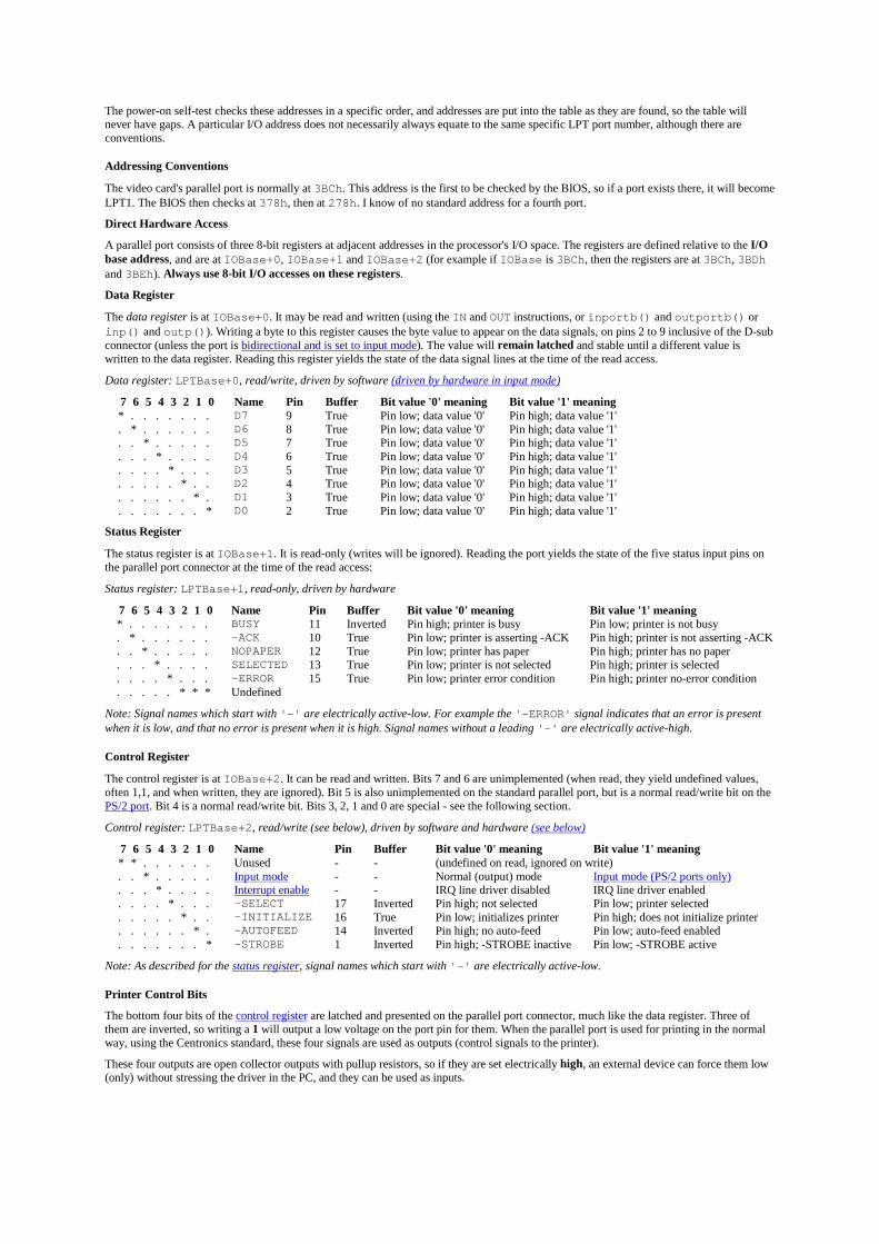
The power-on self-test checks these addresses in a specific order, and addresses are put into the table as they are found, so the table willnever have gaps. A particular I/O address does not necessarily always equate to the same specific LPT port number, although there areconventions.
Addressing Conventions
The video card's parallel port is normally at 3BCh. This address is the first to be checked by the BIOS, so if a port exists there, it will becomeLPT1. The BIOS then checks at 378h, then at 278h. I know of no standard address for a fourth port.
Direct Hardware Access
A parallel port consists of three 8-bit registers at adjacent addresses in the processor's I/O space. The registers are defined relative to the I/Obase address, and are at IOBase+0, IOBase+1 and IOBase+2 (for example if IOBase is 3BCh, then the registers are at 3BCh, 3BDhand 3BEh). Always use 8-bit I/O accesses on these registers.
Data Register
The data register is at IOBase+0. It may be read and written (using the IN and OUT instructions, or inportb() and outportb() orinp() and outp()). Writing a byte to this register causes the byte value to appear on the data signals, on pins 2 to 9 inclusive of the D-subconnector (unless the port is bidirectional and is set to input mode). The value will remain latched and stable until a different value iswritten to the data register. Reading this register yields the state of the data signal lines at the time of the read access.
Data register: LPTBase+0, read/write, driven by software (driven by hardware in input mode)
7 6 5 4 3 2 1 0 Name Pin Buffer Bit value '0' meaning Bit value '1' meaning* . . . . . . . D7 9 True Pin low; data value '0' Pin high; data value '1'. * . . . . . . D6 8 True Pin low; data value '0' Pin high; data value '1'. . * . . . . . D5 7 True Pin low; data value '0' Pin high; data value '1'. . . * . . . . D4 6 True Pin low; data value '0' Pin high; data value '1'. . . . * . . . D3 5 True Pin low; data value '0' Pin high; data value '1'. . . . . * . . D2 4 True Pin low; data value '0' Pin high; data value '1'. . . . . . * . D1 3 True Pin low; data value '0' Pin high; data value '1'. . . . . . . * D0 2 True Pin low; data value '0' Pin high; data value '1'
Status Register
The status register is at IOBase+1. It is read-only (writes will be ignored). Reading the port yields the state of the five status input pins onthe parallel port connector at the time of the read access:
Status register: LPTBase+1, read-only, driven by hardware
7 6 5 4 3 2 1 0 Name Pin Buffer Bit value '0' meaning Bit value '1' meaning* . . . . . . . BUSY 11 Inverted Pin high; printer is busy Pin low; printer is not busy. * . . . . . . -ACK 10 True Pin low; printer is asserting -ACK Pin high; printer is not asserting -ACK. . * . . . . . NOPAPER 12 True Pin low; printer has paper Pin high; printer has no paper. . . * . . . . SELECTED 13 True Pin low; printer is not selected Pin high; printer is selected. . . . * . . . -ERROR 15 True Pin low; printer error condition Pin high; printer no-error condition. . . . . * * * Undefined
Note: Signal names which start with '-' are electrically active-low. For example the '-ERROR' signal indicates that an error is presentwhen it is low, and that no error is present when it is high. Signal names without a leading '-' are electrically active-high.
Control Register
The control register is at IOBase+2. It can be read and written. Bits 7 and 6 are unimplemented (when read, they yield undefined values,often 1,1, and when written, they are ignored). Bit 5 is also unimplemented on the standard parallel port, but is a normal read/write bit on thePS/2 port. Bit 4 is a normal read/write bit. Bits 3, 2, 1 and 0 are special - see the following section.
Control register: LPTBase+2, read/write (see below), driven by software and hardware (see below)
7 6 5 4 3 2 1 0 Name Pin Buffer Bit value '0' meaning Bit value '1' meaning* * . . . . . . Unused - - (undefined on read, ignored on write). . * . . . . . Input mode - - Normal (output) mode Input mode (PS/2 ports only). . . * . . . . Interrupt enable - - IRQ line driver disabled IRQ line driver enabled. . . . * . . . -SELECT 17 Inverted Pin high; not selected Pin low; printer selected. . . . . * . . -INITIALIZE 16 True Pin low; initializes printer Pin high; does not initialize printer. . . . . . * . -AUTOFEED 14 Inverted Pin high; no auto-feed Pin low; auto-feed enabled. . . . . . . * -STROBE 1 Inverted Pin high; -STROBE inactive Pin low; -STROBE active
Note: As described for the status register, signal names which start with '-' are electrically active-low.
Printer Control Bits
The bottom four bits of the control register are latched and presented on the parallel port connector, much like the data register. Three ofthem are inverted, so writing a 1 will output a low voltage on the port pin for them. When the parallel port is used for printing in the normalway, using the Centronics standard, these four signals are used as outputs (control signals to the printer).
These four outputs are open collector outputs with pullup resistors, so if they are set electrically high, an external device can force them low(only) without stressing the driver in the PC, and they can be used as inputs.
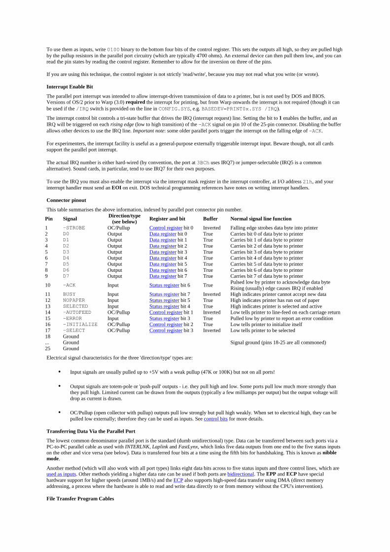
To use them as inputs, write 0100 binary to the bottom four bits of the control register. This sets the outputs all high, so they are pulled highby the pullup resistors in the parallel port circuitry (which are typically 4700 ohms). An external device can then pull them low, and you canread the pin states by reading the control register. Remember to allow for the inversion on three of the pins.
If you are using this technique, the control register is not strictly 'read/write', because you may not read what you write (or wrote).
Interrupt Enable Bit
The parallel port interrupt was intended to allow interrupt-driven transmission of data to a printer, but is not used by DOS and BIOS.Versions of OS/2 prior to Warp (3.0) required the interrupt for printing, but from Warp onwards the interrupt is not required (though it canbe used if the /IRQ switch is provided on the line in CONFIG.SYS, e.g. BASEDEV=PRINT0x.SYS /IRQ).
The interrupt control bit controls a tri-state buffer that drives the IRQ (interrupt request) line. Setting the bit to 1 enables the buffer, and anIRQ will be triggered on each rising edge (low to high transition) of the -ACK signal on pin 10 of the 25-pin connector. Disabling the bufferallows other devices to use the IRQ line. Important note: some older parallel ports trigger the interrupt on the falling edge of -ACK.
For experimenters, the interrupt facility is useful as a general-purpose externally triggerable interrupt input. Beware though, not all cardssupport the parallel port interrupt.
The actual IRQ number is either hard-wired (by convention, the port at 3BCh uses IRQ7) or jumper-selectable (IRQ5 is a commonalternative). Sound cards, in particular, tend to use IRQ7 for their own purposes.
To use the IRQ you must also enable the interrupt via the interrupt mask register in the interrupt controller, at I/O address 21h, and yourinterrupt handler must send an EOI on exit. DOS technical programming references have notes on writing interrupt handlers.
Connector pinout
This table summarises the above information, indexed by parallel port connector pin number.
Pin Signal Direction/type(see below) Register and bit Buffer Normal signal line function
1 -STROBE OC/Pullup Control register bit 0 Inverted Falling edge strobes data byte into printer2 D0 Output Data register bit 0 True Carries bit 0 of data byte to printer3 D1 Output Data register bit 1 True Carries bit 1 of data byte to printer4 D2 Output Data register bit 2 True Carries bit 2 of data byte to printer5 D3 Output Data register bit 3 True Carries bit 3 of data byte to printer6 D4 Output Data register bit 4 True Carries bit 4 of data byte to printer7 D5 Output Data register bit 5 True Carries bit 5 of data byte to printer8 D6 Output Data register bit 6 True Carries bit 6 of data byte to printer9 D7 Output Data register bit 7 True Carries bit 7 of data byte to printer
10 -ACK Input Status register bit 6 True Pulsed low by printer to acknowledge data byteRising (usually) edge causes IRQ if enabled
11 BUSY Input Status register bit 7 Inverted High indicates printer cannot accept new data12 NOPAPER Input Status register bit 5 True High indicates printer has run out of paper13 SELECTED Input Status register bit 4 True High indicates printer is selected and active14 -AUTOFEED OC/Pullup Control register bit 1 Inverted Low tells printer to line-feed on each carriage return15 -ERROR Input Status register bit 3 True Pulled low by printer to report an error condition16 -INITIALIZE OC/Pullup Control register bit 2 True Low tells printer to initialize itself17 -SELECT OC/Pullup Control register bit 3 Inverted Low tells printer to be selected18 Ground... Ground Signal ground (pins 18-25 are all commoned)25 Ground
Electrical signal characteristics for the three 'direction/type' types are:
• Input signals are usually pulled up to +5V with a weak pullup (47K or 100K) but not on all ports!
• Output signals are totem-pole or 'push-pull' outputs - i.e. they pull high and low. Some ports pull low much more strongly thanthey pull high. Limited current can be drawn from the outputs (typically a few milliamps per output) but the output voltage willdrop as current is drawn.
• OC/Pullup (open collector with pullup) outputs pull low strongly but pull high weakly. When set to electrical high, they can bepulled low externally; therefore they can be used as inputs. See control bits for more details.
Transferring Data Via the Parallel Port
The lowest common denominator parallel port is the standard (dumb unidirectional) type. Data can be transferred between such ports via aPC-to-PC parallel cable as used with INTERLNK, Laplink and FastLynx, which links five data outputs from one end to the five status inputson the other and vice versa (see below). Data is transferred four bits at a time using the fifth bits for handshaking. This is known as nibblemode.
Another method (which will also work with all port types) links eight data bits across to five status inputs and three control lines, which areused as inputs. Other methods yielding a higher data rate can be used if both ports are bidirectional. The EPP and ECP have specialhardware support for higher speeds (around 1MB/s) and the ECP also supports high-speed data transfer using DMA (direct memoryaddressing, a process where the hardware is able to read and write data directly to or from memory without the CPU's intervention).
File Transfer Program Cables
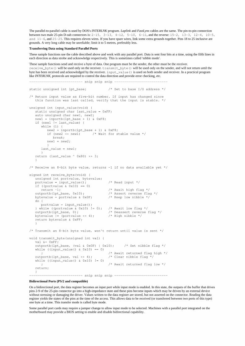
The parallel-to-parallel cable is used by DOS's INTERLNK program. Laplink and FastLynx cables are the same. The pin-to-pin connectionbetween two male 25-pin D-sub connectors is: 2-15, 3-13, 4-12, 5-10, 6-11, and the reverse: 15-2, 13-3, 12-4, 10-5,and 11-6, and 25-25. This requires eleven wires. If you have spare wires, link some extra grounds together. Pins 18 to 25 inclusive aregrounds. A very long cable may be unreliable; limit it to 5 metres, preferably less.
Transferring Data using Standard Parallel Ports
These sample functions use the cable described above and work with any parallel port. Data is sent four bits at a time, using the fifth lines ineach direction as data strobe and acknowledge respectively. This is sometimes called 'nibble mode'.
These sample functions send and receive a byte of data. One program must be the sender, the other must be the receiver.receive_byte() will be used only on the receiver. transmit_byte() will be used only on the sender, and will not return until thebyte has been received and acknowledged by the receiver. input_value() is used on both sender and receiver. In a practical programlike INTERLNK, protocols are required to control the data direction and provide error checking, etc.
--------------------------- snip snip snip ---------------------------
static unsigned int lpt_base; /* Set to base I/O address */
/* Return input value as five-bit number. If input has changed since this function was last called, verify that the input is stable. */
unsigned int input_value(void) { static unsigned char last_value = 0xFF; auto unsigned char new1, new2; new1 = inportb(lpt_base + 1) & 0xF8; if (new1 != last_value) { while (1) { new2 = inportb(lpt_base + 1) & 0xF8; if (new2 == new1) /* Wait for stable value */ break; new1 = new2; } last_value = new1; } return (last_value ^ 0x80) >> 3; }
/* Receive an 8-bit byte value, returns -1 if no data available yet */
signed int receive_byte(void) { unsigned int portvalue, bytevalue; portvalue = input_value(); /* Read input */ if ((portvalue & 0x10) == 0) return -1; /* Await high flag */ outportb(lpt_base, 0x10); /* Assert reverse flag */ bytevalue = portvalue & 0x0F; /* Keep low nibble */ do { portvalue = input_value(); } while ((portvalue & 0x10) != 0); /* Await low flag */ outportb(lpt_base, 0); /* Deassert reverse flag */ bytevalue |= (portvalue << 4); /* High nibble */ return bytevalue & 0xFF; }
/* Transmit an 8-bit byte value, won't return until value is sent */
void transmit_byte(unsigned int val) { val &= 0xFF; outportb(lpt_base, (val & 0x0F) | 0x10); /* Set nibble flag */ while ((input_value() & 0x10) == 0) ; /* Await returned flag high */ outportb(lpt_base, val >> 4); /* Clear nibble flag */ while ((input_value() & 0x10) != 0) ; /* Await returned flag low */ return; }--------------------------- snip snip snip ---------------------------
Bidirectional Ports (PS/2 and compatible)
On a bidirectional port, the data register becomes an input port while input mode is enabled. In this state, the outputs of the buffer that drivespins 2-9 of the 25-pin connector go into a high-impedance state and these pins become inputs which may be driven by an external devicewithout stressing or damaging the driver. Values written to the data register are stored, but not asserted on the connector. Reading the dataregister yields the states of the pins at the time of the access. This allows data to be received (or transferred between two ports of this type)one byte at a time. This transfer mode is called byte mode.
Some parallel port cards may require a jumper change to allow input mode to be selected. Machines with a parallel port integrated on themotherboard may provide a BIOS setting to enable and disable bidirectional capability.
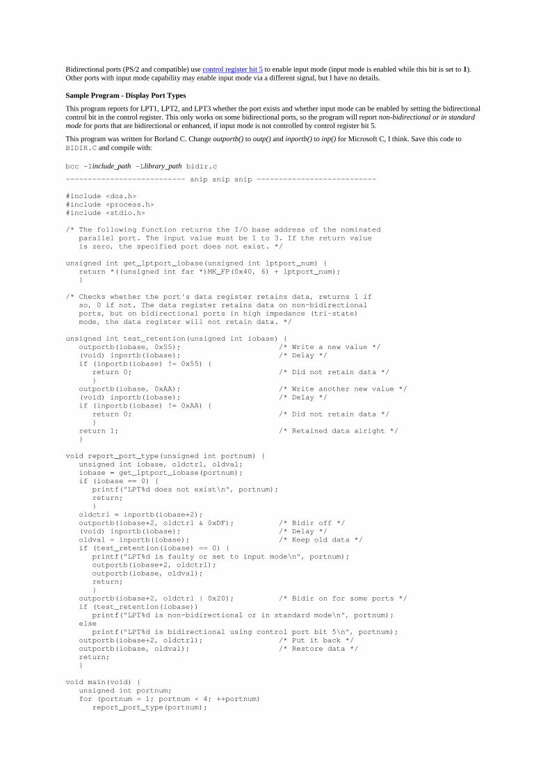
Bidirectional ports (PS/2 and compatible) use control register bit 5 to enable input mode (input mode is enabled while this bit is set to 1).Other ports with input mode capability may enable input mode via a different signal, but I have no details.
Sample Program - Display Port Types
This program reports for LPT1, LPT2, and LPT3 whether the port exists and whether input mode can be enabled by setting the bidirectionalcontrol bit in the control register. This only works on some bidirectional ports, so the program will report non-bidirectional or in standardmode for ports that are bidirectional or enhanced, if input mode is not controlled by control register bit 5.
This program was written for Borland C. Change outportb() to outp() and inportb() to inp() for Microsoft C, I think. Save this code toBIDIR.C and compile with:
bcc -Iinclude_path -Llibrary_path bidir.c
--------------------------- snip snip snip ---------------------------
#include <dos.h>#include <process.h>#include <stdio.h>
/* The following function returns the I/O base address of the nominated parallel port. The input value must be 1 to 3. If the return value is zero, the specified port does not exist. */
unsigned int get_lptport_iobase(unsigned int lptport_num) { return *((unsigned int far *)MK_FP(0x40, 6) + lptport_num); }
/* Checks whether the port's data register retains data, returns 1 if so, 0 if not. The data register retains data on non-bidirectional ports, but on bidirectional ports in high impedance (tri-state) mode, the data register will not retain data. */
unsigned int test_retention(unsigned int iobase) { outportb(iobase, 0x55); /* Write a new value */ (void) inportb(iobase); /* Delay */ if (inportb(iobase) != 0x55) { return 0; /* Did not retain data */ } outportb(iobase, 0xAA); /* Write another new value */ (void) inportb(iobase); /* Delay */ if (inportb(iobase) != 0xAA) { return 0; /* Did not retain data */ } return 1; /* Retained data alright */ }
void report_port_type(unsigned int portnum) { unsigned int iobase, oldctrl, oldval; iobase = get_lptport_iobase(portnum); if (iobase == 0) { printf("LPT%d does not exist\n", portnum); return; } oldctrl = inportb(iobase+2); outportb(iobase+2, oldctrl & 0xDF); /* Bidir off */ (void) inportb(iobase); /* Delay */ oldval = inportb(iobase); /* Keep old data */ if (test_retention(iobase) == 0) { printf("LPT%d is faulty or set to input mode\n", portnum); outportb(iobase+2, oldctrl); outportb(iobase, oldval); return; } outportb(iobase+2, oldctrl | 0x20); /* Bidir on for some ports */ if (test_retention(iobase)) printf("LPT%d is non-bidirectional or in standard mode\n", portnum); else printf("LPT%d is bidirectional using control port bit 5\n", portnum); outportb(iobase+2, oldctrl); /* Put it back */ outportb(iobase, oldval); /* Restore data */ return; }
void main(void) { unsigned int portnum; for (portnum = 1; portnum < 4; ++portnum) report_port_type(portnum);
exit(0); }--------------------------- snip snip snip ---------------------------
Enhanced Ports
The major types of parallel ports are:Name Bidirectional DMA capability
Standard ('SPP') No NoBidirectional (PS/2) Yes NoEPP (Enhanced Parallel Port) Yes (see below) NoECP (Extended Capabilities Port) Yes (see below) Yes
The PS/2 bidirectional port is a standard port with input mode capability, enabled via bit 5 of the control register.
The EPP (Enhanced Parallel Port) and ECP (Extended Capabilities Port) are described in the IEEE 1284 standard of 1994, which gives thephysical, I/O and BIOS interfaces. Both are backward-compatible with the original parallel port, and add special modes which includebidirectional data transfer capability. These modes support fast data transfer between computers and printers, and between computers, andsupport multiple printers or other peripherals on the same port. In their enhanced modes, they re-define the control and status lines of theparallel port connector, using it as a slow multiplexed parallel bus. The ECP supports DMA (direct memory access) for automated high-speed data transfer.
Links
http://www.fapo.com/ Warp 9 Engineering (commercial) home page - technical information on all port types.
http://www.pcgadgets.com/upcatlog.html PC Gadgets (commercial) catalogue - parallel-port unit to drive stepper motors and monitorswitches.
http://www.senet.com.au/~cpeacock/ Craig Peacock's Interfacing the PC page - technical information on all port types, links to relevantmaterial, several PC interfacing projects.
End of Kris Heidenstrom's PC Parallel Port Mini-FAQ
�The Linux 2.4 Parallel Port Subsystem
<<< Previous Next >>>
The printer driver
The printer driver, lp is a character special device driver and a parport client. As a character special device driver it registers a structfile_operations using register_chrdev, with pointers filled in for write, ioctl, open and release. As a client of parport, itregisters a struct parport_driver using parport_register_driver, so that parport knows to call lp_attach when a new parallelport is discovered (and lp_detach when it goes away).
The parallel port console functionality is also implemented in drivers/char/lp.c, but that won't be covered here (it's quite simplethough).
The initialisation of the driver is quite easy to understand (see lp_init). The lp_table is an array of structures that contain informationabout a specific device (the struct pardevice associated with it, for example). That array is initialised to sensible values first of all.
Next, the printer driver calls register_chrdev passing it a pointer to lp_fops, which contains function pointers for the printer driver'simplementation of open, write, and so on. This part is the same as for any character special device driver.
After successfully registering itself as a character special device driver, the printer driver registers itself as a parport client usingparport_register_driver. It passes a pointer to this structure:
static struct parport_driver lp_driver = { "lp", lp_attach, lp_detach, NULL};
The lp_detach function is not very interesting (it does nothing); the interesting bit is lp_attach. What goes on here depends onwhether the user supplied any parameters. The possibilities are: no parameters supplied, in which case the printer driver uses every port thatis detected; the user supplied the parameter "auto", in which case only ports on which the device ID string indicates a printer is present areused; or the user supplied a list of parallel port numbers to try, in which case only those are used.
For each port that the printer driver wants to use (see lp_register), it calls parport_register_device and stores the resultingstruct pardevice pointer in the lp_table. If the user told it to do so, it then resets the printer.
The other interesting piece of the printer driver, from the point of view of parport, is lp_write. In this function, the user space processhas data that it wants printed, and the printer driver hands it off to the parport code to deal with.

The parport functions it uses that we have not seen yet are parport_negotiate, parport_set_timeout, andparport_write. These functions are part of the IEEE 1284 implementation.
The way the IEEE 1284 protocol works is that the host tells the peripheral what transfer mode it would like to use, and the peripheral eitheraccepts that mode or rejects it; if the mode is rejected, the host can try again with a different mode. This is the negotation phase. Once theperipheral has accepted a particular transfer mode, data transfer can begin that mode.
The particular transfer mode that the printer driver wants to use is named in IEEE 1284 as "compatibility" mode, and the function to requesta particular mode is called parport_negotiate.
#include <parport.h>
int parport_negotiate(struct parport *port, int mode);
The modes parameter is a symbolic constant representing an IEEE 1284 mode; in this instance, it is IEEE1284_MODE_COMPAT.(Compatibility mode is slightly different to the other modes---rather than being specifically requested, it is the default until another mode isselected.)
Back to lp_write then. First, access to the parallel port is secured with parport_claim_or_block. At this point the driver mightsleep, waiting for another driver (perhaps a Zip drive driver, for instance) to let the port go. Next, it goes to compatibility mode usingparport_negotiate.
The main work is done in the write-loop. In particular, the line that hands the data over to parport reads:
written = parport_write (port, kbuf, copy_size);
The parport_write function writes data to the peripheral using the currently selected transfer mode (compatibility mode, in this case). Itreturns the number of bytes successfully written:
#include <parport.h>
ssize_t parport_write(struct parport *port, const void *buf, size_t len);
ssize_t parport_read(struct parport *port, void *buf, size_t len);
(parport_read does what it sounds like, but only works for modes in which reverse transfer is possible. Of course, parport_writeonly works in modes in which forward transfer is possible, too.)
The buf pointer should be to kernel space memory, and obviously the len parameter specifies the amount of data to transfer.
In fact what parport_write does is call the appropriate block transfer function from the struct parport_operations:
struct parport_operations { [...]
/* Block read/write */ size_t (*epp_write_data) (struct parport *port, const void *buf, size_t len, int flags); size_t (*epp_read_data) (struct parport *port, void *buf, size_t len, int flags); size_t (*epp_write_addr) (struct parport *port, const void *buf, size_t len, int flags); size_t (*epp_read_addr) (struct parport *port, void *buf, size_t len, int flags);
size_t (*ecp_write_data) (struct parport *port, const void *buf, size_t len, int flags); size_t (*ecp_read_data) (struct parport *port, void *buf, size_t len, int flags); size_t (*ecp_write_addr) (struct parport *port, const void *buf, size_t len, int flags);
size_t (*compat_write_data) (struct parport *port, const void *buf, size_t len, int flags); size_t (*nibble_read_data) (struct parport *port, void *buf, size_t len, int flags);

size_t (*byte_read_data) (struct parport *port, void *buf, size_t len, int flags);};
The transfer code in parport will tolerate a data transfer stall only for so long, and this timeout can be specified withparport_set_timeout, which returns the previous timeout:
#include <parport.h>
long parport_set_timeout(struct pardevice *dev, long inactivity);
This timeout is specific to the device, and is restored on parport_claim.
The next function to look at is the one that allows processes to read from /dev/lp0: lp_read. It's short, like lp_write.
The semantics of reading from a line printer device are as follows:
• Switch to reverse nibble mode.
• Try to read data from the peripheral using reverse nibble mode, until either the user-provided buffer is full or the peripheralindicates that there is no more data.
• If there was data, stop, and return it.
• Otherwise, we tried to read data and there was none. If the user opened the device node with the O_NONBLOCK flag, return.Otherwise wait until an interrupt occurs on the port (or a timeout elapses).
<<< Previous Home Next >>>Port drivers User-level device drivers
#ifdef SCCSIDstatic sccsid[] = "@(#) lp.c 1.1 91/03/18 19:50:09";#endif/****************************************************************************** Hardware line printer driver.
This module implements the functionality needed to drive a PC-styleparallel port. All function calls are non-blocking. The functionpassed to lpt_io() determine what action is taken. The actionsare defined in lp.h and again for reference below. In general, touse a port, the following procedure is used:
Test for port presence (lpt_io(IS_PRESENT))if so, then (lpt_io(INIT) to initialize the port
For each character, test lpt_io(IS_BUSY)When port is not busy, lpt_io(OUT) with the character
Optionally, one may retrieve the status of the printer port withlpt_io(STAT).
Finally, if one desires to select or deselect a printer (assert ordeassert the SELECT line on the interface), call lpt_io(SELECT) withthe appropriate argument.
Two test routines are provided in this module. Defining TEST_1includes a main() and creates a program that outputs 50,000 "*"characters to the port and displays transmission statistics.
Defining TEST_2 creates a program that will output a file specifiedon the command line or redirected into it.
Following is a table of function calls vs arguments vs returned value:
Function Port Byte Mode Returned value------------------------------------------------------------------------------IN LPT base port N/A IN
Byte Read
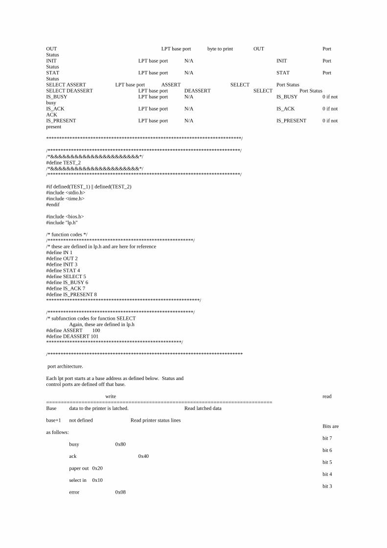
OUT LPT base port byte to print OUT PortStatusINIT LPT base port N/A INIT PortStatusSTAT LPT base port N/A STAT PortStatusSELECT ASSERT LPT base port ASSERT SELECT Port StatusSELECT DEASSERT LPT base port DEASSERT SELECT Port StatusIS_BUSY LPT base port N/A IS_BUSY 0 if notbusyIS_ACK LPT base port N/A IS_ACK 0 if notACKIS_PRESENT LPT base port N/A IS_PRESENT 0 if notpresent
***************************************************************************/
/**************************************************************************//*&&&&&&&&&&&&&&&&&&&&&&*/#define TEST_2/*&&&&&&&&&&&&&&&&&&&&&&*//**************************************************************************/
#if defined(TEST_1) || defined(TEST_2)#include <stdio.h>#include <time.h>#endif
#include <bios.h>#include "lp.h"
/* function codes *//********************************************************//* these are defined in lp.h and are here for reference#define IN 1#define OUT 2#define INIT 3#define STAT 4#define SELECT 5#define IS_BUSY 6#define IS_ACK 7#define IS_PRESENT 8***********************************************************/
/********************************************************//* subfunction codes for function SELECT
Again, these are defined in lp.h#define ASSERT 100#define DEASSERT 101****************************************************/
/***************************************************************************
port architecture.
Each lpt port starts at a base address as defined below. Status andcontrol ports are defined off that base.
write read=============================================================================Base data to the printer is latched. Read latched data
base+1 not defined Read printer status linesBits are
as follows:bit 7
busy 0x80bit 6
ack 0x40bit 5
paper out 0x20bit 4
select in 0x10bit 3
error 0x08

2,1,0Not used
base+2 write control bits read the same control bitsBits are defined as follows: Normally reads the latchedbit 0 *strobe 0x01 bits written to same portbit 1 *auto feed 0x02bit 2 init printer 0x04bit 3 *select out 0x08bit 4 turn on irq7 on ACK hi-2-lo toggle 0x105,6,7 not used
******************************************************************************//********************************************//* defined in lp.h and are here for ref only#define LPT1 0x3bc#define LPT2 0x378#define LPT3 0x278**********************************************/
#ifdef TEST_1main(){
unsigned status;unsigned lpt_io();unsigned int i;time_t start_time, end_time;
status = lpt_io(LPT1, 0, INIT);printf("sending 50,000 chars\n");start_time = time(NULL);
for (i=0;i<50000;i++) {while ( status=lpt_io(LPT1,0,IS_BUSY) ) /* spin while busy */
;status = lpt_io(LPT1, '*', OUT);if (!(i%1000))
printf("*");}end_time = time(NULL);printf("\n50,000 chars in %ld seconds or %ld chars/sec\n",
end_time-start_time,50000L / (end_time-start_time) );
exit(0);
}
#endif
#ifdef TEST_2/* this version outputs a file to lpt1 */main(argc, argv)int argc;char **argv;{
unsigned status;unsigned lpt_io();long int i=0L;time_t start_time, end_time;int character;int busy_flag=0;
status = lpt_io(LPT1, 0, INIT);start_time = time(NULL);
if (argc > 1) {if (freopen(argv[1], "rb", stdin) == (FILE *) NULL) {
cprintf("Error, file %s open failed\n", argv[1]);exit(1);
}}
while ( (character = fgetchar()) != EOF) {
while ( status=lpt_io(LPT1,0,IS_BUSY) ){ /* spin while busy */
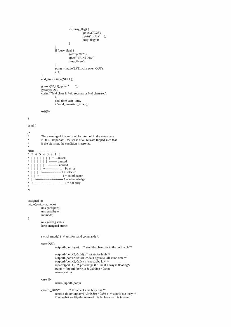
if (!busy_flag) {gotoxy(70,25);cputs("BUSY ");busy_flag=1;
}}if (busy_flag) {
gotoxy(70,25);cputs("PRINTING");busy_flag=0;
}status = lpt_io(LPT1, character, OUT);i++;
}end_time = time(NULL);
gotoxy(70,25);cputs(" ");gotoxy(1,24);cprintf("%ld chars in %ld seconds or %ld chars/sec",
i,end_time-start_time,i / (end_time-start_time) );
exit(0);
}
#endif
/** The meaning of life and the bits returned in the status byte* NOTE: Important - the sense of all bits are flipped such that* if the bit is set, the condition is asserted.**Bits----------------------------* 7 6 5 4 3 2 1 0* | | | | | | | +-- unused* | | | | | | +------ unused* | | | | | +---------- unused* | | | | +-------------- 1 = i/o error* | | | +------------------ 1 = selected* | | +---------------------- 1 = out of paper* | +-------------------------- 1 = acknowledge* +------------------------------ 1 = not busy**/
unsigned intlpt_io(port,byte,mode)
unsigned port;unsigned byte;int mode;
{unsigned i,j,status;long unsigned otime;
switch (mode) { /* test for valid commands */
case OUT:outportb(port,byte); /* send the character to the port latch */
outportb(port+2, 0x0d); /* set strobe high */outportb(port+2, 0x0d); /* do it again to kill some time */outportb(port+2, 0x0c); /* set strobe low */inportb(port+1); /* pre-charge the line if +busy is floating*/status = (inportb(port+1) & 0x00f8) ^ 0x48;return(status);
case IN:return(inportb(port));
case IS_BUSY: /* this checks the busy line */return ( (inportb(port+1) & 0x80) ^ 0x80 ); /* zero if not busy *//* note that we flip the sense of this bit because it is inverted
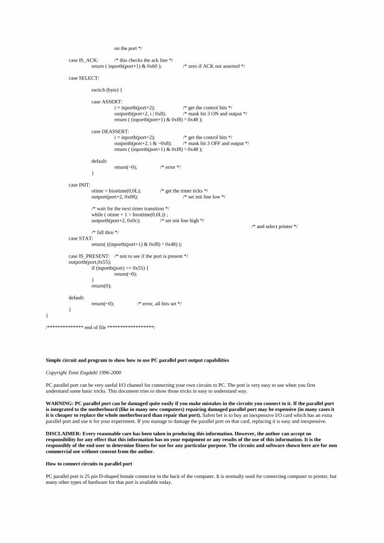
on the port */
case IS_ACK: /* this checks the ack line */return ( inportb(port+1) & 0x60 ); /* zero if ACK not asserted */
case SELECT:
switch (byte) {
case ASSERT:i = inportb(port+2); /* get the control bits */outportb(port+2, i | 0x8); /* mask bit 3 ON and output */return ( (inportb(port+1) & 0xf8) ^ 0x48 );
case DEASSERT:i = inportb(port+2); /* get the control bits */outportb(port+2, i & ~0x8); /* mask bit 3 OFF and output */return ( (inportb(port+1) & 0xf8) ^ 0x48 );
default:return(~0); /* error */
}
case INIT:otime = biostime(0,0L); /* get the timer ticks */outport(port+2, 0x08); /* set init line low */
/* wait for the next timer transition */while ( otime + 1 > biostime(0,0L)) ;outportb(port+2, 0x0c); /* set init line high */
/* and select printer *//* fall thru */
case STAT:return( ((inportb(port+1) & 0xf8) ^ 0x48) );
case IS_PRESENT: /* test to see if the port is present */outportb(port,0x55);
if (inportb(port) == 0x55) {return(~0);
}return(0);
default:return(~0); /* error, all bits set */
}}
/************** end of file ******************/
Simple circuit and program to show how to use PC parallel port output capabilities
Copyright Tomi Engdahl 1996-2000
PC parallel port can be very useful I/O channel for connecting your own circuits to PC. The port is very easy to use when you firstunderstand some basic tricks. This document tries to show those tricks in easy to understand way.
WARNING: PC parallel port can be damaged quite easily if you make mistakes in the circuits you connect to it. If the parallel portis integrated to the motherboard (like in many new computers) repairing damaged parallel port may be expensive (in many cases itit is cheaper to replace the whole motherborard than repair that port). Safest bet is to buy an inexpensive I/O card which has an extraparallel port and use it for your experiment. If you manage to damage the parallel port on that card, replacing it is easy and inexpensive.
DISCLAIMER: Every reasonable care has been taken in producing this information. However, the author can accept noresponsibility for any effect that this information has on your equipment or any results of the use of this information. It is theresponsibly of the end user to determine fitness for use for any particular purpose. The circuits and software shown here are for noncommercial use without consent from the author.
How to connect circuits to parallel port
PC parallel port is 25 pin D-shaped female connector in the back of the computer. It is normally used for connecting computer to printer, butmany other types of hardware for that port is available today.
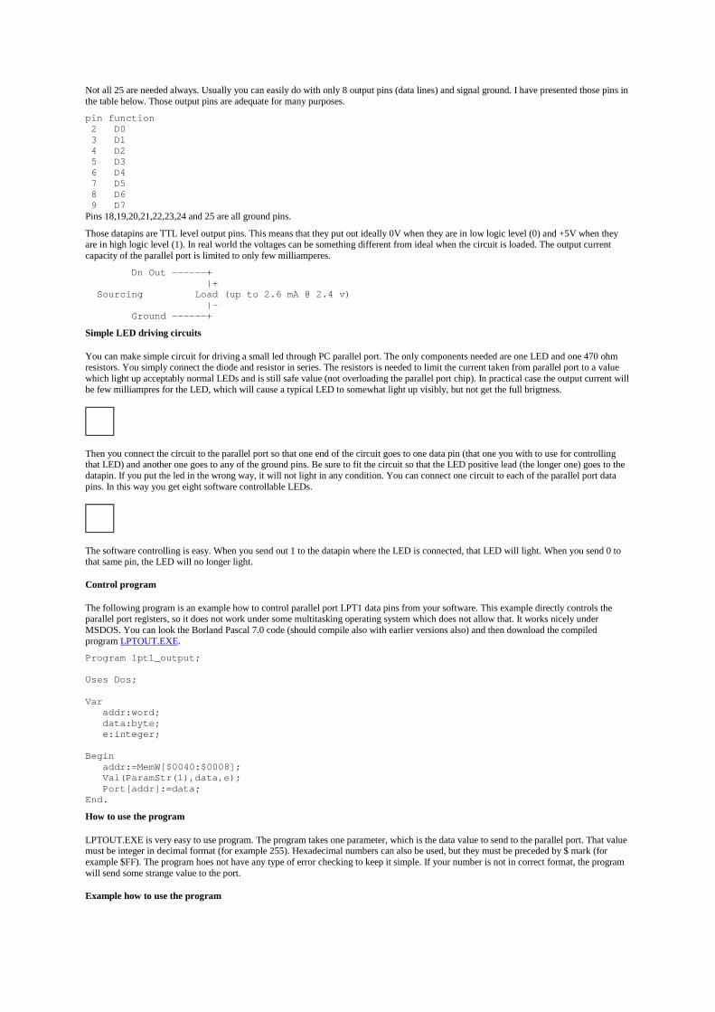
Not all 25 are needed always. Usually you can easily do with only 8 output pins (data lines) and signal ground. I have presented those pins inthe table below. Those output pins are adequate for many purposes.
pin function 2 D0 3 D1 4 D2 5 D3 6 D4 7 D5 8 D6 9 D7Pins 18,19,20,21,22,23,24 and 25 are all ground pins.
Those datapins are TTL level output pins. This means that they put out ideally 0V when they are in low logic level (0) and +5V when theyare in high logic level (1). In real world the voltages can be something different from ideal when the circuit is loaded. The output currentcapacity of the parallel port is limited to only few milliamperes.
Dn Out ------+ |+ Sourcing Load (up to 2.6 mA @ 2.4 v) |- Ground ------+
Simple LED driving circuits
You can make simple circuit for driving a small led through PC parallel port. The only components needed are one LED and one 470 ohmresistors. You simply connect the diode and resistor in series. The resistors is needed to limit the current taken from parallel port to a valuewhich light up acceptably normal LEDs and is still safe value (not overloading the parallel port chip). In practical case the output current willbe few milliampres for the LED, which will cause a typical LED to somewhat light up visibly, but not get the full brigtness.
Then you connect the circuit to the parallel port so that one end of the circuit goes to one data pin (that one you with to use for controllingthat LED) and another one goes to any of the ground pins. Be sure to fit the circuit so that the LED positive lead (the longer one) goes to thedatapin. If you put the led in the wrong way, it will not light in any condition. You can connect one circuit to each of the parallel port datapins. In this way you get eight software controllable LEDs.
The software controlling is easy. When you send out 1 to the datapin where the LED is connected, that LED will light. When you send 0 tothat same pin, the LED will no longer light.
Control program
The following program is an example how to control parallel port LPT1 data pins from your software. This example directly controls theparallel port registers, so it does not work under some multitasking operating system which does not allow that. It works nicely underMSDOS. You can look the Borland Pascal 7.0 code (should compile also with earlier versions also) and then download the compiledprogram LPTOUT.EXE.
Program lpt1_output;
Uses Dos;
Var addr:word; data:byte; e:integer;
Begin addr:=MemW[$0040:$0008]; Val(ParamStr(1),data,e); Port[addr]:=data;End.
How to use the program
LPTOUT.EXE is very easy to use program. The program takes one parameter, which is the data value to send to the parallel port. That valuemust be integer in decimal format (for example 255). Hexadecimal numbers can also be used, but they must be preceded by $ mark (forexample $FF). The program hoes not have any type of error checking to keep it simple. If your number is not in correct format, the programwill send some strange value to the port.
Example how to use the program
LPTOUT 0Set all datapins to low level.
LPTOUT 255Set all datapins to high level.
LPTOUT 1Set datapin D0 to high level and all other datapins to low level.
How to calculate your own values to send to program
You have to think the value you give to the program as a binary number. Every bit of the binary number control one output bit. Thefollowing table describes the relation of the bits, parallel port output pins and the value of those bits.
Pin 2 3 4 5 6 7 8 9Bit D0 D1 D2 D3 D4 D5 D6 D7Value 1 2 4 8 16 32 64 128For example if you want to set pins 2 and 3 to logic 1 (led on) then you have to output value 1+2=3. If you want to set on pins 3,5 and 6 thenyou need to output value 2+8+16=26. In this way you can calculate the value for any bit combination you want to output.
Making changes to source code
You can easily change te parallel port number int the source code by just changing the memory address where the program read the parallelport address. For more information, check the following table.
Format of BIOS Data Segment at segment 40h:Offset Size Description 08h WORD Base I/O address of 1st parallel I/O port, zero if none 0Ah WORD Base I/O address of 2nd parallel I/O port, zero if none 0Ch WORD Base I/O address of 3rd parallel I/O port, zero if none 0Eh WORD [non-PS] Base I/O address of 4th parallel I/O port, zero if noneFor example change the line addr:=MemW[$0040:$0008]; in the source code to addr:=MemW[$0040:$000A]; if you want to output toLPT2.
Using other languages
The following examples are short code examples how to write to I/O ports using different languages. In the examples I have used I/O address378h which is one of the addresses where parallel port can be. The following examples are useful in DOS.
Assembler
MOV DX,0378HMOV AL,nOUT DX,ALWhere n is the data you want to output.
BASIC
OUT &H378, NWhere N is the number you want to output.
C
outp(0x378,n);oroutportb(0x378,n);Where N is the data you want to output. The actual I/O port controlling command varies from compiler to compiler because it is not part ofstandardized C libraries.
Here is an example source code for Borland C++ 3.1 compiler:
#include <stdio.h>#include <dos.h>#include <conio.h>
/********************************************//*This program set the parallel port outputs*//********************************************/
void main (void){clrscr(); /* clear screen */outportb(0x378,0xff); /* output the data to parallel port */getch(); /* wait for keypress before exiting */}
Parallel port controlling in windows programs

Direct parallel port controlling in possible under Windows 3.x and Windows 95 directly from 16 bit application programs and DLL libraries.So you can use the C example above in Windows 3.x and Windows 95 if you make your program 16 bit application. If you want to controlparallel port from Visual Basic or Delphi then take a look at the libraries at Parallel Port Central at http://www.lvr.com/parport.htm.
Direct port controlling from application is not possible under Windows NT and to be ale to control the parallel port directly you will need towrite some kind of device driver to do this. You can find also this kind of drivers from Parallel Port Central.
Parallel port controlling in Linux
Linux will allow acess to any port using the ioperm syscall. Here is some code parts for Linux to write 255 to printer port:
#include <stdio.h>#include <stdlib.h>#include <unistd.h>#include <asm/io.h>
#define base 0x378 /* printer port base address */#define value 255 /* numeric value to send to printer port */
main(int argc, char **argv){ if (ioperm(base,1,1)) fprintf(stderr, "Couldn't get the port at %x\n", base), exit(1);
outb(value, base);}Save the source code to file lpt_test.c and compile it with command:gcc -O lpt_test.c -o lpt_test
The user has to have the previledges to have access to the ports for the program to run, so you have to be root to be able to ron this kind ofprograms without access problems. If you want to make a program which can be run by anybody then you have to first set the owner of theprogram to be root (for example do compilation when yhou are root), give the users rights to execute the program and then set the program tobe always executed with owner (root) rights instead of the right of the user who runs it. You can set the programn to be run on owner rightsby using following command:
chmod +s lpt_test
If you want a more useful program, then download my lptout.c parallel port controlling program source code. That program works so thatyou can give the data to send to parallel port as the command line argument (both decimal and hexadecimal numbers supported) to thatprogram and it will then output that value to parallel port. You can compile the source code to lptout command using the following line to dothe compilation:
gcc -O lptout.c -o lptout
After you have compiled the program you can run it easily. For example running ./lptout 0xFF will turn all data pins to 1 and running./lptout 0x00 will turn all data pins to 0.
Controlling some real life electronics
The idea of the interface shown above can be expanded to control some external electronics by simply adding a buffer circuit to the parallelport. The programming can be done in exactly the same way as told in my examples.
Building your own relay controlling circuit
The following circuit is the simples interface you can use to control relay from parallel port:
Vcc | +------+ | __|__ Relay /^\ Diode 1N4002 Coil /---\ | | +------+ | | / 4.7K B |/ Cparallel port >-\/\/\/\/---| NPN Transistor: BC547A or 2N2222Adata pi |\ E | V |parallel port >--------------+ground pin | GroundThe circuit can handle relays which take currents up to 100 mA and operate at 24V or less. The circuit need external power supply which hasthe output voltage which is right for controlling the relay (5..24V depending on relay). The transistor does the switching of current and thediode prevent spikes from the relay coil form damaging your computer (if you leave the diode out, then the transistor and your computer canbe damaged).
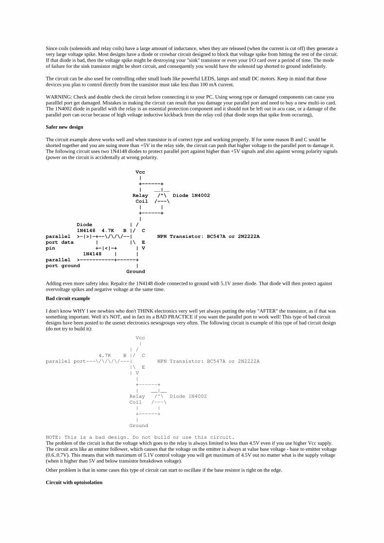
Since coils (solenoids and relay coils) have a large amount of inductance, when they are released (when the current is cut off) they generate avery large voltage spike. Most designs have a diode or crowbar circuit designed to block that voltage spike from hitting the rest of the circuit.If that diode is bad, then the voltage spike might be destroying your "sink" transistor or even your I/O card over a period of time. The modeof failure for the sink transistor might be short circuit, and consequently you would have the solenoid tap shorted to ground indefinitely.
The circuit can be also used for controlling other small loads like powerful LEDS, lamps and small DC motors. Keep in mind that thosedevices you plan to control directly from the transistor must take less than 100 mA current.
WARNING: Check and double check the circuit before connecting it to your PC. Using wrong type or damaged components can cause youparalllel port get damaged. Mistakes in making the circuit can result that you damage your parallel port and need to buy a new multi-io card.The 1N4002 diode in parallel with the relay is an essential protection component and it should not be left out in acu case, or a damage of theparallel port can occur because of high voltage inductive kickback from the relay coil (that diode stops that spike from occuring),
Safer new design
The circuit example above works well and when transistor is of correct type and working properly. If for some reason B and C sould beshorted together and you are suing more than +5V in the relay side, the circuit can push that higher voltage to the parallel port to damage it.The following circuit uses two 1N4148 diodes to protect parallel port against higher than +5V signals and also against wrong polarity signals(power on the circuit is accidentally at wrong polarity.
Vcc | +------+ | __|__ Relay /^\ Diode 1N4002 Coil /---\ | | +------+ | Diode | / 1N4148 4.7K B |/ Cparallel >-|>|-+--\/\/\/--| NPN Transistor: BC547A or 2N2222Aport data | |\ Epin +-|<|-+ | V 1N4148 | |parallel >-----------+------+port ground | Ground
Adding even more safety idea: Repalce the 1N4148 diode connected to ground with 5.1V zener diode. That diode will then protect againstovervoltage spikes and negative voltage at the same time.
Bad circuit example
I don't know WHY I see newbies who don't THINK electronics very well yet always putting the relay "AFTER" the transistor, as if that wassomething important. Well it's NOT, and in fact its a BAD PRACTICE if you want the parallel port to work well! This type of bad circuitdesigns have been posted to the usenet electronics newsgroups very often. The following circuit is example of this type of bad circuit design(do not try to build it):
Vcc | | / 4.7K B |/ Cparallel port---\/\/\/\/---| NPN Transistor: BC547A or 2N2222A |\ E | V | +------+ | __|__ Relay /^\ Diode 1N4002 Coil /---\ | | +------+ | Ground
NOTE: This is a bad design. Do not build or use this circuit.The problem of the circuit is that the voltage which goes to the relay is always limited to less than 4.5V even if you use higher Vcc supply.The circuit acts like an emitter follower, which causes that the voltage on the emitter is always at value base voltage - base to emitter voltage(0.6..0.7V). This means that with maximum of 5.1V control voltage you will get maximum of 4.5V out no matter what is the supply voltage(when it higher than 5V and below transistor breakdown voltage).
Other problem is that in some cases this type of circuit can start to oscillate if the base resistor is right on the edge.
Circuit with optoisolation
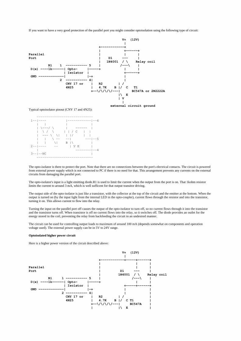
If you want to have a very good protection of the parallel port you might consider optoisolation using the following type of circuit:
V+ (12V) | +------------+ | +------+Parallel | | |Port | D1 --- | | 1N4001 / \ Relay coil R1 1 ----------- 5 | /---\ | D(x) ----1k------| Opto- |-----+ | | | Isolator | +------+ GND -------------| |-+ | 2 ----------- 4| | CNY 17 or | R2 | / 4N25 | 4.7K B |/ C T1 +--\/\/\/\/---| BC547A or 2N2222A |\ E | V | external circuit groundTypical optoisolator pinout (CNY 17 and 4N25):
----------------------------- 1--|---- |------------|--6 | | | | | \---/ \ | ------ | | \ / \ | | / C | | | --- \ \| | |/ | | | | \ -- --| ---|--5 | | \| B |\ | 2--|---- -- | V E | | --------|--4 3--|--NC | -----------------------------
The opto-isolator is there to protect the port. Note that there are no connections between the port's electrical contacts. The circuit is poweredfrom external power supply which is not connected to PC if there is no need for that. This arrangement prevents any currents on the externalcircuits from damaging the parallel port.
The opto-isolator's input is a light emitting diode.R1 is used to limit the current when the output from the port is on. That 1kohm resistorlimits the current to around 3 mA, which is well sufficent for that output transitor driving.
The output side of the opto-isolator is just like a transistor, with the collector at the top of the circuit and the emitter at the bottom. When theoutput is turned on (by the input light from the internal LED in the opto-coupler), current flows through the resistor and into the transistor,turning it on. This allows current to flow into the relay.
Turning the input on the parallel port off causes the output of the opto-isolator to turn off, so no current flows through it into the transistorand the transistor turns off. When transistor is off no current flows into the relay, so it switches off. The diode provides an outlet for theenergy stored in the coil, preventing the relay from backfeeding the circuit in an undesired manner.
The circuit can be used for controlling output loads to maximum of around 100 mA (depends somewhat on components and operationvoltage used). The external power supply can be in 5V to 24V range.
Optoisolated higher power circuit
Here is a higher power version of the circuit described above:
V+ (12V) | +------------+-----+------+ | | |Parallel | | |Port | D1 --- | | 1N4001 / \ Relay coil R1 1 ----------- 5 | /---\ | D(x) ----1k------| Opto- |-----+ | | | Isolator | +-----+------+ GND -------------| |-+ | | 2 ----------- 4| | | CNY 17 or | R2 | / | 4N25 | 4.7K B |/ C T1 | +--\/\/\/\/---| BC547A | | |\ E |

| | V | / / | B |/C T2 \ R3 +----------| power / 10 kohm |\E transistor \ | v | | +----------------------------+ | external circuit groundIn this circuit Q1 is used for controlling the base current of Q2 which controls the actual current. You can select almost any general purposepower transistor for this circuit which matches your current and voltage controlling needs. Some example alternatives are for exampleTIP41C (6A 100V) or 2N3055 (100V 15A). Depending your amplification facter inherint to the transitor Q2 you might not hough be able touse the full current capability of the output device T2 before there will be excessive losses (heating) in that transistor.
This circuit is basically very simple modification of the original optoisolator circuit with one transistor. The difference in this circuit is thathere T2 controls the load current and Q1 acts as a current amplifier for T2 base control current. Optoisolator, R1, R2, Q1, D1 work exactly inthe same way as in one transistor circuit described eariler in this documents. R3 acts like an extra resistor which guarantees that T2 does notconduct when there is no signal fed to the optoisolator (small possible current leaking on optosiolator output does not make T1 and T2 toconduct).
Reading the input pins in parallel port
PC parallel port has 5 input pins. The input pins can be read from the I/O address LPT port base address + 1.
The meaning of the buts in byte you read from that I/O port:
• D0: state not specified
• D1: state not specified
• D2: state not specified
• D3: state of pin 15 (ERROR) inverted
• D4: state of pin 13 (SELECTED)
• D5: state of pin 12 (PAPER OUT)
• D6: state of pin 10 (ACK)
• D7: state of pin 11 (BUSY) inverted
Here are some code snipplets to read LPT port:
Assembler
MOV DX,0379HIN AL,DXYou get the result fo read from AL register
BASIC
N = INP(&H379);Where N is the numerical value you read.
C
in = inportb(0x379);orin = inp(0x379);Where N is the data you want to output. The actual I/O port controlling command varies from compiler to compiler because it is not part ofstandardized C libraries.
Other documents worth to check
• DAGE Scientific . . . using the Parallel Port
• IBM Parallel Port FAQ/Tutorial
• PC parallel port links
• Use of a PC Printer Port for Control and Data Acquisition - described also data input
Tomi Engdahl <[email protected]>
Parallel Port Device Bus
This device started out as a personal interest in building a device to turn lights on and off. It eventually developed into quite a big project,and was expanded to allow different types of devices to be plugged into a common bus. The actions of the bus are controlled through abidirectional parallel port, which allows 8 bits of data output or input, 5 status lines, and 4 control lines. The parallel port control lines areused to drive an Intel i8255 Parallel Peripheral Interface, which is really just a really nice multiplexer. It allows me to interface 24 bus linesto the limited number of lines on the parallel port. See the schematics for the hardware schematics, wiring details, and protocol specs.
I have also written a device driver to drive the bus so that the logic required to place signals on the bus and read data from the bus would betransparent to the user. This device driver is written for Linux and can be compiled in statically or as a loadable kernel module. Feel free tolook through the source if you're interested. It's pretty well commented, even if it's not the most complete.
Finally, since this project evolved into the final project for my Microcomputer Architecture Lab, I wrote a paper on my experiences withbuilding this. I found that it really was quite involved, and so the paper is very long. I don't blame you if you don't read the whole thing, butif you're interested please do!
This guys are also working on a parallel port interface!
Sebastian Kuzminsky and I are jointly working on the third revision bus, in which we hope to remove the bus control logic (the PPI), andwork with only the parallel port lines. There will be 4 addressable devices, each able to process write requests, read requests, and interruptthe CPU for data input. A Linux device driver is soon on the way, as well as schematics and bus specification data, too!
If you're curious about design considerations or generally in the project, feel free to send me mail at [email protected]. I am interestedin hearing your comments!
Standard transfer modes
The "standard" transfer modes in use over the parallel port are "defined" by a document called IEEE 1284. It really just codifies existingpractice and documents protocols (and variations on protocols) that have been in common use for quite some time.
The original definitions of which pin did what were set out by Centronics Data Computer Corporation, but only the printer-side interfacesignals were specified.
By the early 1980s, IBM's host-side implementation had become the most widely used. New printers emerged that claimed Centronicscompatibility, but although compatible with Centronics they differed from one another in a number of ways.
As a result of this, when IEEE 1284 was published in 1994, all that it could really do was document the various protocols that are used forprinters (there are about six variations on a theme).
In addition to the protocol used to talk to Centronics-compatible printers, IEEE 1284 defined other protocols that are used for unidirectionalperipheral-to-host transfers (reverse nibble and reverse byte) and for fast bidirectional transfers (ECP and EPP).
link to the Technology Interfacethe Electronic Journal for Engineering Technology
the Technology Interface /Fall 96
Use of a PC Printer Port for Control and Data Acquisition
by
Peter H. [email protected]
Department of Electrical EngineeringMorgan State University
Abstract: A PC printer port is an inexpensive and yet powerful platform for implementing projects dealing with the control of real worldperipherals. The printer port provides eight TTL outputs, five inputs and four bidirectional leads and it provides a very simple means to usethe PC interrupt structure.
This article discusses how to use program the printer port. A larger manual which deals with such topics as driver circuits, optoisolators,control of DC and stepping motors, infrared and radio remote control, digital and analog multiplexing, D/A and A/D is avaialable. See
http://www.access.digex.net/~pha
A special thanks to Morgan State University students Towanda Malone, Christine Samuels and H. Paul Roach for their technicalcontributions and to New Mexico State University student Kyle Quinnell for preparing the html file.
I. Printer Port Basics
A. Port Assignments
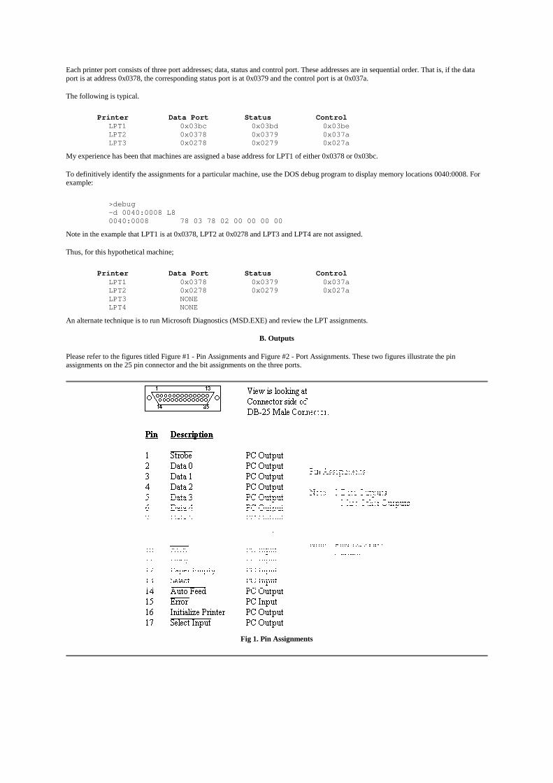
Each printer port consists of three port addresses; data, status and control port. These addresses are in sequential order. That is, if the dataport is at address 0x0378, the corresponding status port is at 0x0379 and the control port is at 0x037a.
The following is typical.
Printer Data Port Status ControlLPT1 0x03bc 0x03bd 0x03beLPT2 0x0378 0x0379 0x037aLPT3 0x0278 0x0279 0x027a
My experience has been that machines are assigned a base address for LPT1 of either 0x0378 or 0x03bc.
To definitively identify the assignments for a particular machine, use the DOS debug program to display memory locations 0040:0008. Forexample:
>debug-d 0040:0008 L80040:0008 78 03 78 02 00 00 00 00
Note in the example that LPT1 is at 0x0378, LPT2 at 0x0278 and LPT3 and LPT4 are not assigned.
Thus, for this hypothetical machine;
Printer Data Port Status ControlLPT1 0x0378 0x0379 0x037aLPT2 0x0278 0x0279 0x027aLPT3 NONELPT4 NONE
An alternate technique is to run Microsoft Diagnostics (MSD.EXE) and review the LPT assignments.
B. Outputs
Please refer to the figures titled Figure #1 - Pin Assignments and Figure #2 - Port Assignments. These two figures illustrate the pinassignments on the 25 pin connector and the bit assignments on the three ports.
Fig 1. Pin Assignments

Fig 2. Port Assignments
Note that there are eight outputs on the Data Port (Data 7(msb) - Data 0) and four additional outputs on the low nibble of the Control Port./SELECT_IN, INIT, /AUTO FEED and /STROBE.
[Note that with /SELECT_IN, the "in" refers to the printer. For normal printer operation, the PC exerts a logic zero to indicate to the printer itis selected. The original function of INIT was to initialize the printer, AUTO FEED to advance the paper. In normal printing, STROBE ishigh. The character to be printed is output on the Data Port and STROBE is momentarily brought low.]
All outputs on the Data Port are true logic. That is, writing a logic one to a bit causes the corresponding output to go high. However, the/SELECT_IN, /AUTOFEED and /STROBE outputs on the Control Port have inverted logic. That is, outputting a logic one to a bit causes alogic zero on the corresponding output. This adds some complexity in using the printer port, but the fix is to simply invert those bits using theexclusive OR function prior to outputting.
[One might ask why the designers of the printer port designed the port in this manner. Assume you have a printer with no cable attached. Anopen usually is read as a logic one. Thus, if a logic one on the SELECT_IN, AUTOFEED and STROBE leads meant to take the appropriateaction, an unconnected printer would assume it was selected, go into the autofeed mode and assume there was data on the outputs associatedwith the Data Port. The printer would be going crazy when in fact it wasn't even connected. Thus, the designers used inverted logic. A zeroforces the appropriate action.]
Returning to the discussion of the Control Port, assume you have a value val1 which is to be output on the Data port and a value val2 on theControl port:
#define DATA 0x03bc#define STATUS DATA+1#define CONTROL DATA+2...int val1, val2;...val1 = 0x81; /* 1000 0001 */ /* Data bits 7 and 0 at one */ outportb(DATA, val1);val2 = 0x08; /* 0000 1000 */ outportb(CONTROL, VAL2^0x0b);/* SELECT_IN = 1, INIT = 0, /AUTO_FEED = 0, /STROBE = 0 */
Note that only the lower nibble of val2 is significant. Note that in the last line of code, /SELECT_IN, /AUTO_FEED and /STROBE areoutput in inverted form by using the exclusive-or function so as to compensate for the hardware inversion.
For example; if I intended to output 1 0 0 0 on the lower nibble and did not do the inversion, the hardware would invert bit 3, leave bit 2 astrue and invert bits 1 and 0. The result, appearing on the output would then be 0 0 1 1 which is about as far from what was desired as onecould get. By using the exclusive-or function, 1 0 0 0 is actually sent to the port as 0 0 1 1. The hardware then inverts bits 3, 1 and 0 and theoutput is then the desired 1 0 0 0.
C. Inputs
Note that in the diagram showing the Status Port there are five status leads from the printer. (BSY, /ACK, PE (paper empty), SELECT,/ERROR).
[The original intent in the naming of most of these is intuitive. A high on SELECT indicates the printer is on line. A high on BSY or PEindicates to the PC that the printer is busy or out of paper. A low wink on /ACK indicates the printer received something. A low on ERRORindicates the printer is in an error condition.]
These inputs are fetched by reading the five most significant bits of the status port.
However, the original designers of the printer interface circuitry, inverted the bit associated with the BSY using hardware. That is, when azero is present on input BSY, the bit will actually be read as a logic one. Normally, you will want to use "true" logic, and thus you will wantto invert this bit.
The following fragment illustrates the reading the five most significant bits in "true" logic.
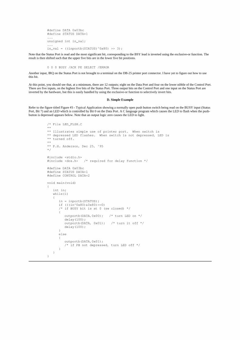
#define DATA 0x03bc#define STATUS DATA+1...unsigned int in_val;...in_val = ((inportb(STATUS)^0x80) >> 3);
Note that the Status Port is read and the most significant bit, corresponding to the BSY lead is inverted using the exclusive-or function. Theresult is then shifted such that the upper five bits are in the lower five bit positions.
0 0 0 BUSY /ACK PE SELECT /ERROR
Another input, IRQ on the Status Port is not brought to a terminal on the DB-25 printer port connector. I have yet to figure out how to usethis bit.
At this point, you should see that, at a minimum, there are 12 outputs; eight on the Data Port and four on the lower nibble of the Control Port.There are five inputs, on the highest five bits of the Status Port. Three output bits on the Control Port and one input on the Status Port areinverted by the hardware, but this is easily handled by using the exclusive-or function to selectively invert bits.
D. Simple Example
Refer to the figure titled Figure #3 - Typical Application showing a normally open push button switch being read on the BUSY input (StatusPort, Bit 7) and an LED which is controlled by Bit 0 on the Data Port. A C language program which causes the LED to flash when the push-button is depressed appears below. Note that an output logic zero causes the LED to light.
/* File LED_FLSH.C**** Illustrates simple use of printer port. When switch is** depressed LED flashes. When switch is not depressed, LED is** turned off.**** P.H. Anderson, Dec 25, '95*/
#include <stdio.h>#include <dos.h> /* required for delay function */
#define DATA 0x03bc#define STATUS DATA+1#define CONTROL DATA+2
void main(void){ int in; while(1) { in = inportb(STATUS); if (((in^0x80)&0x80)==0) /* if BUSY bit is at 0 (sw closed) */ { outportb(DATA,0x00); /* turn LED on */ delay(100); outportb(DATA, 0x01); /* turn it off */ delay(100); } else { outportb(DATA,0x01); /* if PB not depressed, turn LED off */ } }}
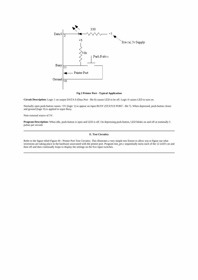
Fig 3 Printer Port - Typical Application
Circuit Description: Logic 1 on output DATA 0 (Data Port - Bit 0) causes LED to be off. Logic 0 causes LED to turn on.
Normally open push-button causes +5V (logic 1) to appear on input BUSY (STATUS PORT - Bit 7). When depressed, push-button closesand ground (logic 0) is applied to input Busy.
Note external source of 5V.
Program Description: When idle, push-button is open and LED is off. On depressing push-button, LED blinks on and off at nominally 5pulses per second.
E. Test Circuitry
Refer to the figure titled Figure #4 - Printer Port Test Circuitry. This illustrates a very simple test fixture to allow you to figure out whatinversions are taking place in the hardware associated with the printer port. Program test_prt.c sequentially turns each of the 12 LED's on andthen off and then continually loops to display the settings on the five input switches.
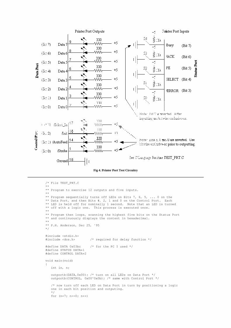
Fig 4. Printer Port Test Circuitry
/* File TEST_PRT.C**** Program to exercise 12 outputs and five inputs.**** Program sequentially turns off LEDs on Bits 7, 6, 5, ... 0 on the** Data Port, and then Bits #, 2, 1 and 0 on the Control Port. Each** LED is held off for nominally 1 second. Note that an LED is turned** off with a logic one. This process is executed once.**** Program then loops, scanning the highest five bits on the Status Port** and continuously displays the content in hexadecimal.**** P.H. Anderson, Dec 25, '95*/
#include <stdio.h>#include <dos.h> /* required for delay function */
#define DATA 0x03bc /* for the PC I used */#define STATUS DATA+1#define CONTROL DATA+2
void main(void){ int in, n;
outportb(DATA,0x00); /* turn on all LEDs on Data Port */ outportb(CONTROL, 0x00^0x0b); /* same with Control Port */
/* now turn off each LED on Data Port in turn by positioning a logic one in each bit position and outputing. */ for (n=7; n>=0; n++)
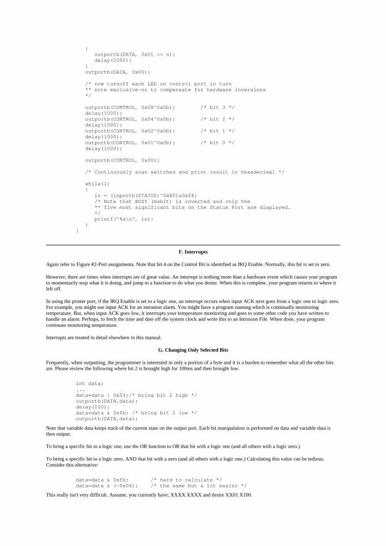
{ outportb(DATA, 0x01 << n); delay(1000); } outportb(DATA, 0x00);
/* now turnoff each LED on control port in turn ** note exclusive-or to compensate for hardware inversions */
outportb(CONTROL, 0x08^0x0b); /* bit 3 */ delay(1000); outportb(CONTROL, 0x04^0x0b); /* bit 2 */ delay(1000); outportb(CONTROL, 0x02^0x0b); /* bit 1 */ delay(1000); outportb(CONTROL, 0x01^0x0b); /* bit 0 */ delay(1000);
outportb(CONTROL, 0x00);
/* Continuously scan switches and print result in hexadecimal */
while(1) { in = (inportb(STATUS)^0x80)&0xf8; /* Note that BUSY (msbit) is inverted and only the ** five most significant bits on the Status Port are displayed. */ printf("%x\n", in); }}
F. Interrupts
Again refer to Figure #2-Port assignments. Note that bit 4 on the Control Bit is identified as IRQ Enable. Normally, this bit is set to zero.
However, there are times when interrupts are of great value. An interrupt is nothing more than a hardware event which causes your programto momentarily stop what it is doing, and jump to a function to do what you desire. When this is complete, your program returns to where itleft off.
In using the printer port, if the IRQ Enable is set to a logic one, an interrupt occurs when input ACK next goes from a logic one to logic zero.For example, you might use input ACK for an intrusion alarm. You might have a program running which is continually monitoringtemperature. But, when input ACK goes low, it interrupts your temperature monitoring and goes to some other code you have written tohandle an alarm. Perhaps, to fetch the time and date off the system clock and write this to an Intrusion File. When done, your programcontinues monitoring temperature.
Interrupts are treated in detail elsewhere in this manual.
G. Changing Only Selected Bits
Frequently, when outputting, the programmer is interested in only a portion of a byte and it is a burden to remember what all the other bitsare. Please review the following where bit 2 is brought high for 100ms and then brought low.
int data;...data=data | 0x04;/* bring bit 2 high */outportb(DATA,data);delay(100);data=data & 0xfb; /* bring bit 2 low */outportb(DATA,data);
Note that variable data keeps track of the current state on the output port. Each bit manipulation is performed on data and variable data isthen output.
To bring a specific bit to a logic one, use the OR function to OR that bit with a logic one (and all others with a logic zero.)
To bring a specific bit to a logic zero, AND that bit with a zero (and all others with a logic one.) Calculating this value can be tedious.Consider this alternative:
data=data & 0xfb; /* hard to calculate */data=data & (~0x04); /* the same but a lot easier */
This really isn't very difficult. Assume, you currently have; XXXX XXXX and desire XX01 X100.

data=data & (~0x20) | 0x10 | 0x04 & (~0x02) & (~0x01);
H. Ports on Newer PC's
A few words about the DIRECTION bit on the Control Port. I have seen PC's where this bit may be set to a logic "one" which turns aroundthe Data Port such that all of the Data leads are inputs. I have also seen PC's where this worked for only the lower nibble of the Data Port andother PC's where it did nothing. It is probably best not to use this feature. Rather, leave the DIRECTION bit set to logic "zero".
I. Differences In Printer Ports
The material discussed above is believed to be pretty generic; that is, common to all manufacturers.
You may well ask, "why would they be different. After all, programs such as WordPerfect must work on all machines." The answer is thatthe programmers who write such programs as WordPerfect do not get down to this low level of hardware detail. Rather, they write tointerface with the PC's BIOS.
The BIOS (Basic Input-Output System) is a ROM built in to the PC which makes all PC's appear the same. This is a pretty nice way for eachvendor to implement their design with a degree of flexibility.
An example is the port assignments discussed above. This data is read from the BIOS ROM when your PC boots up and written to memorylocations beginning at 0040:0008. Thus, the designers of WordPerfect don't worry about the port assignments. Rather, they read theappropriate memory location.
In the same way, they interface with the BIOS for printing. For example, if the designers want to print a character, the AH register is set tozero, the character to be printed is loaded into AL, the port (LPT1, LPT2, etc) is loaded into the DX register. They then execute a BIOS INT17h. Program control is then passed to the BIOS and which performs at the low level of hardware design which we are trying to work. TheBIOS varies from one hardware design to another; it's purpose is to work with the hardware. If inversions are necessary, it is done in theBIOS. When the BIOS has completed whatever bit sequencing is required to write the character to the printer, control is passed back to theprogram with status information in the AH register.
J. Summary
In summary, the printer port affords a very simple technique for interfacing with external circuitry. Twelve output bits are available, eight onthe Data Port and four on the lower nibble of the Control Port. Inversions are necessary on three of the bits on the Control Port. Five inputsare available on the Status Port. One software inversion is necessary when reading these bits.
II. Forcing an Interrupt on the Printer Port.
A. Introduction
This section describes how to use hardware interrupts using the printer port. The discussion closely follows programs prnt_int.c andtime_int.c
A hardware interrupt is a capability where a hardware event causes the software to stop whatever it is doing and to be redirected to a functionto handle the interrupt. When done, the program picks up where it left off. Aside from loosing time in executing the interrupt service routine,the operation of the main program remains unaffected by the interrupt.
This is quite powerful and although at first, the whole process may appear difficult to grasp, it is in fact quite simple.
Although this discussion focuses on using the interrupt associated with the printer port, the same technique may be adapted to exertinginterrupts directly on the ISA bus.
B. Interrupt Handler Table
When an interrupt occurs, the PC must know where to go to handle the interrupt.
The original 8088 PC design provided for up to 256 interrupts (0x00 - 0xff). This includes both hardware and software interrupts. Each ofthese 256 interrupt types has four bytes in a table beginning at memory location 0x00000. Thus, INT 0 uses memory locations 0x00000,0x00001, 0x00002, 0x00003, INT 1 uses the next four bytes in the table, etc. Note that INT 8 then uses the four bytes at 0x0020, INT 9begins at 0x0024, etc. This 1024 bytes (256x4) is termed the interrupt vector table.
These four bytes contain the address of where the PC is to go to when an interrupt occurs. Most of the table is loaded when you boot up themachine. The table may be added to or entries modified when you run various applications.
IBM reserved eight hardware interrupts beginning at INT 0x08 for interrupt expansion. These are commonly known as IRQ0 - IRQ7, theIRQ corresponding to the lead designations associated with the Intel 8259 which was used to control these interrupts. Thus, IRQ 0corresponds to INT 8, IRQ 1 corresponds to INT 9, etc.
Exercise. Use debug to examine the interrupt vector table which is assigned to IRQ 0 through IRQ 7.
-d 00000:0020 20
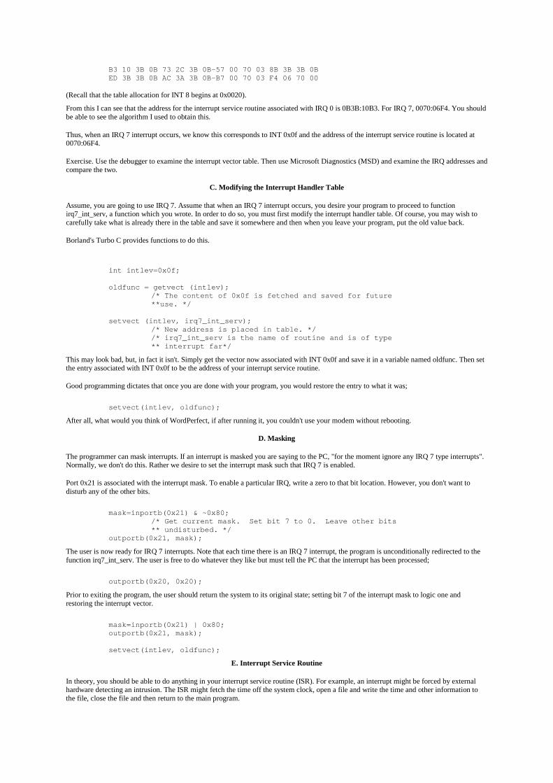
B3 10 3B 0B 73 2C 3B 0B-57 00 70 03 8B 3B 3B 0BED 3B 3B 0B AC 3A 3B 0B-B7 00 70 03 F4 06 70 00
(Recall that the table allocation for INT 8 begins at 0x0020).
From this I can see that the address for the interrupt service routine associated with IRQ 0 is 0B3B:10B3. For IRQ 7, 0070:06F4. You shouldbe able to see the algorithm I used to obtain this.
Thus, when an IRQ 7 interrupt occurs, we know this corresponds to INT 0x0f and the address of the interrupt service routine is located at0070:06F4.
Exercise. Use the debugger to examine the interrupt vector table. Then use Microsoft Diagnostics (MSD) and examine the IRQ addresses andcompare the two.
C. Modifying the Interrupt Handler Table
Assume, you are going to use IRQ 7. Assume that when an IRQ 7 interrupt occurs, you desire your program to proceed to functionirq7_int_serv, a function which you wrote. In order to do so, you must first modify the interrupt handler table. Of course, you may wish tocarefully take what is already there in the table and save it somewhere and then when you leave your program, put the old value back.
Borland's Turbo C provides functions to do this.
int intlev=0x0f;
oldfunc = getvect (intlev);/* The content of 0x0f is fetched and saved for future**use. */
setvect (intlev, irq7_int_serv);/* New address is placed in table. *//* irq7_int_serv is the name of routine and is of type** interrupt far*/
This may look bad, but, in fact it isn't. Simply get the vector now associated with INT 0x0f and save it in a variable named oldfunc. Then setthe entry associated with INT 0x0f to be the address of your interrupt service routine.
Good programming dictates that once you are done with your program, you would restore the entry to what it was;
setvect(intlev, oldfunc);
After all, what would you think of WordPerfect, if after running it, you couldn't use your modem without rebooting.
D. Masking
The programmer can mask interrupts. If an interrupt is masked you are saying to the PC, "for the moment ignore any IRQ 7 type interrupts".Normally, we don't do this. Rather we desire to set the interrupt mask such that IRQ 7 is enabled.
Port 0x21 is associated with the interrupt mask. To enable a particular IRQ, write a zero to that bit location. However, you don't want todisturb any of the other bits.
mask=inportb(0x21) & ~0x80;/* Get current mask. Set bit 7 to 0. Leave other bits** undisturbed. */
outportb(0x21, mask);
The user is now ready for IRQ 7 interrupts. Note that each time there is an IRQ 7 interrupt, the program is unconditionally redirected to thefunction irq7_int_serv. The user is free to do whatever they like but must tell the PC that the interrupt has been processed;
outportb(0x20, 0x20);
Prior to exiting the program, the user should return the system to its original state; setting bit 7 of the interrupt mask to logic one andrestoring the interrupt vector.
mask=inportb(0x21) | 0x80;outportb(0x21, mask);
setvect(intlev, oldfunc);
E. Interrupt Service Routine
In theory, you should be able to do anything in your interrupt service routine (ISR). For example, an interrupt might be forced by externalhardware detecting an intrusion. The ISR might fetch the time off the system clock, open a file and write the time and other information tothe file, close the file and then return to the main program.
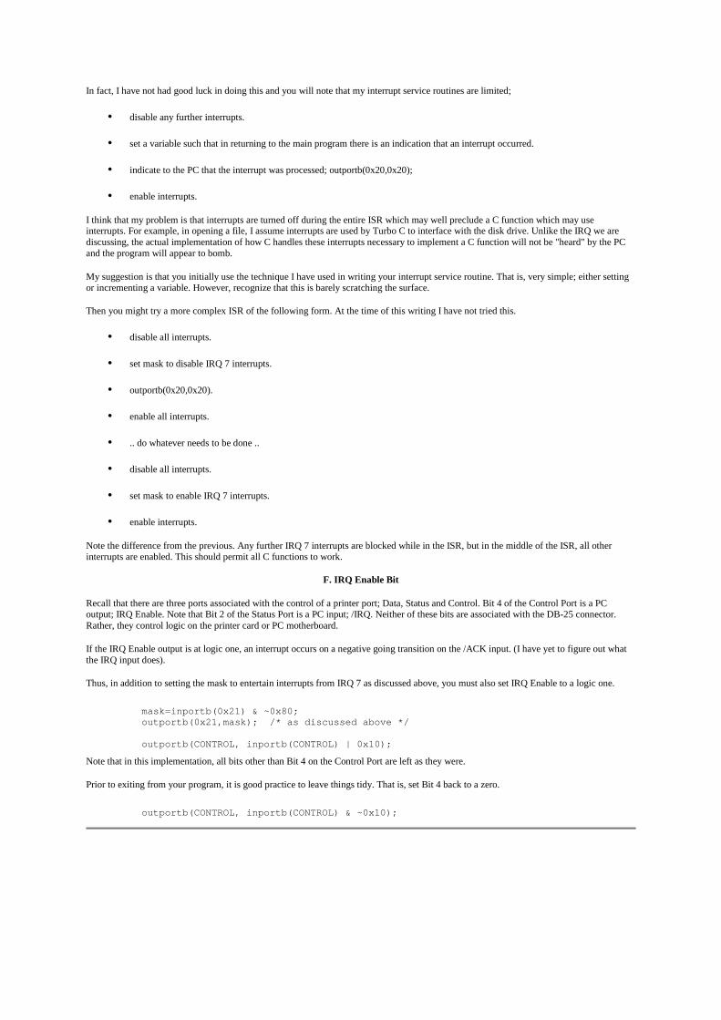
In fact, I have not had good luck in doing this and you will note that my interrupt service routines are limited;
• disable any further interrupts.
• set a variable such that in returning to the main program there is an indication that an interrupt occurred.
• indicate to the PC that the interrupt was processed; outportb(0x20,0x20);
• enable interrupts.
I think that my problem is that interrupts are turned off during the entire ISR which may well preclude a C function which may useinterrupts. For example, in opening a file, I assume interrupts are used by Turbo C to interface with the disk drive. Unlike the IRQ we arediscussing, the actual implementation of how C handles these interrupts necessary to implement a C function will not be "heard" by the PCand the program will appear to bomb.
My suggestion is that you initially use the technique I have used in writing your interrupt service routine. That is, very simple; either settingor incrementing a variable. However, recognize that this is barely scratching the surface.
Then you might try a more complex ISR of the following form. At the time of this writing I have not tried this.
• disable all interrupts.
• set mask to disable IRQ 7 interrupts.
• outportb(0x20,0x20).
• enable all interrupts.
• .. do whatever needs to be done ..
• disable all interrupts.
• set mask to enable IRQ 7 interrupts.
• enable interrupts.
Note the difference from the previous. Any further IRQ 7 interrupts are blocked while in the ISR, but in the middle of the ISR, all otherinterrupts are enabled. This should permit all C functions to work.
F. IRQ Enable Bit
Recall that there are three ports associated with the control of a printer port; Data, Status and Control. Bit 4 of the Control Port is a PCoutput; IRQ Enable. Note that Bit 2 of the Status Port is a PC input; /IRQ. Neither of these bits are associated with the DB-25 connector.Rather, they control logic on the printer card or PC motherboard.
If the IRQ Enable output is at logic one, an interrupt occurs on a negative going transition on the /ACK input. (I have yet to figure out whatthe IRQ input does).
Thus, in addition to setting the mask to entertain interrupts from IRQ 7 as discussed above, you must also set IRQ Enable to a logic one.
mask=inportb(0x21) & ~0x80;outportb(0x21,mask); /* as discussed above */
outportb(CONTROL, inportb(CONTROL) | 0x10);
Note that in this implementation, all bits other than Bit 4 on the Control Port are left as they were.
Prior to exiting from your program, it is good practice to leave things tidy. That is, set Bit 4 back to a zero.
outportb(CONTROL, inportb(CONTROL) & ~0x10);

Fig 5. Use of Parallel Printer Port For Interrupts
G. Programs
Program PRNT_INT.C simply causes a screen message to indicate an interrupt has occurred. Note that global variable "int_occurred" is setto false in the declaration. On interrupt, this is set to true. Thus, the code in main within the if(int_occurred) is only executed if a hardwareinterrupt did indeed occur.
Program TIME_INT.C is the same except for main. When the first interrupt occurs, the time is fetched off the system clock. Otherwise thenew time is fetched and the difference is calculated and displayed.
/*** Program PRNT_INT.C**
Uses interrupt service routine to note interrupt from printer port.The interrupt is caused by a negative on /ACK input on Printer Port.This might be adapted to an intrusion detector and temperature logger.
Note that on my machine the printer port is located at 0x0378 -0x037a and is associated with IRQ 7. You should run MicrosoftDiagnostics (MSD) to ascertain assignments on your PC.
** Name Address in Table**** IRQ2 0x0a** IRQ4 0x0c** IRQ5 0x0d** IRQ7 0x0f
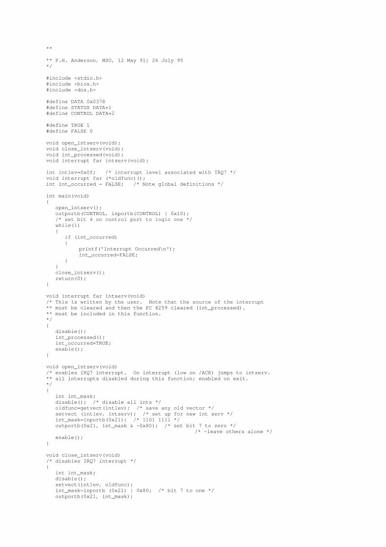
**
** P.H. Anderson, MSU, 12 May 91; 26 July 95*/
#include <stdio.h>#include <bios.h>#include <dos.h>
#define DATA 0x0378#define STATUS DATA+1#define CONTROL DATA+2
#define TRUE 1#define FALSE 0
void open_intserv(void);void close_intserv(void);void int_processed(void);void interrupt far intserv(void);
int intlev=0x0f; /* interrupt level associated with IRQ7 */void interrupt far (*oldfunc)();int int_occurred = FALSE; /* Note global definitions */
int main(void){ open_intserv(); outportb(CONTROL, inportb(CONTROL) | 0x10); /* set bit 4 on control port to logic one */ while(1) { if (int_occurred) {
printf("Interrupt Occurred\n"); int_occurred=FALSE;
} } close_intserv(); return(0);}
void interrupt far intserv(void)/* This is written by the user. Note that the source of the interrupt** must be cleared and then the PC 8259 cleared (int_processed).** must be included in this function.*/{ disable(); int_processed(); int_occurred=TRUE; enable();}
void open_intserv(void)/* enables IRQ7 interrupt. On interrupt (low on /ACK) jumps to intserv.** all interrupts disabled during this function; enabled on exit.*/{ int int_mask; disable(); /* disable all ints */ oldfunc=getvect(intlev); /* save any old vector */ setvect (intlev, intserv); /* set up for new int serv */ int_mask=inportb(0x21); /* 1101 1111 */ outportb(0x21, int_mask & ~0x80); /* set bit 7 to zero */
/* -leave others alone */ enable();}
void close_intserv(void)/* disables IRQ7 interrupt */{ int int_mask; disable(); setvect(intlev, oldfunc); int_mask=inportb (0x21) | 0x80; /* bit 7 to one */ outportb(0x21, int_mask);
enable();}
void int_processed(void)/* signals 8259 in PC that interrupt has been processed */{ outportb(0x20,0x20);}
/** Program TIME_INT.C*
Uses interrupt service routine to note interrupt from printer port.The interrupt is caused by a negative on /ACK input on Printer Port.
Calculates time and displays the time in ms between interrupts.
* P.H. Anderson, MSU, 10 Jan, '96*/
#include <stdio.h>#include <bios.h>#include <dos.h>#include <sys\timeb.h>
#define DATA 0x0378#define STATUS DATA+1#define CONTROL DATA+2
#define TRUE 1#define FALSE 0
void open_intserv(void);void close_intserv(void);void int_processed(void);void interrupt far intserv(void);
int intlev=0x0f; /* interrupt level associated with IRQ7 */void interrupt far (*oldfunc)();int int_occured=FALSE; /* Note global definitions */
int main(void){ int first=FALSE; int secs, msecs; struct timeb t1, t2; open_intserv(); outportb(CONTROL, inportb(CONTROL) | 0x10); /* set bit 4 on control port (irq enable) to logic one */ while(1) { if (int_occurred) {
int_occurred=FALSE; if (first==FALSE) /* if this is the first interrupt, just fetch the time */ { ftime(&t2); first=TRUE; } else { t1=t2; /* otherwise, save old time, fetch new */ ftime(&t2); /* and compute difference */ secs=t2.time - t1.time; msecs=t2.millitm - t1.millitm; if (msecs<0) { --secs; msecs=msecs+1000; } printf("Elapsed time is %d\n",1000*secs+msecs); }}
} close_intserv(); return(0); }
void interrupt far intserv(void) /* This is written by the user. Note that the source of the interrupt /* must be cleared and then the PC 8259 cleared (int_processed). /* must be included in this function. /*******/ { disable(); int_processed(); int_occurred=TRUE; enable(); }
void open_intserv(void) /* enables IRQ7 interrupt. On interrupt (low on /ACK) jumps to intserv. /* all interrupts disabled during this function; enabled on exit. /*******/ { int int_mask; disable(); /* disable all ints */ oldfunc=getvect(intlev); /* save any old vector */ setvect(intlev, intserv); /* set up for new int serv */ int_mask=inportb(0x21); /* 1101 1111 */ outportb(0x21, int_mask & ~0x80); /* set bit 7 to zero */
/* -leave others alone */ enable(); }
void close_intserv(void) /* disables IRQ7 interrupt */ { int int_mask; disable(); setvect(intlev, oldfunc); int_mask=inportb(0x21) | 0x80; /* bit 7 to one */ outportb(0x21,int_mask); enable(); }
void int_processed(void) /* signals 8259 in PC that interrupt has been processed */ { outportb(0x20, 0x20); }
Controlling the PC Parallel Port
The standard PC printer port is handy for testing and controlling devices. It provides an easy way toimplement a small amount of digital I/O. I like to use to during initial development of a product -- beforethe "real" hardware is ready, I can dummy up a circuit using the printer port, and thus get startedtesting my software.This source code module provides the low-level control of the port, implementing code to control 12outputs and read 5 inputs.
This code was written for Borland C/C++ v3.1, but you should be able to adapt it for other compilers.You can view the source code online, or download an archive (prn_io.zip) that contains PRN_IO.Cand PRN_IO.H. To use the module in your program, simply #include PRN_IO.H from wherever youneed to call the functions, and compile and link PRN_IO.C into your program.
View The Source Code
Download The Source Code

The following tables list the details of how the software interfaces to hardware port. Refer to thesource code itself for more information, or check out one of the links at the end of this page.
Printer Port AddressesPrinter Port Base Address
LPT1 0x0378 or 0x03BCLPT2 0x0278 or 0x0378LPT3 0x0278
Printer Port RegistersRegister Name AddressData Register Base + 0x00
Status Register Base + 0x01Control Register Base + 0x02
Data Register Bit DefinitionsBit Function Low High
7 (MSB) D7 0 16 D6 0 15 D5 0 14 D4 0 13 D3 0 12 D2 0 11 D1 0 1
0 (LSB) D0 0 1
Status Register Bit DefinitionsBit Function Low High
7 (MSB) Busy Busy Not Busy6 Acknowledge Nack Ack5 Paper Status No Paper Paper4 Selection Status Not Selected Selected3 Error Status No Error Error2 Not Used - -1 Not Used - -
0 (LSB) Not Used - -
Control Register Bit DefinitionsBit Function Low High
7 (MSB) Not Used - -6 Not Used - -5 Not Used - -4 Interrupt Control Interrupts Disabled Interrupts Enabled3 Select Selected Not Selected2 Initialize False True1 Auto Feed True False
0 (LSB) Strobe (Active-Low) True False
Source Code Implementation Notes:
• The code is written to use LPT1 at 0x0378; change it if you need to
• The code doesn't attempt to use interrupts

• The parallel port is also capable of enhanced modes (see the links below), but this codedoesn't attempt to use them
• This code assumes that the port is configured as a "standard" or "normal" port; configuring theport for EPP or ECP modes may or may not work
Other Parallel Port Information
What is EPP mode?
In the beginning, the parallel port on a PC was used only as an output port for a printer.However, several companies started to use is as a port to connect other devices, such asscanners or external storage devices. In such devices, you need to use the port also for input,to send data from the device to the computer. The original printer ports had only 8-bit outputcapability. However, there were two methods to implement the input capability to the portoriginally designed for output only.
The use of the control signal lines There are several lines used to carry the control signalsfrom the printer to the computer, such as Error, Select, Paper Empty or Busy. You can usethese lines to transfer 4-bit pieces of data. A byte (8 bits) of data is transferred in two"nibbles" (4 bits), from the external device to the computer. This is also referred to as Nibblemode.
The introduction of an I/O controller with the bi-directional 8-bit data port. This was ahardware change. This mode is referred to as Byte mode or Bi-directional mode. Bi-directional (byte) mode is faster than nibble mode. However there were needs for fastertransfer and two other methods were created.
The EPP (Enhanced Parallel Port) was developed by Intel, Xircom, Zenith Data System. Itlets the I/O controller take care of the handshake between the computer and the peripheral andthus frees the CPU from having to check the I/O port status every time it sends or receives apiece of data. This speeds up data transfer.
ECP (Extended Capacity Port) was developed by Hewlett-Packard and Microsoft. Itintroduced the data compression, FIFO buffer and other sophisticated features to the paralleldata transfer. All the features above were defined in the IEEE standard 1284-1994 "StandardSignaling Method for a Bi-directional Parallel Peripheral Interface for Personal Computers"You can find a very good introduction to this standard at: http://www.fapo .com/ieee1284.htm
UniversalFAST Cable - 10 ft
DirectParallel® Connection Cable
(2) PCs !"#!
FullSpecsMoreInfo
$69.95(Virtua
llyFREE)
BuyIt
Basic 4-BIT Cable - 10 ft
DirectParallel® Connection Cable
(2) PCs !"#!
FullSpecsMoreInfo
$19.95(Virtua
llyFREE)
BuyIt
Basic 4-BIT Cable - 25 ft
DirectParallel® Connection Cable
(2) PCs !"#!
FullSpecsMoreInfo
$29.95(Virtua
llyFREE)
BuyIt
Basic 4-BIT Cable - 50 ft
DirectParallel® Connection Cable
(2) PCs !"#!
FullSpecsMoreInfo
$49.95(Virtua
llyFREE)
BuyIt
DirectParallel® Universal FAST Cable
• Share Your Internet Connection
• FREE Internet Connection Sharing Software
• Connect ANY (2) PCs Running Win95/98/98SE/Me/2000/XPQuickly and Easily -- Built-in Connectivity and Networking
• High-Speed Ethernet-like Access -- Up to 500 KBytes/sec.+Data Transfer Speed (30 MB/minute)
• Transfer Files Quickly and Easily -- Move large files around
• Share Network Resources -- CDROMs (RW), Printers, etc...
• Fully Optimized for Windows 95/98/98SE/Me/2000/XPDirect Cable Connection (DCC)
• Access Your Office LAN Using Your Notebook PC
• Up to ten times faster than our Basic 4-Bit DirectParallel Cable
• Laptop to Desktop Connectivity
• Supported by All Major File Transfer & Remote Access SoftwareApplications
• One Year Limited Warranty
• Free Technical Support
• Standard Length is 10 ft -- Can be extended to 100 ft or more usingour IEEE 1284 25 ft Extension Cables
Comes WithFREE Internet
Connection SharingSoftware and
Personal FirewallWinRoute LiteAn $80 Value
DirectParallel® Basic 4-Bit Cable
• Share Your Internet Connection for only $20
• FREE Internet Connection Sharing Software
• Connect ANY (2) PCs Running Wind95/98/98SE/Me/2000/XPQuickly and Easily -- Built in Connectivity and Networking
• Slower than the Universal Fast Cable but also works on all PCsTypical Data Transfer Rates of 40 - 70 Kbytes/sec.(2.4 MB - 4.2 MB/minute)
• Transfer Files -- Move large files between PCs
• Share Network Resources -- CDROMs (RW), Printers, etc...
• Fully Optimized for Windows 95/98/98SE/Me/2000/XPDirect Cable Connection (DCC)
• Access Your Office LAN Using Your Notebook PC
• Laptop to Desktop Connectivity
• Supported by All Major File Transfer & Remote Access SoftwareApplications
• One Year Limited Warranty
• Free Technical Support
• Standard Length is 10 ft
• Longer Lengths Now Available -- 25 ft and 50 ft versions
• For FAST Data Transfer -- Use our Universal Fast Cable
WHAT ARE THE DIFFERENCES BETWEEN THE DIRECTPARALLEL®
UNIVERSAL FAST AND BASIC 4-BIT CABLES?The DirectParallel® Universal Fast Cable provides the highest speed connections across thefull spectrum of available parallel ports automatically. This cable has intelligent circuitry builtinto it that automatically identifies the parallel port of each computer and will optimize thedata communications for the fastest possible speeds between the two computers. Theintelligent circuitry is powered by the computer - so, no separate battery or AC adapter powersource is required. The maximum burst transfer data rate for this cable can be over 500KBytes/sec..
The DirectParallel® Basic Cable is an economical slower version of the Universal Fast Cable.The maximum burst transfer data rate for this cable range between 50 Kbytes/sec. to about100 Kbytes per second.
So, connections between computers using the DirectParallel® Universal cable can be up to 10times faster than the Basic Cable and only the Universal cable optimizes the connection totake advantage of high speed EPP and ECP parallel ports.
Of course, data transfer rates are dependent upon PC type, CPU speed, parallel port type, datacompressibility, Windows 95/98/ME/2000, and other protocol overhead. Windows

95/98/ME/2000 typically uses data compression when using Direct Cable Connect - thereforehighly compressible files will transfer the fastest.
Printer Mode is the most basic mode. It is a Standard Parallel Port in forward mode only. It has no bi-directional feature, thus Bit 5 of the Control Port will not respond. Standard & Bi-directional (SPP) Modeis the bi-directional mode. Using this mode, bit 5 of the Control Port will reverse the direction of the port,so you can read back a value on the data lines.
In conclusione tutti i dati (sia pure con qualche variante sul significato di SPP) concordao sulle seguenti informazioni:
La porta PARALLELA è PARALLELA solo in uscita nel senso che SCRIVE 8 bit alla volta, ma nella prima versione non aveva nessunapossibilità di LEGGERE…
SPP/EPP/ECPThe original specification for parallel ports was unidirectional, meaning that data only traveled in onedirection for each pin. With the introduction of the PS/2 in 1987, IBM offered a new bidirectionalparallel port design. This mode is commonly known as Standard Parallel Port (SPP) and hascompletely replaced the original design. Bidirectional communication allows each device to receivedata as well as transmit it. Many devices use the eight pins (2-9) originally designated for data. Usingthe same eight pins limits communication to half-duplex, meaning that information can only travel inone direction at a time. But pins 18-25, originally just used as grounds, can be used as data pins also.This allows for full-duplex (both directions at the same time) communication.
Enhanced Parallel Port (EPP) was created by Intel, Xircom and Zenith in 1991.EPP allows for much more data, 500K to 2 MB, to be transferred each second. It wastargeted specifically towards non-printer devices that would attach to the parallel port,particularly storage devices that needed the highest possible transfer rate.
Close on the heels of the introduction of EPP, Microsoft and Hewlett Packard jointlyannounced a specification called Extended Capabilities Port (ECP) in 1992. WhileEPP was geared towards other devices, ECP was designed to provide improvedspeed and functionality for printers.
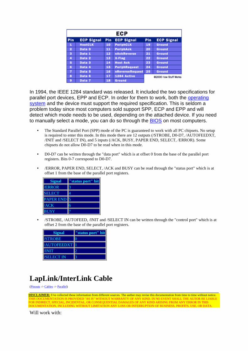
In 1994, the IEEE 1284 standard was released. It included the two specifications forparallel port devices, EPP and ECP. In order for them to work, both the operatingsystem and the device must support the required specification. This is seldom aproblem today since most computers sold support SPP, ECP and EPP and willdetect which mode needs to be used, depending on the attached device. If you needto manually select a mode, you can do so through the BIOS on most computers.
• The Standard Parallel Port (SPP) mode of the PC is guaranteed to work with all PC chipsets. No setupis required to enter this mode. In this mode there are 12 outputs (/STROBE, D0-D7, /AUTOFEEDXT,/INIT and /SELECT IN), and 5 inputs (/ACK, BUSY, PAPER END, SELECT, /ERROR). Somechipsets do not allow D0-D7 to be read when in this mode.
• D0-D7 can be written through the "data port" which is at offset 0 from the base of the parallel portregisters. Bits 0-7 correspond to D0-D7.
• /ERROR, PAPER END, SELECT, /ACK and BUSY can be read through the "status port" which is atoffset 1 from the base of the parallel port registers.
Signal "status port" bit/ERROR 3SELECT 4PAPER END 5/ACK 6BUSY 7
• /STROBE, /AUTOFEED, /INIT and /SELECT IN can be written through the "control port" which is atoffset 2 from the base of the parallel port registers.
Signal "status port" bit/STROBE 0/AUTOFEEDXT 1/INIT 2/SELECT IN 3
LapLink/InterLink Cable(Pinouts -> Cables -> Parallel)
DISCLAIMER: I\'ve collected these information from different sources. The author may revise this documentation from time to time without notice.THIS DOCUMENTATION IS PROVIDED "AS IS" WITHOUT WARRANTY OF ANY KIND. IN NO EVENT SHALL THE AUTOR BE LIABLEFOR INDIRECT, SPECIAL, INCIDENTAL, OR CONSEQUENTIAL DAMAGES OF ANY KIND ARISING FROM ANY ERROR IN THISDOCUMENTATION, INCLUDING WITHOUT LIMITATION ANY LOSS OR INTERRUPTION OF BUSINESS, PROFITS, USE, OR DATA.
Will work with:

• LapLink from Travelling Software
• MS-DOS v6.0 InterLink from Microsoft
• Windows 95 Direct Cable connection from Microsoft
• Norton Commander v4.0 & v5.0 from Symantec
(To Computer 1).
(To Computer 2).
25 PIN D-SUB MALE to Computer 1.25 PIN D-SUB MALE to Computer 2.
Name Pin Pin NameData Bit 0 2 15 ErrorData Bit 1 3 13 SelectData Bit 2 4 12 Paper OutData Bit 3 5 10 AcknowledgeData Bit 4 6 11 BusyAcknowledge 10 5 Data Bit 3Busy 11 6 Data Bit 4Paper Out 12 4 Data Bit 2Select 13 3 Data Bit 1Error 15 2 Data Bit 0Reset 16 16 ResetSelect 17 17 SelectSignal Ground 18-25 18-25 Signal Ground
Esiste anche un'altro cavo che sembrerebbe andare bene,ma in tutte le pagine che abbiamo trovato viene associatosolo al Commodore Amiga. E’ il cavo ParNet…
ParNet Cable(Pinouts -> Cables -> Parallel)
DISCLAIMER: I\'ve collected these information from different sources. The author may revise this documentation from time to time without notice.THIS DOCUMENTATION IS PROVIDED "AS IS" WITHOUT WARRANTY OF ANY KIND. IN NO EVENT SHALL THE AUTOR BE LIABLEFOR INDIRECT, SPECIAL, INCIDENTAL, OR CONSEQUENTIAL DAMAGES OF ANY KIND ARISING FROM ANY ERROR IN THISDOCUMENTATION, INCLUDING WITHOUT LIMITATION ANY LOSS OR INTERRUPTION OF BUSINESS, PROFITS, USE, OR DATA.

(To Computer 1).
(To Computer 2).
25 PIN D-SUB MALE to Computer 1.25 PIN D-SUB MALE to Computer 2.
Name Pin Pin NameData Bit 0 2 2 Data Bit 0Data Bit 1 3 3 Data Bit 1Data Bit 2 4 4 Data Bit 2Data Bit 3 5 5 Data Bit 3Data Bit 4 6 6 Data Bit 4Data Bit 5 7 7 Data Bit 5Data Bit 6 8 8 Data Bit 6Data Bit 7 9 9 Data Bit 7Acknowledge + Select 10+13 10+13 Acknowledge + SelectBusy 11 11 BusyPaper Out 12 12 Paper OutSignal Ground 17-25 17-25 Signal Ground
Cables That Are Compatible with Direct Cable Connection (Q142324)
The information in this article applies to:
• Microsoft Windows Millennium Edition
• Microsoft Windows 98 Second Edition
• Microsoft Windows 98
• Microsoft Windows 95
SUMMARY
You can use the Direct Cable Connection tool to establish a direct serial or parallel cableconnection between two computers. Windows supports serial null-modem standard (RS-232) cables and the following parallel cables for use with Direct Cable Connection:
• Standard or basic 4-bit cables
• Enhanced Capabilities Port (ECP) cables
• Universal Cable Module (UCM) cables

Parallel cable connections are faster than serial cable connections. Use a serial cable withDirect Cable Connection only if a parallel port or cable is unavailable.
MORE INFORMATION
ECP cables work on computers with ECP-enabled parallel ports. ECP must be enabled inboth computers' CMOS settings for parallel ports that support this feature. ECP cablesallow data to be transferred more quickly than standard cables. Note that bothcomputers must support ECP in order to use ECP cables.
UCM cables support connecting different types of parallel ports. Using a UCM cablebetween two ECP-enabled ports allows the fastest possible data transfer between twocomputers.
Pin Connections for a Serial CableThis section describes the wiring specifications for serial InterLink cables that can beused with Direct Cable Connection. To make a serial InterLink cable, make a serial cablewith either a 9-pin or 25-pin female connector on both ends, and wire the cable asfollows:
9-pin 25-pin 25-pin 9-pinDescription----------------------------------------------------------------------pin 5 pin 7 <------> pin 7 pin 5Ground-Groundpin 3 pin 2 <------> pin 3 pin 2 Xmit-Rcvpin 7 pin 4 <------> pin 5 pin 8 RTS-CTSpin 1 and 6 pin 6 <------> pin 20 pin 4 DSR-DTRpin 2 pin 3 <------> pin 2 pin 3 Xmit-Rcvpin 8 pin 5 <------> pin 4 pin 7 CTS-RTSpin 4 pin 20 <------> pin 6 pin 1 and 6 DTR-DSR
• The Ground (GRD) line is the reference signal ground for all other lines.
• The Transmit Data (TD) line is used for sending data.
• The Receive Data (RD) line is used for receiving data.
• The RTS (Request To Send) line is used by the data terminal equipment (DTE) to indicate thatit is ready to send data.
• The CTS (Clear To Send) line is used by the data communications equipment (DCE) toindicate that it is ready to receive data.
• The DSR (Data Set Ready) line is used by the DCE to indicate that it is ready to communicate.
• The DTR (Data Terminal Ready) line is used by the DTE to indicate that the DCE shouldinitiate communication.

Pin Connections for a Parallel CableThis section describes the wiring specifications for parallel InterLink cables that can beused with Direct Cable Connection. To make a parallel InterLink cable, make a parallelcable with male DB-25 connectors at both ends, and wire the cable as follows:
25-pin 25-pin Description------------------------------------------pin 2 <------> pin 15 N/Apin 3 <------> pin 13 N/Apin 4 <------> pin 12 N/Apin 5 <------> pin 10 N/Apin 6 <------> pin 11 N/Apin 15 <------> pin 2 N/Apin 13 <------> pin 3 N/Apin 12 <------> pin 4 N/Apin 10 <------> pin 5 N/Apin 11 <------> pin 6 N/Apin 25 <------> pin 25 Ground-Ground
Linux Networking HOWTOPrev Chapter 13. Cables and Cabling Next
13.2. Parallel port cable (PLIP cable)If you intend to use the PLIP protocol between two machines, then this cable will work foryou (irrespective of what sort of parallel ports you have installed).Pin Name pin pinSTROBE 1*D0->ERROR 2 ----------- 15D1->SLCT 3 ----------- 13D2->PAPOUT 4 ----------- 12D3->ACK 5 ----------- 10D4->BUSY 6 ----------- 11D5 7*D6 8*D7 9*ACK->D3 10 ----------- 5BUSY->D4 11 ----------- 6PAPOUT->D2 12 ----------- 4SLCT->D1 13 ----------- 3FEED 14*ERROR->D0 15 ----------- 2INIT 16*SLCTIN 17*GROUND 25 ----------- 25
Notes:
• Do not connect the pins marked with an asterisk `*'.
• Extra grounds are 18,19,20,21,22,23 and 24.
• If the cable you are using has a metallic shield, it should be connected to the metallicDB-25 shell at one end only.
Warning: A miswired PLIP cable can destroy your controller card. Be very careful! Be sure to double checkevery connection to ensure that you don't cause yourself any unnecessary work or heartache.
While you may be able to run PLIP cables for long distances, you should avoid it if you can.The specifications for the cable allow for a cable length of about 1 meter or so. Please be very
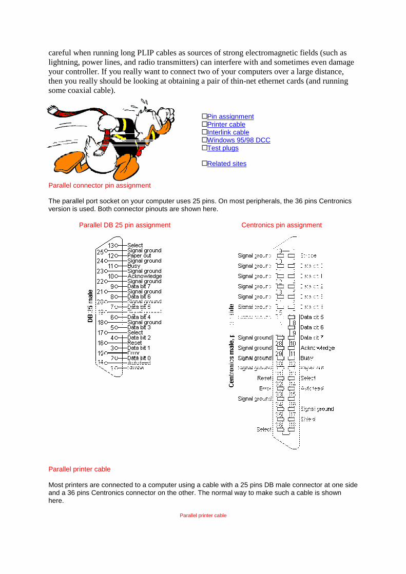
careful when running long PLIP cables as sources of strong electromagnetic fields (such aslightning, power lines, and radio transmitters) can interfere with and sometimes even damageyour controller. If you really want to connect two of your computers over a large distance,then you really should be looking at obtaining a pair of thin-net ethernet cards (and runningsome coaxial cable).
Pin assignmentPrinter cableInterlink cableWindows 95/98 DCCTest plugs
Related sites
Parallel connector pin assignment
The parallel port socket on your computer uses 25 pins. On most peripherals, the 36 pins Centronicsversion is used. Both connector pinouts are shown here.
Parallel DB 25 pin assignment Centronics pin assignment
Parallel printer cable
Most printers are connected to a computer using a cable with a 25 pins DB male connector at one sideand a 36 pins Centronics connector on the other. The normal way to make such a cable is shownhere.
Parallel printer cable
Line 25 DB male CentronicsStrobe 1 1Data bit 0 2 2Data bit 1 3 3Data bit 2 4 4Data bit 3 5 5Data bit 4 6 6Data bit 5 7 7Data bit 6 8 8Data bit 7 9 9Acknowledge 10 10Busy 11 11Paper out 12 12Select 13 13Autofeed 14 14Error 15 32Reset 16 31Select 17 36Signal ground 18 33Signal ground 19 19 + 20Signal ground 20 21 + 22Signal ground 21 23 + 24Signal ground 22 25 + 26Signal ground 23 27Signal ground 24 28 + 29Signal ground 25 16 + 30Shield Shield Shield + 17
Interlink and Windows 95/98 DCC parallel cable
The following cable can be used with file transfer and network programs like LapLink and InterLink.The cable uses the parallel port which makes it possible to achieve higher throughput than with aserial connection at the same low costs. The cable is at least compatible with the following software.
Laplink from Travelling softwareMS-DOS v 6.0 InterLinkWindows 95 direct cable connectionNorton Commander v 4.0 and v 5.0

Interlink and Windows 95/98 DCC parallel cable
7A. Parallel Port Laplink Cable Pinouts
Laplink cable is used to link two PCs with MSDOS 6.0 or later, very effectively by usingINTERSVR.EXE (on Host) and INTERLNK.EXE (on GUEST) PCs. But it can also be used todata-transfer at faster speed with DCC Feature of Win9x/Me/2000.
If you are seeking to buy a Parallel port Laplink cable, or trying to make your own cable,you should know what pins need to be switched in order to make it. Below is a chart ofwhat pins go to what on the other end. Only 18 pins are used in a Laplink Cable,therefore I will only show those eighteen here.
To make this cable we need1. TWO numbers of DB-25 Male Sockets.2. Shielded Cable with 18 cores (lines of wires).
Chart#5
DCC Parallel Laplink Cable Pinouts.
Male DB-25 ==>> Male DB-25
1 Both Not used
2 to 15
3 to 13
4 to 12
5 to 10
6 to 11
7 Both Not used
8 Both Not used
9 Both Not used
10 to 5
11 to 6
12 to 4
13 to 3
14 Both Not used
15 to 2
16 Both Not used
17 to 19
18 to 18
19 to 17
20 Both Not used
21 to 21
22 to 22
23 to 23
24 Both Not used
25 to 25
Pinbody* to Pinbody
* = In my cable one wire was attached to the metal body of the Male pins on both sides.Total 18 wired cable is necessary for this cable including one wire for Body of the pin too.
IMP: On above information, I was congratulated by Don Schuman of www.lpt.com,Parallel Technologies, the inventors/developers of the parallel version of the Windows
95/98/2000 Direct Cable Connection (DCC) feature and drivers. He has offered us a smallnicely animated software, DirectParallel Connection Monitor Utility, for all the DCC users
to troubleshoot and test DCC connection and cable on both the computers. It alsoprovides detailed information about the connection, the cable being used for the
connection, the I/O mode (4-bit, 8-bit, ECP), the parallel port types, I/O address, andIRQ. The company, Parallel Technologies, is associated with the Microsoft for DCC andcan be seen listed in Win9x Help (Index+Direct Cable Connection+ordering cables).
SPEED: Parallel port Laplink cable is little faster than Serial port Cable because of morenumbers of cores of wires used in Parallel port cable (25 pin) than Serial port Cable (9pins). The expected speed is 2000kbytes/second but it is extremely dependent on the
different quality chipset structure of Parallel Ports on different makes of theMotherboards. Some even reported me the lowest speed of 60kb/sec even though all
other settings are correct. Its recommended that you setup LPT1 mode as only"ECP/EPP" or "ECP" mode in bios to get better speed, and not the "Normal" (4bit/8bit)modes. The latest tests done by me on modern motherboard proved that serial port
transfers are equal or little slower than parallel ports.
Here's parallel information. BTW, I've found that parallel lap-linkcables are often called "Turbo LapLink" cables.
1 - 12 - 153 - 134 - 125 - 106 - 117 nc8 nc9 nc10 - 511 - 612 - 413 - 314 - 1415 - 216 - 1617 - 1718 nc19 nc20 nc
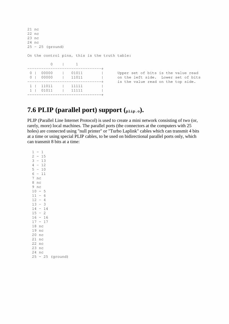
21 nc22 nc23 nc24 nc25 - 25 (ground)
On the control pins, this is the truth table:
0 | 1--------------------------------+ 0 | 00000 | 01011 | Upper set of bits is the value read 0 | 00000 | 11011 | on the left side. Lower set of bits--------------------------------+ is the value read on the top side. 1 | 11011 | 11111 | 1 | 01011 | 11111 |--------------------------------+
7.6 PLIP (parallel port) support (plip.o).PLIP (Parallel Line Internet Protocol) is used to create a mini network consisting of two (or,rarely, more) local machines. The parallel ports (the connectors at the computers with 25holes) are connected using "null printer" or "Turbo Laplink" cables which can transmit 4 bitsat a time or using special PLIP cables, to be used on bidirectional parallel ports only, whichcan transmit 8 bits at a time:
1 - 1 2 - 15 3 - 13 4 - 12 5 - 10 6 - 11 7 nc 8 nc 9 nc 10 - 5 11 - 6 12 - 4 13 - 3 14 - 14 15 - 2 16 - 16 17 - 17 18 nc 19 nc 20 nc 21 nc 22 nc 23 nc 24 nc 25 - 25 (ground)