parallel cmm - a new development: mechanical design and ... · cmm (serial) and additional 3...
TRANSCRIPT
Proceedings of the 33rd ISR (International Symposium on Robotics) October 7 – 11, 2002
Parallel CMM - A New Development: Mechanical Design and Calibration Results
Gheorghe Olea, Osamu Sato, Kyoshi Takamasu,
[email protected] [email protected] [email protected] The University of Tokyo
Dept. of Precision Engineering 7-3-1, Hongo, Bunkyo-ku, 113-8656 Tokyo,
Japan
ABSTRACT Coming from the actual and future measurement needs in the product and technological developments, a new experimental device for Parallel CMM (Coordinates Measuring Machine with Parallel Mechanism structure) was redesigned from mechanical point of view, and the results of its calibration process are presented in this paper. First of all, to justify our research topic, a short analysis is included, taking into account the actual/further CMM’s market trends, from both–customers’ requirements and builders’ possibilities. Next, as a possible solution to encompass and pass the actual CMM (serial) structure’s limitations (speed, accuracy, weight, etc), a linear actuated 3-3P(SS/SS) parallel mechanism structure is developed, by analysing and proving its suitable structure. Adding new improvements in the general mechanical design conception at previous experimental models (especially, for magnetically spherical joints) the number and level of the geometric errors became smaller without high costs of the manufacturing/assembly operations, and the accuracy of the mechanism was increased. Three proposals for the calibration models (with 9, 16 and 39 parameters) using for measurements another CMM (serial) and additional 3 sensors are presented, for the determination of the mechanism’s geometric (static) errors in the working space area. Volumetric accuracy of the mechanism (errors) was determined by simulation in these cases and the numerical results are presented in a table and graphically in pictures for the best one (16). Keywords: Coordinate Measuring Machines, Parallel Mechanisms Design, Calibration
1 INTRODUCTION Measurement System Users’ Needs The needs for every day life and the progress in science and technique, claims more and more new products. As a result, an increased number of pieces/assemblies (1), with very different geometrical and physical features, like: shape, size, hardness, roughness, etc. comes from the manufacturing or/and assembly processes, and must to be controlled in accordance with their working requirements (as a result of the design process), as fast as possible. But,
some times, the products or components, especially belonging to the automotive (cars), aeronautic (aircrafts), space (missile), etc. areas have even a complex shape (2) and/or big size (3). (Dimensional) size and shape (profile) are two important features for a product, and play crucial role in the total control time of the final product, influencing the product’s costs. More and more needs for doing this control operation are seeing to be on the shop floor (4) and if it is possible integrated in the flexible process line. As a result, the size and weight of the control systems is better to be smaller. The dimensional size resulting from the manufacturing processes have different measured values, and must to be in a desired interval of tolerance (error) imposed by the designers, to fulfil work requirements. But, some times, the design requirements (tolerances) are very high, and reach extreme limits. Surprisingly (or, not), nowadays as a result of the continuously increasing of the new manufacturing technologies (5) some of these limits could be attained or will be, in the near future. Shortly, summarizing, all above-actual/further user’s measurement needs (requirements), from the dimensional control point of view, the requirements for the specific systems (Coordinate Measuring Machines) builders and their machines, can be stated as follows: a) Higher measurement speed is needed-as a result
of the continuously increasing product production (1), or in the case (2) or (3),
b) Smaller size (weight) is better for the systems -to be integrated in the flexible lines on the shop floor (4), for (2) or (3) types, too,
c) Higher accuracy is imperative-as a result of the progress in the manufacturing/ assembly processes area (5).
CMM’ builders’ possibilities and solutions Actual, industrial widespread systems for control/inspection the dimensional size and/or shape profile for one product, by measurements, in order to take a decision if after the manufacturing systems they should be approved or rejected on piece, or in other cases after some tests, or only to be redesigned one piece, etc are commonly called Coordinate
Proceedings of the 33rd ISR (International Symposium on Robotics) October 7 – 11, 2002
Measuring Machines (CMMs). They are automated measurement and inspection systems wich in the actual, and for long time, typical structure, comprise mainly, a 3DOF (in translation-X, Y, Z) Positioning Device (PD) and a Processing System (PS) to calculate and control one Probe (P), and reporting the results related to the movement (measurments) task. For carrying out measurements on a workpiece(WP) supported on a table, PD moves the Probe between the points of interest, and by measuring the axial displacement of the probe along each of the three orthogonal axes (identified as the X, Y, and Z axes) by the sensors help, the results of the measurements can be obtained. Many comercial products varying from the size, facilities and of course performances are on the market.Among consacrated important companies we can remind e.g. MITUTOYO, ZEISS, etc. It is easy to understand, that any adequate control/ inspection machine or equipment (CMMs, also) for checking the dimensional or/and shape accuracy of one product, must have a level of the (positioning) accuracy higher than all that of the machines used for the product’s manufacturing. Unfortunately, like all manufacturing machines tools, in the actual very common structure of CMMs, they are for long time, serial stacked designed, taking in to account the mechanical architecture, and working with an accuracy, speed, and having the weight that seems to be at one limit, even a lot of researches are doing to improve them, because, in general: a) The speed of movement (and measurement)
depends, mainly, on the actuators power and on the weight of the components. It can be increased: 1) by increasing the power of actuators or/and, 2) by decreasing the weight (size) of components in movements.
But, by increasing the actuators’ power (1), generally, the size (and/or weight), must to be increased (if no revolutionary design happened in the actuators area). On the other hand, the decreasing weight (size) in the components movements (2) will be possible only, by the decreasing actuators’ size (weight), because, the CMM’s main component – actuators, also move. These two possible solutions will be in conflict all the time and the requirement for increasing the speed can not be fulfilled. b) A higher position accuracy of movement
(positioning) depends, mainly, of the static and dynamic mechanism’s errors. In order to increase the actual accuracy, the improvement of its static and dynamic stiffness is needed. There are two solutions, also: 1) the increasing of the components’ stiffness (weight, size) and/or 2) the decreasing the components’ in moving speed.
But, for achieve these both requirements we seem to be in the same trouble as in the previous requirement (a) and we cannot fulfil nor this requirement from the CMM users, as well, c) Bigger shape/size can be measured accurately in
the present structure (serial), only with the price of 1) increasing the components’ dimensions and overall size of the system and/or, consequently
(or not), 2) by increasing the weight of whole CMM’s system.
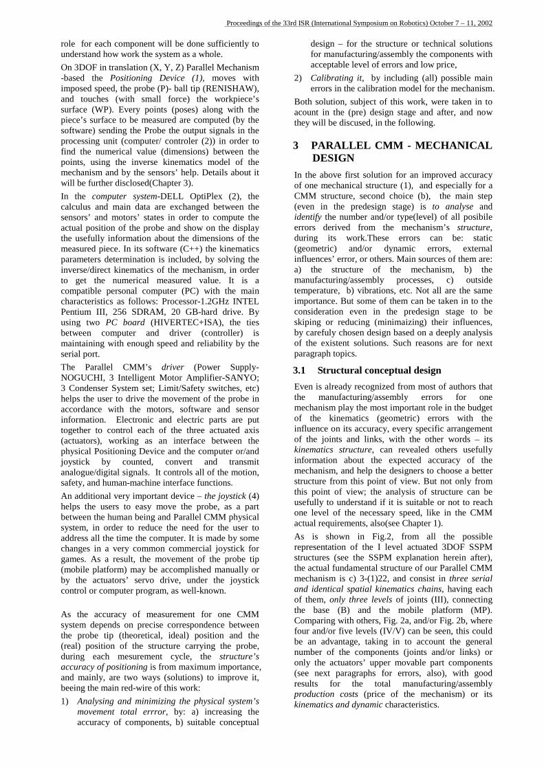
Indeed, to achieve the necessary accuracy in such case, (1) is necessary solution coming from the evident design considerations and (2) is needed for the stiffness requirements. It is easy to observe from the above short analysis that the CMM builders’ actual possibilities for measurements, resulting from the CMM’s performances are not enough for the actual/future CMM customer requirements, because their Serial Mechanism Structures (SMS) possibilities (performances) are at the limit and the solutions for next their improvements, cannot be done (shown), due to the inherent limitations (drawbacks) coming from their specific structure(serial). Another solution As it is easy to observe from the above short analysis of the CMM market, the user requirements and the builder actual possibilities are not the same. Former being much higher or/and smaller then second can offer. The actual inherent solutions and presented from the specific literature selected cannot be satisfactory at all. As a result, new solutions are needed to be given to the CMM’s builders; perhaps new concepts in the design of control/inspection systems. Maybe one of them is herein in this paper and will be presented in the following. Based on our experience coming from the previous research results, our proposal is to change actual Mechanical structure (using Serial Mechanism) and the use of Parallel Mechanism (PM) for CMM mechanical structure. The Parallel Mechanism (PM) structures [1],[2], etc have already proved inherent advantages coming from the special arrangement of the joints and links, comparing with Serial Mechanism(SM) structures. In the last time, many applications are focused on this structure hoping to be a last chance for improving dynamic behaviour and accuracy of the machines, equipments and/or others systems. Indeed, by an adequate design based on deeply research studies, high performances can be obtained in terms of accuracy, speed (acceleration), or carry load minimising some drawbacks, like workspace volume or difficult control. In the particular case of CMMs, the specific features (requirements) must be fulfilled from its spatial mechanism, as is underlined in the following table (Tab. 1), by comparing the existing main kinematics structures of mechanisms – serial (S) and parallel (P), respectively: Tab. 1 CMM main features: Serial (S) and Parallel (P) mechanisms comparison
Type Features
S P
Accuracy low high Speed small high
Direct Kinematics easy difficult Inverse Kinematics difficult easy Workspace big small
Proceedings of the 33rd ISR (International Symposium on Robotics) October 7 – 11, 2002
Among these important and necessary minimum requirements for CMM Parallel Mechanism structure, an additional adequate model of errors, specific for its calibration process, is also of the maximum importance. Aims and targets The aims and objectives of this paper are to promote the advantages (and to disclose the possible shortcuts) of a Parallel Mechanism structure in order to be used like a Coordinate Measuring Machine. By (re) designing a previous experimental model and trying to calibrate it, some of its new features will be revealed, being an additional work in to a next step to draw the Parallel-CMM to the CMM’s builder attention. In this paper, after this introductory part, taking into account the CMM’s customer and builder needs, a general overview of the previous and actual Parallel CMM models firstly, will be shown. Secondly, changes from mechanical point of view in design are disclosed for the actual Parallel CMM experimental model. Next, its calibration process is presented, together with some results. At the end, short conclusions and future thoughts are put, as basis for the development of next steps.
2 PARALLEL CMM – OVERVIEW 2.1 Previous models The Parallel Mechanisms use has gained in its importance mainly in the last few years, when an “explosion” in the application area was observed from the specific literature [1],[2], despite their relative long life, when about 30 years ago, GOUGH designed, and after that STEWART promoted in the scientific world one fundamental mechanism [3]. The research and implementation studies for PM in the measurement and inspection area, specifically for CMM task has only just begun few years ago, and today are modest. Most of them have focussed on the prospective implementation possibilities rather than the direct industrial applications. Hence, they have resulted in only one commercially exploitable machine [4]. As it was pointed out in the previous chapter and certain publications, the needs for such solutions, is obviously. Despite the efforts in these research papers, coming especially from the academic area, they have predominantly focussed on calibration and error influence issues then that of new structure, design or implementation problems. Since the academic competence is relevant it must be channelled to the actual stringent needs of industry. Even if, many theoretical and practical works, have been done about a lot of Parallel Mechanism Structure with 6 or 3 DOF, concerning all the aspects: design, kinematics, dynamics, calibration, etc still is needed more particular studies for proving their use like mechanism for CMM. Mostly, is needed an evident specific design to be near from the industrial CMM’s builders requirements. Making studies about the use of what kind of material (maybe the same for all components), thermal expanding coefficient and thermal conductive rate or using new actuators with
increasing speed and accuracy of positioning, keeping the low costs can be some solutions to successfully prove the advantages of these special mechanisms in the measurement field. First endeavours at The University of Tokyo was done some years ago, when at that time, at OZONO&TAKAMASU Lab., first 6DOF and 3DOF Parallel CMM prototypes were build [5] to prove the availability of the Parallel Mechanism (PM) to be used like CMM mechanism. Mainly, the 6DOF prototype have used a STEWART Platform mechanism as a structure, having the end point of each two struts (electro-mechanical actuated) together connected at the mobile platform in one point, by an originally designed magnet-based spherical joints. Unfortunately, the shortcomings related to the direct (forward) kinematics and the design of joints stops the research, and the design of new one simpler, 3 DOF (degrees of freedom) begun soon after. It consisted in 3 linear electro-mechanical actuators on one flat base-based, moving the mobile platform only in translation (X, Y and Z) by the means of 6 links (3 mobile pantographs) and 12 revolute joints. Even some of the components were hand-made in the Laboratory, its moving accuracy shown good behaviour in space for 3 dimensional control device. It was the start point for our future work. After some years, another prototype was released [6] based on this first design and its calibration methods, continuously improved. In this paper, based on these previous works, a new task concerning into a better mechanical design and calibration methods we carried out to escape the weak points and to maintain the advantages of the previously models in order to finally, improve the accuracy of the system. At the beginning of our research, but for another structure, important improvements towards new CMM design and the calibration solutions have been presented in Japan by other team [7], too.
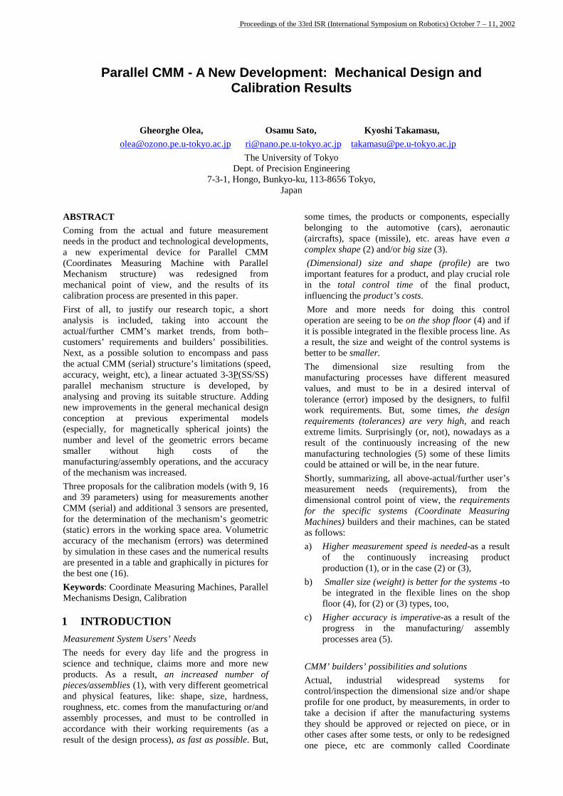
2.2 Actual system As is shown in the picture from Fig. 1, our actual new developed Parallel CMM - experimental system, contains generally, three important parts: Positioning Device (1), computer (2), driver-controller (3) and an auxiliary device (joystick) (4). In the following, a short (general) description and the
Fig.1 Parallel CMM system –
(1) (2)
(3)
(4) (P)
(WP)
general view
Proceedings of the 33rd ISR (International Symposium on Robotics) October 7 – 11, 2002
role for each component will be done sufficiently to understand how work the system as a whole. On 3DOF in translation (X, Y, Z) Parallel Mechanism -based the Positioning Device (1), moves with imposed speed, the probe (P)- ball tip (RENISHAW), and touches (with small force) the workpiece’s surface (WP). Every points (poses) along with the piece’s surface to be measured are computed (by the software) sending the Probe the output signals in the processing unit (computer/ controler (2)) in order to find the numerical value (dimensions) between the points, using the inverse kinematics model of the mechanism and by the sensors’ help. Details about it will be further disclosed(Chapter 3). In the computer system-DELL OptiPlex (2), the calculus and main data are exchanged between the sensors’ and motors’ states in order to compute the actual position of the probe and show on the display the usefully information about the dimensions of the measured piece. In its software (C++) the kinematics parameters determination is included, by solving the inverse/direct kinematics of the mechanism, in order to get the numerical measured value. It is a compatible personal computer (PC) with the main characteristics as follows: Processor-1.2GHz INTEL Pentium III, 256 SDRAM, 20 GB-hard drive. By using two PC board (HIVERTEC+ISA), the ties between computer and driver (controller) is maintaining with enough speed and reliability by the serial port. The Parallel CMM’s driver (Power Supply-NOGUCHI, 3 Intelligent Motor Amplifier-SANYO; 3 Condenser System set; Limit/Safety switches, etc) helps the user to drive the movement of the probe in accordance with the motors, software and sensor information. Electronic and electric parts are put together to control each of the three actuated axis (actuators), working as an interface between the physical Positioning Device and the computer or/and joystick by counted, convert and transmit analogue/digital signals. It controls all of the motion, safety, and human-machine interface functions. An additional very important device – the joystick (4) helps the users to easy move the probe, as a part between the human being and Parallel CMM physical system, in order to reduce the need for the user to address all the time the computer. It is made by some changes in a very common commercial joystick for games. As a result, the movement of the probe tip (mobile platform) may be accomplished manually or by the actuators’ servo drive, under the joystick control or computer program, as well-known. As the accuracy of measurement for one CMM system depends on precise correspondence between the probe tip (theoretical, ideal) position and the (real) position of the structure carrying the probe, during each mesurement cycle, the structure’s accuracy of positioning is from maximum importance, and mainly, are two ways (solutions) to improve it, beeing the main red-wire of this work: 1) Analysing and minimizing the physical system’s
movement total errror, by: a) increasing the accuracy of components, b) suitable conceptual
design – for the structure or technical solutions for manufacturing/assembly the components with acceptable level of errors and low price,
2) Calibrating it, by including (all) possible main errors in the calibration model for the mechanism.
Both solution, subject of this work, were taken in to acount in the (pre) design stage and after, and now they will be discused, in the following.
3 PARALLEL CMM - MECHANICAL DESIGN
In the above first solution for an improved accuracy of one mechanical structure (1), and especially for a CMM structure, second choice (b), the main step (even in the predesign stage) is to analyse and identify the number and/or type(level) of all posibile errors derived from the mechanism’s structure, during its work.These errors can be: static (geometric) and/or dynamic errors, external influences’ error, or others. Main sources of them are: a) the structure of the mechanism, b) the manufacturing/assembly processes, c) outside temperature, b) vibrations, etc. Not all are the same importance. But some of them can be taken in to the consideration even in the predesign stage to be skiping or reducing (minimaizing) their influences, by carefuly chosen design based on a deeply analysis of the existent solutions. Such reasons are for next paragraph topics.
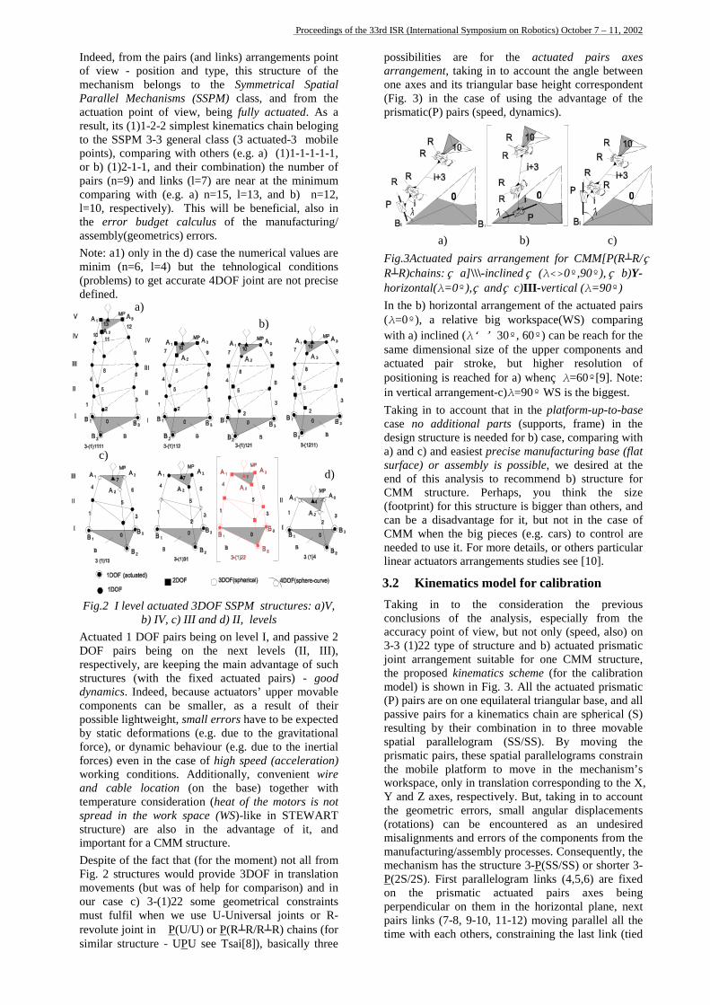
3.1 Structural conceptual design Even is already recognized from most of authors that the manufacturing/assembly errors for one mechanism play the most important role in the budget of the kinematics (geometric) errors with the influence on its accuracy, every specific arrangement of the joints and links, with the other words – its kinematics structure, can revealed others usefully information about the expected accuracy of the mechanism, and help the designers to choose a better structure from this point of view. But not only from this point of view; the analysis of structure can be usefully to understand if it is suitable or not to reach one level of the necessary speed, like in the CMM actual requirements, also(see Chapter 1). As is shown in Fig.2, from all the possible representation of the I level actuated 3DOF SSPM structures (see the SSPM explanation herein after), the actual fundamental structure of our Parallel CMM mechanism is c) 3-(1)22, and consist in three serial and identical spatial kinematics chains, having each of them, only three levels of joints (III), connecting the base (B) and the mobile platform (MP). Comparing with others, Fig. 2a, and/or Fig. 2b, where four and/or five levels (IV/V) can be seen, this could be an advantage, taking in to account the general number of the components (joints and/or links) or only the actuators’ upper movable part components (see next paragraphs for errors, also), with good results for the total manufacturing/assembly production costs (price of the mechanism) or its kinematics and dynamic characteristics.
Proceedings of the 33rd ISR (International Symposium on Robotics) October 7 – 11, 2002
Indeed, from the pairs (and links) arrangements point of view - position and type, this structure of the mechanism belongs to the Symmetrical Spatial Parallel Mechanisms (SSPM) class, and from the actuation point of view, being fully actuated. As a result, its (1)1-2-2 simplest kinematics chain beloging to the SSPM 3-3 general class (3 actuated-3 mobile points), comparing with others (e.g. a) (1)1-1-1-1-1, or b) (1)2-1-1, and their combination) the number of pairs (n=9) and links (l=7) are near at the minimum comparing with (e.g. a) n=15, l=13, and b) n=12, l=10, respectively). This will be beneficial, also in the error budget calculus of the manufacturing/ assembly(geometrics) errors. Note: a1) only in the d) case the numerical values are minim (n=6, l=4) but the tehnological conditions (problems) to get accurate 4DOF joint are not precise defined.
Fig.2 I level actuated 3DOF SSPM
b) IV, c) III and d) II, lActuated 1 DOF pairs being on leveDOF pairs being on the next respectively, are keeping the main astructures (with the fixed actuatedynamics. Indeed, because actuatorcomponents can be smaller, as apossible lightweight, small errors haby static deformations (e.g. due toforce), or dynamic behaviour (e.g. dforces) even in the case of high speworking conditions. Additionally, and cable location (on the basetemperature consideration (heat of spread in the work space (WS)-likstructure) are also in the advanimportant for a CMM structure. Despite of the fact that (for the momFig. 2 structures would provide 3Dmovements (but was of help for coour case c) 3-(1)22 some geomemust fulfil when we use U-Univerevolute joint in P(U/U) or P(R┴Rsimilar structure - UPU see Tsai[8]
possibilities are for the actuated pairs axes arrangement, taking in to account the angle between one axes and its triangular base height correspondent (Fig. 3) in the case of using the advantage of the prismatic(P) pairs (speed, dynamics).
a) b) c) Fig.3Actuated pairs arrangement for CMM[P(R┴R/ R┴R)chains: a]\\\-inclined (λ<>0º,90º), b)Y-horizontal(λ=0º), and c)III-vertical (λ=90º) In the b) horizontal arrangement of the actuated pairs (λ=0º), a relative big workspace(WS) comparing with a) inclined (λ<>30º, 60º) can be reach for the same dimensional size of the upper components and
b)
actuated pair stroke, but higher resolution of positioning is reached for a) when λ=60º[9]. Note: in vertical arrangement-c)λ=90º WS is the biggest. Taking in to account that in the platform-up-to-base case no additional parts (supports, frame) in the design structure is needed for b) case, comparing with a) and c) and easiest precise manufacturing base (flat surface) or assembly is possible, we desired at the
c)
structures: a)V, evels l I, and passive 2 levels (II, III), dvantage of such d pairs) - good s’ upper movable result of their ve to be expected the gravitational ue to the inertial ed (acceleration) convenient wire ) together with
the motors is not e in STEWART tage of it, and
ent) not all from OF in translation mparison) and in trical constraints rsal joints or R-/R┴R) chains (for ), basically three
end ofCMM (footprcan beCMM neededlinear a
3.2 Takingconcluaccura3-3 (1)joint athe promodel)(P) paipassiveresultinspatialprismathe mworkspY and the ge(rotatiomisaligmanufmechaP(2S/2on thperpenpairs ltime w
this analysis to recommend b) structure for
d)a)
structure. Perhaps, you think the size int) for this structure is bigger than others, and a disadvantage for it, but not in the case of when the big pieces (e.g. cars) to control are to use it. For more details, or others particular ctuators arrangements studies see [10].
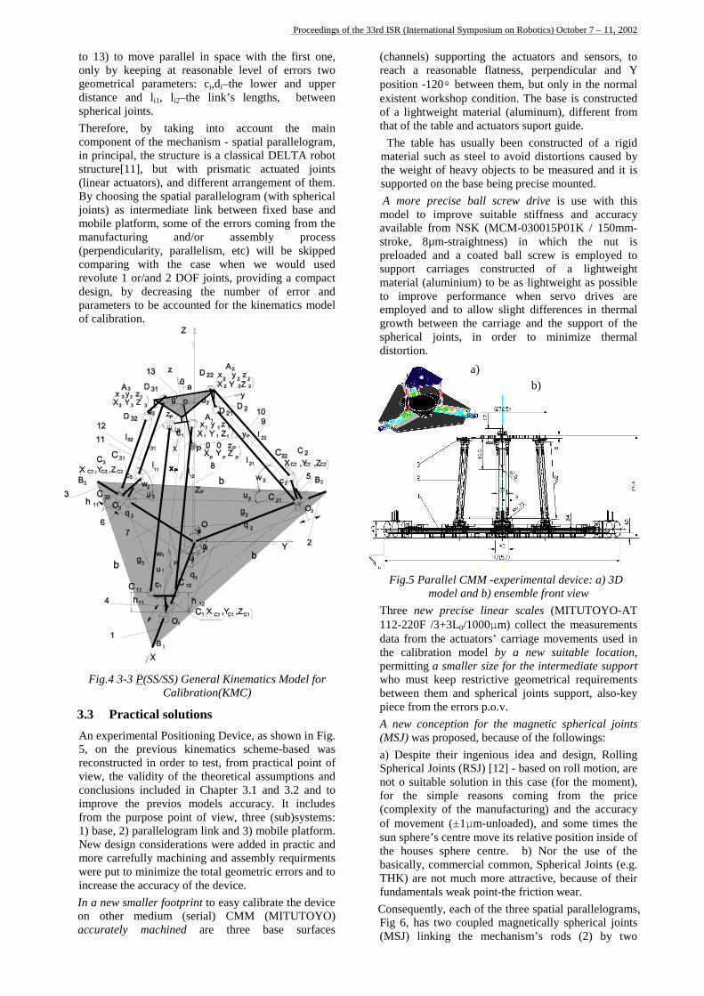
Kinematics model for calibration in to the consideration the previous sions of the analysis, especially from the cy point of view, but not only (speed, also) on 22 type of structure and b) actuated prismatic rrangement suitable for one CMM structure, posed kinematics scheme (for the calibration is shown in Fig. 3. All the actuated prismatic rs are on one equilateral triangular base, and all pairs for a kinematics chain are spherical (S) g by their combination in to three movable
parallelogram (SS/SS). By moving the tic pairs, these spatial parallelograms constrain obile platform to move in the mechanism’s ace, only in translation corresponding to the X, Z axes, respectively. But, taking in to account ometric errors, small angular displacements ns) can be encountered as an undesired nments and errors of the components from the
acturing/assembly processes. Consequently, the nism has the structure 3-P(SS/SS) or shorter 3-S). First parallelogram links (4,5,6) are fixed e prismatic actuated pairs axes being dicular on them in the horizontal plane, next inks (7-8, 9-10, 11-12) moving parallel all the ith each others, constraining the last link (tied
Proceedings of the 33rd ISR (International Symposium on Robotics) October 7 – 11, 2002
to 13) to move parallel in space with the first one, only by keeping at reasonable level of errors two geometrical parameters: ci,di–the lower and upper distance and li1, li2–the link’s lengths, between spherical joints. Therefore, by taking into account the main component of the mechanism - spatial parallelogram, in principal, the structure is a classical DELTA robot structure[11], but with prismatic actuated joints (linear actuators), and different arrangement of them. By choosing the spatial parallelogram (with spherical joints) as intermediate link between fixed base and mobile platform, some of the errors coming from the manufacturing and/or assembly process (perpendicularity, parallelism, etc) will be skipped comparing with the case when we would used revolute 1 or/and 2 DOF joints, providing a compact design, by decreasing the number of error and parameters to be accounted for the kinematics model of calibration.
Fig.4 3-3 P(SS/SS) General Kinematics Model for Calibration(KMC)
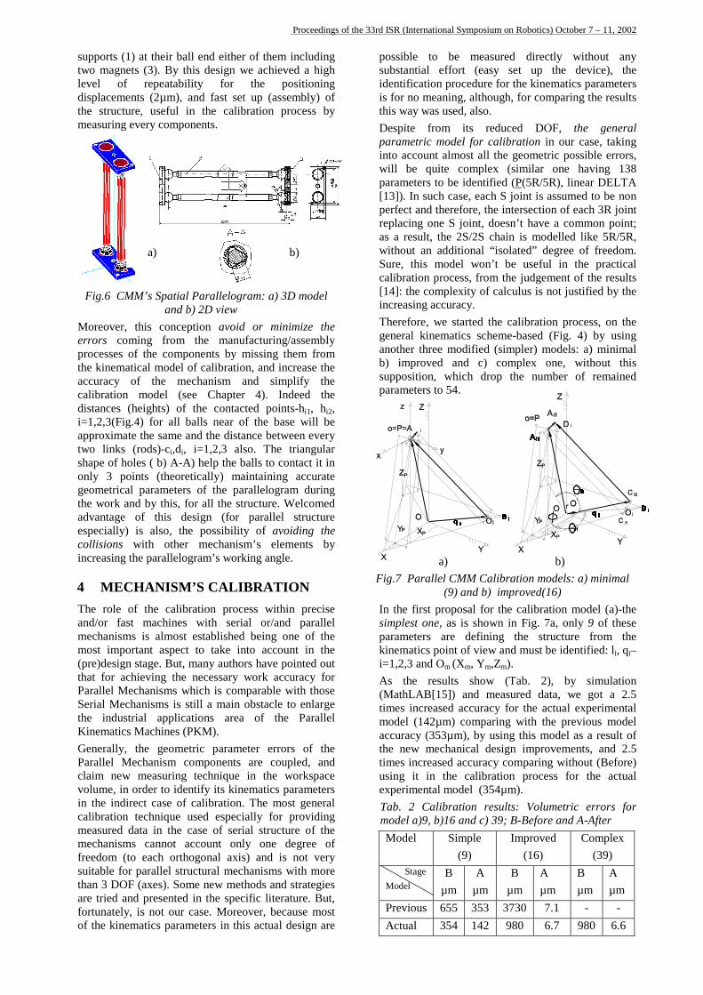
3.3 Practical solutions An experimental Positioning Device, as shown in Fig. 5, on the previous kinematics scheme-based was reconstructed in order to test, from practical point of view, the validity of the theoretical assumptions and conclusions included in Chapter 3.1 and 3.2 and to improve the previos models accuracy. It includes from the purpose point of view, three (sub)systems: 1) base, 2) parallelogram link and 3) mobile platform. New design considerations were added in practic and more carrefully machining and assembly requirments were put to minimize the total geometric errors and to increase the accuracy of the device. In a new smaller footprint to easy calibrate the device on other medium (serial) CMM (MITUTOYO) accurately machined are three base surfaces
(channels) supporting the actuators and sensors, to reach a reasonable flatness, perpendicular and Y position -120º between them, but only in the normal existent workshop condition. The base is constructed of a lightweight material (aluminum), different from that of the table and actuators suport guide. The table has usually been constructed of a rigid material such as steel to avoid distortions caused by the weight of heavy objects to be measured and it is supported on the base being precise mounted. A more precise ball screw drive is use with this model to improve suitable stiffness and accuracy available from NSK (MCM-030015P01K / 150mm-stroke, 8µm-straightness) in which the nut is preloaded and a coated ball screw is employed to support carriages constructed of a lightweight material (aluminium) to be as lightweight as possible to improve performance when servo drives are employed and to allow slight differences in thermal growth between the carriage and the support of the spherical joints, in order to minimize thermal distortion.
Fig.5 Parallel CMM -experimmodel and b) ensemb
Three new precise linear sc112-220F /3+3L0/1000µm) codata from the actuators’ carriathe calibration model by a permitting a smaller size for thwho must keep restrictive gebetween them and spherical jpiece from the errors p.o.v. A new conception for the ma(MSJ) was proposed, because oa) Despite their ingenious ideSpherical Joints (RSJ) [12] - bnot o suitable solution in this for the simple reasons com(complexity of the manufactuof movement (±1µm-unloadedsun sphere’s centre move its rethe houses sphere centre. bbasically, commercial commonTHK) are not much more attrfundamentals weak point-the fr
Consequently, each of the threeFig 6, has two coupled magn(MSJ) linking the mechanis
b)
a)ental device: a) 3D le front view
ales (MITUTOYO-AT llect the measurements ge movements used in new suitable location, e intermediate support
ometrical requirements oints support, also-key
gnetic spherical joints f the followings: a and design, Rolling
ased on roll motion, are case (for the moment),
ing from the price ring) and the accuracy ), and some times the
lative position inside of ) Nor the use of the , Spherical Joints (e.g.
active, because of their iction wear. spatial parallelograms,
etically spherical joints m’s rods (2) by two
Proceedings of the 33rd ISR (International Symposium on Robotics) October 7 – 11, 2002
supports (1) at their ball end either of them including two magnets (3). By this design we achieved a high level of repeatability for the positioning displacements (2µm), and fast set up (assembly) of the structure, useful in the calibration process by measuring every components.
Fig.6 CMM’s Spatial Parallelogram: a) 3
and b) 2D view Moreover, this conception avoid or minerrors coming from the manufacturingprocesses of the components by missing the kinematical model of calibration, and inaccuracy of the mechanism and simcalibration model (see Chapter 4). Indistances (heights) of the contacted poini=1,2,3(Fig.4) for all balls near of the baapproximate the same and the distance betwtwo links (rods)-ci,di, i=1,2,3 also. The shape of holes ( b) A-A) help the balls to conly 3 points (theoretically) maintaininggeometrical parameters of the parallelogrthe work and by this, for all the structure. advantage of this design (for parallelespecially) is also, the possibility of avcollisions with other mechanism’s eleincreasing the parallelogram’s working angl
4 MECHANISM’S CALIBRATThe role of the calibration process withand/or fast machines with serial or/anmechanisms is almost established being omost important aspect to take into acco(pre)design stage. But, many authors have pthat for achieving the necessary work acParallel Mechanisms which is comparable Serial Mechanisms is still a main obstaclethe industrial applications area of thKinematics Machines (PKM). Generally, the geometric parameter erroParallel Mechanism components are couclaim new measuring technique in the volume, in order to identify its kinematics in the indirect case of calibration. The mocalibration technique used especially formeasured data in the case of serial structmechanisms cannot account only one freedom (to each orthogonal axis) and issuitable for parallel structural mechanisms than 3 DOF (axes). Some new methods andare tried and presented in the specific literfortunately, is not our case. Moreover, becof the kinematics parameters in this actual
possible to be measured directly without any substantial effort (easy set up the device), the identification procedure for the kinematics parameters is for no meaning, although, for comparing the results this way was used, also. Despite from its reduced DOF, the general parametric model for calibration in our case, taking into account almost all the geometric possible errors, will be quite complex (similar one having 138 parameters to be identified (P(5R/5R), linear DELTA [13]). In such case, each S joint is assumed to be non perfect and therefore, the intersection of each 3R joint replacing one S joint, doesn’t have a common point; as a result, the 2S/2S chain is modelled like 5R/5R, without an additional “isolated” degree of freedom.
b) a)D model
imize the /assembly
them from crease the plify the deed the ts-hi1, hi2, se will be een every triangular
ontact it in accurate
am during Welcomed structure oiding the ments by e.
ION in precise d parallel ne of the
unt in the ointed out
curacy for with those to enlarge e Parallel
rs of the pled, and workspace parameters st general
providing ure of the degree of not very with more strategies ature. But, ause most design are
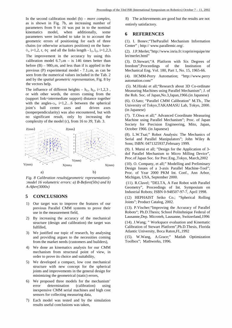
Sure, this model won’t be useful in the practical calibration process, from the judgement of the results [14]: the complexity of calculus is not justified by the increasing accuracy. Therefore, we started the calibration process, on the general kinematics scheme-based (Fig. 4) by using another three modified (simpler) models: a) minimal b) improved and c) complex one, without this supposition, which drop the number of remained parameters to 54. a) b)
Fig.7 Parallel CMM Calibration models: a) minimal (9) and b) improved(16)
In the first proposal for the calibration model (a)-the simplest one, as is shown in Fig. 7a, only 9 of these parameters are defining the structure from the kinematics point of view and must be identified: li, qi– i=1,2,3 and Om (Xm, Ym,Zm). As the results show (Tab. 2), by simulation (MathLAB[15]) and measured data, we got a 2.5 times increased accuracy for the actual experimental model (142µm) comparing with the previous model accuracy (353µm), by using this model as a result of the new mechanical design improvements, and 2.5 times increased accuracy comparing without (Before) using it in the calibration process for the actual experimental model (354µm). Tab. 2 Calibration results: Volumetric errors for model a)9, b)16 and c) 39; B-Before and A-After Model Simple
(9) Improved
(16) Complex
(39) StageModel
B µm
A µm
B µm
A µm
B µm
A µm
Previous 655 353 3730 7.1 - - Actual 354 142 980 6.7 980 6.6
Proceedings of the 33rd ISR (International Symposium on Robotics) October 7 – 11, 2002
In the second calibration model (b) – more complex, as is shown in Fig. 7b, an increasing number of parameters from 9 to 16 was put in to the nominal kinematics model, when additionally, some parameters were included to take in to account the geometric errors of positioning for each of three chains (or otherwise actuators positions) on the base-θi, i=1,2, r, Φ and all the links length - li1, li2, i=1,2,3. The improvement in the accuracy by using this calibration model 6.7µm – is 146 times better than before (B) – 980µm, and less than if is applied in the previous (P) experimental model - 7.1µm, as can be seen from the numerical values included in the Tab. 2 and by the spatial geometric representation, Fig. 8 by the vectors help. The influence of different heights – hi1, hi2, i=1,2,3 , or with other words, the errors coming from the (support link+intermediate support) distance together with the angles-αi, i=1,2…6 between the spherical joint’s ball centre axes and driven axes (nonperpendicularity) was also encountered, but with no significant result, only by increasing the complexity of the model (c), from 16 to 39, Tab. 3.
a)
Fig. 8 Calibration res:model 16 volumetric A-After(3000x)
5 CONCLUSIO1) Our target was t
previous Paralleluse in the measure
2) By increasing thstructure (design fulfilled,
3) We justified our and providing arfrom the market n
4) We done an kinemechanism fromorder to prove its
5) We developed a structure with njoints and improvminimizing the ge
6) We proposed threrror determininexpensive CMMsensors for collec
7) Each model wasresults useful con
8) The achievements are good but the results are not entirely satisfactory.
6 REFERENCES (1). I. Bonev;“TheParallel Mechanism Information Center” ; http:// www.parallemic.org/. (2). J.P.Merlet;”http://www.inria.fr:/coprin/equipe/mr let/merlet.html” (3). D.Stewart;“A Platform with Six Degrees of freedom”;Proceedings of the Institution of Mechanical Eng. Vol. 180, Part 1, No. 15, 1965-66. (4). HCMM-Perry Automation; “http://www.perry automation.com/” (5). M.Hiraki et all;“Research about 3D Co-ordinate Measuring Machines using Parallel Mechanism”; J. of the Rob. Soc. of Japan,No.3,Japan,1966.(in Japanese) (6). O.Sato; “Parallel CMM Calibration” M.Th., The University of Tokyo,TAKAMASU Lab, Tokyo, 2000. (in Japanese) (7). T.Oiwa et all;” Advanced Coordinate Measuring Machine using Parallel Mechanism”; Proc. of Japan Society for Precision Engineering, Mito, Japan, October 1966. (in Japanese) (8). L.W.Tsai;” Robot Analysis: The Mechanics of Serial and Parallel Manipulators”; John Wiley & Sons; ISBN: 0471325937,February 1999. (9). I. Murui et all; ”Design for the Application of 3-dof Parallel Mechanism to Micro Milling Device”, Proc.of Japan Soc. for Prec.Eng.,Tokyo, March,2002 (10). O. Company, et all;” Modelling and Preliminary Design Issues of a 3-axis Parallel Machine-Tool”;
X(mm)
X(mm)Y(mm)
Z(mm)
uer
No Cme an
togueem schcoewemomeeat
tin tclu
Z(mm)
lts(grors
S impMMent accd c
pic es tds (atictrucoicemp coentetr
moion seriag mestesion
Y(mm)
b) eometric representation)-: a) B-Before(50x) and b)
rove the features of our systems to prove their
field, uracy of the mechanical alibration) the target was
of research, by analysing o the necessities coming customers and builders), s analysis for our CMM tural point of view, in and suitability,
act, low cost mechanical ncept for the spherical
s in the general design for ical (static) errors, dels for the mechanism’
(calibration) using l machines and high cost easuring data, d and by the simulation s was taken,
Proc. of Year 2000 PKM Int. Conf., Ann Arbor, Michigan, USA, September 2000. (11). R.Clavel; ”DELTA, A Fast Robot with Parallel Geometry”, Proceedings of Int. Symposium on Industrial Robots; ISBN 0-948507-97-7, April 1998. (12) HEPHAIST Seiko Co.; “Spherical Rolling Joints”; Product Catalog, 2002. (13). P.Vischer;“Improving the Accuracy of Parallel Robots“; Ph.D.Thesis; School Politehnique Federal of Lausanne,Dep. Microteh, Lausanne, Switzerland,1996 (14). J.Wang; ” Workspace evaluation and Kinematic Calibration of Stewart Platform”,Ph.D.Thesis, Florida Atlantic University, Boca Raton,FL,1992 (15). W.Wang, A.Grace;” Matlab Optimization Toolbox”; Mathworks, 1996.

Proceedings of the 33rd ISR (International Symposium on Robotics) October 7 – 11, 2002