par ts manual service manual - manuals - geniemanuals.gogenielift.com/parts and service...
TRANSCRIPT
Parts Manual
Serial Number Range
Service Manual
Part No. 65248
Rev D
June 2007
Serial Number Range
GS-2668 DC from introduction
GS-3268 DC from introduction
June 2007
GS-2668 DC • GS-3268 DC Part No. 65248ii
Introduction
Important
Read, understand and obey the safety rules andoperating instructions in the Genie GS-2668 DC andGS-3268 DC Operator's Manual before attemptingany maintenance or repair procedure.
This manual provides detailed scheduledmaintenance information for the machine ownerand user. It also provides troubleshooting andrepair procedures for qualified serviceprofessionals.
Basic mechanical, hydraulic and electricalskills are required to perform most procedures.However, several procedures require specializedskills, tools, lifting equipment and a suitableworkshop. In these instances, we stronglyrecommend that maintenance and repair beperformed at an authorized Genie dealerservice center.
Technical Publications
Genie Industries has endeavored to deliver thehighest degree of accuracy possible. However,continuous improvement of our products is a Geniepolicy. Therefore, product specificationsare subject to change without notice.
Readers are encouraged to notify Genie of errorsand send in suggestions for improvement. Allcommunications will be carefully considered forfuture printings of this and all other manuals.
Contact Us:
PO Box 97030Redmond, WA 98073-9730 USA
www.genieindustries.come-mail: [email protected]
Copyright © 1999 by Genie Industries
65248 Rev D June 2007First Edition, Fourth Printing
"Genie" is a registered trademark of GenieIndustries in the USA and many other countries."GS" is a trademark of Genie Industries.
Printed on recycled paper
Printed in U.S.A.
Introduction

June 2007
Part No. 65248 GS-2668 DC • GS-3268 DC
Serial Number Legend
iii
INTRODUCTION
GS68 06 A - 12345
Model
Year ofmanufacture
Facility code(if applicable)
Sequencenumber
PN - 77055
Model:
Model year: Manufacture date:
Maximum allowable inclination of the chassis:
Country of manufacture: USA
This machine complies with:
Serial number:
Rated work load (including occupants):
Genie Industries
18340 NE 76th Street
Redmond, WA 98052
USA
Electrical schematic number:
Gradeability:
Maximum allowable side force :
Maximum number of platform occupants:
Machine unladen weight:
ANSI A92.6-1999B354.2-01
GS-3268 DC
GS6806-12345
04/12/06
Es7150
8,010 lb / 3,633 kg
1000 lb / 454 kg
N/A
N/A
200 lb / 90 N
4
2005
Serial number(stamped on chassis)
Serial label(located under cover)
June 2007
GS-2668 DC • GS-3268 DC Part No. 65248
This page intentionally left blank.
iv

June 2007
Part No. 65248 GS-2668 DC • GS-3268 DC
Safety Rules
Section 1 • Safety Rules
DangerFailure to obey the instructions and safety rulesin this manual and the Genie GS-2668 DC andGS-3268 DC Operator's Manual will result in deathor serious injury.
Many of the hazards identified in theoperator’s manual are also safety hazardswhen maintenance and repair proceduresare performed.
Do Not Perform MaintenanceUnless:
You are trained and qualified to performmaintenance on this machine.
You read, understand and obey:- manufacturer’s instructions and safety rules- employer’s safety rules and worksite
regulations- applicable governmental regulations
You have the appropriate tools, liftingequipment and a suitable workshop.
v
June 2007
GS-2668 DC • GS-3268 DC Part No. 65248
Section 1 • Safety Rules
vi
Personal SafetyAny person working on or around a machine mustbe aware of all known safety hazards. Personalsafety and the continued safe operation of themachine should be your top priority.
Read each procedure thoroughly. Thismanual and the decals on the machine,use signal words to identify the following:
Safety alert symbol—used to alertpersonnel to potential personalinjury hazards. Obey all safetymessages that follow this symbolto avoid possible injury or death.
Indicates an imminently hazardoussituation which, if not avoided, willresult in death or serious injury.
Indicates a potentially hazardoussituation which, if not avoided,could result in death or seriousinjury.
Indicates a potentially hazardoussituation which, if not avoided,may cause minor or moderateinjury.
Indicates a potentially hazardoussituation which, if not avoided,may result in property damage.
Be sure to wear protective eye wear andother protective clothing if the situationwarrants it.
Be aware of potential crushing hazardssuch as moving parts, free swinging orunsecured components when lifting or
placing loads. Always wear approved steel-toedshoes.
Workplace SafetyBe sure to keep sparks, flames andlighted tobacco away from flammable andcombustible materials like battery gases
and engine fuels. Always have an approved fireextinguisher within easy reach.
Be sure that all tools and working areasare properly maintained and ready for use.Keep work surfaces clean and free of
debris that could get into machine components andcause damage.
Be sure any forklift, overhead crane orother lifting or supporting device is fullycapable of supporting and stabilizing the
weight to be lifted. Use only chains or straps thatare in good condition and of ample capacity.
Be sure that fasteners intended for onetime use (i.e., cotter pins and self-lockingnuts) are not reused. These components
may fail if they are used a second time.
Be sure to properly dispose of old oil orother fluids. Use an approved container.Please be environmentally safe.
Be sure that your workshop or work area isproperly ventilated and well lit.
SAFETY RULES
June 2007
Part No. 65248 GS-2668 DC • GS-3268 DC
Table of Contents
Introduction
Important Information ......................................................................................... ii
Serial Number Legend ....................................................................................... iii
Section 1 Safety Rules
General Safety Rules ........................................................................................ v
Section 2 Rev Specifications
D Machine Specifications ................................................................................ 2 - 1
Performance Specifications ......................................................................... 2 - 2
Hydraulic Specifications ............................................................................... 2 - 3
Hydraulic Component Specifications ............................................................ 2 - 4
Manifold Component Specifications ............................................................. 2 - 5
Valve Coil Resistance Specifications ........................................................... 2 - 5
Hydraulic Hose and Fitting Torque Specifications......................................... 2 - 6
SAE and Metric Fasteners Torque Charts .................................................... 2 - 8
Section 3 Rev Scheduled Maintenance Procedures
Introduction .................................................................................................. 3 - 1
Pre-delivery Preparation Report .................................................................... 3 - 3
Maintenance Inspection Report .................................................................... 3 - 5
E Checklist A Procedures
A-1 Inspect the Manuals and Decals ......................................................... 3 - 6
A-2 Perform Pre-operation Inspection ........................................................ 3 - 7
A-3 Perform Function Tests ...................................................................... 3 - 7
A-4 Perform 30 Day Service ...................................................................... 3 - 7
vii
June 2007
GS-2668 DC • GS-3268 DC Part No. 65248
TABLE OF CONTENTS
Section 3 Rev Scheduled Maintenance Procedures, continued
F Checklist B Procedures
B-1 Inspect the Batteries ........................................................................... 3 - 8
B-2 Inspect the Electrical Wiring ............................................................. 3 - 10
B-3 Inspect the Tires, Wheels and Castle Nut Torque ............................. 3 - 11
B-4 Test the Emergency Stop ................................................................. 3 - 11
B-5 Test the Key Switch ......................................................................... 3 - 12
B-6 Test the Automotive Style Horn (if equipped) .................................... 3 - 12
B-7 Test the Drive Brakes ....................................................................... 3 - 13
B-8 Test the Drive Speed - Stowed Position ............................................ 3 - 13
B-9 Test the Drive Speed - Raised Position ............................................. 3 - 14
B-10 Check the Module Tray Latch Components ....................................... 3 - 14
B-11 Perform Hydraulic Oil Analysis ......................................................... 3 - 15
A Checklist C Procedure
C-1 Test the Platform Overload System (if equipped) .............................. 3 - 16
D Checklist D Procedures
D-1 Check the Scissor Arm Wear Pads ................................................. 3 - 18
D-2 Replace the Hydraulic Tank Return Filter ......................................... 3 - 19
C Checklist E Procedures
E-1 Test or Replace the Hydraulic Oil ...................................................... 3 - 20
E-2 Grease the Steer Axle Wheel Bearings ............................................. 3 - 22
viii
June 2007
Part No. 65248 GS-2668 DC • GS-3268 DC
TABLE OF CONTENTS
Section 4 Rev Repair Procedures
Introduction .................................................................................................. 4 - 1
E Platform Controls
1-1 Circuit Boards ..................................................................................... 4 - 2
1-2 Joystick Controller .............................................................................. 4 - 3
1-3 Controller Adjustments ....................................................................... 4 - 5
1-4 Software Configuration(before serial number GS6805-44699) ............................................... 4 - 13
1-5 Software Configuration(after serial number GS6805-44698) .................................................. 4 - 18
1-6 Toggle Switches .................................................................................4 -22
B Platform Components
2-1 Platform............................................................................................ 4 - 23
2-2 Platform Extension ........................................................................... 4 - 24
B Scissor Components
3-1 Scissor Assembly, GS-2668 DC....................................................... 4 - 26
3-2 Scissor Assembly, GS-3268 DC....................................................... 4 - 34
3-3 Lift Cylinder ...................................................................................... 4 - 41
3-4 Platform Overload System (if equipped) ........................................... 4 - 44
C Ground Controls
4-1 Manual Platform Lowering ................................................................. 4 - 49
4-2 Toggle Switches ............................................................................... 4 - 50
4-3 Control Relays .................................................................................. 4 - 51
4-4 Tilt Level Sensor .............................................................................. 4 - 52
ix
June 2007
GS-2668 DC • GS-3268 DC Part No. 65248
TABLE OF CONTENTS
Section 4 Rev Repair Procedures, continued
B Hydraulic Pump
5-1 Function Pump ................................................................................. 4 - 59
C Function Manifold
6-1 Function Manifold Components(before serial number 40594) ............................................................. 4 - 62
6-2 Function Manifold Components(from serial number 40594 to 41199) ................................................. 4 - 64
6-3 Function Manifold Components(after serial number 41199) ............................................................... 4 - 68
6-4 Valve Adjustments - Function Manifold ............................................ 4 - 70
6-5 Valve Coils ....................................................................................... 4 - 76
B Hydraulic Tank
7-1 Hydraulic Tank ................................................................................. 4 - 78
C Steer Axle Components
8-1 Yoke and Drive Motor ....................................................................... 4 - 80
8-2 Yoke and Spindle ............................................................................. 4 - 83
8-3 Steer Cylinder ................................................................................... 4 - 85
8-4 Tie Rod ............................................................................................. 4 - 86
C Non-steer Axle Components
9-1 Brake Motor ...................................................................................... 4 - 87
9-2 Drive/Brake Motor ............................................................................. 4 - 88
C Brake Release Hand Pump Components
10-1 Brake Release Hand Pump Components .......................................... 4 - 89
x

June 2007
Part No. 65248 GS-2668 DC • GS-3268 DC
TABLE OF CONTENTS
Section 5 Rev Troubleshooting Flow Charts and Fault Codes
Introduction .................................................................................................. 5 - 1
C Fault Code Chart(before serial number 41200) ........................................................................ 5 - 3
C Fault Code Chart(from serial number 41200 to GS6805-44698) ............................................... 5 - 7
A Fault Code Chart(after serial number GS6805-44698) ............................................................. 5 - 8
ChartNumber Chart Title
1 D All Functions Will Not Operate(before serial number 41200) ........................................................................ 5 - 9
1A C All Functions Will Not Operate(after serial number 41199) ......................................................................... 5 - 11
2 D Pump Motor Will Not Operate(before serial number 41200) ...................................................................... 5 - 13
2A C Pump Motor Will Not Operate(after serial number 41199) ......................................................................... 5 - 14
3 D All Functions Inoperative, Power Unit Starts and Runs(before serial number 41200) ...................................................................... 5 - 16
3A C All Functions Inoperative, Power Unit Starts and Runs(after serial number 41199) ......................................................................... 5 - 17
4 D Ground Controls Inoperative, Platform Controls Operate Normally(before serial number 41200) ...................................................................... 5 - 18
4A C Ground Controls Inoperative, Platform Controls Operate Normally(after serial number 41199) ......................................................................... 5 - 19
5 D Platform Controls Inoperative, Ground Controls Operate Normally(before serial number 41200) ...................................................................... 5 - 20
5A C Platform Controls Inoperative, Ground Controls Operate Normally(after serial number 41199) ......................................................................... 5 - 21
6 D Platform Up Function Inoperative(before serial number 41200) ...................................................................... 5 - 22
6A C Platform Up Function Inoperative(after serial number 41199) ......................................................................... 5 - 23
xi

June 2007
GS-2668 DC • GS-3268 DC Part No. 65248
TABLE OF CONTENTS
Section 5 Rev Troubleshooting Flow Charts and Fault Codes, continued
7 D Platform Down Function Inoperative, GS-2668 DC(before serial number 41200) ...................................................................... 5 - 24
8 D Platform Down Function Inoperative, GS-2668 DC(after serial number 41199) and GS-3268 (all) ............................................. 5 - 25
9 D Steer Left Function Inoperative(before serial number 41200) ...................................................................... 5 - 27
9A C Steer Left Function Inoperative(after serial number 41199) ......................................................................... 5 - 28
10 D Steer Right Function Inoperative(before serial number 41200) ...................................................................... 5 - 30
10A C Steer Right Function Inoperative(after serial number 41199) ......................................................................... 5 - 31
11 D All Drive Functions Inoperative, All Other Functions Operate Normally(before serial number 41200) ...................................................................... 5 - 33
11A C All Drive Functions Inoperative, All Other Functions Operate Normally(after serial number 41199) ......................................................................... 5 - 34
12 D Brake Release Function Inoperative(before serial number 41200) ...................................................................... 5 - 35
12A C Brake Release Function Inoperative(after serial number 41199) ......................................................................... 5 - 36
13 D Drive Forward Function Inoperative(before serial number 41200) ...................................................................... 5 - 37
13A C Drive Forward Function Inoperative(after serial number 41199) ......................................................................... 5 - 38
14 D Drive Reverse Function Inoperative(before serial number 41200) ...................................................................... 5 - 39
14A C Drive Reverse Function Inoperative(after serial number 41199) ......................................................................... 5 - 40
xii
June 2007
Part No. 65248 GS-2668 DC • GS-3268 DC
TABLE OF CONTENTS
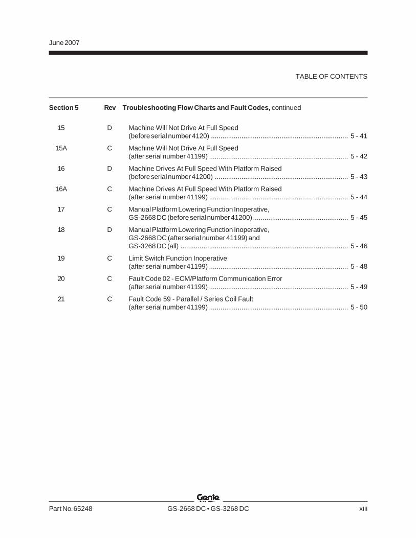
Section 5 Rev Troubleshooting Flow Charts and Fault Codes, continued
15 D Machine Will Not Drive At Full Speed(before serial number 4120) ........................................................................ 5 - 41
15A C Machine Will Not Drive At Full Speed(after serial number 41199) ......................................................................... 5 - 42
16 D Machine Drives At Full Speed With Platform Raised(before serial number 41200) ...................................................................... 5 - 43
16A C Machine Drives At Full Speed With Platform Raised(after serial number 41199) ......................................................................... 5 - 44
17 C Manual Platform Lowering Function Inoperative,GS-2668 DC (before serial number 41200) .................................................. 5 - 45
18 D Manual Platform Lowering Function Inoperative,GS-2668 DC (after serial number 41199) andGS-3268 DC (all) ........................................................................................ 5 - 46
19 C Limit Switch Function Inoperative(after serial number 41199) ......................................................................... 5 - 48
20 C Fault Code 02 - ECM/Platform Communication Error(after serial number 41199) ......................................................................... 5 - 49
21 C Fault Code 59 - Parallel / Series Coil Fault(after serial number 41199) ......................................................................... 5 - 50
xiii
June 2007
GS-2668 DC • GS-3268 DC Part No. 65248
TABLE OF CONTENTS
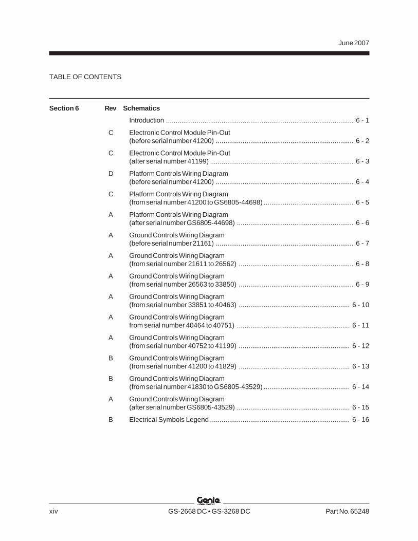
Section 6 Rev Schematics
Introduction .................................................................................................. 6 - 1
C Electronic Control Module Pin-Out(before serial number 41200) ........................................................................ 6 - 2
C Electronic Control Module Pin-Out(after serial number 41199) ........................................................................... 6 - 3
D Platform Controls Wiring Diagram(before serial number 41200) ........................................................................ 6 - 4
C Platform Controls Wiring Diagram(from serial number 41200 to GS6805-44698) ............................................... 6 - 5
A Platform Controls Wiring Diagram(after serial number GS6805-44698) ............................................................. 6 - 6
A Ground Controls Wiring Diagram(before serial number 21161) ........................................................................ 6 - 7
A Ground Controls Wiring Diagram(from serial number 21611 to 26562) ............................................................ 6 - 8
A Ground Controls Wiring Diagram(from serial number 26563 to 33850) ............................................................ 6 - 9
A Ground Controls Wiring Diagram(from serial number 33851 to 40463) .......................................................... 6 - 10
A Ground Controls Wiring Diagramfrom serial number 40464 to 40751) ........................................................... 6 - 11
A Ground Controls Wiring Diagram(from serial number 40752 to 41199) .......................................................... 6 - 12
B Ground Controls Wiring Diagram(from serial number 41200 to 41829) .......................................................... 6 - 13
B Ground Controls Wiring Diagram(from serial number 41830 to GS6805-43529) ............................................. 6 - 14
A Ground Controls Wiring Diagram(after serial number GS6805-43529) ........................................................... 6 - 15
B Electrical Symbols Legend ......................................................................... 6 - 16
xiv
June 2007
Part No. 65248 GS-2668 DC • GS-3268 DC
TABLE OF CONTENTS
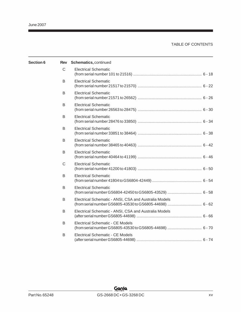
Section 6 Rev Schematics, continued
C Electrical Schematic(from serial number 101 to 21516) .............................................................. 6 - 18
B Electrical Schematic(from serial number 21517 to 21570) .......................................................... 6 - 22
B Electrical Schematic(from serial number 21571 to 26562) .......................................................... 6 - 26
B Electrical Schematic(from serial number 26563 to 28475) .......................................................... 6 - 30
B Electrical Schematic(from serial number 28476 to 33850) .......................................................... 6 - 34
B Electrical Schematic(from serial number 33851 to 38464) .......................................................... 6 - 38
B Electrical Schematic(from serial number 38465 to 40463) .......................................................... 6 - 42
B Electrical Schematic(from serial number 40464 to 41199) .......................................................... 6 - 46
C Electrical Schematic(from serial number 41200 to 41803) .......................................................... 6 - 50
B Electrical Schematic(from serial number 41804 to GS6804-42449) ............................................. 6 - 54
B Electrical Schematic(from serial number GS6804-42450 to GS6805-43529) ............................... 6 - 58
B Electrical Schematic - ANSI, CSA and Australia Models(from serial number GS6805-43530 to GS6805-44698) ............................... 6 - 62
B Electrical Schematic - ANSI, CSA and Australia Models(after serial number GS6805-44698) ........................................................... 6 - 66
B Electrical Schematic - CE Models(from serial number GS6805-43530 to GS6805-44698) ............................... 6 - 70
B Electrical Schematic - CE Models(after serial number GS6805-44698) ........................................................... 6 - 74
xv
June 2007
GS-2668 DC • GS-3268 DC Part No. 65248
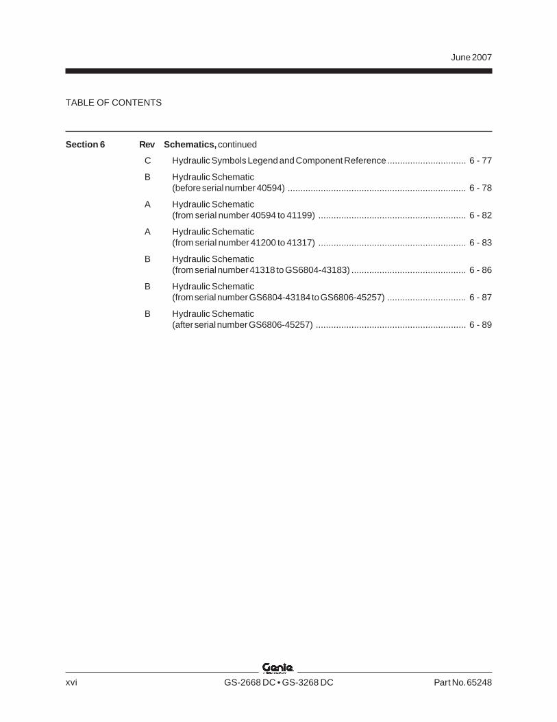
Section 6 Rev Schematics, continued
C Hydraulic Symbols Legend and Component Reference............................... 6 - 77
B Hydraulic Schematic(before serial number 40594) ...................................................................... 6 - 78
A Hydraulic Schematic(from serial number 40594 to 41199) .......................................................... 6 - 82
A Hydraulic Schematic(from serial number 41200 to 41317) .......................................................... 6 - 83
B Hydraulic Schematic(from serial number 41318 to GS6804-43183) ............................................. 6 - 86
B Hydraulic Schematic(from serial number GS6804-43184 to GS6806-45257) ............................... 6 - 87
B Hydraulic Schematic(after serial number GS6806-45257) ........................................................... 6 - 89
xvi
TABLE OF CONTENTS
REV D
Section 2 • SpecificationsJune 2007
Part No. 65248 GS-2668 DC • GS-3268 DC 2 - 1
Specifications
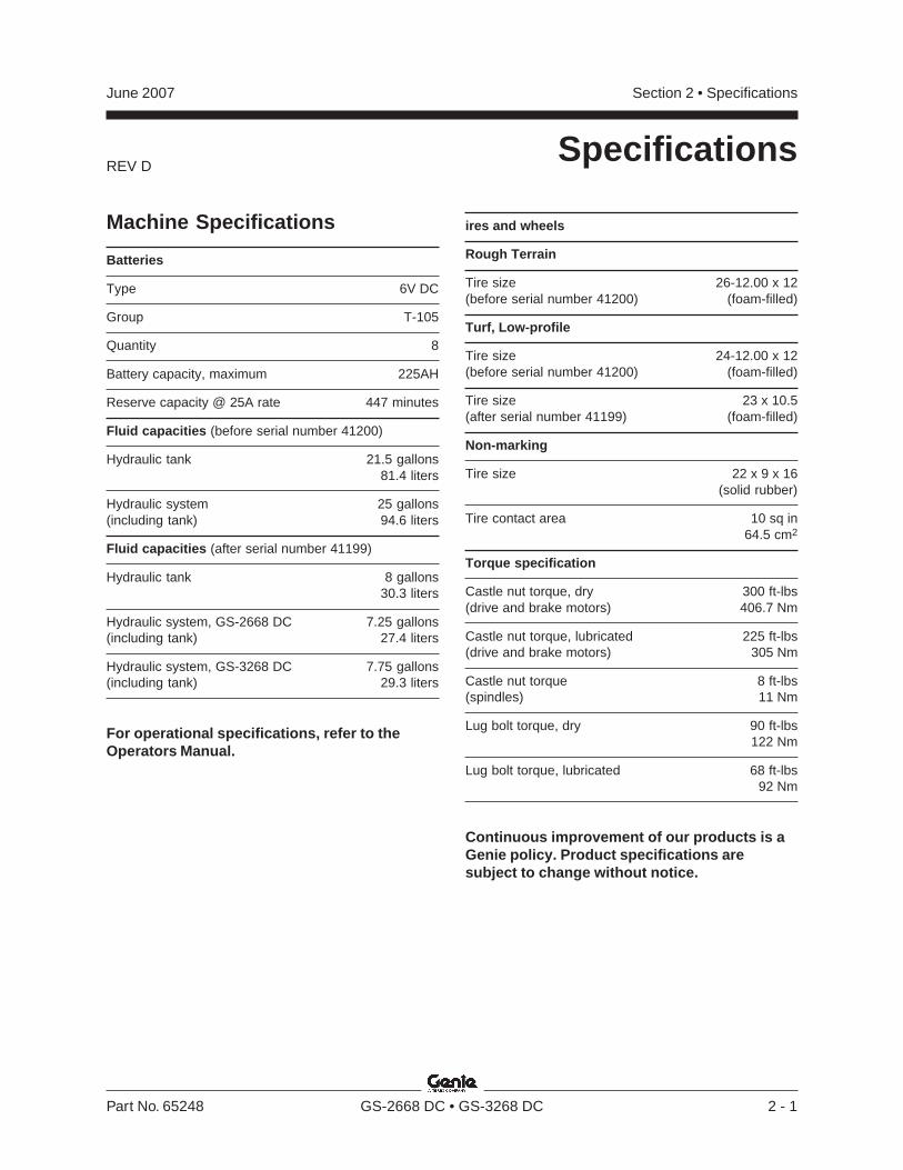
Machine Specifications
Batteries
Type 6V DC
Group T-105
Quantity 8
Battery capacity, maximum 225AH
Reserve capacity @ 25A rate 447 minutes
Fluid capacities (before serial number 41200)
Hydraulic tank 21.5 gallons81.4 liters
Hydraulic system 25 gallons(including tank) 94.6 liters
Fluid capacities (after serial number 41199)
Hydraulic tank 8 gallons30.3 liters
Hydraulic system, GS-2668 DC 7.25 gallons(including tank) 27.4 liters
Hydraulic system, GS-3268 DC 7.75 gallons(including tank) 29.3 liters
For operational specifications, refer to theOperators Manual.
ires and wheels
Rough Terrain
Tire size 26-12.00 x 12(before serial number 41200) (foam-filled)
Turf, Low-profile
Tire size 24-12.00 x 12(before serial number 41200) (foam-filled)
Tire size 23 x 10.5(after serial number 41199) (foam-filled)
Non-marking
Tire size 22 x 9 x 16(solid rubber)
Tire contact area 10 sq in64.5 cm2
Torque specification
Castle nut torque, dry 300 ft-lbs(drive and brake motors) 406.7 Nm
Castle nut torque, lubricated 225 ft-lbs(drive and brake motors) 305 Nm
Castle nut torque 8 ft-lbs(spindles) 11 Nm
Lug bolt torque, dry 90 ft-lbs122 Nm
Lug bolt torque, lubricated 68 ft-lbs92 Nm
Continuous improvement of our products is aGenie policy. Product specifications aresubject to change without notice.
REV D
Section 2 • Specifications June 2007
2 - 2 GS-2668 DC • GS-3268 DC Part No. 65248
SPECIFICATIONS
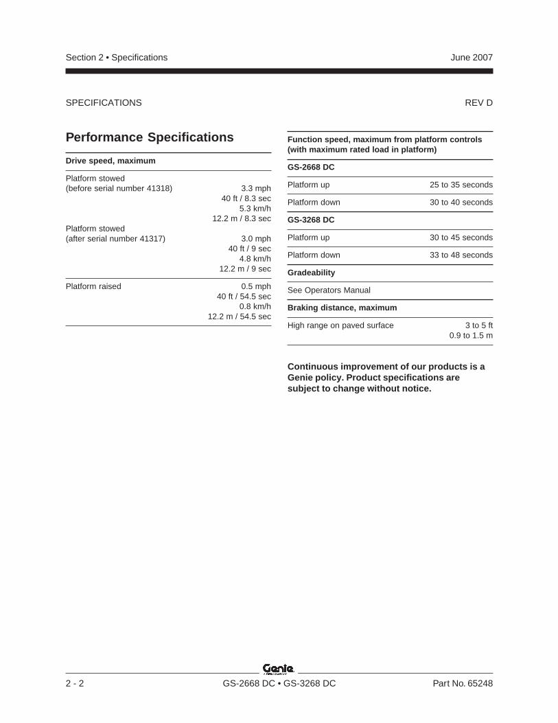
Performance Specifications
Drive speed, maximum
Platform stowed(before serial number 41318) 3.3 mph
40 ft / 8.3 sec5.3 km/h
12.2 m / 8.3 secPlatform stowed(after serial number 41317) 3.0 mph
40 ft / 9 sec4.8 km/h
12.2 m / 9 sec
Platform raised 0.5 mph40 ft / 54.5 sec
0.8 km/h12.2 m / 54.5 sec
Function speed, maximum from platform controls(with maximum rated load in platform)
GS-2668 DC
Platform up 25 to 35 seconds
Platform down 30 to 40 seconds
GS-3268 DC
Platform up 30 to 45 seconds
Platform down 33 to 48 seconds
Gradeability
See Operators Manual
Braking distance, maximum
High range on paved surface 3 to 5 ft0.9 to 1.5 m
Continuous improvement of our products is aGenie policy. Product specifications aresubject to change without notice.
REV D
Section 2 • SpecificationsJune 2007
Part No. 65248 GS-2668 DC • GS-3268 DC 2 - 3
SPECIFICATIONS
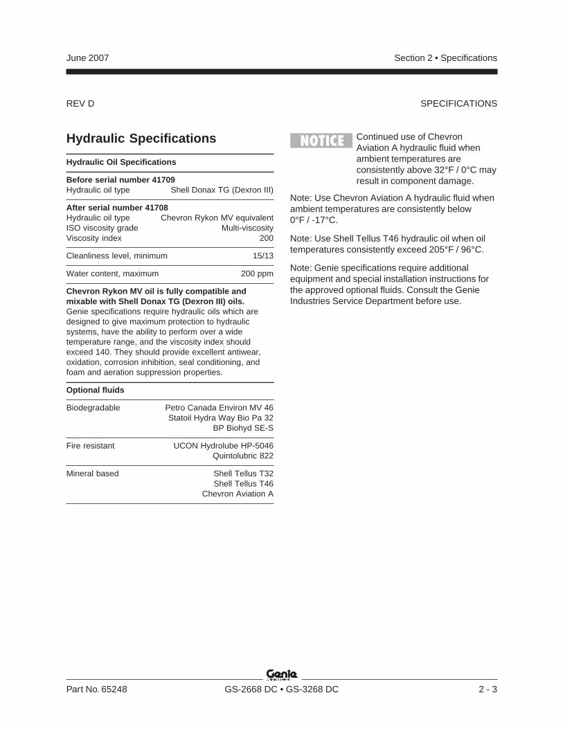
Hydraulic Specifications
Hydraulic Oil Specifications
Before serial number 41709Hydraulic oil type Shell Donax TG (Dexron III)
After serial number 41708Hydraulic oil type Chevron Rykon MV equivalentISO viscosity grade Multi-viscosityViscosity index 200
Cleanliness level, minimum 15/13
Water content, maximum 200 ppm
Chevron Rykon MV oil is fully compatible andmixable with Shell Donax TG (Dexron III) oils.Genie specifications require hydraulic oils which aredesigned to give maximum protection to hydraulicsystems, have the ability to perform over a widetemperature range, and the viscosity index shouldexceed 140. They should provide excellent antiwear,oxidation, corrosion inhibition, seal conditioning, andfoam and aeration suppression properties.
Optional fluids
Biodegradable Petro Canada Environ MV 46Statoil Hydra Way Bio Pa 32
BP Biohyd SE-S
Fire resistant UCON Hydrolube HP-5046Quintolubric 822
Mineral based Shell Tellus T32Shell Tellus T46
Chevron Aviation A
Continued use of ChevronAviation A hydraulic fluid whenambient temperatures areconsistently above 32°F / 0°C mayresult in component damage.
Note: Use Chevron Aviation A hydraulic fluid whenambient temperatures are consistently below0°F / -17°C.
Note: Use Shell Tellus T46 hydraulic oil when oiltemperatures consistently exceed 205°F / 96°C.
Note: Genie specifications require additionalequipment and special installation instructions forthe approved optional fluids. Consult the GenieIndustries Service Department before use.
REV D
Section 2 • Specifications June 2007
2 - 4 GS-2668 DC • GS-3268 DC Part No. 65248
SPECIFICATIONS
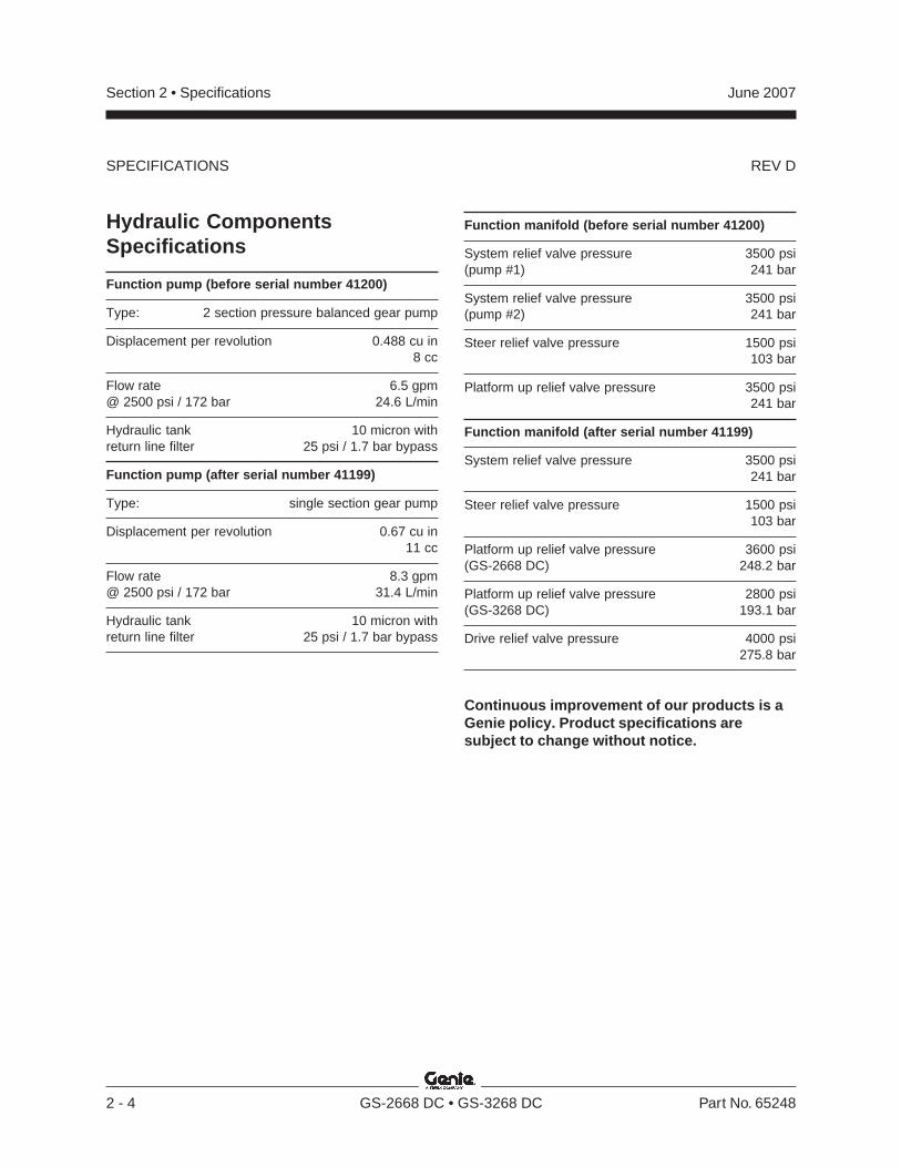
Hydraulic ComponentsSpecifications
Function pump (before serial number 41200)
Type: 2 section pressure balanced gear pump
Displacement per revolution 0.488 cu in8 cc
Flow rate 6.5 gpm@ 2500 psi / 172 bar 24.6 L/min
Hydraulic tank 10 micron withreturn line filter 25 psi / 1.7 bar bypass
Function pump (after serial number 41199)
Type: single section gear pump
Displacement per revolution 0.67 cu in11 cc
Flow rate 8.3 gpm@ 2500 psi / 172 bar 31.4 L/min
Hydraulic tank 10 micron withreturn line filter 25 psi / 1.7 bar bypass
Function manifold (before serial number 41200)
System relief valve pressure 3500 psi(pump #1) 241 bar
System relief valve pressure 3500 psi(pump #2) 241 bar
Steer relief valve pressure 1500 psi103 bar
Platform up relief valve pressure 3500 psi241 bar
Function manifold (after serial number 41199)
System relief valve pressure 3500 psi241 bar
Steer relief valve pressure 1500 psi103 bar
Platform up relief valve pressure 3600 psi(GS-2668 DC) 248.2 bar
Platform up relief valve pressure 2800 psi(GS-3268 DC) 193.1 bar
Drive relief valve pressure 4000 psi275.8 bar
Continuous improvement of our products is aGenie policy. Product specifications aresubject to change without notice.
REV D
Section 2 • SpecificationsJune 2007
Part No. 65248 GS-2668 DC • GS-3268 DC 2 - 5
SPECIFICATIONS
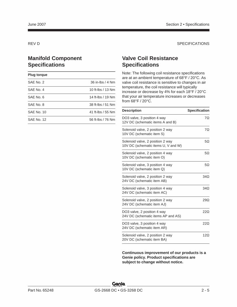
Manifold ComponentSpecifications
Plug torque
SAE No. 2 36 in-lbs / 4 Nm
SAE No. 4 10 ft-lbs / 13 Nm
SAE No. 6 14 ft-lbs / 19 Nm
SAE No. 8 38 ft-lbs / 51 Nm
SAE No. 10 41 ft-lbs / 55 Nm
SAE No. 12 56 ft-lbs / 76 Nm
Valve Coil ResistanceSpecificationsNote: The following coil resistance specificationsare at an ambient temperature of 68°F / 20°C. Asvalve coil resistance is sensitive to changes in airtemperature, the coil resistance will typicallyincrease or decrease by 4% for each 18°F / 20°Cthat your air temperature increases or decreasesfrom 68°F / 20°C.
Description Specification
DO3 valve, 3 position 4 way 7Ω12V DC (schematic items A and B)
Solenoid valve, 2 position 2 way 7Ω10V DC (schematic item S)
Solenoid valve, 2 position 2 way 5Ω10V DC (schematic items U, V and W)
Solenoid valve, 2 position 4 way 5Ω10V DC (schematic item O)
Solenoid valve, 3 position 4 way 5Ω10V DC (schematic item Q)
Solenoid valve, 2 position 2 way 34Ω24V DC (schematic item AB)
Solenoid valve, 3 position 4 way 34Ω24V DC (schematic item AC)
Solenoid valve, 2 position 2 way 29Ω24V DC (schematic item AJ)
DO3 valve, 2 position 4 way 22Ω24V DC (schematic items AP and AS)
DO3 valve, 3 position 4 way 22Ω24V DC (schematic item AR)
Solenoid valve, 2 position 2 way 12Ω20V DC (schematic item BA)
Continuous improvement of our products is aGenie policy. Product specifications aresubject to change without notice.
REV D
Section 2 • Specifications June 2007
2 - 6 GS-2668 DC • GS-3268 DC Part No. 65248
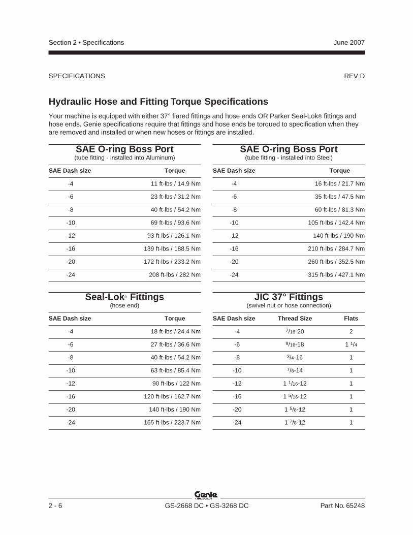
Hydraulic Hose and Fitting Torque SpecificationsYour machine is equipped with either 37° flared fittings and hose ends OR Parker Seal-Lok® fittings andhose ends. Genie specifications require that fittings and hose ends be torqued to specification when theyare removed and installed or when new hoses or fittings are installed.
SAE O-ring Boss Port(tube fitting - installed into Aluminum)
SAE Dash size Torque
-4 11 ft-lbs / 14.9 Nm
-6 23 ft-lbs / 31.2 Nm
-8 40 ft-lbs / 54.2 Nm
-10 69 ft-lbs / 93.6 Nm
-12 93 ft-lbs / 126.1 Nm
-16 139 ft-lbs / 188.5 Nm
-20 172 ft-lbs / 233.2 Nm
-24 208 ft-lbs / 282 Nm
SAE O-ring Boss Port(tube fitting - installed into Steel)
SAE Dash size Torque
-4 16 ft-lbs / 21.7 Nm
-6 35 ft-lbs / 47.5 Nm
-8 60 ft-lbs / 81.3 Nm
-10 105 ft-lbs / 142.4 Nm
-12 140 ft-lbs / 190 Nm
-16 210 ft-lbs / 284.7 Nm
-20 260 ft-lbs / 352.5 Nm
-24 315 ft-lbs / 427.1 Nm
Seal-Lok® Fittings(hose end)
SAE Dash size Torque
-4 18 ft-lbs / 24.4 Nm
-6 27 ft-lbs / 36.6 Nm
-8 40 ft-lbs / 54.2 Nm
-10 63 ft-lbs / 85.4 Nm
-12 90 ft-lbs / 122 Nm
-16 120 ft-lbs / 162.7 Nm
-20 140 ft-lbs / 190 Nm
-24 165 ft-lbs / 223.7 Nm
JIC 37° Fittings(swivel nut or hose connection)
SAE Dash size Thread Size Flats
-4 7/16-20 2
-6 9/16-18 1 1/4
-8 3/4-16 1
-10 7/8-14 1
-12 1 1/16-12 1
-16 1 5/16-12 1
-20 1 5/8-12 1
-24 1 7/8-12 1
SPECIFICATIONS
REV D
Section 2 • SpecificationsJune 2007
Part No. 65248 GS-2668 DC • GS-3268 DC 2 - 7
SPECIFICATIONS
b
c
a
da
b
c
b
Seal-Lok® fittings
1 Replace the O-ring. The O-ring must bereplaced anytime the seal has been broken.The O-ring cannot be re-used if the fitting orhose end has been tightened beyond fingertight.
Note: The O-rings used in the Parker Seal Lok®fittings and hose ends are custom-size O-rings.They are not standard SAE size O-rings. They areavailable in the O-ring field service kit.
2 Lubricate the O-ring before installation.
3 Be sure that the face seal O-ring is seated andretained properly.
4 Position the tube and nut squarely on the faceseal end of the fitting and tighten the nut fingertight.
5 Tighten the nut or fitting to the appropriatetorque per given size as shown in the table.
6 Operate all machine functions and inspect thehoses and fittings and related components toconfirm that there are no leaks.
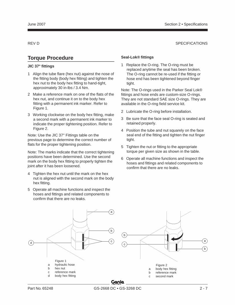
Figure 1a hydraulic hoseb hex nutc reference markd body hex fitting
Torque ProcedureJIC 37° fittings
1 Align the tube flare (hex nut) against the nose ofthe fitting body (body hex fitting) and tighten thehex nut to the body hex fitting to hand-tight,approximately 30 in-lbs / 3.4 Nm.
2 Make a reference mark on one of the flats of thehex nut, and continue it on to the body hexfitting with a permanent ink marker. Refer toFigure 1.
3 Working clockwise on the body hex fitting, makea second mark with a permanent ink marker toindicate the proper tightening position. Refer toFigure 2.
Note: Use the JIC 37° Fittings table on theprevious page to determine the correct number offlats for the proper tightening position.
Note: The marks indicate that the correct tighteningpositions have been determined. Use the secondmark on the body hex fitting to properly tighten thejoint after it has been loosened.
4 Tighten the hex nut until the mark on the hexnut is aligned with the second mark on the bodyhex fitting.
5 Operate all machine functions and inspect thehoses and fittings and related components toconfirm that there are no leaks.
Figure 2a body hex fittingb reference markc second mark
REV D
Section 2 • Specifications June 2007
2 - 8 GS-2668 DC • GS-3268 DC Part No. 65248
SPECIFICATIONS
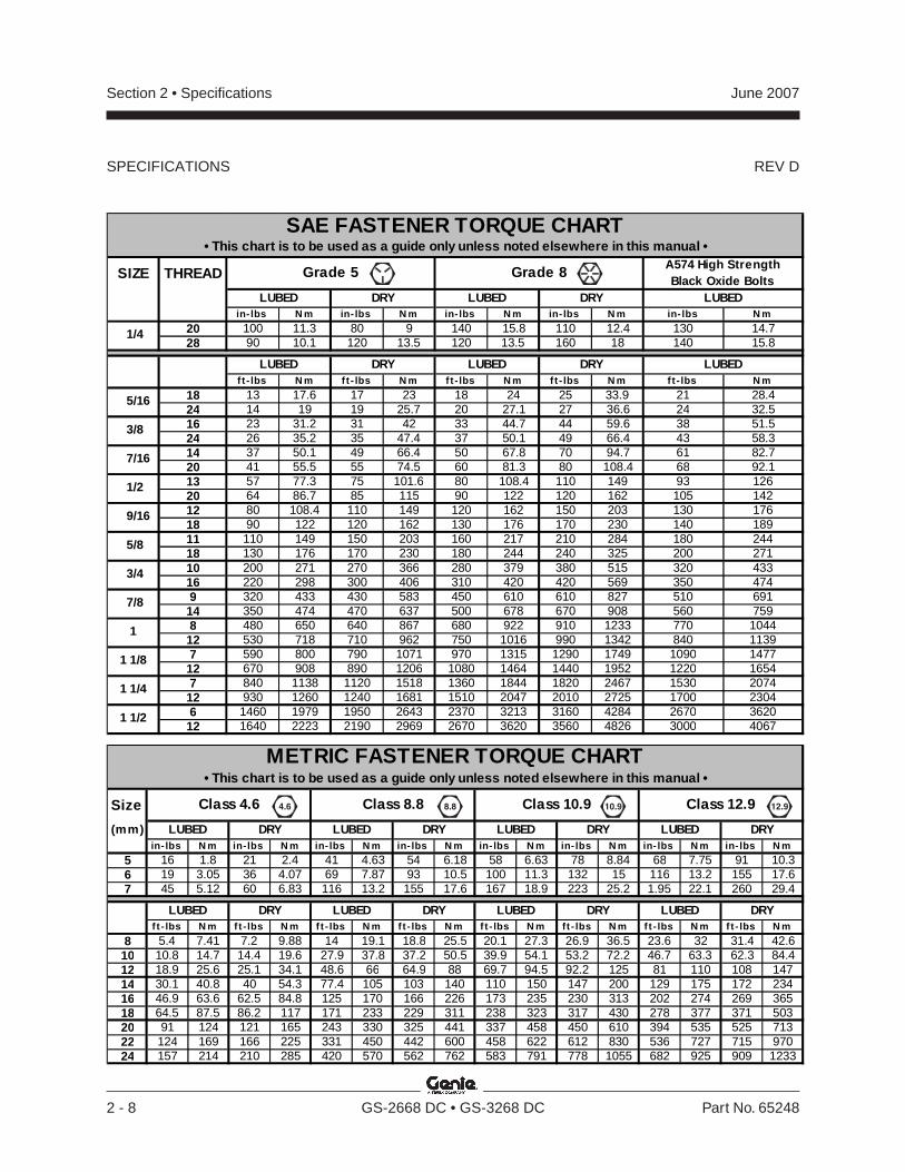
SIZE THREAD
in-lbs N m in- lbs N m in- lbs N m in- lbs N m in- lbs N m
20 100 11.3 80 9 140 15.8 110 12.4 130 14.728 90 10.1 120 13.5 120 13.5 160 18 140 15.8
f t - lbs N m ft- lbs N m ft- lbs N m ft- lbs N m ft- lbs N m
18 13 17.6 17 23 18 24 25 33.9 21 28.424 14 19 19 25.7 20 27.1 27 36.6 24 32.516 23 31.2 31 42 33 44.7 44 59.6 38 51.524 26 35.2 35 47.4 37 50.1 49 66.4 43 58.314 37 50.1 49 66.4 50 67.8 70 94.7 61 82.720 41 55.5 55 74.5 60 81.3 80 108.4 68 92.113 57 77.3 75 101.6 80 108.4 110 149 93 12620 64 86.7 85 115 90 122 120 162 105 14212 80 108.4 110 149 120 162 150 203 130 17618 90 122 120 162 130 176 170 230 140 18911 110 149 150 203 160 217 210 284 180 24418 130 176 170 230 180 244 240 325 200 27110 200 271 270 366 280 379 380 515 320 43316 220 298 300 406 310 420 420 569 350 4749 320 433 430 583 450 610 610 827 510 69114 350 474 470 637 500 678 670 908 560 7598 480 650 640 867 680 922 910 1233 770 104412 530 718 710 962 750 1016 990 1342 840 11397 590 800 790 1071 970 1315 1290 1749 1090 147712 670 908 890 1206 1080 1464 1440 1952 1220 16547 840 1138 1120 1518 1360 1844 1820 2467 1530 207412 930 1260 1240 1681 1510 2047 2010 2725 1700 23046 1460 1979 1950 2643 2370 3213 3160 4284 2670 362012 1640 2223 2190 2969 2670 3620 3560 4826 3000 4067
LUBEDDRYLUBED
SAE FASTENER TORQUE CHART
Grade 5
DRYLUBED
• This chart is to be used as a guide only unless noted elsewhere in this manual •A574 High Strength Black Oxide Bolts
Grade 8
LUBED
1/4
LUBED DRY LUBED DRY
1 1/2
9/16
5/8
3/4
7/8
1
1 1/8
1 1/4
5/16
3/8
7/16
1/2
Size
(mm)in- lbs N m in-lbs N m in- lbs N m in- lbs N m in- lbs N m in- lbs N m in- lbs N m in- lbs N m
5 16 1.8 21 2.4 41 4.63 54 6.18 58 6.63 78 8.84 68 7.75 91 10.36 19 3.05 36 4.07 69 7.87 93 10.5 100 11.3 132 15 116 13.2 155 17.67 45 5.12 60 6.83 116 13.2 155 17.6 167 18.9 223 25.2 1.95 22.1 260 29.4
f t - lbs N m ft-lbs N m ft- lbs N m ft- lbs N m ft- lbs N m ft- lbs N m ft- lbs N m ft- lbs N m
8 5.4 7.41 7.2 9.88 14 19.1 18.8 25.5 20.1 27.3 26.9 36.5 23.6 32 31.4 42.610 10.8 14.7 14.4 19.6 27.9 37.8 37.2 50.5 39.9 54.1 53.2 72.2 46.7 63.3 62.3 84.412 18.9 25.6 25.1 34.1 48.6 66 64.9 88 69.7 94.5 92.2 125 81 110 108 14714 30.1 40.8 40 54.3 77.4 105 103 140 110 150 147 200 129 175 172 23416 46.9 63.6 62.5 84.8 125 170 166 226 173 235 230 313 202 274 269 36518 64.5 87.5 86.2 117 171 233 229 311 238 323 317 430 278 377 371 50320 91 124 121 165 243 330 325 441 337 458 450 610 394 535 525 71322 124 169 166 225 331 450 442 600 458 622 612 830 536 727 715 97024 157 214 210 285 420 570 562 762 583 791 778 1055 682 925 909 1233
LUBED DRY LUBED DRYLUBED DRY LUBED DRY
LUBEDDRYLUBED
Class 12.9Class 4.6
DRYLUBED
METRIC FASTENER TORQUE CHART• This chart is to be used as a guide only unless noted elsewhere in this manual •
LUBED DRY
Class 10.9Class 8.8
DRY
10.9 12.98.84.6
Section 3 • Scheduled Maintenance ProceduresJune 2007
Part No. 65248 GS-2668 DC • GS-3268 DC 3 - 1
Scheduled Maintenance Procedures
Observe and Obey:
Maintenance inspections shall be completed bya person trained and qualified on themaintenance of this machine.
Scheduled maintenance inspections shall becompleted daily, quarterly, semi-annually,annually and every 2 years as specified on theMaintenance Inspection Report.
Failure to perform each procedureas presented and scheduled couldresult in death, serious injury orsubstantial damage.
Immediately tag and remove from service adamaged or malfunctioning machine.
Repair any machine damage or malfunctionbefore operating the machine.
Use only Genie approved replacement parts.
Machines that have been out of service for aperiod longer than 3 months must complete thequarterly inspection.
Unless otherwise specified, perform eachmaintenance procedure with the machine in thefollowing configuration:
· Machine parked on a firm, level surface
· Platform in the stowed position
· Key switch in the off position with the keyremoved
· The red Emergency Stop button in the offposition at both ground and platform controls
· Wheels chocked
· All external AC power supply disconnectedfrom the machine
About This Section
This section contains detailed procedures for eachscheduled maintenance inspection.
Each procedure includes a description, safetywarnings and step-by-step instructions.
Symbols Legend
Safety alert symbol—used to alertpersonnel to potential personalinjury hazards. Obey all safetymessages that follow this symbolto avoid possible injury or death.
Indicates an imminently hazardoussituation which, if not avoided, willresult in death or serious injury.
Indicates a potentially hazardoussituation which, if not avoided,could result in death or seriousinjury.
Indicates a potentially hazardoussituation which, if not avoided,may cause minor or moderateinjury.
Indicates a potentially hazardoussituation which, if not avoided,may result in property damage.
Indicates that a specific result is expected afterperforming a series of steps.
Indicates that an incorrect result has occurredafter performing a series of steps.
Section 3 • Scheduled Maintenance Procedures June 2007
3 - 2 GS-2668 DC • GS-3268 DC Part No. 65248
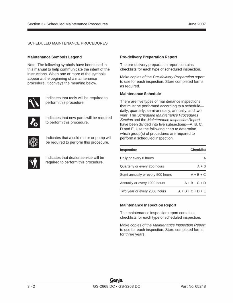
Maintenance Symbols Legend
Note: The following symbols have been used inthis manual to help communicate the intent of theinstructions. When one or more of the symbolsappear at the beginning of a maintenanceprocedure, it conveys the meaning below.
Indicates that tools will be required toperform this procedure.
Indicates that new parts will be requiredto perform this procedure.
Indicates that a cold motor or pump willbe required to perform this procedure.
Indicates that dealer service will berequired to perform this procedure.
Pre-delivery Preparation Report
The pre-delivery preparation report containschecklists for each type of scheduled inspection.
Make copies of the Pre-delivery Preparation reportto use for each inspection. Store completed formsas required.
Maintenance Schedule
There are five types of maintenance inspectionsthat must be performed according to a schedule—daily, quarterly, semi-annually, annually, and twoyear. The Scheduled Maintenance ProceduresSection and the Maintenance Inspection Reporthave been divided into five subsections—A, B, C,D and E. Use the following chart to determinewhich group(s) of procedures are required toperform a scheduled inspection.
Inspection Checklist
Daily or every 8 hours A
Quarterly or every 250 hours A + B
Semi-annually or every 500 hours A + B + C
Annually or every 1000 hours A + B + C + D
Two year or every 2000 hours A + B + C + D + E
Maintenance Inspection Report
The maintenance inspection report containschecklists for each type of scheduled inspection.
Make copies of the Maintenance Inspection Reportto use for each inspection. Store completed formsfor three years.
SCHEDULED MAINTENANCE PROCEDURES
Genie Industries USA18340 NE 76th StreetPO Box 97030Redmond, WA 98073-9730(425) 881-1800
Copyright © 2002 by Genie Industries. Genie® is a registered trademark of GenieIndustries. Rev B
Genie UKThe Maltings, Wharf Road
Grantham, LincolnshireNG31- 6BH England
(44) 1476-584333
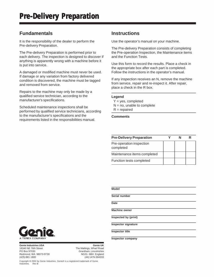
Pre-DeliverPre-DeliverPre-DeliverPre-DeliverPre-Delivery Preparationy Preparationy Preparationy Preparationy Preparation
Pre-Delivery Preparation Y N R
Pre-operation inspectioncompleted
Maintenance items completed
Function tests completed
Model
Serial number
Date
Machine owner
Inspected by (print)
Inspector signature
Inspector title
Inspector company
Instructions
Use the operator’s manual on your machine.
The Pre-delivery Preparation consists of completingthe Pre-operation Inspection, the Maintenance itemsand the Function Tests.
Use this form to record the results. Place a check inthe appropriate box after each part is completed.Follow the instructions in the operator’s manual.
If any inspection receives an N, remove the machinefrom service, repair and re-inspect it. After repair,place a check in the R box.
LegendY = yes, completedN = no, unable to completeR = repaired
Comments
Fundamentals
It is the responsibility of the dealer to perform thePre-delivery Preparation.
The Pre-delivery Preparation is performed prior toeach delivery. The inspection is designed to discover ifanything is apparently wrong with a machine before itis put into service.
A damaged or modified machine must never be used.If damage or any variation from factory deliveredcondition is discovered, the machine must be taggedand removed from service.
Repairs to the machine may only be made by aqualified service technician, according to themanufacturer's specifications.
Scheduled maintenance inspections shall beperformed by qualified service technicians, accordingto the manufacturer's specifications and therequirements listed in the responsibilities manual.
Section 3 • Scheduled Maintenance Procedures June 2007
3 - 4 GS-2668 DC • GS-3268 DC Part No. 65248
This page intentionally left blank.
Section 3 • Scheduled Maintenance ProceduresJune 2007
Part No. 65248 GS-2668 DC • GS-3268 DC 3 - 5
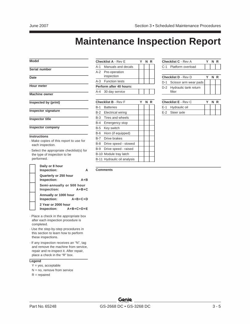
Checklist A - Rev E Y N R
A-1 Manuals and decals
A-2 Pre-operationinspection
A-3 Function tests
Perform after 40 hours:
A-4 30 day service
Checklist B - Rev F Y N R
B-1 Batteries
B-2 Electrical wiring
B-3 Tires and wheels
B-4 Emergency stop
B-5 Key switch
B-6 Horn (if equipped)
B-7 Drive brakes
B-8 Drive speed - stowed
B-9 Drive speed - raised
B-10 Module tray latch
B-11 Hydraulic oil analysis
Checklist C - Rev A Y N R
C-1 Platform overload
Checklist D - Rev D Y N R
D-1 Scissor arm wear pads
D-2 Hydraulic tank returnfilter
Checklist E - Rev C Y N R
E-1 Hydraulic oil
E-2 Steer axle
Instructions· Make copies of this report to use for
each inspection.
· Select the appropriate checklist(s) forthe type of inspection to beperformed.
Daily or 8 hourInspection: A
Quarterly or 250 hourInspection: A+B
Semi-annually or 500 hourInspection: A+B+C
Annually or 1000 hourInspection: A+B+C+D
2 Year or 2000 hourInspection: A+B+C+D+E
· Place a check in the appropriate boxafter each inspection procedure iscompleted.
· Use the step-by-step procedures inthis section to learn how to performthese inspections.
· If any inspection receives an “N”, tagand remove the machine from service,repair and re-inspect it. After repair,place a check in the “R” box.
LegendY = yes, acceptableN = no, remove from serviceR = repaired
Maintenance Inspection Report
Model
Serial number
Date
Hour meter
Machine owner
Inspected by (print)
Inspector signature
Inspector title
Inspector company
Comments
REV E
Section 3 • Scheduled Maintenance Procedures June 2007
3 - 6 GS-2668 DC • GS-3268 DC Part No. 65248
Checklist A Procedures
A-1Inspect the Manuals and DecalsGenie specifications require that this procedure beperformed every 8 hours or daily, whichevercomes first.
Maintaining the operator’s and safety manuals ingood condition is essential to safe machineoperation. Manuals are included with eachmachine and should be stored in the containerprovided in the platform. An illegible or missingmanual will not provide safety and operationalinformation necessary for a safe operatingcondition.
In addition, maintaining all of the safety andinstructional decals in good condition is mandatoryfor safe machine operation. Decals alert operatorsand personnel to the many possible hazardsassociated with using this machine. They alsoprovide users with operation and maintenanceinformation. An illegible decal will fail to alertpersonnel of a procedure or hazard and couldresult in unsafe operating conditions.
1 Check to make sure that the operator's andsafety manuals are present and complete in thestorage container on the platform.
2 Examine the pages of each manual to be surethat they are legible and in good condition.
Result: The operator's manual is appropriate forthe machine and all manuals are legible and ingood condition.
Result: The operator's manual is notappropriate for the machine or all manuals arenot in good condition or is illegible. Remove themachine from service until the manual isreplaced.
3 Open the operator's manual to the decalsinspection section. Carefully and thoroughlyinspect all decals on the machine for legibilityand damage.
Result: The machine is equipped with allrequired decals, and all decals are legible andin good condition.
Result: The machine is not equipped with allrequired decals, or one or more decals areillegible or in poor condition. Remove themachine from service until the decals arereplaced.
4 Always return the manuals to the storagecontainer after use.
Note: Contact your authorized Genie distributor orGenie Industries if replacement manuals or decalsare needed.
REV E
Section 3 • Scheduled Maintenance ProceduresJune 2007
Part No. 65248 GS-2668 DC • GS-3268 DC 3 - 7
CHECKLIST A PROCEDURES
A-2Perform Pre-operation InspectionGenie specifications require that this procedure beperformed every 8 hours or daily, whichevercomes first.
Completing a Pre-operation Inspection is essentialto safe machine operation. The Pre-operationInspection is a visual inspection performed by theoperator prior to each work shift. The inspection isdesigned to discover if anything is apparentlywrong with a machine before the operator performsthe function tests. The Pre-operation Inspectionalso serves to determine if routine maintenanceprocedures are required.
Complete information to perform this procedure isavailable in the appropriate Operator's Manual.Refer to the Operator's Manual on your machine.
A-3Perform Function TestsGenie specifications require that this procedure beperformed every 8 hours or daily, whichevercomes first.
Completing the function tests is essential to safemachine operation. Function tests are designed todiscover any malfunctions before the machine isput into service. A malfunctioning machine mustnever be used. If malfunctions are discovered, themachine must be tagged and removed fromservice.
Complete information to perform this procedure isavailable in the appropriate Operator's Manual.Refer to the Operator's Manual on your machine.
A-4Perform 30 Day Service
The 30 day maintenance procedure is a one-timesequence of procedures to be performed after thefirst 30 days or 40 hours of use. After this interval,refer to the maintenance checklists for continuedscheduled maintenance.
1 Perform the following maintenance procedures:· B-3 Inspect the Tires, Wheels and
Castle Nut Torque· D-2 Replace the Hydraulic Tank Return
Filter
REV F
Section 3 • Scheduled Maintenance Procedures June 2007
3 - 8 GS-2668 DC • GS-3268 DC Part No. 65248
Checklist B Procedures
B-1Inspect the Batteries
Genie specifications require that this procedure beperformed every 250 hours or quarterly, whichevercomes first.
Proper battery condition is essential to goodmachine performance and operational safety.Improper fluid levels or damaged cables andconnections can result in component damage andhazardous conditions.
Electrocution hazard. Contact withelectrically charged circuits couldresult in death or serious injury.Remove all rings, watches andother jewelry.
Bodily injury hazard. Batteriescontain acid. Avoid spilling orcontacting battery acid. Neutralizebattery acid spills with baking sodaand water.
1 Put on protective clothing and eye wear.
2 Be sure that the battery cable connections arefree of corrosion.
Note: Adding terminal protectors and a corrosionpreventative sealant will help eliminate corrosionon the battery terminals and cables.
3 Models without maintenance-free or sealedbatteries: Be sure that the battery hold downsand cable connections are tight. Proceed tostep 4.Models with maintenance-free or sealedbatteries: Be sure that the battery hold downsand cable connections are tight. Proceed tostep 12.
4 Fully charge the batteries and allow thebatteries to rest at least 6 hours.
5 Remove the battery vent caps and check thespecific gravity of each battery cell with ahydrometer. Note the results.
6 Check the ambient air temperature and adjustthe specific gravity reading for each cell asfollows:
• Add 0.004 to the reading of each cell forevery 10° / 5.5° C above 80° F / 26.7° C.
• Subtract 0.004 from the reading of each cell forevery 10° / 5.5° C below 80° F / 26.7° C.
Result: All battery cells display an adjustedspecific gravity of 1.277 or higher. The batteryis fully charged. Proceed to step 11.
Result: One or more battery cells display aspecific gravity of 1.217 or below. Proceed tostep 8.
7 Perform an equalizing charge OR fully chargethe batteries and allow the batteries to rest atleast 6 hours.
REV F
Section 3 • Scheduled Maintenance ProceduresJune 2007
Part No. 65248 GS-2668 DC • GS-3268 DC 3 - 9
8 Remove the battery vent caps and check thespecific gravity of each battery cell with ahydrometer. Note the results.
9 Check the ambient air temperature and adjustthe specific gravity reading for each cell asfollows:
• Add 0.004 to the reading of each cell forevery 10° / 5.5° C above 80° F / 26.7° C.
• Subtract 0.004 from the reading of each cell forevery 10° / 5.5° C below 80° F / 26.7° C.
Result: All battery cells display a specific gravityof 1.277 or greater. The battery is fully charged.Proceed to step 13.
Result: The difference in specific gravityreadings between cells is greater than 0.1 ORthe specific gravity of one or more cells is lessthan 1.177. Replace the battery.
10 Check the battery acid level. If needed,replenish with distilled water to 1/8 inch / 3 mmbelow the bottom of the battery fill tube. Do notoverfill.
11 Install the vent caps and neutralize anyelectrolyte that may have spilled.
All models:
12 Check each battery pack and confirm that thebatteries are wired correctly. Refer to theBattery Connection Diagram decal on themachine.
13 Inspect the battery charger plug and pigtail fordamage or excessive insulation wear. Replaceas required.
14 Thoroughly clean the exterior of the batterycharger. Inspect and tighten, if necessary, allwire connections at the charger.
15 Connect the battery charger to a properlygrounded 115V or 230V single phase AC powersupply.
Result: The charger, after a short delay, shouldstart as indicated by the transformer hum, andbegin charging the batteries.
Note: For best results, always use a three-conductor, number 14 AWG / 1.5 mm heavy dutywith ground extension cord, in as short a length aspossible. Refer to the operating instructions for thebattery charger.
Note: If you have any further questions regardingthe battery charger operation, please contact theGenie Industries Scissor Service Department.
CHECKLIST B PROCEDURES
REV F
Section 3 • Scheduled Maintenance Procedures June 2007
3 - 10 GS-2668 DC • GS-3268 DC Part No. 65248
CHECKLIST B PROCEDURES
B-2Inspect the Electrical Wiring
Genie specifications require that this procedure beperformed every 250 hours or quarterly, whichevercomes first.
Maintaining electrical wiring in good condition isessential to safe operation and good machineperformance. Failure to find and replace burnt,chafed, corroded or pinched wires could result inunsafe operating conditions and may causecomponent damage.
Electrocution hazard. Contact withelectrically charged circuits couldresult in death or serious injury.Remove all rings, watches andother jewelry.
1 Inspect the underside of the chassis fordamaged or missing ground strap(s).
2 Inspect the following areas for burnt, chafed,corroded and loose wires:
· Ground control panel
· Hydraulic power unit module tray
· Battery pack module tray
· Scissor arms
· Platform controls
3 Inspect for a liberal coating of dielectric greasein the following locations:
· Between the ECM and platform controls
· All wire harness connectors
· Level sensor
4 Turn the key switch to ground control and pullout the red Emergency Stop button to the onposition at both the ground and platformcontrols.
5 Raise the platform approximately 10 feet / 3 mfrom the ground.
6 Rotate the safety arm away from the machineand let it hang down.
7 Lower the platform onto the safety arm.
Crushing hazard. Keep handsclear of the safety arm whenlowering the platform.
8 Inspect the center chassis area and scissorarms for burnt, chafed and pinched cables.
9 Inspect the following areas for burnt, chafed,corroded, pinched and loose wires:
· ECM to platform controls
· Power to platform wiring
10 Inspect for a liberal coating of dielectric greasein all connections between the ECM and theplatform controls.
11 Raise the platform and return the safety arm tothe stowed position.
12 Lower the platform to the stowed position andturn the machine off.
REV F
Section 3 • Scheduled Maintenance ProceduresJune 2007
Part No. 65248 GS-2668 DC • GS-3268 DC 3 - 11
CHECKLIST B PROCEDURES
B-3Inspect the Tires, Wheels andCastle Nut Torque
Genie specifications require that this procedure beperformed every 250 hours or quarterly, whichevercomes first.
Maintaining the tires and wheels in goodcondition, including proper wheel fastenertorque, is essential to safe operation and goodperformance. Tire and/or wheel failure could resultin a machine tip-over. Component damage mayalso result if problems are not discovered andrepaired in a timely fashion.
1 Check the tire surface and sidewalls for cuts,cracks, punctures and unusual wear.
2 Check each wheel for damage, bends andcracks.
3 Remove the castle nut lock plate or cotter pinand check each castle nut for proper torque.Refer to Maintenance Procedure E-2,Grease the Steer Axle and Wheel Bearings.
Note: Always replace the cotter pin with a new onewhen removing the castle nut or when checkingthe torque of the castle nut.
4 Check each lug bolt for proper torque. Refer toSection 2, Specifications.
5 Install the castle nut lock plate using a new lockwasher OR install a new cotter pin and secure.
B-4Test the Emergency StopGenie specifications require that this procedure beperformed every 250 hours or quarterly, whichevercomes first.
A properly functioning Emergency Stop is essentialfor safe machine operation. An improperlyoperating red Emergency Stop buttonwill fail to shut off power and stop all machinefunctions, resulting in a hazardous situation.
Note: As a safety feature, selecting and operatingthe ground controls will override the platformcontrols, except the platform red Emergency Stopbutton.
1 Turn the key switch to ground control and pullout the red Emergency Stop button to the onposition at both the ground and platformcontrols.
2 Push in the red Emergency Stop button at theground controls to the off position.
Result: No machine functions should operate.
3 Turn the key switch to platform control and pullout the red Emergency Stop button to the onposition at both the ground and platformcontrols.
4 Push down the red Emergency Stop button atthe platform controls to the off position.
Result: No machine functions should operate.
Note: The red Emergency Stop button at theground controls will stop all machine operation,even if the key switch is turned to platform control.
REV F
Section 3 • Scheduled Maintenance Procedures June 2007
3 - 12 GS-2668 DC • GS-3268 DC Part No. 65248
CHECKLIST B PROCEDURES
B-6Test the Automotive-style Horn(if equipped)Genie specifications require that this procedure beperformed every 250 hours or quarterly, whichevercomes first.
A functioning horn is essential to safe machineoperation. The horn is activated at the platformcontrols and sounds at the ground as a warning toground personnel. An improperly functioning hornwill prevent the operator from alerting groundpersonnel of hazards or unsafe conditions.
1 Turn the key switch to platform control andpull out the red Emergency Stop button to theon position at both the ground and platformcontrols.
2 Push down the horn button at the platformcontrols.
Result: The horn should sound.
B-5Test the Key SwitchGenie specifications require that this procedure beperformed every 250 hours or quarterly, whichevercomes first.
Proper key switch action and response is essentialto safe machine operation. The machine can beoperated from the ground or platform controls andthe activation of one or the other is accomplishedwith the key switch. Failure of the key switch toactivate the appropriate control panel could causea hazardous operating situation.
Note: Perform this procedure from the groundusing the platform controls. Do not stand in theplatform.
1 Pull out the red Emergency Stop button to theon position at both the ground and platformcontrols.
2 Turn the key switch to platform control.
3 Check the platform up/down function from theground controls.
Result: The machine functions should notoperate.
4 Turn the key switch to ground control.
5 Check the machine functions from the platformcontrols.
Result: The machine functions should notoperate.
6 Turn the key switch to the off position.
Result: No function should operate.
REV F
Section 3 • Scheduled Maintenance ProceduresJune 2007
Part No. 65248 GS-2668 DC • GS-3268 DC 3 - 13
CHECKLIST B PROCEDURES
B-7Test the Drive Brakes
Genie specifications require that this procedure beperformed every 250 hours or quarterly, whichevercomes first.
Proper brake action is essential to safe machineoperation. The drive brake function should operatesmoothly, free of hesitation and unusualnoise. Hydraulically-released individual wheelbrakes can appear to operate normally when notfully operational.
Note: Perform this procedure with the machine onincline button at the platform controls in the offposition (LED light should be off) and the platformextension deck fully retracted.
1 Mark a test line on the ground for reference.
2 Turn the key switch to platform control and pullout the red Emergency Stop button to the onposition at both the ground and platformcontrols.
3 After serial number 41199: Press the drivefunction select button.
4 Press and hold the function enable switch onthe joystick.
5 Choose a point on the machine; i.e., contactpatch of a tire, as a visual reference for usewhen crossing the test line.
6 Bring the machine to top drive speed beforereaching the test line. Release the functionenable switch or the joystick when yourreference point on the machine crosses the testline.
7 Measure the distance between the test line andyour machine reference point. Refer to Section2, Specifications.
Note: The brakes must be able to hold the machineon any slope it is able to climb.
B-8Test the Drive Speed -Stowed Position
Genie specifications require that this procedure beperformed every 250 hours or quarterly, whichevercomes first.
Proper drive functions are essential to safemachine operation. The drive function shouldrespond quickly and smoothly to operator control.Drive performance should also be free of hesitationand unusual noise over the entire proportionallycontrolled speed range.
1 Create start and finish lines by marking twolines on the ground 40 feet / 12.2 m apart.
2 Turn the key switch to platform control and pullout the red Emergency Stop button to the onposition at both the ground and platformcontrols.
3 After serial number 41199: Press the drivefunction select button.
4 Choose a point on the machine; i.e., contactpatch of a tire, as a visual reference for usewhen crossing the start and finish lines.
5 Bring the machine to top drive speed beforereaching the start line. Begin timing when yourreference point on the machine crosses thestart line.
6 Continue at full speed and note the time whenyour reference point on the machine passesover the finish line. Refer to Section 2,Specifications.
REV F
Section 3 • Scheduled Maintenance Procedures June 2007
3 - 14 GS-2668 DC • GS-3268 DC Part No. 65248
CHECKLIST B PROCEDURES
B-9Test the Drive Speed -Raised Position
Genie specifications require that this procedure beperformed every 250 hours or quarterly, whichevercomes first.
Proper drive functions are essential to safemachine operation. The drive function shouldrespond quickly and smoothly to operator control.Drive performance should also be free of hesitationand unusual noise over the entire proportionallycontrolled speed range.
1 Create start and finish lines by marking twolines on the ground 40 feet / 12.2 m apart.
2 Turn the key switch to platform control and pullout the red Emergency Stop button to the onposition at both the ground and platformcontrols.
3 After serial number 41199: Press the drivefunction select button.
4 Raise the platform approximately 6 ft / 2 m.
5 Choose a point on the machine; i.e., contactpatch of a tire, as a visual reference for usewhen crossing the start and finish lines.
6 Bring the machine to top drive speed beforereaching the start line. Begin timing when yourreference point on the machine crosses thestart line.
7 Continue at full speed and note the time whenyour reference point on the machine passesover the finish line. Refer to Section 2,Specifications.
B-10Check the Module Tray LatchComponents
Genie specifications require that this procedure beperformed every 250 hours or quarterly, whichevercomes first.
Maintaining the module tray latch components ingood condition is essential to good performanceand service life. Failure to detect worn out latchcomponents may result in module trays openingunexpectedly, creating an unsafe operatingcondition.
1 Open both module trays and lubricate eachmodule tray latch. Using light oil, apply a fewdrops to the side of the latch mechanism.
2 Inspect for and tighten any loose fasteners.
REV F
Section 3 • Scheduled Maintenance ProceduresJune 2007
Part No. 65248 GS-2668 DC • GS-3268 DC 3 - 15
CHECKLIST B PROCEDURES
B-11Perform Hydraulic Oil Analysis
Genie specifications require that this procedure beperformed every 250 hours or quarterly, whichevercomes first.
Replacement or testing of the hydraulic oil isessential for good machine performance andservice life. Dirty oil and a clogged suction strainermay cause the machine to perform poorly andcontinued use may cause component damage.Extremely dirty conditions may require oil changesto be performed more often.
Note: Before replacing the hydraulic oil, the oil maybe tested by an oil distributor for specific levels ofcontamination to verify that changing the oil isnecessary. If the hydraulic oil is not replaced atthe two year inspection, test the oil quarterly.Replace the oil when it fails the test. See E-1,Test or Replace the Hydraulic Oil.
REV A
Section 3 • Scheduled Maintenance Procedures June 2007
3 - 16 GS-2668 DC • GS-3268 DC Part No. 65248
Checklist C Procedure
C-1Test thePlatform Overload System(if equipped)
Note: Genie specifications require that thisprocedure be performed every 500 hours or sixmonths, whichever comes first OR when themachine fails to lift the maximum rated load.
Testing the platform overload system regularly isessential to safe machine operation. Continueduse of an improperly operating platform overloadsystem could result in the system not sensing anoverloaded platform condition. Machine stabilitycould be compromised resulting in the machinetipping over.
The platform overload system is designed toprevent machine operation in the event themachine is overloaded. Models equipped with theplatform overload option are provided with twoadditional machine control components: theoverload pressure switch and a maximum heightlimit switch.
The overload pressure switch, which is adjustableand located at the barrel-end of the lift cylinder, isused to determine when the hydraulic lift cylinderrequires too much pressure to support the loadinside the platform. When this occurs, the pressureswitch will send a signal to the ECM, which will notallow the machine to function until the extra weightis removed from the platform.
The maximum height limit switch, located in thecenter of the drive chassis under the scissor armsat the steer end of the machine, is used to disablethe lift valve coil when the platform is nearmaximum height. When activated, the limit switchkeeps the lift cylinder from going over lift reliefwhich would cause the pressure switch to falselyindicate an overload condition.
1 Disconnect the platform controls from themachine at the platform.
2 Open the hydraulic tray door and locate theplatform controls wire harness to ElectronicControl Module (ECM) wire harness quickdisconnect.
3 Tag and disconnect the platform controls wireharness from the ECM wire harness.
4 Securely connect the platform controls to theECM wire harness.
REV A
Section 3 • Scheduled Maintenance ProceduresJune 2007
Part No. 65248 GS-2668 DC • GS-3268 DC 3 - 17
CHECKLIST C PROCEDURE
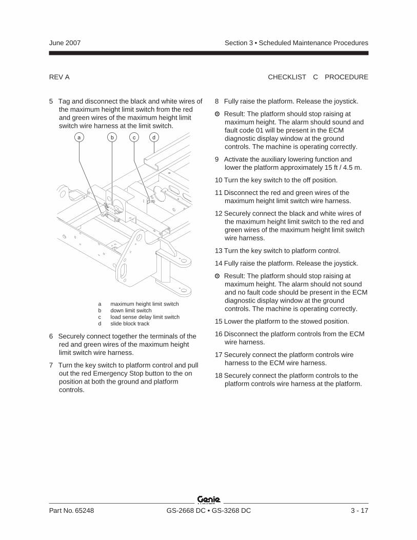
5 Tag and disconnect the black and white wires ofthe maximum height limit switch from the redand green wires of the maximum height limitswitch wire harness at the limit switch.
a maximum height limit switchb down limit switchc load sense delay limit switchd slide block track
6 Securely connect together the terminals of thered and green wires of the maximum heightlimit switch wire harness.
7 Turn the key switch to platform control and pullout the red Emergency Stop button to the onposition at both the ground and platformcontrols.
8 Fully raise the platform. Release the joystick.
Result: The platform should stop raising atmaximum height. The alarm should sound andfault code 01 will be present in the ECMdiagnostic display window at the groundcontrols. The machine is operating correctly.
9 Activate the auxiliary lowering function andlower the platform approximately 15 ft / 4.5 m.
10 Turn the key switch to the off position.
11 Disconnect the red and green wires of themaximum height limit switch wire harness.
12 Securely connect the black and white wires ofthe maximum height limit switch to the red andgreen wires of the maximum height limit switchwire harness.
13 Turn the key switch to platform control.
14 Fully raise the platform. Release the joystick.
Result: The platform should stop raising atmaximum height. The alarm should not soundand no fault code should be present in the ECMdiagnostic display window at the groundcontrols. The machine is operating correctly.
15 Lower the platform to the stowed position.
16 Disconnect the platform controls from the ECMwire harness.
17 Securely connect the platform controls wireharness to the ECM wire harness.
18 Securely connect the platform controls to theplatform controls wire harness at the platform.
REV D
Section 3 • Scheduled Maintenance Procedures June 2007
3 - 18 GS-2668 DC • GS-3268 DC Part No. 65248
Checklist D Procedures
D-1Check the Scissor Arm WearPads
Genie requires that this procedure be performedevery 1000 hours or annually, whichever comesfirst.
Maintaining the scissor arm wear pads in goodcondition is essential to safe machine operation.Continued use of worn out wear pads may result incomponent damage and unsafe operatingconditions.
1 Measure the thickness of each chassis wearpad at the steer end of the machine.
Result: The measurement is 5/16 inch / 8 mm ormore. Proceed to step 2.
Result: The measurement is less than5/16 inch / 8 mm. Replace both wear pads.
2 Measure the thickness of each chassis wearpad at the non-steer end of the machine.
Result: The measurement is 5/16 inch / 8 mm ormore. Proceed to step 3.
Result: The measurement is less than5/16 inch / 8 mm. Replace both wear pads.
3 Measure the thickness of each platform scissorarm wear pad at the steer end of the machine.
Result: The measurement is 5/16 inch / 8 mm ormore. Proceed to step 4.
Result: The measurement is less than5/16 inch / 8 mm. Replace both wear pads.
4 Measure the thickness of each platform scissorarm wear pad at the non-steer end of themachine.
Result: The measurement is 5/16 inch / 8 mm ormore.
Result: The measurement is less than5/16 inch / 8 mm. Replace both wear pads.
REV D
Section 3 • Scheduled Maintenance ProceduresJune 2007
Part No. 65248 GS-2668 DC • GS-3268 DC 3 - 19
D-2Replace the Hydraulic TankReturn Filter
Genie requires that this procedure be performedevery 1000 hours or annually, whichever comesfirst.
Replacement of the hydraulic tank return filter isessential for good machine performance andservice life. A dirty or clogged filter may cause themachine to perform poorly and continued use maycause component damage. Extremely dirtyconditions may require that the filter be replacedmore often.
Beware of hot oil. Contact withhot oil may cause severe burns.
Note: The hydraulic tank return filter is mounted onthe function manifold next to the hydraulic powerunit.
1 Clean the area around the oil filter. Remove thefilter with an oil filter wrench.
2 Apply a thin layer of fresh oil to the new oil filtergasket.
3 Install the new filter and tighten it securely byhand.
4 Use a permanent ink marker to write the dateand number of hours from the hour meter(if equipped) on the filter.
5 Turn the key switch to ground control and pullout the red Emergency Stop button to the onposition at both the ground and platformcontrols.
6 Raise the platform approximately 6 ft / 2 m.
7 Inspect the filter and related components tobe sure that there are no leaks.
8 Clean up any oil that may have spilled.
CHECKLIST D PROCEDURE
REV C
Section 3 • Scheduled Maintenance Procedures June 2007
3 - 20 GS-2668 DC • GS-3268 DC Part No. 65248
Checklist E Procedures
Open Closed
E-1Test or Replace the Hydraulic Oil
Genie requires that this procedure be performedevery 2000 hours or two years, whichever comesfirst.
Replacement or testing of the hydraulic oil isessential for good machine performance andservice life. Dirty oil and a clogged suction strainermay cause the machine to perform poorly andcontinued use may cause component damage.Extremely dirty conditions may require oil changesto be performed more often.
Note: Before replacing the hydraulic oil, the oil maybe tested by an oil distributor for specific levels ofcontamination to verify that changing the oil isnecessary. If the hydraulic oil is not replaced atthe two year inspection, test the oil quarterly.Replace the oil when it fails the test.
1 Raise the platform 9 to 10 feet / 3 m.
2 Lift the safety arm, move to the center of thescissor arm and rotate down to a verticalposition.
3 Lower the platform onto the safety arm.
Crushing hazard. Keep handsclear of the safety arm whenlowering the platform.
4 Disconnect the battery packs from the machine.
Electrocution hazard. Contact withelectrically charged circuits couldresult in death or serious injury.Remove all rings, watches andother jewelry.
5 If equipped, locate the hose cover plate in thecenter of the drive chassis. Remove the hosecover plate mounting fasteners and remove thecover.
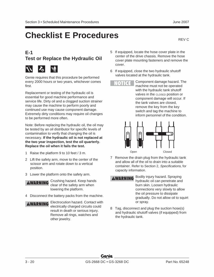
6 If equipped, close the two hydraulic shutoffvalves located at the hydraulic tank.
Component damage hazard. Themachine must not be operatedwith the hydraulic tank shutoffvalves in the CLOSED position orcomponent damage will occur. Ifthe tank valves are closed,remove the key from the keyswitch and tag the machine toinform personnel of the condition.
7 Remove the drain plug from the hydraulic tankand allow all of the oil to drain into a suitablecontainer. Refer to Section 2, Specifications, forcapacity information.
Bodily injury hazard. Sprayinghydraulic oil can penetrate andburn skin. Loosen hydraulicconnections very slowly to allowthe oil pressure to dissipategradually. Do not allow oil to squirtor spray.
8 Tag, disconnect and plug the suction hose(s)and hydraulic shutoff valves (if equipped) fromthe hydraulic tank.
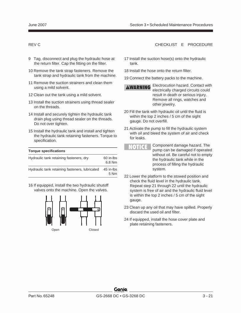
REV C
Section 3 • Scheduled Maintenance ProceduresJune 2007
Part No. 65248 GS-2668 DC • GS-3268 DC 3 - 21
Open Closed
CHECKLIST E PROCEDURE
9 Tag, disconnect and plug the hydraulic hose atthe return filter. Cap the fitting on the filter.
10 Remove the tank strap fasteners. Remove thetank strap and hydraulic tank from the machine.
11 Remove the suction strainers and clean themusing a mild solvent.
12 Clean out the tank using a mild solvent.
13 Install the suction strainers using thread sealeron the threads.
14 Install and securely tighten the hydraulic tankdrain plug using thread sealer on the threads.Do not over tighten.
15 Install the hydraulic tank and install and tightenthe hydraulic tank retaining fasteners. Torque tospecification.
Torque specifications
Hydraulic tank retaining fasteners, dry 60 in-lbs6.8 Nm
Hydraulic tank retaining fasteners, lubricated 45 in-lbs5 Nm
16 If equipped, install the two hydraulic shutoffvalves onto the machine. Open the valves.
17 Install the suction hose(s) onto the hydraulictank.
18 Install the hose onto the return filter.
19 Connect the battery packs to the machine.
Electrocution hazard. Contact withelectrically charged circuits couldresult in death or serious injury.Remove all rings, watches andother jewelry.
20 Fill the tank with hydraulic oil until the fluid iswithin the top 2 inches / 5 cm of the sightgauge. Do not overfill.
21 Activate the pump to fill the hydraulic systemwith oil and bleed the system of air and checkfor leaks.
Component damage hazard. Thepump can be damaged if operatedwithout oil. Be careful not to emptythe hydraulic tank while in theprocess of filling the hydraulicsystem.
22 Lower the platform to the stowed position andcheck the fluid level in the hydraulic tank.Repeat step 21 through 22 until the hydraulicsystem is free of air and the hydraulic fluid levelis within the top 2 inches / 5 cm of the sightgauge.
23 Clean up any oil that may have spilled. Properlydiscard the used oil and filter.
24 If equipped, install the hose cover plate andplate retaining fasteners.
REV C
Section 3 • Scheduled Maintenance Procedures June 2007
3 - 22 GS-2668 DC • GS-3268 DC Part No. 65248
CHECKLIST E PROCEDURE
E-2Grease the Steer AxleWheel Bearings
Genie requires that this procedure be performedevery 2000 hours or two years, whichever comesfirst.
Maintaining the steer axle wheel bearings isessential for safe machine operation and servicelife. Operating the machine with loose or wornwheel bearings may cause an unsafe operatingcondition and continued use may result incomponent damage. Extremely wet or dirtyconditions or regular steam cleaning and pressurewashing of the machine may require that thisprocedure be performed more often.
1 Loosen the wheel lug nuts. Do not removethem.
2 Block the non-steer wheels, then center a liftingjack under the steer axle.
3 Raise the machine 6 inches / 15 cm and placeblocks under the drive chassis for support.
4 Remove the lug nuts. Remove the tire andwheel assembly.
5 Check for wheel bearing wear by attempting tomove the wheel hub side to side, then up anddown.
Result: There is no side to side or up and downmovement. Proceed to step 10.
Result: There is side to side or up and downmovement Proceed to step 6.
6 Remove the dust cap from the hub. Remove thecotter pin from the castle nut.
7 Tighten the castle nut to 35 ft-lbs / 47 Nm toseat the bearings.
8 Fully loosen the castle nut and re-tighten to8 ft-lbs / 11 Nm.
9 Check for wheel bearing wear by attempting tomove the wheel hub side to side, then up anddown.
Result: There is no side to side or up and downmovement. Proceed to step 11.
Result: There is side to side or up and downmovement. Proceed to step 11 and replace thewheel bearings with new ones.
Note: When replacing a wheel bearing, both theinner and outer bearings, including the pressed-inraces, must be replaced.
10 Remove the dust cap from the hub. Remove thecotter pin from the castle nut.
11 Remove the castle nut.
12 Pull the hub off of the spindle. The spindlewasher, thrust washer and outer bearingshould fall loose from the hub.
REV C
Section 3 • Scheduled Maintenance ProceduresJune 2007
Part No. 65248 GS-2668 DC • GS-3268 DC 3 - 23
CHECKLIST E PROCEDURE
13 Place the hub on a flat surface and gently prythe bearing seal out of the hub. Remove therear bearing.
14 Pack both bearings with clean, fresh grease.
15 Place the large inner bearing into the rear of thehub.
16 Install a new bearing grease seal into the hubby pressing it evenly into the hub until it is flush.
17 Slide the hub onto the yoke spindle.
Component damage hazard. Donot apply excessive force ordamage to the lip of the seal mayoccur.
18 Place the outer bearing into the hub.
19 Install the spindle washer, thrust washer andcastle nut.
20 Tighten the slotted nut to 35 ft-lbs / 47 Nm toseat the bearings.
21 Fully loosen the castle nut and re-tighten to8 ft-lbs / 11 Nm.
22 Install a new cotter pin. Bend the cotter pinto lock it in place.
Note: Always use a new cotter pin when installinga castle nut.
23 Install the dust cap.

Section 3 • Scheduled Maintenance Procedures June 2007
3 - 24 GS-2668 DC • GS-3268 DC Part No. 65248
This page intentionally left blank.
Section 4 • Repair ProceduresJune 2007
Part No. 65248 GS-2668 DC • GS-3268 DC 4 - 1
Repair Procedures
About This SectionMost of the procedures in this section should onlybe performed by a trained service professionalin a suitably equipped workshop. Select theappropriate repair procedure after troubleshootingthe problem.
Perform disassembly procedures to the pointwhere repairs can be completed. Then tore-assemble, perform the disassembly steps inreverse order.
Symbols Legend
Safety alert symbol—used to alertpersonnel to potential personalinjury hazards. Obey all safetymessages that follow this symbolto avoid possible injury or death.
Indicates an imminently hazardoussituation which, if not avoided, willresult in death or serious injury.
Indicates a potentially hazardoussituation which, if not avoided,could result in death or seriousinjury.
Indicates a potentially hazardoussituation which, if not avoided,may cause minor or moderateinjury.
Indicates a potentially hazardoussituation which, if not avoided,may result in property damage.
Indicates that a specific result is expected afterperforming a series of steps.
Indicates that an incorrect result has occurredafter performing a series of steps.
Observe and Obey:Repair procedures shall be completed by aperson trained and qualified on the repair of thismachine.
Immediately tag and remove from service adamaged or malfunctioning machine.
Repair any machine damage or malfunctionbefore operating the machine.
Before Repairs Start:Read, understand and obey the safety rulesand operating instructions in the appropriateoperator’s manual on your machine.
Be sure that all necessary tools and parts areavailable and ready for use.
Use only Genie approved replacement parts.
Read each procedure completely and adhereto the instructions. Attempting shortcuts mayproduce hazardous conditions.
Unless otherwise specified, perform each repairprocedure with the machine in the followingconfiguration:
· Machine parked on a firm, level surface
· Platform in the stowed position
· Key switch in the off position with the keyremoved
· The red Emergency Stop button in the offposition at both ground and platform controls
· Wheels chocked
· All external AC power supply disconnectedfrom the machine
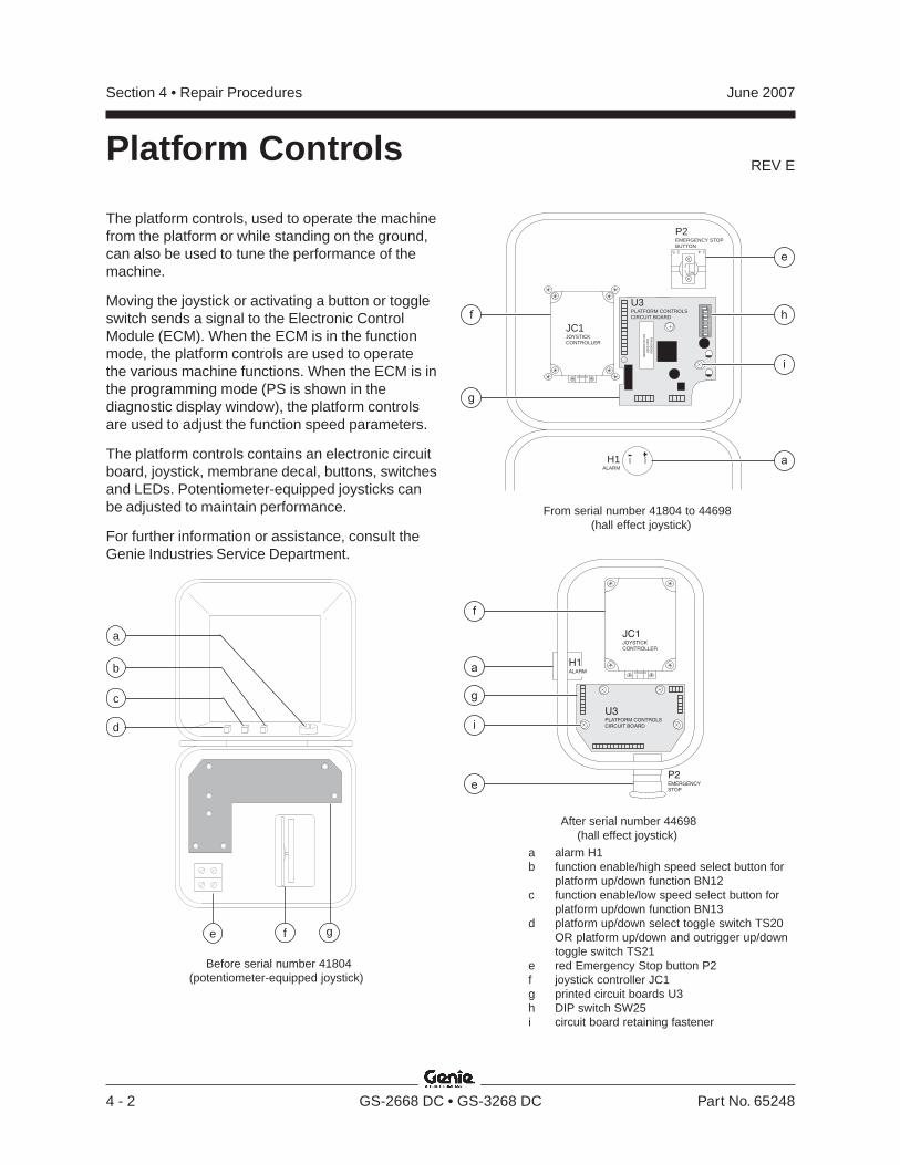
REV E
Section 4 • Repair Procedures June 2007
4 - 2 GS-2668 DC • GS-3268 DC Part No. 65248
e
a
f
i
JC1JOYSTICKCONTROLLER
U3PLATFORM CONTROLSCIRCUIT BOARD
P2EMERGENCYSTOP
H1ALARM
g
After serial number 44698 (hall effect joystick)
Platform Controls
Before serial number 41804 (potentiometer-equipped joystick)
The platform controls, used to operate the machinefrom the platform or while standing on the ground,can also be used to tune the performance of themachine.
Moving the joystick or activating a button or toggleswitch sends a signal to the Electronic ControlModule (ECM). When the ECM is in the functionmode, the platform controls are used to operatethe various machine functions. When the ECM is inthe programming mode (PS is shown in thediagnostic display window), the platform controlsare used to adjust the function speed parameters.
The platform controls contains an electronic circuitboard, joystick, membrane decal, buttons, switchesand LEDs. Potentiometer-equipped joysticks canbe adjusted to maintain performance.
For further information or assistance, consult theGenie Industries Service Department.
From serial number 41804 to 44698 (hall effect joystick)
e f g
a
c
b
d
P2EMERGENCY STOPBUTTON
H1ALARM
U3PLATFORM CONTROLSCIRCUIT BOARD
1 4.2 5.
2
1 NC
19F
23
45
67
8
ON
ALCOADF085
P/N
000000D
ate 0000S
/N A
l 00000000
JC1JOYSTICKCONTROLLER
h
e
i
a
f
g
a alarm H1b function enable/high speed select button for
platform up/down function BN12c function enable/low speed select button for
platform up/down function BN13d platform up/down select toggle switch TS20
OR platform up/down and outrigger up/downtoggle switch TS21
e red Emergency Stop button P2f joystick controller JC1g printed circuit boards U3h DIP switch SW25i circuit board retaining fastener
REV E
Section 4 • Repair ProceduresJune 2007
Part No. 65248 GS-2668 DC • GS-3268 DC 4 - 3
1-1Circuit Boards
How to Remove the PlatformControls Circuit Board1 Turn the key switch to the off position and push
in the red Emergency Stop button to the offposition at both the ground and platformcontrols.
2 Loosen or remove the fasteners securing theplatform control box together. Open the controlbox.
3 Locate the circuit board mounted to the top halfof the platform control box.
Electrocution hazard. Contact withelectrically charged circuits couldresult in death or serious injury.Remove all rings, watches andother jewelry.
Component damage hazard.Electrostatic discharge (ESD) candamage printed circuit boardcomponents. Maintain firm contactwith a metal part of the machinethat is grounded at all times whenhandling printed circuit boards ORuse a grounded wrist strap.
4 Carefully disconnect the wire harnessconnectors from the circuit board.
5 Models with Generation 5 platform controls:Remove the alarm and the red Emergency Stopbutton.
6 Carefully remove the circuit board retainingfasteners and remove the circuit board from thecontrol box.
1-2Joystick Controller
Maintaining the joystick at the proper setting isessential to safe machine operation. The joystickshould operate smoothly over its entire range ofmotion.
A Hall-effect joystick controller was incorporatedinto the platform controls after serial number41803. It does not require any calibration.
How to Calibrate the JoystickControllerNote: This procedure applies only to models with apotentiometer-equipped joystick.
Note: If the joystick is out of calibration on modelsbefore serial number 41200, code 30 will bepresent on the diagnostic display and the errorindicator light will be on at the platform controls.If the joystick is out of calibration on models afterserial number 41199, code 47 will be present onthe diagnostic display and the error indicator lightwill be on at the platform controls.
Before serial number 41804:
1 Turn the key switch to platform control and pullout the red Emergency Stop button to the ON
position at both the ground and platformcontrols.
2 Remove the platform control box lid retainingfasteners. Open the control box lid.
Electrocution hazard. Contact withelectrically charged circuits couldresult in death or serious injury.Remove all rings, watches andother jewelry.
PLATFORM CONTROLS

REV E
Section 4 • Repair Procedures June 2007
4 - 4 GS-2668 DC • GS-3268 DC Part No. 65248
PLATFORM CONTROLS
3 Locate the potentiometer on the base of thejoystick.
a joystick controller JC1b potentiometer shaft slotc potentiometer shaft set screwd platform controls circuit board U3e potentiometer R15f brown wireg purple wire
4 Using a volt meter set to read DC voltage, placethe volt meter negative lead on the purple wire.Place the volt meter positive lead on the brownwire.
Electrocution hazard. Contact withelectrically charged circuits couldresult in death or serious injury.Remove all rings, watches andother jewelry.
5 Loosen the set screw on the potentiometershaft just enough to allow the shaft to rotate.
6 With the joystick in the center position, adjustthe potentiometer shaft until 2.05V DC isdisplayed on the volt meter. Tighten the setscrew.
7 Do not hold the function enable switch.
8 Move the joystick full stroke in both directionsseveral times. Return the joystick to the centerposition.
Result: The volt meter should read 2.05V DC.
Result: If the volt meter does not read2.05V DC, repeat steps 5 through 8.
9 Turn the key switch to the off position and waita few seconds.
10 Turn the key switch to platform control.
Result: The error indicator light on the top of theplatform control box should go out and code 30should not be present on the diagnostic display.
Result: If the error indicator light is still on or ifcode 30 is present on the diagnostic display,repeat steps 5 through 8.
11 Turn the key switch to the off position.
12 Close the lid and tighten the fasteners.
CONTROLLERJOYSTICK
JC1
U3PLATFORMCONTROLSCIRCUITBOARD
a
b
c
g
f
e
d1 2 3 4 5 6 7 8
ON DIP
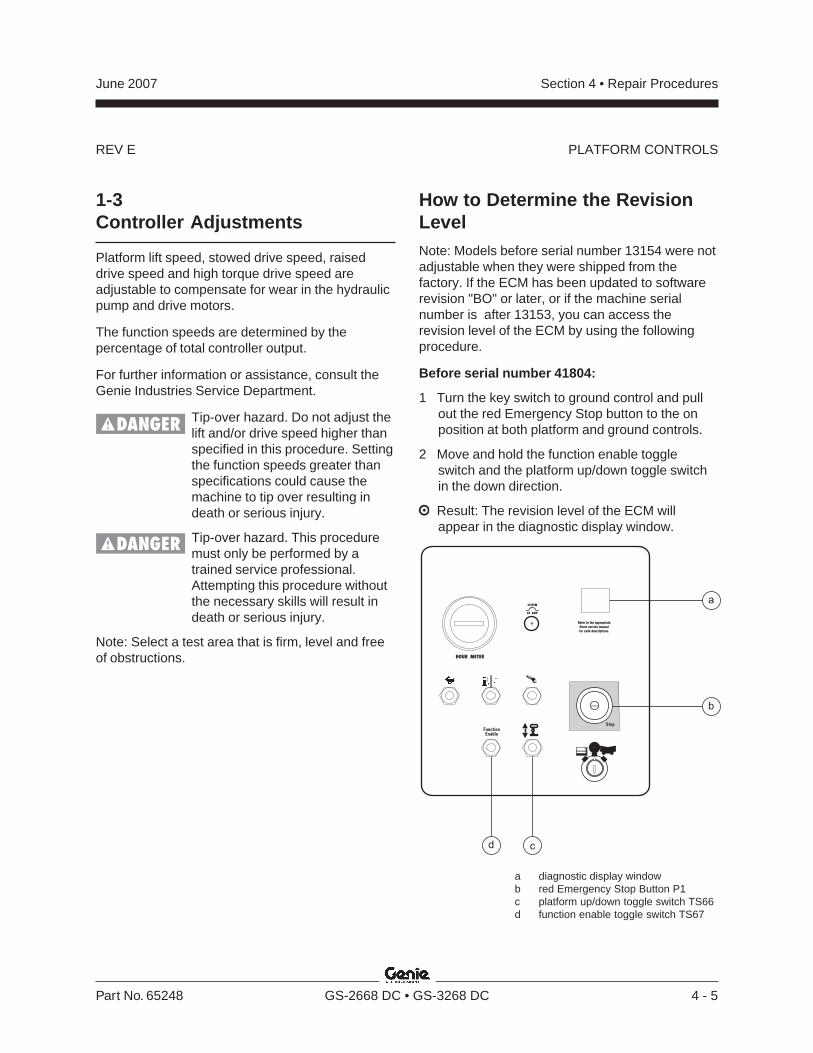
REV E
Section 4 • Repair ProceduresJune 2007
Part No. 65248 GS-2668 DC • GS-3268 DC 4 - 5
1-3Controller Adjustments
Platform lift speed, stowed drive speed, raiseddrive speed and high torque drive speed areadjustable to compensate for wear in the hydraulicpump and drive motors.
The function speeds are determined by thepercentage of total controller output.
For further information or assistance, consult theGenie Industries Service Department.
Tip-over hazard. Do not adjust thelift and/or drive speed higher thanspecified in this procedure. Settingthe function speeds greater thanspecifications could cause themachine to tip over resulting indeath or serious injury.
Tip-over hazard. This proceduremust only be performed by atrained service professional.Attempting this procedure withoutthe necessary skills will result indeath or serious injury.
Note: Select a test area that is firm, level and freeof obstructions.
How to Determine the RevisionLevelNote: Models before serial number 13154 were notadjustable when they were shipped from thefactory. If the ECM has been updated to softwarerevision "BO" or later, or if the machine serialnumber is after 13153, you can access therevision level of the ECM by using the followingprocedure.
Before serial number 41804:
1 Turn the key switch to ground control and pullout the red Emergency Stop button to the onposition at both platform and ground controls.
2 Move and hold the function enable toggleswitch and the platform up/down toggle switchin the down direction.
Result: The revision level of the ECM willappear in the diagnostic display window.
PLATFORM CONTROLS
a diagnostic display windowb red Emergency Stop Button P1c platform up/down toggle switch TS66d function enable toggle switch TS67
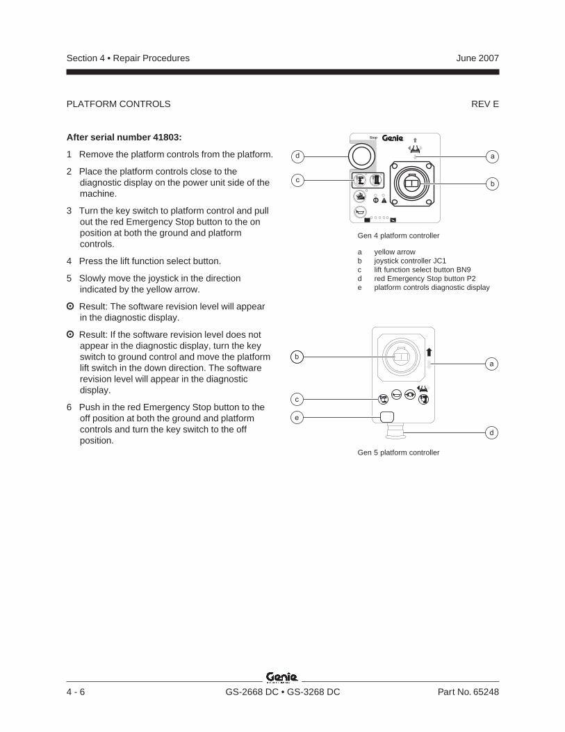
REV E
Section 4 • Repair Procedures June 2007
4 - 6 GS-2668 DC • GS-3268 DC Part No. 65248
PLATFORM CONTROLS
After serial number 41803:
1 Remove the platform controls from the platform.
2 Place the platform controls close to thediagnostic display on the power unit side of themachine.
3 Turn the key switch to platform control and pullout the red Emergency Stop button to the onposition at both the ground and platformcontrols.
4 Press the lift function select button.
5 Slowly move the joystick in the directionindicated by the yellow arrow.
Result: The software revision level will appearin the diagnostic display.
Result: If the software revision level does notappear in the diagnostic display, turn the keyswitch to ground control and move the platformlift switch in the down direction. The softwarerevision level will appear in the diagnosticdisplay.
6 Push in the red Emergency Stop button to theoff position at both the ground and platformcontrols and turn the key switch to the offposition.
®
Stop
d
c
a
b
a
d
b
c
e
Gen 4 platform controller
a yellow arrowb joystick controller JC1c lift function select button BN9d red Emergency Stop button P2e platform controls diagnostic display
Gen 5 platform controller
REV E
Section 4 • Repair ProceduresJune 2007
Part No. 65248 GS-2668 DC • GS-3268 DC 4 - 7
How to Adjust the Fast Lift Speed(before serial number 41200)
1 Remove the platform controls from the platformand place the controls near the diagnosticdisplay at the ground control panel.
2 Turn the key switch to the off position.
3 Press and hold the platform extend/retractenable button or outrigger enable button andturn the key switch to platform controls.
Result: The diagnostic display will show "PS."
4 Release the horn button and the platformextend/retract enable button or outrigger enablebutton.
Result: The diagnostic display will show themaximum lift speed percentage.
5 Press and hold the function enable/high speedselect button to show the fast platform lift speedpercentage in the diagnostic display window.
6 To increase or decrease the fast platform liftspeed, press and hold the function enable/highspeed select button while using the steeringrocker switch to adjust the percentage. Thepercentage will be seen in the diagnosticdisplay window.
7 Release the function enable/high speed selectbutton.
8 Turn the key switch to the off position to savethe settings.
Note: Any change in software settings will not takeeffect until the key switch is turned to the offposition.
9 Confirm the lift speed of the machine. Refer toSection 2, Specifications.
How to Adjust the Slow LiftSpeed (before serial number 41200)
1 Remove the platform controls from the platformand place the controls near the diagnosticdisplay at the ground control panel.
2 Turn the key switch to the off position.
3 Press and hold the platform extend/retractenable button or outrigger enable button andturn the key switch to platform controls.
Result: The diagnostic display will show "PS."
4 Release the horn button and the platformextend/retract enable button or outrigger enablebutton.
Result: The diagnostic display will show themaximum lift speed percentage.
5 Press and hold the function enable/low speedselect button to show the slow platform liftspeed percentage in the diagnostic displaywindow.
6 To increase or decrease the platform lift speed,press and hold the function enable/low speedselect button while using the steering rockerswitch to adjust the percentage. Thepercentage will be seen in the diagnosticdisplay window.
7 Release the function enable/low speed selectbutton.
8 Turn the key switch to the off position to savethe settings.
Note: Any change in software settings will not takeeffect until the key switch is turned to the offposition.
9 Confirm the lift speed of the machine. Refer toSection 2, Specifications.
PLATFORM CONTROLS
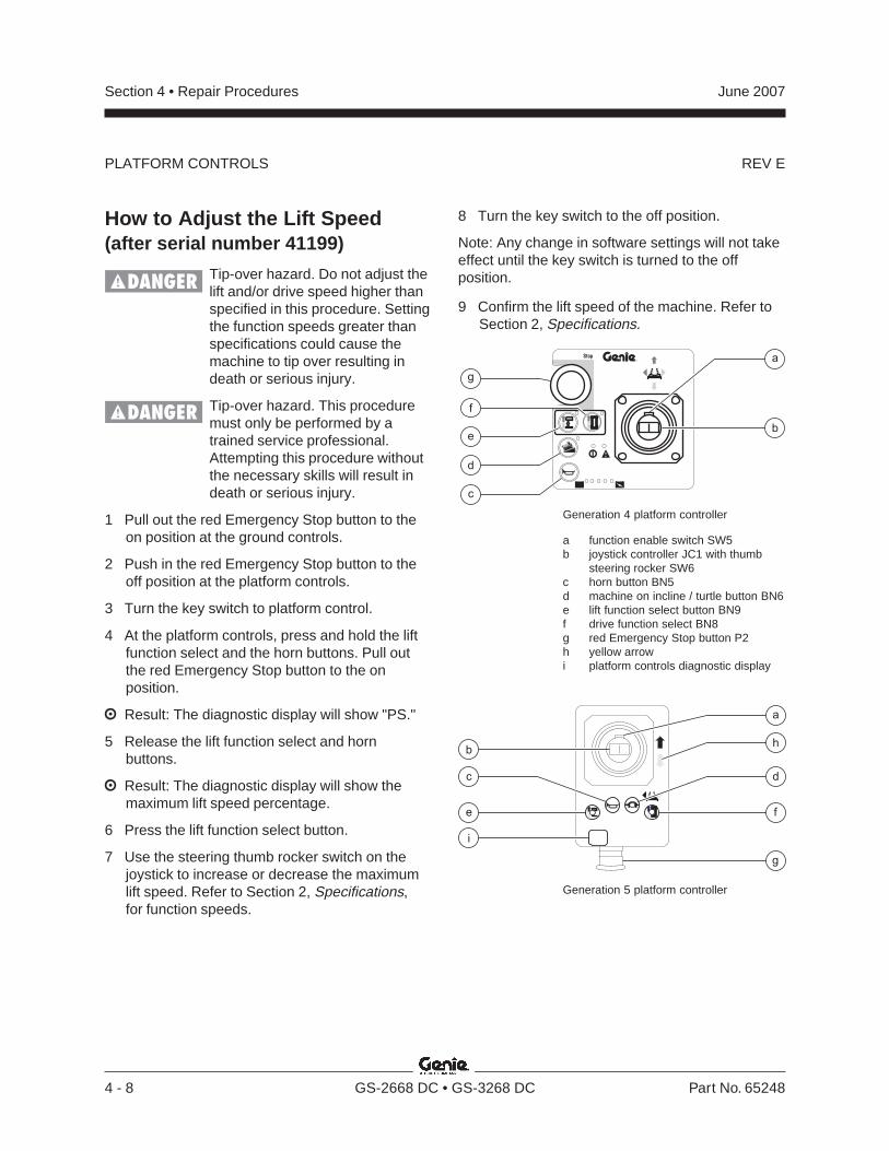
REV E
Section 4 • Repair Procedures June 2007
4 - 8 GS-2668 DC • GS-3268 DC Part No. 65248
How to Adjust the Lift Speed(after serial number 41199)
Tip-over hazard. Do not adjust thelift and/or drive speed higher thanspecified in this procedure. Settingthe function speeds greater thanspecifications could cause themachine to tip over resulting indeath or serious injury.
Tip-over hazard. This proceduremust only be performed by atrained service professional.Attempting this procedure withoutthe necessary skills will result indeath or serious injury.
1 Pull out the red Emergency Stop button to theon position at the ground controls.
2 Push in the red Emergency Stop button to theoff position at the platform controls.
3 Turn the key switch to platform control.
4 At the platform controls, press and hold the liftfunction select and the horn buttons. Pull outthe red Emergency Stop button to the onposition.
Result: The diagnostic display will show "PS."
5 Release the lift function select and hornbuttons.
Result: The diagnostic display will show themaximum lift speed percentage.
6 Press the lift function select button.
7 Use the steering thumb rocker switch on thejoystick to increase or decrease the maximumlift speed. Refer to Section 2, Specifications,for function speeds.
Generation 4 platform controller
a function enable switch SW5b joystick controller JC1 with thumb
steering rocker SW6c horn button BN5d machine on incline / turtle button BN6e lift function select button BN9f drive function select BN8g red Emergency Stop button P2h yellow arrowi platform controls diagnostic display
PLATFORM CONTROLS
Generation 5 platform controller
b
fe
c
i
d
h
g
a
8 Turn the key switch to the off position.
Note: Any change in software settings will not takeeffect until the key switch is turned to the offposition.
9 Confirm the lift speed of the machine. Refer toSection 2, Specifications.
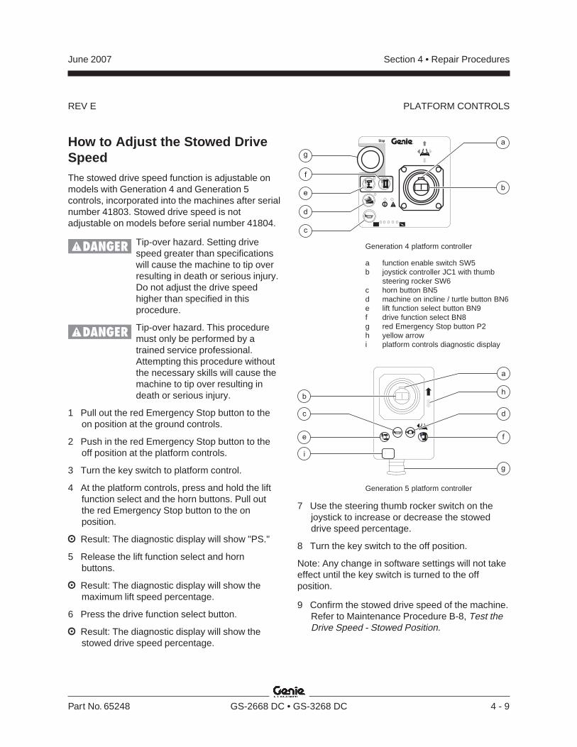
REV E
Section 4 • Repair ProceduresJune 2007
Part No. 65248 GS-2668 DC • GS-3268 DC 4 - 9
PLATFORM CONTROLS
How to Adjust the Stowed DriveSpeedThe stowed drive speed function is adjustable onmodels with Generation 4 and Generation 5controls, incorporated into the machines after serialnumber 41803. Stowed drive speed is notadjustable on models before serial number 41804.
Tip-over hazard. Setting drivespeed greater than specificationswill cause the machine to tip overresulting in death or serious injury.Do not adjust the drive speedhigher than specified in thisprocedure.
Tip-over hazard. This proceduremust only be performed by atrained service professional.Attempting this procedure withoutthe necessary skills will cause themachine to tip over resulting indeath or serious injury.
1 Pull out the red Emergency Stop button to theon position at the ground controls.
2 Push in the red Emergency Stop button to theoff position at the platform controls.
3 Turn the key switch to platform control.
4 At the platform controls, press and hold the liftfunction select and the horn buttons. Pull outthe red Emergency Stop button to the onposition.
Result: The diagnostic display will show "PS."
5 Release the lift function select and hornbuttons.
Result: The diagnostic display will show themaximum lift speed percentage.
6 Press the drive function select button.
Result: The diagnostic display will show thestowed drive speed percentage.
Generation 4 platform controller
a function enable switch SW5b joystick controller JC1 with thumb
steering rocker SW6c horn button BN5d machine on incline / turtle button BN6e lift function select button BN9f drive function select BN8g red Emergency Stop button P2h yellow arrowi platform controls diagnostic display
Generation 5 platform controller
7 Use the steering thumb rocker switch on thejoystick to increase or decrease the stoweddrive speed percentage.
8 Turn the key switch to the off position.
Note: Any change in software settings will not takeeffect until the key switch is turned to the offposition.
9 Confirm the stowed drive speed of the machine.Refer to Maintenance Procedure B-8, Test theDrive Speed - Stowed Position.
b
fe
c
i
d
h
g
a
REV E
Section 4 • Repair Procedures June 2007
4 - 10 GS-2668 DC • GS-3268 DC Part No. 65248
How to Adjust the Raised DriveSpeed
Tip-over hazard. Setting drivespeed greater than specificationswill cause the machine to tip overresulting in death or serious injury.Do not adjust the drive speedhigher than specified in thisprocedure.
Tip-over hazard. This proceduremust only be performed by atrained service professional.Attempting this procedure withoutthe necessary skills will result indeath or serious injury.
Note: The drive function of the GS-2668 DC beforeserial number 26563 is disabled when the platformis 20 feet / 6.1 m or higher while the platform isextended. The GS-2668 DC after serial number26562 is able to drive at full height due toadditional counterweight being added to themachine.
Note: The drive function of the GS-3268 DC beforeserial number 41200 is disabled when the platformis 26 feet / 7.9 m or higher while the platform isextended. The GS-3268 DC after serial number41199 is able to drive at full height due toadditional counterweight being added to themachine.
Before serial number 41200:
1 Remove the platform controls from the platformand place the controls near the diagnosticdisplay window at the ground control panel.
2 Turn the key switch to the off position.
3 Press and hold the platform extend/retractenable button or outrigger enable button andturn the key switch to platform controls.
Result: The diagnostic display will show "PS."
4 Release the horn button and the platformextend/retract enable button or outrigger enablebutton.
Result: The diagnostic display will show themaximum lift speed percentage.
5 Press the horn button to show the maximumraised drive speed percentage.
6 To increase or decrease the raised drive speed,press and hold the horn button while using thesteering rocker switch to adjust the percentage.The percentage will be seen in the diagnosticdisplay window.
7 Release the horn button.
8 Turn the key switch to the off position to savethe settings.
Note: Any change in software settings will not takeeffect until the key switch is turned to the offposition.
9 Confirm the raised drive speed of the machine.Refer to Maintenance Procedure B-9, Test theDrive Speed - Raised Position.
PLATFORM CONTROLS
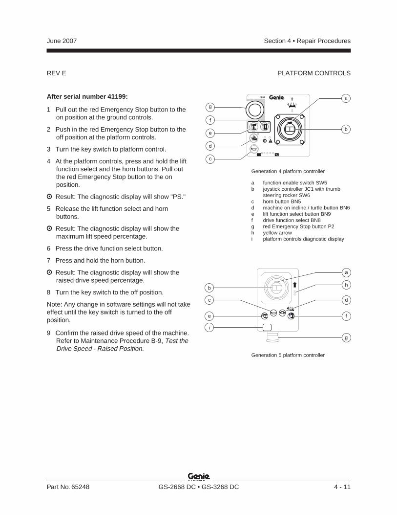
REV E
Section 4 • Repair ProceduresJune 2007
Part No. 65248 GS-2668 DC • GS-3268 DC 4 - 11
After serial number 41199:
1 Pull out the red Emergency Stop button to theon position at the ground controls.
2 Push in the red Emergency Stop button to theoff position at the platform controls.
3 Turn the key switch to platform control.
4 At the platform controls, press and hold the liftfunction select and the horn buttons. Pull outthe red Emergency Stop button to the onposition.
Result: The diagnostic display will show "PS."
5 Release the lift function select and hornbuttons.
Result: The diagnostic display will show themaximum lift speed percentage.
6 Press the drive function select button.
7 Press and hold the horn button.
Result: The diagnostic display will show theraised drive speed percentage.
8 Turn the key switch to the off position.
Note: Any change in software settings will not takeeffect until the key switch is turned to the offposition.
9 Confirm the raised drive speed of the machine.Refer to Maintenance Procedure B-9, Test theDrive Speed - Raised Position.
PLATFORM CONTROLS
b
fe
c
i
d
h
g
a
Generation 4 platform controller
a function enable switch SW5b joystick controller JC1 with thumb
steering rocker SW6c horn button BN5d machine on incline / turtle button BN6e lift function select button BN9f drive function select BN8g red Emergency Stop button P2h yellow arrowi platform controls diagnostic display
Generation 5 platform controller
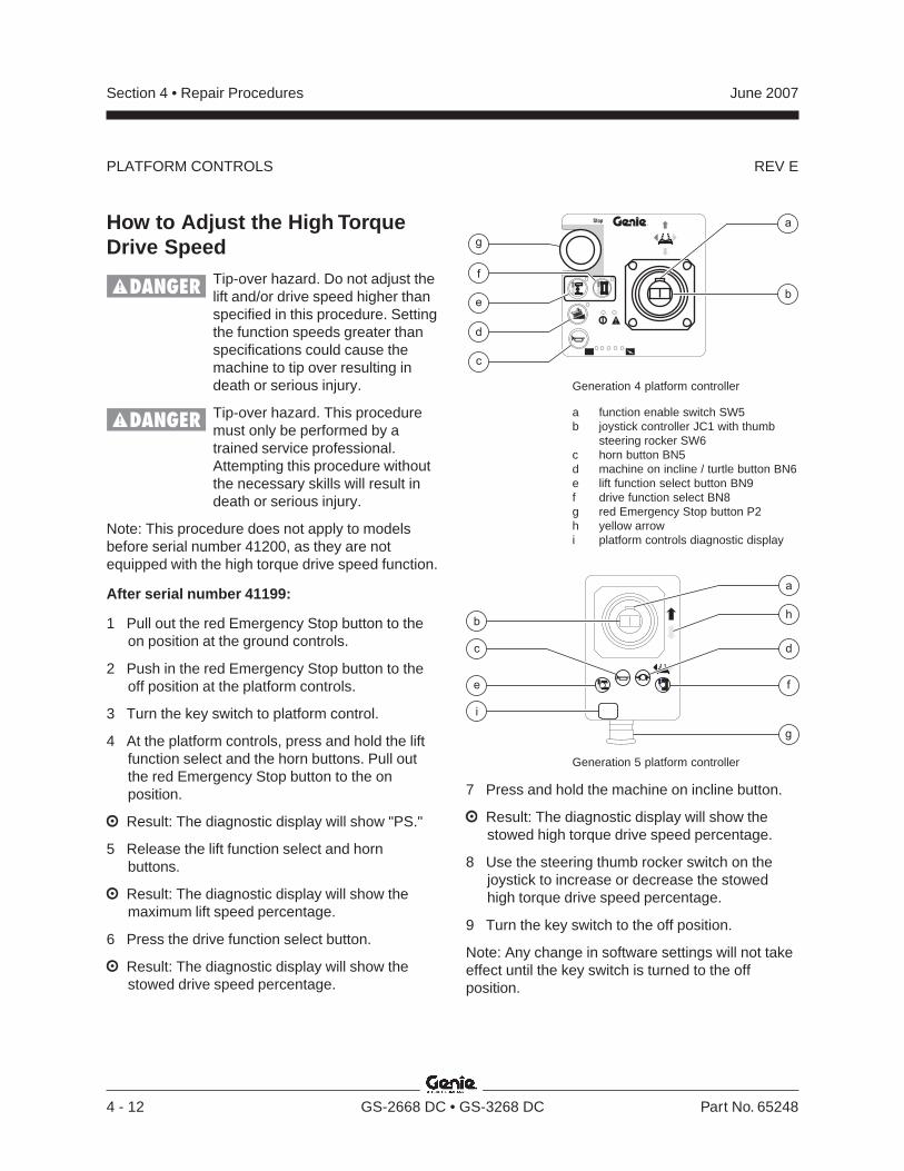
REV E
Section 4 • Repair Procedures June 2007
4 - 12 GS-2668 DC • GS-3268 DC Part No. 65248
PLATFORM CONTROLS
b
fe
c
i
d
h
g
a
How to Adjust the High TorqueDrive Speed
Tip-over hazard. Do not adjust thelift and/or drive speed higher thanspecified in this procedure. Settingthe function speeds greater thanspecifications could cause themachine to tip over resulting indeath or serious injury.
Tip-over hazard. This proceduremust only be performed by atrained service professional.Attempting this procedure withoutthe necessary skills will result indeath or serious injury.
Note: This procedure does not apply to modelsbefore serial number 41200, as they are notequipped with the high torque drive speed function.
After serial number 41199:
1 Pull out the red Emergency Stop button to theon position at the ground controls.
2 Push in the red Emergency Stop button to theoff position at the platform controls.
3 Turn the key switch to platform control.
4 At the platform controls, press and hold the liftfunction select and the horn buttons. Pull outthe red Emergency Stop button to the onposition.
Result: The diagnostic display will show "PS."
5 Release the lift function select and hornbuttons.
Result: The diagnostic display will show themaximum lift speed percentage.
6 Press the drive function select button.
Result: The diagnostic display will show thestowed drive speed percentage.
Generation 4 platform controller
a function enable switch SW5b joystick controller JC1 with thumb
steering rocker SW6c horn button BN5d machine on incline / turtle button BN6e lift function select button BN9f drive function select BN8g red Emergency Stop button P2h yellow arrowi platform controls diagnostic display
Generation 5 platform controller
7 Press and hold the machine on incline button.
Result: The diagnostic display will show thestowed high torque drive speed percentage.
8 Use the steering thumb rocker switch on thejoystick to increase or decrease the stowedhigh torque drive speed percentage.
9 Turn the key switch to the off position.
Note: Any change in software settings will not takeeffect until the key switch is turned to the offposition.
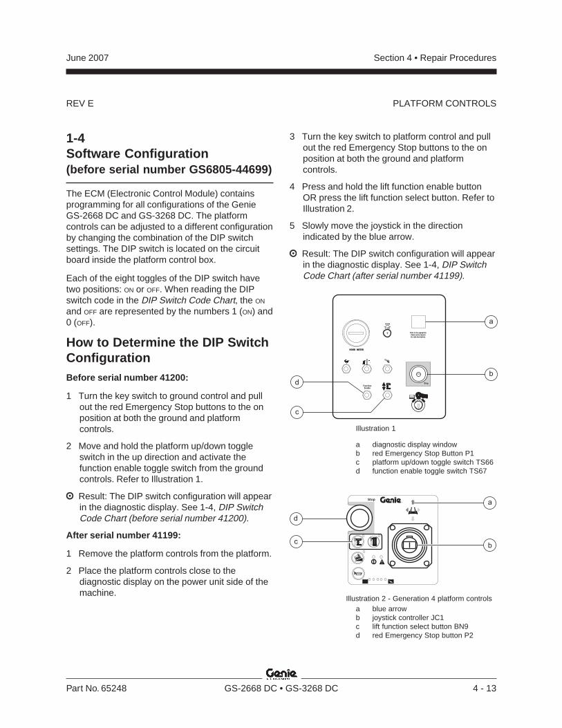
REV E
Section 4 • Repair ProceduresJune 2007
Part No. 65248 GS-2668 DC • GS-3268 DC 4 - 13
PLATFORM CONTROLS
1-4Software Configuration(before serial number GS6805-44699)
The ECM (Electronic Control Module) containsprogramming for all configurations of the GenieGS-2668 DC and GS-3268 DC. The platformcontrols can be adjusted to a different configurationby changing the combination of the DIP switchsettings. The DIP switch is located on the circuitboard inside the platform control box.
Each of the eight toggles of the DIP switch havetwo positions: ON or OFF. When reading the DIPswitch code in the DIP Switch Code Chart, the ON
and OFF are represented by the numbers 1 (ON) and0 (OFF).
How to Determine the DIP SwitchConfigurationBefore serial number 41200:
1 Turn the key switch to ground control and pullout the red Emergency Stop buttons to the onposition at both the ground and platformcontrols.
2 Move and hold the platform up/down toggleswitch in the up direction and activate thefunction enable toggle switch from the groundcontrols. Refer to Illustration 1.
Result: The DIP switch configuration will appearin the diagnostic display. See 1-4, DIP SwitchCode Chart (before serial number 41200).
After serial number 41199:
1 Remove the platform controls from the platform.
2 Place the platform controls close to thediagnostic display on the power unit side of themachine.
20 AMP
SYSTEM
HOUR METER
Refer to the appropriate
Genie service manual
for code descriptions.
FunctionEnable
Stop
b
a
d
c
3 Turn the key switch to platform control and pullout the red Emergency Stop buttons to the onposition at both the ground and platformcontrols.
4 Press and hold the lift function enable buttonOR press the lift function select button. Refer toIllustration 2.
5 Slowly move the joystick in the directionindicated by the blue arrow.
Result: The DIP switch configuration will appearin the diagnostic display. See 1-4, DIP SwitchCode Chart (after serial number 41199).
Illustration 1
a diagnostic display windowb red Emergency Stop Button P1c platform up/down toggle switch TS66d function enable toggle switch TS67
Illustration 2 - Generation 4 platform controlsa blue arrowb joystick controller JC1c lift function select button BN9d red Emergency Stop button P2
®
Stop
d
c
a
b
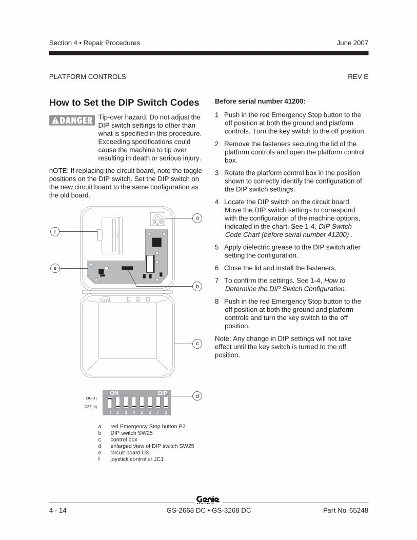
REV E
Section 4 • Repair Procedures June 2007
4 - 14 GS-2668 DC • GS-3268 DC Part No. 65248
PLATFORM CONTROLS
b
f
e
a
c
dON (1)
1 2 3 4 5 6 7 8
ON DIP
OFF (0)
How to Set the DIP Switch CodesTip-over hazard. Do not adjust theDIP switch settings to other thanwhat is specified in this procedure.Exceeding specifications couldcause the machine to tip overresulting in death or serious injury.
nOTE: If replacing the circuit board, note the togglepositions on the DIP switch. Set the DIP switch onthe new circuit board to the same configuration asthe old board.
a red Emergency Stop button P2b DIP switch SW25c control boxd enlarged view of DIP switch SW25e circuit board U3f joystick controller JC1
Before serial number 41200:
1 Push in the red Emergency Stop button to theoff position at both the ground and platformcontrols. Turn the key switch to the off position.
2 Remove the fasteners securing the lid of theplatform controls and open the platform controlbox.
3 Rotate the platform control box in the positionshown to correctly identify the configuration ofthe DIP switch settings.
4 Locate the DIP switch on the circuit board.Move the DIP switch settings to correspondwith the configuration of the machine options,indicated in the chart. See 1-4, DIP SwitchCode Chart (before serial number 41200) .
5 Apply dielectric grease to the DIP switch aftersetting the configuration.
6 Close the lid and install the fasteners.
7 To confirm the settings. See 1-4, How toDetermine the DIP Switch Configuration.
8 Push in the red Emergency Stop button to theoff position at both the ground and platformcontrols and turn the key switch to the offposition.
Note: Any change in DIP settings will not takeeffect until the key switch is turned to the offposition.
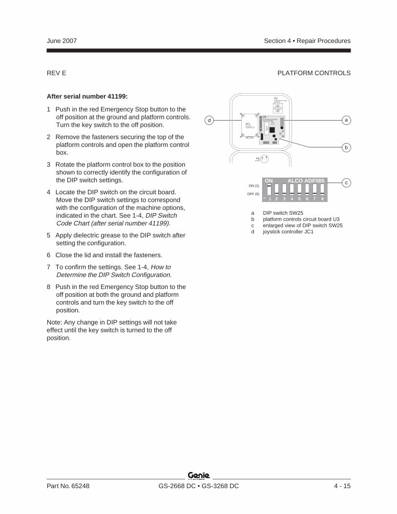
REV E
Section 4 • Repair ProceduresJune 2007
Part No. 65248 GS-2668 DC • GS-3268 DC 4 - 15
PLATFORM CONTROLS
cON (1)
OFF (0)
19F 2 3 4 5 6 7 8
ON ALCO ADF085
P2EMERGENCY STOPBUTTON
H1ALARM
U3PLATFORM CONTROLSCIRCUIT BOARD
1 4.2 5.
2
1 NC
19F
23
45
67
8
ON
AL
CO
AD
F085
P/N
000000D
ate 0000S
/N A
l 00000000
JC1JOYSTICKCONTROLLER
a
b
d
After serial number 41199:
1 Push in the red Emergency Stop button to theoff position at the ground and platform controls.Turn the key switch to the off position.
2 Remove the fasteners securing the top of theplatform controls and open the platform controlbox.
3 Rotate the platform control box to the positionshown to correctly identify the configuration ofthe DIP switch settings.
4 Locate the DIP switch on the circuit board.Move the DIP switch settings to correspondwith the configuration of the machine options,indicated in the chart. See 1-4, DIP SwitchCode Chart (after serial number 41199).
5 Apply dielectric grease to the DIP switch aftersetting the configuration.
6 Close the lid and install the fasteners.
7 To confirm the settings. See 1-4, How toDetermine the DIP Switch Configuration.
8 Push in the red Emergency Stop button to theoff position at both the ground and platformcontrols and turn the key switch to the offposition.
Note: Any change in DIP settings will not takeeffect until the key switch is turned to the offposition.
a DIP switch SW25b platform controls circuit board U3c enlarged view of DIP switch SW25d joystick controller JC1
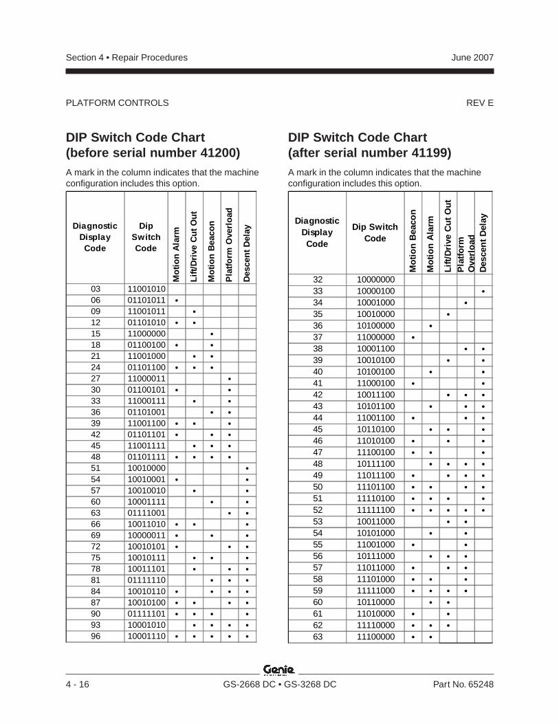
REV E
Section 4 • Repair Procedures June 2007
4 - 16 GS-2668 DC • GS-3268 DC Part No. 65248
PLATFORM CONTROLS
Diagnostic Display Code
Dip Switch Code
Mo
tio
n A
larm
Lif
t/D
rive
Cu
t O
ut
Mo
tio
n B
eaco
n
Pla
tfo
rm O
verl
oad
Des
cen
t D
elay
03 1100101006 01101011 •09 11001011 •12 01101010 • •15 11000000 •18 01100100 • •21 11001000 • •24 01101100 • • •27 11000011 •30 01100101 • •33 11000111 • •36 01101001 • •39 11001100 • • •42 01101101 • • •45 11001111 • • •48 01101111 • • • •51 10010000 •54 10010001 • •57 10010010 • •60 10001111 • •63 01111001 • •66 10011010 • • •69 10000011 • • •72 10010101 • • •75 10010111 • • •78 10011101 • • •81 01111110 • • •84 10010110 • • • •87 10010100 • • • •90 01111101 • • • •93 10001010 • • • •96 10001110 • • • • •
Diagnostic Display Code
Dip Switch Code
Mo
tio
n B
eaco
n
Mo
tio
n A
larm
Lif
t/D
rive
Cu
t O
ut
Pla
tfo
rm
Ove
rlo
adD
esce
nt
Del
ay
32 1000000033 10000100 •34 10001000 •35 10010000 •36 10100000 •37 11000000 •38 10001100 • •39 10010100 • •40 10100100 • •41 11000100 • •42 10011100 • • •43 10101100 • • •44 11001100 • • •45 10110100 • • •46 11010100 • • •47 11100100 • • •48 10111100 • • • •49 11011100 • • • •50 11101100 • • • •51 11110100 • • • •52 11111100 • • • • •53 10011000 • •54 10101000 • •55 11001000 • •56 10111000 • • •57 11011000 • • •58 11101000 • • •59 11111000 • • • •60 10110000 • •61 11010000 • •62 11110000 • • •63 11100000 • •
DIP Switch Code Chart(before serial number 41200)A mark in the column indicates that the machineconfiguration includes this option.
DIP Switch Code Chart(after serial number 41199)A mark in the column indicates that the machineconfiguration includes this option.
REV E
Section 4 • Repair ProceduresJune 2007
Part No. 65248 GS-2668 DC • GS-3268 DC 4 - 17
PLATFORM CONTROLS
DIP Switch Function DefinitionsNote: If replacing the circuit board, note the togglepositions on the DIP switches. Set the DIPswitches on the new circuit board to the sameconfiguration of the old board.
Motion Beacon: The motion beacon optionflashes only when operating a function.
Motion Alarm: The motion alarm will sound whenoperating any function.
Lift/Drive Cut Out: This cuts out lift and drivefunctions when the machine exceeds the rating onthe serial plate. Required for Europe and Australiabefore serial number 41126. Installed on allmachines after serial number 41125.
Platform Overload: This cuts out all functionswhen the pressure sensor is overloaded. The redEmergency Stop button must be cycled before anyfunction can be resumed. Required for CE models.
Descent Delay: This option halts descent atapproximately 7 feet / 2.1 m. All controls must bereleased for 4 to 6 seconds before descent isre-enabled. Required for CE models.
Battery Drain Alarm: When the machine is turnedon and no function is activated for 10 minutes, thealarm will sound once every 3 seconds. This optioncan be activated by moving DIP switch 7 toposition 1.
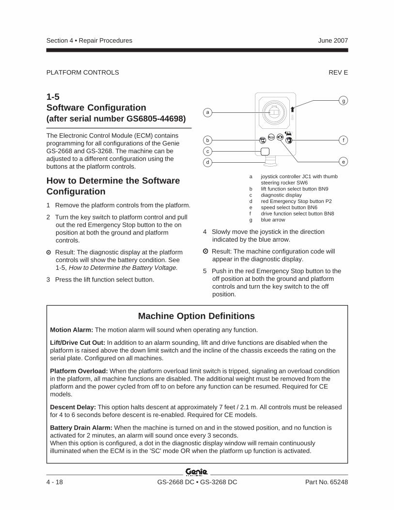
REV E
Section 4 • Repair Procedures June 2007
4 - 18 GS-2668 DC • GS-3268 DC Part No. 65248
PLATFORM CONTROLS
1-5Software Configuration(after serial number GS6805-44698)
The Electronic Control Module (ECM) containsprogramming for all configurations of the GenieGS-2668 and GS-3268. The machine can beadjusted to a different configuration using thebuttons at the platform controls.
How to Determine the SoftwareConfiguration1 Remove the platform controls from the platform.
2 Turn the key switch to platform control and pullout the red Emergency Stop button to the onposition at both the ground and platformcontrols.
Result: The diagnostic display at the platformcontrols will show the battery condition. See1-5, How to Determine the Battery Voltage.
3 Press the lift function select button.
a joystick controller JC1 with thumbsteering rocker SW6
b lift function select button BN9c diagnostic displayd red Emergency Stop button P2e speed select button BN6f drive function select button BN8g blue arrow
4 Slowly move the joystick in the directionindicated by the blue arrow.
Result: The machine configuration code willappear in the diagnostic display.
5 Push in the red Emergency Stop button to theoff position at both the ground and platformcontrols and turn the key switch to the offposition.
a
fb
c
g
d e
Machine Option DefinitionsMotion Alarm: The motion alarm will sound when operating any function.
Lift/Drive Cut Out: In addition to an alarm sounding, lift and drive functions are disabled when theplatform is raised above the down limit switch and the incline of the chassis exceeds the rating on theserial plate. Configured on all machines.
Platform Overload: When the platform overload limit switch is tripped, signaling an overload conditionin the platform, all machine functions are disabled. The additional weight must be removed from theplatform and the power cycled from off to on before any function can be resumed. Required for CEmodels.
Descent Delay: This option halts descent at approximately 7 feet / 2.1 m. All controls must be releasedfor 4 to 6 seconds before descent is re-enabled. Required for CE models.
Battery Drain Alarm: When the machine is turned on and in the stowed position, and no function isactivated for 2 minutes, an alarm will sound once every 3 seconds.When this option is configured, a dot in the diagnostic display window will remain continuouslyilluminated when the ECM is in the 'SC' mode OR when the platform up function is activated.

REV E
Section 4 • Repair ProceduresJune 2007
Part No. 65248 GS-2668 DC • GS-3268 DC 4 - 19
PLATFORM CONTROLS
How to Change the SoftwareConfiguration1 Pull out the red Emergency Stop button to the
on position at the ground controls.
2 Push in the red Emergency Stop button to theoff position at the platform controls.
3 Turn the key switch to platform control.
4 At the platform controls, press and hold the liftfunction select and speed select buttons, andpull out the red Emergency Stop button to theon position.
Result: The diagnostic display, at the platformcontrols and the ECM, will show "SC."
5 Release the lift function select and speed selectbuttons.
Result: The diagnostic display will show thecurrent configuration.
6 Press the lift function select button.
Result: The 'tens' digit setting will be activatedand the current 'tens' setting will flash in thediagnostic display. Use the steering thumbrocker switch on the joystick to increase ordecrease the value. See 1-5, MachineConfiguration Code Chart for configurationsettings.
7 Press and hold the lift function select button fora minimum of 3 seconds to set the 'tens' value.
a
fb
c
g
d e
a joystick controller JC1 with thumbsteering rocker SW6
b lift function select button BN9c diagnostic displayd red Emergency Stop button P2e speed select button BN6f drive function select button BN8g blue arrow
8 Press the speed select button.
Result: The 'ones' digit setting will be activatedand the current 'ones' setting will flash in thediagnostic display. Use the steering thumbrocker switch on the joystick to increase ordecrease the value. See 1-5, MachineConfiguration Code Chart for configurationsettings.
9 Press and hold the speed select button for aminimum of 3 seconds to set the 'ones' value.
10 Turn the key switch to the off position.
Note: Any change in software settings will not takeeffect until the key switch is turned to the offposition.
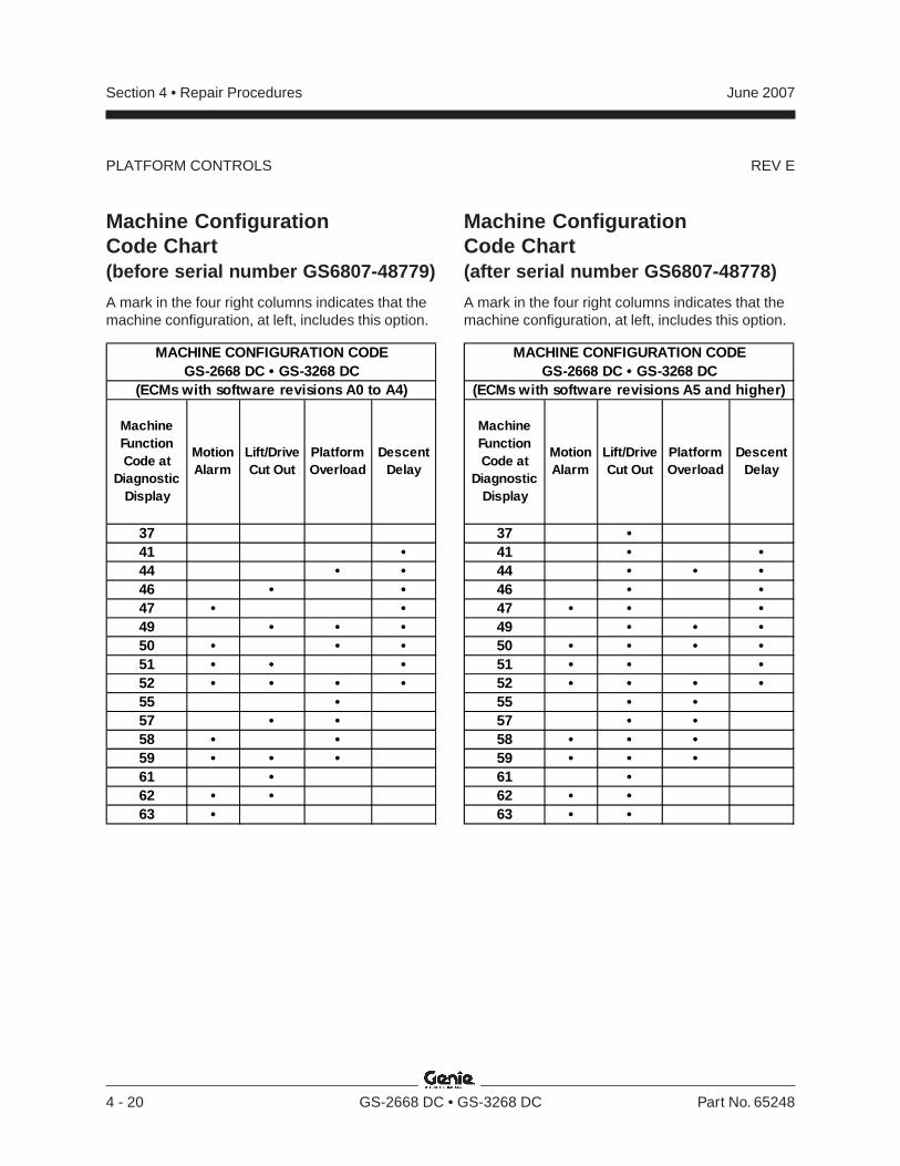
REV E
Section 4 • Repair Procedures June 2007
4 - 20 GS-2668 DC • GS-3268 DC Part No. 65248
PLATFORM CONTROLS
Machine ConfigurationCode Chart(before serial number GS6807-48779)
A mark in the four right columns indicates that themachine configuration, at left, includes this option.
Machine Function Code at
Diagnostic Display
Motion Alarm
Lift/Drive Cut Out
Platform Overload
Descent Delay
3741 •44 • •46 • •47 • •49 • • •50 • • •51 • • •52 • • • •55 •57 • •58 • •59 • • •61 •62 • •63 •
MACHINE CONFIGURATION CODEGS-2668 DC • GS-3268 DC
(ECMs with software revisions A0 to A4)
Machine ConfigurationCode Chart(after serial number GS6807-48778)
A mark in the four right columns indicates that themachine configuration, at left, includes this option.
Machine Function Code at
Diagnostic Display
Motion Alarm
Lift/Drive Cut Out
Platform Overload
Descent Delay
37 •41 • •44 • • •46 • •47 • • •49 • • •50 • • • •51 • • •52 • • • •55 • •57 • •58 • • •59 • • •61 •62 • •63 • •
MACHINE CONFIGURATION CODEGS-2668 DC • GS-3268 DC
(ECMs with software revisions A5 and higher)

REV E
Section 4 • Repair ProceduresJune 2007
Part No. 65248 GS-2668 DC • GS-3268 DC 4 - 21
PLATFORM CONTROLS
How to Activate the Battery DrainAlarm Option1 Pull out the red Emergency Stop button to the
on position at the ground controls.
2 Push in the red Emergency Stop button to theoff position at the platform controls.
3 Turn the key switch to platform control.
4 At the platform controls, press and hold the liftfunction select and speed select buttons, andpull out the red Emergency Stop button to theon position.
Result: The diagnostic display, at the platformcontrols and the ECM, will show "SC."
5 Release the lift function select and speed selectbuttons.
Result: The diagnostic display will show thecurrent configuration.
6 Press the speed select button.
Result: The 'ones' digit setting will be activatedand the current 'ones' setting will flash in thediagnostic display.
7 Press the horn button.
Result: A dot, located at the lower right of thediagnostic display window, will becomeilluminated. This indicates that the battery drainalarm option has been activated.
8 Press and hold the speed select button for aminimum of 3 seconds or until the 'ones' settingstops flashing.
9 Turn the key switch to the off position.
Note: Any change in software settings will not takeeffect until the key switch is turned to the offposition.
Note: To deactivate the battery drain alarm optionon a machine which has the option activated,repeat this procedure. When the ECM is in the 'SC'mode and the option is deactivated, there will notbe an illuminated dot in the diagnostic displaywindow.
How to Determine the BatteryVoltageThe diagnostic display on the platform controls isused to indicate the battery voltage at all timeswhen the machine is in normal operation.
Limp Mode: If the battery level falls to less than17.8V DC, the single bar in the diagnostic displaywill be flashing and machine drive speed is limitedto that of the raised drive speed. Refer to Section2, Specifications.
the battery level is 22.6V DC or higher
the battery level is 21.6 to 22.5V DC
the battery level is 20.7 to 21.5V DC
the battery level is 19.7 to 20.6V DC
the battery level is 17.8 to 19.6V DC
the battery level is less than 17.8V DC
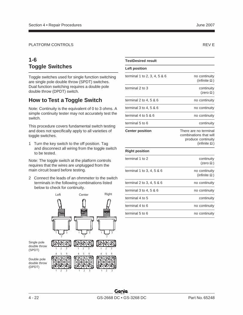
REV E
Section 4 • Repair Procedures June 2007
4 - 22 GS-2668 DC • GS-3268 DC Part No. 65248
Right
1-6Toggle Switches
Toggle switches used for single function switchingare single pole double throw (SPDT) switches.Dual function switching requires a double poledouble throw (DPDT) switch.
How to Test a Toggle SwitchNote: Continuity is the equivalent of 0 to 3 ohms. Asimple continuity tester may not accurately test theswitch.
This procedure covers fundamental switch testingand does not specifically apply to all varieties oftoggle switches.
1 Turn the key switch to the off position. Tagand disconnect all wiring from the toggle switchto be tested.
Note: The toggle switch at the platform controlsrequires that the wires are unplugged from themain circuit board before testing.
2 Connect the leads of an ohmmeter to the switchterminals in the following combinations listedbelow to check for continuity.
Single poledouble throw(SPDT)
Double poledouble throw(DPDT)
CenterLeft
TestDesired result
Left position
terminal 1 to 2, 3, 4, 5 & 6 no continuity(infinite )
terminal 2 to 3 continuity(zero )
terminal 2 to 4, 5 & 6 no continuity
terminal 3 to 4, 5 & 6 no continuity
terminal 4 to 5 & 6 no continuity
terminal 5 to 6 continuity
Center position There are no terminalcombinations that will
produce continuity(infinite )
Right position
terminal 1 to 2 continuity(zero )
terminal 1 to 3, 4, 5 & 6 no continuity(infinite )
terminal 2 to 3, 4, 5 & 6 no continuity
terminal 3 to 4, 5 & 6 no continuity
terminal 4 to 5 continuity
terminal 4 to 6 no continuity
terminal 5 to 6 no continuity
1
2
3
4 5 6
1 2 3
1
2
3 1
2
3
1 2 3 1 2 3
1 2 3 1 2 3 1 2 3
4 5 6 4 5 6
PLATFORM CONTROLS
REV B
Section 4 • Repair ProceduresJune 2007
Part No. 65248 GS-2668 DC • GS-3268 DC 4 - 23
2-1Platform
How to Remove the PlatformBodily injury hazard. Thisprocedure requires specific repairskills, lifting equipment and asuitable workshop. Attempting thisprocedure without these skills andtools could result in death orserious injury and significantcomponent damage. Dealerservice is required.
Note: Perform this procedure with the platform inthe stowed position and the platform extensiondeck fully retracted and locked in position.
1 Start the engine from the ground controls andraise the platform 9 to 10 feet / 2.7 to 3 m.
2 Lift the safety arm, move it to the center of thescissor arm and rotate down to a verticalposition.
3 Lower the platform onto the safety arm. Turnthe machine off.
Crushing hazard. Keep handsclear of the safety arm whenlowering the platform.
4 Remove the hose clamps or zip ties that securethe power to platform wiring to the bottom of theplatform.
Component damage hazard. Besure not to cut the power toplatform wiring.
5 GS-2668 DC before serial number 26563 andGS-3268 DC before serial number 41200:Remove the platform extension limit switchmounting fasteners and remove the limit switch.Do not disconnect the wiring.
6 Raise the platform and return the safety arm tothe stowed position.
7 Lower the platform to the stowed position andturn the machine off.
8 Remove the mounting fasteners that secure theplatform controls quick disconnect plug to theplatform.
9 Twist the connector to disconnect the platformcontrols from the plug.
10 Remove the platform control box from theplatform and lay it off to the side.
Component damage hazard. Theplatform controls wiring can bedamaged if it is kinked or pinched.
11 Remove the cover to the AC power to platformoutlet. Tag and disconnect the wiring from theoutlet.
Electrocution hazard. Contact withelectrically charged circuits couldresult in death or serious injury.Remove all rings, watches andother jewelry.
12 Pull the wiring down through the platform tube.
Component damage hazard. TheAC power to platform wiring canbe damaged if it is kinked orpinched.
Note: If your machine is equipped with an air line toplatform option, the air line must be disconnectedfrom the platform before removal.
Platform Components
REV B
Section 4 • Repair Procedures June 2007
4 - 24 GS-2668 DC • GS-3268 DC Part No. 65248
13 Support the platform with a forklift at thesteer end of the machine. Do not apply anylifting pressure.
14 Attach a strap from the platform railings to thecarriage on the forklift to support the platform.
15 Remove the retaining fasteners from theplatform pivot pins at the steer end of themachine.
16 Use a slide hammer to remove the pins.
Crushing hazard. The platform willfall when the pivot pins areremoved if not properly supportedby the forklift.
17 Remove the retaining fasteners from theplatform pivot pins at the non-steer end of themachine.
18 Use a slide hammer to remove the pins.
Crushing hazard. The platform willfall when the pivot pins areremoved if not properly supportedby the forklift.
19 Carefully lift the platform off of the machine andplace it on a structure capable of supporting it.
Crushing hazard. The platform willbecome unbalanced and fall whenremoved from the machine if notproperly supported and secured tothe forklift.
Note: Note the position of the wear pads before theplatform is removed so that when the platform isinstalled they will be in the correct position.
2-2Platform Extension
How to Remove the PlatformExtension DeckNote: Perform this procedure with the platform inthe stowed position and the platform extensiondeck fully retracted and locked in position.
1 Remove the fasteners from the access cover onthe side of the platform at the non-steer end ofthe machine.
2 Remove the fasteners from the roller wheelmount.
3 Remove the wheel roller bolt and remove theroller wheel from the platform.
4 Repeat steps 1 through 3 for the other side ofthe platform.
5 Lift the platform extension lock handle.
6 Remove the two bolts that attach the platformextension lock handle assembly to the platformextension railing.
7 Remove the two bolts that attach the extensionlock pin bracket to the railing. Lay the lockhandle assembly off to the side.
8 GS-2668 DC before serial number 26563 andGS-3268 DC before serial number 41200:Remove the platform extension limit switchmounting fasteners and remove the limit switch.Do not disconnect the wiring.
PLATFORM COMPONENTS
REV B
Section 4 • Repair ProceduresJune 2007
Part No. 65248 GS-2668 DC • GS-3268 DC 4 - 25
9 Remove the platform controls from the platformand lay them off to the side.
10 Position a forklift at the steer end of themachine with the forks even with the bottom ofthe platform extension.
11 Carefully slide the platform extension out untilthe platform extension makes contact with thecarriage on the forklift.
12 Attach a lifting strap from the platform extensionrailings to the carriage on the forklift to supportthe platform extension.
13 Carefully slide the platform extension out andaway from the platform and place it on astructure capable of supporting it.
Crushing hazard. The platformextension will become unbalancedand fall when removed from themachine if not properly supportedand secured to the forklift.
PLATFORM COMPONENTS
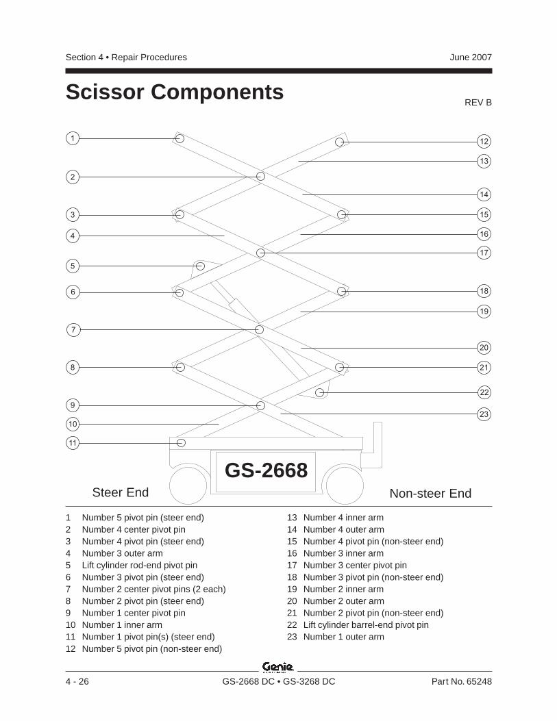
REV B
Section 4 • Repair Procedures June 2007
4 - 26 GS-2668 DC • GS-3268 DC Part No. 65248
Scissor Components
GS-2668
21
22
17
14
20
16
23
12
13
15
9
4
5
6
7
2
10
1
3
8
11
18
19
1 Number 5 pivot pin (steer end)2 Number 4 center pivot pin3 Number 4 pivot pin (steer end)4 Number 3 outer arm5 Lift cylinder rod-end pivot pin6 Number 3 pivot pin (steer end)7 Number 2 center pivot pins (2 each)8 Number 2 pivot pin (steer end)9 Number 1 center pivot pin10 Number 1 inner arm11 Number 1 pivot pin(s) (steer end)12 Number 5 pivot pin (non-steer end)
13 Number 4 inner arm14 Number 4 outer arm15 Number 4 pivot pin (non-steer end)16 Number 3 inner arm17 Number 3 center pivot pin18 Number 3 pivot pin (non-steer end)19 Number 2 inner arm20 Number 2 outer arm21 Number 2 pivot pin (non-steer end)22 Lift cylinder barrel-end pivot pin23 Number 1 outer arm
Non-steer EndSteer End
REV B
Section 4 • Repair ProceduresJune 2007
Part No. 65248 GS-2668 DC • GS-3268 DC 4 - 27
SCISSOR COMPONENTS
3-1Scissor Assembly, GS-2668 DC
How to Disassemble theScissor Assembly, GS-2668 DC
Bodily injury hazard. Thisprocedure requires specific repairskills, lifting equipment and asuitable workshop. Attempting thisprocedure without these skills andtools could result in death orserious injury and significantcomponent damage. Dealerservice is required.
Note: When removing a hose assembly or fitting,the O-ring (if equipped) on the fitting and/or hoseend must be replaced. All connections must betorqued to specification during installation. Refer toSection 2, Hydraulic Hose and Fitting TorqueSpecifications.
1 Remove the platform. See 2-1, How to Removethe Platform.
2 Remove the cables from the number 4 outerarm (index #14).
3 Remove the cables from the upper cable traysupport.
4 Remove the cables from the number 3 innerarm (index #16) and lay the cables off to theside.
Component damage hazard.Cables can be damaged if theyare kinked or pinched.
5 Remove the mounting fasteners from the uppercable tray supports.
6 Remove the upper cable tray from the scissorassembly.
Component damage hazard.Cables can be damaged if theyare kinked or pinched.
7 Connect the platform controls to the quickdisconnect plug to allow the machine tooperate.
8 Turn the key switch to ground control and pullout the red Emergency Stop button to the onposition at both the ground and platformcontrols. Start the engine.
9 Raise the platform 9 to 10 feet / 2.7 to 3 m.
10 Remove the safety arm from the number 3 innerarm (index #16).
11 Install the safety arm on the number 2 inner arm(index #19) at the steer end of the machine.
12 Lift the safety arm, move to the center of thescissor arm and rotate down to a verticalposition.
13 Lower the scissor assembly onto the safetyarm.
Crushing hazard. Keep handsclear of the safety arm whenlowering the platform.
14 Turn the key switch to the off position and pushin the red Emergency Stop button to the offposition at both the ground and platformcontrols.
15 Attach a lifting strap from an overhead crane tothe number 4 outer arm (index #14).
16 Support the number 4 inner arm (index #13)with a second overhead crane at the non-steerend.
REV B
Section 4 • Repair Procedures June 2007
4 - 28 GS-2668 DC • GS-3268 DC Part No. 65248
SCISSOR COMPONENTS
17 Remove the external snap rings from thenumber 4 center pivot pin (index #2).
18 Use a soft metal drift to remove the number 4center pivot pin (index #2).
Crushing hazard. The number 4outer arm (index #14) couldbecome unbalanced and fall if notproperly supported when the pivotpin is removed.
19 Remove the external snap rings from thenumber 4 pivot pin (index #15) at the non-steerend of the machine.
20 Use a soft metal drift to remove the number 4pivot pin (index #15) from the non-steer end.Remove the number 4 outer arm (index #14)from the machine.
Crushing hazard. The number 4outer arm (index #14) couldbecome unbalanced and fall if notproperly supported when removedfrom the machine.
21 Remove the external snap rings from thenumber 4 pivot pin (index #3).
22 Use a soft metal drift to remove the number 4pivot pin (index #3). Remove the number 4inner arm (index #13) from the machine.
Crushing hazard. The number 4inner arm (index #13) couldbecome unbalanced and fall if notproperly supported when removedfrom the machine.
23 Attach a lifting strap from an overhead crane tothe number 3 outer arm (index #4) at theground controls side.
24 Remove the external snap rings from thenumber 3 center pivot pin (index #17) at theground controls side.
25 Use a soft metal drift to tap the number 3 centerpivot pin (index #17) halfway out at the groundcontrols side.
26 Remove the external snap rings from thenumber 3 pivot pin (index #18) at the non-steerend.
27 Use a soft metal drift to tap the number 3 pivotpin (index #18) halfway out at the non-steer endof the machine. Remove the number 3 outerarm (index #4) at the ground controls side fromthe machine.
Crushing hazard. The number 3outer arm (index #4) at the groundcontrols side could becomeunbalanced and fall if not properlysupported when removed from themachine.
28 Attach a lifting strap from an overhead crane tothe number 3 outer arm (index #4) at thebattery pack side of the machine.
29 Remove the external snap rings from thenumber 3 center pivot pin (index #17) at thebattery pack side of the machine.
30 Use a soft metal drift to tap the number 3 centerpivot pin (index #17) at the battery pack side ofthe machine in the other direction.
31 Use a soft metal drift to tap the number 3 pivotpin (index #18) at the non-steer end in the otherdirection. Remove the number 3 outer arm(index #4) from the battery pack side of themachine.
Crushing hazard. The number 3outer arm (index #4) at the batterypack side could becomeunbalanced and fall if not properlysupported when removed from themachine.
REV B
Section 4 • Repair ProceduresJune 2007
Part No. 65248 GS-2668 DC • GS-3268 DC 4 - 29
SCISSOR COMPONENTS
32 Remove the cables from the lower cable tray.Lay the cables off to the side of the machine.
33 Remove the mounting fasteners from the lowercable tray mounting bracket on the number 2center pivot pin (index #7) at the battery packside of the machine.
34 Remove the mounting fasteners from the lowercable tray supports at both ends of the lowercable tray.
35 Remove the lower cable tray from the machine.
Component damage hazard.Cables can be damaged if theyare kinked or pinched.
36 Attach a lifting strap from an overhead crane tothe lug on the rod end of the lift cylinder.
37 Support the number 3 inner arm (index #16)with a second overhead crane at the non-steerend of the machine.
38 Remove the pin retaining fasteners from thecylinder rod-end pivot pin (index #5). Use a softmetal drift to remove the pin.
Crushing hazard. The cylindercould fall if not properly supportedwhen the pin is removed.
39 Tag, disconnect and plug the hydraulic hose onthe lift cylinder. Cap the fitting on the cylinder.
Bodily injury hazard. Sprayinghydraulic oil can penetrate andburn skin. Loosen hydraulicconnections very slowly to allowthe oil pressure to dissipategradually. Do not allow oil to squirtor spray.
40 Tag and disconnect the wiring from the solenoidvalve on the lift cylinder.
41 Remove the pin retaining fasteners from thecylinder barrel-end pivot pin (index #22). Use asoft metal drift to remove the pin. Remove thecylinder from the scissor assembly.
Crushing hazard. The cylindercould become unbalanced and fallif not properly supported whenremoved from the assembly.
42 Remove the external snap rings from thenumber 3 pivot pin (index #6) at the steer end.
43 Use a soft metal drift to remove the number 3pivot pin (index #6) at the steer end. Removethe number 3 inner arm (index #16) from themachine.
Crushing hazard. The number 3inner arm (index #16) couldbecome unbalanced and fall if notproperly supported when removedfrom the machine.
44 Attach a lifting strap from an overhead crane tothe number 2 outer arm (index #20) at theground controls side.
45 Support the number 2 inner arm (index #19) atthe non-steer end with a second overheadcrane.
46 Remove the external snap rings from thenumber 2 center pivot pin (index #7) at theground controls side.
REV B
Section 4 • Repair Procedures June 2007
4 - 30 GS-2668 DC • GS-3268 DC Part No. 65248
SCISSOR COMPONENTS
47 Use a soft metal drift to remove the number 2center pivot pin (index #7) at the groundcontrols side.
Crushing hazard. The number 2outer arm (index #20) couldbecome unbalanced and fall if notproperly supported when the pivotpin is removed.
48 Remove the external snap rings from thenumber 2 pivot pin (index #21) at the non-steerend.
49 Use a soft metal drift to tap the number 2 pivotpin (index #21) halfway out at the non-steer endof the machine. Remove the number 2 outerarm (index #20) at the ground controls sidefrom the machine.
Crushing hazard. The number 2outer arm (index #20) at theground controls side couldbecome unbalanced and fall if notproperly supported when removedfrom the machine.
50 Attach a lifting strap from an overhead crane tothe number 2 outer arm (index #20) at thebattery pack side.
51 Remove the external snap rings from thenumber 2 center pivot pin (index #7) at thebattery pack side.
52 Use a soft metal drift to remove the number 2center pivot pin (index #7) at the battery packside.
Crushing hazard. The number 2outer arm (index #20) couldbecome unbalanced and fall if notproperly supported when the pivotpin is removed.
53 Use a soft metal drift to tap the number 2 pivotpin (index #21) at the non steer end in the otherdirection. Remove the number 2 outer arm(index #20) from the battery pack side of themachine.
Crushing hazard. The number 2outer arm (index #20) at thebattery pack side could becomeunbalanced and fall if not properlysupported when removed from themachine.
54 Support the number 1 outer arm (index #23)with a second overhead crane at the steer end.
55 Remove the external snap rings from thenumber 2 pivot pin (index #8) at the steer end.
56 Use a soft metal drift to remove the number 2pivot pin (index #8) at the steer end. Removethe number 2 inner arm (index #19) from themachine.
Crushing hazard. The number 2inner arm (index #19) couldbecome unbalanced and fall if notproperly supported when removedfrom the machine.
57 Remove the cables from the number 1 innerarm (index #10). Lay the cables off to the sideof the machine.
Component damage hazard.Cables can be damaged if theyare kinked or pinched.
58 Support and secure the entry ladder to anappropriate lifting device. Remove the entryladder mounting fasteners. Remove the entryladder from the machine.
Crushing hazard. The entry laddercould become unbalanced and fallif not properly supported andsecured to the lifting device.
REV B
Section 4 • Repair ProceduresJune 2007
Part No. 65248 GS-2668 DC • GS-3268 DC 4 - 31
SCISSOR COMPONENTS
59 Secure both ends of the scissor arms togetherwith a strap or other suitable device.
60 Attach each end of a lifting strap to each end ofthe scissor assembly.
61 Attach an overhead crane to the center of thestrap.
62 Remove the pin retaining fasteners from thenumber 1 pivot pin(s) (index #11). Use a softmetal drift to remove the pin(s).
63 Lift the scissor assembly slightly and slide thescissor assembly towards the non-steer end ofthe machine to allow the wear pads to slide outof the channel.
Crushing hazard. The scissorassembly could fall if not properlysupported by the overhead crane.
64 Remove the scissor assembly from themachine and place it on a structure capableof supporting it.
Crushing hazard. The scissorassembly could becomeunbalanced and fall if not properlysupported and secured to theoverhead crane.
Note: During removal, the lifting strap connected tothe overhead crane will need to be carefullyadjusted for proper balancing.
65 Remove the straps securing the scissor armstogether.
66 Attach a lifting strap from an overhead crane tothe number 1 outer arm (index #23).
67 Support the number 1 inner arm (index #10)with a second overhead crane.
68 Remove the external snap rings from thenumber 1 center pivot pin (index #9).
69 Use a soft metal drift to remove the number 1center pivot pin (index #9).
Crushing hazard. The scissorassembly could becomeunbalanced and fall if not properlysupported when the center pivotpin is removed.
70 Remove the number 1 outer arm (index #23)from the assembly.
Crushing hazard. The number 1inner arm (index #10) couldbecome unbalanced and fall if notproperly supported when removedfrom the machine.

REV B
Section 4 • Repair Procedures June 2007
4 - 32 GS-2668 DC • GS-3268 DC Part No. 65248
How to Replace the Scissor ArmWear Pads1 Remove the platform. See 2-1, How to Remove
the Platform.
2 Remove the mounting fasteners from thestationary wear pads on the platform.
Note: Note the position of the wear pads beforethey are removed so when the new ones areinstalled they will be in the correct position.
3 Connect the platform controls to the quickdisconnect plug to allow the machine tooperate.
4 Turn the key switch to ground control and pullout the red Emergency Stop button to the onposition at both the ground and platformcontrols. Start the engine.
5 Raise the scissor assembly9 to 10 feet / 2.7 to 3 m.
6 Lift the safety arm, move it to the center of thescissor arm and rotate down to a verticalposition.
7 Lower the platform onto the safety arm.
Crushing hazard. Keep handsclear of moving parts whenlowering the scissor arms onto thesafety arm.
8 Turn the key switch to the off position and pushin the red Emergency Stop buttons to the offposition at both the ground and platformcontrols.
9 Secure both ends of the scissor arms togetherwith a strap or other suitable device.
10 Attach a strap from an overhead crane to thenon-steer end of the scissor arms.
11 Raise the scissor arms slightly at the non-steerend with the overhead crane just enough totake the pressure off of the non-steer end slideblocks.
12 Remove the pin retaining fasteners from theslide block pivot pin.
13 Place a rod through the pin and twist to removethe pin.
14 Remove the slide block and remove the wearpad mounting fasteners.
15 Install the new wear pad.
16 Repeat steps 12 through 15 for the other wearpad slide block.
17 Install the wear pad slide blocks into the drivechassis and install the slide block pivot pins andpin retaining fasteners.
SCISSOR COMPONENTS
REV B
Section 4 • Repair ProceduresJune 2007
Part No. 65248 GS-2668 DC • GS-3268 DC 4 - 33
This page intentionally left blank.
SCISSOR COMPONENTS
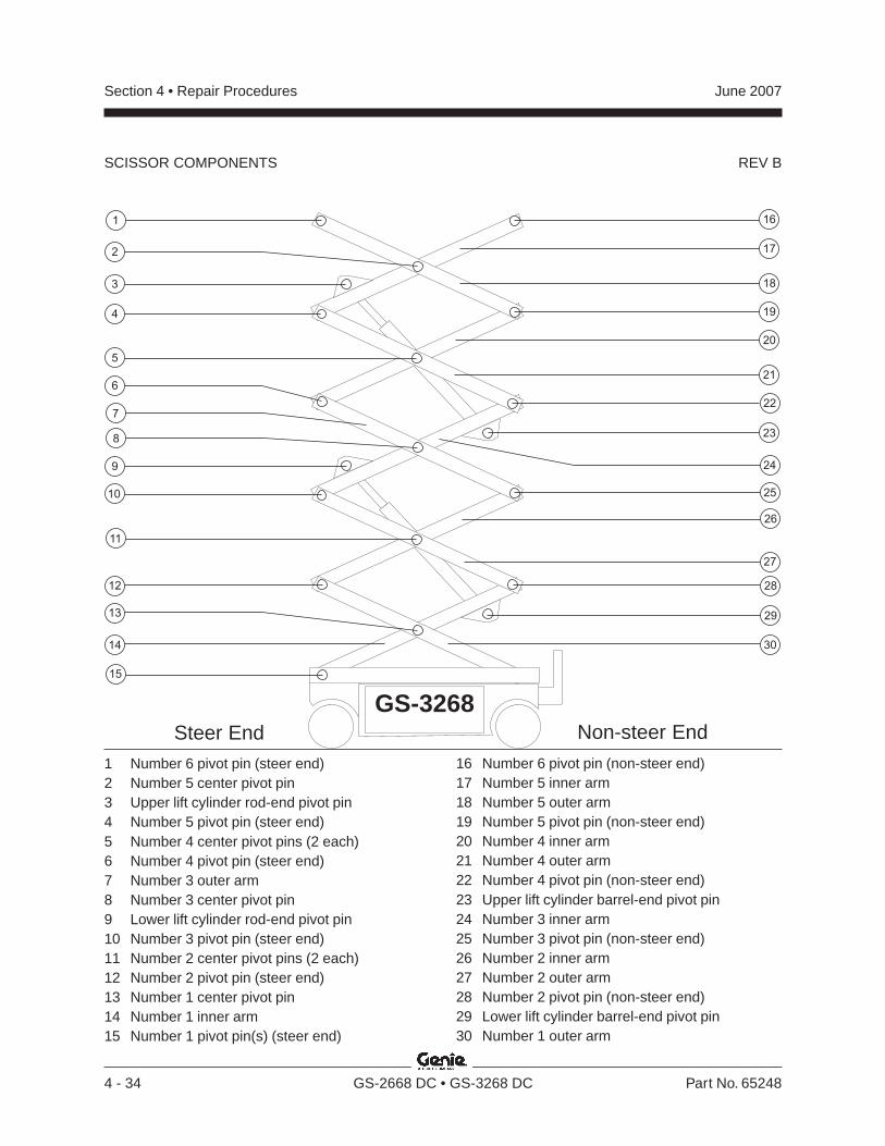
REV B
Section 4 • Repair Procedures June 2007
4 - 34 GS-2668 DC • GS-3268 DC Part No. 65248
SCISSOR COMPONENTS
22
30
28
29
2510
3
4
5
11
19
17
26
20
27
18
21
8
16
15
23
2
1
9
GS-3268
13
24
6
7
12
14
1 Number 6 pivot pin (steer end)2 Number 5 center pivot pin3 Upper lift cylinder rod-end pivot pin4 Number 5 pivot pin (steer end)5 Number 4 center pivot pins (2 each)6 Number 4 pivot pin (steer end)7 Number 3 outer arm8 Number 3 center pivot pin9 Lower lift cylinder rod-end pivot pin10 Number 3 pivot pin (steer end)11 Number 2 center pivot pins (2 each)12 Number 2 pivot pin (steer end)13 Number 1 center pivot pin14 Number 1 inner arm15 Number 1 pivot pin(s) (steer end)
16 Number 6 pivot pin (non-steer end)17 Number 5 inner arm18 Number 5 outer arm19 Number 5 pivot pin (non-steer end)20 Number 4 inner arm21 Number 4 outer arm22 Number 4 pivot pin (non-steer end)23 Upper lift cylinder barrel-end pivot pin24 Number 3 inner arm25 Number 3 pivot pin (non-steer end)26 Number 2 inner arm27 Number 2 outer arm28 Number 2 pivot pin (non-steer end)29 Lower lift cylinder barrel-end pivot pin30 Number 1 outer arm
Non-steer EndSteer End
REV B
Section 4 • Repair ProceduresJune 2007
Part No. 65248 GS-2668 DC • GS-3268 DC 4 - 35
SCISSOR COMPONENTS
3-2Scissor Assembly, GS-3268 DC
How to Disassemble theScissor Assembly, GS-3268 DC
Bodily injury hazard. Thisprocedure requires specific repairskills, lifting equipment and asuitable workshop. Attempting thisprocedure without these skills andtools could result in death orserious injury and significantcomponent damage. Dealerservice is required.
Note: When removing a hose assembly or fitting,the O-ring (if equipped) on the fitting and/or hoseend must be replaced. All connections must betorqued to specification during installation. Refer toSection 2, Hydraulic Hose and Fitting TorqueSpecifications.
1 Remove the platform. See 2-1, How to Removethe Platform.
2 Remove the cables from the side of the number5 outer arm (index #18) at the battery packside.
Component damage hazard.Cables can be damaged if theyare kinked or pinched.
3 Attach a lifting strap from an overhead crane tothe number 5 outer arm (index #18).
4 Remove the external snap rings from thenumber 5 center pivot pin (index #2).
5 Use a soft metal drift to remove the number 5center pivot pin (index #2).
6 Remove the external snap rings from thenumber 5 pivot pin (index #19) at the non-steerend of the machine.
7 Use a soft metal drift to remove the number 5pivot pin (index #19) from the non-steer end ofthe machine. Remove the number 5 outer arm(index #18) from the machine.
Crushing hazard. The number 5outer arm (index #18) couldbecome unbalanced and fall if notproperly supported when removedfrom the machine.
8 Remove the cable clamps from the number 5inner arm (index #17) and the upper cable tray.Lay the cables off to the side of the machine.
Component damage hazard.Cables can be damaged if theyare kinked or pinched.
9 Tag, disconnect and plug the hydraulic hose onthe upper lift cylinder. Cap the fitting on thecylinder.
Bodily injury hazard. Sprayinghydraulic oil can penetrate andburn skin. Loosen hydraulicconnections very slowly to allowthe oil pressure to dissipategradually. Do not allow oil to squirtor spray.
10 Attach a lifting strap from an overhead crane tothe lug on the rod end of the upper lift cylinder.
11 Remove the pin retaining fasteners from theupper cylinder rod-end pivot pin (index #3). Usea soft metal drift to remove the pin.
Crushing hazard. The cylindercould fall if not properly supportedwhen the pin is removed.
12 Lower the cylinder onto the number 3 centerpivot pin (index #8).
13 Attach a lifting strap from an overhead crane tothe number 5 inner arm (index #17).
14 Remove the external snap rings from thenumber 5 pivot pin (index #4).
REV B
Section 4 • Repair Procedures June 2007
4 - 36 GS-2668 DC • GS-3268 DC Part No. 65248
SCISSOR COMPONENTS
15 Use a soft metal drift to remove the number 5pivot pin (index #4). Remove the number 5inner arm (index #17) from the machine.
Crushing hazard. The number 5inner arm (index #17) couldbecome unbalanced and fall if notproperly supported when removedfrom the machine.
16 Remove the mounting fasteners from the uppercable tray mounting bracket on the number 4center pivot pin (index #5) at the battery packside of the machine.
17 Remove the mounting fasteners from the uppercable tray supports at both ends of the uppercable tray.
18 Remove the upper cable tray.
19 Tag and disconnect the wiring from the solenoidvalve on the lift cylinder.
20 Remove the safety arm from the number 4 innerarm (index #20).
21 Install the safety arm on the number 2 inner arm(index #26) at the steer end of the machine.
22 Attach a lifting strap from an overhead crane tothe number 4 outer arm (index #21) at theground controls side.
23 Support the number 4 inner arm (index #20)with a second overhead crane at the non-steerend of the machine.
24 Remove the external snap rings from thenumber 4 center pivot pin (index #5) at theground controls side.
25 Use a soft metal drift to remove the number 4center pivot pin (index #5) at the groundcontrols side.
26 Remove the external snap rings from thenumber 4 pivot pin (index #22) at the non-steerend of the machine.
27 Use a soft metal drift to tap the number 4 pivotpin (index #22) halfway out at the non-steer endof the machine. Remove the number 4 outerarm (index #21) at the ground controls sidefrom the machine.
Crushing hazard. The number 4outer arm (index #21) at theground controls side couldbecome unbalanced and fall if notproperly supported when removedfrom the machine.
28 Attach a lifting strap from an overhead crane tothe number 4 outer arm (index #21) at thebattery pack side of the machine.
29 Remove the external snap rings from thenumber 4 center pivot pin (index #5) at thebattery pack side of the machine.
30 Use a soft metal drift to remove the number 4center pivot pin (index #5) at the battery packside of the machine.
31 Use a soft metal drift to tap the number 4 pivotpin (index #22) in the other direction. Removethe number 4 outer arm (index #21) from thebattery pack side of the machine.
Crushing hazard. The number 4outer arm at the battery pack side(index #21) could becomeunbalanced and fall if not properlysupported when removed from themachine.
32 Remove the external snap rings from thenumber 4 pivot pin (index #6) at the steer endof the machine.
33 Use a soft metal drift to remove the number 4pivot pin (index #6) at the steer end. Removethe number 4 inner arm (index #20) from themachine.
Crushing hazard. The number 4inner arm (index #20) couldbecome unbalanced and fall if notproperly supported when removedfrom the machine.
REV B
Section 4 • Repair ProceduresJune 2007
Part No. 65248 GS-2668 DC • GS-3268 DC 4 - 37
SCISSOR COMPONENTS
34 Connect the platform controls to the quickdisconnect plug to allow the machine tooperate.
35 Turn the key switch to ground control and pullout the red Emergency Stop button to the onposition at both the ground and platformcontrols.
36 Raise the scissor assembly9 to 10 feet / 2.7 to 3 m.
37 Lift the safety arm, move it to the center of thescissor arm and rotate down to a verticalposition. Lower the scissor assembly onto thesafety arm.
Crushing hazard. Keep handsclear of the safety arm whenlowering the platform.
38 Turn the key switch to the off position and pushin the red Emergency Stop button to the offposition at both the ground and platformcontrols.
39 Attach a lifting strap from an overhead crane tothe lug on the rod end of the upper lift cylinder.Raise the rod end of the cylinder to a verticalposition.
40 Remove the pin retaining fasteners from theupper cylinder barrel-end pivot pin (index #23).Use a soft metal drift to remove the pin.Remove the cylinder from the machine.
Crushing hazard. The cylindercould become unbalanced and fallwhen removed from the machine ifnot properly supported.
Component damage hazard. Becareful not to damage the valve orfittings on the cylinder whileremoving it from the machine.
41 Attach a lifting strap from an overhead crane tothe number 3 outer arm (index #7) at theground controls side of the machine.
42 Attach a lifting strap from an overhead crane tothe lug on the rod end of the lift cylinder.
43 Support the number 3 inner arm (index #16)with a second overhead crane at the non-steerend of the machine.
44 Remove the pin retaining fasteners from thecylinder rod-end pivot pin (index #5). Use a softmetal drift to remove the pin.
Crushing hazard. The cylindercould fall if not properly supportedwhen the pin is removed.
45 Tag, disconnect and plug the hydraulic hose onthe lift cylinder. Cap the fitting on the cylinder.
Bodily injury hazard. Sprayinghydraulic oil can penetrate andburn skin. Loosen hydraulicconnections very slowly to allowthe oil pressure to dissipategradually. Do not allow oil to squirtor spray.
46 Tag and disconnect the wiring from the solenoidvalve on the lift cylinder.
47 Remove the pin retaining fasteners from thecylinder barrel-end pivot pin (index #22). Use asoft metal drift to remove the pin. Remove thecylinder from the scissor assembly.
Crushing hazard. The cylindercould become unbalanced and fallif not properly supported whenremoved from the assembly.
48 Remove the external snap rings from thenumber 3 pivot pin (index #6) at the steer end.
REV B
Section 4 • Repair Procedures June 2007
4 - 38 GS-2668 DC • GS-3268 DC Part No. 65248
SCISSOR COMPONENTS
49 Use a soft metal drift to remove the number 3pivot pin (index #6) at the steer end. Removethe number 3 inner arm (index #16) from themachine.
Crushing hazard. The number 3inner arm (index #16) couldbecome unbalanced and fall if notproperly supported when removedfrom the machine.
50 Attach a lifting strap from an overhead crane tothe number 2 outer arm (index #20) at theground controls side.
51 Support the number 2 inner arm (index #19) atthe non-steer end with a second overheadcrane.
52 Remove the external snap rings from thenumber 2 center pivot pin (index #7) at theground controls side.
53 Use a soft metal drift to remove the number 2center pivot pin (index #7) at the groundcontrols side.
Crushing hazard. The number 2outer arm (index #20) couldbecome unbalanced and fall if notproperly supported when the pivotpin is removed.
54 Remove the external snap rings from thenumber 2 pivot pin (index #21) at the non-steerend.
55 Use a soft metal drift to tap the number 2 pivotpin (index #21) halfway out at the non-steer endof the machine. Remove the number 2 outerarm (index #20) at the ground controls sidefrom the machine.
Crushing hazard. The number 2outer arm (index #20) at theground controls side couldbecome unbalanced and fall if notproperly supported when removedfrom the machine.
56 Attach a lifting strap from an overhead crane tothe number 2 outer arm (index #20) at thebattery pack side.
57 Remove the external snap rings from thenumber 2 center pivot pin (index #7) at thebattery pack side.
58 Use a soft metal drift to remove the number 2center pivot pin (index #7) at the battery packside.
Crushing hazard. The number 2outer arm (index #20) couldbecome unbalanced and fall if notproperly supported when the pivotpin is removed.
59 Use a soft metal drift to tap the number 2 pivotpin (index #21) at the non steer end in the otherdirection. Remove the number 2 outer arm(index #20) from the battery pack side of themachine.
Crushing hazard. The number 2outer arm (index #20) at thebattery pack side could becomeunbalanced and fall if not properlysupported when removed from themachine.
60 Support the number 1 outer arm (index #23)with a second overhead crane at the steer end.
61 Remove the external snap rings from thenumber 2 pivot pin (index #8) at the steer end.
62 Use a soft metal drift to remove the number 2pivot pin (index #8) at the steer end. Removethe number 2 inner arm (index #19) from themachine.
Crushing hazard. The number 2inner arm (index #19) couldbecome unbalanced and fall if notproperly supported when removedfrom the machine.
REV B
Section 4 • Repair ProceduresJune 2007
Part No. 65248 GS-2668 DC • GS-3268 DC 4 - 39
SCISSOR COMPONENTS
63 Remove the cables from the number 1 innerarm (index #10). Lay the cables off to the sideof the machine.
Component damage hazard.Cables can be damaged if theyare kinked or pinched.
64 Support and secure the entry ladder to anappropriate lifting device. Remove the entryladder mounting fasteners. Remove the entryladder from the machine.
Crushing hazard. The entry laddercould become unbalanced and fallif not properly supported andsecured to the lifting device.
65 Secure both ends of the scissor arms togetherwith a strap or other suitable device.
66 Attach each end of a lifting strap to each end ofthe scissor assembly.
67 Attach an overhead crane to the center of thestrap.
68 Remove the pin retaining fasteners from thenumber 1 pivot pin(s) (index #11). Use a softmetal drift to remove the pin(s).
69 Lift the scissor assembly slightly and slide thescissor assembly towards the non-steer end ofthe machine to allow the wear pads to slide outof the channel.
Crushing hazard. The scissorassembly could fall if not properlysupported by the overhead crane.
70 Remove the scissor assembly from themachine and place it on a structure capable ofsupporting it.
Crushing hazard. The scissorassembly could becomeunbalanced and fall if not properlysupported and secured to theoverhead crane.
Note: During removal, the lifting strap connected tothe overhead crane will need to be carefullyadjusted for proper balancing.
71 Remove the straps securing the scissor armstogether.
72 Attach a lifting strap from an overhead crane tothe number 1 outer arm (index #23).
73 Support the number 1 inner arm (index #10)with a second overhead crane.
74 Remove the external snap rings from thenumber 1 center pivot pin (index #9).
75 Use a soft metal drift to remove the number 1center pivot pin (index #9).
Crushing hazard. The scissorassembly could becomeunbalanced and fall if not properlysupported when the center pivotpin is removed.
76 Remove the number 1 outer arm (index #23)from the assembly.
Crushing hazard. The number 1inner arm (index #10) couldbecome unbalanced and fall if notproperly supported when removedfrom the machine.
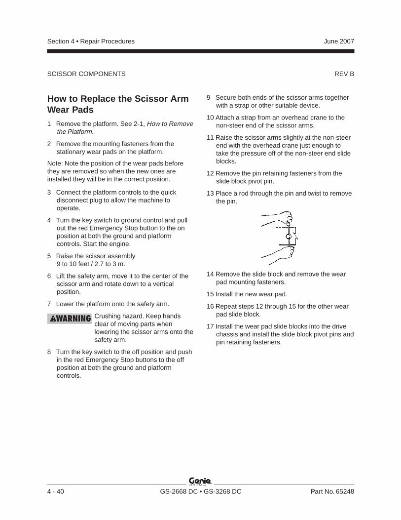
REV B
Section 4 • Repair Procedures June 2007
4 - 40 GS-2668 DC • GS-3268 DC Part No. 65248
SCISSOR COMPONENTS
How to Replace the Scissor ArmWear Pads1 Remove the platform. See 2-1, How to Remove
the Platform.
2 Remove the mounting fasteners from thestationary wear pads on the platform.
Note: Note the position of the wear pads beforethey are removed so when the new ones areinstalled they will be in the correct position.
3 Connect the platform controls to the quickdisconnect plug to allow the machine tooperate.
4 Turn the key switch to ground control and pullout the red Emergency Stop button to the onposition at both the ground and platformcontrols. Start the engine.
5 Raise the scissor assembly9 to 10 feet / 2.7 to 3 m.
6 Lift the safety arm, move it to the center of thescissor arm and rotate down to a verticalposition.
7 Lower the platform onto the safety arm.
Crushing hazard. Keep handsclear of moving parts whenlowering the scissor arms onto thesafety arm.
8 Turn the key switch to the off position and pushin the red Emergency Stop buttons to the offposition at both the ground and platformcontrols.
9 Secure both ends of the scissor arms togetherwith a strap or other suitable device.
10 Attach a strap from an overhead crane to thenon-steer end of the scissor arms.
11 Raise the scissor arms slightly at the non-steerend with the overhead crane just enough totake the pressure off of the non-steer end slideblocks.
12 Remove the pin retaining fasteners from theslide block pivot pin.
13 Place a rod through the pin and twist to removethe pin.
14 Remove the slide block and remove the wearpad mounting fasteners.
15 Install the new wear pad.
16 Repeat steps 12 through 15 for the other wearpad slide block.
17 Install the wear pad slide blocks into the drivechassis and install the slide block pivot pins andpin retaining fasteners.
REV B
Section 4 • Repair ProceduresJune 2007
Part No. 65248 GS-2668 DC • GS-3268 DC 4 - 41
3-3Lift Cylinder
How to Remove a Lift Cylinder,GS-2668 DC
Bodily injury hazard. Thisprocedure requires specific repairskills, lifting equipment and asuitable workshop. Attempting thisprocedure without these skills andtools could result in death orserious injury and significantcomponent damage. Dealerservice is strongly recommended.
Note: When removing a hose assembly or fitting,the O-ring (if equipped) on the fitting and/or hoseend must be replaced. All connections must betorqued to specification during installation. Refer toSection 2, Hydraulic Hose and Fitting TorqueSpecifications.
1 Raise the platform 9 to 10 feet / 2.7 to 3 m.
2 Lift the safety arm, move to the center of thescissor arm and rotate down to a verticalposition.
3 Lower the platform onto the safety arm.
Crushing hazard. Keep handsclear of the safety arm whenlowering the platform.
4 Tag and disconnect the wiring from the solenoidvalve at the barrel end of the lift cylinder.
5 Before serial number 41200: Tag anddisconnect the manual lowering cable from thesolenoid.
Note: During assembly, the manual platformlowering cable needs to be properly adjusted. See4-1, How to Adjust the Manual Platform LoweringCable.
6 Tag, disconnect and plug the hydraulic hosefrom the lift cylinder. Cap the fitting on thecylinder.
Bodily injury hazard. Sprayinghydraulic oil can penetrate andburn skin. Loosen hydraulicconnections very slowly to allowthe oil pressure to dissipategradually. Do not allow oil to squirtor spray.
7 Attach a strap from an overhead crane orsimilar lifting device to the rod end of the liftcylinder for support.
8 Remove the lift cylinder rod-end pivot pinretaining fastener. Use a soft metal drift toremove the pin.
Crushing hazard. The lift cylinderwill fall if not properly supported.
9 Lower the cylinder onto the number 1 centerpivot pin.
SCISSOR COMPONENTS
REV B
Section 4 • Repair Procedures June 2007
4 - 42 GS-2668 DC • GS-3268 DC Part No. 65248
10 Support and secure the entry ladder to anappropriate lifting device. Remove the entryladder mounting fasteners. Remove the entryladder from the machine.
Crushing hazard. The entry laddercould become unbalanced and fallif not properly supported andsecured to the lifting device whenremoved from the machine.
11 Remove the lift cylinder barrel-end pivot pinretaining fastener. Use a soft metal drift toremove the pin.
Crushing hazard. The lift cylinderwill fall if not properly supported.
12 Carefully pull the lift cylinder out the non-steerend of the machine through the scissor arms.
Crushing hazard. The lift cylindercould become unbalanced and fallif not properly supported whenremoved from the machine.
Note: Component damage hazard. Be careful notto damage the valve or fittings on the cylinder whileremoving it from the machine.
How to Remove a Lift Cylinder,GS-3268 DC
Bodily injury hazard. Thisprocedure requires specific repairskills, lifting equipment and asuitable workshop. Attempting thisprocedure without these skills andtools could result in death orserious injury and significantcomponent damage. Dealerservice is strongly recommended.
Note: When removing a hose assembly or fitting,the O-ring (if equipped) on the fitting and/or hoseend must be replaced. All connections must betorqued to specification during installation. Refer toSection 2, Hydraulic Hose and Fitting TorqueSpecifications.
1 Start the engine and raise the platformapproximately 10 feet / 3 m.
2 Lift the safety arm, move to the center of thescissor arm and rotate down to a verticalposition.
3 Lower the platform onto the safety arm.
Crushing hazard. Keep handsclear of the safety arm whenlowering the platform.
4 Tag and disconnect the wiring from the solenoidvalve at the barrel end of the lift cylinder.
SCISSOR COMPONENTS
REV B
Section 4 • Repair ProceduresJune 2007
Part No. 65248 GS-2668 DC • GS-3268 DC 4 - 43
5 Tag, disconnect and plug the hydraulic hosefrom the lift cylinder. Cap the fitting on thecylinder.
Bodily injury hazard. Sprayinghydraulic oil can penetrate andburn skin. Loosen hydraulicconnections very slowly to allowthe oil pressure to dissipategradually. Do not allow oil to squirtor spray.
6 Attach a lifting strap from an overhead crane orsimilar lifting device to the rod end of the liftcylinder for support.
7 Remove the external snap ring from the liftcylinder rod-end pivot pin. Use a soft metal driftto remove the pin.
Crushing hazard. The lift cylinderwill fall if not properly supported.
8 Lower the cylinder to a horizontal position.
If removing the upper lift cylinder, disregardstep 9.
9 To remove the lower cylinder, support andsecure the entry ladder to an appropriate liftingdevice. Remove the entry ladder mountingfasteners. Remove the entry ladder from themachine.
Crushing hazard. The entry laddercould become unbalanced and fallif not properly supported andsecured to the lifting device whenremoved from the machine.
SCISSOR COMPONENTS
10 Support and secure the lift cylinder to anappropriate lifting device.
11 Remove the external snap ring from the liftcylinder barrel-end pivot pin. Use a soft metaldrift to remove the pin.
Crushing hazard. The lift cylinderwill fall if not properly supportedwhen the pin is removed.
12 Carefully pull the lift cylinder out the non-steerend of the machine through the scissor arms.
Crushing hazard. The lift cylindercould become unbalanced and fallif not properly supported whenremoved from the machine.
Component damage hazard. Becareful not to damage the valve orfittings on the cylinder whileremoving it from the machine.
REV B
Section 4 • Repair Procedures June 2007
4 - 44 GS-2668 DC • GS-3268 DC Part No. 65248
3-4Platform Overload System
How to Calibrate the PlatformOverload System(if equipped)On machines with platform overload systems, it isessential to safe machine operation that thesystem is properly calibrated. An improperlycalibrated platform overload system could result inthe system failing to sense an overloaded platform.The stability of the machine is compromised and itcould tip over.
There are five basic parts to the platform overloadsystem calibration procedure, as follows:
• Calibrate the maximum height limit switch• Calibrate the pressure switch• Calibrate the load sense delay limit switch• Confirm the pressure switch setting• Confirm the load sense delay limit switch height
Tip-over hazard. When calibratingthe platform overload system on aGS-2668 DC or GS-3268 DC, it iscritical that the following procedureis followed. Failure to follow thecalibration procedure couldcompromise machine stabilitycausing the machine to tip over,resulting in death or serious injury.
Note: Be sure the hydraulic oil level is between theMIN and MAX on the hydraulic tank.
Note: Perform this procedure with the machine ona firm, level surface that is free of obstructions.
Calibrate the maximum height limit switch
1 Disconnect the platform controls from themachine at the platform.
2 Open the hydraulic tray door and locate theplatform controls wire harness to ElectronicControl Module (ECM) wire harness quickdisconnect.
3 Tag and disconnect the platform controls wireharness from the ECM wire harness.
4 Securely connect the platform controls to theECM wire harness.
5 Turn the key switch to ground control and pullout the red Emergency Stop button to the onposition at both the ground and platformcontrols.
6 Raise the platform approximately 10 ft / 3 mfrom the ground.
7 Lift the safety arm, move it to the center of thescissor arm and rotate down to a verticalposition.
8 Fully raise the platform. Release the controls.
SCISSOR COMPONENTS
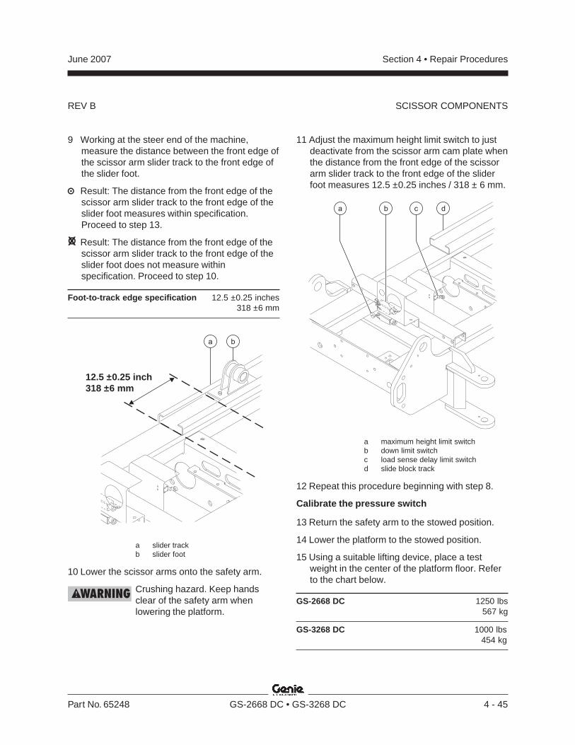
REV B
Section 4 • Repair ProceduresJune 2007
Part No. 65248 GS-2668 DC • GS-3268 DC 4 - 45
9 Working at the steer end of the machine,measure the distance between the front edge ofthe scissor arm slider track to the front edge ofthe slider foot.
Result: The distance from the front edge of thescissor arm slider track to the front edge of theslider foot measures within specification.Proceed to step 13.
Result: The distance from the front edge of thescissor arm slider track to the front edge of theslider foot does not measure withinspecification. Proceed to step 10.
Foot-to-track edge specification 12.5 ±0.25 inches318 ±6 mm
a b
12.5 ±0.25 inch318 ±6 mm
a slider trackb slider foot
10 Lower the scissor arms onto the safety arm.
Crushing hazard. Keep handsclear of the safety arm whenlowering the platform.
11 Adjust the maximum height limit switch to justdeactivate from the scissor arm cam plate whenthe distance from the front edge of the scissorarm slider track to the front edge of the sliderfoot measures 12.5 ±0.25 inches / 318 ± 6 mm.
a maximum height limit switchb down limit switchc load sense delay limit switchd slide block track
12 Repeat this procedure beginning with step 8.
Calibrate the pressure switch
13 Return the safety arm to the stowed position.
14 Lower the platform to the stowed position.
15 Using a suitable lifting device, place a testweight in the center of the platform floor. Referto the chart below.
GS-2668 DC 1250 lbs567 kg
GS-3268 DC 1000 lbs454 kg
SCISSOR COMPONENTS
REV B
Section 4 • Repair Procedures June 2007
4 - 46 GS-2668 DC • GS-3268 DC Part No. 65248
16 Secure the weight to the platform.
17 Fully raise the platform. Release the controls.
Result: The platform should stop raising atmaximum height. An alarm sounds. Themachine is functioning properly. Proceed tostep 26.
Result: The platform should stop raising atmaximum height. An alarm does not sound.The machine is not functioning properly.Proceed to step 18.
18 Lower the platform to approximately 10 ft / 3 mfrom the ground.
19 Lift the safety arm, move it to the center of thescissor arm and rotate down to a verticalposition.
20 Lower the scissor arms until the safety arm isnearly in contact with the scissor arms at bothends. Do not rest the scissor arms on thesafety arm.
Component damage hazard.Scissor arms can be damaged ifloaded unequally. Do not lower thescissor arms onto the safety armwith test weight in the platform.
21 Remove the cover from the platform overloadsensor box.
Note: The platform overload sensor box is locatedon the lift cylinder.
22 Turn the platform overload pressure switch 1/12
turn (half-flat) in a counter-clockwise direction.
23 Return the safety arm to the stowed position.
24 Lower the platform to the stowed position.
25 Repeat this procedure beginning with step 17.
Calibrate the load sense delay limit switch
26 Activate the auxiliary lowering function andlower the platform approximately 5 ft / 1.5 m.
27 Push in the red Emergency Stop button to theoff position at the ground controls.
28 Pull out the red Emergency Stop button to theon position at the ground controls.
29 Lower the platform to the stowed position.
Result: The platform stops lowering one time atapproximately 7 ft / 2 m. After releasing thecontrols for 4 to 6 seconds, the platform shouldlower to the stowed position. The machine isfunctioning properly. Proceed to step 36.
Result: The platform stops lowering two timesat approximately 7 ft / 2 m. After stopping forthe second time, the platform should lower tothe stowed position. The machine is notfunctioning properly. Proceed to step 30.
30 Raise the platform approximately 10 ft / 3 mfrom the ground.
31 Lift the safety arm, move it to the center of thescissor arm and rotate down to a verticalposition.
32 Lower the scissor arms until the safety arm isnearly in contact with the scissor arms at bothends of the safety arm. Do not rest the scissorarms on the safety arm.
Component damage hazard.Scissor arms can be damaged ifloaded unequally. Do not lower thescissor arms onto the safety armwith test weight in the platform.
33 For a point of reference, mark the outline of theload sense delay limit switch onto the side ofthe limit switch mount.
SCISSOR COMPONENTS
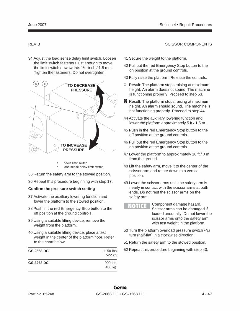
REV B
Section 4 • Repair ProceduresJune 2007
Part No. 65248 GS-2668 DC • GS-3268 DC 4 - 47
34 Adjust the load sense delay limit switch. Loosenthe limit switch fasteners just enough to movethe limit switch downwards 1/16 inch / 1.5 mm.Tighten the fasteners. Do not overtighten.
TO DECREASEPRESSURE
TO INCREASEPRESSURE
ba
a down limit switchb load sense delay limit switch
35 Return the safety arm to the stowed position.
36 Repeat this procedure beginning with step 17.
Confirm the pressure switch setting
37 Activate the auxiliary lowering function andlower the platform to the stowed position.
38 Push in the red Emergency Stop button to theoff position at the ground controls.
39 Using a suitable lifting device, remove theweight from the platform.
40 Using a suitable lifting device, place a testweight in the center of the platform floor. Referto the chart below.
GS-2668 DC 1150 lbs522 kg
GS-3268 DC 900 lbs408 kg
41 Secure the weight to the platform.
42 Pull out the red Emergency Stop button to theon position at the ground controls.
43 Fully raise the platform. Release the controls.
Result: The platform stops raising at maximumheight. An alarm does not sound. The machineis functioning properly. Proceed to step 53.
Result: The platform stops raising at maximumheight. An alarm should sound. The machine isnot functioning properly. Proceed to step 44.
44 Activate the auxiliary lowering function andlower the platform approximately 5 ft / 1.5 m.
45 Push in the red Emergency Stop button to theoff position at the ground controls.
46 Pull out the red Emergency Stop button to theon position at the ground controls.
47 Lower the platform to approximately 10 ft / 3 mfrom the ground.
48 Lift the safety arm, move it to the center of thescissor arm and rotate down to a verticalposition.
49 Lower the scissor arms until the safety arm isnearly in contact with the scissor arms at bothends. Do not rest the scissor arms on thesafety arm.
Component damage hazard.Scissor arms can be damaged ifloaded unequally. Do not lower thescissor arms onto the safety armwith test weight in the platform.
50 Turn the platform overload pressure switch 1/12
turn (half-flat) in a clockwise direction.
51 Return the safety arm to the stowed position.
52 Repeat this procedure beginning with step 43.
SCISSOR COMPONENTS
REV B
Section 4 • Repair Procedures June 2007
4 - 48 GS-2668 DC • GS-3268 DC Part No. 65248
Confirm the load sense delay limit switchheight
53 Lower the platform.
Result: The platform stops lowering atapproximately 7 ft / 2 m. An alarm does notsound. The machine is functioning properly.Proceed to step 63.
Result: The platform stops lowering atapproximately 7 ft / 2 m. An alarm sounds. Themachine is not functioning properly.Proceed to step 54.
54 Activate the auxiliary lowering function andlower the platform to the stowed position.
55 Push in the red Emergency Stop button to theoff position at the ground controls.
56 Pull out the red Emergency Stop button to theon position at the ground controls.
57 Raise the platform approximately 10 ft / 3 mfrom the ground.
58 Lift the safety arm, move it to the center of thescissor arm and rotate down to a verticalposition.
59 Lower the scissor arms until the safety arm isnearly in contact with the scissor arms at bothends of the safety arm. Do not rest the scissorarms on the safety arm.
Component damage hazard.Scissor arms can be damaged ifloaded unequally. Do not lower thescissor arms onto the safety armwith test weight in the platform.
60 Adjust the load sense delay limit switch. Loosenthe limit switch fasteners just enough to movethe limit switch upwards 1/16 inch / 1.5 mm.Tighten the fasteners. Do not overtighten.
Note: When the load sense delay limit switch isadjusted, it may be necessary to adjust the downlimit switch. If the machine stops at two separatetimes when lowering the platform, set the safetyarm and move the down limit switch in an upwardsdirection the same distance as the load sensedelay limit switch was moved.
61 Return the safety arm to the stowed position.
62 Repeat this procedure beginning with step 43.
63 Lower the platform to the stowed position andremove the test weight.
64 Raise the platform approximately 10 ft / 3 mfrom the ground.
65 Lift the safety arm, move it to the center of thescissor arm and rotate down to a verticalposition.
66 Lower the scissor arms onto the safety arm.
Crushing hazard. Keep handsclear of the safety arm whenlowering the platform.
67 Install the cover onto the platform overloadpressure switch box and tighten the fasteners.Do not overtighten.
68 Apply Sentry Seal® to one of the fastenerssecuring the cover onto the platform overloadpressure switch box.
69 Raise the platform slightly.
70 Return the safety arm to the stowed position.
71 Lower the platform to the stowed position.
72 Perform the function tests. Refer to theOperator's Manual.
SCISSOR COMPONENTS
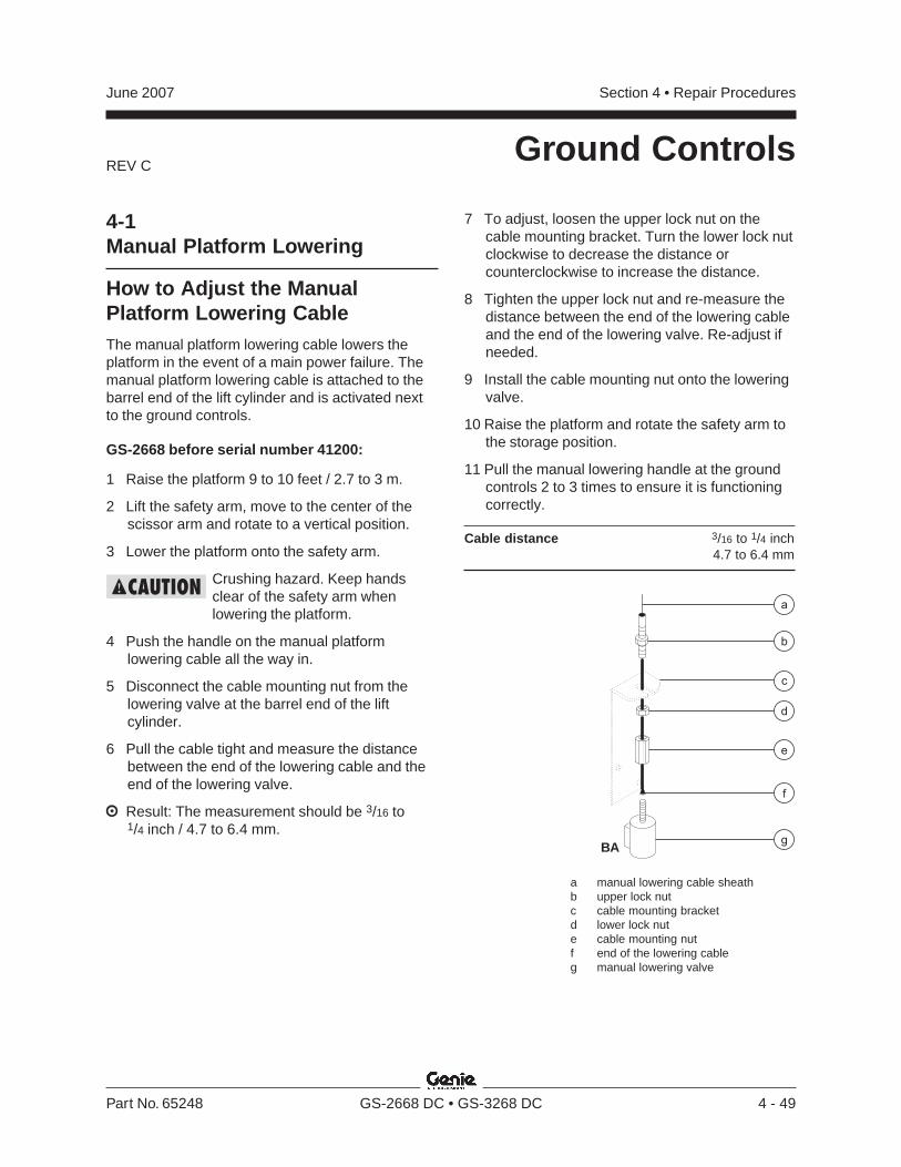
REV C
Section 4 • Repair ProceduresJune 2007
Part No. 65248 GS-2668 DC • GS-3268 DC 4 - 49
Ground Controls
4-1Manual Platform Lowering
How to Adjust the ManualPlatform Lowering CableThe manual platform lowering cable lowers theplatform in the event of a main power failure. Themanual platform lowering cable is attached to thebarrel end of the lift cylinder and is activated nextto the ground controls.
GS-2668 before serial number 41200:
1 Raise the platform 9 to 10 feet / 2.7 to 3 m.
2 Lift the safety arm, move to the center of thescissor arm and rotate to a vertical position.
3 Lower the platform onto the safety arm.
Crushing hazard. Keep handsclear of the safety arm whenlowering the platform.
4 Push the handle on the manual platformlowering cable all the way in.
5 Disconnect the cable mounting nut from thelowering valve at the barrel end of the liftcylinder.
6 Pull the cable tight and measure the distancebetween the end of the lowering cable and theend of the lowering valve.
Result: The measurement should be 3/16 to1/4 inch / 4.7 to 6.4 mm.
7 To adjust, loosen the upper lock nut on thecable mounting bracket. Turn the lower lock nutclockwise to decrease the distance orcounterclockwise to increase the distance.
8 Tighten the upper lock nut and re-measure thedistance between the end of the lowering cableand the end of the lowering valve. Re-adjust ifneeded.
9 Install the cable mounting nut onto the loweringvalve.
10 Raise the platform and rotate the safety arm tothe storage position.
11 Pull the manual lowering handle at the groundcontrols 2 to 3 times to ensure it is functioningcorrectly.
Cable distance 3/16 to 1/4 inch4.7 to 6.4 mm
a manual lowering cable sheathb upper lock nutc cable mounting bracketd lower lock nute cable mounting nutf end of the lowering cableg manual lowering valve
a
BA
b
c
d
e
f
g
REV C
Section 4 • Repair Procedures June 2007
4 - 50 GS-2668 DC • GS-3268 DC Part No. 65248
GROUND CONTROLS
GS-2668 after serial number 41199 andGS-3268 (all)
In the event of a main power failure, activating thefunction enable and manual platform loweringbuttons at the ground controls will lower theplatform. There is no adjustment required.
Before serial number 41830, two 6V DC batteriesare wired in series to supply power for the manualplatform lowering function. These batteries arelocated behind the ground control panel.
After serial number 41829, these batteries are nolonger used. Instead, onboard batteries supplypower for the manual platform lowering function.
How to Replace the ManualPlatform Lowering BatteriesBefore serial number 41830:
1 Remove the cover from the ground controlpanel.
2 Tag and disconnect the wires from the batteryto be removed.
3 Remove the battery from the machine.
4 Install the new battery and connect the wires.
5 Install the ground control cover.
4-2Toggle SwitchesSee 1-5, Toggle Switches.
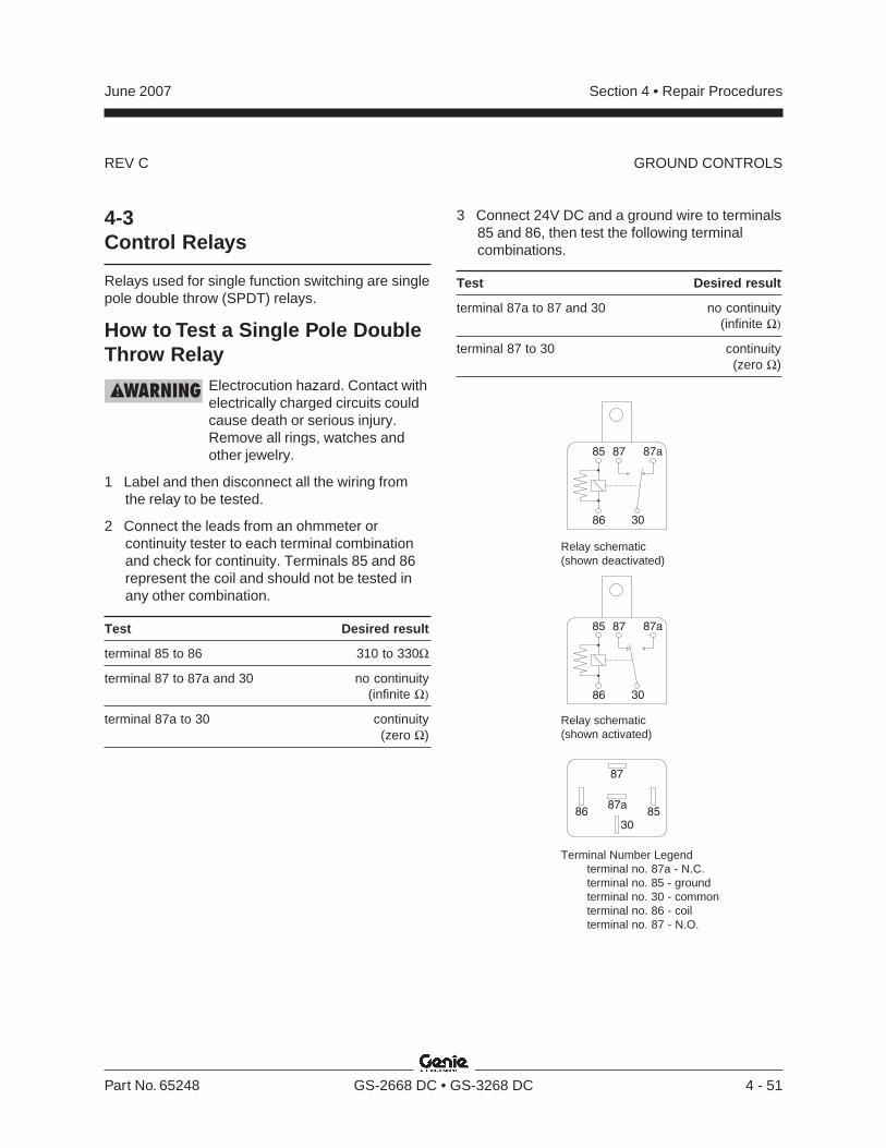
REV C
Section 4 • Repair ProceduresJune 2007
Part No. 65248 GS-2668 DC • GS-3268 DC 4 - 51
4-3Control Relays
Relays used for single function switching are singlepole double throw (SPDT) relays.
How to Test a Single Pole DoubleThrow Relay
Electrocution hazard. Contact withelectrically charged circuits couldcause death or serious injury.Remove all rings, watches andother jewelry.
1 Label and then disconnect all the wiring fromthe relay to be tested.
2 Connect the leads from an ohmmeter orcontinuity tester to each terminal combinationand check for continuity. Terminals 85 and 86represent the coil and should not be tested inany other combination.
Test Desired result
terminal 85 to 86 310 to 330Ω
terminal 87 to 87a and 30 no continuity(infinite Ω)
terminal 87a to 30 continuity(zero Ω)
3 Connect 24V DC and a ground wire to terminals85 and 86, then test the following terminalcombinations.
Test Desired result
terminal 87a to 87 and 30 no continuity(infinite Ω)
terminal 87 to 30 continuity(zero Ω)
Relay schematic(shown deactivated)
85
87
8687a
30
30
87a87
86
85
30
87a87
86
85
Relay schematic(shown activated)
Terminal Number Legendterminal no. 87a - N.C.terminal no. 85 - groundterminal no. 30 - commonterminal no. 86 - coilterminal no. 87 - N.O.
GROUND CONTROLS
REV C
Section 4 • Repair Procedures June 2007
4 - 52 GS-2668 DC • GS-3268 DC Part No. 65248
GROUND CONTROLS
4-4Tilt Level Sensor
The Electronic Control Module (ECM) isprogrammed to deactivate the lift and drivefunctions and activate an alarm when a signal isreceived from the level sensor.
The tilt alarm sounds when the incline of thechassis exceeds 2° to the side, 3° to the front or 5°to the rear.
How to Install and Calibrate theLevel Sensor(before serial number 41754)
Tip-over hazard. Failure to installor calibrate the level sensor asinstructed could result in themachine tipping over causingdeath or serious injury. Do notinstall or calibrate the level sensorother than specified in thisprocedure.
Note: Perform this procedure with the machine ona firm, level surface that is free of obstructions.Use a digital level to confirm.
1 Remove the platform controls from the platform.
2 Block the wheels at the non-steer end of themachine.
3 Center a lifting jack under the drive chassis atthe steer end of the machine.
4 Raise the machine approximately4 inches / 10 cm.
5 Place a 1.27 x 10 x 10 inch / 3.23 x 25 x 25 cmthick steel block under both wheels at the steerend of the machine.
6 Lower the machine onto the blocks.
7 Turn the key switch to platform control and pullout the red Emergency Stop buttons to the onposition at both the ground and platformcontrols.
8 Before serial number 41137: Raise theplatform at least 12 feet / 3.6 m.
Result - ANSI and CSA models: The tilt alarmwill sound at 180 beeps per minute.
Result - CE and Australian models: The drivefunction and the lift function will not operate andthe tilt alarm will sound at 180 beeps perminute.
After serial number 41136: Raise the platformat least 12 feet / 3.6 m.
Result - The drive function and the lift functionwill not operate and the tilt alarm will sound at180 beeps per minute.
If you are not installing a new level sensor,proceed to step 21.
9 Push in the red Emergency Stop button to theoff position at the platform controls.
10 Before serial number 41200: Remove theground control panel retaining fasteners andopen the panel. Locate the level sensor behindthe ground control panel.
11 After serial number 41199: Lift the safety arm,move to the center of the scissor arm androtate to a vertical position.
12 Lower the platform onto the safety arm.
Crushing hazard. Keep handsclear of the safety arm whenlowering the platform.
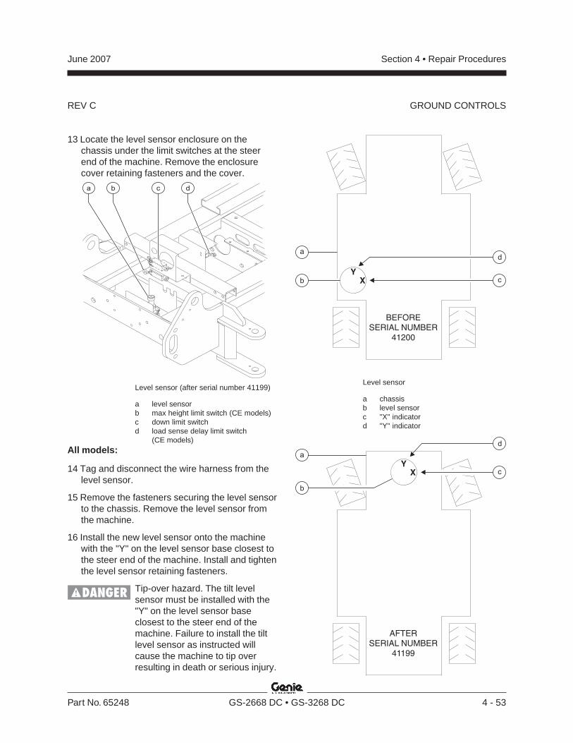
REV C
Section 4 • Repair ProceduresJune 2007
Part No. 65248 GS-2668 DC • GS-3268 DC 4 - 53
GROUND CONTROLS
13 Locate the level sensor enclosure on thechassis under the limit switches at the steerend of the machine. Remove the enclosurecover retaining fasteners and the cover.
Level sensor (after serial number 41199)
a level sensorb max height limit switch (CE models)c down limit switchd load sense delay limit switch
(CE models)All models:
14 Tag and disconnect the wire harness from thelevel sensor.
15 Remove the fasteners securing the level sensorto the chassis. Remove the level sensor fromthe machine.
16 Install the new level sensor onto the machinewith the "Y" on the level sensor base closest tothe steer end of the machine. Install and tightenthe level sensor retaining fasteners.
Tip-over hazard. The tilt levelsensor must be installed with the"Y" on the level sensor baseclosest to the steer end of themachine. Failure to install the tiltlevel sensor as instructed willcause the machine to tip overresulting in death or serious injury.
a dcb
Level sensor
a chassisb level sensorc "X" indicatord "Y" indicator
XY
b
d
c
a
BEFORESERIAL NUMBER
41200
AFTERSERIAL NUMBER
41199
d
c
b
XY
a
REV C
Section 4 • Repair Procedures June 2007
4 - 54 GS-2668 DC • GS-3268 DC Part No. 65248
GROUND CONTROLS
17 Connect the wire harness to the level sensor.
18 Pull out the red Emergency Stop button to theon position at the platform controls.
19 Tighten the level sensor adjusting fastenersuntil the bubble in the top of the level sensor iscentered in the circles.
Note: Be sure there are threads showing throughthe top of the adjusting fasteners.
Result: The tilt sensor alarm should not sound.
20 After serial number 41199: Raise the platformand rotate the safety arm to the stowedposition.
21 Lower the platform to the stowed position.
22 Raise the machine slightly.
23 Remove the blocks from under both wheels.
24 Lower the machine and remove the jack.
25 Remove the blocks from the wheels at thenon-steer end of the machine.
26 Block the wheels at the steer end of themachine.
27 Center a lifting jack under the drive chassis atthe non-steer end of the machine.
28 Raise the machine approximately8 inches / 20 cm.
29 Place a 6.77 x 10 x 10 inch / 26.4 x 25 x 25 cmthick steel block under both wheels at thenon-steer end of the machine.
30 Lower the machine onto the blocks.
31 Before serial number 41137: Raise theplatform at least 12 feet / 3.6 m.
Result - ANSI and CSA models: The tilt alarmwill sound at 180 beeps per minute.
Result - CE and Australian models: The drivefunction and the lift function will not operate andthe tilt alarm will sound at 180 beeps perminute.
Result: If the tilt sensor alarm does not sound,adjust the tilt level sensor until the alarm justbegins to sound OR the down limit switch mayneed to be adjusted.
After serial number 41136: Raise the platformat least 12 feet / 3.6 m.
Result - The drive function and the lift functionwill not operate and the tilt alarm will sound at180 beeps per minute.
Result: If the tilt sensor alarm does not sound,adjust the tilt level sensor until the alarm justbegins to sound OR the down limit switch mayneed to be adjusted.
32 Lower the platform to the stowed position.
33 Raise the machine slightly.
34 Remove the blocks from under both wheels.
35 Lower the machine and remove the jack.
36 Remove the blocks from the wheels at the steerend of the machine.
37 Center a lifting jack under the drive chassis atthe ground controls side of the machine.
38 Raise the machine approximately4 inches / 10 cm.
REV C
Section 4 • Repair ProceduresJune 2007
Part No. 65248 GS-2668 DC • GS-3268 DC 4 - 55
GROUND CONTROLS
39 Place a 1.94 x 10 x 10 inch / 4.93 x 25 x 25 cmthick steel block under both wheels at theground controls side of the machine.
40 Lower the machine onto the blocks.
41 Before serial number 41137: Raise theplatform at least 12 feet / 3.6 m.
Result: The tilt alarm does not sound and allfunctions will operate. Proceed to step 43.
Result - ANSI and CSA models: The tilt alarmsounds at 180 beeps per minute. Proceed tostep 42.
Result - CE and Australian models: The drivefunction and the lift function will not operate andthe tilt alarm sounds at 180 beeps per minute.Proceed to step 42.
After serial number 41136: Raise the platformat least 12 feet / 3.6 m.
Result: The tilt alarm does not sound and allfunctions will operate. Proceed to step 43.
Result - The drive function and the lift functionwill not operate and the tilt alarm sounds at 180beeps per minute. Proceed to step 42.
42 Turn the level sensor adjusting nuts just untilthe level sensor alarm does not sound.
43 Lower the platform to the stowed position.
44 Raise the machine slightly.
45 Remove the blocks from under both wheels.
46 Lower the machine and remove the jack.
47 Center a lifting jack under the drive chassis atthe engine side of the machine.
48 Raise the machine approximately4 inches / 10 cm.
49 Place a 2.25 x 10 x 10 inch / 5.72 x 25 x 25 cmthick steel block under both wheels at theground controls side of the machine.
50 Lower the machine onto the blocks.
51 Before serial number 41137: Raise theplatform at least 12 feet / 3.6 m.
Result - ANSI and CSA models: The tilt alarmwill sound at 180 beeps per minute.
Result - CE and Australian models: The drivefunction and the lift function will not operate andthe tilt alarm will sound at 180 beeps perminute.
Result: If the tilt sensor alarm does not sound,adjust the tilt level sensor until the alarm justbegins to sound OR the down limit switch mayneed to be adjusted.
After serial number 41136: Raise the platformat least 12 feet / 3.6 m.
Result - The drive function and the lift functionwill not operate and the tilt alarm will sound at180 beeps per minute.
Result: If the tilt sensor alarm does not sound,adjust the tilt level sensor until the alarm justbegins to sound OR the down limit switch mayneed to be adjusted.
52 Lower the platform to the stowed position.
53 Push in the red Emergency Stop button to theoff position at both the ground and platformcontrols.
54 Turn the key switch to the off position.
55 Raise the machine slightly.
56 Remove the blocks from under both wheels.
57 Lower the machine and remove the jack.
58 Before serial number 41200: Close theground control panel. Install and securelytighten the retaining fasteners. Do not overtighten.
After serial number 41199: Install the coveronto the level sensor enclosure. Install andsecurely tighten the retaining fasteners. Do notover tighten.
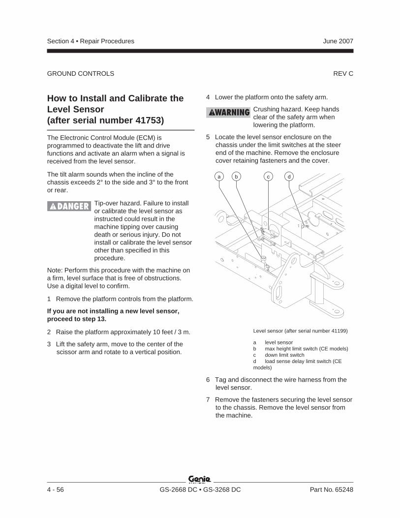
REV C
Section 4 • Repair Procedures June 2007
4 - 56 GS-2668 DC • GS-3268 DC Part No. 65248
GROUND CONTROLS
How to Install and Calibrate theLevel Sensor(after serial number 41753)
The Electronic Control Module (ECM) isprogrammed to deactivate the lift and drivefunctions and activate an alarm when a signal isreceived from the level sensor.
The tilt alarm sounds when the incline of thechassis exceeds 2° to the side and 3° to the frontor rear.
Tip-over hazard. Failure to installor calibrate the level sensor asinstructed could result in themachine tipping over causingdeath or serious injury. Do notinstall or calibrate the level sensorother than specified in thisprocedure.
Note: Perform this procedure with the machine ona firm, level surface that is free of obstructions.Use a digital level to confirm.
1 Remove the platform controls from the platform.
If you are not installing a new level sensor,proceed to step 13.
2 Raise the platform approximately 10 feet / 3 m.
3 Lift the safety arm, move to the center of thescissor arm and rotate to a vertical position.
4 Lower the platform onto the safety arm.
Crushing hazard. Keep handsclear of the safety arm whenlowering the platform.
5 Locate the level sensor enclosure on thechassis under the limit switches at the steerend of the machine. Remove the enclosurecover retaining fasteners and the cover.
Level sensor (after serial number 41199)
a level sensorb max height limit switch (CE models)c down limit switchd load sense delay limit switch (CEmodels)
6 Tag and disconnect the wire harness from thelevel sensor.
7 Remove the fasteners securing the level sensorto the chassis. Remove the level sensor fromthe machine.
a dcb

REV C
Section 4 • Repair ProceduresJune 2007
Part No. 65248 GS-2668 DC • GS-3268 DC 4 - 57
GROUND CONTROLS
8 Install the new level sensor onto the machinewith the "Y" on the level sensor base closest tothe steer end of the machine. Install and tightenthe level sensor retaining fasteners.
Tip-over hazard. The tilt levelsensor must be installed with the"Y" on the level sensor baseclosest to the steer end of themachine. Failure to install the tiltlevel sensor as instructed willcause the machine to tip overresulting in death or serious injury.
9 Connect the wire harness to the level sensor.
10 Turn the key switch to platform control and pullout the red Emergency Stop buttons to the onposition at both the ground and platformcontrols.
11 Tighten the level sensor adjusting fastenersuntil the bubble in the top of the level sensor iscentered in the circles.
Note: Be sure there are threads showing throughthe top of the adjusting fasteners.
Result: The tilt sensor alarm should not sound.
12 Raise the platform and rotate the safety arm tothe stowed position.
13 Lower the platform to the stowed position.
14 Center a lifting jack under the drive chassis atthe ground controls side of the machine.
15 Raise the machine approximately4 inches / 10 cm.
Level sensor
a chassisb level sensorc "X" indicatord "Y" indicator
16 Place a 1.94 x 10 x 10 inch / 4.93 x 25 x 25 cmthick steel block under both wheels at theground controls side of the machine.
17 Lower the machine onto the blocks.
d
c
b
XY
a
REV C
Section 4 • Repair Procedures June 2007
4 - 58 GS-2668 DC • GS-3268 DC Part No. 65248
GROUND CONTROLS
18 Raise the platform at least 12 feet / 3.6 m.
Result: The tilt alarm does not sound and allfunctions will operate. Proceed to step 20.
Result - The drive function and the lift functionwill not operate and the tilt alarm will sound at180 beeps per minute. Proceed to step 19.
19 Turn the level sensor adjusting nuts just untilthe level sensor alarm does not sound.
20 Lower the platform to the stowed position.
21 Raise the machine slightly.
22 Remove the blocks from under both wheels.
23 Lower the machine and remove the jack.
24 Center a lifting jack under the drive chassis atthe engine side of the machine.
25 Raise the machine approximately4 inches / 10 cm.
26 Place a 2.25 x 10 x 10 inch / 5.72 x 25 x 25 cmthick steel block under both wheels at theground controls side of the machine.
27 Lower the machine onto the blocks.
28 Raise the platform at least 12 feet / 3.6 m.
Result - The drive function and the lift functionwill not operate and the tilt alarm will sound at180 beeps per minute.
Result: If the tilt sensor alarm does not sound,adjust the tilt level sensor until the alarm justbegins to sound OR the down limit switch mayneed to be adjusted.
29 Lower the platform to the stowed position.
30 Push in the red Emergency Stop button to theoff position at both the ground and platformcontrols.
31 Turn the key switch to the off position.
32 Raise the machine slightly.
33 Remove the blocks from under both wheels.
34 Lower the machine and remove the jack.
35 Install the cover onto the level sensorenclosure. Install and securely tighten theretaining fasteners. Do not over tighten.
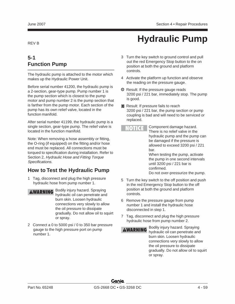
REV B
Section 4 • Repair ProceduresJune 2007
Part No. 65248 GS-2668 DC • GS-3268 DC 4 - 59
Hydraulic Pump
5-1Function Pump
The hydraulic pump is attached to the motor whichmakes up the Hydraulic Power Unit.
Before serial number 41200, the hydraulic pump isa 2-section, gear-type pump. Pump number 1 isthe pump section which is closest to the pumpmotor and pump number 2 is the pump section thatis farther from the pump motor. Each section of thepump has its own relief valve, located in thefunction manifold.
After serial number 41199, the hydraulic pump is asingle section, gear-type pump. The relief valve islocated in the function manifold.
Note: When removing a hose assembly or fitting,the O-ring (if equipped) on the fitting and/or hoseend must be replaced. All connections must betorqued to specification during installation. Refer toSection 2, Hydraulic Hose and Fitting TorqueSpecifications.
How to Test the Hydraulic Pump1 Tag, disconnect and plug the high pressure
hydraulic hose from pump number 1.
Bodily injury hazard. Sprayinghydraulic oil can penetrate andburn skin. Loosen hydraulicconnections very slowly to allowthe oil pressure to dissipategradually. Do not allow oil to squirtor spray.
2 Connect a 0 to 5000 psi / 0 to 350 bar pressuregauge to the high pressure port on pumpnumber 1.
3 Turn the key switch to ground control and pullout the red Emergency Stop button to the onposition at both the ground and platformcontrols.
4 Activate the platform up function and observethe reading on the pressure gauge.
Result: If the pressure gauge reads3200 psi / 221 bar, immediately stop. The pumpis good.
Result: If pressure fails to reach3200 psi / 221 bar, the pump section or pumpcoupling is bad and will need to be serviced orreplaced.
Component damage hazard.There is no relief valve in thehydraulic pump and the pump canbe damaged if the pressure isallowed to exceed 3200 psi / 221bar.When testing the pump, activatethe pump in one second intervalsuntil 3200 psi / 221 bar isconfirmed.Do not over-pressurize the pump.
5 Turn the key switch to the off position and pushin the red Emergency Stop button to the offposition at both the ground and platformcontrols.
6 Remove the pressure gauge from pumpnumber 1 and install the hydraulic hosedisconnected in step 1.
7 Tag, disconnect and plug the high pressurehydraulic hose from pump number 2.
Bodily injury hazard. Sprayinghydraulic oil can penetrate andburn skin. Loosen hydraulicconnections very slowly to allowthe oil pressure to dissipategradually. Do not allow oil to squirtor spray.
REV B
Section 4 • Repair Procedures June 2007
4 - 60 GS-2668 DC • GS-3268 DC Part No. 65248
8 Connect a 0 to 5000 psi / 0 to 350 bar pressuregauge to the high pressure port on pumpnumber 2.
9 Turn the key switch to ground control and pullout the red Emergency Stop button to the onposition at both the ground and platformcontrols.
10 Activate the platform up function and observethe reading on the pressure gauge.
Result: If the pressure gauge reads3200 psi / 221 bar, immediately stop. The pumpis good.
Result: If pressure fails to reach3200 psi / 221 bar, the pump section or pumpcoupling is bad and will need to be serviced orreplaced.
11 Turn the key switch to the off position and pushin the red Emergency Stop button to the offposition at both the ground and platformcontrols.
12 Remove the pressure gauge from pumpnumber 2 and install the hydraulic hosedisconnected in step 7.
Bodily injury hazard. Sprayinghydraulic oil can penetrate andburn skin. Loosen hydraulicconnections very slowly to allowthe oil pressure to dissipategradually. Do not allow oil to squirtor spray.
HYDRAULIC PUMP
How to Remove theHydraulic Pump1 Tag, disconnect and plug the hydraulic hoses
from the pump.
Bodily injury hazard. Sprayinghydraulic oil can penetrate andburn skin. Loosen hydraulicconnections very slowly to allowthe oil pressure to dissipategradually. Do not allow oil to squirtor spray.
2 Remove the pump mounting bolts. Carefullyremove the pump.
Tip-over hazard. If replacing thehydraulic pump, it is critical toreturn the lift speed and raiseddrive speed settings to originalfactory specifications. Themachine may become unstableand tip over, resulting in death orserious injury.
Note: If the machine raised drive speed is exceedsspecifications, refer to the Maintenance procedureB-9, Test the Drive Speed - Raised Position toconfirm the speed, and refer to the Repairprocedure 1-3, Controller Adjustments to correctthe raised drive speed percentage settings.
Section 4 • Repair ProceduresJune 2007
Part No. 65248 GS-2668 DC • GS-3268 DC 4 - 61
This page intentionally left blank.
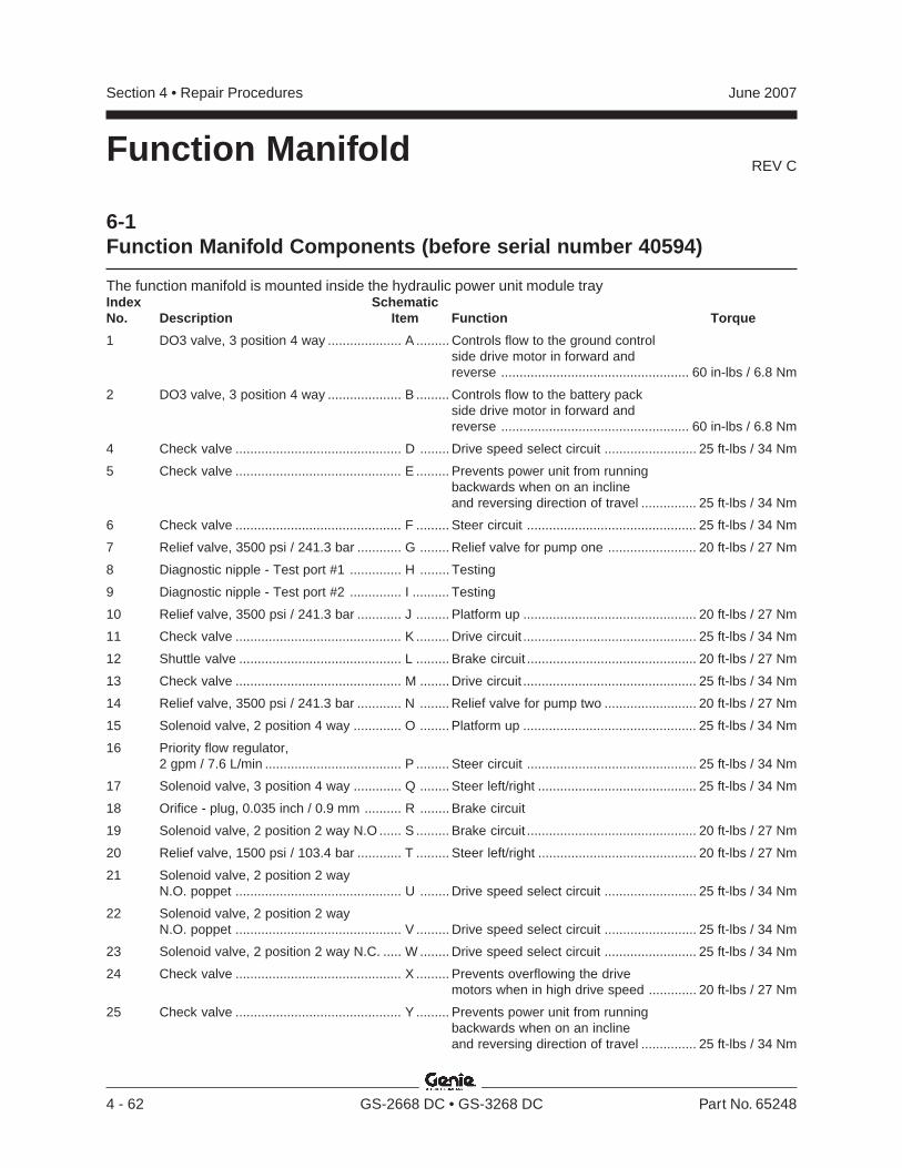
REV C
Section 4 • Repair Procedures June 2007
4 - 62 GS-2668 DC • GS-3268 DC Part No. 65248
Function Manifold
Index SchematicNo. Description Item Function Torque
1 DO3 valve, 3 position 4 way .................... A ......... Controls flow to the ground controlside drive motor in forward andreverse ................................................... 60 in-lbs / 6.8 Nm
2 DO3 valve, 3 position 4 way .................... B ......... Controls flow to the battery packside drive motor in forward andreverse ................................................... 60 in-lbs / 6.8 Nm
4 Check valve ............................................. D ........ Drive speed select circuit ......................... 25 ft-lbs / 34 Nm
5 Check valve ............................................. E ......... Prevents power unit from runningbackwards when on an inclineand reversing direction of travel ............... 25 ft-lbs / 34 Nm
6 Check valve ............................................. F ......... Steer circuit .............................................. 25 ft-lbs / 34 Nm
7 Relief valve, 3500 psi / 241.3 bar ............ G ........ Relief valve for pump one ........................ 20 ft-lbs / 27 Nm
8 Diagnostic nipple - Test port #1 .............. H ........ Testing
9 Diagnostic nipple - Test port #2 .............. I .......... Testing
10 Relief valve, 3500 psi / 241.3 bar ............ J ......... Platform up ............................................... 20 ft-lbs / 27 Nm
11 Check valve ............................................. K ......... Drive circuit ............................................... 25 ft-lbs / 34 Nm
12 Shuttle valve ............................................ L ......... Brake circuit .............................................. 20 ft-lbs / 27 Nm
13 Check valve ............................................. M ........ Drive circuit ............................................... 25 ft-lbs / 34 Nm
14 Relief valve, 3500 psi / 241.3 bar ............ N ........ Relief valve for pump two ......................... 20 ft-lbs / 27 Nm
15 Solenoid valve, 2 position 4 way ............. O ........ Platform up ............................................... 25 ft-lbs / 34 Nm
16 Priority flow regulator,2 gpm / 7.6 L/min ..................................... P ......... Steer circuit .............................................. 25 ft-lbs / 34 Nm
17 Solenoid valve, 3 position 4 way ............. Q ........ Steer left/right ........................................... 25 ft-lbs / 34 Nm
18 Orifice - plug, 0.035 inch / 0.9 mm .......... R ........ Brake circuit
19 Solenoid valve, 2 position 2 way N.O ...... S ......... Brake circuit .............................................. 20 ft-lbs / 27 Nm
20 Relief valve, 1500 psi / 103.4 bar ............ T ......... Steer left/right ........................................... 20 ft-lbs / 27 Nm
21 Solenoid valve, 2 position 2 wayN.O. poppet ............................................. U ........ Drive speed select circuit ......................... 25 ft-lbs / 34 Nm
22 Solenoid valve, 2 position 2 wayN.O. poppet ............................................. V ......... Drive speed select circuit ......................... 25 ft-lbs / 34 Nm
23 Solenoid valve, 2 position 2 way N.C. ..... W ........ Drive speed select circuit ......................... 25 ft-lbs / 34 Nm
24 Check valve ............................................. X ......... Prevents overflowing the drivemotors when in high drive speed ............. 20 ft-lbs / 27 Nm
25 Check valve ............................................. Y ......... Prevents power unit from runningbackwards when on an inclineand reversing direction of travel ............... 25 ft-lbs / 34 Nm
6-1Function Manifold Components (before serial number 40594)
The function manifold is mounted inside the hydraulic power unit module tray
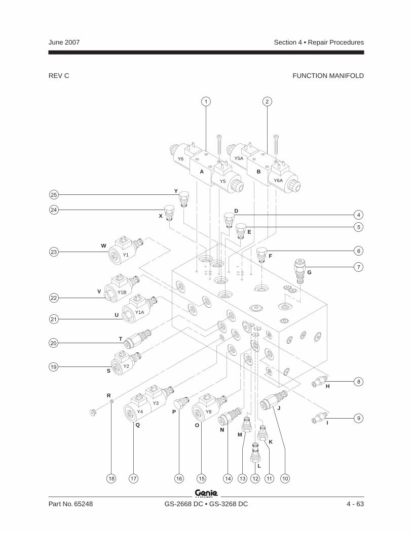
REV C
Section 4 • Repair ProceduresJune 2007
Part No. 65248 GS-2668 DC • GS-3268 DC 4 - 63
FUNCTION MANIFOLD
BA
D
E
G
F
H
I
J
K
L
M
O
P
R
Q
S
T
U
W
X
Y
Y6
Y8Y4
Y2
Y1A
Y1B
Y1
Y3
Y5
Y5A
Y6A
22
21
121415 13 11 1017 16
1 2
24
25
19
18
23
20
6
5
4
7
8
9
V
N
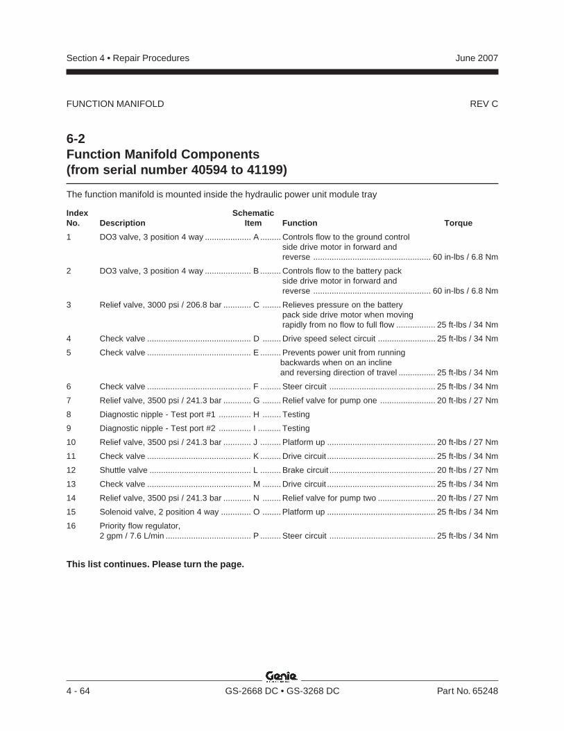
REV C
Section 4 • Repair Procedures June 2007
4 - 64 GS-2668 DC • GS-3268 DC Part No. 65248
FUNCTION MANIFOLD
Index SchematicNo. Description Item Function Torque
1 DO3 valve, 3 position 4 way .................... A ......... Controls flow to the ground controlside drive motor in forward andreverse ................................................... 60 in-lbs / 6.8 Nm
2 DO3 valve, 3 position 4 way .................... B ......... Controls flow to the battery packside drive motor in forward andreverse ................................................... 60 in-lbs / 6.8 Nm
3 Relief valve, 3000 psi / 206.8 bar ............ C ........ Relieves pressure on the batterypack side drive motor when movingrapidly from no flow to full flow ................. 25 ft-lbs / 34 Nm
4 Check valve ............................................. D ........ Drive speed select circuit ......................... 25 ft-lbs / 34 Nm
5 Check valve ............................................. E ......... Prevents power unit from runningbackwards when on an inclineand reversing direction of travel ................ 25 ft-lbs / 34 Nm
6 Check valve ............................................. F ......... Steer circuit .............................................. 25 ft-lbs / 34 Nm
7 Relief valve, 3500 psi / 241.3 bar ............ G ........ Relief valve for pump one ........................ 20 ft-lbs / 27 Nm
8 Diagnostic nipple - Test port #1 .............. H ........ Testing
9 Diagnostic nipple - Test port #2 .............. I .......... Testing
10 Relief valve, 3500 psi / 241.3 bar ............ J ......... Platform up ............................................... 20 ft-lbs / 27 Nm
11 Check valve ............................................. K ......... Drive circuit ............................................... 25 ft-lbs / 34 Nm
12 Shuttle valve ............................................ L ......... Brake circuit .............................................. 20 ft-lbs / 27 Nm
13 Check valve ............................................. M ........ Drive circuit ............................................... 25 ft-lbs / 34 Nm
14 Relief valve, 3500 psi / 241.3 bar ............ N ........ Relief valve for pump two ......................... 20 ft-lbs / 27 Nm
15 Solenoid valve, 2 position 4 way ............. O ........ Platform up ............................................... 25 ft-lbs / 34 Nm
16 Priority flow regulator,2 gpm / 7.6 L/min ..................................... P ......... Steer circuit .............................................. 25 ft-lbs / 34 Nm
This list continues. Please turn the page.
6-2Function Manifold Components(from serial number 40594 to 41199)
The function manifold is mounted inside the hydraulic power unit module tray

REV C
Section 4 • Repair ProceduresJune 2007
Part No. 65248 GS-2668 DC • GS-3268 DC 4 - 65
FUNCTION MANIFOLD
BA
C
D
E
G
F
H
I
J
K
L
M
O
P
R
Q
S
T
U
W
X
Y
Z
Y6
Y8Y4
Y2
Y1A
Y1B
Y1
Y3
Y5
Y5A
Y6A
22
21
121415 13 11 1017 16
1
24
25
26
19
18
23
20
2
6
5
4
3
7
8
9
V
N
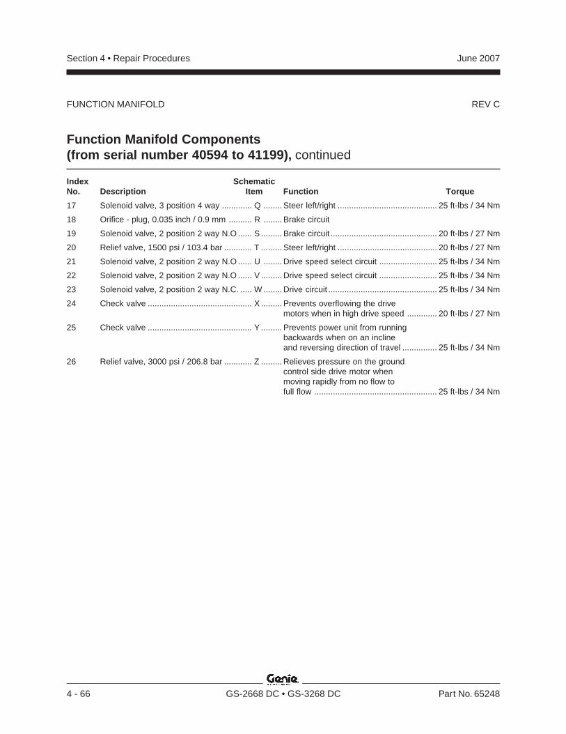
REV C
Section 4 • Repair Procedures June 2007
4 - 66 GS-2668 DC • GS-3268 DC Part No. 65248
Function Manifold Components(from serial number 40594 to 41199), continued
FUNCTION MANIFOLD
Index SchematicNo. Description Item Function Torque
17 Solenoid valve, 3 position 4 way ............. Q ........ Steer left/right ........................................... 25 ft-lbs / 34 Nm
18 Orifice - plug, 0.035 inch / 0.9 mm .......... R ........ Brake circuit
19 Solenoid valve, 2 position 2 way N.O ...... S ......... Brake circuit .............................................. 20 ft-lbs / 27 Nm
20 Relief valve, 1500 psi / 103.4 bar ............ T ......... Steer left/right ........................................... 20 ft-lbs / 27 Nm
21 Solenoid valve, 2 position 2 way N.O ...... U ........ Drive speed select circuit ......................... 25 ft-lbs / 34 Nm
22 Solenoid valve, 2 position 2 way N.O ...... V ......... Drive speed select circuit ......................... 25 ft-lbs / 34 Nm
23 Solenoid valve, 2 position 2 way N.C. ..... W ........ Drive circuit ............................................... 25 ft-lbs / 34 Nm
24 Check valve ............................................. X ......... Prevents overflowing the drivemotors when in high drive speed ............. 20 ft-lbs / 27 Nm
25 Check valve ............................................. Y ......... Prevents power unit from runningbackwards when on an inclineand reversing direction of travel ............... 25 ft-lbs / 34 Nm
26 Relief valve, 3000 psi / 206.8 bar ............ Z ......... Relieves pressure on the groundcontrol side drive motor whenmoving rapidly from no flow tofull flow ..................................................... 25 ft-lbs / 34 Nm
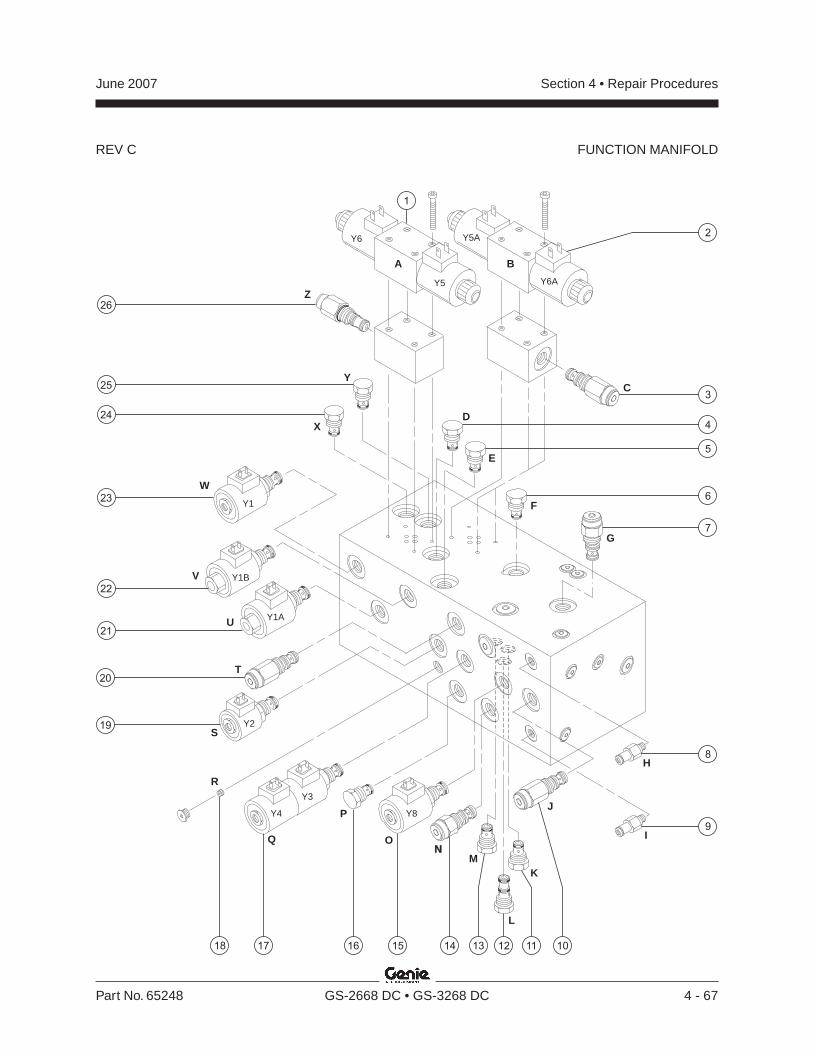
REV C
Section 4 • Repair ProceduresJune 2007
Part No. 65248 GS-2668 DC • GS-3268 DC 4 - 67
BA
C
D
E
G
F
H
I
J
K
L
M
O
P
R
Q
S
T
U
W
X
Y
Z
Y6
Y8Y4
Y2
Y1A
Y1B
Y1
Y3
Y5
Y5A
Y6A
22
21
121415 13 11 1017 16
1
24
25
26
19
18
23
20
2
6
5
4
3
7
8
9
V
N
FUNCTION MANIFOLD
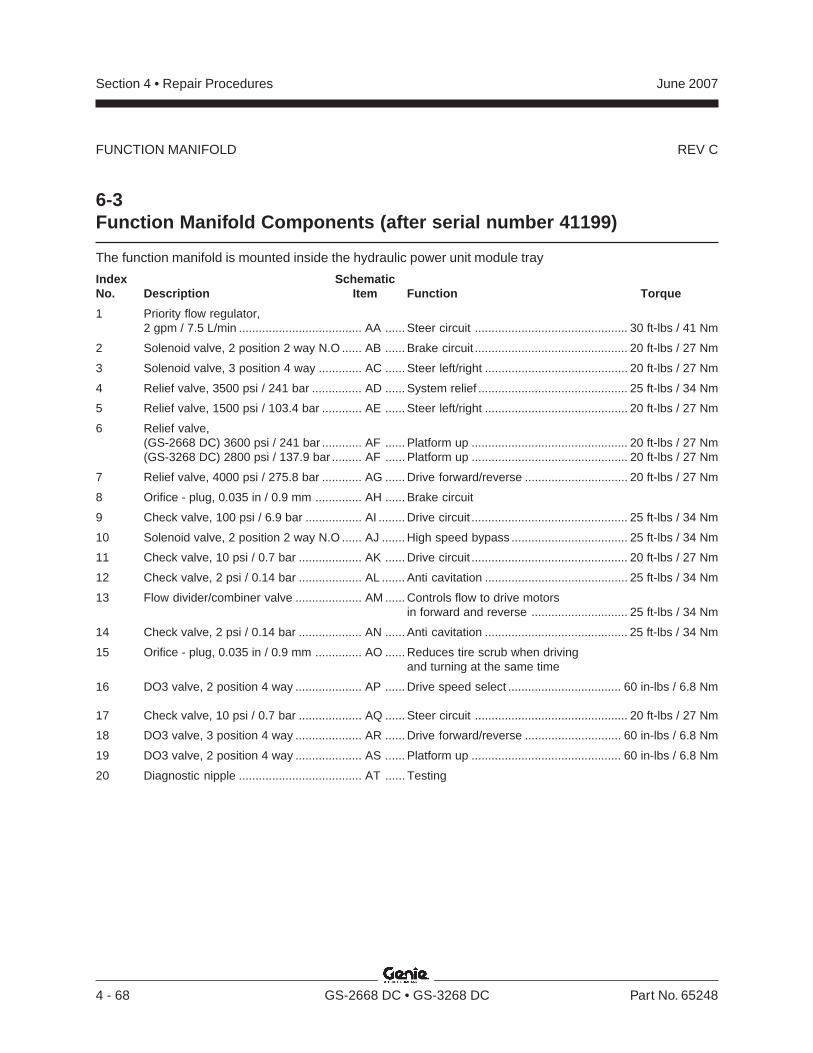
REV C
Section 4 • Repair Procedures June 2007
4 - 68 GS-2668 DC • GS-3268 DC Part No. 65248
6-3Function Manifold Components (after serial number 41199)
The function manifold is mounted inside the hydraulic power unit module tray
Index SchematicNo. Description Item Function Torque
1 Priority flow regulator,2 gpm / 7.5 L/min ..................................... AA ...... Steer circuit .............................................. 30 ft-lbs / 41 Nm
2 Solenoid valve, 2 position 2 way N.O ...... AB ...... Brake circuit .............................................. 20 ft-lbs / 27 Nm
3 Solenoid valve, 3 position 4 way ............. AC ...... Steer left/right ........................................... 20 ft-lbs / 27 Nm
4 Relief valve, 3500 psi / 241 bar ............... AD ...... System relief ............................................. 25 ft-lbs / 34 Nm
5 Relief valve, 1500 psi / 103.4 bar ............ AE ...... Steer left/right ........................................... 20 ft-lbs / 27 Nm
6 Relief valve,(GS-2668 DC) 3600 psi / 241 bar ............ AF ...... Platform up ............................................... 20 ft-lbs / 27 Nm(GS-3268 DC) 2800 psi / 137.9 bar ......... AF ...... Platform up ............................................... 20 ft-lbs / 27 Nm
7 Relief valve, 4000 psi / 275.8 bar ............ AG ...... Drive forward/reverse ............................... 20 ft-lbs / 27 Nm
8 Orifice - plug, 0.035 in / 0.9 mm .............. AH ...... Brake circuit
9 Check valve, 100 psi / 6.9 bar ................. AI ........ Drive circuit ............................................... 25 ft-lbs / 34 Nm
10 Solenoid valve, 2 position 2 way N.O ...... AJ ....... High speed bypass ................................... 25 ft-lbs / 34 Nm
11 Check valve, 10 psi / 0.7 bar ................... AK ...... Drive circuit ............................................... 20 ft-lbs / 27 Nm
12 Check valve, 2 psi / 0.14 bar ................... AL ....... Anti cavitation ........................................... 25 ft-lbs / 34 Nm
13 Flow divider/combiner valve .................... AM ...... Controls flow to drive motorsin forward and reverse ............................. 25 ft-lbs / 34 Nm
14 Check valve, 2 psi / 0.14 bar ................... AN ...... Anti cavitation ........................................... 25 ft-lbs / 34 Nm
15 Orifice - plug, 0.035 in / 0.9 mm .............. AO ...... Reduces tire scrub when drivingand turning at the same time
16 DO3 valve, 2 position 4 way .................... AP ...... Drive speed select .................................. 60 in-lbs / 6.8 Nm
17 Check valve, 10 psi / 0.7 bar ................... AQ ...... Steer circuit .............................................. 20 ft-lbs / 27 Nm
18 DO3 valve, 3 position 4 way .................... AR ...... Drive forward/reverse ............................. 60 in-lbs / 6.8 Nm
19 DO3 valve, 2 position 4 way .................... AS ...... Platform up ............................................. 60 in-lbs / 6.8 Nm
20 Diagnostic nipple ..................................... AT ...... Testing
FUNCTION MANIFOLD
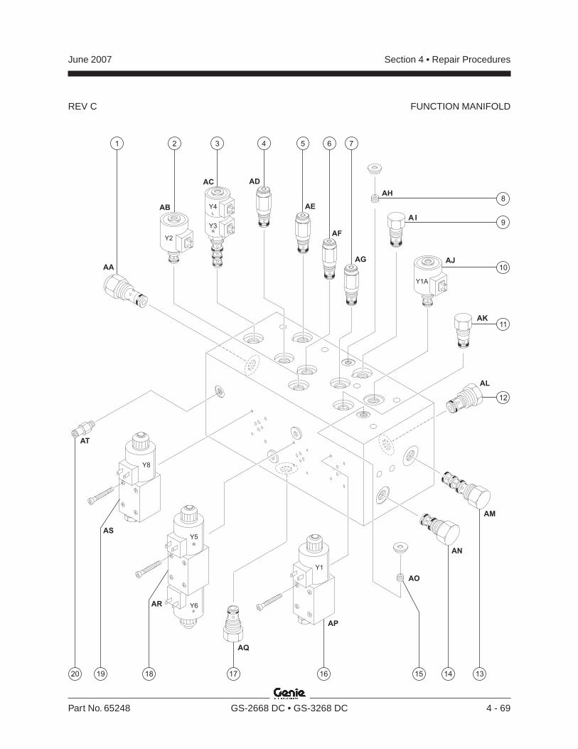
REV C
Section 4 • Repair ProceduresJune 2007
Part No. 65248 GS-2668 DC • GS-3268 DC 4 - 69
FUNCTION MANIFOLD
AA
AB
Y2
Y1
Y8
Y5
Y6
Y1A
Y4L
R
R
F
Y3
AC AD
AE
AF
AG
AH
A I
AJ
AK
AL
AM
AN
AO
AP
AQ
AR
AS
AT
1920 13141517 16
2 3 4 7651
9
8
10
12
11
18
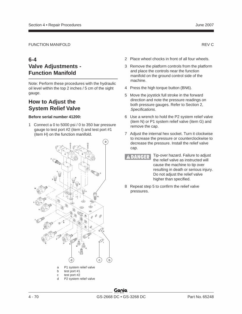
REV C
Section 4 • Repair Procedures June 2007
4 - 70 GS-2668 DC • GS-3268 DC Part No. 65248
6-4Valve Adjustments -Function Manifold
Note: Perform these procedures with the hydraulicoil level within the top 2 inches / 5 cm of the sightgauge.
How to Adjust theSystem Relief ValveBefore serial number 41200:
1 Connect a 0 to 5000 psi / 0 to 350 bar pressuregauge to test port #2 (item I) and test port #1(item H) on the function manifold.
2 Place wheel chocks in front of all four wheels.
3 Remove the platform controls from the platformand place the controls near the functionmanifold on the ground control side of themachine.
4 Press the high torque button (BN6).
5 Move the joystick full stroke in the forwarddirection and note the pressure readings onboth pressure gauges. Refer to Section 2,Specifications.
6 Use a wrench to hold the P2 system relief valve(item N) or P1 system relief valve (item G) andremove the cap.
7 Adjust the internal hex socket. Turn it clockwiseto increase the pressure or counterclockwise todecrease the pressure. Install the relief valvecap.
Tip-over hazard. Failure to adjustthe relief valve as instructed willcause the machine to tip overresulting in death or serious injury.Do not adjust the relief valvehigher than specified.
8 Repeat step 5 to confirm the relief valvepressures.
a P1 system relief valveb test port #1c test port #2d P2 system relief valve
bcd
a
BA
C
D
E
G
F
H
I
J
K
L
M
O
P
R
Q
S
T
U
W
X
Y
Z
Y6
Y8Y4
Y1A
Y1B
Y1
Y3
Y5
Y5A
Y6A
Y2
V
N
FUNCTION MANIFOLD
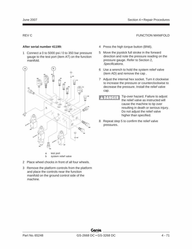
REV C
Section 4 • Repair ProceduresJune 2007
Part No. 65248 GS-2668 DC • GS-3268 DC 4 - 71
After serial number 41199:
1 Connect a 0 to 5000 psi / 0 to 350 bar pressuregauge to the test port (item AT) on the functionmanifold.
4 Press the high torque button (BN6).
5 Move the joystick full stroke in the forwarddirection and note the pressure reading on thepressure gauge. Refer to Section 2,Specifications.
6 Use a wrench to hold the system relief valve(item AD) and remove the cap .
7 Adjust the internal hex socket. Turn it clockwiseto increase the pressure or counterclockwise todecrease the pressure. Install the relief valvecap.
Tip-over hazard. Failure to adjustthe relief valve as instructed willcause the machine to tip overresulting in death or serious injury.Do not adjust the relief valvehigher than specified.
8 Repeat step 5 to confirm the relief valvepressures.
a test portb system relief valve
2 Place wheel chocks in front of all four wheels.
3 Remove the platform controls from the platformand place the controls near the functionmanifold on the ground control side of themachine.
AA
AB
Y2
Y1
Y8
Y5
Y6
Y1A
Y4L
R
R
F
Y3
AC AD
AE
AF
AG
AH
A I
AJ
AK
AL
AM
AN
AO
AP
AQ
AR
AS
AT
a b
FUNCTION MANIFOLD
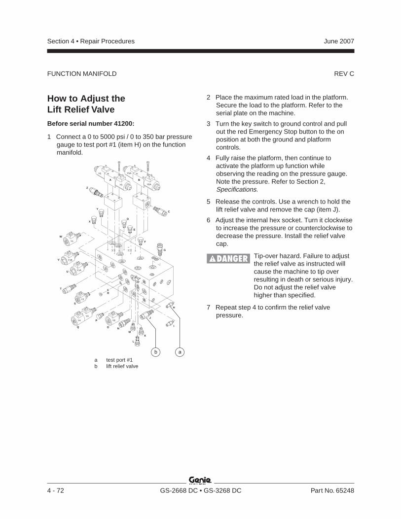
REV C
Section 4 • Repair Procedures June 2007
4 - 72 GS-2668 DC • GS-3268 DC Part No. 65248
How to Adjust theLift Relief ValveBefore serial number 41200:
1 Connect a 0 to 5000 psi / 0 to 350 bar pressuregauge to test port #1 (item H) on the functionmanifold.
2 Place the maximum rated load in the platform.Secure the load to the platform. Refer to theserial plate on the machine.
3 Turn the key switch to ground control and pullout the red Emergency Stop button to the onposition at both the ground and platformcontrols.
4 Fully raise the platform, then continue toactivate the platform up function whileobserving the reading on the pressure gauge.Note the pressure. Refer to Section 2,Specifications.
5 Release the controls. Use a wrench to hold thelift relief valve and remove the cap (item J).
6 Adjust the internal hex socket. Turn it clockwiseto increase the pressure or counterclockwise todecrease the pressure. Install the relief valvecap.
Tip-over hazard. Failure to adjustthe relief valve as instructed willcause the machine to tip overresulting in death or serious injury.Do not adjust the relief valvehigher than specified.
7 Repeat step 4 to confirm the relief valvepressure.
a test port #1b lift relief valve
a
BA
C
D
E
G
F
H
I
J
K
L
M
O
P
R
Q
S
T
U
W
X
Y
Z
Y6
Y8Y4
Y1A
Y1B
Y1
Y3
Y5
Y5A
Y6A
Y2
V
N
b
FUNCTION MANIFOLD
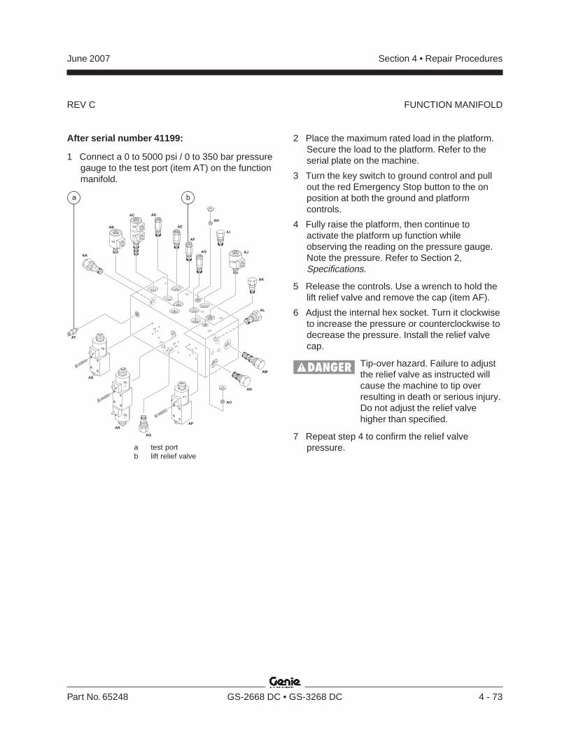
REV C
Section 4 • Repair ProceduresJune 2007
Part No. 65248 GS-2668 DC • GS-3268 DC 4 - 73
After serial number 41199:
1 Connect a 0 to 5000 psi / 0 to 350 bar pressuregauge to the test port (item AT) on the functionmanifold.
a test portb lift relief valve
2 Place the maximum rated load in the platform.Secure the load to the platform. Refer to theserial plate on the machine.
3 Turn the key switch to ground control and pullout the red Emergency Stop button to the onposition at both the ground and platformcontrols.
4 Fully raise the platform, then continue toactivate the platform up function whileobserving the reading on the pressure gauge.Note the pressure. Refer to Section 2,Specifications.
5 Release the controls. Use a wrench to hold thelift relief valve and remove the cap (item AF).
6 Adjust the internal hex socket. Turn it clockwiseto increase the pressure or counterclockwise todecrease the pressure. Install the relief valvecap.
Tip-over hazard. Failure to adjustthe relief valve as instructed willcause the machine to tip overresulting in death or serious injury.Do not adjust the relief valvehigher than specified.
7 Repeat step 4 to confirm the relief valvepressure.
AA
AB
Y2
Y1
Y8
Y5
Y6
Y1A
Y4L
R
R
F
Y3
AC AD
AE
AF
AG
AH
A I
AJ
AK
AL
AM
AN
AO
AP
AQ
AR
AS
AT
a b
FUNCTION MANIFOLD
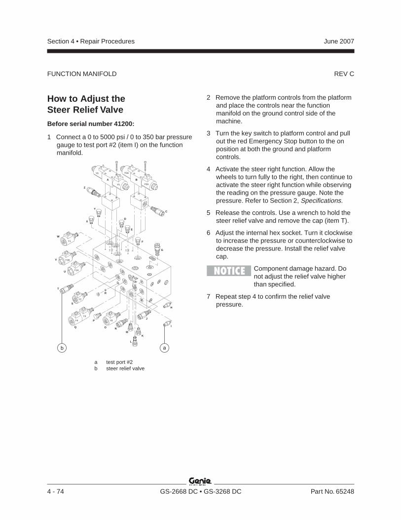
REV C
Section 4 • Repair Procedures June 2007
4 - 74 GS-2668 DC • GS-3268 DC Part No. 65248
How to Adjust theSteer Relief ValveBefore serial number 41200:
1 Connect a 0 to 5000 psi / 0 to 350 bar pressuregauge to test port #2 (item I) on the functionmanifold.
a test port #2b steer relief valve
2 Remove the platform controls from the platformand place the controls near the functionmanifold on the ground control side of themachine.
3 Turn the key switch to platform control and pullout the red Emergency Stop button to the onposition at both the ground and platformcontrols.
4 Activate the steer right function. Allow thewheels to turn fully to the right, then continue toactivate the steer right function while observingthe reading on the pressure gauge. Note thepressure. Refer to Section 2, Specifications.
5 Release the controls. Use a wrench to hold thesteer relief valve and remove the cap (item T).
6 Adjust the internal hex socket. Turn it clockwiseto increase the pressure or counterclockwise todecrease the pressure. Install the relief valvecap.
Component damage hazard. Donot adjust the relief valve higherthan specified.
7 Repeat step 4 to confirm the relief valvepressure.
a
BA
C
D
E
G
F
H
I
J
K
L
M
O
P
R
Q
S
T
U
W
X
Y
Z
Y6
Y8Y4
Y1A
Y1B
Y1
Y3
Y5
Y5A
Y6A
Y2
V
N
b
FUNCTION MANIFOLD
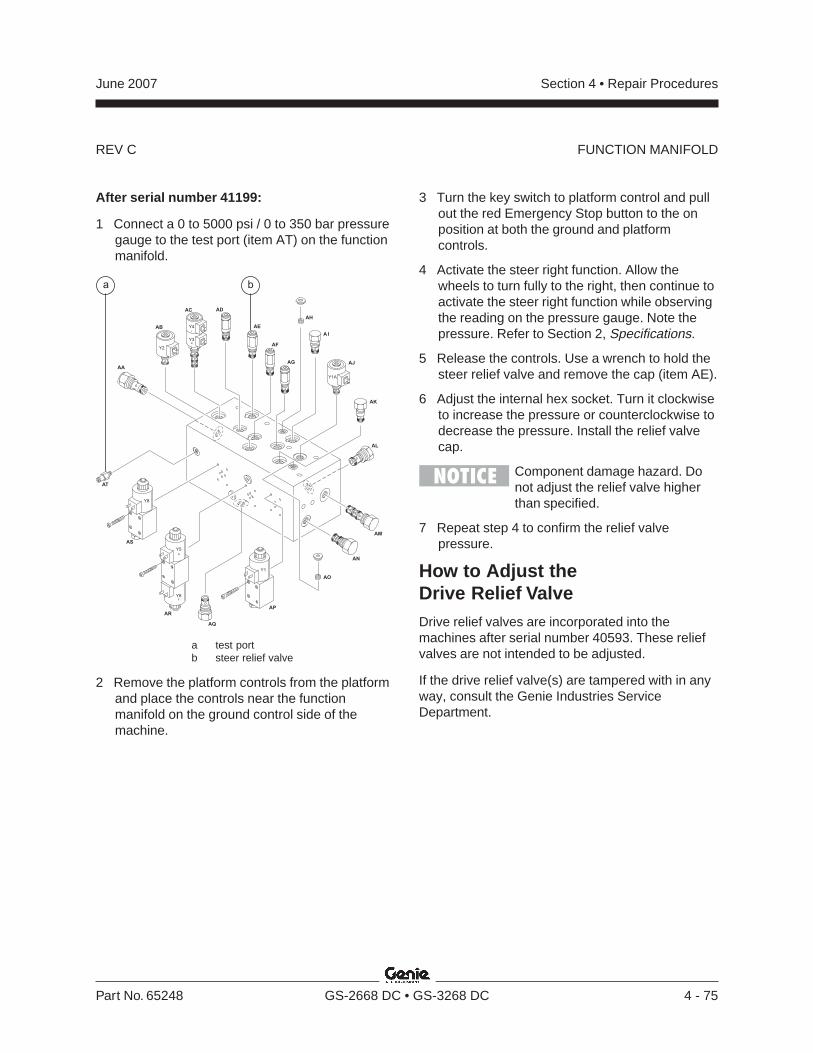
REV C
Section 4 • Repair ProceduresJune 2007
Part No. 65248 GS-2668 DC • GS-3268 DC 4 - 75
After serial number 41199:
1 Connect a 0 to 5000 psi / 0 to 350 bar pressuregauge to the test port (item AT) on the functionmanifold.
a test portb steer relief valve
2 Remove the platform controls from the platformand place the controls near the functionmanifold on the ground control side of themachine.
3 Turn the key switch to platform control and pullout the red Emergency Stop button to the onposition at both the ground and platformcontrols.
4 Activate the steer right function. Allow thewheels to turn fully to the right, then continue toactivate the steer right function while observingthe reading on the pressure gauge. Note thepressure. Refer to Section 2, Specifications.
5 Release the controls. Use a wrench to hold thesteer relief valve and remove the cap (item AE).
6 Adjust the internal hex socket. Turn it clockwiseto increase the pressure or counterclockwise todecrease the pressure. Install the relief valvecap.
Component damage hazard. Donot adjust the relief valve higherthan specified.
7 Repeat step 4 to confirm the relief valvepressure.
How to Adjust theDrive Relief ValveDrive relief valves are incorporated into themachines after serial number 40593. These reliefvalves are not intended to be adjusted.
If the drive relief valve(s) are tampered with in anyway, consult the Genie Industries ServiceDepartment.
AA
AB
Y2
Y1
Y8
Y5
Y6
Y1A
Y4L
R
R
F
Y3
AC AD
AE
AF
AG
AH
A I
AJ
AK
AL
AM
AN
AO
AP
AQ
AR
AS
AT
a b
FUNCTION MANIFOLD

REV C
Section 4 • Repair Procedures June 2007
4 - 76 GS-2668 DC • GS-3268 DC Part No. 65248
Valve Coil ResistanceSpecificationsNote: The following coil resistance specificationsare at an ambient temperature of 68°F / 20°C. Asvalve coil resistance is sensitive to changes in airtemperature, the coil resistance will typicallyincrease or decrease by 4% for each 18°F / 20°Cthat your air temperature increases or decreasesfrom 68°F / 20°C.
DescriptionSpecification
DO3 valve, 3 position 4 way 7Ω12V DC (schematic items A and B)
Solenoid valve, 2 position 2 way 7Ω10V DC (schematic item S)
Solenoid valve, 2 position 2 way 5Ω10V DC (schematic items U, V and W)
Solenoid valve, 2 position 4 way 5Ω10V DC (schematic item O)
Solenoid valve, 3 position 4 way 5Ω10V DC (schematic item Q)
Solenoid valve, 2 position 2 way 34Ω24V DC (schematic item AB)
Solenoid valve, 3 position 4 way 34Ω24V DC (schematic item AC)
Solenoid valve, 2 position 2 way 29Ω24V DC (schematic item AJ)
DO3 valve, 2 position 4 way 22Ω24V DC (schematic items AP and AS)
DO3 valve, 3 position 4 way 22Ω24V DC (schematic item AR)
Solenoid valve, 2 position 2 way 12Ω20V DC (schematic item BA)
6-5Valve Coils
How to Test a Valve CoilA properly functioning valve coil provides anelectromotive force which operates the solenoidvalve. Critical to normal operation is continuitywithin the coil that provides this force field.
Electrocution hazard. Contact withelectrically charged circuits couldresult in death or serious injury.Remove all rings, watches andother jewelry.
1 Tag and disconnect the wire harness from thecoil to be tested.
2 Test the coil resistance.
Result: The resistance should be withinspecification, plus or minus 30%.
Result: If the resistance is not withinspecification, plus or minus 30%, replace thecoil.
FUNCTION MANIFOLD
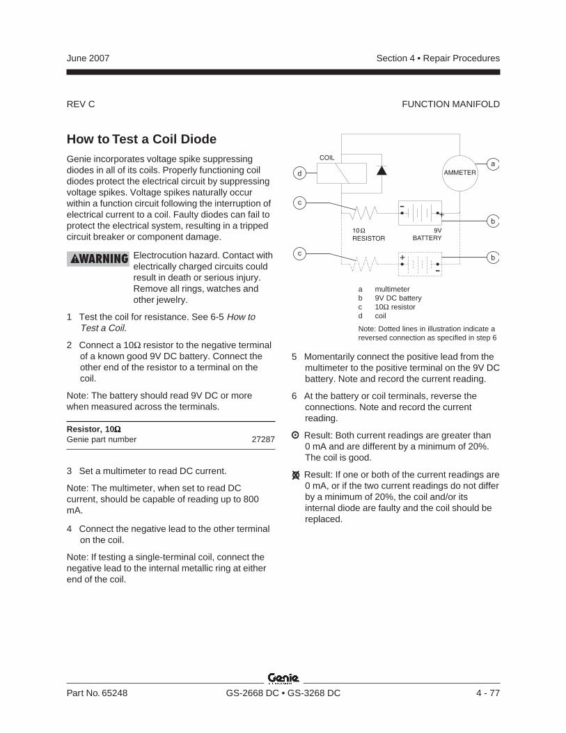
REV C
Section 4 • Repair ProceduresJune 2007
Part No. 65248 GS-2668 DC • GS-3268 DC 4 - 77
9VBATTERY
10
RESISTOR
AMMETER
COIL
+
-
+
-
d
b
b
a
c
c
How to Test a Coil DiodeGenie incorporates voltage spike suppressingdiodes in all of its coils. Properly functioning coildiodes protect the electrical circuit by suppressingvoltage spikes. Voltage spikes naturally occurwithin a function circuit following the interruption ofelectrical current to a coil. Faulty diodes can fail toprotect the electrical system, resulting in a trippedcircuit breaker or component damage.
Electrocution hazard. Contact withelectrically charged circuits couldresult in death or serious injury.Remove all rings, watches andother jewelry.
1 Test the coil for resistance. See 6-5 How toTest a Coil.
2 Connect a 10Ω resistor to the negative terminalof a known good 9V DC battery. Connect theother end of the resistor to a terminal on thecoil.
Note: The battery should read 9V DC or morewhen measured across the terminals.
Resistor, 10ΩΩΩΩΩGenie part number 27287
3 Set a multimeter to read DC current.
Note: The multimeter, when set to read DCcurrent, should be capable of reading up to 800mA.
4 Connect the negative lead to the other terminalon the coil.
Note: If testing a single-terminal coil, connect thenegative lead to the internal metallic ring at eitherend of the coil.
FUNCTION MANIFOLD
a multimeterb 9V DC batteryc 10Ω resistord coil
Note: Dotted lines in illustration indicate areversed connection as specified in step 6
5 Momentarily connect the positive lead from themultimeter to the positive terminal on the 9V DCbattery. Note and record the current reading.
6 At the battery or coil terminals, reverse theconnections. Note and record the currentreading.
Result: Both current readings are greater than0 mA and are different by a minimum of 20%.The coil is good.
Result: If one or both of the current readings are0 mA, or if the two current readings do not differby a minimum of 20%, the coil and/or itsinternal diode are faulty and the coil should bereplaced.
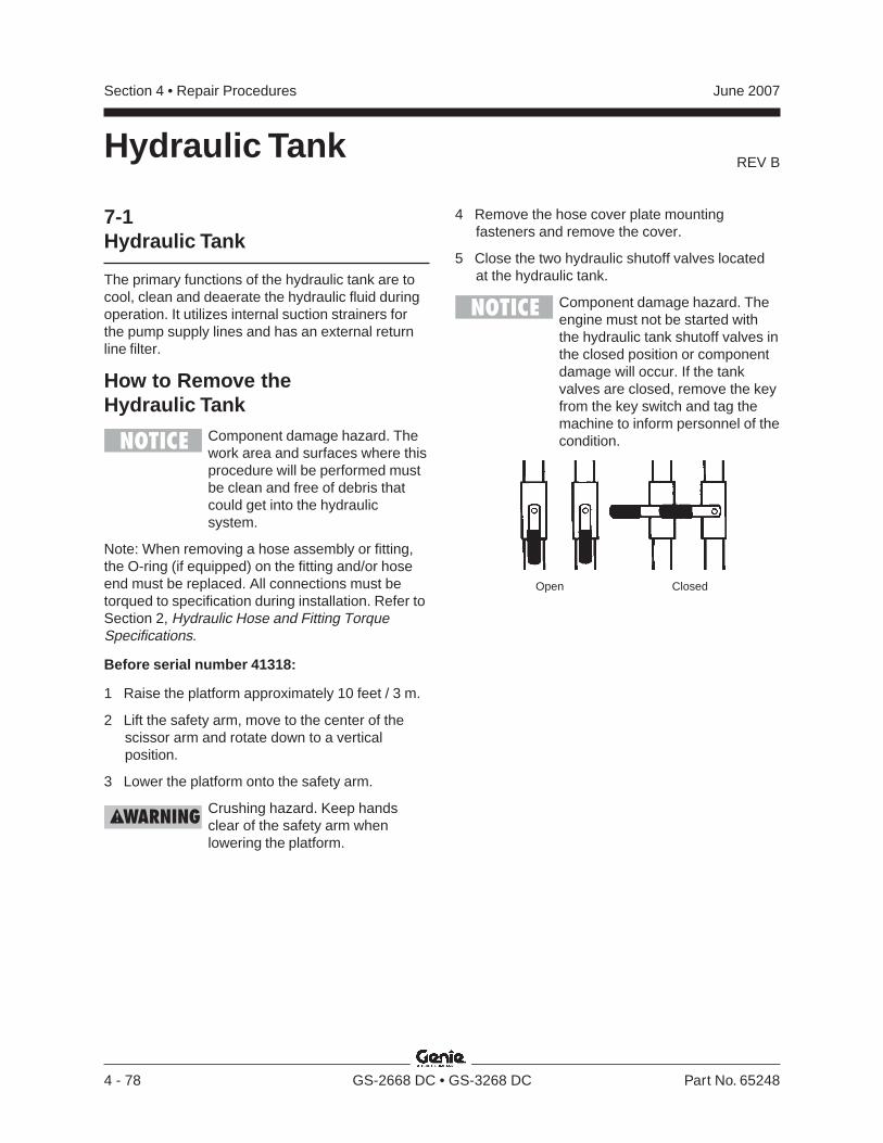
REV B
Section 4 • Repair Procedures June 2007
4 - 78 GS-2668 DC • GS-3268 DC Part No. 65248
7-1Hydraulic Tank
The primary functions of the hydraulic tank are tocool, clean and deaerate the hydraulic fluid duringoperation. It utilizes internal suction strainers forthe pump supply lines and has an external returnline filter.
How to Remove theHydraulic Tank
Component damage hazard. Thework area and surfaces where thisprocedure will be performed mustbe clean and free of debris thatcould get into the hydraulicsystem.
Note: When removing a hose assembly or fitting,the O-ring (if equipped) on the fitting and/or hoseend must be replaced. All connections must betorqued to specification during installation. Refer toSection 2, Hydraulic Hose and Fitting TorqueSpecifications.
Before serial number 41318:
1 Raise the platform approximately 10 feet / 3 m.
2 Lift the safety arm, move to the center of thescissor arm and rotate down to a verticalposition.
3 Lower the platform onto the safety arm.
Crushing hazard. Keep handsclear of the safety arm whenlowering the platform.
4 Remove the hose cover plate mountingfasteners and remove the cover.
5 Close the two hydraulic shutoff valves locatedat the hydraulic tank.
Component damage hazard. Theengine must not be started withthe hydraulic tank shutoff valves inthe closed position or componentdamage will occur. If the tankvalves are closed, remove the keyfrom the key switch and tag themachine to inform personnel of thecondition.
Hydraulic Tank
Open Closed
REV B
Section 4 • Repair ProceduresJune 2007
Part No. 65248 GS-2668 DC • GS-3268 DC 4 - 79
HYDRAULIC TANK
All models:
6 Disconnect the battery pack from the machine.
Electrocution hazard. Contact withelectrically charged circuits couldresult in death or serious injury.Remove all rings, watches andother jewelry.
7 Remove the drain plug from the hydraulic tankand allow all of the oil from the tank to drain intoa suitable container. Refer to Section 2,Specifications.
Bodily injury hazard. Sprayinghydraulic oil can penetrate andburn skin. Loosen hydraulicconnections very slowly to allowthe oil pressure to dissipategradually. Do not allow oil to squirtor spray.
8 Tag and disconnect and plug the two suctionhoses from the hydraulic tank.
9 Tag, disconnect and plug the hydraulic hose atthe return filter. Cap the fitting on the filter.
10 Remove the tank strap fasteners and removethe tank strap.
11 Remove the hydraulic tank from the machine.
After serial number 41317:
1 Disconnect the battery pack from the machine.
Electrocution hazard. Contact withelectrically charged circuits couldresult in death or serious injury.Remove all rings, watches andother jewelry.
2 Open the door to access the hydraulic tank.
3 Remove the drain plug from the hydraulic tankand allow all of the oil from the tank to drain intoa suitable container. Refer to Section 2,Specifications.
Bodily injury hazard. Sprayinghydraulic oil can penetrate andburn skin. Loosen hydraulicconnections very slowly to allowthe oil pressure to dissipategradually. Do not allow oil to squirtor spray.
4 Tag, disconnect and plug the hydraulic hose atthe return filter. Cap the fitting on the filter.
5 Tag, disconnect and plug the hydraulic pumpinlet hose at the pump. Cap the fitting on thepump.
6 Remove the hydraulic tank retaining fastenersand remove the hydraulic tank from themachine.
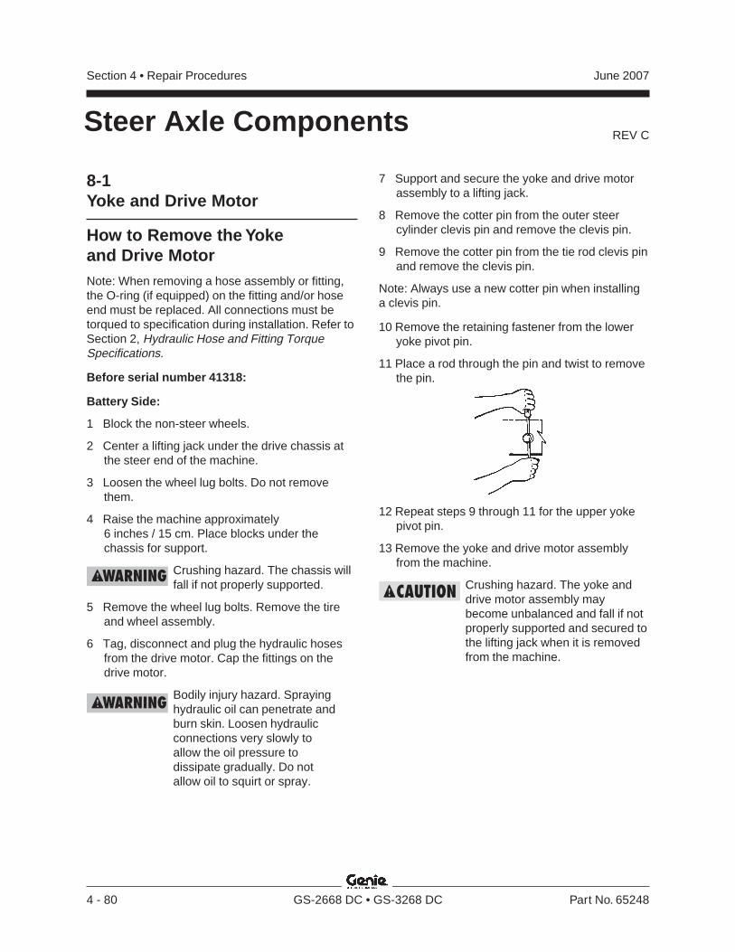
REV C
Section 4 • Repair Procedures June 2007
4 - 80 GS-2668 DC • GS-3268 DC Part No. 65248
Steer Axle Components
8-1Yoke and Drive Motor
How to Remove the Yokeand Drive MotorNote: When removing a hose assembly or fitting,the O-ring (if equipped) on the fitting and/or hoseend must be replaced. All connections must betorqued to specification during installation. Refer toSection 2, Hydraulic Hose and Fitting TorqueSpecifications.
Before serial number 41318:
Battery Side:
1 Block the non-steer wheels.
2 Center a lifting jack under the drive chassis atthe steer end of the machine.
3 Loosen the wheel lug bolts. Do not removethem.
4 Raise the machine approximately6 inches / 15 cm. Place blocks under thechassis for support.
Crushing hazard. The chassis willfall if not properly supported.
5 Remove the wheel lug bolts. Remove the tireand wheel assembly.
6 Tag, disconnect and plug the hydraulic hosesfrom the drive motor. Cap the fittings on thedrive motor.
Bodily injury hazard. Sprayinghydraulic oil can penetrate andburn skin. Loosen hydraulicconnections very slowly toallow the oil pressure todissipate gradually. Do notallow oil to squirt or spray.
7 Support and secure the yoke and drive motorassembly to a lifting jack.
8 Remove the cotter pin from the outer steercylinder clevis pin and remove the clevis pin.
9 Remove the cotter pin from the tie rod clevis pinand remove the clevis pin.
Note: Always use a new cotter pin when installinga clevis pin.
10 Remove the retaining fastener from the loweryoke pivot pin.
11 Place a rod through the pin and twist to removethe pin.
12 Repeat steps 9 through 11 for the upper yokepivot pin.
13 Remove the yoke and drive motor assemblyfrom the machine.
Crushing hazard. The yoke anddrive motor assembly maybecome unbalanced and fall if notproperly supported and secured tothe lifting jack when it is removedfrom the machine.
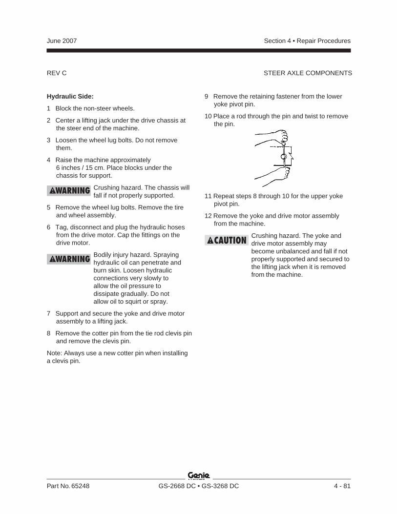
REV C
Section 4 • Repair ProceduresJune 2007
Part No. 65248 GS-2668 DC • GS-3268 DC 4 - 81
STEER AXLE COMPONENTS
Hydraulic Side:
1 Block the non-steer wheels.
2 Center a lifting jack under the drive chassis atthe steer end of the machine.
3 Loosen the wheel lug bolts. Do not removethem.
4 Raise the machine approximately6 inches / 15 cm. Place blocks under thechassis for support.
Crushing hazard. The chassis willfall if not properly supported.
5 Remove the wheel lug bolts. Remove the tireand wheel assembly.
6 Tag, disconnect and plug the hydraulic hosesfrom the drive motor. Cap the fittings on thedrive motor.
Bodily injury hazard. Sprayinghydraulic oil can penetrate andburn skin. Loosen hydraulicconnections very slowly toallow the oil pressure todissipate gradually. Do notallow oil to squirt or spray.
7 Support and secure the yoke and drive motorassembly to a lifting jack.
8 Remove the cotter pin from the tie rod clevis pinand remove the clevis pin.
Note: Always use a new cotter pin when installinga clevis pin.
9 Remove the retaining fastener from the loweryoke pivot pin.
10 Place a rod through the pin and twist to removethe pin.
11 Repeat steps 8 through 10 for the upper yokepivot pin.
12 Remove the yoke and drive motor assemblyfrom the machine.
Crushing hazard. The yoke anddrive motor assembly maybecome unbalanced and fall if notproperly supported and secured tothe lifting jack when it is removedfrom the machine.
REV C
Section 4 • Repair Procedures June 2007
4 - 82 GS-2668 DC • GS-3268 DC Part No. 65248
How to Remove a Drive MotorNote: When removing a hose assembly or fitting,the O-ring (if equipped) on the fitting and/or hoseend must be replaced. All connections must betorqued to specification during installation. Refer toSection 2, Hydraulic Hose and Fitting TorqueSpecifications.
Before serial number 41318:
1 Block the non-steer wheels and center a liftingjack under the drive chassis at the steer end.
2 Loosen the wheel lug bolts. Do not removethem.
3 Raise the machine approximately2 inches / 5 cm. Place blocks under the chassisfor support.
Crushing hazard. The chassis willfall if it is not properly supported.
4 Remove the wheel lug bolts. Remove the tireand wheel assembly.
5 Tag, disconnect and plug the hydraulic hosesfrom the drive motor. Cap the fittings on thedrive motor.
Bodily injury hazard. Sprayinghydraulic oil can penetrate andburn skin. Loosen hydraulicconnections very slowly toallow the oil pressure todissipate gradually. Do notallow oil to squirt or spray.
Component damage hazard.Hoses can be damaged if they arekinked or pinched.
6 Remove the drive motor mounting fastenersand remove the drive motor.
STEER AXLE COMPONENTS
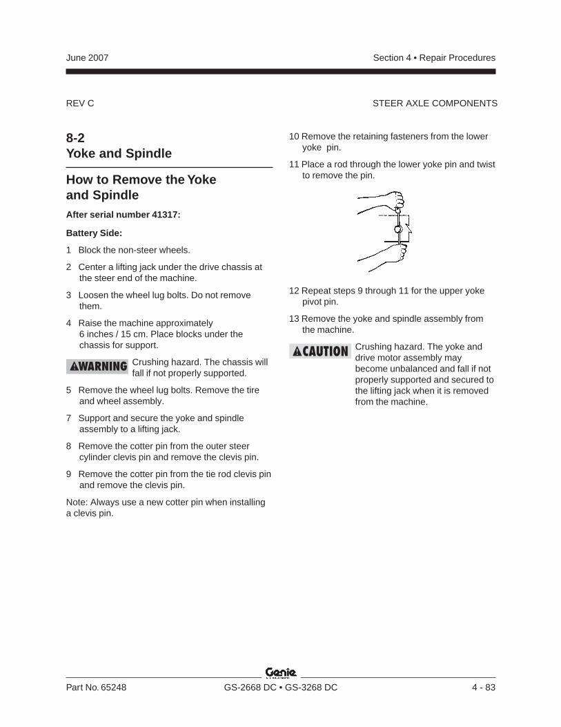
REV C
Section 4 • Repair ProceduresJune 2007
Part No. 65248 GS-2668 DC • GS-3268 DC 4 - 83
10 Remove the retaining fasteners from the loweryoke pin.
11 Place a rod through the lower yoke pin and twistto remove the pin.
STEER AXLE COMPONENTS
8-2Yoke and Spindle
How to Remove the Yokeand SpindleAfter serial number 41317:
Battery Side:
1 Block the non-steer wheels.
2 Center a lifting jack under the drive chassis atthe steer end of the machine.
3 Loosen the wheel lug bolts. Do not removethem.
4 Raise the machine approximately6 inches / 15 cm. Place blocks under thechassis for support.
Crushing hazard. The chassis willfall if not properly supported.
5 Remove the wheel lug bolts. Remove the tireand wheel assembly.
7 Support and secure the yoke and spindleassembly to a lifting jack.
8 Remove the cotter pin from the outer steercylinder clevis pin and remove the clevis pin.
9 Remove the cotter pin from the tie rod clevis pinand remove the clevis pin.
Note: Always use a new cotter pin when installinga clevis pin.
12 Repeat steps 9 through 11 for the upper yokepivot pin.
13 Remove the yoke and spindle assembly fromthe machine.
Crushing hazard. The yoke anddrive motor assembly maybecome unbalanced and fall if notproperly supported and secured tothe lifting jack when it is removedfrom the machine.
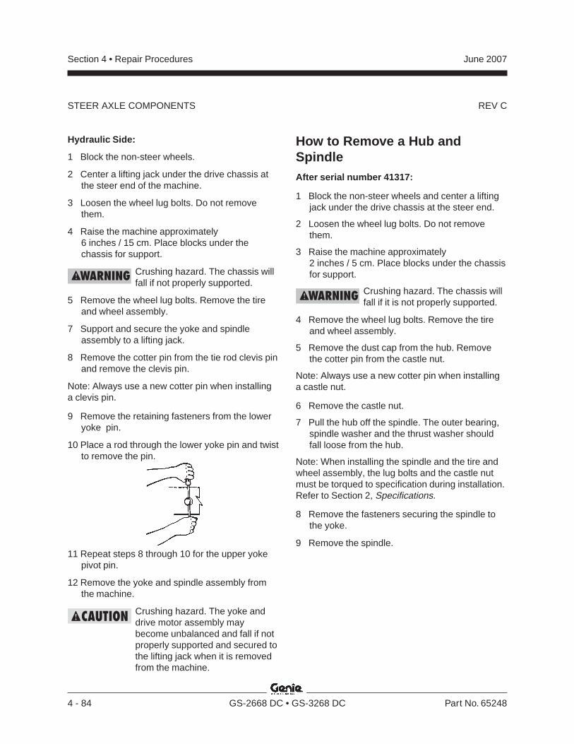
REV C
Section 4 • Repair Procedures June 2007
4 - 84 GS-2668 DC • GS-3268 DC Part No. 65248
Hydraulic Side:
1 Block the non-steer wheels.
2 Center a lifting jack under the drive chassis atthe steer end of the machine.
3 Loosen the wheel lug bolts. Do not removethem.
4 Raise the machine approximately6 inches / 15 cm. Place blocks under thechassis for support.
Crushing hazard. The chassis willfall if not properly supported.
5 Remove the wheel lug bolts. Remove the tireand wheel assembly.
7 Support and secure the yoke and spindleassembly to a lifting jack.
8 Remove the cotter pin from the tie rod clevis pinand remove the clevis pin.
Note: Always use a new cotter pin when installinga clevis pin.
9 Remove the retaining fasteners from the loweryoke pin.
10 Place a rod through the lower yoke pin and twistto remove the pin.
11 Repeat steps 8 through 10 for the upper yokepivot pin.
12 Remove the yoke and spindle assembly fromthe machine.
Crushing hazard. The yoke anddrive motor assembly maybecome unbalanced and fall if notproperly supported and secured tothe lifting jack when it is removedfrom the machine.
How to Remove a Hub andSpindleAfter serial number 41317:
1 Block the non-steer wheels and center a liftingjack under the drive chassis at the steer end.
2 Loosen the wheel lug bolts. Do not removethem.
3 Raise the machine approximately2 inches / 5 cm. Place blocks under the chassisfor support.
Crushing hazard. The chassis willfall if it is not properly supported.
4 Remove the wheel lug bolts. Remove the tireand wheel assembly.
5 Remove the dust cap from the hub. Removethe cotter pin from the castle nut.
Note: Always use a new cotter pin when installinga castle nut.
6 Remove the castle nut.
7 Pull the hub off the spindle. The outer bearing,spindle washer and the thrust washer shouldfall loose from the hub.
Note: When installing the spindle and the tire andwheel assembly, the lug bolts and the castle nutmust be torqued to specification during installation.Refer to Section 2, Specifications.
8 Remove the fasteners securing the spindle tothe yoke.
9 Remove the spindle.
STEER AXLE COMPONENTS
REV C
Section 4 • Repair ProceduresJune 2007
Part No. 65248 GS-2668 DC • GS-3268 DC 4 - 85
8-3Steer Cylinder
How to Remove theSteer CylinderNote: When removing a hose assembly or fitting,the O-ring (if equipped) on the fitting and/or hoseend must be replaced. All connections must betorqued to specification during installation. Refer toSection 2, Hydraulic Hose and Fitting TorqueSpecifications.
1 Block the non-steer wheels.
2 Tag, disconnect and plug the hydraulic hosesfrom the steering cylinder. Cap the fittings onthe cylinder.
Bodily injury hazard. Sprayinghydraulic oil can penetrate andburn skin. Loosen hydraulicconnections very slowly toallow the oil pressure todissipate gradually. Do notallow oil to squirt or spray.
Component damage hazard.Hoses can be damaged if they arekinked or pinched.
STEER AXLE COMPONENTS
3 Remove the pin retaining fasteners from thebarrel-end pivot pin. Use a soft metal drift toremove the pivot pin.
Note: Note the quantity and location of the spacerswhen removing the rod-end pivot pin.
4 Remove the pin retaining fasteners from therod-end pivot pin. Use a soft metal drift toremove the pin.
Note: Note the quantity and location of the spacerswhen removing the rod-end pivot pin.
5 Remove the steer cylinder from the machine.
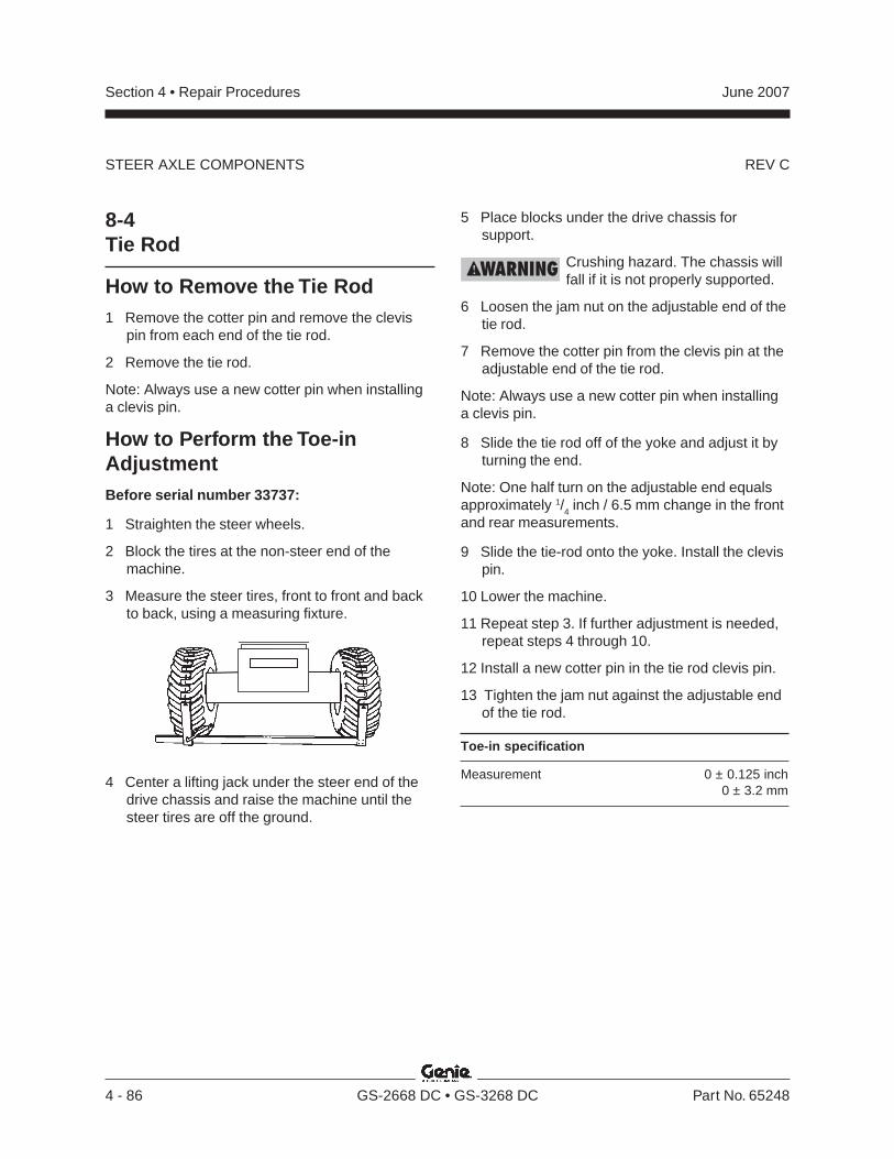
REV C
Section 4 • Repair Procedures June 2007
4 - 86 GS-2668 DC • GS-3268 DC Part No. 65248
STEER AXLE COMPONENTS
8-4Tie Rod
How to Remove the Tie Rod1 Remove the cotter pin and remove the clevis
pin from each end of the tie rod.
2 Remove the tie rod.
Note: Always use a new cotter pin when installinga clevis pin.
How to Perform the Toe-inAdjustmentBefore serial number 33737:
1 Straighten the steer wheels.
2 Block the tires at the non-steer end of themachine.
3 Measure the steer tires, front to front and backto back, using a measuring fixture.
5 Place blocks under the drive chassis forsupport.
Crushing hazard. The chassis willfall if it is not properly supported.
6 Loosen the jam nut on the adjustable end of thetie rod.
7 Remove the cotter pin from the clevis pin at theadjustable end of the tie rod.
Note: Always use a new cotter pin when installinga clevis pin.
8 Slide the tie rod off of the yoke and adjust it byturning the end.
Note: One half turn on the adjustable end equalsapproximately 1/
4 inch / 6.5 mm change in the front
and rear measurements.
9 Slide the tie-rod onto the yoke. Install the clevispin.
10 Lower the machine.
11 Repeat step 3. If further adjustment is needed,repeat steps 4 through 10.
12 Install a new cotter pin in the tie rod clevis pin.
13 Tighten the jam nut against the adjustable endof the tie rod.
Toe-in specification
Measurement 0 ± 0.125 inch0 ± 3.2 mm
4 Center a lifting jack under the steer end of thedrive chassis and raise the machine until thesteer tires are off the ground.
REV C
Section 4 • Repair ProceduresJune 2007
Part No. 65248 GS-2668 DC • GS-3268 DC 4 - 87
Non-steer Axle Components
9-1Brake Motor
How to Remove a Brake MotorNote: When removing a hose assembly or fitting,the O-ring (if equipped) on the fitting and/or hoseend must be replaced. All connections must betorqued to specification during installation. Refer toSection 2, Hydraulic Hose and Fitting TorqueSpecifications.
Before serial number 41318:
1 Block the steer wheels.
2 Center a lifting jack under the drive chassis atthe non-steer end.
3 Loosen the wheel lug bolts. Do not removethem.
4 Raise the machine approximately2 inches / 5 cm. Place blocks under the chassisfor support.
Crushing hazard. The chassis willfall if not properly supported.
5 Remove the wheel lug bolts. Remove the tireand wheel assembly.
6 Tag, disconnect and plug the hydraulic hosesfrom the brake motor. Cap the fittings on thebrake motor.
Note: When removing a hose assembly or fitting,the O-ring (if equipped) on the fitting and/or hoseend must be replaced. All connections must betorqued to specification during installation. Refer toSection 2, Hydraulic Hose and Fitting TorqueSpecifications.
7 Support and secure the brake assembly to alifting jack.
8 Remove the brake mounting fasteners.
9 Remove the brake motor from the machine.
Crushing hazard. The drive motorand brake assembly may becomeunbalanced and fall when it isremoved from the machine if it isnot properly supported andsecured to the lifting jack.
REV C
Section 4 • Repair Procedures June 2007
4 - 88 GS-2668 DC • GS-3268 DC Part No. 65248
9-2Drive/Brake Motor
How to Remove a Drive/BrakeMotorNote: When removing a hose assembly or fitting,the O-ring (if equipped) on the fitting and/or hoseend must be replaced. All connections must betorqued to specification during installation. Refer toSection 2, Hydraulic Hose and Fitting TorqueSpecifications.
After serial number 41317:
1 Block the steer wheels.
2 Center a lifting jack under the drive chassis atthe non-steer end.
3 Loosen the wheel lug bolts. Do not removethem.
4 Raise the machine approximately2 inches / 5 cm. Place blocks under the chassisfor support.
Crushing hazard. The chassis willfall if not properly supported.
5 Remove the wheel lug bolts. Remove the tireand wheel assembly.
6 Tag, disconnect and plug the hydraulic hosesfrom the drive/brake motor. Cap the fittings onthe drive/brake motor.
Bodily injury hazard. Sprayinghydraulic oil can penetrate andburn skin. Loosen hydraulicconnections very slowly toallow the oil pressure todissipate gradually. Do notallow oil to squirt or spray.
7 Support and secure the drive motor/brakeassembly to a lifting jack.
8 Remove the drive/brake motor mountingfasteners.
9 Remove the drive/brake motor from themachine.
Crushing hazard. The drive motorand brake assembly may becomeunbalanced and fall when it isremoved from the machine if it isnot properly supported andsecured to the lifting jack.
NON-STEER AXLE COMPONENTS

REV C
Section 4 • Repair ProceduresJune 2007
Part No. 65248 GS-2668 DC • GS-3268 DC 4 - 89
Brake Release Hand Pump Components
10-1Brake Release Hand Pump Components
The brake release hand pump manifold is mounted behind the entry ladder next to the battery charger.
Index SchematicNo. Description Item Function Torque
1 Shuttle valve ..................................... BC ............ Brake release circuit ..................... 45-50 ft-lbs / 61-68 Nm
2 Check valve, pilot operated .............. BD ............ Manual brake release circuit ........ 65-70 ft-lbs / 88-95 Nm
3 Hand pump ....................................... BE ............. Manual brake release .............................. 30 ft-lbs / 41 Nm
4 Needle valve ..................................... BF ............. Manual brake release enable ....... 45-50 ft-lbs / 61-68 Nm
Before serial number GS6804-43184
After serial number 43183GS6804-
BC
BD
BE
BF
Note: 'alpha' callouts referto corresponding notes onthe hydraulic schematic
BE
BF
Section 4 • Repair Procedures June 2007
4 - 90 GS-2668 DC • GS-3268 DC Part No. 65248
This page intentionally left blank.
Section 5 • Troubleshooting Flow ChartsJune 2007
Part No. 65248 GS-2668 DC • GS-3268 DC 5 - 1
Before Troubleshooting:
Read, understand and obey the safety rulesand operating instructions printed in theappropriate Operator’s Manual.
Be sure that all necessary tools and testequipment are available and ready for use.
Read each appropriate flow chart thoroughly.Attempting shortcuts may produce hazardousconditions.
Be aware of the following hazards and followgenerally accepted safe workshop practices.
Crushing hazard. When testingor replacing any hydrauliccomponent, always supportthe structure and secure itfrom movement.
Electrocution hazard. Contactwith electrically charged circuitscould result in death or seriousinjury. Remove all rings, watchesand other jewelry.
Bodily injury hazard. Sprayinghydraulic oil can penetrate andburn skin. Loosen hydraulicconnections very slowly to allowthe oil pressure to dissipategradually. Do not allow oil tosquirt or spray.
Two persons will be required tosafely perform sometroubleshooting procedures.
Troubleshooting Flow Charts
Observe and Obey:
Troubleshooting and repair procedures shall becompleted by a person trained and qualified onthe repair of this machine.
Immediately tag and remove from service adamaged or malfunctioning machine.
Repair any machine damage or malfunctionbefore operating the machine.
Unless otherwise specified, perform eachrepair procedure with the machine in thefollowing configuration:
· Key switch in the off position with the keyremoved
· Machine parked on a firm, level surface
· Platform in stowed position
· Key switch in the off position with the keyremoved
· The red Emergency Stop button in the offposition at both ground and platform controls
· Wheels chocked
· All external AC power supply disconnectedfrom the machine
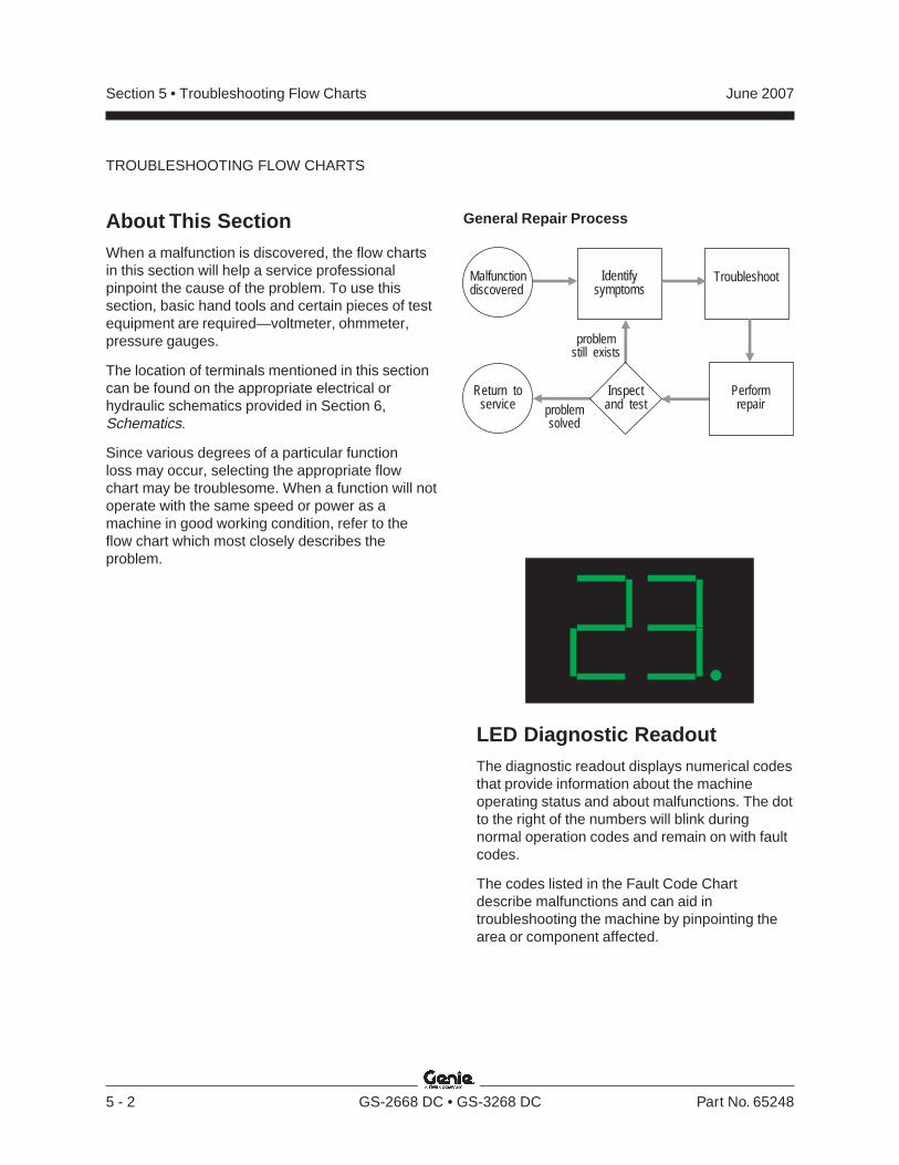
Section 5 • Troubleshooting Flow Charts June 2007
5 - 2 GS-2668 DC • GS-3268 DC Part No. 65248
General Repair ProcessAbout This SectionWhen a malfunction is discovered, the flow chartsin this section will help a service professionalpinpoint the cause of the problem. To use thissection, basic hand tools and certain pieces of testequipment are required—voltmeter, ohmmeter,pressure gauges.
The location of terminals mentioned in this sectioncan be found on the appropriate electrical orhydraulic schematics provided in Section 6,Schematics.
Since various degrees of a particular functionloss may occur, selecting the appropriate flowchart may be troublesome. When a function will notoperate with the same speed or power as amachine in good working condition, refer to theflow chart which most closely describes theproblem.
Malfunctiondiscovered
Identifysymptoms
Troubleshoot
Performrepair
Return toservice problem
solved
problemstill exists
Inspectand test
LED Diagnostic ReadoutThe diagnostic readout displays numerical codesthat provide information about the machineoperating status and about malfunctions. The dotto the right of the numbers will blink duringnormal operation codes and remain on with faultcodes.
The codes listed in the Fault Code Chartdescribe malfunctions and can aid introubleshooting the machine by pinpointing thearea or component affected.
TROUBLESHOOTING FLOW CHARTS
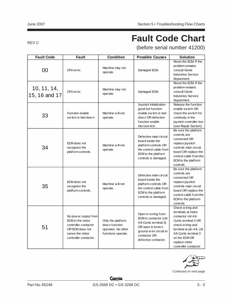
REV C
Section 5 • Troubleshooting Flow ChartsJune 2007
Part No. 65248 GS-2668 DC • GS-3268 DC 5 - 3
Fault Code Chart(before serial number 41200)
Continued on next page
Fault Code Fault Condition Possible Causes Solution
00 CPU error.Machine may not operate.
Damaged ECM.
Reset the ECM. If the problem remains consult Genie Industries Service Department.
10, 11, 14, 15, 16 and 17
CPU error.Machine may not operate.
Damaged ECM.
Reset the ECM. If the problem remains consult Genie Industries Service Department.
33Function enable sw itch is tied dow n.
Machine w ill not operate.
Joystick initialization good but function enable sw itch is tied dow n OR defective function enable microsw itch.
Release the function enable sw itch OR check the sw itch for continuity in the joystick controller box (see Repair Section).
34ECM does not recognize the platform controls.
Machine w ill not operate.
Defective main circuit board inside the platform controls OR the control cable from ECM to the platform controls is damaged.
Be sure the platform controls are connected OR replace joystick controls main circuit board OR replace the control cable from the ECM to the platform controls.
35ECM does not recognize the platform controls.
Machine w ill not operate.
Defective main circuit board inside the platform controls OR the control cable from ECM to the platform controls is damaged.
Be sure the platform controls are connected OR replace joystick controls main circuit board OR replace the control cable from the ECM to the platform controls.
51
No pow er output from ECM to the motor controller contactor OR ECM does not sense the motor controller contactor.
Only the platform dow n function operates. No other functions operate.
Open in w iring from ECM to contactor (ckt A9-Curtis terminal 3) OR open in brow n ground w ire circuit to contactor OR defective contactor.
Check w iring and terminals at motor contactor ckt A9-Curtis terminal 3 OR check w iring and terminal at pin A9, ckt A9-Curtis terminal 3 on the ECM OR replace motor controller contactor.
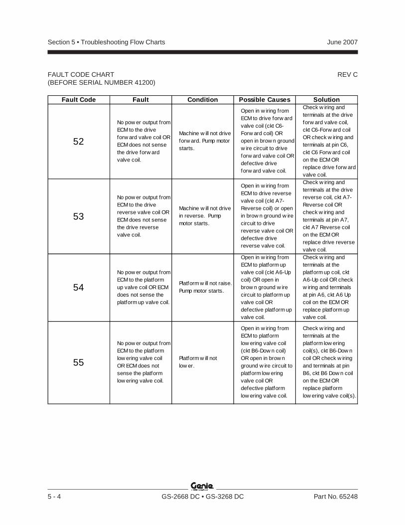
REV C
Section 5 • Troubleshooting Flow Charts June 2007
5 - 4 GS-2668 DC • GS-3268 DC Part No. 65248
FAULT CODE CHART(BEFORE SERIAL NUMBER 41200)
Fault Code Fault Condition Possible Causes Solution
52
No pow er output from ECM to the drive forw ard valve coil OR ECM does not sense the drive forw ard valve coil.
Machine w ill not drive forw ard. Pump motor starts.
Open in w iring from ECM to drive forw ard valve coil (ckt C6-Forw ard coil) OR open in brow n ground w ire circuit to drive forw ard valve coil OR defective drive forw ard valve coil.
Check w iring and terminals at the drive forw ard valve coil, ckt C6-Forw ard coil OR check w iring and terminals at pin C6, ckt C6 Forw ard coil on the ECM OR replace drive forw ard valve coil.
53
No pow er output from ECM to the drive reverse valve coil OR ECM does not sense the drive reverse valve coil.
Machine w ill not drive in reverse. Pump motor starts.
Open in w iring from ECM to drive reverse valve coil (ckt A7-Reverse coil) or open in brow n ground w ire circuit to drive reverse valve coil OR defective drive reverse valve coil.
Check w iring and terminals at the drive reverse coil, ckt A7-Reverse coil OR check w iring and terminals at pin A7, ckt A7 Reverse coil on the ECM OR replace drive reverse valve coil.
54
No pow er output from ECM to the platform up valve coil OR ECM does not sense the platform up valve coil.
Platform w ill not raise. Pump motor starts.
Open in w iring from ECM to platform up valve coil (ckt A6-Up coil) OR open in brow n ground w ire circuit to platform up valve coil OR defective platform up valve coil.
Check w iring and terminals at the platform up coil, ckt A6-Up coil OR check w iring and terminals at pin A6, ckt A6 Up coil on the ECM OR replace platform up valve coil.
55
No pow er output from ECM to the platform low ering valve coil OR ECM does not sense the platform low ering valve coil.
Platform w ill not low er.
Open in w iring from ECM to platform low ering valve coil (ckt B6-Dow n coil) OR open in brow n ground w ire circuit to platform low ering valve coil OR defective platform low ering valve coil.
Check w iring and terminals at the platform low ering coil(s), ckt B6-Dow n coil OR check w iring and terminals at pin B6, ckt B6 Dow n coil on the ECM OR replace platform low ering valve coil(s).
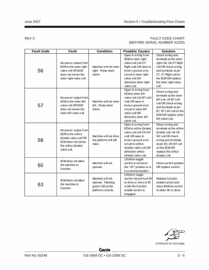
REV C
Section 5 • Troubleshooting Flow ChartsJune 2007
Part No. 65248 GS-2668 DC • GS-3268 DC 5 - 5
FAULT CODE CHART(BEFORE SERIAL NUMBER 41200)
Fault Code Fault Condition Possible Causes Solution
56
No pow er output from ECM to the steer right valve coil OR ECM does not sense the steer right valve coil.
Machine w ill not steer right. Pump motor starts.
Open in w iring from ECM to steer right valve coil (ckt C7-Right coil) OR open in brow n ground w ire circuit to steer right valve coil OR defective steer right valve coil.
Check w iring and terminals at the steer right coil, ckt C7 Right coil OR check w iring and terminals at pin C7, C7 Right coil on the ECM OR replace the steer right valve coil.
57
No pow er output from ECM to the steer left valve coil OR ECM does not sense the steer left valve coil.
Machine w ill not steer left. Pump motor starts.
Open in w iring from ECM to steer left valve coil (ckt B7-Left coil) OR open in brow n ground w ire circuit to steer left valve coil OR defective steer left valve coil.
Check w iring and terminals at the steer lef t coil, ckt B7 Left coil OR check w iring and terminals at pin B7, B7 Left coil on the ECM OR replace steer lef t valve coil.
58
No pow er output from ECM to the orif ice (brake) valve coil OR ECM does not sense the orif ice (brake) valve coil.
Machine w ill not drive but platform w ill still raise.
Open in w iring from ECM to orif ice (brake) valve coil (ckt C9-Orf coil) OR open in brow n ground w ire circuit to orif ice (brake) valve coil OR defective orif ice (brake) valve coil.
Check w iring and terminals at the orif ice (brake) coil, ckt C9 Orf coil OR check w iring and terminals at pin C9, C9 Orf coil on the ECM OR replace the orif ice (brake) coil.
60ECM does not allow the machine to function.
Machine w ill not operate.
Lift/drive toggle sw itch is turned to the "off" position or is in a neutral position.
Check sw itch position OR replace sw itch.
63ECM does not allow the machine to function.
Machine w ill not operate. Flashing green LED at the platform controls.
Lift/drive toggle sw itch moved from lif t to drive or drive to lif t w hile the function enable sw itch is engaged.
Release function enable sw itch and move lif t/drive sw itch to either lif t or drive.
Continued on next page
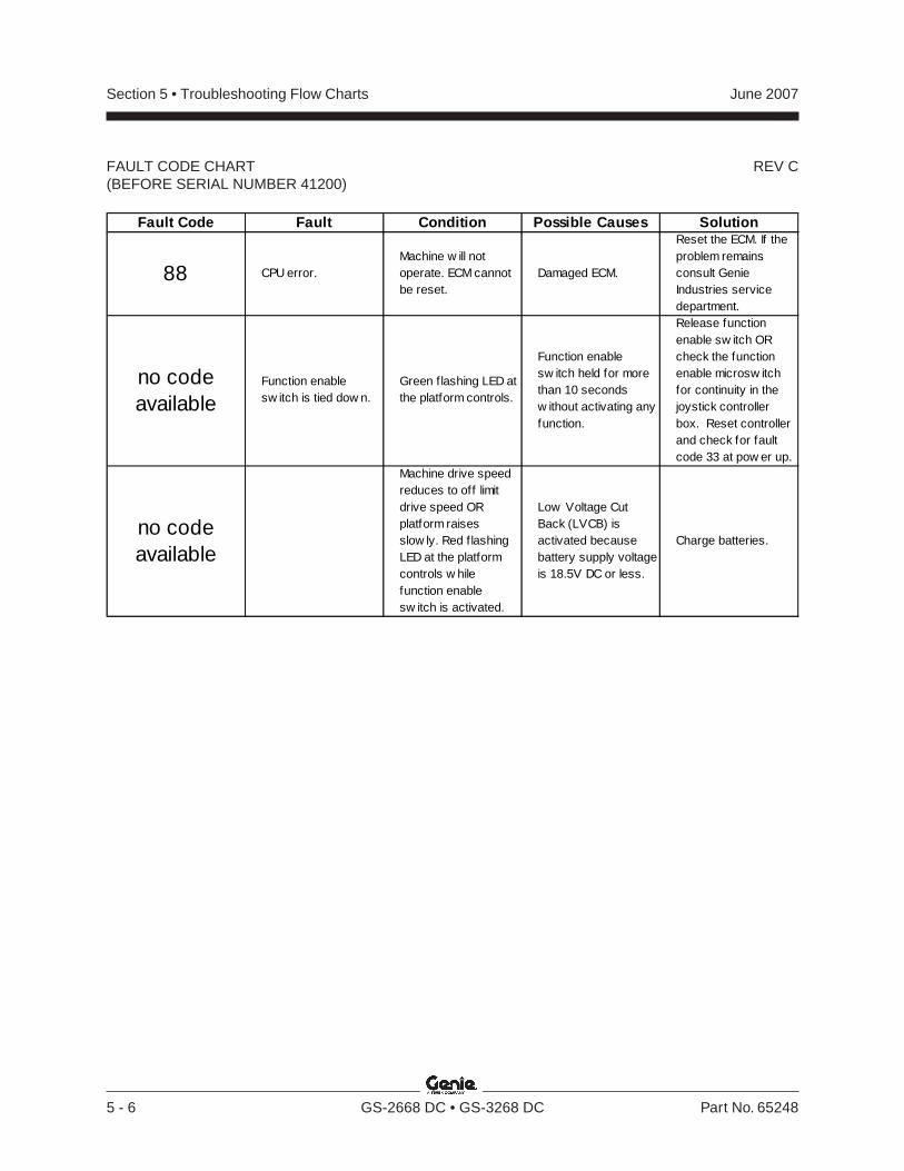
REV C
Section 5 • Troubleshooting Flow Charts June 2007
5 - 6 GS-2668 DC • GS-3268 DC Part No. 65248
FAULT CODE CHART(BEFORE SERIAL NUMBER 41200)
Fault Code Fault Condition Possible Causes Solution
88 CPU error.Machine w ill not operate. ECM cannot be reset.
Damaged ECM.
Reset the ECM. If the problem remains consult Genie Industries service department.
no code available
Function enable sw itch is tied dow n.
Green flashing LED at the platform controls.
Function enable sw itch held for more than 10 seconds w ithout activating any function.
Release function enable sw itch OR check the function enable microsw itch for continuity in the joystick controller box. Reset controller and check for fault code 33 at pow er up.
no code available
Machine drive speed reduces to off limit drive speed OR platform raises slow ly. Red flashing LED at the platform controls w hile function enable sw itch is activated.
Low Voltage Cut Back (LVCB) is activated because battery supply voltage is 18.5V DC or less.
Charge batteries.
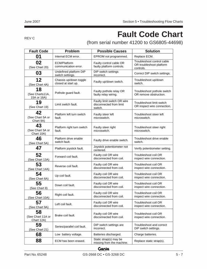
REV C
Section 5 • Troubleshooting Flow ChartsJune 2007
Part No. 65248 GS-2668 DC • GS-3268 DC 5 - 7
Fault Code Chart(from serial number 41200 to GS6805-44698)
Fault Code Problem Possible Causes Solution
01 Internal ECM error. EPROM not programmed. Replace ECM.
02(See Chart 20)
ECM/Platformcommunication error.
Faulty control cable ORfaulty platform controls.
Troubleshoot control cableOR troubleshoot platformcontrols.
03 Undefined platform DIPswitch settings.
DIP switch settingsincorrect. Correct DIP switch settings.
12(See Chart 4A)
Chassis up/down toggleclosed at start up. Faulty up/down switch. Troubleshoot up/down
switch.
18(See Charts11A,
15A or 16A)
Pothole guard fault. Faulty pothole relay ORfaulty relay wiring.
Troubleshoot pothole switchOR remove obstruction.
19(See Chart 19)
Limit switch fault.Faulty limit switch OR wiredisconnected from limitswitch.
Troubleshoot limit switchOR inspect wire connection.
42(See Chart 5A or
Chart 9A)
Platform left turn switchfault.
Faulty steer leftmicroswitch.
Troubleshoot steer leftmicroswitch.
43(See Chart 5A or
Chart 10A)
Platform right turn switchfault.
Faulty steer rightmicroswitch.
Troubleshoot steer rightmicroswitch.
46(See Chart 5A)
Platform drive enableswitch fault. Faulty drive enable switch. Troubleshoot drive enable
switch.
47 Platform joystick fault. Joystick potentiometer notcentered. Verify potentiometer setting.
52(See Chart 13A)
Forward coil fault. Faulty coil OR wiredisconnected from coil.
Troubleshoot coil ORinspect wire connection.
53(See Chart 14A)
Reverse coil fault. Faulty coil OR wiredisconnected from coil.
Troubleshoot coil ORinspect wire connection.
54(See Chart 6A)
Up coil fault. Faulty coil OR wiredisconnected from coil.
Troubleshoot coil ORinspect wire connection.
55(See Chart 8)
Down coil fault. Faulty coil OR wiredisconnected from coil.
Troubleshoot coil ORinspect wire connection.
56(See Chart 10A)
Right coil fault. Faulty coil OR wiredisconnected from coil.
Troubleshoot coil ORinspect wire connection.
57(See Chart 9A)
Left coil fault. Faulty coil OR wiredisconnected from coil.
Troubleshoot coil ORinspect wire connection.
58(See Chart 11A or
Chart 12A)
Brake coil fault. Faulty coil OR wiredisconnected from coil.
Troubleshoot coil ORinspect wire connection.
59(See Chart 21)
Series/parallel coil fault. DIP switch settings areincorrect.
Troubleshoot and correctDIP switch settings.
68 Low battery voltage. Batteries discharged. Charge batteries.
88 ECM has been erased. Static strap(s) may bemissing from the machine. Replace static strap(s).
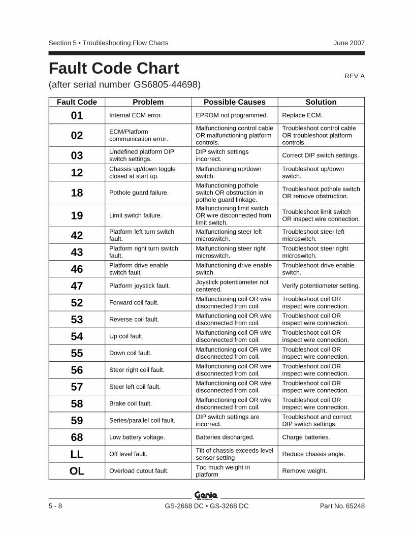
REV A
Section 5 • Troubleshooting Flow Charts June 2007
5 - 8 GS-2668 DC • GS-3268 DC Part No. 65248
Fault Code Chart(after serial number GS6805-44698)
Fault Code Problem Possible Causes Solution
01 Internal ECM error. EPROM not programmed. Replace ECM.
02 ECM/Platform communication error.
Malfunctioning control cable OR malfunctioning platform controls.
Troubleshoot control cable OR troubleshoot platform controls.
03 Undefined platform DIP switch settings.
DIP switch settings incorrect.
Correct DIP switch settings.
12 Chassis up/down toggle closed at start up.
Malfunctioning up/down switch.
Troubleshoot up/down switch.
18 Pothole guard failure. Malfunctioning pothole switch OR obstruction in pothole guard linkage.
Troubleshoot pothole switch OR remove obstruction.
19 Limit switch failure. Malfunctioning limit switch OR wire disconnected from limit switch.
Troubleshoot limit switch OR inspect wire connection.
42 Platform left turn switch fault.
Malfunctioning steer left microswitch.
Troubleshoot steer left microswitch.
43 Platform right turn switch fault.
Malfunctioning steer right microswitch.
Troubleshoot steer right microswitch.
46 Platform drive enable switch fault.
Malfunctioning drive enable switch.
Troubleshoot drive enable switch.
47 Platform joystick fault. Joystick potentiometer not centered.
Verify potentiometer setting.
52 Forward coil fault. Malfunctioning coil OR wire disconnected from coil.
Troubleshoot coil OR inspect wire connection.
53 Reverse coil fault. Malfunctioning coil OR wire disconnected from coil.
Troubleshoot coil OR inspect wire connection.
54 Up coil fault. Malfunctioning coil OR wire disconnected from coil.
Troubleshoot coil OR inspect wire connection.
55 Down coil fault. Malfunctioning coil OR wire disconnected from coil.
Troubleshoot coil OR inspect wire connection.
56 Steer right coil fault. Malfunctioning coil OR wire disconnected from coil.
Troubleshoot coil OR inspect wire connection.
57 Steer left coil fault. Malfunctioning coil OR wire disconnected from coil.
Troubleshoot coil OR inspect wire connection.
58 Brake coil fault. Malfunctioning coil OR wire disconnected from coil.
Troubleshoot coil OR inspect wire connection.
59 Series/parallel coil fault. DIP switch settings are incorrect.
Troubleshoot and correct DIP switch settings.
68 Low battery voltage. Batteries discharged. Charge batteries.
LL Off level fault. Tilt of chassis exceeds level sensor setting
Reduce chassis angle.
OL Overload cutout fault. Too much weight in platform
Remove weight.
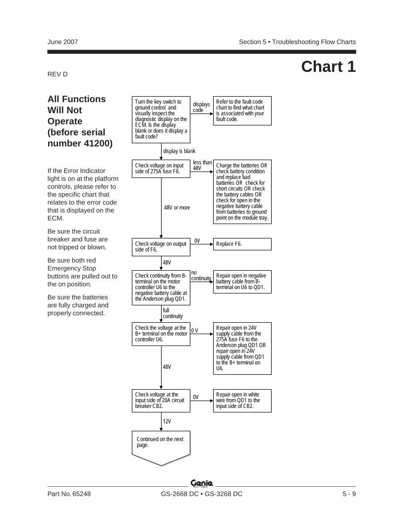
REV D
Section 5 • Troubleshooting Flow ChartsJune 2007
Part No. 65248 GS-2668 DC • GS-3268 DC 5 - 9
0V
Charge the batteries ORcheck battery conditionand replace badbatteries OR check forshort circuits OR checkthe battery cables ORcheck for open in thenegative battery cablefrom batteries to groundpoint on the module tray.
48V or more
Replace F6.
Continued on the nextpage.
48V
Check voltage on inputside of 275A fuse F6.
Check voltage on outputside of F6.
less than48V
Check continuity from B-terminal on the motorcontroller U6 to thenegative battery cable atthe Anderson plug QD1.
nocontinuity
fullcontinuity
Repair open in negativebattery cable from B-terminal on U6 to QD1.
Turn the key switch toground control andvisually inspect thediagnostic display on theECM. Is the displayblank or does it display afault code?
displayscode
display is blank
Refer to the fault codechart to find what chartis associated with yourfault code.
Check the voltage at theB+ terminal on the motorcontroller U6.
Repair open in 24Vsupply cable from the275A fuse F6 to theAnderson plug QD1 ORrepair open in 24Vsupply cable from QD1to the B+ terminal onU6.48V
0 V
Check voltage at theinput side of 20A circuitbreaker CB2.
0V
12V
Repair open in whitewire from QD1 to theinput side of CB2.
All FunctionsWill NotOperate(before serialnumber 41200)
If the Error Indicatorlight is on at the platformcontrols, please refer tothe specific chart thatrelates to the error codethat is displayed on theECM.
Be sure the circuitbreaker and fuse arenot tripped or blown.
Be sure both redEmergency Stopbuttons are pulled out tothe on position.
Be sure the batteriesare fully charged andproperly connected.
Chart 1

REV D
Section 5 • Troubleshooting Flow Charts June 2007
5 - 10 GS-2668 DC • GS-3268 DC Part No. 65248
Continued from theprevious page.
Check voltage at theinput side of eachcontact at the key switchKS1.
0VRepair open in the whtwire from PS1 to KS1OR repair open in whtwire jumper to eachcontact OR replace thecontact on the PS1 ORreplace PS1.
12V
Check voltage at whitewire at input side of theEmergency Stop buttonPS1.
0V
12V
Repair open in whitewire from the output sideof CB2 OR reset orreplace CB2.
Turn KS1 to platformcontrol and check theoutput side of eachcontact.
Check the cam on KS1. Repair or replace KS1.
good
Replace the badmicroswitch OR refer toPlatform ControlsInoperative, Chart 5 ORconsult the GenieIndustries ServiceDepartment.
12V
Refer to Chart 2, PumpMotor Will Not OperateOR repair open in whtwire (C2 estop chassis)OR consult the GenieIndustries ServiceDepartment.
0V
Turn the key switch KS1to the ground controlposition and check theoutput side of contact.
0V Check the cam on KS1. bad Repair or replace KS1.
good
Replace the contact ORrefer to Ground ControlsInoperative, Chart 4 ORconsult the GenieIndustries ServiceDepartment.
12V
bad
CHART 1

REV C
Section 5 • Troubleshooting Flow ChartsJune 2007
Part No. 65248 GS-2668 DC • GS-3268 DC 5 - 11
All FunctionsWill NotOperate(after serialnumber 41199)
If the Error Indicatorlight is on at the platformcontrols, please refer tothe specific chart thatrelates to the error codethat is displayed on theECM.
Be sure the circuitbreaker and fuse arenot tripped or blown.
Be sure both redEmergency Stopbuttons are pulled out tothe on position.
Be sure the batteriesare fully charged andproperly connected.
Chart 1A
Replace F6 OR checkfor short circuits ORcheck battery cables ORcheck for open innegative battery cablefrom batteries to groundpoint on module tray.20V or more
Continued on the nextpage.
Check voltage on theoutput side of the 275Afuse F6.
less than20V
Check voltage atterminal D1 at the pumpmotor M6.
Repair open in the 24Vcable circuit from F6 toQD1 OR replace orrepair QD1 OR repairopen in 24V cable circuitfrom QD1 throughterminal B+ at U6 toterminal D1 at M6.
20V or more
Check continuity fromthe B- terminal on themotor controller U6 tothe negative batterycable at QD1.
nocontinuity
continuity
Repair open in thenegative battery cablefrom the B- terminal atU6 to QD1.
With the key switchturned to platformcontrol and both redEmergency Stop buttonspulled out to the onposition, press and holdthe function enableswitch. Visually inspectthe power-on LED.
light is on
light is not on
Troubleshoot groundand platform controlsystems separately ORconsult the GenieIndustries ServiceDepartment.
0V
Troubleshoot the CR48power relay to U5.
good
bad Repair or replace thewire circuit from theplatform controls toCR48 OR repair orreplace the CR48 socketOR replace CR48.
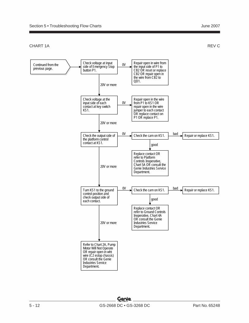
REV C
Section 5 • Troubleshooting Flow Charts June 2007
5 - 12 GS-2668 DC • GS-3268 DC Part No. 65248
CHART 1A
Continued from theprevious page.
Check voltage at theinput side of eachcontact at key switchKS1.
Repair open in the wirefrom P1 to KS1 ORrepair open in the wirejumper to each contactOR replace contact onP1 OR replace P1.
20V or more
Check the output side ofthe platform controlcontact at KS1.
Check the cam on KS1. bad Repair or replace KS1.
good
Replace contact ORrefer to Ground ControlsInoperative, Chart 4AOR consult the GenieIndustries ServiceDepartment.
20V or more
0V
0V
Turn KS1 to the groundcontrol position andcheck output side ofeach contact.
Replace contact ORrefer to PlatformControls Inoperative,Chart 5A OR consult theGenie Industries ServiceDepartment.
20V or more
Refer to Chart 2A, PumpMotor Will Not OperateOR repair open in whtwire (C2 estop chassis)OR consult the GenieIndustries ServiceDepartment.
0V Check the cam on KS1. bad Repair or replace KS1.
good
Check voltage at inputside of Emergency Stopbutton P1.
0V
20V or more
Repair open in wire fromthe input side of P1 toCB2 OR reset or replaceCB2 OR repair open inthe wire from CB2 toQD1.
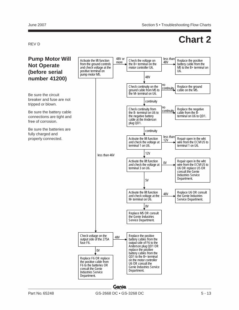
REV D
Section 5 • Troubleshooting Flow ChartsJune 2007
Part No. 65248 GS-2668 DC • GS-3268 DC 5 - 13
Activate the lift functionfrom the ground controlsand check voltage at thepositive terminal onpump motor M5.
48V ormore
Check continuity on theground cable from M5 tothe M- terminal on U6.
nocontinuity
continuity
Replace the groundcable on the M5.
less than 46V
Activate the lift functionand check the voltage atterminal 1 on U6.
12V
Replace the negativecable from the B-terminal on U6 to QD1.
Check continuity fromthe B- terminal on U6 tothe negative batterycable at the Andersonplug QD1.
continuity
nocontinuity
Repair open in the whtwire from the ECM U5 toterminal 1 on U6.
Activate the lift functionand check the voltage atterminal 3 on U6.
Repair open in the whtwire from the ECM U5 toU6 OR replace U5 ORconsult the GenieIndustries ServiceDepartment.
0V
5V
Replace M5 OR consultthe Genie IndustriesService Department.
Check the voltage onthe B+ terminal on themotor controller U6.
less than48V Replace the positive
battery cable from theM5 to the B+ terminal onU6.
48V
Activate the lift functionand check voltage at theM- terminal on U6.
48V
0V
Replace U6 OR consultthe Genie IndustriesService Department.
less than12V
Check voltage on theoutput side of the 275Afuse F6.
Replace F6 OR replacethe positive cable fromF6 to the batteries ORconsult the GenieIndustries ServiceDepartment.
Replace the positivebattery cables from theoutput side of F6 to theAnderson plug QD1 ORreplace the positivebattery cables from theQD1 to the B+ terminalon the motor controllerU6 OR consult theGenie Industries ServiceDepartment.
48V
0V
Chart 2
Pump Motor WillNot Operate(before serialnumber 41200)
Be sure the circuitbreaker and fuse are nottripped or blown.
Be sure the battery cableconnections are tight andfree of corrosion.
Be sure the batteries arefully charged andproperly connected.
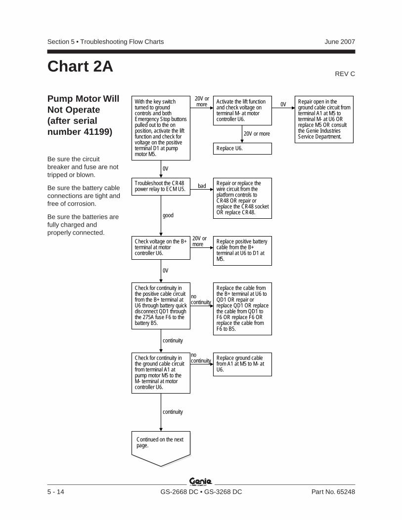
REV C
Section 5 • Troubleshooting Flow Charts June 2007
5 - 14 GS-2668 DC • GS-3268 DC Part No. 65248
With the key switchturned to groundcontrols and bothEmergency Stop buttonspulled out to the onposition, activate the liftfunction and check forvoltage on the positiveterminal D1 at pumpmotor M5.
20V ormore
Check for continuity inthe ground cable circuitfrom terminal A1 atpump motor M5 to theM- terminal at motorcontroller U6.
nocontinuity
continuity
Replace ground cablefrom A1 at M5 to M- atU6.
0V
Continued on the nextpage.
Check voltage on the B+terminal at motorcontroller U6.
20V ormore Replace positive battery
cable from the B+terminal at U6 to D1 atM5.
0V
Replace the cable fromthe B+ terminal at U6 toQD1 OR repair orreplace QD1 OR replacethe cable from QD1 toF6 OR replace F6 ORreplace the cable fromF6 to B5.
Check for continuity inthe positive cable circuitfrom the B+ terminal atU6 through battery quickdisconnect QD1 throughthe 275A fuse F6 to thebattery B5.
continuity
nocontinuity
0V
20V or more
Activate the lift functionand check voltage onterminal M- at motorcontroller U6.
Repair open in theground cable circuit fromterminal A1 at M5 toterminal M- at U6 ORreplace M5 OR consultthe Genie IndustriesService Department.
Replace U6.
Troubleshoot the CR48power relay to ECM U5.
good
bad Repair or replace thewire circuit from theplatform controls toCR48 OR repair orreplace the CR48 socketOR replace CR48.
Chart 2A
Pump Motor WillNot Operate(after serialnumber 41199)
Be sure the circuitbreaker and fuse are nottripped or blown.
Be sure the battery cableconnections are tight andfree of corrosion.
Be sure the batteries arefully charged andproperly connected.
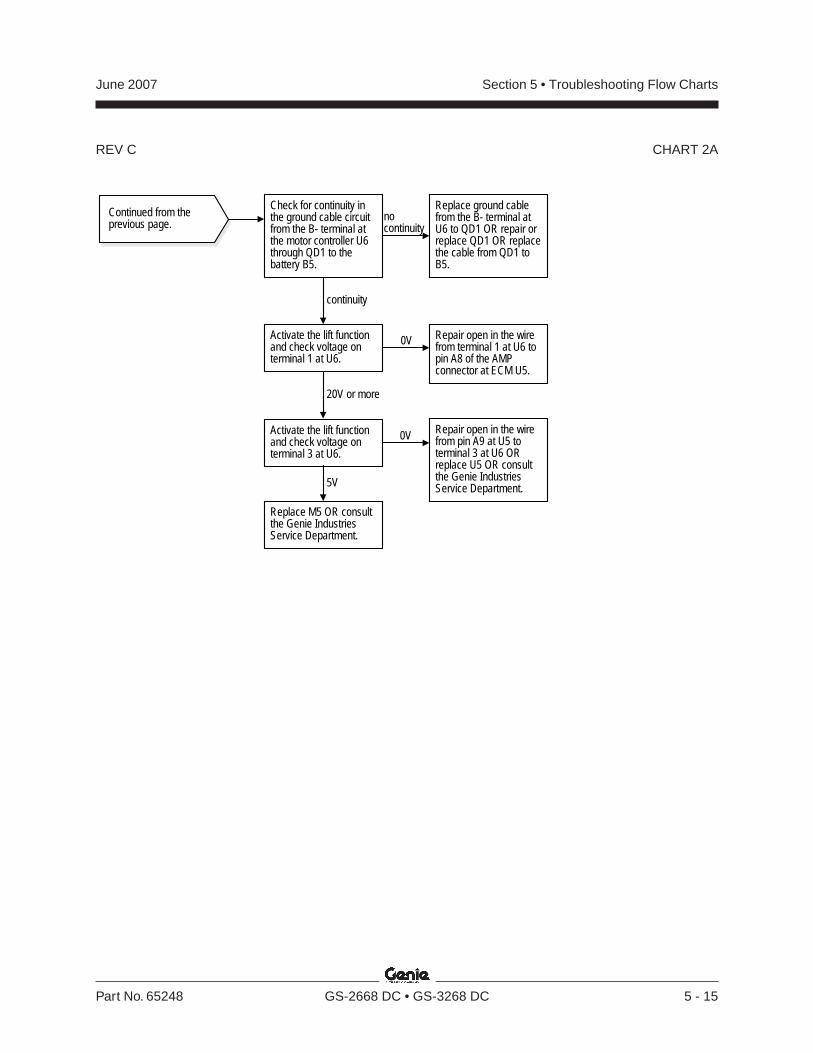
REV C
Section 5 • Troubleshooting Flow ChartsJune 2007
Part No. 65248 GS-2668 DC • GS-3268 DC 5 - 15
CHART 2A
Continued from theprevious page.
Activate the lift functionand check voltage onterminal 1 at U6.
20V or more
Replace ground cablefrom the B- terminal atU6 to QD1 OR repair orreplace QD1 OR replacethe cable from QD1 toB5.
Check for continuity inthe ground cable circuitfrom the B- terminal atthe motor controller U6through QD1 to thebattery B5.
nocontinuity
Repair open in the wirefrom terminal 1 at U6 topin A8 of the AMPconnector at ECM U5.
Activate the lift functionand check voltage onterminal 3 at U6.
Repair open in the wirefrom pin A9 at U5 toterminal 3 at U6 ORreplace U5 OR consultthe Genie IndustriesService Department.
0V
5V
Replace M5 OR consultthe Genie IndustriesService Department.
0V
continuity
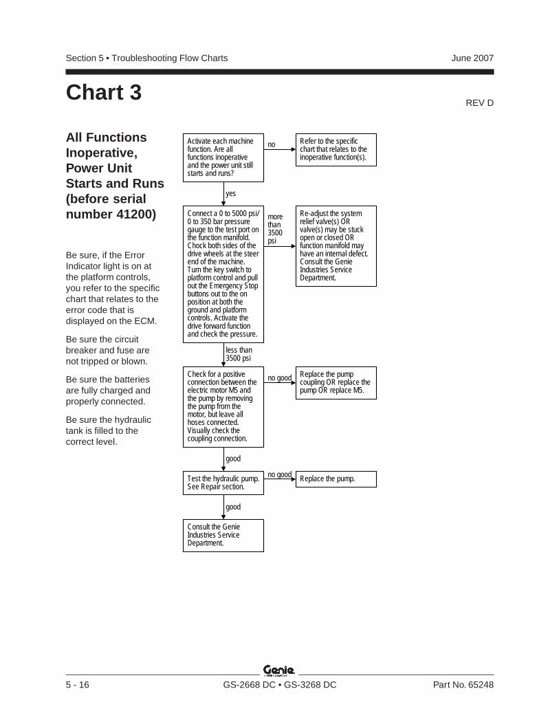
REV D
Section 5 • Troubleshooting Flow Charts June 2007
5 - 16 GS-2668 DC • GS-3268 DC Part No. 65248
Chart 3
All FunctionsInoperative,Power UnitStarts and Runs(before serialnumber 41200)
Be sure, if the ErrorIndicator light is on atthe platform controls,you refer to the specificchart that relates to theerror code that isdisplayed on the ECM.
Be sure the circuitbreaker and fuse arenot tripped or blown.
Be sure the batteriesare fully charged andproperly connected.
Be sure the hydraulictank is filled to thecorrect level.
Check for a positiveconnection between theelectric motor M5 andthe pump by removingthe pump from themotor, but leave allhoses connected.Visually check thecoupling connection.
no good Replace the pumpcoupling OR replace thepump OR replace M5.
good
Test the hydraulic pump.See Repair section.
Consult the GenieIndustries ServiceDepartment.
no good Replace the pump.
good
Activate each machinefunction. Are allfunctions inoperativeand the power unit stillstarts and runs?
no
yes
Refer to the specificchart that relates to theinoperative function(s).
Connect a 0 to 5000 psi/0 to 350 bar pressuregauge to the test port onthe function manifold.Chock both sides of thedrive wheels at the steerend of the machine.Turn the key switch toplatform control and pullout the Emergency Stopbuttons out to the onposition at both theground and platformcontrols. Activate thedrive forward functionand check the pressure.
morethan3500psi
less than3500 psi
Re-adjust the systemrelief valve(s) ORvalve(s) may be stuckopen or closed ORfunction manifold mayhave an internal defect.Consult the GenieIndustries ServiceDepartment.
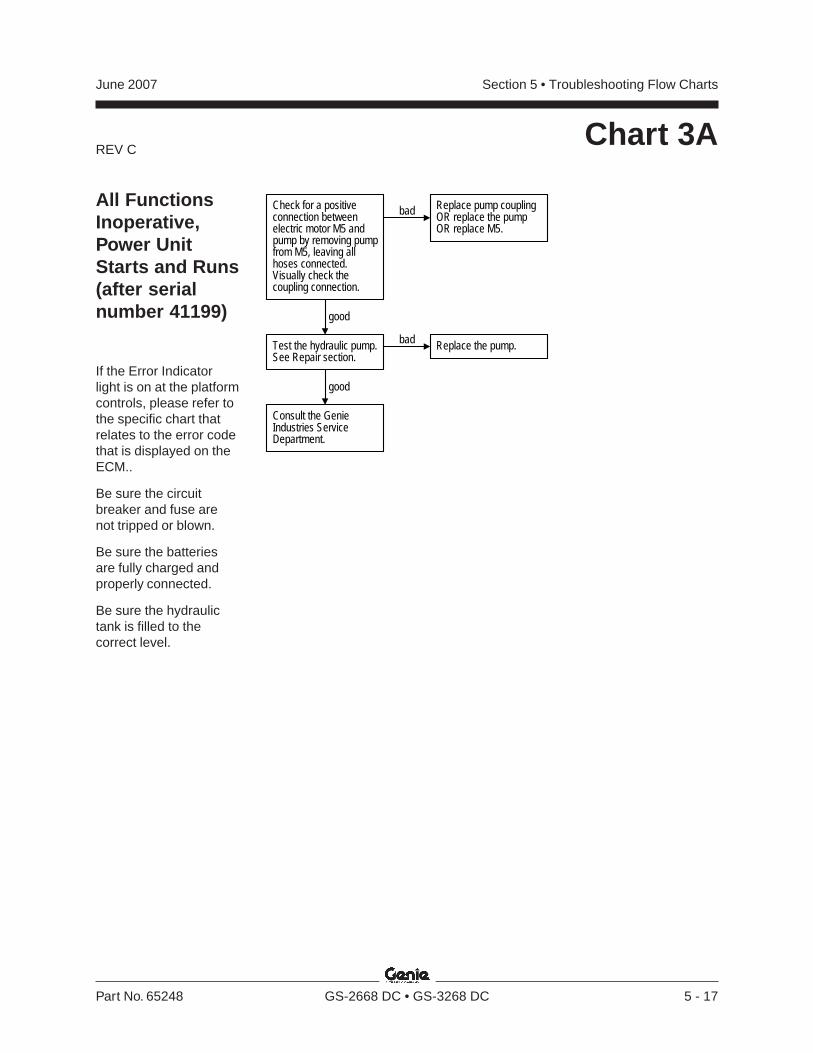
REV C
Section 5 • Troubleshooting Flow ChartsJune 2007
Part No. 65248 GS-2668 DC • GS-3268 DC 5 - 17
Chart 3A
All FunctionsInoperative,Power UnitStarts and Runs(after serialnumber 41199)
If the Error Indicatorlight is on at the platformcontrols, please refer tothe specific chart thatrelates to the error codethat is displayed on theECM..
Be sure the circuitbreaker and fuse arenot tripped or blown.
Be sure the batteriesare fully charged andproperly connected.
Be sure the hydraulictank is filled to thecorrect level.
Check for a positiveconnection betweenelectric motor M5 andpump by removing pumpfrom M5, leaving allhoses connected.Visually check thecoupling connection.
bad Replace pump couplingOR replace the pumpOR replace M5.
good
Test the hydraulic pump.See Repair section.
Consult the GenieIndustries ServiceDepartment.
bad Replace the pump.
good
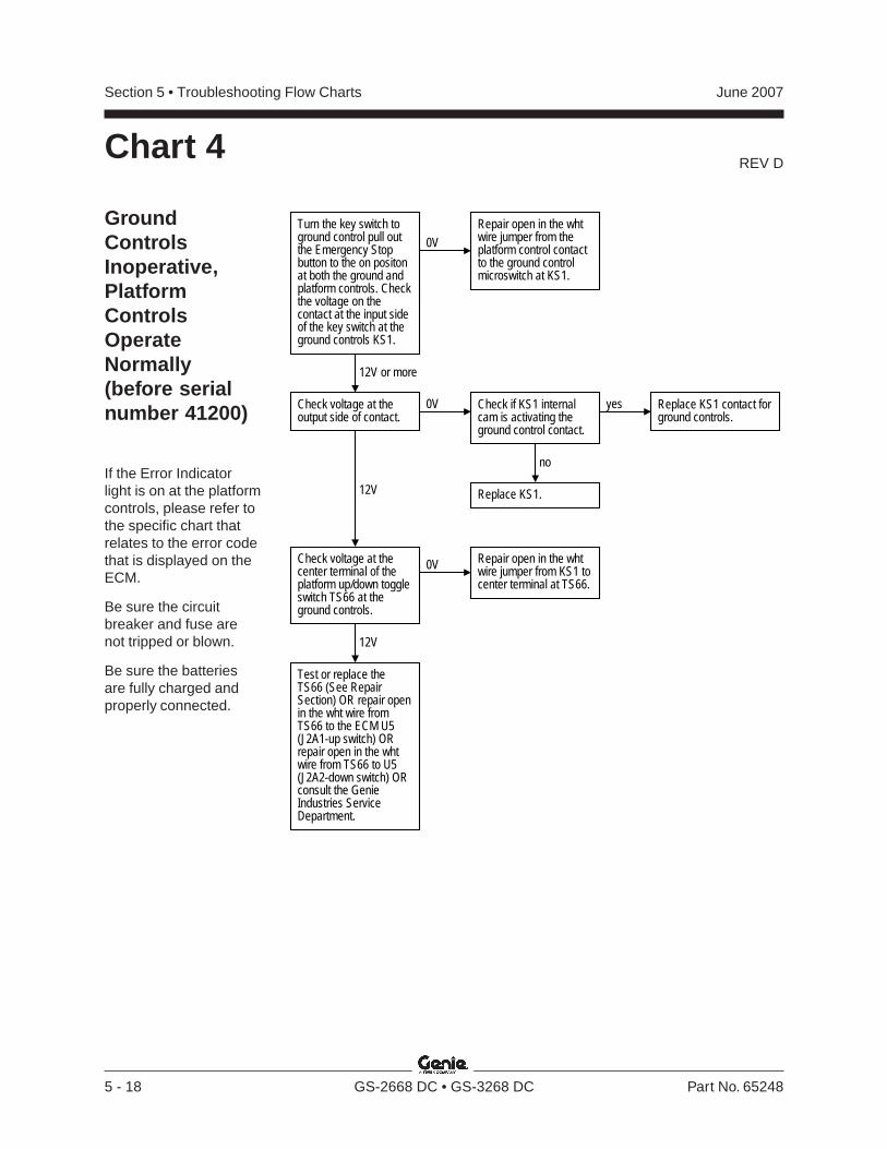
REV D
Section 5 • Troubleshooting Flow Charts June 2007
5 - 18 GS-2668 DC • GS-3268 DC Part No. 65248
Turn the key switch toground control pull outthe Emergency Stopbutton to the on positonat both the ground andplatform controls. Checkthe voltage on thecontact at the input sideof the key switch at theground controls KS1.
0VRepair open in the whtwire jumper from theplatform control contactto the ground controlmicroswitch at KS1.
12V or more
Check voltage at theoutput side of contact.
0V Check if KS1 internalcam is activating theground control contact.
yes Replace KS1 contact forground controls.
no
Replace KS1.12V
Repair open in the whtwire jumper from KS1 tocenter terminal at TS66.
Check voltage at thecenter terminal of theplatform up/down toggleswitch TS66 at theground controls.
0V
12V
Test or replace theTS66 (See RepairSection) OR repair openin the wht wire fromTS66 to the ECM U5(J2A1-up switch) ORrepair open in the whtwire from TS66 to U5(J2A2-down switch) ORconsult the GenieIndustries ServiceDepartment.
GroundControlsInoperative,PlatformControlsOperateNormally(before serialnumber 41200)
If the Error Indicatorlight is on at the platformcontrols, please refer tothe specific chart thatrelates to the error codethat is displayed on theECM.
Be sure the circuitbreaker and fuse arenot tripped or blown.
Be sure the batteriesare fully charged andproperly connected.
Chart 4
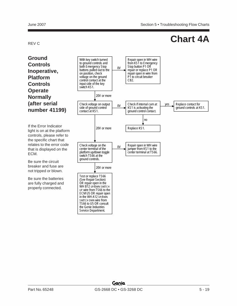
REV C
Section 5 • Troubleshooting Flow ChartsJune 2007
Part No. 65248 GS-2668 DC • GS-3268 DC 5 - 19
GroundControlsInoperative,PlatformControlsOperateNormally(after serialnumber 41199)
If the Error Indicatorlight is on at the platformcontrols, please refer tothe specific chart thatrelates to the error codethat is displayed on theECM.
Be sure the circuitbreaker and fuse arenot tripped or blown.
Be sure the batteriesare fully charged andproperly connected.
Chart 4A
With key switch turnedto ground controls andboth Emergency Stopbuttons pulled out to theon position, checkvoltage on the groundcontrol contact at theinput side of the keyswitch KS1.
0V
Repair open in WH wirefrom KS1 to EmergencyStop button P1 ORrepair or replace P1 ORrepair open in wire fromP1 to circuit breakerCB2.
20V or more
Check voltage on outputside of ground controlcontact at KS1.
Check if internal cam atKS1 is activating theground control contact.
yes Replace contact forground controls at KS1.
no
Replace KS1.20V or more
Repair open in WH wirejumper from KS1 to thecenter terminal at TS66.
Check voltage on thecenter terminal of theplatform up/down toggleswitch TS66 at theground controls.
0V
20V or more
Test or replace TS66(See Repair Section)OR repair open in theWH B12 UP/DWN SWITCHUP wire from TS66 to theECM U5 OR repair openin the WH A12 UP/DWNSWITCH DWN wire fromTS66 to U5 OR consultthe Genie IndustriesService Department.
0V
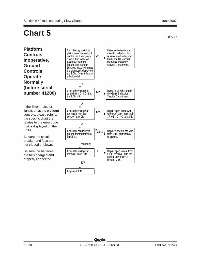
REV D
Section 5 • Troubleshooting Flow Charts June 2007
5 - 20 GS-2668 DC • GS-3268 DC Part No. 65248
Chart 5
PlatformControlsInoperative,GroundControlsOperateNormally(before serialnumber 41200)
If the Error Indicatorlight is on at the platformcontrols, please refer tothe specific chart thatrelates to the error codethat is displayed on theECM.
Be sure the circuitbreaker and fuse arenot tripped or blown.
Be sure the batteriesare fully charged andproperly connected.
Check the voltage onwht wire J1-C11,C12 atthe ECM U5.
Replace U5 OR contactthe Genie IndustriesService Department.
0V
Check the voltage atterminal 87 on thecontrol relay CR41.
12V Repair open in the whtwire from CR41 terminal87 to J1-C11,C12 at U5.
Check for continuity toground from terminal 85on CR41.
0V
12V
Turn the key switch toplatform control and pullout the red EmergencyStop button to the onpositon at both theground and platformcontrols. Visually inspectthe diagnostic display onthe ECM. Does it displaya fault code?
yes
no
Refer to the fault codechart to find what chartis associated with yourfault code OR consultthe Genie IndustriesService Department.
continuity
nocontinuity Replace open in the wire
from CR41 terminal 85to ground.
Check the voltage atterminal 30 on CR41.
Repair open in wire fromCR41 terminal 30 to theoutput side of circuitbreaker CB6.
0V
12V
Replace CR41.
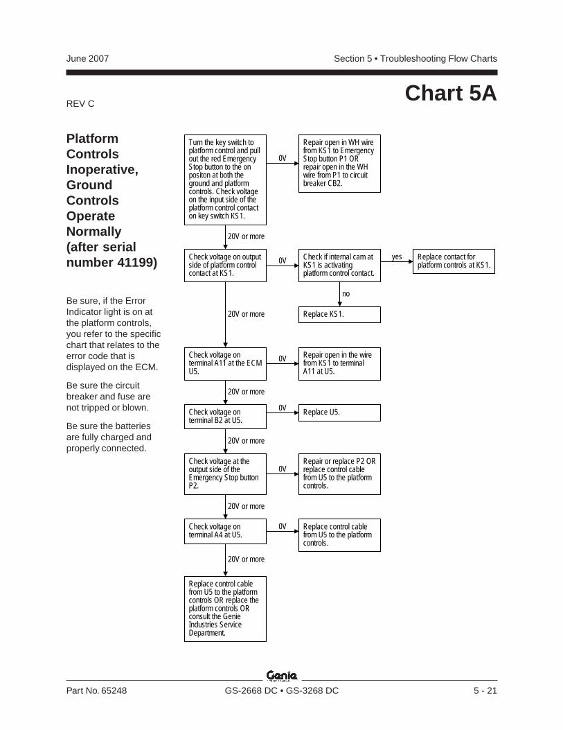
REV C
Section 5 • Troubleshooting Flow ChartsJune 2007
Part No. 65248 GS-2668 DC • GS-3268 DC 5 - 21
Chart 5A
PlatformControlsInoperative,GroundControlsOperateNormally(after serialnumber 41199)
Be sure, if the ErrorIndicator light is on atthe platform controls,you refer to the specificchart that relates to theerror code that isdisplayed on the ECM.
Be sure the circuitbreaker and fuse arenot tripped or blown.
Be sure the batteriesare fully charged andproperly connected.
Turn the key switch toplatform control and pullout the red EmergencyStop button to the onpositon at both theground and platformcontrols. Check voltageon the input side of theplatform control contacton key switch KS1.
0V
Repair open in WH wirefrom KS1 to EmergencyStop button P1 ORrepair open in the WHwire from P1 to circuitbreaker CB2.
20V or more
Check voltage on outputside of platform controlcontact at KS1.
0V Check if internal cam atKS1 is activatingplatform control contact.
yes Replace contact forplatform controls at KS1.
no
Replace KS1.20V or more
Repair or replace P2 ORreplace control cablefrom U5 to the platformcontrols.
Check voltage at theoutput side of theEmergency Stop buttonP2.
0V
20V or more
Check voltage onterminal B2 at U5.
0V Replace U5.
Check voltage onterminal A11 at the ECMU5.
0V Repair open in the wirefrom KS1 to terminalA11 at U5.
20V or more
20V or more
20V or more
Check voltage onterminal A4 at U5.
0V Replace control cablefrom U5 to the platformcontrols.
Replace control cablefrom U5 to the platformcontrols OR replace theplatform controls ORconsult the GenieIndustries ServiceDepartment.
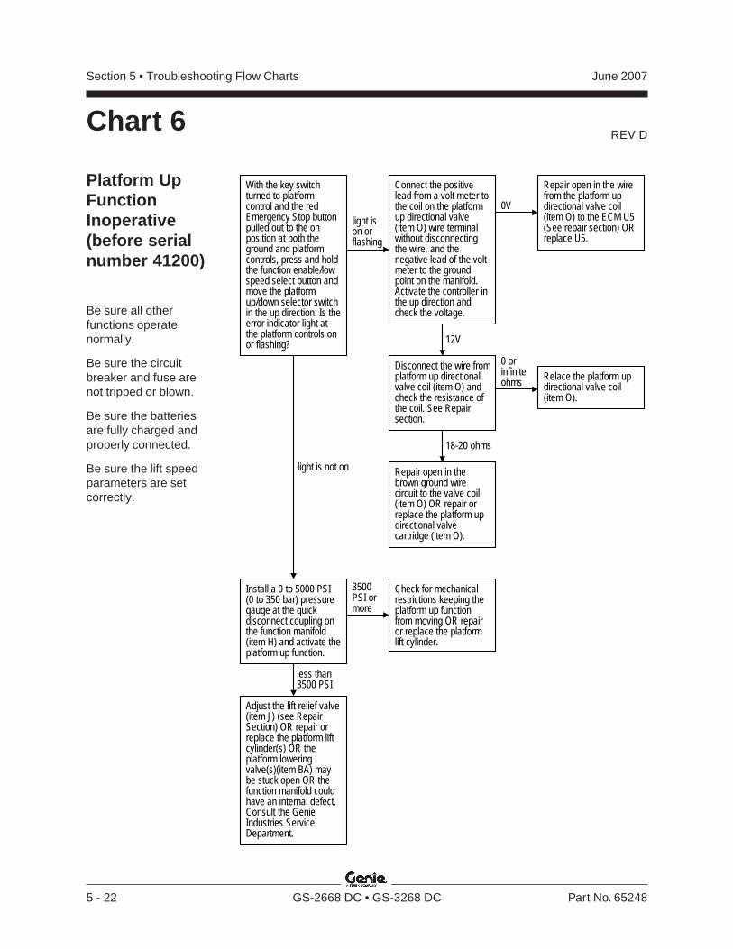
REV D
Section 5 • Troubleshooting Flow Charts June 2007
5 - 22 GS-2668 DC • GS-3268 DC Part No. 65248
With the key switchturned to platformcontrol and the redEmergency Stop buttonpulled out to the onposition at both theground and platformcontrols, press and holdthe function enable/lowspeed select button andmove the platformup/down selector switchin the up direction. Is theerror indicator light atthe platform controls onor flashing?
light ison orflashing
light is not on
18-20 ohms
Install a 0 to 5000 PSI(0 to 350 bar) pressuregauge at the quickdisconnect coupling onthe function manifold(item H) and activate theplatform up function.
3500PSI ormore
less than3500 PSI
Adjust the lift relief valve(item J) (see RepairSection) OR repair orreplace the platform liftcylinder(s) OR theplatform loweringvalve(s)(item BA) maybe stuck open OR thefunction manifold couldhave an internal defect.Consult the GenieIndustries ServiceDepartment.
Repair open in thebrown ground wirecircuit to the valve coil(item O) OR repair orreplace the platform updirectional valvecartridge (item O).
Check for mechanicalrestrictions keeping theplatform up functionfrom moving OR repairor replace the platformlift cylinder.
Connect the positivelead from a volt meter tothe coil on the platformup directional valve(item O) wire terminalwithout disconnectingthe wire, and thenegative lead of the voltmeter to the groundpoint on the manifold.Activate the controller inthe up direction andcheck the voltage.
0V
Repair open in the wirefrom the platform updirectional valve coil(item O) to the ECM U5(See repair section) ORreplace U5.
12V
Disconnect the wire fromplatform up directionalvalve coil (item O) andcheck the resistance ofthe coil. See Repairsection.
Relace the platform updirectional valve coil(item O).
0 orinfiniteohms
Platform UpFunctionInoperative(before serialnumber 41200)
Be sure all otherfunctions operatenormally.
Be sure the circuitbreaker and fuse arenot tripped or blown.
Be sure the batteriesare fully charged andproperly connected.
Be sure the lift speedparameters are setcorrectly.
Chart 6
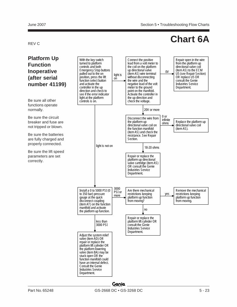
REV C
Section 5 • Troubleshooting Flow ChartsJune 2007
Part No. 65248 GS-2668 DC • GS-3268 DC 5 - 23
Platform UpFunctionInoperative(after serialnumber 41199)
Be sure all otherfunctions operatenormally.
Be sure the circuitbreaker and fuse arenot tripped or blown.
Be sure the batteriesare fully charged andproperly connected.
Be sure the lift speedparameters are setcorrectly.
Chart 6A
With the key switchturned to platformcontrols and bothEmergency Stop buttonspulled out to the onposition, press the liftfunction select buttonand activate thecontroller in the updirection and check tosee if the error indicatorlight at the platformcontrols is on.
light ison
light is not on
Connect the positivelead from a volt meter tothe coil on the platformup directional valve(item AS) wire terminalwithout disconnectingthe wire and thenegative lead of the voltmeter to the groundpoint on the manifold.Activate the controller inthe up direction andcheck the voltage.
Disconnect the wire fromthe platform updirectional valve coil onthe function manifold(item AS) and check theresistance. See RepairSection.
0V
Repair open in the wirefrom the platform updirectional valve coil(item AS) to the ECMU5 (see Repair Section)OR replace U5 ORconsult the GenieIndustries ServiceDepartment.
20V or more
0 orinfiniteohms
18-20 ohms
Replace the platform updirectional valve coil(item AS).
Repair or replace theplatform up directionalvalve cartridge (item AS)OR consult the GenieIndustries ServiceDepartment.
Install a 0 to 5000 PSI (0to 350 bar) pressuregauge at the quickdisconnect coupling(item AT) on the functionmanifold and activatethe platform up function.
3000PSI ormore
less than3000 PSI
Adjust the system reliefvalve (item AD) ORrepair or replace theplatform lift cylinder ORthe platform loweringvalve (item BA) may bestuck open OR thefunction manifold couldhave an internal defect.Consult the GenieIndustries ServiceDepartment.
Are there mechanicalrestrictions keepingplatform up functionfrom moving?
Remove the mechanicalrestrictions keepingplatform up functionfrom moving.
Repair or replace theplatform lift cylinder ORconsult the GenieIndustries ServiceDepartment.
yes
no
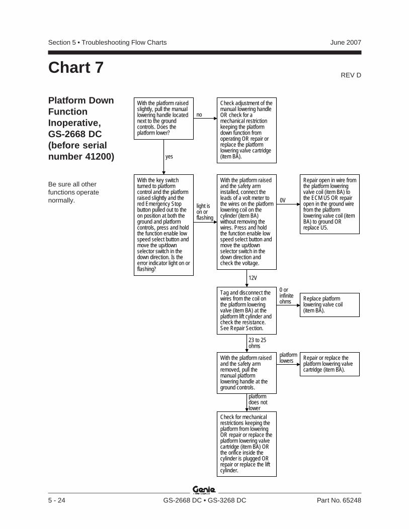
REV D
Section 5 • Troubleshooting Flow Charts June 2007
5 - 24 GS-2668 DC • GS-3268 DC Part No. 65248
Chart 7
Platform DownFunctionInoperative,GS-2668 DC(before serialnumber 41200)
Be sure all otherfunctions operatenormally.
Repair or replace theplatform lowering valvecartridge (item BA).
With the key switchturned to platformcontrol and the platformraised slightly and thered Emergency Stopbutton pulled out to theon position at both theground and platformcontrols, press and holdthe function enable lowspeed select button andmove the up/downselector switch in thedown direction. Is theerror indicator light on orflashing?
light ison orflashing
0V
12V
Repair open in wire fromthe platform loweringvalve coil (item BA) tothe ECM U5 OR repairopen in the ground wirefrom the platformlowering valve coil (itemBA) to ground ORreplace U5.
Check for mechanicalrestrictions keeping theplatform from loweringOR repair or replace theplatform lowering valvecartridge (item BA) ORthe orifice inside thecylinder is plugged ORrepair or replace the liftcylinder.
Tag and disconnect thewires from the coil onthe platform loweringvalve (item BA) at theplatform lift cylinder andcheck the resistance.See Repair Section.
23 to 25ohms
0 orinfiniteohms
With the platform raisedand the safety arminstalled, connect theleads of a volt meter tothe wires on the platformlowering coil on thecylinder (item BA)without removing thewires. Press and holdthe function enable lowspeed select button andmove the up/downselector switch in thedown direction andcheck the voltage.
Replace platformlowering valve coil(item BA).
With the platform raisedand the safety armremoved, pull themanual platformlowering handle at theground controls.
platformlowers
platformdoes notlower
With the platform raisedslightly, pull the manuallowering handle locatednext to the groundcontrols. Does theplatform lower?
yes
no
Check adjustment of themanual lowering handleOR check for amechanical restrictionkeeping the platformdown function fromoperating OR repair orreplace the platformlowering valve cartridge(item BA).
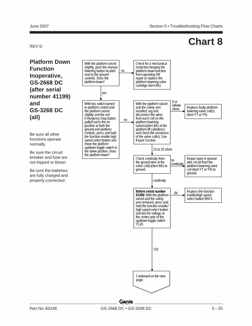
REV D
Section 5 • Troubleshooting Flow ChartsJune 2007
Part No. 65248 GS-2668 DC • GS-3268 DC 5 - 25
Chart 8
Platform DownFunctionInoperative,GS-2668 DC(after serialnumber 41199)andGS-3268 DC(all)
Be sure all otherfunctions operatenormally.
Be sure the circuitbreaker and fuse arenot tripped or blown.
Be sure the batteriesare fully charged andproperly connected.
With the platform raisedslightly, push the manuallowering button locatednext to the groundcontrols. Does theplatform lower?
yes
no
Check for a mechanicalrestriction keeping theplatform down functionfrom operating ORrepair or replace theplatform lowering valvecartridge (item BA).
no
With the platform raisedand the safety arminstalled, tag anddisconnect the wiresfrom each coil on theplatform loweringvalve(s)(item BA) at theplatform lift cylinder(s)and check the resistanceof the valve coil(s). SeeRepair Section.
0 orinfiniteohms
23 to 25 ohms
Replace faulty platformlowering valve coil(s)(item Y7 or Y9).
Before serial number41200: With the platformraised and the safetyarm removed, press andhold the function enable/high speed select buttonand test for voltage atthe center pole of theup/down toggle switchTS20.
12V
0V
Continued on the nextpage.
Check continuity fromthe ground wire at thevalve coil(s)(item BA) toground.
nocontinuity
continuity
Repair open in groundwire circuit from theplatform lowering valvecoil (item Y7 or Y9) toground.
With key switch turnedto platform control andthe platform raisedslightly and the redEmergency Stop buttonpulled out to the onposition at both theground and platformcontrols, press and holdthe function enable highspeed select button andmove the platformup/down toggle switch inthe down position. Doesthe platform lower?
Replace the functionenable/high speedselect button BN13.
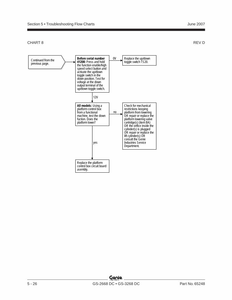
REV D
Section 5 • Troubleshooting Flow Charts June 2007
5 - 26 GS-2668 DC • GS-3268 DC Part No. 65248
Continued from theprevious page.
Before serial number41200: Press and holdthe function enable/highspeed select button andactivate the up/downtoggle switch in thedown position. Test forvoltage at the downoutput terminal of theup/down toggle switch.
12V
0V Replace the up/downtoggle switch TS20.
Check for mechanicalrestrictions keepingplatform from loweringOR repair or replace theplatform lowering valvecartridge(s) (item BA)OR the orifice inside thecylinder(s) is pluggedOR repair or replace thelift cylinder(s) ORconsult the GenieIndustries ServiceDepartment.
All models: Using aplatform control boxfrom a functionalmachine, test the downfuction. Does theplatform lower?
no
yes
Replace the platformcontrol box circuit boardasembly.
CHART 8
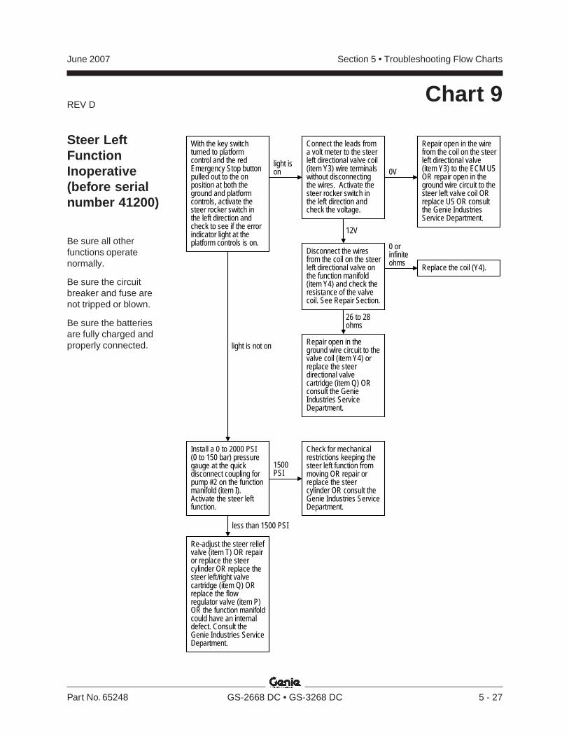
REV D
Section 5 • Troubleshooting Flow ChartsJune 2007
Part No. 65248 GS-2668 DC • GS-3268 DC 5 - 27
Chart 9
Steer LeftFunctionInoperative(before serialnumber 41200)
Be sure all otherfunctions operatenormally.
Be sure the circuitbreaker and fuse arenot tripped or blown.
Be sure the batteriesare fully charged andproperly connected.
With the key switchturned to platformcontrol and the redEmergency Stop buttonpulled out to the onposition at both theground and platformcontrols, activate thesteer rocker switch inthe left direction andcheck to see if the errorindicator light at theplatform controls is on.
light ison
light is not on
Disconnect the wiresfrom the coil on the steerleft directional valve onthe function manifold(item Y4) and check theresistance of the valvecoil. See Repair Section.
0V
Repair open in the wirefrom the coil on the steerleft directional valve(item Y3) to the ECM U5OR repair open in theground wire circuit to thesteer left valve coil ORreplace U5 OR consultthe Genie IndustriesService Department.
12V
0 orinfiniteohms Replace the coil (Y4).
Repair open in theground wire circuit to thevalve coil (item Y4) orreplace the steerdirectional valvecartridge (item Q) ORconsult the GenieIndustries ServiceDepartment.
Install a 0 to 2000 PSI(0 to 150 bar) pressuregauge at the quickdisconnect coupling forpump #2 on the functionmanifold (item I).Activate the steer leftfunction.
1500PSI
less than 1500 PSI
Check for mechanicalrestrictions keeping thesteer left function frommoving OR repair orreplace the steercylinder OR consult theGenie Industries ServiceDepartment.
Connect the leads froma volt meter to the steerleft directional valve coil(item Y3) wire terminalswithout disconnectingthe wires. Activate thesteer rocker switch inthe left direction andcheck the voltage.
26 to 28ohms
Re-adjust the steer reliefvalve (item T) OR repairor replace the steercylinder OR replace thesteer left/right valvecartridge (item Q) ORreplace the flowregulator valve (item P)OR the function manifoldcould have an internaldefect. Consult theGenie Industries ServiceDepartment.

REV C
Section 5 • Troubleshooting Flow Charts June 2007
5 - 28 GS-2668 DC • GS-3268 DC Part No. 65248
Chart 9A
Steer LeftFunctionInoperative(after serialnumber 41200)
Be sure all otherfunctions operatenormally.
Be sure the circuitbreaker and fuse arenot tripped or blown.
Be sure the batteriesare fully charged andproperly connected.
no
With the key switchturned to platformcontrols and bothEmergency Stop buttonspulled out to the onposition, press the drivefunction select buttonand activate the functionenable switch andactivate the steer rockerswitch in the leftdirection and check tosee if the error indicatorlight at the platformcontrols is on.
light ison
light is not on
Disconnect the wiresfrom the coil on the steerleft directional valve onthe function manifold(item Y4) and check theresistance of the valvecoil (See Repairsection).
0V
Repair open in the wirefrom the coil on the steerleft directional valve(item Y4) to the ECM U5OR repair open in theground wire circuit fromthe coil to the wireharness OR replace U5OR consult the GenieIndustries ServiceDepartment.
20V or more
25 to 27ohms
0 or infiniteohms
Replace the steer leftdirectional valve coil(item Y4).
Repair or replace thesteer directional valvecartridge (item AC) ORconsult the GenieIndustries ServiceDepartment.
Activate the functionenable switch andactivate the steer leftfunction. Does the motorturn on?
Replace SW6.bad
yes
Continued on the nextpage.
Check continuity of thesteer left/rightmicroswitch SW6 insidethe joystick controllerhandle JC1.
good
Repair or replace thewire circuit from SW6 tothe platform controlscircuit board U3 ORreplace U3 OR consultthe Genie IndustriesService Department.
Connect the positivelead from a volt meter tothe wire terminal at thesteer right directionalvalve coil (item Y3)without disconnectingthe wire, and thenegative lead of the voltmeter to the ground wireat the valve coil. Activatethe steer rocker switchin the right direction andcheck the voltage.
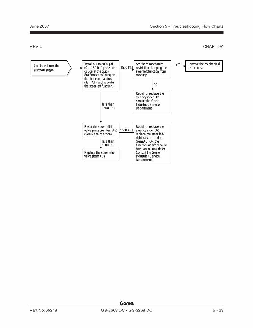
REV C
Section 5 • Troubleshooting Flow ChartsJune 2007
Part No. 65248 GS-2668 DC • GS-3268 DC 5 - 29
Continued from theprevious page.
Install a 0 to 2000 psi(0 to 150 bar) pressuregauge at the quickdisconnect coupling onthe function manifold(item AT) and activatethe steer left function.
1500 PSI
less than1500 PSI
Repair or replace thesteer cylinder ORreplace the steer left/right valve cartridge(item AC) OR thefunction manifold couldhave an internal defect.Consult the GenieIndustries ServiceDepartment.
Are there mechanicalrestrictions keeping thesteer left function frommoving?
Reset the steer reliefvalve pressure (item AE)(See Repair section).
less than1500 PSI
Remove the mechanicalrestrictions.
Repair or replace thesteer cylinder ORconsult the GenieIndustries ServiceDepartment.
yes
no
1500 PSI
Replace the steer reliefvalve (item AE).
CHART 9A

REV D
Section 5 • Troubleshooting Flow Charts June 2007
5 - 30 GS-2668 DC • GS-3268 DC Part No. 65248
Chart 10
With the key switchturned to platformcontrol and the redEmergency Stop buttonpulled out to the onposition at both theground and platformcontrols, activate thesteer rocker switch inthe right direction andcheck to see if the errorindicator light at theplatform controls is on.
light ison
light is not on
Disconnect the wiresfrom the steer right valvecoil on the functionmanifold (item Y3) andcheck the resistance ofthe valve coil. SeeRepair Section.
0V
Repair open in the wirefrom the steer right valvecoil (item Y3) to theECM U5 OR repair openin the ground wire circuitto the steer right valvecoil OR replace U5 ORconsult the GenieIndustries ServiceDepartment.
12V
0 orinfiniteohms Replace the coil (Y3).
Repair open in theground wire circuit to thevalve coil (item Y3) ORrepair or replace thesteer directional valvecartridge (item Q) ORconsult the GenieIndustries ServiceDepartment.
Install a 0 to 2000 PSI(0 to 150 bar) pressuregauge at the quickdisconnect coupling forpump #2 on the functionmanifold (item I).Activate the steer rightfunction.
1500PSI
less than 1500 PSI
Check for mechanicalrestrictions keeping thesteer right function frommoving OR repair orreplace the steercylinder OR consult theGenie Industries ServiceDepartment.
Connect the leads froma volt meter to the steerleft directional valve coil(item Y4) wire terminalswithout disconnectingthe wires. Activate thesteer rocker switch inthe left direction andcheck the voltage.
26 to 28ohms
Re-adjust the steer reliefvalve (item T) OR repairor replace the steercylinder OR replace thesteer left/right valvecartridge (item Q) ORreplace the flowregulator valve (item P)OR the function manifoldcould have an internaldefect. Consult theGenie Industries ServiceDepartment.
Steer RightFunctionInoperative(before serialnumber 41200)
Be sure all otherfunctions operatenormally.
Be sure the circuitbreaker and fuse arenot tripped or blown.
Be sure the batteriesare fully charged andproperly connected.
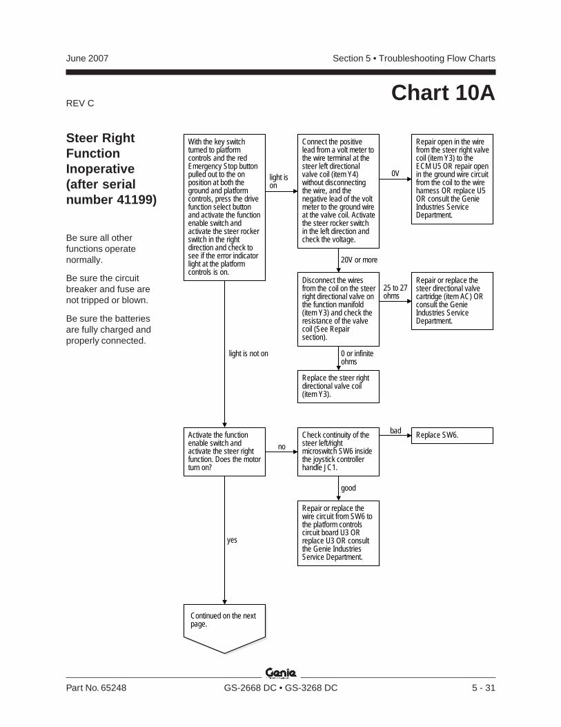
REV C
Section 5 • Troubleshooting Flow ChartsJune 2007
Part No. 65248 GS-2668 DC • GS-3268 DC 5 - 31
Chart 10A
Steer RightFunctionInoperative(after serialnumber 41199)
Be sure all otherfunctions operatenormally.
Be sure the circuitbreaker and fuse arenot tripped or blown.
Be sure the batteriesare fully charged andproperly connected.
light is not on
With the key switchturned to platformcontrols and the redEmergency Stop buttonpulled out to the onposition at both theground and platformcontrols, press the drivefunction select buttonand activate the functionenable switch andactivate the steer rockerswitch in the rightdirection and check tosee if the error indicatorlight at the platformcontrols is on.
light ison
Disconnect the wiresfrom the coil on the steerright directional valve onthe function manifold(item Y3) and check theresistance of the valvecoil (See Repairsection).
0V
Repair open in the wirefrom the steer right valvecoil (item Y3) to theECM U5 OR repair openin the ground wire circuitfrom the coil to the wireharness OR replace U5OR consult the GenieIndustries ServiceDepartment.
20V or more
25 to 27ohms
Repair or replace thesteer directional valvecartridge (item AC) ORconsult the GenieIndustries ServiceDepartment.
Activate the functionenable switch andactivate the steer rightfunction. Does the motorturn on?
Replace SW6.
yes
Continued on the nextpage.
no
badCheck continuity of thesteer left/rightmicroswitch SW6 insidethe joystick controllerhandle JC1.
good
Repair or replace thewire circuit from SW6 tothe platform controlscircuit board U3 ORreplace U3 OR consultthe Genie IndustriesService Department.
Replace the steer rightdirectional valve coil(item Y3).
Connect the positivelead from a volt meter tothe wire terminal at thesteer left directionalvalve coil (item Y4)without disconnectingthe wire, and thenegative lead of the voltmeter to the ground wireat the valve coil. Activatethe steer rocker switchin the left direction andcheck the voltage.
0 or infiniteohms
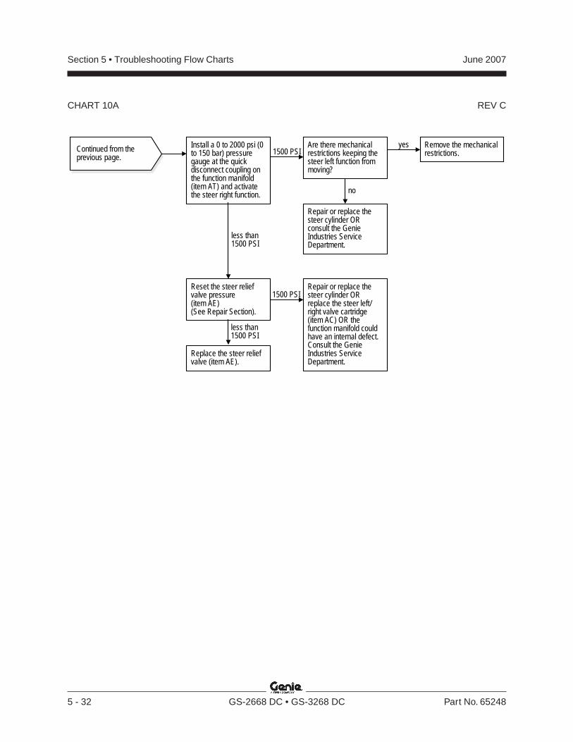
REV C
Section 5 • Troubleshooting Flow Charts June 2007
5 - 32 GS-2668 DC • GS-3268 DC Part No. 65248
CHART 10A
Continued from theprevious page.
Install a 0 to 2000 psi (0to 150 bar) pressuregauge at the quickdisconnect coupling onthe function manifold(item AT) and activatethe steer right function.
Repair or replace thesteer cylinder ORreplace the steer left/right valve cartridge(item AC) OR thefunction manifold couldhave an internal defect.Consult the GenieIndustries ServiceDepartment.
Are there mechanicalrestrictions keeping thesteer left function frommoving?
Reset the steer reliefvalve pressure(item AE)(See Repair Section).
Remove the mechanicalrestrictions.
Repair or replace thesteer cylinder ORconsult the GenieIndustries ServiceDepartment.
yes
no
Replace the steer reliefvalve (item AE).
1500 PSI
less than1500 PSI
less than1500 PSI
1500 PSI
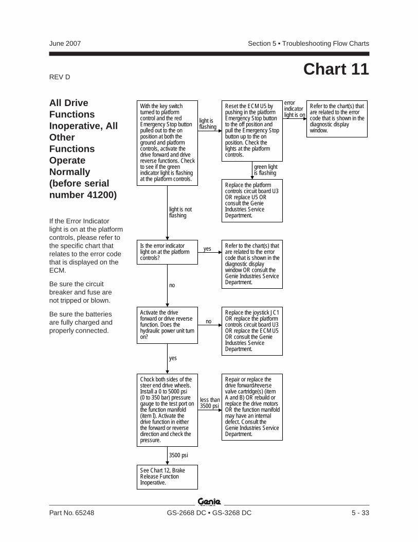
REV D
Section 5 • Troubleshooting Flow ChartsJune 2007
Part No. 65248 GS-2668 DC • GS-3268 DC 5 - 33
Chart 11
With the key switchturned to platformcontrol and the redEmergency Stop buttonpulled out to the onposition at both theground and platformcontrols, activate thedrive forward and drivereverse functions. Checkto see if the greenindicator light is flashingat the platform controls.
light isflashing
light is notflashing
Reset the ECM U5 bypushing in the platformEmergency Stop buttonto the off position andpull the Emergency Stopbutton up to the onposition. Check thelights at the platformcontrols.
Refer to the chart(s) thatare related to the errorcode that is shown in thediagnostic displaywindow.
green lightis flashing
Activate the driveforward or drive reversefunction. Does thehydraulic power unit turnon?
yes
noReplace the joystick JC1OR replace the platformcontrols circuit board U3OR replace the ECM U5OR consult the GenieIndustries ServiceDepartment.
Replace the platformcontrols circuit board U3OR replace U5 ORconsult the GenieIndustries ServiceDepartment.
errorindicatorlight is on
Is the error indicatorlight on at the platformcontrols?
yes Refer to the chart(s) thatare related to the errorcode that is shown in thediagnostic displaywindow OR consult theGenie Industries ServiceDepartment.no
Chock both sides of thesteer end drive wheels.Install a 0 to 5000 psi(0 to 350 bar) pressuregauge to the test port onthe function manifold(item I). Activate thedrive function in eitherthe forward or reversedirection and check thepressure.
less than3500 psi
See Chart 12, BrakeRelease FunctionInoperative.
3500 psi
Repair or replace thedrive forward/reversevalve cartridge(s) (itemA and B) OR rebuild orreplace the drive motorsOR the function manifoldmay have an internaldefect. Consult theGenie Industries ServiceDepartment.
All DriveFunctionsInoperative, AllOtherFunctionsOperateNormally(before serialnumber 41200)
If the Error Indicatorlight is on at the platformcontrols, please refer tothe specific chart thatrelates to the error codethat is displayed on theECM.
Be sure the circuitbreaker and fuse arenot tripped or blown.
Be sure the batteriesare fully charged andproperly connected.
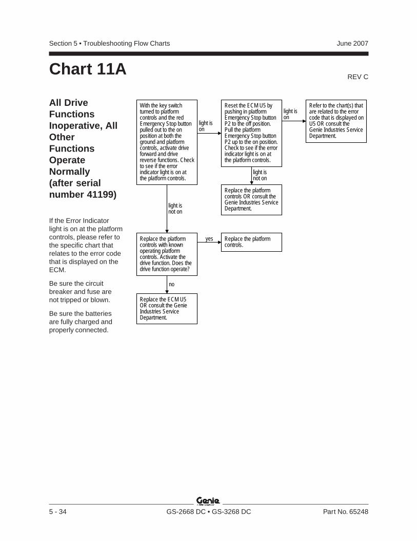
REV C
Section 5 • Troubleshooting Flow Charts June 2007
5 - 34 GS-2668 DC • GS-3268 DC Part No. 65248
With the key switchturned to platformcontrols and the redEmergency Stop buttonpulled out to the onposition at both theground and platformcontrols, activate driveforward and drivereverse functions. Checkto see if the errorindicator light is on atthe platform controls.
light ison
light isnot on
Reset the ECM U5 bypushing in platformEmergency Stop buttonP2 to the off position.Pull the platformEmergency Stop buttonP2 up to the on position.Check to see if the errorindicator light is on atthe platform controls.
Refer to the chart(s) thatare related to the errorcode that is displayed onU5 OR consult theGenie Industries ServiceDepartment.
Replace the ECM U5OR consult the GenieIndustries ServiceDepartment.
light ison
light isnot on
Replace the platformcontrols OR consult theGenie Industries ServiceDepartment.
Replace the platformcontrols with knownoperating platformcontrols. Activate thedrive function. Does thedrive function operate?
Replace the platformcontrols.
yes
no
Chart 11A
All DriveFunctionsInoperative, AllOtherFunctionsOperateNormally(after serialnumber 41199)
If the Error Indicatorlight is on at the platformcontrols, please refer tothe specific chart thatrelates to the error codethat is displayed on theECM.
Be sure the circuitbreaker and fuse arenot tripped or blown.
Be sure the batteriesare fully charged andproperly connected.
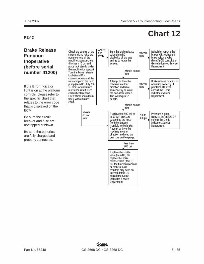
REV D
Section 5 • Troubleshooting Flow ChartsJune 2007
Part No. 65248 GS-2668 DC • GS-3268 DC 5 - 35
Chart 12
Brake ReleaseFunctionInoperative(before serialnumber 41200)
If the Error Indicatorlight is on at the platformcontrols, please refer tothe specific chart thatrelates to the error codethat is displayed on theECM.
Be sure the circuitbreaker and fuse arenot tripped or blown.
Be sure the batteriesare fully charged andproperly connected.
wheelsturnfreely
Turn the brake releasevalve (item BC)clockwise all the wayand try to rotate thewheels.
Chock the wheels at thesteer end and raise thenon-steer end of themachine approximately4 inches / 10 cm andplace jack stands underthe machine for support.Turn the brake releaseknob (item BC)counterclockwise all theway and pump the handpump (item BD) fully 13-15 times or until muchresistance is felt. Turneach wheel by hand.Each wheel should turnfreely without mucheffort.
wheelsturn
wheels do notturn
Rebuild or replace thebrakes OR replace thebrake release valve(item S) OR consult theGenie Industries ServiceDepartment.
Attempt to drive themachine in eitherdirection and havesomeone try to rotatethe non-steer wheels.This will require 2people.
wheelsturn
Brake release function isoperating correctly. Ifproblems still exist,consult the GenieIndustries ServiceDepartment.
wheels do notturn
Plumb a 0 to 500 psi (0to 50 bar) pressuregauge into the hosefrom the functionmanifold to the brake.Attempt to drive themachine in eitherdirection and read thepressure on the gauge.
200 to300 psi
Pressure is good.Replace the brakes ORconsult the GenieIndustries ServiceDepartment.
less than200 psi
Replace the shuttlevalve (item BE) ORreplace the brakerelease valve (item S)OR the function manifoldor brake releasemanifold may have aninternal defect ORconsult the GenieIndustries ServiceDepartment.
wheelsdo notturn
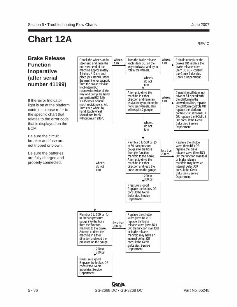
REV C
Section 5 • Troubleshooting Flow Charts June 2007
5 - 36 GS-2668 DC • GS-3268 DC Part No. 65248
Chart 12A
Brake ReleaseFunctionInoperative(after serialnumber 41199)
If the Error Indicatorlight is on at the platformcontrols, please refer tothe specific chart thatrelates to the error codethat is displayed on theECM.
Be sure the circuitbreaker and fuse arenot tripped or blown.
Be sure the batteriesare fully charged andproperly connected.
wheelsturn
Turn the brake releaseknob (item BC) all theway clockwise and try torotate the wheels.
Chock the wheels at thesteer end and raise thenon-steer end of themachine approximately4 inches / 10 cm andplace jack stands underthe machine for support.Turn the brake releaseknob (item BC)counterclockwise all theway and pump the handpump (item BD) fully13-15 times or untilmuch resistance is felt.Turn each wheel byhand. Each wheelshould turn freelywithout much effort.
wheelsturn
wheelsdo notturn
Rebuild or replace thebrakes OR replace thebrake release valve(item BC) OR consultthe Genie IndustriesService Department.
Attempt to drive themachine in eitherdirection and have anassistant try to rotate thenon-steer wheels. Thiswill require 2 people.
wheelsturn
If machine still does notdrive at full speed withthe platform in thestowed position, replacethe platform controls ORreplace the platformcontrols circuit board U3OR replace the ECM U5OR consult the GenieIndustries ServiceDepartment.
wheelsdo notturn
Plumb a 0 to 500 psi (0to 50 bar) pressuregauge into the hosefrom the functionmanifold to the brake.Attempt to drive themachine in eitherdirection and read thepressure on the gauge.
less than200 psi
Pressure is good.Replace the brakes ORconsult the GenieIndustries ServiceDepartment.
200 to300 psi
Replace the shuttlevalve (item BE) ORreplace the brakerelease valve (item BC)OR the function manifoldor brake releasemanifold may have aninternal defect ORconsult the GenieIndustries ServiceDepartment.
Plumb a 0 to 500 psi (oto 50 bar) pressuregauge into the hosefrom the functionmanifold to the brake.Attempt to drive themachine in eitherdirection and read thepressure on the gauge.
less than200 psi
Pressure is good.Replace the brakes ORconsult the GenieIndustries ServiceDepartment.
200 to300 psi
Replace the shuttlevalve (item BE) ORreplace the brakerelease valve (item BC)OR the function manifoldor brake releasemanifold may have aninternal defect ORconsult the GenieIndustries ServiceDepartment.
wheelsdo notturn
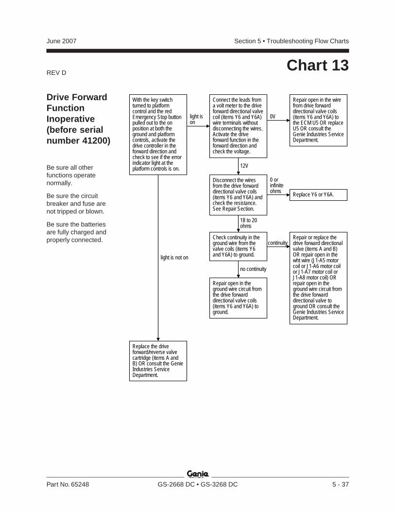
REV D
Section 5 • Troubleshooting Flow ChartsJune 2007
Part No. 65248 GS-2668 DC • GS-3268 DC 5 - 37
Chart 13
With the key switchturned to platformcontrol and the redEmergency Stop buttonpulled out to the onposition at both theground and platformcontrols, activate thedrive controller in theforward direction andcheck to see if the errorindicator light at theplatform controls is on.
light ison
light is not on
Disconnect the wiresfrom the drive forwarddirectional valve coils(items Y6 and Y6A) andcheck the resistance.See Repair Section.
0 orinfiniteohms
18 to 20ohms
Replace Y6 or Y6A.
Repair or replace thedrive forward directionalvalve (items A and B)OR repair open in thewht wire (J1-A5 motorcoil or J1-A6 motor coilor J1-A7 motor coil orJ1-A8 motor coil) ORrepair open in theground wire circuit fromthe drive forwarddirectional valve toground OR consult theGenie Industries ServiceDepartment.
Replace the driveforward/reverse valvecartridge (items A andB) OR consult the GenieIndustries ServiceDepartment.
Check continuity in theground wire from thevalve coils (items Y6and Y6A) to ground.
continuity
no continuity
Repair open in theground wire circuit fromthe drive forwarddirectional valve coils(items Y6 and Y6A) toground.
Connect the leads froma volt meter to the driveforward directional valvecoil (items Y6 and Y6A)wire terminals withoutdisconnecting the wires.Activate the driveforward function in theforward direction andcheck the voltage.
0V
Repair open in the wirefrom drive forwarddirectional valve coils(items Y6 and Y6A) tothe ECM U5 OR replaceU5 OR consult theGenie Industries ServiceDepartment.
12V
Drive ForwardFunctionInoperative(before serialnumber 41200)
Be sure all otherfunctions operatenormally.
Be sure the circuitbreaker and fuse arenot tripped or blown.
Be sure the batteriesare fully charged andproperly connected.
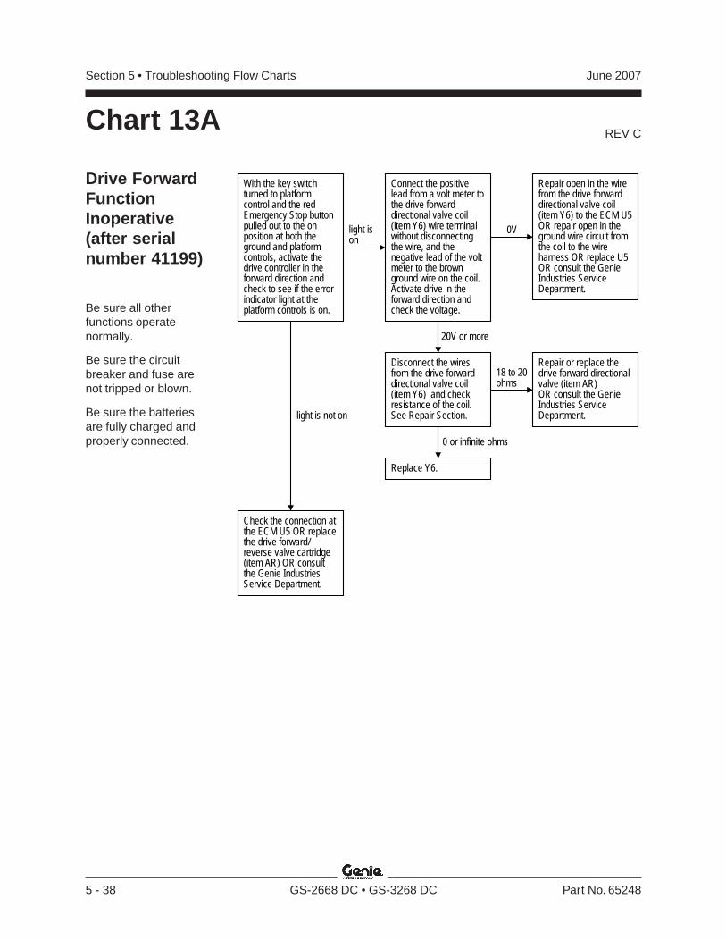
REV C
Section 5 • Troubleshooting Flow Charts June 2007
5 - 38 GS-2668 DC • GS-3268 DC Part No. 65248
Drive ForwardFunctionInoperative(after serialnumber 41199)
Be sure all otherfunctions operatenormally.
Be sure the circuitbreaker and fuse arenot tripped or blown.
Be sure the batteriesare fully charged andproperly connected.
Chart 13A
light ison
light is not on
Connect the positivelead from a volt meter tothe drive forwarddirectional valve coil(item Y6) wire terminalwithout disconnectingthe wire, and thenegative lead of the voltmeter to the brownground wire on the coil.Activate drive in theforward direction andcheck the voltage.
Disconnect the wiresfrom the drive forwarddirectional valve coil(item Y6) and checkresistance of the coil.See Repair Section.
0V
Repair open in the wirefrom the drive forwarddirectional valve coil(item Y6) to the ECM U5OR repair open in theground wire circuit fromthe coil to the wireharness OR replace U5OR consult the GenieIndustries ServiceDepartment.
20V or more
18 to 20ohms
Replace Y6.
Repair or replace thedrive forward directionalvalve (item AR)OR consult the GenieIndustries ServiceDepartment.
Check the connection atthe ECM U5 OR replacethe drive forward/reverse valve cartridge(item AR) OR consultthe Genie IndustriesService Department.
With the key switchturned to platformcontrol and the redEmergency Stop buttonpulled out to the onposition at both theground and platformcontrols, activate thedrive controller in theforward direction andcheck to see if the errorindicator light at theplatform controls is on.
0 or infinite ohms
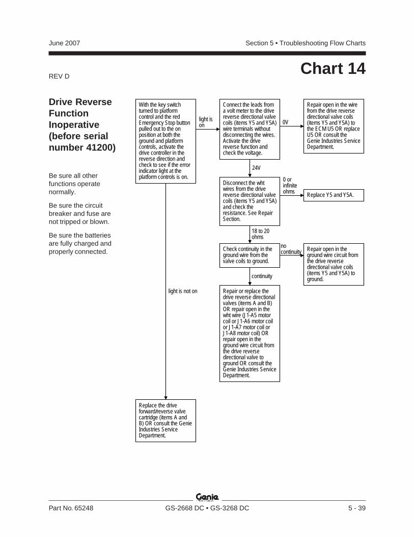
REV D
Section 5 • Troubleshooting Flow ChartsJune 2007
Part No. 65248 GS-2668 DC • GS-3268 DC 5 - 39
Chart 14
light ison
light is not on
Disconnect the whtwires from the drivereverse directional valvecoils (items Y5 and Y5A)and check theresistance. See RepairSection.
0 orinfiniteohms
18 to 20ohms
Replace Y5 and Y5A.
Repair or replace thedrive reverse directionalvalves (items A and B)OR repair open in thewht wire (J1-A5 motorcoil or J1-A6 motor coilor J1-A7 motor coil orJ1-A8 motor coil) ORrepair open in theground wire circuit fromthe drive reversedirectional valve toground OR consult theGenie Industries ServiceDepartment.
Replace the driveforward/reverse valvecartridge (items A andB) OR consult the GenieIndustries ServiceDepartment.
Check continuity in theground wire from thevalve coils to ground.
nocontinuity
continuity
Repair open in theground wire circuit fromthe drive reversedirectional valve coils(items Y5 and Y5A) toground.
Connect the leads froma volt meter to the drivereverse directional valvecoils (items Y5 and Y5A)wire terminals withoutdisconnecting the wires.Activate the drivereverse function andcheck the voltage.
0V
Repair open in the wirefrom the drive reversedirectional valve coils(items Y5 and Y5A) tothe ECM U5 OR replaceU5 OR consult theGenie Industries ServiceDepartment.
24V
With the key switchturned to platformcontrol and the redEmergency Stop buttonpulled out to the onposition at both theground and platformcontrols, activate thedrive controller in thereverse direction andcheck to see if the errorindicator light at theplatform controls is on.
Drive ReverseFunctionInoperative(before serialnumber 41200)
Be sure all otherfunctions operatenormally.
Be sure the circuitbreaker and fuse arenot tripped or blown.
Be sure the batteriesare fully charged andproperly connected.
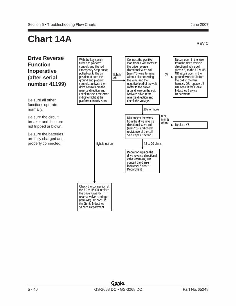
REV C
Section 5 • Troubleshooting Flow Charts June 2007
5 - 40 GS-2668 DC • GS-3268 DC Part No. 65248
Drive ReverseFunctionInoperative(after serialnumber 41199)
Be sure all otherfunctions operatenormally.
Be sure the circuitbreaker and fuse arenot tripped or blown.
Be sure the batteriesare fully charged andproperly connected.
Chart 14A
With the key switchturned to platformcontrols and the redEmergency Stop buttonpulled out to the onposition at both theground and platformcontrols, activate thedrive controller in thereverse direction andcheck to see if the errorindicator light at theplatform controls is on.
light ison
light is not on
Connect the positivelead from a volt meter tothe drive reversedirectional valve coil(item Y5) wire terminalwithout disconnectingthe wire, and thenegative lead of the voltmeter to the brownground wire on the coil.Activate drive in thereverse direction andcheck the voltage.
Disconnect the wiresfrom the drive reversedirectional valve coil(item Y5) and checkresistance of the coil.See Repair Section.
0V
Repair open in the wirefrom the drive reversedirectional valve coil(item Y5) to the ECM U5OR repair open in theground wire circuit fromthe coil to the wireharness OR replace U5OR consult the GenieIndustries ServiceDepartment.
20V or more
0 orinfiniteohms
18 to 20 ohms
Replace Y5.
Repair or replace thedrive reverse directionalvalve (item AR) ORconsult the GenieIndustries ServiceDepartment.
Check the connection atthe ECM U5 OR replacethe drive forward/reverse valve cartridge(item AR) OR consultthe Genie IndustriesService Department.
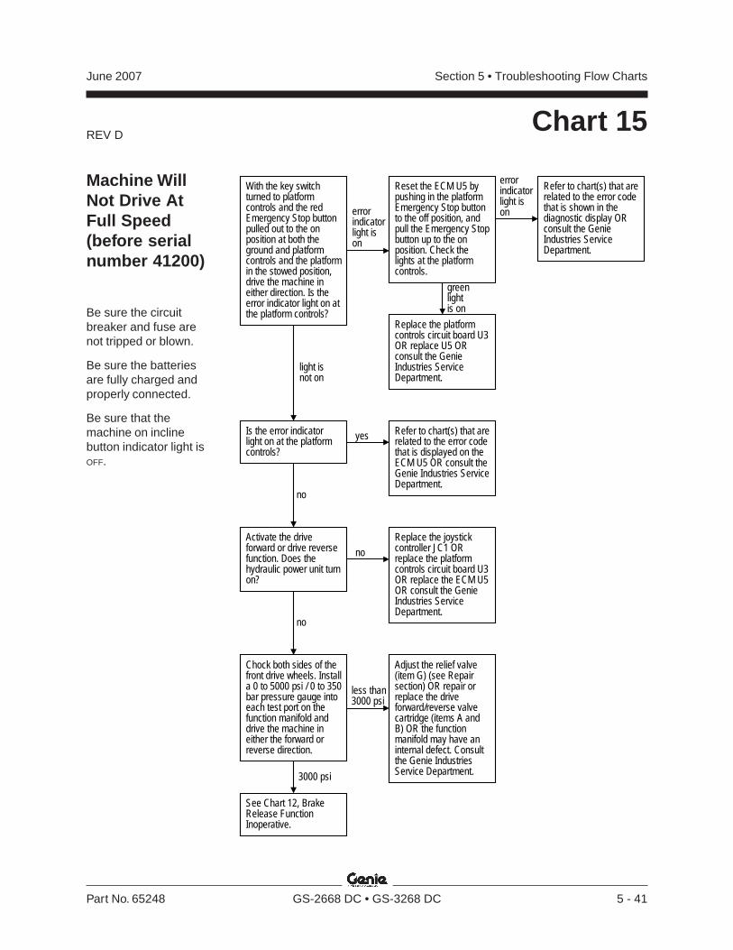
REV D
Section 5 • Troubleshooting Flow ChartsJune 2007
Part No. 65248 GS-2668 DC • GS-3268 DC 5 - 41
Chart 15
With the key switchturned to platformcontrols and the redEmergency Stop buttonpulled out to the onposition at both theground and platformcontrols and the platformin the stowed position,drive the machine ineither direction. Is theerror indicator light on atthe platform controls?
errorindicatorlight ison
light isnot on
Replace the platformcontrols circuit board U3OR replace U5 ORconsult the GenieIndustries ServiceDepartment.
greenlightis on
Reset the ECM U5 bypushing in the platformEmergency Stop buttonto the off position, andpull the Emergency Stopbutton up to the onposition. Check thelights at the platformcontrols.
Refer to chart(s) that arerelated to the error codethat is shown in thediagnostic display ORconsult the GenieIndustries ServiceDepartment.
errorindicatorlight ison
Is the error indicatorlight on at the platformcontrols?
yes Refer to chart(s) that arerelated to the error codethat is displayed on theECM U5 OR consult theGenie Industries ServiceDepartment.
no
Activate the driveforward or drive reversefunction. Does thehydraulic power unit turnon?
noReplace the joystickcontroller JC1 ORreplace the platformcontrols circuit board U3OR replace the ECM U5OR consult the GenieIndustries ServiceDepartment.
no
Adjust the relief valve(item G) (see Repairsection) OR repair orreplace the driveforward/reverse valvecartridge (items A andB) OR the functionmanifold may have aninternal defect. Consultthe Genie IndustriesService Department.
Chock both sides of thefront drive wheels. Installa 0 to 5000 psi / 0 to 350bar pressure gauge intoeach test port on thefunction manifold anddrive the machine ineither the forward orreverse direction.
less than3000 psi
3000 psi
See Chart 12, BrakeRelease FunctionInoperative.
Machine WillNot Drive AtFull Speed(before serialnumber 41200)
Be sure the circuitbreaker and fuse arenot tripped or blown.
Be sure the batteriesare fully charged andproperly connected.
Be sure that themachine on inclinebutton indicator light isOFF.
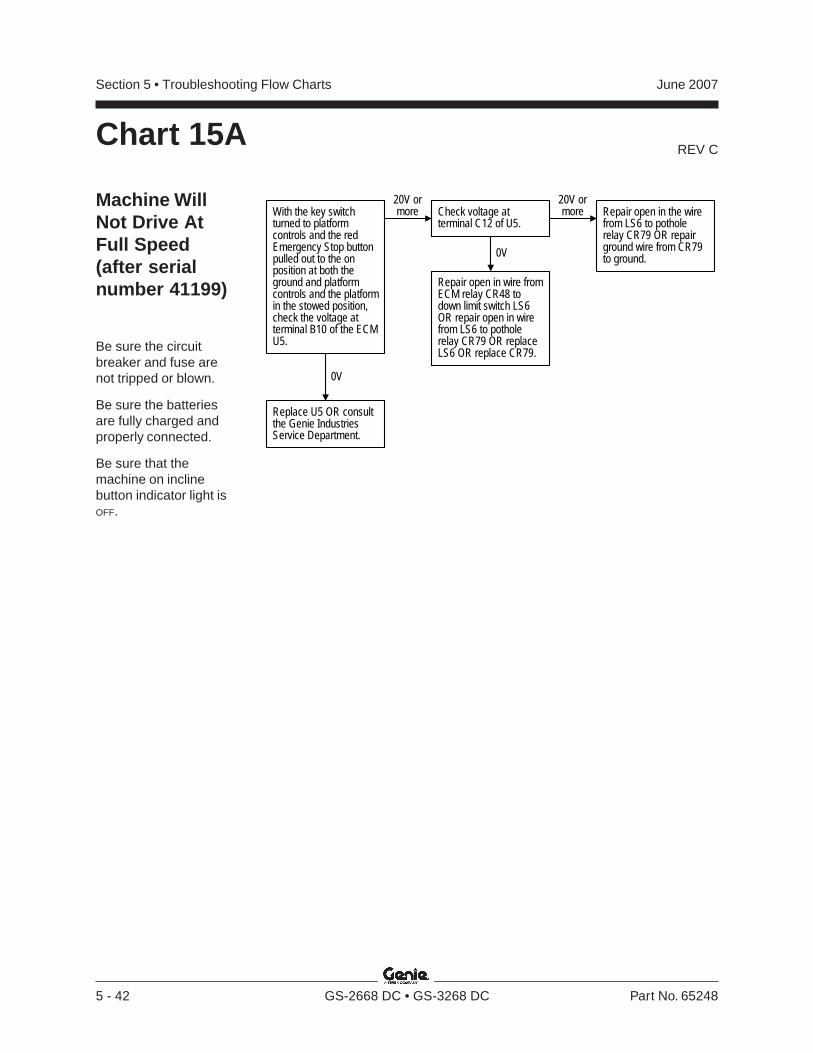
REV C
Section 5 • Troubleshooting Flow Charts June 2007
5 - 42 GS-2668 DC • GS-3268 DC Part No. 65248
Chart 15A
Machine WillNot Drive AtFull Speed(after serialnumber 41199)
Be sure the circuitbreaker and fuse arenot tripped or blown.
Be sure the batteriesare fully charged andproperly connected.
Be sure that themachine on inclinebutton indicator light isOFF.
Repair open in wire fromECM relay CR48 todown limit switch LS6OR repair open in wirefrom LS6 to potholerelay CR79 OR replaceLS6 OR replace CR79.
0V
20V ormore
Replace U5 OR consultthe Genie IndustriesService Department.
Check voltage atterminal C12 of U5.
20V ormore Repair open in the wire
from LS6 to potholerelay CR79 OR repairground wire from CR79to ground.0V
With the key switchturned to platformcontrols and the redEmergency Stop buttonpulled out to the onposition at both theground and platformcontrols and the platformin the stowed position,check the voltage atterminal B10 of the ECMU5.
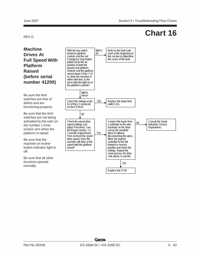
REV D
Section 5 • Troubleshooting Flow ChartsJune 2007
Part No. 65248 GS-2668 DC • GS-3268 DC 5 - 43
Chart 16
With the key switchturned to platformcontrols and the redEmergency Stop buttonpulled out to the onposition at both theground and platformcontrols and the platformraised above 6 feet / 1.8m, drive the machine ineither direction. Is theerror indicator light on atthe platform controls?
light ison
light isnot on
12V
0VConnect the leads froma voltmeter to the wireterminals on the drivecoil on the manifold(item V) withoutdisconnecting the wires.Move the joystickcontroller to the fullforward or reverseposition and check thevoltage. Repeat thesame process for drivecoils (items U and W).
Replace the ECM.
Consult the GenieIndustries ServiceDepartment.
Check the raised drivespeed settings andadjust if incorrect. Seethe Repair section, 1-2Controller Adjustments.Then recheck the raiseddrive speed. Does themachine still drive at fullspeed with the platformraised?
Yes
Check the voltage at pinA2 of the J3 connectoron the ECM U5.
0V
12V Replace the down limitswitch LS6.
Refer to the fault codechart at the beginning ofthis section to determinethe cause of the fault.
MachineDrives AtFull Speed WithPlatformRaised(before serialnumber 41200)
Be sure the limitswitches are free ofdebris and arefunctioning properly.
Be sure that the limitswitches are not beingactivated by the cam onthe number 1 innerscissor arm when theplatform is raised.
Be sure that themachine on inclinebutton indicator light isoff.
Be sure that all otherfunctions operatenormally.
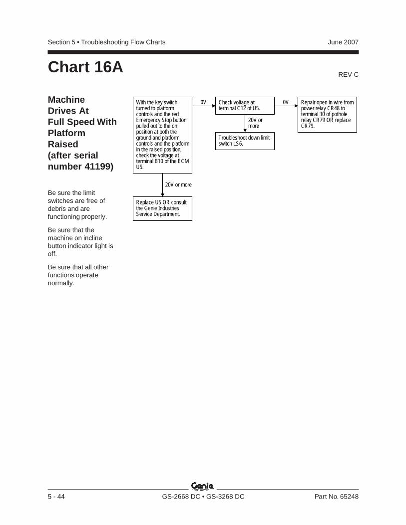
REV C
Section 5 • Troubleshooting Flow Charts June 2007
5 - 44 GS-2668 DC • GS-3268 DC Part No. 65248
Chart 16A
MachineDrives AtFull Speed WithPlatformRaised(after serialnumber 41199)
Be sure the limitswitches are free ofdebris and arefunctioning properly.
Be sure that themachine on inclinebutton indicator light isoff.
Be sure that all otherfunctions operatenormally.
Troubleshoot down limitswitch LS6.
20V or more
0V
Replace U5 OR consultthe Genie IndustriesService Department.
Check voltage atterminal C12 of U5.
0V Repair open in wire frompower relay CR48 toterminal 30 of potholerelay CR79 OR replaceCR79.
20V ormore
With the key switchturned to platformcontrols and the redEmergency Stop buttonpulled out to the onposition at both theground and platformcontrols and the platformin the raised position,check the voltage atterminal B10 of the ECMU5.
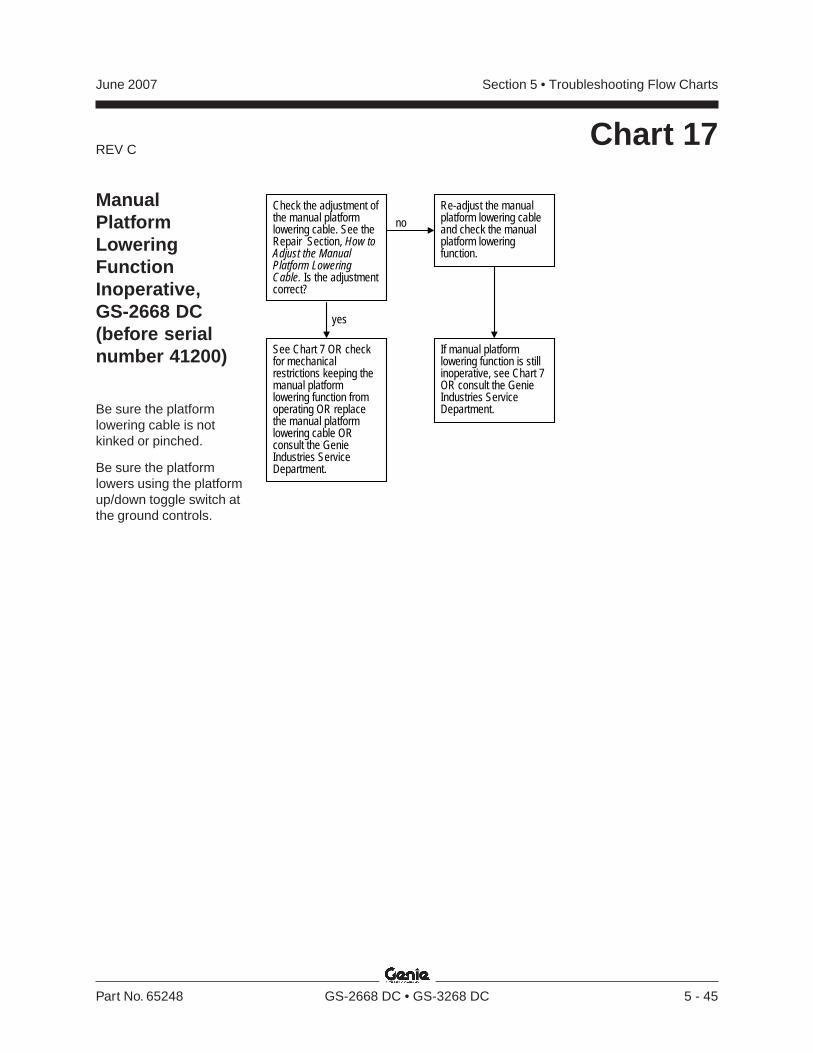
REV C
Section 5 • Troubleshooting Flow ChartsJune 2007
Part No. 65248 GS-2668 DC • GS-3268 DC 5 - 45
Chart 17
Check the adjustment ofthe manual platformlowering cable. See theRepair Section, How toAdjust the ManualPlatform LoweringCable. Is the adjustmentcorrect?
no
yes
See Chart 7 OR checkfor mechanicalrestrictions keeping themanual platformlowering function fromoperating OR replacethe manual platformlowering cable ORconsult the GenieIndustries ServiceDepartment.
Re-adjust the manualplatform lowering cableand check the manualplatform loweringfunction.
If manual platformlowering function is stillinoperative, see Chart 7OR consult the GenieIndustries ServiceDepartment.
ManualPlatformLoweringFunctionInoperative,GS-2668 DC(before serialnumber 41200)
Be sure the platformlowering cable is notkinked or pinched.
Be sure the platformlowers using the platformup/down toggle switch atthe ground controls.
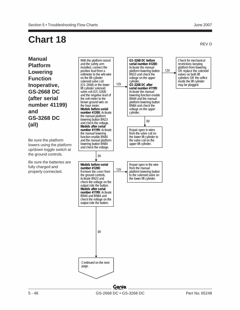
REV D
Section 5 • Troubleshooting Flow Charts June 2007
5 - 46 GS-2668 DC • GS-3268 DC Part No. 65248
With the platform raisedand the safety arminstalled, connect thepositive lead from avoltmeter to the wht wireon the lift cylindersolenoid valve coil(GS-2668) or the lowerlift cylinder solenoidvalve coil (GS-3268)and the negative lead ofthe volt meter to thebrown ground wire onthe hour meter.Models before serialnumber 41200: Activatethe manual platformlowering button BN23and check the voltage.Models after serialnumber 41199: Activatethe manual loweringfunction enable BN44and the manual platformlowering button BN84and check the voltage.
12V
0V
GS-3268 DC beforeserial number 41200:Activate the manualplatform lowering buttonBN23 and check thevoltage on the uppercylinder.GS-3268 DC afterserial number 41199:Activate the manuallowering function enableBN44 and the manualplatform lowering buttonBN84 and check thevoltage on the uppercylinder.
Repair open in wiresfrom the valve coil onthe lower lift cylinder tothe valve coil on theupper lift cylinder.
Check for mechanicalrestrictions keepingplatform from loweringOR replace the solenoidvalves on both liftcylinders OR the orificeinside the lift cylindermay be plugged.
Repair open in the wirefrom the manualplatform lowering buttonto the solenoid valve onthe lower lift cylinder.
12V
12V
0V
0V
Models before serialnumber 41200:Remove the cover fromthe ground controls.Activate BN23 andcheck the voltage on theoutput side the button.Models after serialnumber 41199: ActivateBN44 and BN84 andcheck the voltage on theoutput side the button.
Continued on the nextpage.
ManualPlatformLoweringFunctionInoperative,GS-2668 DC(after serialnumber 41199)andGS-3268 DC(all)
Be sure the platformlowers using the platformup/down toggle switch atthe ground controls.
Be sure the batteries arefully charged andproperly connected.
Chart 18
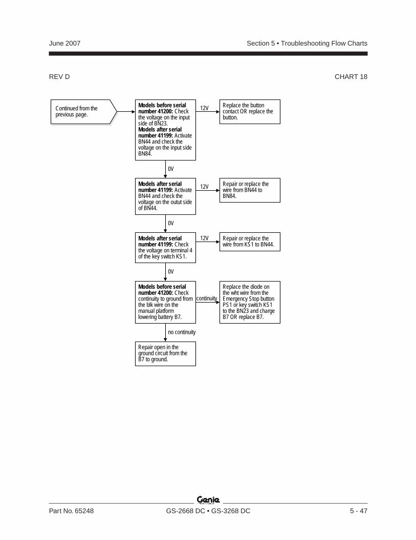
REV D
Section 5 • Troubleshooting Flow ChartsJune 2007
Part No. 65248 GS-2668 DC • GS-3268 DC 5 - 47
12V
continuity
no continuity
0V
Models before serialnumber 41200: Checkthe voltage on the inputside of BN23.Models after serialnumber 41199: ActivateBN44 and check thevoltage on the input sideBN84.
Replace the buttoncontact OR replace thebutton.
0V
Models after serialnumber 41199: ActivateBN44 and check thevoltage on the outut sideof BN44.
Repair or replace thewire from BN44 toBN84.
12V
0V
Models after serialnumber 41199: Checkthe voltage on terminal 4of the key switch KS1.
12V Repair or replace thewire from KS1 to BN44.
Models before serialnumber 41200: Checkcontinuity to ground fromthe blk wire on themanual platformlowering battery B7.
Replace the diode onthe wht wire from theEmergency Stop buttonPS1 or key switch KS1to the BN23 and chargeB7 OR replace B7.
Repair open in theground circuit from theB7 to ground.
Continued from theprevious page.
CHART 18
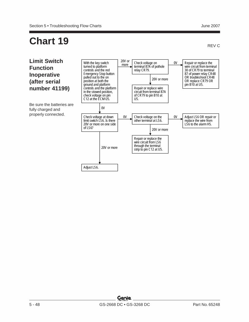
REV C
Section 5 • Troubleshooting Flow Charts June 2007
5 - 48 GS-2668 DC • GS-3268 DC Part No. 65248
Chart 19
Limit SwitchFunctionInoperative(after serialnumber 41199)
Be sure the batteries arefully charged andproperly connected.
20V ormore
0V
With the key switchturned to platformcontrols and the redEmergency Stop buttonpulled out to the onposition at both theground and platformcontrols and the platformin the stowed position,check voltage on pinC12 at the ECM U5.
20V or more
0V Check voltage on theother terminal at LS6.
0V Adjust LS6 OR repair orreplace the wire fromLS6 to the alarm H5.
20V or more
Repair or replace thewire circuit from LS6through the terminalstrip to pin C12 at U5.
Check voltage at downlimit switch LS6. Is there20V or more on one sideof LS6?
Repair or replace wirecircuit from terminal 87Aof CR79 to pin B10 atU5.
0VCheck voltage onterminal 87A of potholerelay CR79.
Repair or replace thewire circuit from terminal30 of CR79 to terminal87 of power relay CR48OR troubleshoot CR48OR replace CR79 ORpin B10 at U5.
20V or more
Adjust LS6.
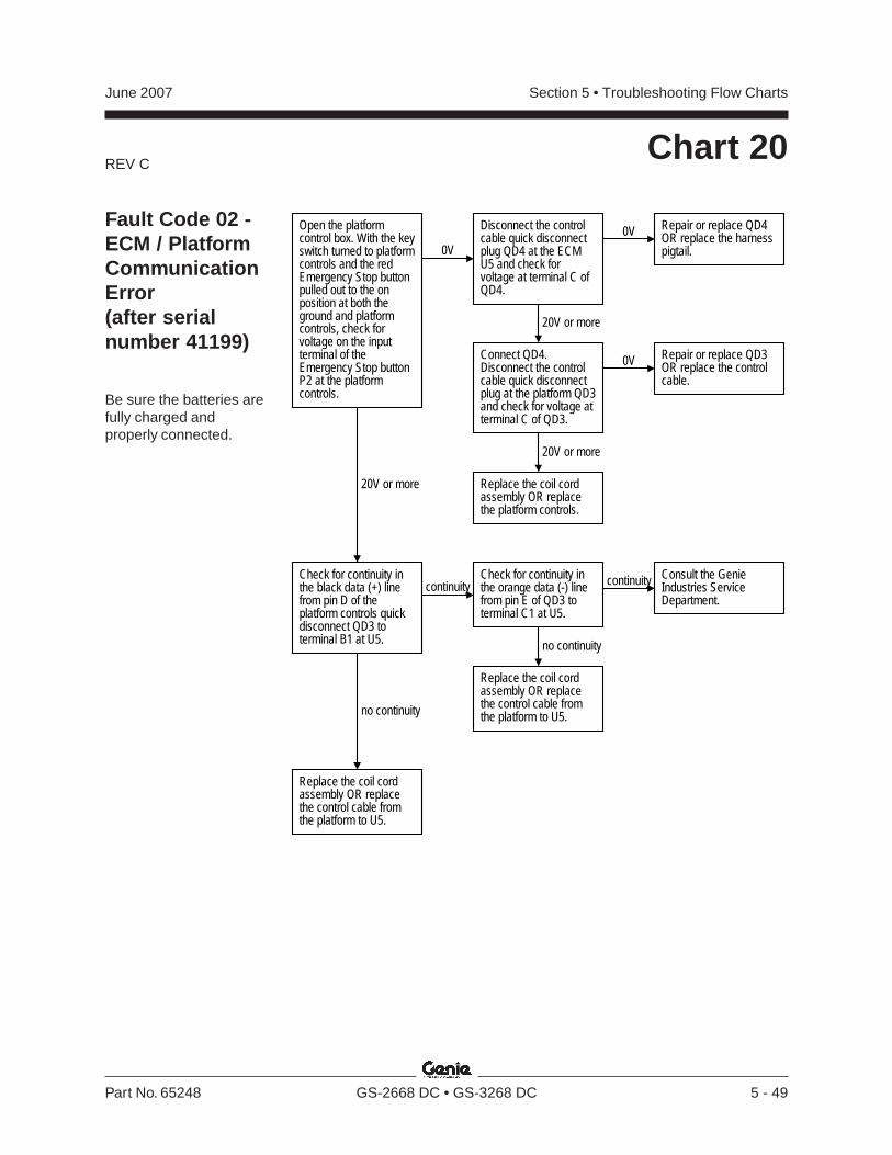
REV C
Section 5 • Troubleshooting Flow ChartsJune 2007
Part No. 65248 GS-2668 DC • GS-3268 DC 5 - 49
Chart 20
Fault Code 02 -ECM / PlatformCommunicationError(after serialnumber 41199)
Be sure the batteries arefully charged andproperly connected.
Open the platformcontrol box. With the keyswitch turned to platformcontrols and the redEmergency Stop buttonpulled out to the onposition at both theground and platformcontrols, check forvoltage on the inputterminal of theEmergency Stop buttonP2 at the platformcontrols.
0V
Disconnect the controlcable quick disconnectplug QD4 at the ECMU5 and check forvoltage at terminal C ofQD4.
20V or more
Connect QD4.Disconnect the controlcable quick disconnectplug at the platform QD3and check for voltage atterminal C of QD3.
0V Repair or replace QD4OR replace the harnesspigtail.
0V Repair or replace QD3OR replace the controlcable.
20V or more
Replace the coil cordassembly OR replacethe platform controls.
20V or more
Check for continuity inthe black data (+) linefrom pin D of theplatform controls quickdisconnect QD3 toterminal B1 at U5.
no continuity
continuity
Replace the coil cordassembly OR replacethe control cable fromthe platform to U5.
Check for continuity inthe orange data (-) linefrom pin E of QD3 toterminal C1 at U5.
continuity Consult the GenieIndustries ServiceDepartment.
no continuity
Replace the coil cordassembly OR replacethe control cable fromthe platform to U5.

REV C
Section 5 • Troubleshooting Flow Charts June 2007
5 - 50 GS-2668 DC • GS-3268 DC Part No. 65248
Chart 21
Fault Code 59 -Parallel / SeriesCoil Fault(after serialnumber 41199)
Be sure all otherfunctions operatenormally.
Be sure the circuitbreaker and fuse are nottripped or blown.
Be sure the batteries arefully charged andproperly connected.
With the key switchturned to platformcontrols and the redEmergency Stop buttonpulled out to the onposition at both theground and platformcontrols and themachine on incline LEDactivated, check forvoltage on the positiveterminal at the paralleldrive valve coil (itemY1).
0V Check for voltage at pinC8 of the ECM U5.
20V or more
Check for continuity inthe ground wire circuitfrom Y1 to ground.
nocontinuity
0 or infiniteohms
Repair or replace theground wire circuit fromY1 to ground.
Replace the paralleldrive valve (item AP)OR consult the GenieIndustries ServiceDepartment.
Disconnect the wiresfrom Y1 and checkresistance of the coil.See Repair Section.
18 to 20ohms
Replace Y1.
continuity
Replace U5.
Repair or replace thewire from pin C8 of U5to Y1 OR check the pinconnection at U5 ORreplace U5 OR consultthe Genie IndustriesService Department.
0V
20V or more
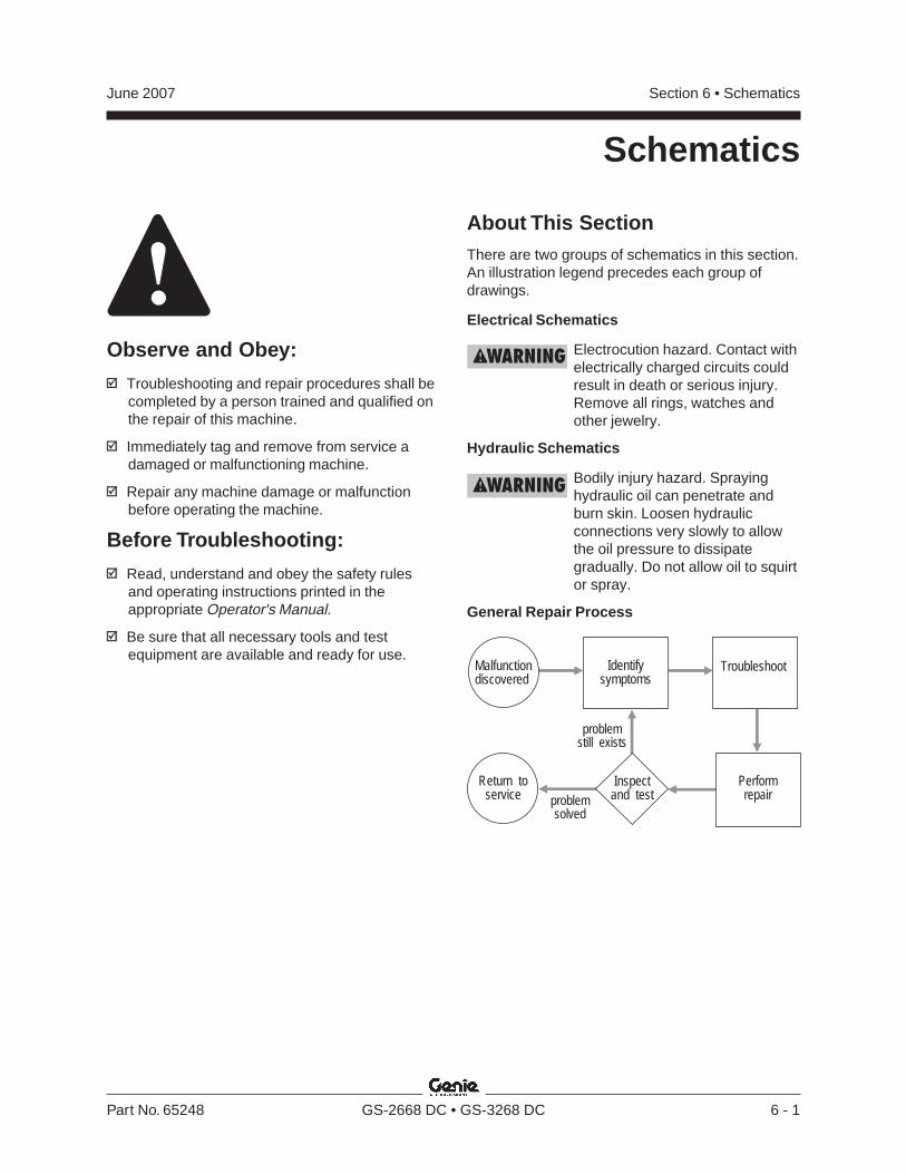
Section 6 • SchematicsJune 2007
Part No. 65248 GS-2668 DC • GS-3268 DC 6 - 1
Schematics
Observe and Obey:
Troubleshooting and repair procedures shall becompleted by a person trained and qualified onthe repair of this machine.
Immediately tag and remove from service adamaged or malfunctioning machine.
Repair any machine damage or malfunctionbefore operating the machine.
Before Troubleshooting:
Read, understand and obey the safety rulesand operating instructions printed in theappropriate Operator's Manual.
Be sure that all necessary tools and testequipment are available and ready for use.
About This SectionThere are two groups of schematics in this section.An illustration legend precedes each group ofdrawings.
Electrical Schematics
Electrocution hazard. Contact withelectrically charged circuits couldresult in death or serious injury.Remove all rings, watches andother jewelry.
Hydraulic Schematics
Bodily injury hazard. Sprayinghydraulic oil can penetrate andburn skin. Loosen hydraulicconnections very slowly to allowthe oil pressure to dissipategradually. Do not allow oil to squirtor spray.
General Repair Process
Malfunctiondiscovered
Identifysymptoms
Troubleshoot
Performrepair
Return toservice problem
solved
problemstill exists
Inspectand test
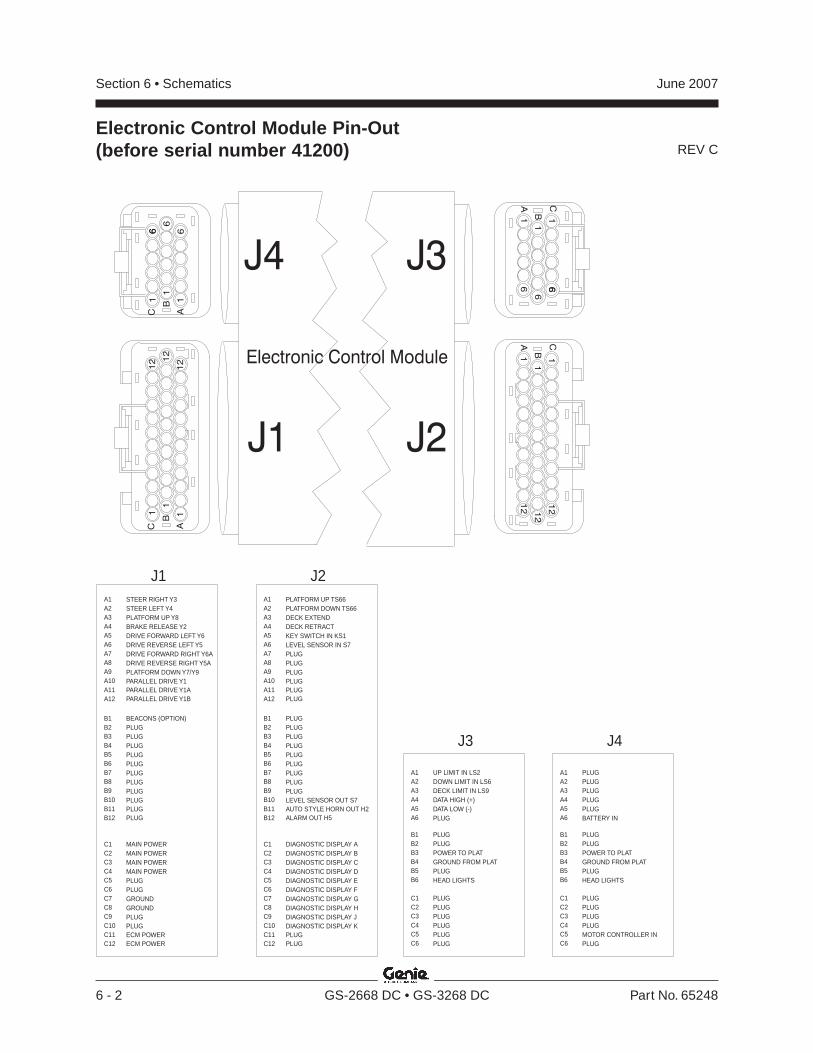
REV C
Section 6 • Schematics June 2007
6 - 2 GS-2668 DC • GS-3268 DC Part No. 65248
Electronic Control Module Pin-Out(before serial number 41200)
1A
12
B
C
1
1
12
12
1A
12
B
C
1
1
12
12
C
1A
B1
1
6
6
66
C
1A
B1
1
6
6
6 6J4 J3
J2J1
Electronic Control Module
STEER RIGHT Y3
BEACONS (OPTION)
MAIN POWER
STEER LEFT Y4
PLUG
MAIN POWER
PLATFORM UP Y8
PLUG
MAIN POWER
BRAKE RELEASE Y2
PLUG
MAIN POWER
DRIVE FORWARD LEFT Y6
PLUG
PLUG
DRIVE REVERSE LEFT Y5
PLUG
PLUG
DRIVE FORWARD RIGHT Y6A
PLUG
GROUND
DRIVE REVERSE RIGHT Y5A
PLUG
GROUND
PLATFORM DOWN Y7/Y9
PLUG
PLUG
PARALLEL DRIVE Y1
PLUG
PLUG
PARALLEL DRIVE Y1A
PLUG
ECM POWER
PARALLEL DRIVE Y1B
PLUG
ECM POWER
A1
J1
B1
C1
A2
B2
C2
A3
B3
C3
A4
B4
C4
A5
B5
C5
A6
B6
C6
A7
B7
C7
A8
B8
C8
A9
B9
C9
A10
B10
C10
A11
B11
C11
A12
B12
C12
PLATFORM UP TS66
PLUG
DIAGNOSTIC DISPLAY A
PLATFORM DOWN TS66
PLUG
DIAGNOSTIC DISPLAY B
DECK EXTEND
PLUG
DIAGNOSTIC DISPLAY C
DECK RETRACT
PLUG
DIAGNOSTIC DISPLAY D
KEY SWITCH IN KS1
PLUG
DIAGNOSTIC DISPLAY E
LEVEL SENSOR IN S7
PLUG
DIAGNOSTIC DISPLAY F
PLUG
PLUG
DIAGNOSTIC DISPLAY G
PLUG
PLUG
DIAGNOSTIC DISPLAY H
PLUG
PLUG
DIAGNOSTIC DISPLAY J
PLUG
LEVEL SENSOR OUT S7
DIAGNOSTIC DISPLAY K
PLUG
AUTO STYLE HORN OUT H2
PLUG
PLUG
ALARM OUT H5
PLUG
A1
J2
B1
C1
A2
B2
C2
A3
B3
C3
A4
B4
C4
A5
B5
C5
A6
B6
C6
A7
B7
C7
A8
B8
C8
A9
B9
C9
A10
B10
C10
A11
B11
C11
A12
B12
C12
UP LIMIT IN LS2DOWN LIMIT IN LS6DECK LIMIT IN LS9DATA HIGH (+)DATA LOW (-)PLUG
A1
J3
A2A3A4A5A6
PLUGPLUGPOWER TO PLATGROUND FROM PLATPLUGHEAD LIGHTS
B1B2B3B4B5B6
PLUGPLUGPLUGPLUGPLUGPLUG
C1C2C3C4C5C6
PLUGPLUGPLUGPLUGPLUGBATTERY IN
A1
J4
A2A3A4A5A6
PLUGPLUGPOWER TO PLATGROUND FROM PLATPLUGHEAD LIGHTS
B1B2B3B4B5B6
PLUGPLUGPLUGPLUGMOTOR CONTROLLER INPLUG
C1C2C3C4C5C6
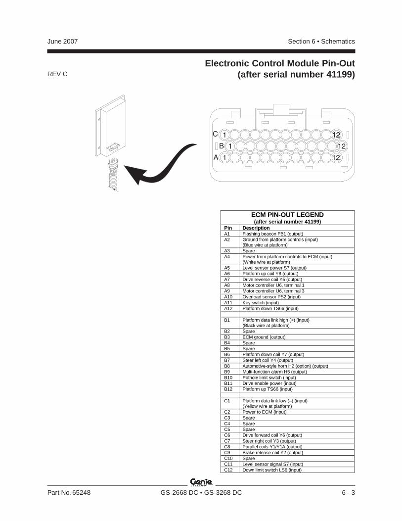
REV C
Section 6 • SchematicsJune 2007
Part No. 65248 GS-2668 DC • GS-3268 DC 6 - 3
Electronic Control Module Pin-Out(after serial number 41199)
ECM PIN-OUT LEGEND(after serial number 41199)
Pin DescriptionA1 Flashing beacon FB1 (output)A2 Ground from platform controls (input)
(Blue wire at platform)A3 SpareA4 Power from platform controls to ECM (input)
(White wire at platform)A5 Level sensor power S7 (output)A6 Platform up coil Y8 (output)A7 Drive reverse coil Y5 (output)A8 Motor controller U6, terminal 1A9 Motor controller U6, terminal 3A10 Overload sensor PS2 (input)A11 Key switch (input)A12 Platform down TS66 (input)
B1 Platform data link high (+) (input)(Black wire at platform)
B2 SpareB3 ECM ground (output)B4 SpareB5 SpareB6 Platform down coil Y7 (output)B7 Steer left coil Y4 (output)B8 Automotive-style horn H2 (option) (output)B9 Multi-function alarm H5 (output)B10 Pothole limit switch (input)B11 Drive enable power (input)B12 Platform up TS66 (input)
C1 Platform data link low (–) (input)(Yellow wire at platform)
C2 Power to ECM (input)C3 SpareC4 SpareC5 SpareC6 Drive forward coil Y6 (output)C7 Steer right coil Y3 (output)C8 Parallel coils Y1/Y1A (output)C9 Brake release coil Y2 (output)C10 SpareC11 Level sensor signal S7 (input)C12 Down limit switch LS6 (input)
A 12
B
C
1
1
1
12
1212

REV D
Section 6 • Schematics June 2007
6 - 4 GS-2668 DC • GS-3268 DC Part No. 65248
Platform Controls Wiring Diagram(before serial number 41200)
P2EMERGENCY STOP
BUTTON
JC1JOYSTICK
CONTROLLER
U3PLATFORMCONTROLS
CIRCUITBOARD
BK
RD
RD
BK
WH
BL
YL
H1ALARM
TOCOILCORDASSEMBLY
BN13FUNCTIONENABLE/LOW SPEEDBUTTON
BN12FUNCTION
ENABLE/HIGH SPEED
BUTTON
TS20PLATFORMUP/DOWNTOGGLESWITCH
2 1N
C
BK
RD
YL
SW25DIP SWITCH
WH
BN
WH/BK
WH/RD
WH/BL
OR
PP
BKBLRD WHBK
BK
ABBREVIATION LEGENDItem Description
ButtonBNBN12 = High speed lift enableBN13 = Low speed lift enable
D7 Voltage regulatorH1 AlarmJC1 Joystick controllerP2 Emergency Stop button at platform controlsSW25 DIP switchTS20 Platform up/down toggle switchU3 Printed circuit board
WIRE COLOR LEGEND
Color Description BL Blue BK Black BN Brown OR Orange PP Purple RD Red WH White
WH/BK White / Black WH/BL White / Blue WH/RD White / Red
YL Yellow
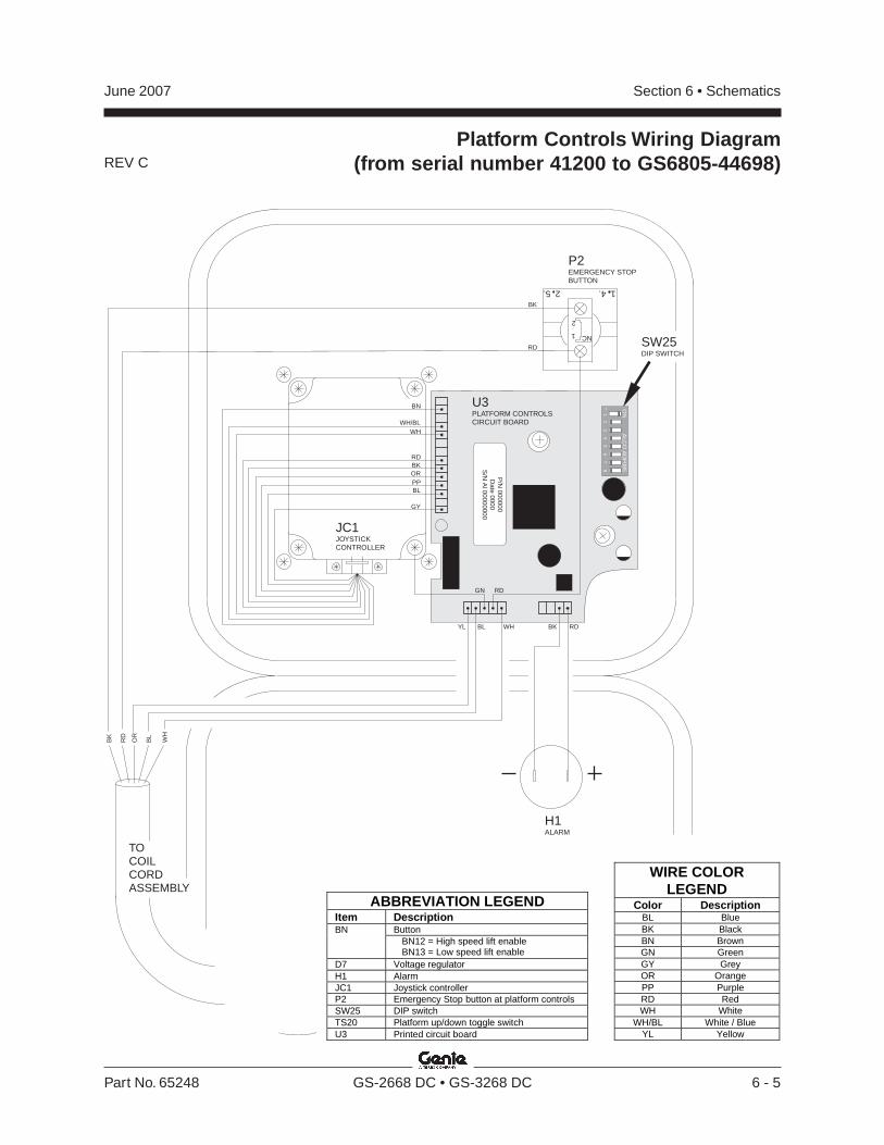
REV C
Section 6 • SchematicsJune 2007
Part No. 65248 GS-2668 DC • GS-3268 DC 6 - 5
P2EMERGENCY STOPBUTTON
H1ALARM
BL
WH
OR
RD
BK
TOCOILCORDASSEMBLY
RD
RD
BK
SW25DIP SWITCH
U3PLATFORM CONTROLSCIRCUIT BOARD
1 4.2 5.
2
1 NC
19F
23
45
67
8
ON
ALC
O A
DF
085
P/N
000000D
ate 0000S
/N A
l 00000000
GN
YL BL BKWH RD
JC1JOYSTICKCONTROLLER
RDBKOR
WHWH/BL
PPBL
GY
BN
Platform Controls Wiring Diagram(from serial number 41200 to GS6805-44698)
ABBREVIATION LEGEND Item Description
Button BN BN12 = High speed lift enable BN13 = Low speed lift enable
D7 Voltage regulator H1 Alarm JC1 Joystick controller P2 Emergency Stop button at platform controls SW25 DIP switch TS20 Platform up/down toggle switch U3 Printed circuit board
WIRE COLOR LEGEND
Color Description BL Blue BK Black BN Brown GN Green GY Grey OR Orange PP Purple RD Red WH White
WH/BL White / Blue YL Yellow
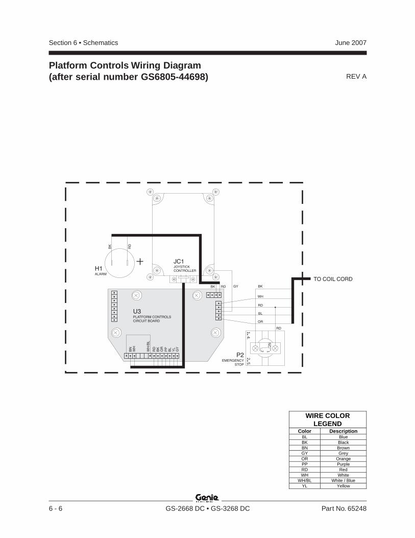
REV A
Section 6 • Schematics June 2007
6 - 6 GS-2668 DC • GS-3268 DC Part No. 65248
Platform Controls Wiring Diagram(after serial number GS6805-44698)
H1ALARM
RD
BK
1 4.2 5.
2 1N
C
P2EMERGENCY
STOP
JC1JOYSTICK
CONTROLLER
RD
BK
OR
WH
WH
/BL
PP
BL
GY
BN
YL
GY
WH
RD
BL
OR
TO COIL CORD
RD
BK
RDBK
U3PLATFORM CONTROLS
CIRCUIT BOARD
WIRE COLOR LEGEND
Color Description BL Blue BK Black BN Brown GY Grey OR Orange PP Purple RD Red WH White
WH/BL White / Blue YL Yellow
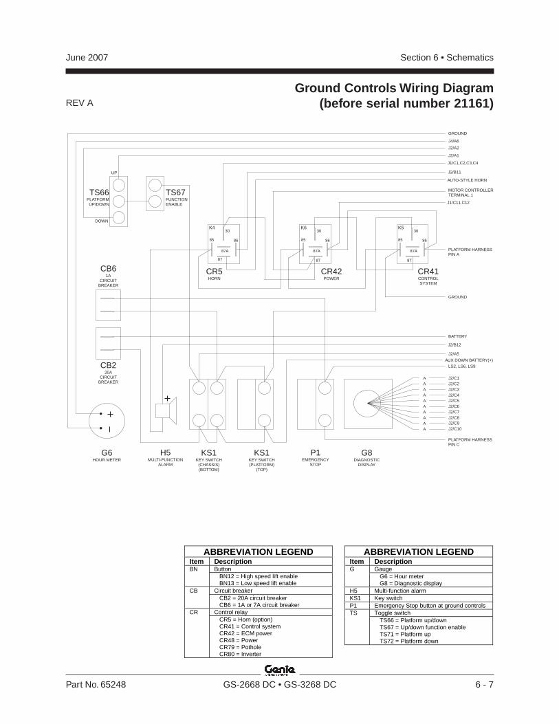
REV A
Section 6 • SchematicsJune 2007
Part No. 65248 GS-2668 DC • GS-3268 DC 6 - 7
P1EMERGENCY
STOP
G8DIAGNOSTIC
DISPLAY
G6HOUR METER
CB220A
CIRCUITBREAKER
CB61A
CIRCUITBREAKER
KS1KEY SWITCH
(CHASSIS)(BOTTOM)
KS1KEY SWITCH(PLATFORM)
(TOP)
CR41CONTROLSYSTEM
CR42POWER
CR5HORN
TS66PLATFORMUP/DOWN
TS67FUNCTIONENABLE
J2/B12
J2/A1
J2/A2
J4/A6
GROUND
J2/A5
AUTO-STYLE HORN
J1/C1,C2,C3,C4
J2/B11
J1/C11,C12
UP
DOWN
MOTOR CONTROLLERTERMINAL 1
LS2, LS6, LS9
GROUND
BATTERY
K530
87A
87
8685
K630
87A
87
8685
K430
87A
87
8685
J2/C1A
A
A
A
A
A
A
A
A
A
J2/C5
J2/C2
J2/C6
J2/C3
J2/C7
J2/C4
J2/C8J2/C9J2/C10
H5MULTI-FUNCTION
ALARM
PLATFORM HARNESSPIN C
PLATFORM HARNESSPIN A
AUX DOWN BATTERY(+)
ABBREVIATION LEGENDItem Description
ButtonBNBN12 = High speed lift enableBN13 = Low speed lift enable
Circuit breakerCBCB2 = 20A circuit breakerCB6 = 1A or 7A circuit breaker
Control relayCRCR5 = Horn (option)CR41 = Control systemCR42 = ECM powerCR48 = PowerCR79 = PotholeCR80 = Inverter
ABBREVIATION LEGENDItem Description
GaugeGG6 = Hour meterG8 = Diagnostic display
H5 Multi-function alarmKS1 Key switchP1 Emergency Stop button at ground controls
Toggle switchTSTS66 = Platform up/downTS67 = Up/down function enableTS71 = Platform upTS72 = Platform down
Ground Controls Wiring Diagram(before serial number 21161)
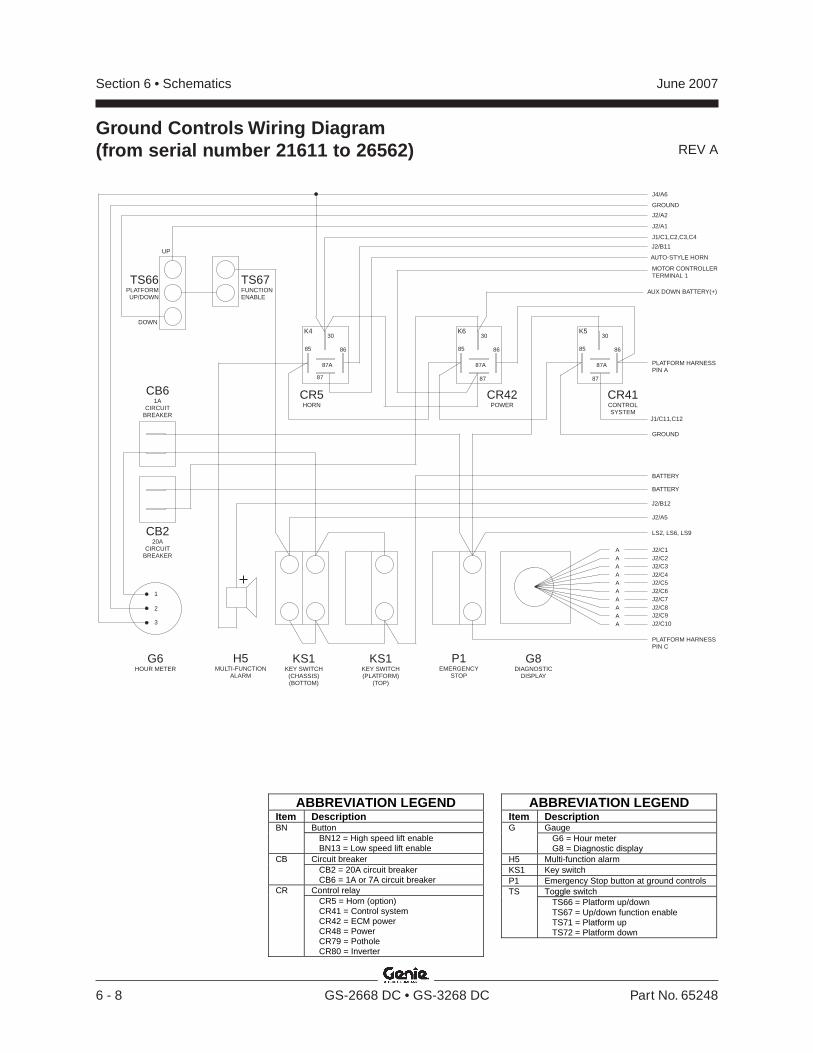
REV A
Section 6 • Schematics June 2007
6 - 8 GS-2668 DC • GS-3268 DC Part No. 65248
Ground Controls Wiring Diagram(from serial number 21611 to 26562)
P1EMERGENCY
STOP
G8DIAGNOSTIC
DISPLAY
G6HOUR METER
CB220A
CIRCUITBREAKER
1
2
3
CB61A
CIRCUITBREAKER
KS1KEY SWITCH
(CHASSIS)(BOTTOM)
KS1KEY SWITCH(PLATFORM)
(TOP)
CR41CONTROLSYSTEM
CR42POWER
CR5HORN
TS66PLATFORMUP/DOWN
TS67FUNCTIONENABLE
J2/B12
J2/A1
J2/A2
J2/A5
AUTO-STYLE HORN
J1/C1,C2,C3,C4
J2/B11
J1/C11,C12
UP
DOWN
PLATFORM HARNESSPIN C
PLATFORM HARNESSPIN A
MOTOR CONTROLLERTERMINAL 1
LS2, LS6, LS9
GROUND
BATTERY
BATTERY
K530
87A
87
8685
K630
87A
87
8685
K430
87A
87
8685
J2/C1A
A
A
A
A
A
A
A
A
A
J2/C5
J2/C2
J2/C6
J2/C3
J2/C7
J2/C4
J2/C8J2/C9J2/C10
H5MULTI-FUNCTION
ALARM
J4/A6
GROUND
AUX DOWN BATTERY(+)
ABBREVIATION LEGENDItem Description
ButtonBNBN12 = High speed lift enableBN13 = Low speed lift enable
Circuit breakerCBCB2 = 20A circuit breakerCB6 = 1A or 7A circuit breaker
Control relayCRCR5 = Horn (option)CR41 = Control systemCR42 = ECM powerCR48 = PowerCR79 = PotholeCR80 = Inverter
ABBREVIATION LEGENDItem Description
GaugeGG6 = Hour meterG8 = Diagnostic display
H5 Multi-function alarmKS1 Key switchP1 Emergency Stop button at ground controls
Toggle switchTSTS66 = Platform up/downTS67 = Up/down function enableTS71 = Platform upTS72 = Platform down

REV A
Section 6 • SchematicsJune 2007
Part No. 65248 GS-2668 DC • GS-3268 DC 6 - 9
P1EMERGENCY
STOP
G8DIAGNOSTIC
DISPLAY
G6HOUR METER
CB220A
CIRCUITBREAKER
1
2
3
CB61A
CIRCUITBREAKER
KS1KEY SWITCH
(CHASSIS)(BOTTOM)
KS1KEY SWITCH(PLATFORM)
(TOP)
CR41CONTROLSYSTEM
CR42POWER
CR5HORN
TS66PLATFORMUP/DOWN
TS67FUNCTIONENABLE
J2/B12
J2/A1
J2/A2
J2/B9
GROUND
J2/A5
AUTO-STYLE HORN
PLAT OVERLOAD (+)(OPTION)
J1/C1,C2,C3,C4
J2/B11
J1/C11,C12
UP
DOWN
PLATFORM HARNESSPIN C
PLATFORM HARNESSPIN A
MOTOR CONTROLLERTERMINAL 1
LS6 ANDLS9 (3268) OR J3/A3 (2668) ANDLS2 (3268) OR J3/A1(2668)
GROUND
BATTERY
K530
87A
87
8685
K630
87A
87
8685
K430
87A
87
8685
J2/C1A
A
A
A
A
A
A
A
A
A
J2/C5
J2/C2
J2/C6
J2/C3
J2/C7
J2/C4
J2/C8J2/C9J2/C10
H5MULTI-FUNCTION
ALARM
BATTERY
AUX DOWN BATTERY(+)
ABBREVIATION LEGENDItem Description
ButtonBNBN12 = High speed lift enableBN13 = Low speed lift enable
Circuit breakerCBCB2 = 20A circuit breakerCB6 = 1A or 7A circuit breaker
Control relayCRCR5 = Horn (option)CR41 = Control systemCR42 = ECM powerCR48 = PowerCR79 = PotholeCR80 = Inverter
ABBREVIATION LEGENDItem Description
GaugeGG6 = Hour meterG8 = Diagnostic display
H5 Multi-function alarmKS1 Key switchP1 Emergency Stop button at ground controls
Toggle switchTSTS66 = Platform up/downTS67 = Up/down function enableTS71 = Platform upTS72 = Platform down
Ground Controls Wiring Diagram(from serial number 26563 to 33850)
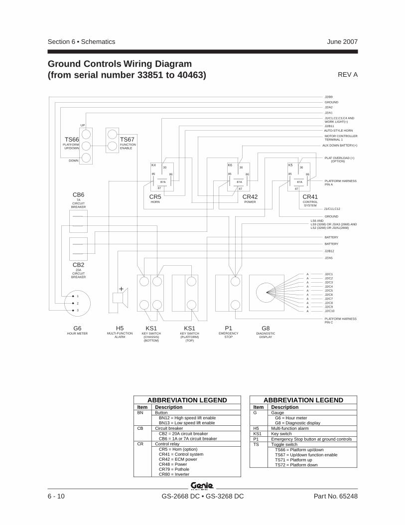
REV A
Section 6 • Schematics June 2007
6 - 10 GS-2668 DC • GS-3268 DC Part No. 65248
Ground Controls Wiring Diagram(from serial number 33851 to 40463)
P1EMERGENCY
STOP
G8DIAGNOSTIC
DISPLAY
G6HOUR METER
CB220A
CIRCUITBREAKER
1
2
3
CB67A
CIRCUITBREAKER
KS1KEY SWITCH
(CHASSIS)(BOTTOM)
KS1KEY SWITCH(PLATFORM)
(TOP)
CR41CONTROLSYSTEM
CR42POWER
CR5HORN
TS66PLATFORMUP/DOWN
TS67FUNCTIONENABLE
J2/B12
J2/A1
J2/A2
J2/B9
GROUND
J2/A5
AUTO-STYLE HORN
PLAT OVERLOAD (+)(OPTION)
J1/C1,C2,C3,C4 ANDWORK LIGHT(+)J2/B11
J1/C11,C12
UP
DOWN
PLATFORM HARNESSPIN C
PLATFORM HARNESSPIN A
MOTOR CONTROLLERTERMINAL 1
LS6 ANDLS9 (3268) OR J3/A3 (2668) ANDLS2 (3268) OR J3/A1(2668)
GROUND
BATTERY
K530
87A
87
8685
K630
87A
87
8685
K430
87A
87
8685
J2/C1A
A
A
A
A
A
A
A
A
A
J2/C5
J2/C2
J2/C6
J2/C3
J2/C7
J2/C4
J2/C8J2/C9J2/C10
H5MULTI-FUNCTION
ALARM
BATTERY
AUX DOWN BATTERY(+)
ABBREVIATION LEGENDItem Description
ButtonBNBN12 = High speed lift enableBN13 = Low speed lift enable
Circuit breakerCBCB2 = 20A circuit breakerCB6 = 1A or 7A circuit breaker
Control relayCRCR5 = Horn (option)CR41 = Control systemCR42 = ECM powerCR48 = PowerCR79 = PotholeCR80 = Inverter
ABBREVIATION LEGENDItem Description
GaugeGG6 = Hour meterG8 = Diagnostic display
H5 Multi-function alarmKS1 Key switchP1 Emergency Stop button at ground controls
Toggle switchTSTS66 = Platform up/downTS67 = Up/down function enableTS71 = Platform upTS72 = Platform down

REV A
Section 6 • SchematicsJune 2007
Part No. 65248 GS-2668 DC • GS-3268 DC 6 - 11
P1EMERGENCY
STOP
G8DIAGNOSTIC
DISPLAY
G6HOUR METER
CB220A
CIRCUITBREAKER
1
2
3
CB67A
CIRCUITBREAKER
KS1KEY SWITCH
(CHASSIS)(BOTTOM)
KS1KEY SWITCH(PLATFORM)
(TOP)
CR41CONTROLSYSTEM
CR42POWER
CR5HORN
TS66PLATFORMUP/DOWN
TS67FUNCTIONENABLE
J2/B12
J2/A1
J2/A2
J2/B9
GROUND
J2/A5
AUTO-STYLE HORN
PLAT OVERLOAD (+)(OPTION)
J1/C1,C2,C3,C4 ANDWORK LIGHT(+)
J2/B11
J1/C11,C12
UP
DOWN
PLATFORM HARNESSPIN C
PLATFORM HARNESSPIN A
MOTOR CONTROLLERTERMINAL 1
LS6 ANDLS9 (3268) OR J3/A3 (2668) ANDLS2 (3268) OR J3/A1(2668)
GROUND
BATTERY
K530
87A
87
8685
K630
87A
87
8685
K430
87A
87
8685
J2/C1A
A
A
A
A
A
A
A
A
A
J2/C5
J2/C2
J2/C6
J2/C3
J2/C7
J2/C4
J2/C8J2/C9J2/C10
H5MULTI-FUNCTION
ALARM
AUX DOWN BATTERY(+)
ABBREVIATION LEGENDItem Description
ButtonBNBN12 = High speed lift enableBN13 = Low speed lift enable
Circuit breakerCBCB2 = 20A circuit breakerCB6 = 1A or 7A circuit breaker
Control relayCRCR5 = Horn (option)CR41 = Control systemCR42 = ECM powerCR48 = PowerCR79 = PotholeCR80 = Inverter
ABBREVIATION LEGENDItem Description
GaugeGG6 = Hour meterG8 = Diagnostic display
H5 Multi-function alarmKS1 Key switchP1 Emergency Stop button at ground controls
Toggle switchTSTS66 = Platform up/downTS67 = Up/down function enableTS71 = Platform upTS72 = Platform down
Ground Controls Wiring Diagram(from serial number 40464 to 40751)
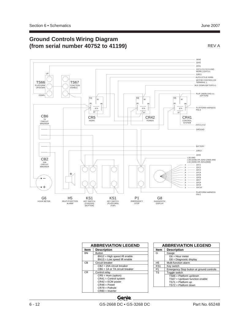
REV A
Section 6 • Schematics June 2007
6 - 12 GS-2668 DC • GS-3268 DC Part No. 65248
Ground Controls Wiring Diagram(from serial number 40752 to 41199)
P1EMERGENCY
STOP
G8DIAGNOSTIC
DISPLAY
G6HOUR METER
CB220A
CIRCUITBREAKER
CB67A
CIRCUITBREAKER
KS1KEY SWITCH
(CHASSIS)(BOTTOM)
KS1KEY SWITCH(PLATFORM)
(TOP)
CR41CONTROLSYSTEM
CR42POWER
CR5HORN
TS66PLATFORMUP/DOWN
TS67FUNCTIONENABLE
J2/B12
J2/A1
J2/A2
J4/A6
J2/A5
AUTO-STYLE HORN
PLAT OVERLOAD (+)(OPTION)
J1/C1,C2,C3,C4 ANDWORK LIGHT(+)
J2/B11
AUX DOWN BATTERY(+)
J1/C11,C12
UP
DOWN
PLATFORM HARNESSPIN C
PLATFORM HARNESSPIN A
MOTOR CONTROLLERTERMINAL 1
LS6 ANDLS9 (3268) OR J3/A3 (2668) ANDLS2 (3268) OR J3/A1(2668)
GROUND
BATTERY
K530
87A
87
8685
K630
87A
87
8685
K430
87A
87
8685
J2/C1A
A
A
A
A
A
A
A
A
A
J2/C5
J2/C2
J2/C6
J2/C3
J2/C7
J2/C4
J2/C8J2/C9J2/C10
H5MULTI-FUNCTION
ALARM
ABBREVIATION LEGENDItem Description
ButtonBNBN12 = High speed lift enableBN13 = Low speed lift enable
Circuit breakerCBCB2 = 20A circuit breakerCB6 = 1A or 7A circuit breaker
Control relayCRCR5 = Horn (option)CR41 = Control systemCR42 = ECM powerCR48 = PowerCR79 = PotholeCR80 = Inverter
ABBREVIATION LEGENDItem Description
GaugeGG6 = Hour meterG8 = Diagnostic display
H5 Multi-function alarmKS1 Key switchP1 Emergency Stop button at ground controls
Toggle switchTSTS66 = Platform up/downTS67 = Up/down function enableTS71 = Platform upTS72 = Platform down
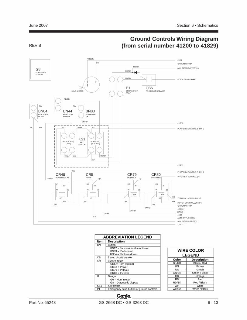
REV B
Section 6 • SchematicsJune 2007
Part No. 65248 GS-2668 DC • GS-3268 DC 6 - 13
Ground Controls Wiring Diagram(from serial number 41200 to 41829)
P1EMERGENCYSTOP
G6HOUR METER
CB67A CIRCUIT BREAKER
GN/BK
WH
WH WH
RD/BK
RD/BK
WH/BK
GN/BK
BN
BK/RD
RDRD
RD WH RDOR
RD/BK
KS1KEY
SWITCH
BN44FUNCTIONENABLE
BN83PLATFORMUP
AUX DOWN BATTERY(+)
J2/A8
GROUND STRIP
J2/B12
PLATFORM CONTROLS PIN C
J2/A11
DC-DC CONVERTER
BN84PLATFORMDOWN
RD/BK
J2/A12
(CHASSIS)(BOTTOM)
(PLATFORM(TOP)
)
CR48POWER RELAY
CR5HORN
CR79POTHOLE
CR80INVERTER
WH/BK
GN/BK
BK/RD
GN/BK
BN
BN BN
BN
WH
RD
RD RD
PLATFORM CONTROLS PIN A
INVERTER TERMINAL (+)
GROUND STRIP
MOTOR CONTROLLER (B+)
J2/C12
J2/B10
J2/B8
AUTO-STYLE HORN
K130
87
8685
K230
87
8685
K330
87A
8685
G8DIAGNOSTICDISPLAY
AUX DOWN COIL(S)(+)
TERMINAL STRIP PINS 1-5
30
87A
87
8685
K7
GN
WH
RD
ABBREVIATION LEGEND Item Description
Button BN BN12 = Function enable up/down BN83 = Platform up BN84 = Platform down
CB 7 amp circuit breaker Control relay CR CR5 = Horn (option) CR48 = Power CR79 = Pothole CR80 = Inverter Gauge G G6 = Hour meter G8 = Diagnostic display
KS1 Key switch P1 Emergency Stop button at ground controls
WIRE COLOR LEGEND
Color Description BK/RD Black / Red
BN Brown GN Green
GN/BK Green / Black OR Orange RD Red
RD/BK Red / Black WH White
WH/BK White / Black
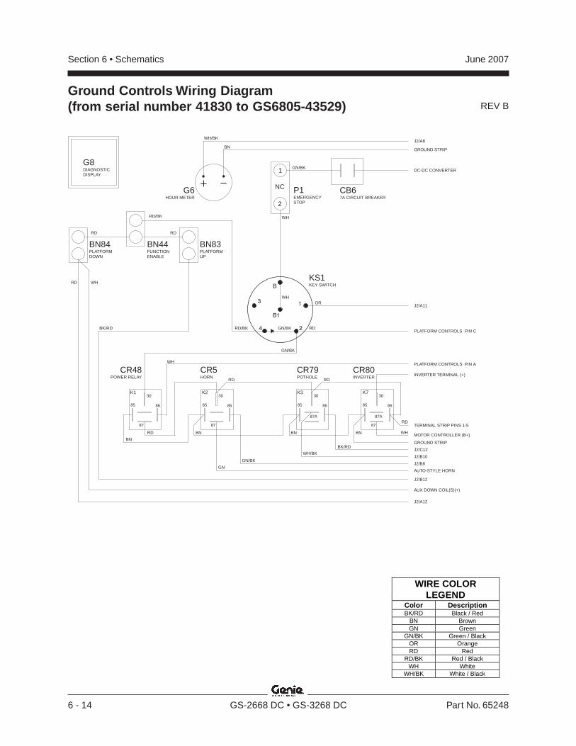
REV B
Section 6 • Schematics June 2007
6 - 14 GS-2668 DC • GS-3268 DC Part No. 65248
Ground Controls Wiring Diagram(from serial number 41830 to GS6805-43529)
P1EMERGENCYSTOP
NC
1
2
G6HOUR METER
CB67A CIRCUIT BREAKER
GN/BK
WH
WH
WH/BK
BN
RDRD
RD WH
RD
OR
BN44FUNCTIONENABLE
J2/A8
GROUND STRIP
PLATFORM CONTROLS PIN C
J2/A11
DC-DC CONVERTER
RD/BK
RD/BKBK/RD
J2/B12
J2/A12
AUX DOWN COIL(S)(+)
CR48POWER RELAY
CR5HORN
CR79POTHOLE
WH/BK
GN/BK
BK/RD
BN
BN BN BN
WH
RD
RD RD
PLATFORM CONTROLS PIN A
GROUND STRIP
TERMINAL STRIP PINS 1-5
J2/C12
J2/B10
J2/B8
AUTO-STYLE HORN
K130
87
8685
K230
87
8685
K330
87A
8685
G8DIAGNOSTICDISPLAY
GN/BK
GN/BK
B
B1
31
4 2
CR80INVERTER INVERTER TERMINAL (+)
30
87A
87
8685
K7
BN83PLATFORMUP
BN84PLATFORMDOWN
KS1KEY SWITCH
GN
RD
WHMOTOR CONTROLLER (B+)
WIRE COLOR LEGEND
Color Description BK/RD Black / Red
BN Brown GN Green
GN/BK Green / Black OR Orange RD Red
RD/BK Red / Black WH White
WH/BK White / Black

REV A
Section 6 • SchematicsJune 2007
Part No. 65248 GS-2668 DC • GS-3268 DC 6 - 15
Ground Controls Wiring Diagram(after serial number GS6805-43529)
P1EMERGENCY
STOPNC
G6HOUR METER
CB67A CIRCUIT BREAKER
GN/BK
WH
WH
WH/BK
BN
RDRD
RD
BK
OR
BN44FUNCTIONENABLE
J2/A8
GROUND STRIP
PLATFORM CONTROLS PIN C
J2/A11
DC-DC CONVERTER
RD/BK
RD/BKBK/RD
J2/B12
J2/A12
AUX DOWN COIL(S)(+)
CR48POWER RELAY
CR5HORN
CR79POTHOLE
WH/BK
GN/BK
BK/RD
BN
BN BN BN
WH
RD
RD RD
PLATFORM CONTROLS PIN A
GROUND STRIP
TERMINAL STRIP PINS 1-5
J2/C12
J2/B10
J2/B8
AUTO-STYLE HORN
K130
87
8685
K230
87
8685
K330
87A
8685
G8DIAGNOSTICDISPLAY
GN/BK
GN/BK
B
B1
31
4 2
CR80INVERTER INVERTER TERMINAL (+)
30
87A
87
8685
K7
BN83PLATFORMUP
BN84PLATFORMDOWN
KS1KEY SWITCH
NC
F105A FUSE
BN92AUXILIARYDOWN
RD
GN
YL
WH
MOTOR CONTROLLER (B+)WH
RD
ABBREVIATION LEGEND Item Description
Button BN BN12 = Function enable up/down BN83 = Platform up BN84 = Platform down BN92 = Auxiliary down
CB 7 amp circuit breaker Control relay CR CR5 = Horn (option) CR48 = Power CR79 = Pothole CR80 = Inverter
F 5 Amp fuse Gauge G G6 = Hour meter G8 = Diagnostic display
KS1 Key switch P1 Emergency Stop button at ground controls
WIRE COLOR LEGEND
Color Description BK/RD Black / Red
BN Brown GN Green
GN/BK Green / Black OR Orange RD Red
RD/BK Red / Black WH White
WH/BK White / Black YL Yellow
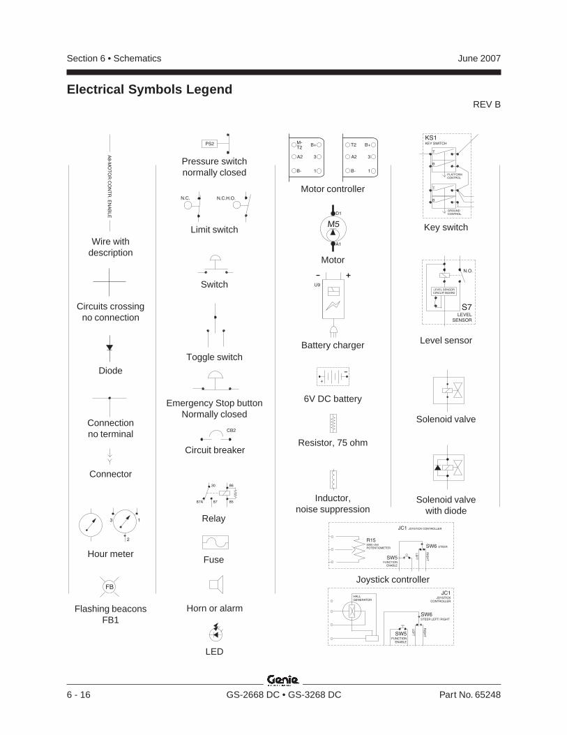
REV B
Section 6 • Schematics June 2007
6 - 16 GS-2668 DC • GS-3268 DC Part No. 65248
-
+
U9
CB2
13
2
FB
PLATFORM
CONTROL
T
B
B
T
GROUND
CONTROL
KS1KEY SWITCH
A8
-MO
TO
RC
ON
TR
.E
NA
BL
E
N.C.H.O.N.C.
PS2 B+
3A2
T2
B- 1
B+
3A2
T2
M-
B- 1
87A 85
8630
87
A1
D1
M5
N.O.
S7LEVEL
SENSOR
LEVEL SENSOR
CIRCUIT BOARD
JC1 JOYSTICK CONTROLLER
R155000 ohm
POTENTIOMETERSW6 STEER
LE
FT
RIG
HTSW5
FUNCTION
ENABLE
JC1JOYSTICK
CONTROLLER
HALL
GENERATOR
SW6STEER LEFT/ RIGHT
LE
FT
RIG
HTSW5
FUNCTION
ENABLE
Wire withdescription
Circuits crossingno connection
Diode
Connectionno terminal
Connector
Hour meter
Flashing beaconsFB1
Pressure switchnormally closed
Limit switch
Switch
Toggle switch
Emergency Stop buttonNormally closed
Circuit breaker
Relay
Fuse
Horn or alarm
Motor controller
Motor
Battery charger
6V DC battery
Resistor, 75 ohm
Inductor,noise suppression
Key switch
Level sensor
Solenoid valve
Solenoid valvewith diode
Joystick controller
LED
Electrical Symbols Legend

Section 6 • SchematicsJune 2007
6 - 17 6 - 18
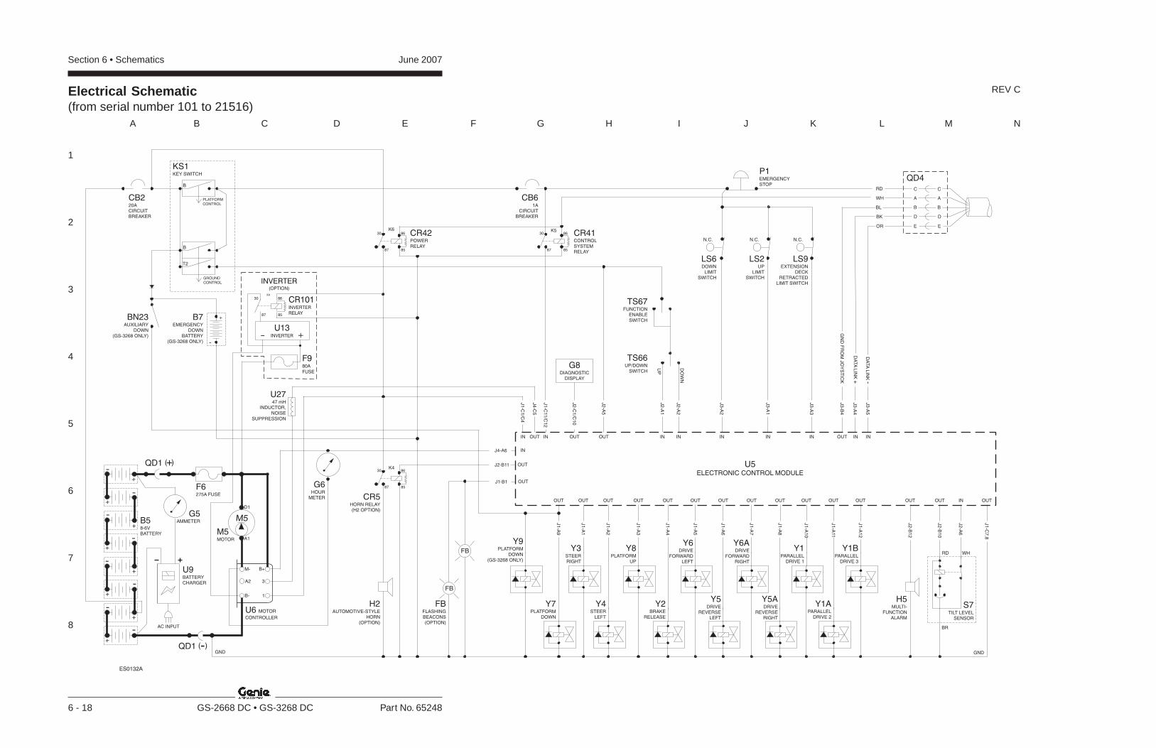
Section 6 • Schematics June 2007
1
2
3
4
5
6
7
8
A B C D E F G H I J K L M N
6 - 18 GS-2668 DC • GS-3268 DC Part No. 65248
REV CElectrical Schematic(from serial number 101 to 21516)
BR
RD WH
GND
G6HOUR
METER CR5HORN RELAY(H2 OPTION)
H2
HORN(OPTION)
AUTOMOTIVE-STYLE
Y3STEERRIGHT
Y8PLATFORM
UP
Y4STEER
LEFT
J2-B11
J4-A6
J1
-C1
/C4
IN
OUTOUT OUT
IN
J4
-C5
H5MULTI-
FUNCTIONALARM
OUT OUT IN
J2
-B1
2
J2
-B1
0
J2
-A6
OUT
J1
-C7
,8
J1
-A2
J1
-A1
J1
-A3
Y6DRIVE
FORWARDLEFT
Y2BRAKE
RELEASE
OUT OUT
J1
-A4
J1
-A5
Y6ADRIVE
FORWARDRIGHT
Y5DRIVE
REVERSELEFT
OUT OUT
J1
-A6
J1
-A7
Y5ADRIVE
REVERSERIGHT
OUT
J1
-A8
Y1BPARALLEL
DRIVE 3
Y1APARALLEL
DRIVE 2
OUT OUT
J1
-A11
J1
-A1
2
Y1PARALLEL
DRIVE 1
Y9PLATFORM
DOWN(GS-3268 ONLY)
OUT
J1
-A9
OUT
J1
-A1
0
J1
-C11
/C1
2
U5ELECTRONIC CONTROL MODULE
OUT
IN
S7TILT LEVEL
SENSOR
J1-B1 OUT
FB
FB
FB
(OPTION)
FLASHINGBEACONS
PLATFORMCONTROL
B
T2
B
GROUNDCONTROL
KS1KEY SWITCH
CB61A
CIRCUITBREAKER
K5K6
K4
8587
8630
8587
8630
8587
8630
IN IN IN INOUTOUT
UP
DO
WN
J2
-A1
J2
-A2
J3
-A2
J3
-A1
J2
-A5
J2
-C1
/C1
0
TS67FUNCTION
ENABLESWITCH
TS66UP/DOWN
SWITCH
LS6DOWN
LIMITSWITCH
N.C.
LS2UP
LIMITSWITCH
N.C.
P1EMERGENCYSTOP
G8DIAGNOSTIC
DISPLAY
B58-6VBATTERY
GND
F6275A FUSE
U6 MOTOR
CONTROLLER
B+
3A2
M-
B- 1
U9BATTERYCHARGER
G5AMMETER
M5MOTOR A1
D1
M5
AC INPUT
QD1 -( )
QD1 +( )
OUT
Y7PLATFORM
DOWN
+
-
-
+
+-
-+
++
-
--
-+
+
IN
J3
-A3
LS9EXTENSION
DECKRETRACTED
LIMIT SWITCH
N.C.
CB220ACIRCUITBREAKER
CR42POWERRELAY
CR41CONTROLSYSTEMRELAY
IN INOUT
J3
-B4
J3
-A4
J3
-A5
DA
TA
LIN
K-
DA
TA
LIN
K+
GN
DF
RO
MJO
YS
TIC
K
QD4
A A
C C
B B
D D
RD
WH
BL
BK
OR E E
ES0132A
U2747 mH
INDUCTOR,NOISE
SUPPRESSION
B7EMERGENCY
DOWNBATTERY
(GS-3268 ONLY) -
+
INVERTER(OPTION)
8587
86
K4
30
+-U13
INVERTER
CR101INVERTER
RELAY
F980A
FUSE
BN23AUXILIARY
DOWN(GS-3268 ONLY)
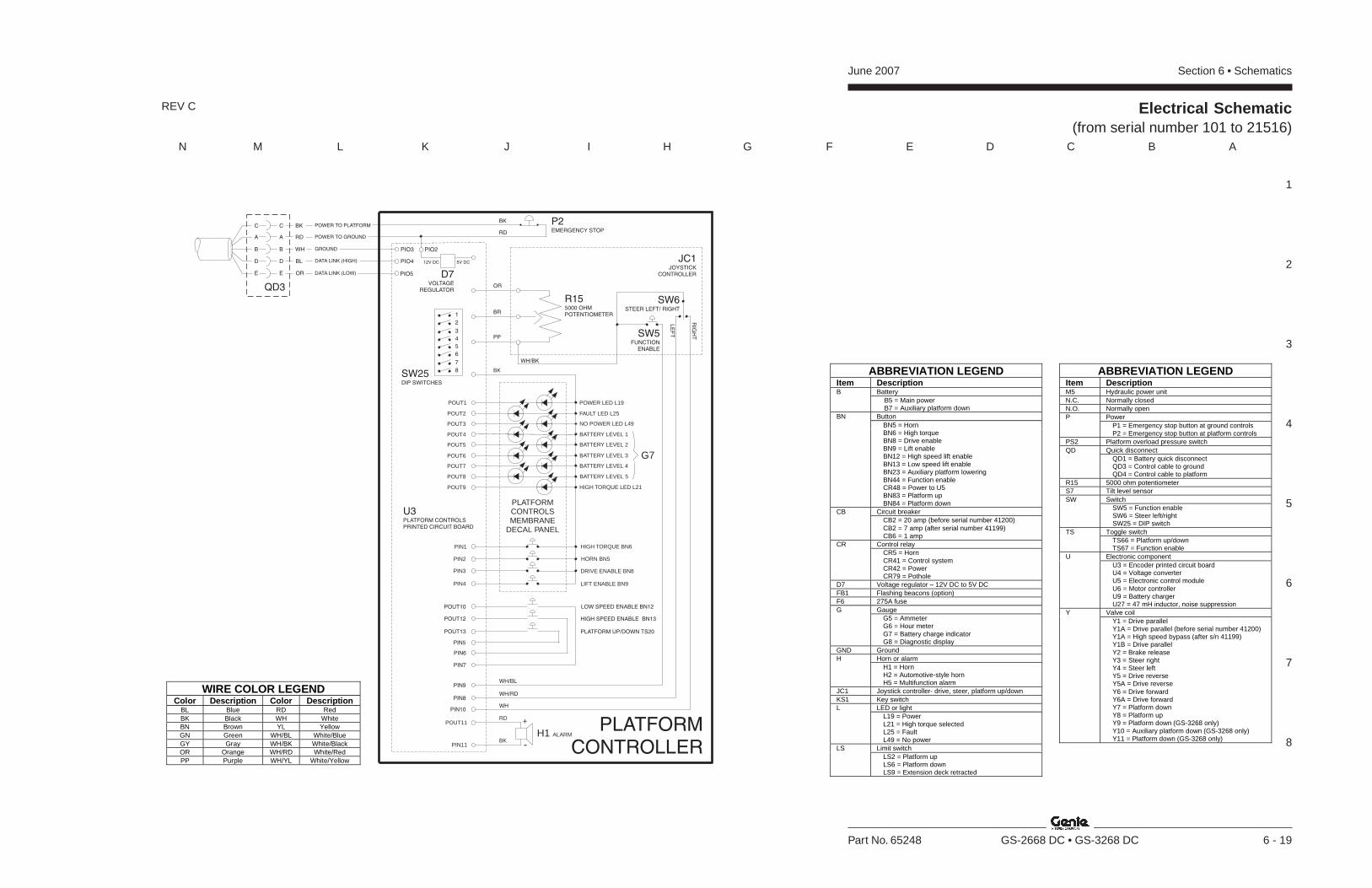
Section 6 • SchematicsJune 2007
1
2
3
4
5
6
7
8
N M L K J I H G F E D C B A
Part No. 65248 GS-2668 DC • GS-3268 DC 6 - 19
REV C Electrical Schematic(from serial number 101 to 21516)
ABBREVIATION LEGENDItem Description
BatteryB B5 = Main power B7 = Auxiliary platform downButtonBN
BN5 = HornBN6 = High torqueBN8 = Drive enableBN9 = Lift enableBN12 = High speed lift enableBN13 = Low speed lift enableBN23 = Auxiliary platform loweringBN44 = Function enableCR48 = Power to U5BN83 = Platform upBN84 = Platform down
Circuit breakerCBCB2 = 20 amp (before serial number 41200)CB2 = 7 amp (after serial number 41199)CB6 = 1 amp
Control relayCRCR5 = HornCR41 = Control systemCR42 = PowerCR79 = Pothole
D7 Voltage regulator – 12V DC to 5V DCFB1 Flashing beacons (option)F6 275A fuse
GaugeGG5 = AmmeterG6 = Hour meterG7 = Battery charge indicatorG8 = Diagnostic display
GND GroundHorn or alarmH
H1 = HornH2 = Automotive-style hornH5 = Multifunction alarm
JC1 Joystick controller- drive, steer, platform up/downKS1 Key switch
LED or lightLL19 = PowerL21 = High torque selectedL25 = FaultL49 = No power
Limit switchLSLS2 = Platform upLS6 = Platform downLS9 = Extension deck retracted
ABBREVIATION LEGENDItem DescriptionM5 Hydraulic power unitN.C. Normally closedN.O. Normally open
PowerPP1 = Emergency stop button at ground controlsP2 = Emergency stop button at platform controls
PS2 Platform overload pressure switchQuick disconnectQD
QD1 = Battery quick disconnectQD3 = Control cable to groundQD4 = Control cable to platform
R15 5000 ohm potentiometerS7 Tilt level sensor
SwitchSWSW5 = Function enableSW6 = Steer left/rightSW25 = DIP switch
Toggle switchTSTS66 = Platform up/downTS67 = Function enable
Electronic componentUU3 = Encoder printed circuit boardU4 = Voltage converterU5 = Electronic control moduleU6 = Motor controllerU9 = Battery chargerU27 = 47 mH inductor, noise suppression
Valve coilYY1 = Drive parallelY1A = Drive parallel (before serial number 41200)Y1A = High speed bypass (after s/n 41199)Y1B = Drive parallelY2 = Brake releaseY3 = Steer rightY4 = Steer leftY5 = Drive reverseY5A = Drive reverseY6 = Drive forwardY6A = Drive forwardY7 = Platform downY8 = Platform upY9 = Platform down (GS-3268 only)Y10 = Auxiliary platform down (GS-3268 only)Y11 = Platform down (GS-3268 only)
WIRE COLOR LEGENDColor Description Color Description
BL Blue RD RedBK Black WH WhiteBN Brown YL YellowGN Green WH/BL White/BlueGY Gray WH/BK White/BlackOR Orange WH/RD White/RedPP Purple WH/YL White/Yellow
PLATFORMCONTROLLER
PIN8
PIN10
PIN9
H1 ALARM
POUT11
PIN11
RD +
-BK
WH/BK
P2EMERGENCY STOP
BK
RD
1
2
3
4
8
5
7
6
SW25DIP SWITCHES
PIO3 PIO2
PIO5
PIO4 5V DC12V DC
D7VOLTAGE
REGULATOR
DATA LINK (LOW)
DATA LINK (HIGH)
GROUND
POWER TO GROUND
POWER TO PLATFORMBK
A A RD
C C
WHB B
BLD D
ORE E
QD3
JC1JOYSTICK
CONTROLLER
SW6STEER LEFT/ RIGHT
LE
FT
RIG
HTSW5
FUNCTIONENABLE
R155000 OHMPOTENTIOMETER
OR
BR
PP
HORN BN5
DRIVE ENABLE BN8
HIGH TORQUE BN6PIN1
PIN2
PIN3
LIFT ENABLE BN9PIN4
POWER LED L19
HIGH TORQUE LED L21
POUT4
POUT2
POUT3
FAULT LED L25
POUT5
POUT6
POUT7
POUT9
POUT8
NO POWER LED L49
POUT1
BATTERY LEVEL 1
BATTERY LEVEL 2
BATTERY LEVEL 3
BATTERY LEVEL 4
BATTERY LEVEL 5
G7
PLATFORMCONTROLSMEMBRANE
DECAL PANEL
BK
WH/BL
WH/RD
WH
LOW SPEED ENABLE BN12
HIGH SPEED ENABLE BN13
PIN5
PIN6
PLATFORM UP/DOWN TS20
PIN7
U3PLATFORM CONTROLSPRINTED CIRCUIT BOARD
POUT10
POUT12
POUT13

June 2007 Section 6 • Schematics
6 - 20
Electrical Schematic (from serial number 101 to 21516)
6 - 19
Section 6 • SchematicsJune 2007
6 - 21 6 - 22
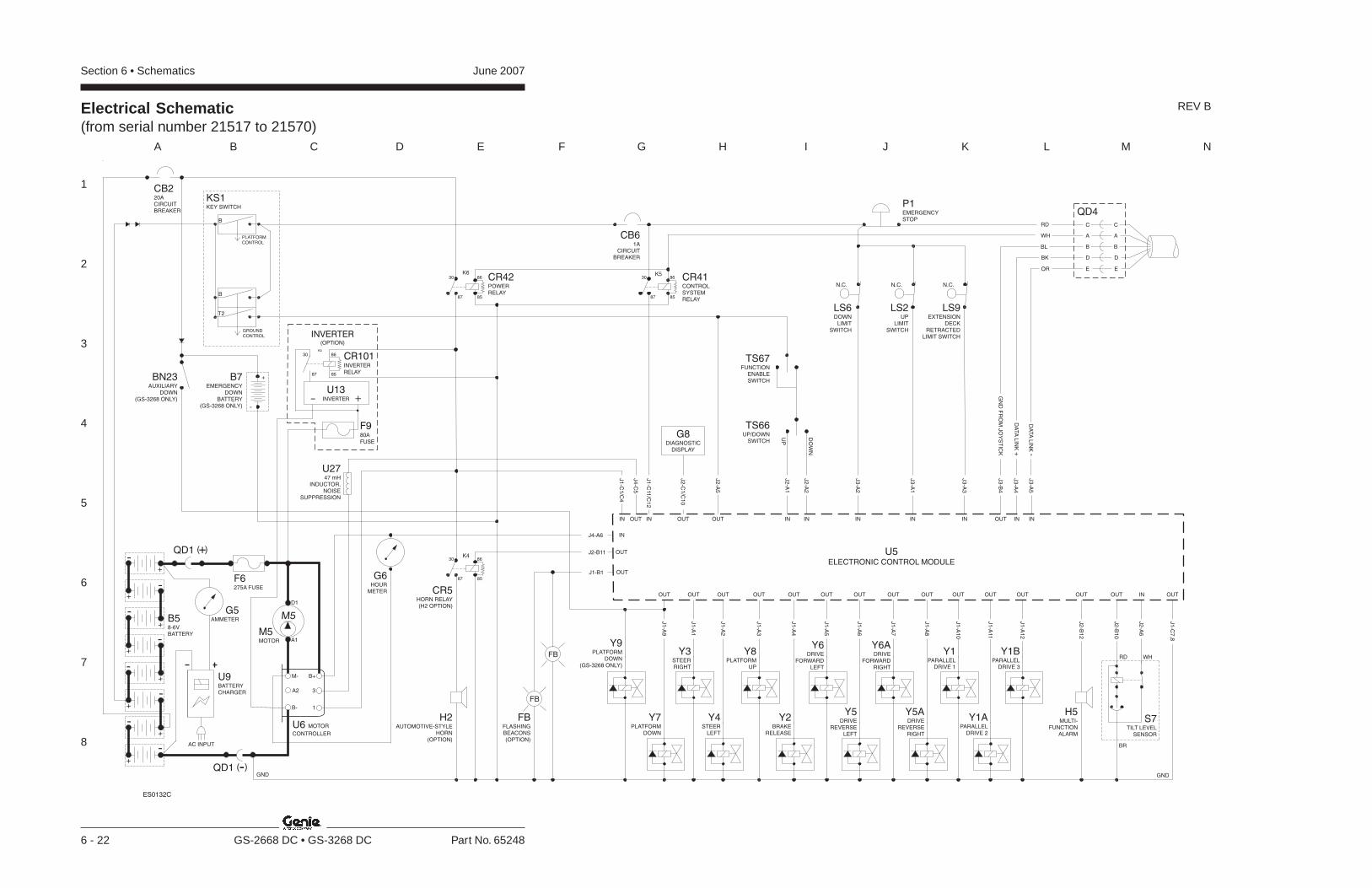
Section 6 • Schematics June 2007
1
2
3
4
5
6
7
8
A B C D E F G H I J K L M N
6 - 22 GS-2668 DC • GS-3268 DC Part No. 65248
REV BElectrical Schematic(from serial number 21517 to 21570)
BR
RD WH
GND
G6HOUR
METER CR5HORN RELAY(H2 OPTION)
H2
HORN(OPTION)
AUTOMOTIVE-STYLE
Y3STEERRIGHT
Y8PLATFORM
UP
Y4STEER
LEFT
J2-B11
J4-A6
J1
-C1
/C4
IN
OUTOUT OUT
IN
J4
-C5
H5MULTI-
FUNCTIONALARM
OUT OUT IN
J2
-B1
2
J2
-B1
0
J2
-A6
OUT
J1
-C7
,8
J1
-A2
J1
-A1
J1
-A3
Y6DRIVE
FORWARDLEFT
Y2BRAKE
RELEASE
OUT OUT
J1
-A4
J1
-A5
Y6ADRIVE
FORWARDRIGHT
Y5DRIVE
REVERSELEFT
OUT OUT
J1
-A6
J1
-A7
Y5ADRIVE
REVERSERIGHT
OUT
J1
-A8
Y1BPARALLEL
DRIVE 3
Y1APARALLEL
DRIVE 2
OUT OUT
J1
-A11
J1
-A1
2
Y1PARALLEL
DRIVE 1
Y9PLATFORM
DOWN(GS-3268 ONLY)
OUT
J1
-A9
OUT
J1
-A1
0
J1
-C11
/C1
2
U5ELECTRONIC CONTROL MODULE
OUT
IN
S7TILT LEVEL
SENSOR
BN23AUXILIARY
DOWN(GS-3268 ONLY)
B7EMERGENCY
DOWNBATTERY
(GS-3268 ONLY) -
+
J1-B1 OUT
FB
FB
FB
(OPTION)
FLASHINGBEACONS
PLATFORMCONTROL
B
T2
B
GROUNDCONTROL
KS1KEY SWITCH
CB61A
CIRCUITBREAKER
K5K6
K4
8587
8630
8587
8630
8587
8630
IN IN IN INOUTOUT
UP
DO
WN
J2
-A1
J2
-A2
J3
-A2
J3
-A1
J2
-A5
J2
-C1
/C1
0
TS67FUNCTION
ENABLESWITCH
TS66UP/DOWN
SWITCH
LS6DOWN
LIMITSWITCH
N.C.
LS2UP
LIMITSWITCH
N.C.
P1EMERGENCYSTOP
B58-6VBATTERY
GND
F6275A FUSE
U6 MOTOR
CONTROLLER
B+
3A2
M-
B- 1
U9BATTERYCHARGER
G5AMMETER
M5MOTOR A1
D1
M5
AC INPUT
QD1 -( )
QD1 +( )
OUT
Y7PLATFORM
DOWN
+
-
-
+
+-
-+
++
-
--
-+
+
IN
J3
-A3
LS9EXTENSION
DECKRETRACTED
LIMIT SWITCH
N.C.
CB220ACIRCUITBREAKER
CR42POWERRELAY
CR41CONTROLSYSTEMRELAY
G8DIAGNOSTIC
DISPLAY
IN INOUT
J3
-B4
J3
-A4
J3
-A5
DA
TA
LIN
K-
DA
TA
LIN
K+
GN
DF
RO
MJO
YS
TIC
K
QD4
A A
C C
B B
D D
RD
WH
BL
BK
OR E E
ES0132C
U2747 mH
INDUCTOR,NOISE
SUPPRESSION
INVERTER(OPTION)
8587
86
K4
30
+-U13
INVERTER
CR101INVERTER
RELAY
F980A
FUSE
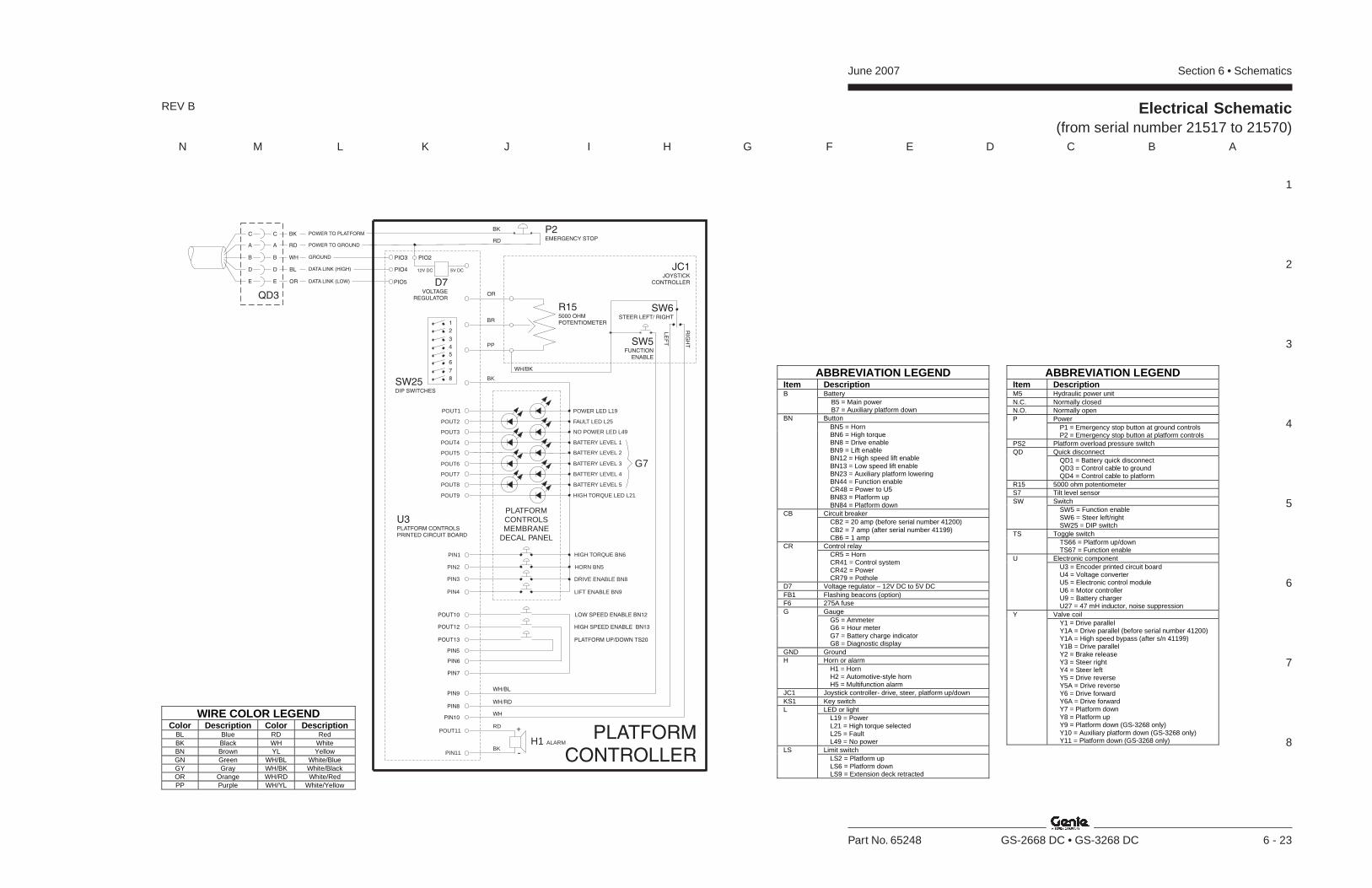
Section 6 • SchematicsJune 2007
1
2
3
4
5
6
7
8
N M L K J I H G F E D C B A
Part No. 65248 GS-2668 DC • GS-3268 DC 6 - 23
REV B Electrical Schematic(from serial number 21517 to 21570)
ABBREVIATION LEGENDItem Description
BatteryB B5 = Main power B7 = Auxiliary platform downButtonBN
BN5 = HornBN6 = High torqueBN8 = Drive enableBN9 = Lift enableBN12 = High speed lift enableBN13 = Low speed lift enableBN23 = Auxiliary platform loweringBN44 = Function enableCR48 = Power to U5BN83 = Platform upBN84 = Platform down
Circuit breakerCBCB2 = 20 amp (before serial number 41200)CB2 = 7 amp (after serial number 41199)CB6 = 1 amp
Control relayCRCR5 = HornCR41 = Control systemCR42 = PowerCR79 = Pothole
D7 Voltage regulator – 12V DC to 5V DCFB1 Flashing beacons (option)F6 275A fuse
GaugeGG5 = AmmeterG6 = Hour meterG7 = Battery charge indicatorG8 = Diagnostic display
GND GroundHorn or alarmH
H1 = HornH2 = Automotive-style hornH5 = Multifunction alarm
JC1 Joystick controller- drive, steer, platform up/downKS1 Key switch
LED or lightLL19 = PowerL21 = High torque selectedL25 = FaultL49 = No power
Limit switchLSLS2 = Platform upLS6 = Platform downLS9 = Extension deck retracted
ABBREVIATION LEGENDItem DescriptionM5 Hydraulic power unitN.C. Normally closedN.O. Normally open
PowerPP1 = Emergency stop button at ground controlsP2 = Emergency stop button at platform controls
PS2 Platform overload pressure switchQuick disconnectQD
QD1 = Battery quick disconnectQD3 = Control cable to groundQD4 = Control cable to platform
R15 5000 ohm potentiometerS7 Tilt level sensor
SwitchSWSW5 = Function enableSW6 = Steer left/rightSW25 = DIP switch
Toggle switchTSTS66 = Platform up/downTS67 = Function enable
Electronic componentUU3 = Encoder printed circuit boardU4 = Voltage converterU5 = Electronic control moduleU6 = Motor controllerU9 = Battery chargerU27 = 47 mH inductor, noise suppression
Valve coilYY1 = Drive parallelY1A = Drive parallel (before serial number 41200)Y1A = High speed bypass (after s/n 41199)Y1B = Drive parallelY2 = Brake releaseY3 = Steer rightY4 = Steer leftY5 = Drive reverseY5A = Drive reverseY6 = Drive forwardY6A = Drive forwardY7 = Platform downY8 = Platform upY9 = Platform down (GS-3268 only)Y10 = Auxiliary platform down (GS-3268 only)Y11 = Platform down (GS-3268 only)
WIRE COLOR LEGENDColor Description Color Description
BL Blue RD RedBK Black WH WhiteBN Brown YL YellowGN Green WH/BL White/BlueGY Gray WH/BK White/BlackOR Orange WH/RD White/RedPP Purple WH/YL White/Yellow
PLATFORMCONTROLLER
PIN8
PIN10
PIN9
H1 ALARM
POUT11
PIN11
RD +
-BK
WH/BK
P2EMERGENCY STOP
BK
RD
1
2
3
4
8
5
7
6
SW25DIP SWITCHES
PIO3 PIO2
PIO5
PIO4 5V DC12V DC
D7VOLTAGE
REGULATOR
DATA LINK (LOW)
DATA LINK (HIGH)
GROUND
POWER TO GROUND
POWER TO PLATFORMBK
A A RD
C C
WHB B
BLD D
ORE E
QD3
JC1JOYSTICK
CONTROLLER
SW6STEER LEFT/ RIGHT
LE
FT
RIG
HTSW5
FUNCTIONENABLE
R155000 OHMPOTENTIOMETER
OR
BR
PP
HORN BN5
DRIVE ENABLE BN8
HIGH TORQUE BN6PIN1
PIN2
PIN3
LIFT ENABLE BN9PIN4
POWER LED L19
HIGH TORQUE LED L21
POUT4
POUT2
POUT3
FAULT LED L25
POUT5
POUT6
POUT7
POUT9
POUT8
NO POWER LED L49
POUT1
BATTERY LEVEL 1
BATTERY LEVEL 2
BATTERY LEVEL 3
BATTERY LEVEL 4
BATTERY LEVEL 5
G7
PLATFORMCONTROLSMEMBRANE
DECAL PANEL
BK
WH/BL
WH/RD
WH
LOW SPEED ENABLE BN12
HIGH SPEED ENABLE BN13
PIN5
PIN6
PLATFORM UP/DOWN TS20
PIN7
U3PLATFORM CONTROLSPRINTED CIRCUIT BOARD
POUT10
POUT12
POUT13

June 2007 Section 6 • Schematics
6 - 24
Electrical Schematic(from serial number 21517 to 21570)
6 - 23

Section 6 • SchematicsJune 2007
6 - 25 6 - 26

Section 6 • Schematics June 2007
1
2
3
4
5
6
7
8
A B C D E F G H I J K L M N
6 - 26 GS-2668 DC • GS-3268 DC Part No. 65248
Electrical Schematic(from serial number 21571 to 26562)
REV B
BR
RD WH
GND
CR5HORN RELAY(H2 OPTION)
H2
HORN(OPTION)
AUTOMOTIVE-STYLE
Y3STEERRIGHT
Y8PLATFORM
UP
Y4STEER
LEFT
J2-B11
J4-A6
J1
-C1
/C4
IN
OUTOUT OUT
IN
J4
-C5
H5MULTI-
FUNCTIONALARM
OUT OUT IN
J2
-B1
2
J2
-B1
0
J2
-A6
OUT
J1
-C7
,8
J1
-A2
J1
-A1
J1
-A3
Y6DRIVE
FORWARDLEFT
Y2BRAKE
RELEASE
OUT OUT
J1
-A4
J1
-A5
Y6ADRIVE
FORWARDRIGHT
Y5DRIVE
REVERSELEFT
OUT OUT
J1
-A6
J1
-A7
Y5ADRIVE
REVERSERIGHT
OUT
J1
-A8
Y1BPARALLEL
DRIVE 3
Y1APARALLEL
DRIVE 2
OUT OUT
J1
-A11
J1
-A1
2
Y1PARALLEL
DRIVE 1
Y9PLATFORM
DOWN(GS-3268 ONLY)
OUT
J1
-A9
OUT
J1
-A1
0
J1
-C11
/C1
2
U5ELECTRONIC CONTROL MODULE
OUT
IN
S7TILT LEVEL
SENSOR
BN23AUXILIARY
DOWN(GS-3268 ONLY)
B7EMERGENCY
DOWNBATTERY
(GS-3268 ONLY) -
+
J1-B1 OUT
FB
FB
FB
(OPTION)
FLASHINGBEACONS
PLATFORMCONTROL
B
T2
B
GROUNDCONTROL
KS1KEY SWITCH
CB61A
CIRCUITBREAKER
K5K6
K4
8587
8630
8587
8630
8587
8630
IN IN IN INOUTOUT
UP
DO
WN
J2
-A1
J2
-A2
J3
-A2
J3
-A1
J2
-A5
J2
-C1
/C1
0
TS67FUNCTION
ENABLESWITCH
TS66UP/DOWN
SWITCH
LS6DOWN
LIMITSWITCH
N.C.
LS2UP
LIMITSWITCH
N.C.
P1EMERGENCYSTOP
B58-6VBATTERY
GND
F6275A FUSE
U6 MOTOR
CONTROLLER
B+
3A2
M-
B- 1
U9BATTERYCHARGER
G5AMMETER
M5MOTOR A1
D1
M5
AC INPUT
QD1 -( )
QD1 +( )
OUT
Y7PLATFORM
DOWN
+
-
-
+
+-
-+
++
-
--
-+
+
IN
J3
-A3
LS9EXTENSION
DECKRETRACTED
LIMIT SWITCH
N.C.
CB220ACIRCUITBREAKER
G6HOUR
METER
1
2
3
CR42POWERRELAY
CR41CONTROLSYSTEMRELAY
G8DIAGNOSTIC
DISPLAY
IN INOUT
J3
-B4
J3
-A4
J3
-A5
DA
TA
LIN
K-
DA
TA
LIN
K+
GN
DF
RO
MJO
YS
TIC
K
QD4
A A
C C
B B
D D
RD
WH
BL
BK
OR E E
ES0132F
U2747 mH
INDUCTOR,NOISE
SUPPRESSION
INVERTER(OPTION)
8587
86
K4
30
+-U13
INVERTER
CR101INVERTER
RELAY
F980A
FUSE
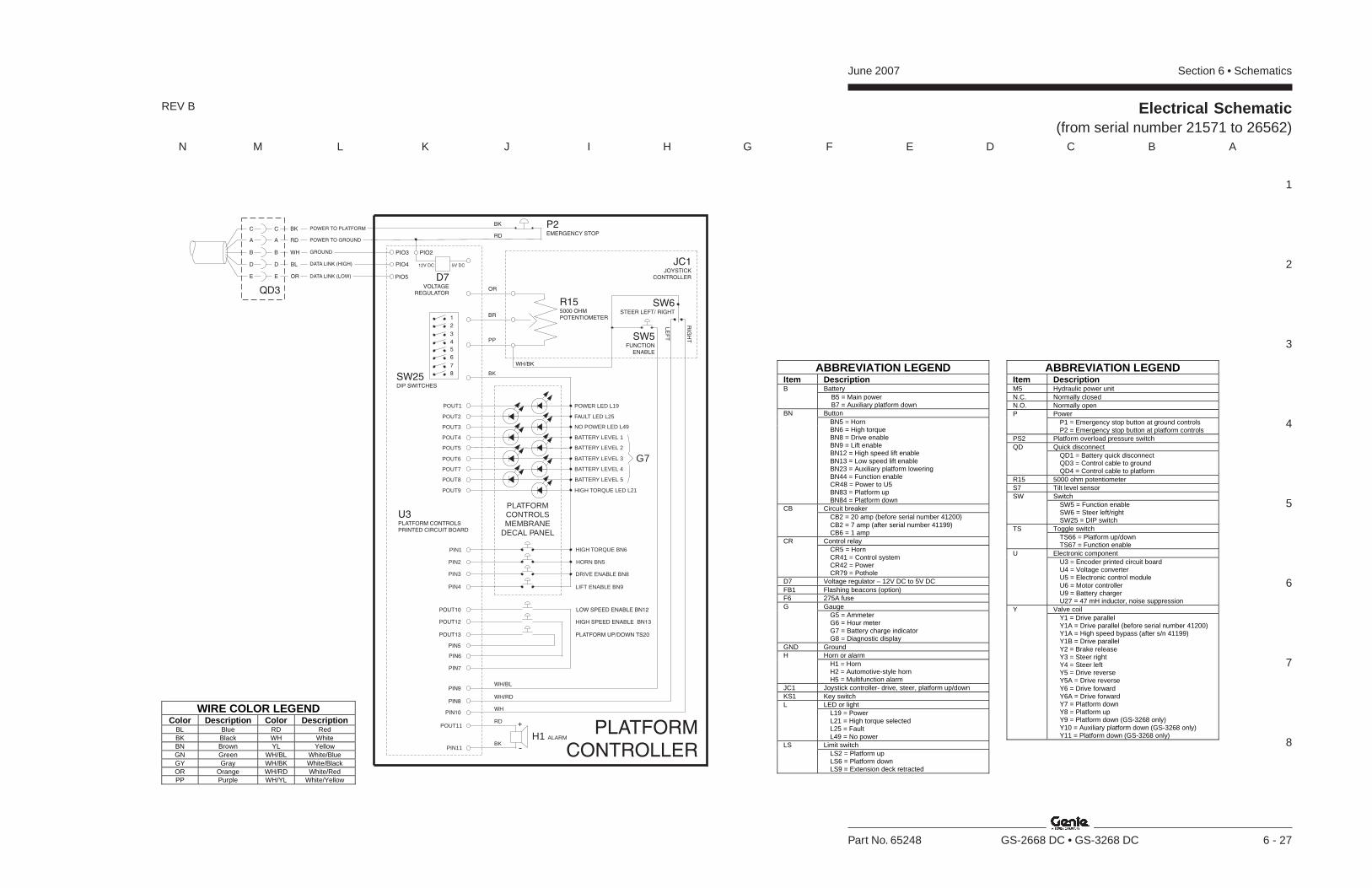
Section 6 • SchematicsJune 2007
1
2
3
4
5
6
7
8
N M L K J I H G F E D C B A
Part No. 65248 GS-2668 DC • GS-3268 DC 6 - 27
Electrical Schematic(from serial number 21571 to 26562)
REV B
ABBREVIATION LEGENDItem Description
BatteryB B5 = Main power B7 = Auxiliary platform downButtonBN
BN5 = HornBN6 = High torqueBN8 = Drive enableBN9 = Lift enableBN12 = High speed lift enableBN13 = Low speed lift enableBN23 = Auxiliary platform loweringBN44 = Function enableCR48 = Power to U5BN83 = Platform upBN84 = Platform down
Circuit breakerCBCB2 = 20 amp (before serial number 41200)CB2 = 7 amp (after serial number 41199)CB6 = 1 amp
Control relayCRCR5 = HornCR41 = Control systemCR42 = PowerCR79 = Pothole
D7 Voltage regulator – 12V DC to 5V DCFB1 Flashing beacons (option)F6 275A fuse
GaugeGG5 = AmmeterG6 = Hour meterG7 = Battery charge indicatorG8 = Diagnostic display
GND GroundHorn or alarmH
H1 = HornH2 = Automotive-style hornH5 = Multifunction alarm
JC1 Joystick controller- drive, steer, platform up/downKS1 Key switch
LED or lightLL19 = PowerL21 = High torque selectedL25 = FaultL49 = No power
Limit switchLSLS2 = Platform upLS6 = Platform downLS9 = Extension deck retracted
ABBREVIATION LEGENDItem DescriptionM5 Hydraulic power unitN.C. Normally closedN.O. Normally open
PowerPP1 = Emergency stop button at ground controlsP2 = Emergency stop button at platform controls
PS2 Platform overload pressure switchQuick disconnectQD
QD1 = Battery quick disconnectQD3 = Control cable to groundQD4 = Control cable to platform
R15 5000 ohm potentiometerS7 Tilt level sensor
SwitchSWSW5 = Function enableSW6 = Steer left/rightSW25 = DIP switch
Toggle switchTSTS66 = Platform up/downTS67 = Function enable
Electronic componentUU3 = Encoder printed circuit boardU4 = Voltage converterU5 = Electronic control moduleU6 = Motor controllerU9 = Battery chargerU27 = 47 mH inductor, noise suppression
Valve coilYY1 = Drive parallelY1A = Drive parallel (before serial number 41200)Y1A = High speed bypass (after s/n 41199)Y1B = Drive parallelY2 = Brake releaseY3 = Steer rightY4 = Steer leftY5 = Drive reverseY5A = Drive reverseY6 = Drive forwardY6A = Drive forwardY7 = Platform downY8 = Platform upY9 = Platform down (GS-3268 only)Y10 = Auxiliary platform down (GS-3268 only)Y11 = Platform down (GS-3268 only)
WIRE COLOR LEGENDColor Description Color Description
BL Blue RD RedBK Black WH WhiteBN Brown YL YellowGN Green WH/BL White/BlueGY Gray WH/BK White/BlackOR Orange WH/RD White/RedPP Purple WH/YL White/Yellow
PLATFORMCONTROLLER
PIN8
PIN10
PIN9
H1 ALARM
POUT11
PIN11
RD +
-BK
WH/BK
P2EMERGENCY STOP
BK
RD
1
2
3
4
8
5
7
6
SW25DIP SWITCHES
PIO3 PIO2
PIO5
PIO4 5V DC12V DC
D7VOLTAGE
REGULATOR
DATA LINK (LOW)
DATA LINK (HIGH)
GROUND
POWER TO GROUND
POWER TO PLATFORMBK
A A RD
C C
WHB B
BLD D
ORE E
QD3
JC1JOYSTICK
CONTROLLER
SW6STEER LEFT/ RIGHT
LE
FT
RIG
HTSW5
FUNCTIONENABLE
R155000 OHMPOTENTIOMETER
OR
BR
PP
HORN BN5
DRIVE ENABLE BN8
HIGH TORQUE BN6PIN1
PIN2
PIN3
LIFT ENABLE BN9PIN4
POWER LED L19
HIGH TORQUE LED L21
POUT4
POUT2
POUT3
FAULT LED L25
POUT5
POUT6
POUT7
POUT9
POUT8
NO POWER LED L49
POUT1
BATTERY LEVEL 1
BATTERY LEVEL 2
BATTERY LEVEL 3
BATTERY LEVEL 4
BATTERY LEVEL 5
G7
PLATFORMCONTROLSMEMBRANE
DECAL PANEL
BK
WH/BL
WH/RD
WH
LOW SPEED ENABLE BN12
HIGH SPEED ENABLE BN13
PIN5
PIN6
PLATFORM UP/DOWN TS20
PIN7
U3PLATFORM CONTROLSPRINTED CIRCUIT BOARD
POUT10
POUT12
POUT13

June 2007 Section 6 • Schematics
6 - 28
Electrical Schematic(from serial number 21571 to 26562)
6 - 27

Section 6 • SchematicsJune 2007
6 - 29 6 - 30
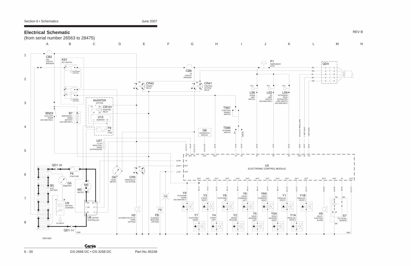
Section 6 • Schematics June 2007
1
2
3
4
5
6
7
8
A B C D E F G H I J K L M N
6 - 30 GS-2668 DC • GS-3268 DC Part No. 65248
Electrical Schematic(from serial number 26563 to 28475)
REV B
BR
RD WH
GND
CR5HORN RELAY(H2 OPTION)
H2
HORN(OPTION)
AUTOMOTIVE-STYLE
Y3STEERRIGHT
Y8PLATFORM
UP
Y4STEER
LEFT
J2-B11
J4-A6
J1
-C1
/C4
IN
OUTOUT OUT
IN
J4
-C5
H5MULTI-
FUNCTIONALARM
OUT OUT IN
J2
-B1
2
J2
-B1
0
J2
-A6
OUT
J1
-C7
,8
J1
-A2
J1
-A1
J1
-A3
Y6DRIVE
FORWARDLEFT
Y2BRAKE
RELEASE
OUT OUT
J1
-A4
J1
-A5
Y6ADRIVE
FORWARDRIGHT
Y5DRIVE
REVERSELEFT
OUT OUT
J1
-A6
J1
-A7
Y5ADRIVE
REVERSERIGHT
OUT
J1
-A8
Y1BPARALLEL
DRIVE 3
Y1APARALLEL
DRIVE 2
OUT OUT
J1
-A11
J1
-A1
2
Y1PARALLEL
DRIVE 1
Y9PLATFORM
DOWN(GS-3268 ONLY)
OUT
J1
-A9
OUT
J1
-A1
0
J1
-C11
/C1
2
U5ELECTRONIC CONTROL MODULE
OUT
IN
S7TILT LEVEL
SENSOR
BN23AUXILIARY
DOWN(GS-3268 ONLY)
B7EMERGENCY
DOWNBATTERY
(GS-3268 ONLY) -
+
J1-B1 OUT
FB
FB
FB
(OPTION)
FLASHINGBEACONS
PLATFORMCONTROL
B
T2
B
GROUNDCONTROL
KS1KEY SWITCH
CB61A
CIRCUITBREAKER
K5K6
K4
8587
8630
8587
8630
8587
8630
IN IN IN INOUTOUT
UP
DO
WN
J2
-A1
J2
-A2
J3
-A2
J3
-A1
J2
-A5
J2
-C1
/C1
0
TS67FUNCTION
ENABLESWITCH
TS66UP/DOWN
SWITCH
LS6DOWN
LIMITSWITCH
N.C.
LS2UP
LIMITSWITCH
(GS-3268 ONLY)
N.C.
P1EMERGENCYSTOP
B58-6VBATTERY
GND
F6275A FUSE
U6 MOTOR
CONTROLLER
B+
3A2
M-
B- 1
U9BATTERYCHARGER
G5AMMETER
M5MOTOR A1
D1
M5
AC INPUT
QD1 -( )
QD1 +( )
OUT
Y7PLATFORM
DOWN
+
-
-
+
+-
-+
++
-
--
-+
+
IN
J3
-A3
LS9EXTENSION
DECKRETRACTED
LIMIT SWITCH(GS-3268 ONLY)
N.C.
CB220ACIRCUITBREAKER
G6HOUR
METER
CR42POWERRELAY
CR41CONTROLSYSTEMRELAY
G8DIAGNOSTIC
DISPLAY
IN INOUT
J3
-B4
J3
-A4
J3
-A5
DA
TA
LIN
K-
DA
TA
LIN
K+
GN
DF
RO
MJO
YS
TIC
K
QD4
A A
C C
B B
D D
RD
WH
BL
BK
OR E E
ES0132G
U2747 mH
INDUCTOR,NOISE
SUPPRESSION
INVERTER(OPTION)
8587
86
K4
30
+-U13
INVERTER
CR101INVERTER
RELAY
F980A
FUSE
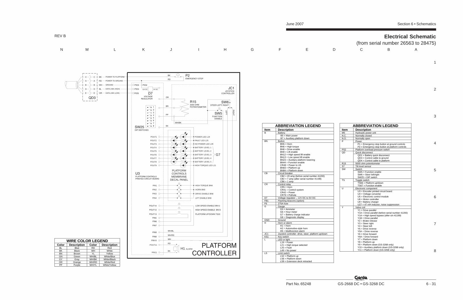
Section 6 • SchematicsJune 2007
1
2
3
4
5
6
7
8
N M L K J I H G F E D C B A
Part No. 65248 GS-2668 DC • GS-3268 DC 6 - 31
Electrical Schematic(from serial number 26563 to 28475)
REV B
PLATFORMCONTROLLER
PIN8
PIN10
PIN9
H1 ALARM
POUT11
PIN11
RD +
-BK
WH/BK
P2EMERGENCY STOP
BK
RD
1
2
3
4
8
5
7
6
SW25DIP SWITCHES
PIO3 PIO2
PIO5
PIO4 5V DC12V DC
D7VOLTAGE
REGULATOR
DATA LINK (LOW)
DATA LINK (HIGH)
GROUND
POWER TO GROUND
POWER TO PLATFORMBK
A A RD
C C
WHB B
BLD D
ORE E
QD3
JC1JOYSTICK
CONTROLLER
SW6STEER LEFT/ RIGHT
LE
FT
RIG
HTSW5
FUNCTIONENABLE
R155000 OHMPOTENTIOMETER
OR
BR
PP
HORN BN5
DRIVE ENABLE BN8
HIGH TORQUE BN6PIN1
PIN2
PIN3
LIFT ENABLE BN9PIN4
POWER LED L19
HIGH TORQUE LED L21
POUT4
POUT2
POUT3
FAULT LED L25
POUT5
POUT6
POUT7
POUT9
POUT8
NO POWER LED L49
POUT1
BATTERY LEVEL 1
BATTERY LEVEL 2
BATTERY LEVEL 3
BATTERY LEVEL 4
BATTERY LEVEL 5
G7
PLATFORMCONTROLSMEMBRANE
DECAL PANEL
BK
WH/BL
WH/RD
WH
LOW SPEED ENABLE BN12
HIGH SPEED ENABLE BN13
PIN5
PIN6
PLATFORM UP/DOWN TS20
PIN7
U3PLATFORM CONTROLSPRINTED CIRCUIT BOARD
POUT10
POUT12
POUT13
ABBREVIATION LEGENDItem Description
BatteryB B5 = Main power B7 = Auxiliary platform downButtonBN
BN5 = HornBN6 = High torqueBN8 = Drive enableBN9 = Lift enableBN12 = High speed lift enableBN13 = Low speed lift enableBN23 = Auxiliary platform loweringBN44 = Function enableCR48 = Power to U5BN83 = Platform upBN84 = Platform down
Circuit breakerCBCB2 = 20 amp (before serial number 41200)CB2 = 7 amp (after serial number 41199)CB6 = 1 amp
Control relayCRCR5 = HornCR41 = Control systemCR42 = PowerCR79 = Pothole
D7 Voltage regulator – 12V DC to 5V DCFB1 Flashing beacons (option)F6 275A fuse
GaugeGG5 = AmmeterG6 = Hour meterG7 = Battery charge indicatorG8 = Diagnostic display
GND GroundHorn or alarmH
H1 = HornH2 = Automotive-style hornH5 = Multifunction alarm
JC1 Joystick controller- drive, steer, platform up/downKS1 Key switch
LED or lightLL19 = PowerL21 = High torque selectedL25 = FaultL49 = No power
Limit switchLSLS2 = Platform upLS6 = Platform downLS9 = Extension deck retracted
ABBREVIATION LEGENDItem DescriptionM5 Hydraulic power unitN.C. Normally closedN.O. Normally open
PowerPP1 = Emergency stop button at ground controlsP2 = Emergency stop button at platform controls
PS2 Platform overload pressure switchQuick disconnectQD
QD1 = Battery quick disconnectQD3 = Control cable to groundQD4 = Control cable to platform
R15 5000 ohm potentiometerS7 Tilt level sensor
SwitchSWSW5 = Function enableSW6 = Steer left/rightSW25 = DIP switch
Toggle switchTSTS66 = Platform up/downTS67 = Function enable
Electronic componentUU3 = Encoder printed circuit boardU4 = Voltage converterU5 = Electronic control moduleU6 = Motor controllerU9 = Battery chargerU27 = 47 mH inductor, noise suppression
Valve coilYY1 = Drive parallelY1A = Drive parallel (before serial number 41200)Y1A = High speed bypass (after s/n 41199)Y1B = Drive parallelY2 = Brake releaseY3 = Steer rightY4 = Steer leftY5 = Drive reverseY5A = Drive reverseY6 = Drive forwardY6A = Drive forwardY7 = Platform downY8 = Platform upY9 = Platform down (GS-3268 only)Y10 = Auxiliary platform down (GS-3268 only)Y11 = Platform down (GS-3268 only)
WIRE COLOR LEGENDColor Description Color Description
BL Blue RD RedBK Black WH WhiteBN Brown YL YellowGN Green WH/BL White/BlueGY Gray WH/BK White/BlackOR Orange WH/RD White/RedPP Purple WH/YL White/Yellow

June 2007 Section 6 • Schematics
6 - 32
Electrical Schematic(from serial number 26563 to 28475)
6 - 31

Section 6 • SchematicsJune 2007
6 - 33 6 - 34

Section 6 • Schematics June 2007
1
2
3
4
5
6
7
8
A B C D E F G H I J K L M N
6 - 34 GS-2668 DC • GS-3268 DC Part No. 65248
Electrical Schematic(from serial number 28476 to 33850)
REV B
BR
RD WH
GND
Y3STEERRIGHT
Y8PLATFORM
UP
Y4STEER
LEFT
J1
-C1
/C4
IN
OUTOUT OUT
IN
J4
-C5
H5MULTI-
FUNCTIONALARM
OUT OUT IN
J2
-B1
2
J2
-B1
0
J2
-A6
OUT
J1
-C7
,8
J1
-A2
J1
-A1
J1
-A3
Y6DRIVE
FORWARDLEFT
Y2BRAKE
RELEASE
OUT OUT
J1
-A4
J1
-A5
Y6ADRIVE
FORWARDRIGHT
Y5DRIVE
REVERSELEFT
OUT OUT
J1
-A6
J1
-A7
Y5ADRIVE
REVERSERIGHT
OUT
J1
-A8
Y1BPARALLEL
DRIVE 3
Y1APARALLEL
DRIVE 2
OUT OUT
J1
-A11
J1
-A1
2
Y1PARALLEL
DRIVE 1
Y9PLATFORM
DOWN(GS-3268 ONLY)
OUT
J1
-A9
OUT
J1
-A1
0
J1
-C11
/C1
2
U5ELECTRONIC CONTROL MODULE
S7TILT LEVEL
SENSOR
BN23AUXILIARY
DOWN(GS-3268 ONLY)
B7EMERGENCY
DOWNBATTERY
(GS-3268 ONLY) -
+
PLATFORMCONTROL
B
T2
B
GROUNDCONTROL
KS1KEY SWITCH
CB61A
CIRCUITBREAKER
K5K6
K4
8587
8630
8587
8630
8587
8630
IN IN IN INOUTOUT
UP
DO
WN
J2
-A1
J2
-A2
J3
-A2
J3
-A1
J2
-A5
J2
-C1
/C1
0
TS67FUNCTION
ENABLESWITCH
TS66UP/DOWN
SWITCH
LS6DOWN
LIMITSWITCH
N.C.
LS2UP
LIMITSWITCH
(GS-3268 ONLY)
N.C.
P1EMERGENCYSTOP
B58-6VBATTERY
GND
F6275A FUSE
U6 MOTOR
CONTROLLER
B+
3A2
M-
B- 1
U9BATTERYCHARGER
G5AMMETER
M5MOTOR A1
D1
M5
AC INPUT
QD1 -( )
QD1 +( )
OUT
Y7PLATFORM
DOWN
+
-
-
+
+-
-+
++
-
--
-+
+
IN
J3
-A3
LS9EXTENSION
DECKRETRACTED
LIMIT SWITCH
N.C.
CB220ACIRCUITBREAKER
U2747 mH
INDUCTOR,NOISE
SUPPRESSION
G6HOUR
METER
CR5HORN RELAY(H2 OPTION)
H2
HORN(OPTION)
AUTOMOTIVE-STYLE
J2-B11
J4-A6
OUT
IN
J1-B1 OUT
FB
FB
FB
(OPTION)
FLASHINGBEACONS
K4
J2-B9 OUT
1
2
3
CR42POWERRELAY
CR41CONTROLSYSTEMRELAY
G8DIAGNOSTIC
DISPLAY
IN INOUT
J3
-B4
J3
-A4
J3
-A5
DA
TA
LIN
K-
DA
TA
LIN
K+
GN
DF
RO
MJO
YS
TIC
K
QD4
A A
C C
B B
D D
RD
WH
BL
BK
OR E E
ES0132H
INVERTER(OPTION)
8587
86
K4
30
+-U13
INVERTER
CR101INVERTER
RELAY
F980A
FUSE
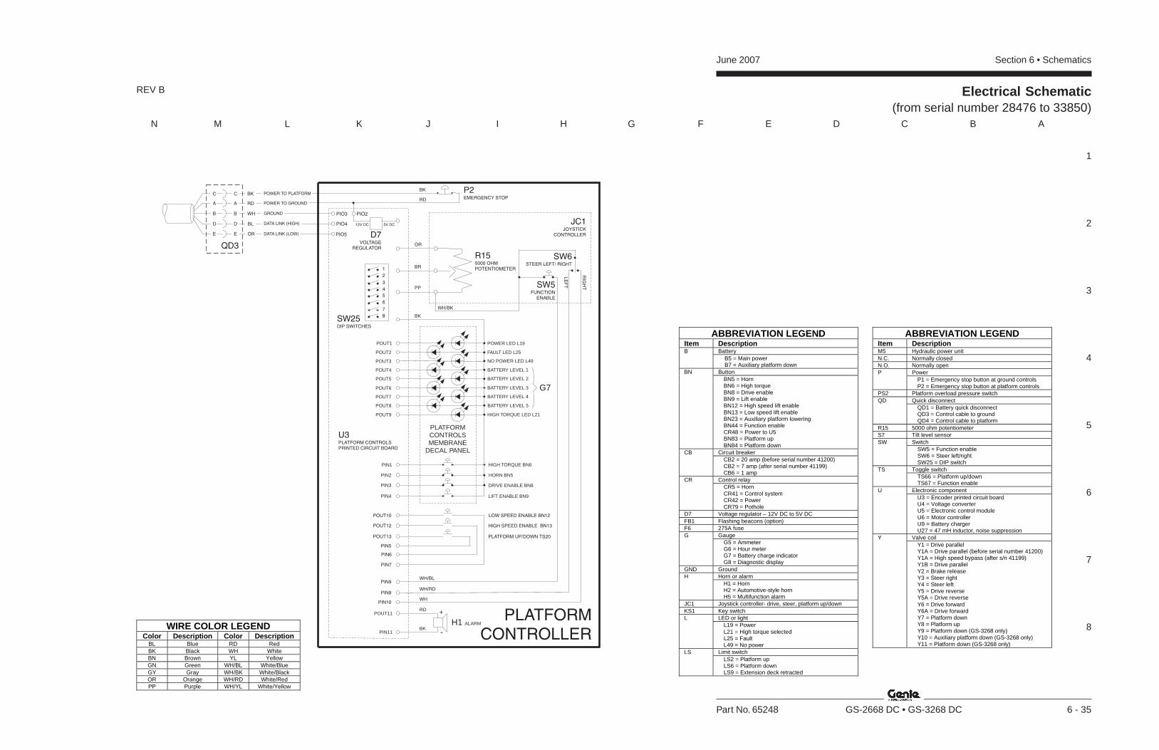
Section 6 • SchematicsJune 2007
1
2
3
4
5
6
7
8
N M L K J I H G F E D C B A
Part No. 65248 GS-2668 DC • GS-3268 DC 6 - 35
Electrical Schematic(from serial number 28476 to 33850)
REV B
WIRE COLOR LEGENDColor Description Color Description
BL Blue RD RedBK Black WH WhiteBN Brown YL YellowGN Green WH/BL White/BlueGY Gray WH/BK White/BlackOR Orange WH/RD White/RedPP Purple WH/YL White/Yellow
ABBREVIATION LEGENDItem Description
BatteryB B5 = Main power B7 = Auxiliary platform downButtonBN
BN5 = HornBN6 = High torqueBN8 = Drive enableBN9 = Lift enableBN12 = High speed lift enableBN13 = Low speed lift enableBN23 = Auxiliary platform loweringBN44 = Function enableCR48 = Power to U5BN83 = Platform upBN84 = Platform down
Circuit breakerCBCB2 = 20 amp (before serial number 41200)CB2 = 7 amp (after serial number 41199)CB6 = 1 amp
Control relayCRCR5 = HornCR41 = Control systemCR42 = PowerCR79 = Pothole
D7 Voltage regulator – 12V DC to 5V DCFB1 Flashing beacons (option)F6 275A fuse
GaugeGG5 = AmmeterG6 = Hour meterG7 = Battery charge indicatorG8 = Diagnostic display
GND GroundHorn or alarmH
H1 = HornH2 = Automotive-style hornH5 = Multifunction alarm
JC1 Joystick controller- drive, steer, platform up/downKS1 Key switch
LED or lightLL19 = PowerL21 = High torque selectedL25 = FaultL49 = No power
Limit switchLSLS2 = Platform upLS6 = Platform downLS9 = Extension deck retracted
ABBREVIATION LEGENDItem DescriptionM5 Hydraulic power unitN.C. Normally closedN.O. Normally open
PowerPP1 = Emergency stop button at ground controlsP2 = Emergency stop button at platform controls
PS2 Platform overload pressure switchQuick disconnectQD
QD1 = Battery quick disconnectQD3 = Control cable to groundQD4 = Control cable to platform
R15 5000 ohm potentiometerS7 Tilt level sensor
SwitchSWSW5 = Function enableSW6 = Steer left/rightSW25 = DIP switch
Toggle switchTSTS66 = Platform up/downTS67 = Function enable
Electronic componentUU3 = Encoder printed circuit boardU4 = Voltage converterU5 = Electronic control moduleU6 = Motor controllerU9 = Battery chargerU27 = 47 mH inductor, noise suppression
Valve coilYY1 = Drive parallelY1A = Drive parallel (before serial number 41200)Y1A = High speed bypass (after s/n 41199)Y1B = Drive parallelY2 = Brake releaseY3 = Steer rightY4 = Steer leftY5 = Drive reverseY5A = Drive reverseY6 = Drive forwardY6A = Drive forwardY7 = Platform downY8 = Platform upY9 = Platform down (GS-3268 only)Y10 = Auxiliary platform down (GS-3268 only)Y11 = Platform down (GS-3268 only)
PLATFORMCONTROLLER
PIN8
PIN10
PIN9
H1 ALARM
POUT11
PIN11
RD +
-BK
WH/BK
P2EMERGENCY STOP
BK
RD
1
2
3
4
8
5
7
6
SW25DIP SWITCHES
PIO3 PIO2
PIO5
PIO4 5V DC12V DC
D7VOLTAGE
REGULATOR
DATA LINK (LOW)
DATA LINK (HIGH)
GROUND
POWER TO GROUND
POWER TO PLATFORMBK
A A RD
C C
WHB B
BLD D
ORE E
QD3
JC1JOYSTICK
CONTROLLER
SW6STEER LEFT/ RIGHT
LE
FT
RIG
HTSW5
FUNCTIONENABLE
R155000 OHMPOTENTIOMETER
OR
BR
PP
HORN BN5
DRIVE ENABLE BN8
HIGH TORQUE BN6PIN1
PIN2
PIN3
LIFT ENABLE BN9PIN4
POWER LED L19
HIGH TORQUE LED L21
POUT4
POUT2
POUT3
FAULT LED L25
POUT5
POUT6
POUT7
POUT9
POUT8
NO POWER LED L49
POUT1
BATTERY LEVEL 1
BATTERY LEVEL 2
BATTERY LEVEL 3
BATTERY LEVEL 4
BATTERY LEVEL 5
G7
PLATFORMCONTROLSMEMBRANE
DECAL PANEL
BK
WH/BL
WH/RD
WH
LOW SPEED ENABLE BN12
HIGH SPEED ENABLE BN13
PIN5
PIN6
PLATFORM UP/DOWN TS20
PIN7
U3PLATFORM CONTROLSPRINTED CIRCUIT BOARD
POUT10
POUT12
POUT13

June 2007 Section 6 • Schematics
6 - 36
Electrical Schematic(from serial number 28476 to 33850)
6 - 35

Section 6 • SchematicsJune 2007
6 - 37 6 - 38
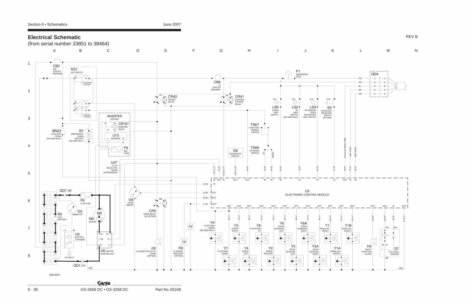
Section 6 • Schematics June 2007
1
2
3
4
5
6
7
8
A B C D E F G H I J K L M N
6 - 38 GS-2668 DC • GS-3268 DC Part No. 65248
Electrical Schematic(from serial number 33851 to 38464)
REV B
BR
RD WH
GND
Y3STEERRIGHT
Y8PLATFORM
UP
Y4STEER
LEFT
J1
-C1
/C4
IN
OUTOUT OUT
IN
J4
-C5
H5MULTI-
FUNCTIONALARM
OUT OUT IN
J2
-B1
2
J2
-B1
0
J2
-A6
OUT
J1
-C7
,8
J1
-A2
J1
-A1
J1
-A3
Y6DRIVE
FORWARDLEFT
Y2BRAKE
RELEASE
OUT OUT
J1
-A4
J1
-A5
Y6ADRIVE
FORWARDRIGHT
Y5DRIVE
REVERSELEFT
OUT OUT
J1
-A6
J1
-A7
Y5ADRIVE
REVERSERIGHT
OUT
J1
-A8
Y1BPARALLEL
DRIVE 3
Y1APARALLEL
DRIVE 2
OUT OUT
J1
-A11
J1
-A1
2
Y1PARALLEL
DRIVE 1
Y9PLATFORM
DOWN(GS-3268 ONLY)
OUT
J1
-A9
OUT
J1
-A1
0
J1
-C11
/C1
2
U5ELECTRONIC CONTROL MODULE
S7TILT LEVEL
SENSOR
BN23AUXILIARY
DOWN(GS-3268 ONLY)
B7EMERGENCY
DOWNBATTERY
(GS-3268 ONLY) -
+
PLATFORMCONTROL
B
T2
B
GROUNDCONTROL
KS1KEY SWITCH
CB61A
CIRCUITBREAKER
K5K6
K4
8587
8630
8587
8630
8587
8630
IN IN IN INOUTOUT
UP
DO
WN
J2
-A1
J2
-A2
J3
-A2
J3
-A1
J2
-A5
J2
-C1
/C1
0
TS67FUNCTION
ENABLESWITCH
TS66UP/DOWN
SWITCH
LS6DOWN
LIMITSWITCH
N.C.
LS2UP
LIMITSWITCH
(GS-3268 ONLY)
N.C.
P1EMERGENCYSTOP
B58-6VBATTERY
GND
F6275A FUSE
U6 MOTOR
CONTROLLER
B+
3A2
M-
B- 1
U9BATTERYCHARGER
G5AMMETER
M5MOTOR A1
D1
M5
AC INPUT
QD1 -( )
QD1 +( )
OUT
Y7PLATFORM
DOWN
+
-
-
+
+-
-+
++
-
--
-+
+
IN
J3
-A3
LS9EXTENSION
DECKRETRACTED
LIMIT SWITCH
N.C.
CB220ACIRCUITBREAKER
U2747 mH
INDUCTOR,NOISE
SUPPRESSION
G6HOUR
METER
CR5HORN RELAY(H2 OPTION)
H2
HORN(OPTION)
AUTOMOTIVE-STYLE
J2-B11
J4-A6
OUT
IN
J1-B1 OUT
FB
FB
FB
(OPTION)
FLASHINGBEACONS
K4
J2-B9 OUT
1
2
3
IN
J2
-A7
N.O.
S5OVERLOADPRESSURE
SWITCH(OPTION)
CR42POWERRELAY
CR41CONTROLSYSTEMRELAY
G8DIAGNOSTIC
DISPLAY
IN INOUT
J3
-B4
J3
-A4
J3
-A5
DA
TA
LIN
K-
DA
TA
LIN
K+
GN
DF
RO
MJO
YS
TIC
K
QD4
A A
C C
B B
D D
RD
WH
BL
BK
OR E E
ES0132H1
INVERTER(OPTION)
8587
86
K4
30
+-U13
INVERTER
CR101INVERTER
RELAY
F980A
FUSE

Section 6 • SchematicsJune 2007
1
2
3
4
5
6
7
8
N M L K J I H G F E D C B A
Part No. 65248 GS-2668 DC • GS-3268 DC 6 - 39
Electrical Schematic(from serial number 33851 to 38464)
REV B
ABBREVIATION LEGENDItem Description
BatteryB B5 = Main power B7 = Auxiliary platform downButtonBN
BN5 = HornBN6 = High torqueBN8 = Drive enableBN9 = Lift enableBN12 = High speed lift enableBN13 = Low speed lift enableBN23 = Auxiliary platform loweringBN44 = Function enableCR48 = Power to U5BN83 = Platform upBN84 = Platform down
Circuit breakerCBCB2 = 20 amp (before serial number 41200)CB2 = 7 amp (after serial number 41199)CB6 = 1 amp
Control relayCRCR5 = HornCR41 = Control systemCR42 = PowerCR79 = Pothole
D7 Voltage regulator – 12V DC to 5V DCFB1 Flashing beacons (option)F6 275A fuse
GaugeGG5 = AmmeterG6 = Hour meterG7 = Battery charge indicatorG8 = Diagnostic display
GND GroundHorn or alarmH
H1 = HornH2 = Automotive-style hornH5 = Multifunction alarm
JC1 Joystick controller- drive, steer, platform up/downKS1 Key switch
LED or lightLL19 = PowerL21 = High torque selectedL25 = FaultL49 = No power
Limit switchLSLS2 = Platform upLS6 = Platform downLS9 = Extension deck retracted
ABBREVIATION LEGENDItem DescriptionM5 Hydraulic power unitN.C. Normally closedN.O. Normally open
PowerPP1 = Emergency stop button at ground controlsP2 = Emergency stop button at platform controls
PS2 Platform overload pressure switchQuick disconnectQD
QD1 = Battery quick disconnectQD3 = Control cable to groundQD4 = Control cable to platform
R15 5000 ohm potentiometerS7 Tilt level sensor
SwitchSWSW5 = Function enableSW6 = Steer left/rightSW25 = DIP switch
Toggle switchTSTS66 = Platform up/downTS67 = Function enable
Electronic componentUU3 = Encoder printed circuit boardU4 = Voltage converterU5 = Electronic control moduleU6 = Motor controllerU9 = Battery chargerU27 = 47 mH inductor, noise suppression
Valve coilYY1 = Drive parallelY1A = Drive parallel (before serial number 41200)Y1A = High speed bypass (after s/n 41199)Y1B = Drive parallelY2 = Brake releaseY3 = Steer rightY4 = Steer leftY5 = Drive reverseY5A = Drive reverseY6 = Drive forwardY6A = Drive forwardY7 = Platform downY8 = Platform upY9 = Platform down (GS-3268 only)Y10 = Auxiliary platform down (GS-3268 only)Y11 = Platform down (GS-3268 only)
WIRE COLOR LEGENDColor Description Color Description
BL Blue RD RedBK Black WH WhiteBN Brown YL YellowGN Green WH/BL White/BlueGY Gray WH/BK White/BlackOR Orange WH/RD White/RedPP Purple WH/YL White/Yellow
PLATFORMCONTROLLER
PIN8
PIN10
PIN9
H1 ALARM
POUT11
PIN11
RD +
-BK
WH/BK
P2EMERGENCY STOP
BK
RD
1
2
3
4
8
5
7
6
SW25DIP SWITCHES
PIO3 PIO2
PIO5
PIO4 5V DC12V DC
D7VOLTAGE
REGULATOR
DATA LINK (LOW)
DATA LINK (HIGH)
GROUND
POWER TO GROUND
POWER TO PLATFORMBK
A A RD
C C
WHB B
BLD D
ORE E
QD3
JC1JOYSTICK
CONTROLLER
SW6STEER LEFT/ RIGHT
LE
FT
RIG
HTSW5
FUNCTIONENABLE
R155000 OHMPOTENTIOMETER
OR
BR
PP
HORN BN5
DRIVE ENABLE BN8
HIGH TORQUE BN6PIN1
PIN2
PIN3
LIFT ENABLE BN9PIN4
POWER LED L19
HIGH TORQUE LED L21
POUT4
POUT2
POUT3
FAULT LED L25
POUT5
POUT6
POUT7
POUT9
POUT8
NO POWER LED L49
POUT1
BATTERY LEVEL 1
BATTERY LEVEL 2
BATTERY LEVEL 3
BATTERY LEVEL 4
BATTERY LEVEL 5
G7
PLATFORMCONTROLSMEMBRANE
DECAL PANEL
BK
WH/BL
WH/RD
WH
LOW SPEED ENABLE BN12
HIGH SPEED ENABLE BN13
PIN5
PIN6
PLATFORM UP/DOWN TS20
PIN7
U3PLATFORM CONTROLSPRINTED CIRCUIT BOARD
POUT10
POUT12
POUT13

June 2007 Section 6 • Schematics
6 - 40
Electrical Schematic(from serial number 33851 to 38464)
6 - 39

Section 6 • SchematicsJune 2007
6 - 41 6 - 42
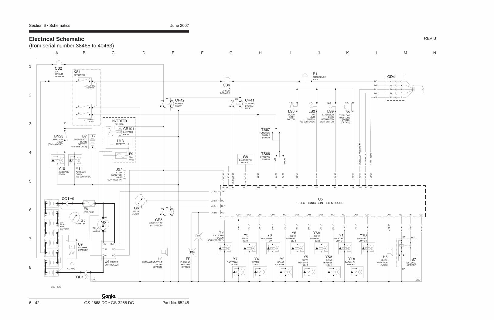
Section 6 • Schematics June 2007
1
2
3
4
5
6
7
8
A B C D E F G H I J K L M N
6 - 42 GS-2668 DC • GS-3268 DC Part No. 65248
Electrical Schematic(from serial number 38465 to 40463)
REV B
BR
RD WH
GND
Y3STEERRIGHT
Y8PLATFORM
UP
Y4STEER
LEFT
J1
-C1
/C4
IN IN INOUT
OUTOUT OUT
IN
J4
-C5
H5MULTI-
FUNCTIONALARM
OUT OUT IN
J2
-B1
2
J2
-B1
0
J2
-A6
OUT
J1
-C7
,8
J1
-A2
J1
-A1
J1
-A3
Y6DRIVE
FORWARDLEFT
Y2BRAKE
RELEASE
OUT OUT
J1
-A4
J1
-A5
Y6ADRIVE
FORWARDRIGHT
Y5DRIVE
REVERSELEFT
OUT OUT
J1
-A6
J1
-A7
Y5ADRIVE
REVERSERIGHT
OUT
J1
-A8
Y1BPARALLEL
DRIVE 3
Y1APARALLEL
DRIVE 2
OUT OUT
J1
-A11
J1
-A1
2
Y1PARALLEL
DRIVE 1
Y9PLATFORM
DOWN(GS-3268 ONLY)
OUT
J1
-A9
OUT
J1
-A1
0
J1
-C11
/C1
2
J3
-B4
J3
-A4
J3
-A5
U5ELECTRONIC CONTROL MODULE
S7TILT LEVEL
SENSOR
BN23AUXILIARY
DOWN(GS-3268 ONLY)
B7EMERGENCY
DOWNBATTERY
(GS-3268 ONLY) -
+
PLATFORMCONTROL
B
T2
B
GROUNDCONTROL
KS1KEY SWITCH
CB61A
CIRCUITBREAKER
K5K6
K4
8587
8630
8587
8630
8587
8630
IN IN IN INOUTOUT
UP
DO
WN
J2
-A1
J2
-A2
J3
-A2
J3
-A1
J2
-A5
J2
-C1
/C1
0
TS67FUNCTION
ENABLESWITCH
TS66UP/DOWN
SWITCH
LS6DOWN
LIMITSWITCH
N.C.
LS2UP
LIMITSWITCH
(GS-3268 ONLY)
N.C.
P1EMERGENCYSTOP
B58-6VBATTERY
GND
F6275A FUSE
U6 MOTOR
CONTROLLER
B+
3A2
M-
B- 1
U9BATTERYCHARGER
G5AMMETER
M5MOTOR A1
D1
M5
AC INPUT
QD1 -( )
QD1 +( )
OUT
Y7PLATFORM
DOWN
DA
TA
LIN
K-
DA
TA
LIN
K+
GN
DF
RO
MJO
YS
TIC
K
+
-
-
+
+-
-+
++
-
--
-+
+
IN
J3
-A3
LS9EXTENSION
DECKRETRACTED
LIMIT SWITCH
N.C.
CB220ACIRCUITBREAKER
U2747 mH
INDUCTOR,NOISE
SUPPRESSION
G6HOUR
METER
CR5HORN RELAY(H2 OPTION)
H2
HORN(OPTION)
AUTOMOTIVE-STYLE
J2-B11
J4-A6
OUT
IN
J1-B1 OUT
FB
FB
FB
(OPTION)
FLASHINGBEACONS
K4
J2-B9 OUT
1
2
3
IN
J2
-A7
S5OVERLOADPRESSURE
SWITCH(OPTION)
N.O.
Y11AUXILIARYDOWN(GS-3268 ONLY)
Y10AUXILIARYDOWN
CR42POWERRELAY
CR41CONTROLSYSTEMRELAY
G8DIAGNOSTIC
DISPLAY
QD4
A A
C C
B B
D D
RD
WH
BL
BK
OR E E
ES0132K
INVERTER(OPTION)
8587
86
K4
30
+-U13
INVERTER
CR101INVERTER
RELAY
F980A
FUSE
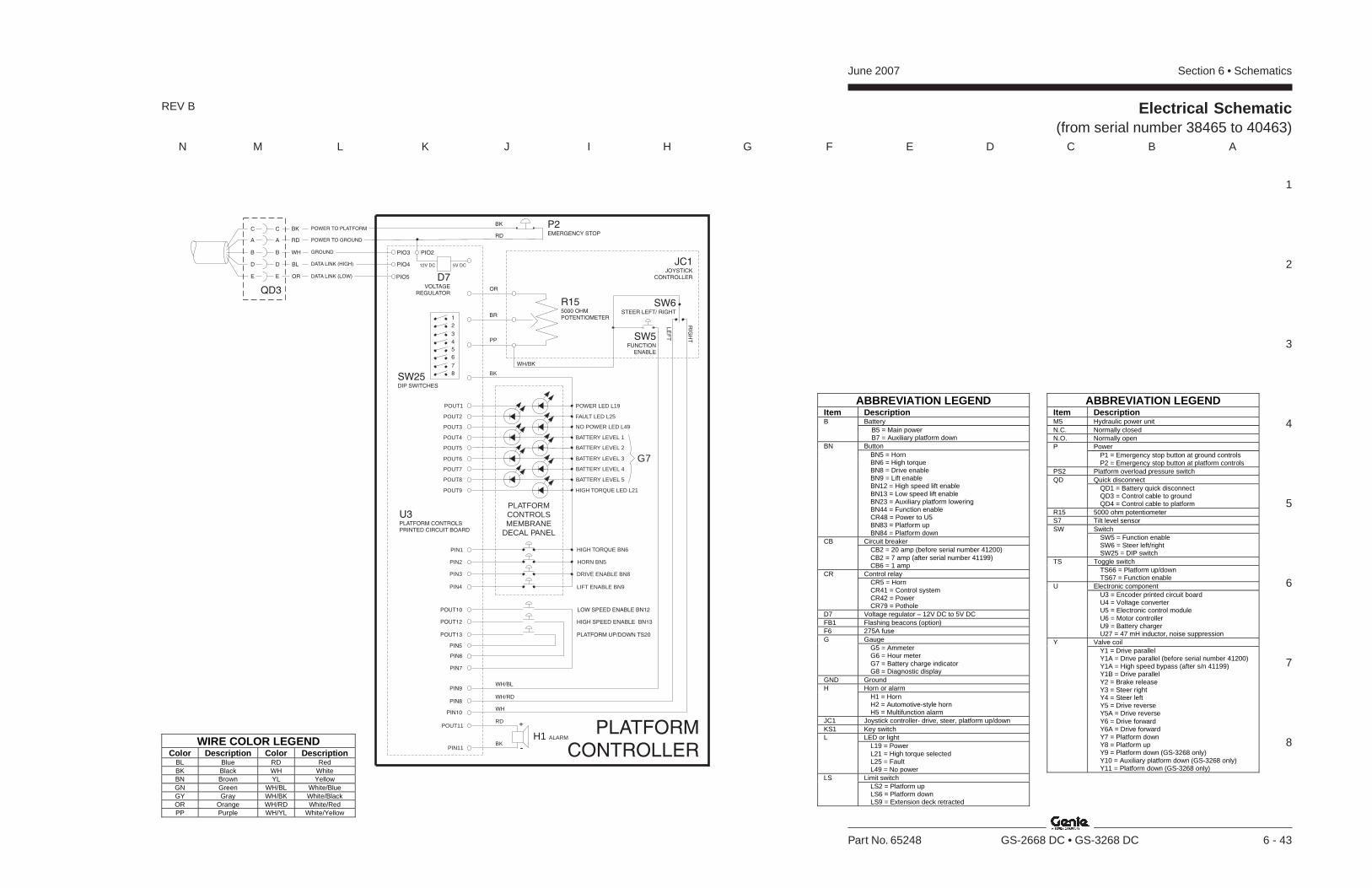
Section 6 • SchematicsJune 2007
1
2
3
4
5
6
7
8
N M L K J I H G F E D C B A
Part No. 65248 GS-2668 DC • GS-3268 DC 6 - 43
Electrical Schematic(from serial number 38465 to 40463)
REV B
ABBREVIATION LEGENDItem Description
BatteryB B5 = Main power B7 = Auxiliary platform downButtonBN
BN5 = HornBN6 = High torqueBN8 = Drive enableBN9 = Lift enableBN12 = High speed lift enableBN13 = Low speed lift enableBN23 = Auxiliary platform loweringBN44 = Function enableCR48 = Power to U5BN83 = Platform upBN84 = Platform down
Circuit breakerCBCB2 = 20 amp (before serial number 41200)CB2 = 7 amp (after serial number 41199)CB6 = 1 amp
Control relayCRCR5 = HornCR41 = Control systemCR42 = PowerCR79 = Pothole
D7 Voltage regulator – 12V DC to 5V DCFB1 Flashing beacons (option)F6 275A fuse
GaugeGG5 = AmmeterG6 = Hour meterG7 = Battery charge indicatorG8 = Diagnostic display
GND GroundHorn or alarmH
H1 = HornH2 = Automotive-style hornH5 = Multifunction alarm
JC1 Joystick controller- drive, steer, platform up/downKS1 Key switch
LED or lightLL19 = PowerL21 = High torque selectedL25 = FaultL49 = No power
Limit switchLSLS2 = Platform upLS6 = Platform downLS9 = Extension deck retracted
ABBREVIATION LEGENDItem DescriptionM5 Hydraulic power unitN.C. Normally closedN.O. Normally open
PowerPP1 = Emergency stop button at ground controlsP2 = Emergency stop button at platform controls
PS2 Platform overload pressure switchQuick disconnectQD
QD1 = Battery quick disconnectQD3 = Control cable to groundQD4 = Control cable to platform
R15 5000 ohm potentiometerS7 Tilt level sensor
SwitchSWSW5 = Function enableSW6 = Steer left/rightSW25 = DIP switch
Toggle switchTSTS66 = Platform up/downTS67 = Function enable
Electronic componentUU3 = Encoder printed circuit boardU4 = Voltage converterU5 = Electronic control moduleU6 = Motor controllerU9 = Battery chargerU27 = 47 mH inductor, noise suppression
Valve coilYY1 = Drive parallelY1A = Drive parallel (before serial number 41200)Y1A = High speed bypass (after s/n 41199)Y1B = Drive parallelY2 = Brake releaseY3 = Steer rightY4 = Steer leftY5 = Drive reverseY5A = Drive reverseY6 = Drive forwardY6A = Drive forwardY7 = Platform downY8 = Platform upY9 = Platform down (GS-3268 only)Y10 = Auxiliary platform down (GS-3268 only)Y11 = Platform down (GS-3268 only)
WIRE COLOR LEGENDColor Description Color Description
BL Blue RD RedBK Black WH WhiteBN Brown YL YellowGN Green WH/BL White/BlueGY Gray WH/BK White/BlackOR Orange WH/RD White/RedPP Purple WH/YL White/Yellow
PLATFORMCONTROLLER
PIN8
PIN10
PIN9
H1 ALARM
POUT11
PIN11
RD +
-BK
WH/BK
P2EMERGENCY STOP
BK
RD
1
2
3
4
8
5
7
6
SW25DIP SWITCHES
PIO3 PIO2
PIO5
PIO4 5V DC12V DC
D7VOLTAGE
REGULATOR
DATA LINK (LOW)
DATA LINK (HIGH)
GROUND
POWER TO GROUND
POWER TO PLATFORMBK
A A RD
C C
WHB B
BLD D
ORE E
QD3
JC1JOYSTICK
CONTROLLER
SW6STEER LEFT/ RIGHT
LE
FT
RIG
HTSW5
FUNCTIONENABLE
R155000 OHMPOTENTIOMETER
OR
BR
PP
HORN BN5
DRIVE ENABLE BN8
HIGH TORQUE BN6PIN1
PIN2
PIN3
LIFT ENABLE BN9PIN4
POWER LED L19
HIGH TORQUE LED L21
POUT4
POUT2
POUT3
FAULT LED L25
POUT5
POUT6
POUT7
POUT9
POUT8
NO POWER LED L49
POUT1
BATTERY LEVEL 1
BATTERY LEVEL 2
BATTERY LEVEL 3
BATTERY LEVEL 4
BATTERY LEVEL 5
G7
PLATFORMCONTROLSMEMBRANE
DECAL PANEL
BK
WH/BL
WH/RD
WH
LOW SPEED ENABLE BN12
HIGH SPEED ENABLE BN13
PIN5
PIN6
PLATFORM UP/DOWN TS20
PIN7
U3PLATFORM CONTROLSPRINTED CIRCUIT BOARD
POUT10
POUT12
POUT13

June 2007 Section 6 • Schematics
6 - 44
Electrical Schematic(from serial number 38465 to 40463)
6 - 43

Section 6 • SchematicsJune 2007
6 - 45 6 - 46
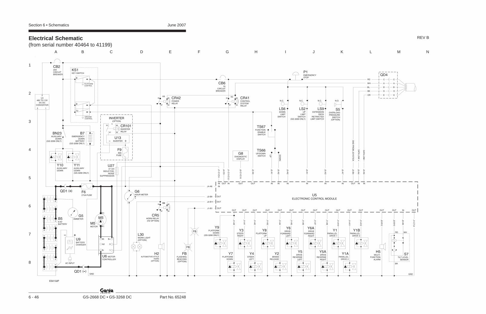
Section 6 • Schematics June 2007
1
2
3
4
5
6
7
8
A B C D E F G H I J K L M N
6 - 46 GS-2668 DC • GS-3268 DC Part No. 65248
Electrical Schematic(from serial number 40464 to 41199)
REV B
BR
RD WH
GND
Y3STEERRIGHT
Y8PLATFORM
UP
Y4STEER
LEFT
J1
-C1
/C4
IN
OUTOUT OUT
IN
J4
-C5
H5MULTI-
FUNCTIONALARM
OUT OUT IN
J2
-B1
2
J2
-B1
0
J2
-A6
OUT
J1
-C7
,8
J1
-A2
J1
-A1
J1
-A3
Y6DRIVE
FORWARDLEFT
Y2BRAKE
RELEASE
OUT OUT
J1
-A4
J1
-A5
Y6ADRIVE
FORWARDRIGHT
Y5DRIVE
REVERSELEFT
OUT OUT
J1
-A6
J1
-A7
Y5ADRIVE
REVERSERIGHT
OUT
J1
-A8
Y1BPARALLEL
DRIVE 3
Y1APARALLEL
DRIVE 2
OUT OUT
J1
-A11
J1
-A1
2
Y1PARALLEL
DRIVE 1
Y9PLATFORM
DOWN(GS-3268 ONLY)
OUT
J1
-A9
OUT
J1
-A1
0
J1
-C11
/C1
2
U5ELECTRONIC CONTROL MODULE
S7TILT LEVEL
SENSOR
BN23AUXILIARY
DOWN(GS-3268 ONLY)
B7EMERGENCY
DOWNBATTERY
(GS-3268 ONLY) -
+
PLATFORMCONTROL
B
T2
B
GROUNDCONTROL
KS1KEY SWITCH
CB61A
CIRCUITBREAKER
K5K6
K4
8587
8630
8587
8630
8587
8630
IN IN IN INOUTOUT
UP
DO
WN
J2
-A1
J2
-A2
J3
-A2
J3
-A1
J2
-A5
J2
-C1
/C1
0
TS67FUNCTION
ENABLESWITCH
TS66UP/DOWN
SWITCH
LS6DOWN
LIMITSWITCH
N.C.
LS2UP
LIMITSWITCH
(GS-3268 ONLY)
N.C.
P1EMERGENCYSTOP
B58-6VBATTERY
GND
U6 MOTOR
CONTROLLER
B+
3A2
M-
B- 1
U9BATTERYCHARGER
G5AMMETER
M5MOTOR A1
D1
M5
AC INPUT
QD1 -( )
OUT
Y7PLATFORM
DOWN
+
-
-
+
+-
-+
++
-
--
-+
+
IN
J3
-A3
LS9EXTENSION
DECKRETRACTED
LIMIT SWITCH
N.C.
CB220ACIRCUITBREAKER
U2747 mH
INDUCTOR,NOISE
SUPPRESSION
CR5HORN RELAY(H2 OPTION)
H2AUTOMOTIVE-STYLE
HORN(OPTION)
J2-B11
J4-A6
OUT
IN
J1-B1 OUT
FB
FB
FB
(OPTION)
FLASHINGBEACONS
K4
J2-B9 OUT3
IN
J2
-A7
N.O.
Y11AUXILIARYDOWN(GS-3268 ONLY)
Y10AUXILIARYDOWN
3 1
2
U448V TO 13V
DC-DCCONVERTER
QD1 +( ) F6275A FUSE
S5OVERLOADPRESSURE
SWITCH(OPTION)
CR42POWERRELAY
CR41CONTROLSYSTEMRELAY
G8DIAGNOSTIC
DISPLAY
IN INOUT
J3
-B4
J3
-A4
J3
-A5
DA
TA
LIN
K-
DA
TA
LIN
K+
GN
DF
RO
MJO
YS
TIC
K
QD4
A A
C C
B B
D D
RD
WH
BL
BK
OR E E
G6HOUR METER
L30WORK LIGHT(OPTION)
2
1
ES0132P
INVERTER(OPTION)
8587
86
K4
30
+-U13
INVERTER
CR101INVERTER
RELAY
F980A
FUSE
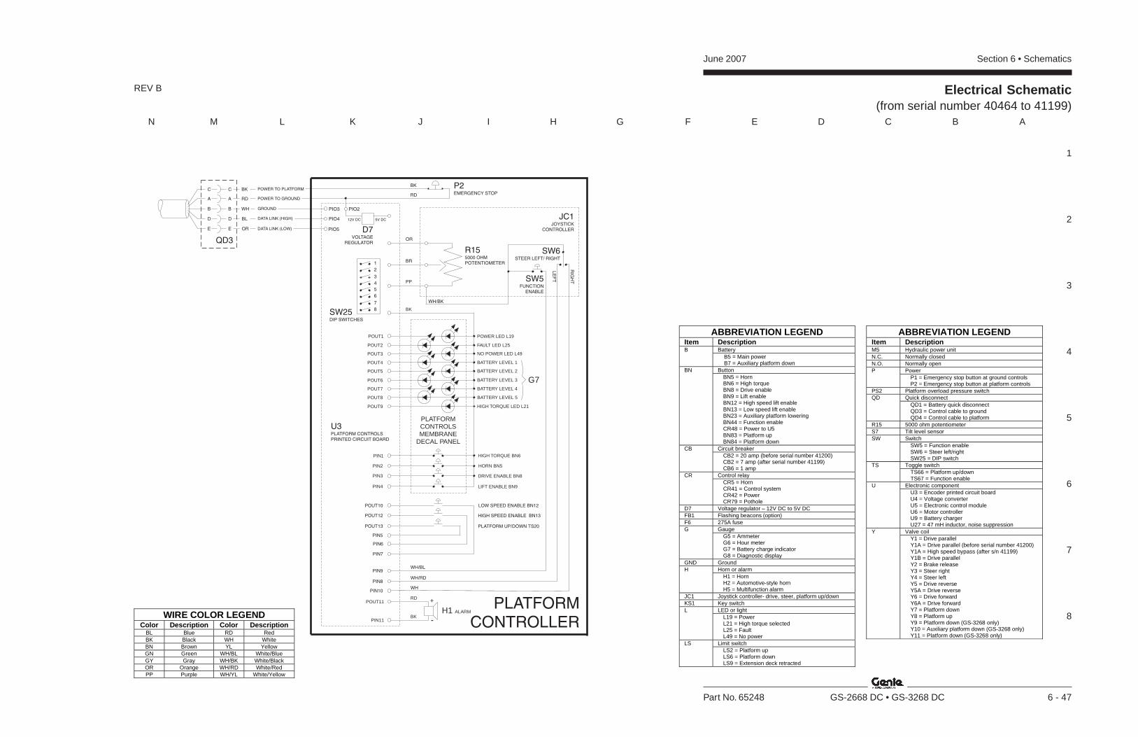
Section 6 • SchematicsJune 2007
1
2
3
4
5
6
7
8
N M L K J I H G F E D C B A
Part No. 65248 GS-2668 DC • GS-3268 DC 6 - 47
Electrical Schematic(from serial number 40464 to 41199)
REV B
ABBREVIATION LEGEND Item Description
Battery B B5 = Main power
B7 = Auxiliary platform down Button BN BN5 = Horn BN6 = High torque BN8 = Drive enable BN9 = Lift enable BN12 = High speed lift enable BN13 = Low speed lift enable BN23 = Auxiliary platform lowering BN44 = Function enable CR48 = Power to U5 BN83 = Platform up BN84 = Platform down Circuit breaker CB CB2 = 20 amp (before serial number 41200) CB2 = 7 amp (after serial number 41199) CB6 = 1 amp Control relay CR CR5 = Horn CR41 = Control system CR42 = Power CR79 = Pothole
D7 Voltage regulator – 12V DC to 5V DC FB1 Flashing beacons (option) F6 275A fuse
Gauge G G5 = Ammeter G6 = Hour meter G7 = Battery charge indicator G8 = Diagnostic display
GND Ground Horn or alarm H H1 = Horn H2 = Automotive-style horn H5 = Multifunction alarm
JC1 Joystick controller- drive, steer, platform up/down KS1 Key switch
LED or light L L19 = Power L21 = High torque selected L25 = Fault L49 = No power Limit switch LS LS2 = Platform up LS6 = Platform down LS9 = Extension deck retracted
ABBREVIATION LEGEND Item Description M5 Hydraulic power unit N.C. Normally closed N.O. Normally open
Power P P1 = Emergency stop button at ground controls P2 = Emergency stop button at platform controls
PS2 Platform overload pressure switch Quick disconnect QD QD1 = Battery quick disconnect QD3 = Control cable to ground QD4 = Control cable to platform
R15 5000 ohm potentiometer S7 Tilt level sensor
Switch SW SW5 = Function enable SW6 = Steer left/right SW25 = DIP switch Toggle switch TS TS66 = Platform up/down TS67 = Function enable Electronic component U U3 = Encoder printed circuit board U4 = Voltage converter U5 = Electronic control module U6 = Motor controller U9 = Battery charger U27 = 47 mH inductor, noise suppression Valve coil Y Y1 = Drive parallel Y1A = Drive parallel (before serial number 41200) Y1A = High speed bypass (after s/n 41199) Y1B = Drive parallel Y2 = Brake release Y3 = Steer right Y4 = Steer left Y5 = Drive reverse Y5A = Drive reverse Y6 = Drive forward Y6A = Drive forward Y7 = Platform down Y8 = Platform up Y9 = Platform down (GS-3268 only) Y10 = Auxiliary platform down (GS-3268 only) Y11 = Platform down (GS-3268 only)
WIRE COLOR LEGEND Color Description Color Description
BL Blue RD Red BK Black WH White BN Brown YL Yellow GN Green WH/BL White/Blue GY Gray WH/BK White/Black OR Orange WH/RD White/Red PP Purple WH/YL White/Yellow
PLATFORMCONTROLLER
PIN8
PIN10
PIN9
H1 ALARM
POUT11
PIN11
RD +
-BK
WH/BK
P2EMERGENCY STOP
BK
RD
1
2
3
4
8
5
7
6
SW25DIP SWITCHES
PIO3 PIO2
PIO5
PIO4 5V DC12V DC
D7VOLTAGE
REGULATOR
DATA LINK (LOW)
DATA LINK (HIGH)
GROUND
POWER TO GROUND
POWER TO PLATFORMBK
A A RD
C C
WHB B
BLD D
ORE E
QD3
JC1JOYSTICK
CONTROLLER
SW6STEER LEFT/ RIGHT
LE
FT
RIG
HTSW5
FUNCTIONENABLE
R155000 OHMPOTENTIOMETER
OR
BR
PP
HORN BN5
DRIVE ENABLE BN8
HIGH TORQUE BN6PIN1
PIN2
PIN3
LIFT ENABLE BN9PIN4
POWER LED L19
HIGH TORQUE LED L21
POUT4
POUT2
POUT3
FAULT LED L25
POUT5
POUT6
POUT7
POUT9
POUT8
NO POWER LED L49
POUT1
BATTERY LEVEL 1
BATTERY LEVEL 2
BATTERY LEVEL 3
BATTERY LEVEL 4
BATTERY LEVEL 5
G7
PLATFORMCONTROLSMEMBRANE
DECAL PANEL
BK
WH/BL
WH/RD
WH
LOW SPEED ENABLE BN12
HIGH SPEED ENABLE BN13
PIN5
PIN6
PLATFORM UP/DOWN TS20
PIN7
U3PLATFORM CONTROLSPRINTED CIRCUIT BOARD
POUT10
POUT12
POUT13

June 2007 Section 6 • Schematics
6 - 48
Electrical Schematic(from serial number 40464 to 41199)
6 - 47

Section 6 • SchematicsJune 2007
6 - 49 6 - 50
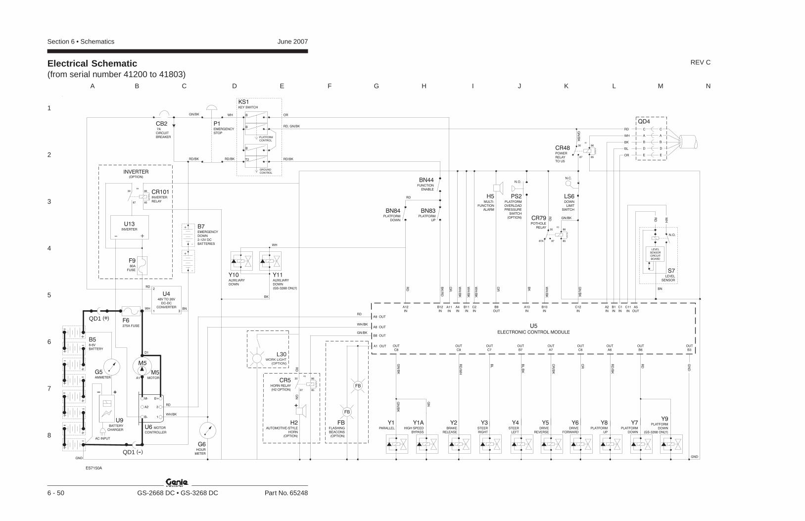
Section 6 • Schematics June 2007
1
2
3
4
5
6
7
8
A B C D E F G H I J K L M N
6 - 50 GS-2668 DC • GS-3268 DC Part No. 65248
Electrical Schematic(from serial number 41200 to 41803)
REV C
Y8PLATFORM
UP
GND
G6HOUR
METER
Y2BRAKE
RELEASE
Y3STEER
RIGHT
Y4STEER
LEFT
Y5DRIVE
REVERSE
Y6DRIVE
FORWARD
Y1PARALLEL
LS6DOWN
LIMIT
SWITCH
A6
OUT
IN
A11
IN IN
BN83PLATFORM
UP
BN44FUNCTION
ENABLE
BN84PLATFORM
DOWN
A12 B12
U5
ELECTRONIC CONTROL MODULE
IN IN IN
A2 B1 C1
C9 C7 B7 A7 C6
OUT OUT OUT OUT OUT
GN
D
B3
OUT
C8
OUT
IN
C12
A1 OUT
FB
FB
FB
(OPTION)
FLASHING
BEACONS
Y7PLATFORM
DOWN
B6
OUT
Y9PLATFORM
DOWN
(GS-3268 ONLY)
Y1AHIGH SPEED
BYPASS
H5MULTI-
FUNCTION
ALARM
OUT
B9
IN
A10
IN
C2
IN
A4
IN
B11
N.O.
PS2PLATFORM
OVERLOAD
PRESSURE
SWITCH
(OPTION)
IN OUT
C11 A5
RD
WH
BN
N.O.
S7LEVEL
SENSOR
LEVEL
SENSOR
CIRCUIT
BOARD
P1EMERGENCY
STOP
CB27A
CIRCUIT
BREAKER
B58-6V
BATTERY
GND
U6 MOTOR
CONTROLLER
B+
3A2
M-
B- 1
G5AMMETER
M5MOTORA1
D1
M5
QD1 -( )
+
-
-
+
+-
-+
++
-
--
-+
+
QD1 +( ) F6275A FUSE
U448V TO 26V
DC-DC
CONVERTER
1
2
3
--
++
PLATFORM
CONTROL
T2
B
B
GROUND
CONTROL
KS1KEY SWITCH
B
IN
B10
CR79POTHOLE
RELAY
85
8630
8787A
K3B7EMERGENCY
DOWN
2-12V DC
BATTERIES
B8 OUT
A8 OUT
A9 OUT
RD, GN/BK
OR
WH
WHGN/BK
RD/BK RD/BK
WH/BK
RD
RD/BK
BN
85
8630
87
CR48POWER
RELAY
TO U5
K1
GN
/BK
RD
QD4
A A
C C
B B
D D
E E
RD GN/BK
RD
WH/BK
GN/BK
WH
/BK
BK
OR
OR
WH
/BK
WH
/BK
WH
/BK
BK
/RD
RD
GN
/BK
RD
RD
/BK
OR
OR
/BK
BL/B
K
BL
RD
/WH
GN
/BK
GN
GN
/BK
RD
WH
BK
BL
OR
N.C.
WH
BK
Y11AUXILIARY
DOWN
(GS-3268 ONLY)
Y10AUXILIARY
DOWN
CR5HORN RELAY
(H2 OPTION) 8587
86
K2
30
H2AUTOMOTIVE-STYLE
HORN
(OPTION)
RD
GN
L30WORK LIGHT
(OPTION)
ES7150A
U9BATTERY
CHARGER
AC INPUT
INVERTER(OPTION)
8587
86
K4
30
+-
U13INVERTER
CR101INVERTER
RELAY
F980A
FUSE
RD
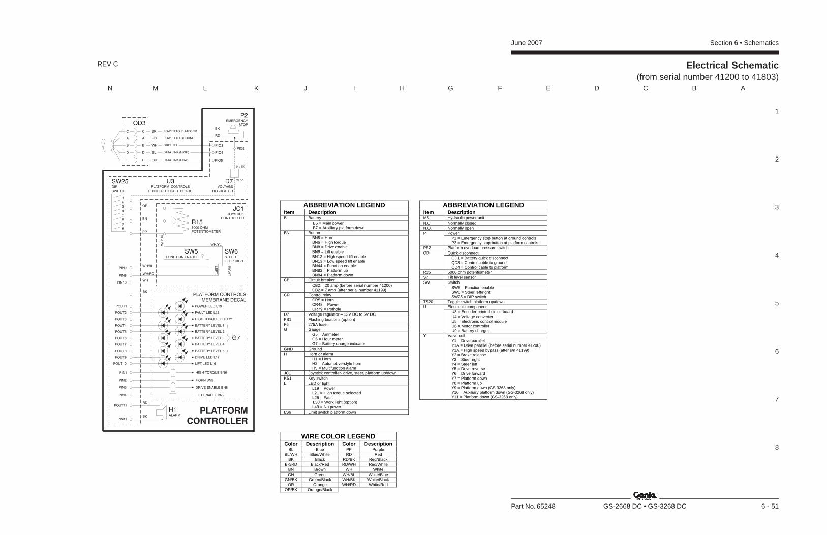
Section 6 • SchematicsJune 2007
1
2
3
4
5
6
7
8
N M L K J I H G F E D C B A
Part No. 65248 GS-2668 DC • GS-3268 DC 6 - 51
Electrical Schematic(from serial number 41200 to 41803)
REV C
ABBREVIATION LEGEND Item Description
Battery B B5 = Main power
B7 = Auxiliary platform down Button BN BN5 = Horn BN6 = High torque BN8 = Drive enable BN9 = Lift enable BN12 = High speed lift enable BN13 = Low speed lift enable BN44 = Function enable BN83 = Platform up BN84 = Platform down Circuit breaker CB CB2 = 20 amp (before serial number 41200) CB2 = 7 amp (after serial number 41199) Control relay CR CR5 = Horn CR48 = Power CR79 = Pothole
D7 Voltage regulator – 12V DC to 5V DC FB1 Flashing beacons (option) F6 275A fuse
Gauge G G5 = Ammeter G6 = Hour meter G7 = Battery charge indicator
GND Ground Horn or alarm H H1 = Horn H2 = Automotive-style horn H5 = Multifunction alarm
JC1 Joystick controller- drive, steer, platform up/down KS1 Key switch
LED or light L L19 = Power L21 = High torque selected L25 = Fault L30 = Work light (option) L49 = No power
LS6 Limit switch platform down
ABBREVIATION LEGEND Item Description M5 Hydraulic power unit N.C. Normally closed N.O. Normally open
Power P P1 = Emergency stop button at ground controls P2 = Emergency stop button at platform controls
PS2 Platform overload pressure switch Quick disconnect QD QD1 = Battery quick disconnect QD3 = Control cable to ground QD4 = Control cable to platform
R15 5000 ohm potentiometer S7 Tilt level sensor
Switch SW SW5 = Function enable SW6 = Steer left/right SW25 = DIP switch
TS20 Toggle switch platform up/down Electronic component U U3 = Encoder printed circuit board U4 = Voltage converter U5 = Electronic control module U6 = Motor controller U9 = Battery charger Valve coil Y Y1 = Drive parallel Y1A = Drive parallel (before serial number 41200) Y1A = High speed bypass (after s/n 41199) Y2 = Brake release Y3 = Steer right Y4 = Steer left Y5 = Drive reverse Y6 = Drive forward Y7 = Platform down Y8 = Platform up Y9 = Platform down (GS-3268 only) Y10 = Auxiliary platform down (GS-3268 only) Y11 = Platform down (GS-3268 only)
WIRE COLOR LEGEND Color Description Color Description
BL Blue PP Purple BL/WH Blue/White RD Red
BK Black RD/BK Red/Black BK/RD Black/Red RD/WH Red/White
BN Brown WH White GN Green WH/BL White/Blue
GN/BK Green/Black WH/BK White/Black OR Orange WH/RD White/Red
OR/BK Orange/Black
PLATFORM
CONTROLLER
HORN BN5
DRIVE ENABLE BN8
HIGH TORQUE BN6PIN1
PIN2
PIN3
LIFT ENABLE BN9PIN4
POWER LED L19
DRIVE LED L17
LIFT LED L16
POUT4
POUT2
POUT3
FAULT LED L25
POUT5
POUT6
POUT7
POUT9
POUT8
POUT10
HIGH TORQUE LED L21
POUT1
BATTERY LEVEL 1
BATTERY LEVEL 2
BATTERY LEVEL 3
BATTERY LEVEL 4
BATTERY LEVEL 5
G7
PLATFORM CONTROLSMEMBRANE DECAL
H1ALARM
POUT11
PIN11
RD+
-BK
BK
P2EMERGENCY
STOPBK
RD
SW25DIPSWITCH
PIO3
PIO5
PIO4
DATA LINK (LOW)
DATA LINK (HIGH)
GROUND
POWER TO GROUND
POWER TO PLATFORMBK
RD
WH
BL
OR
QD3
D7VOLTAGE
REGULATOR
5V DC
24V DC
PIO2
U3PLATFORM CONTROLS
PRINTED CIRCUIT BOARD
1
2
3
4
5
6
7
8
PIN8
PIN10
PIN9WH/BL
WH/RD
WH
JC1JOYSTICK
CONTROLLER
LE
FT
RIG
HT
SW5FUNCTION ENABLE
A
C
B
D
E
A
C
B
D
E
R155000 OHMPOTENTIOMETER
WH/YLWH
/BK
SW6STEERLEFT/ RIGHT
OR
BN
PP

June 2007 Section 6 • Schematics
6 - 52
Electrical Schematic(from serial number 41200 to 41803)
6 - 51

Section 6 • SchematicsJune 2007
6 - 53 6 - 54
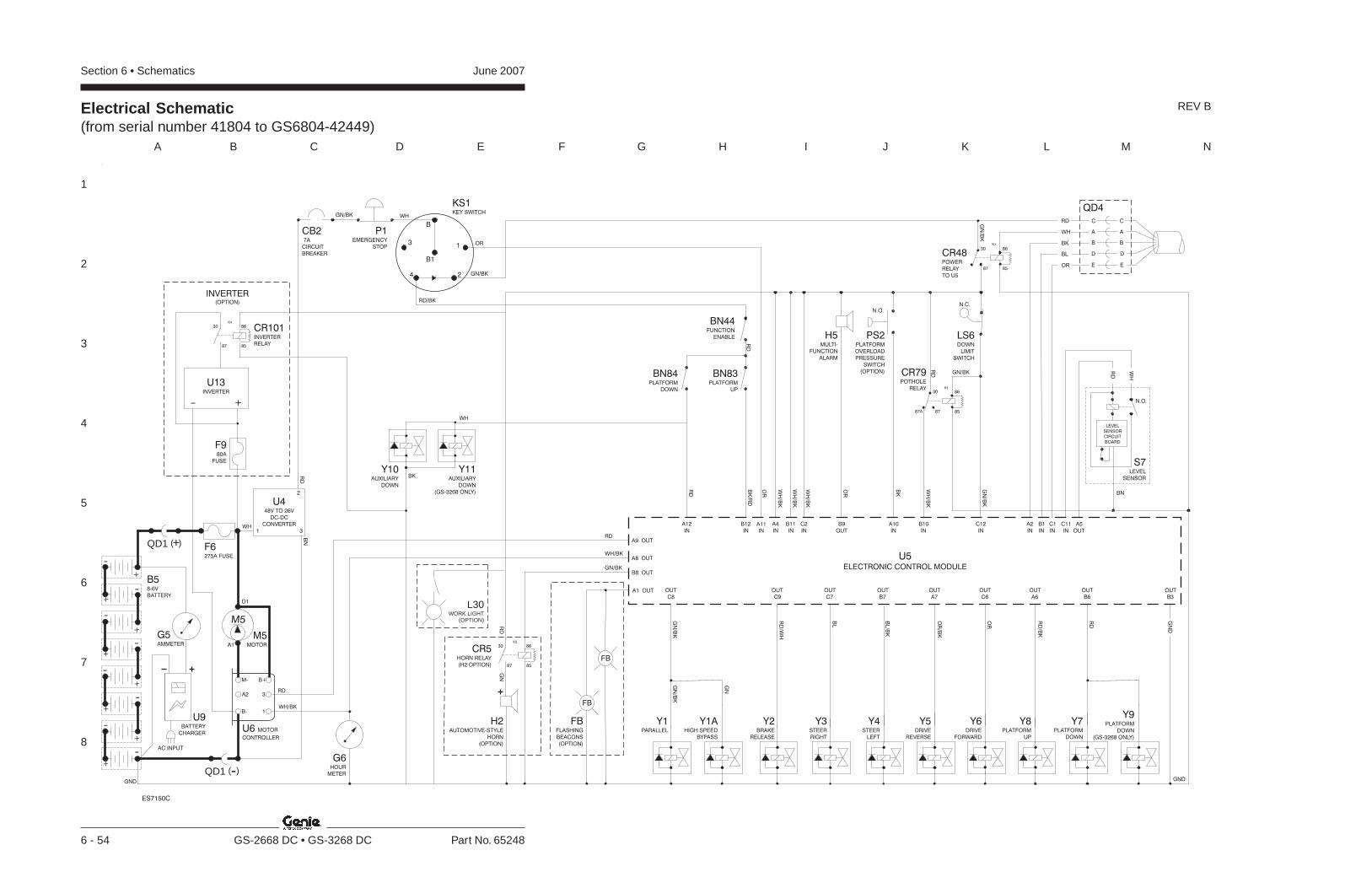
Section 6 • Schematics June 2007
1
2
3
4
5
6
7
8
A B C D E F G H I J K L M N
6 - 54 GS-2668 DC • GS-3268 DC Part No. 65248
Electrical Schematic(from serial number 41804 to GS6804-42449)
REV B
Y8PLATFORM
UP
GND
G6HOUR
METER
Y2BRAKE
RELEASE
Y3STEER
RIGHT
Y4STEER
LEFT
Y5DRIVE
REVERSE
Y6DRIVE
FORWARD
Y1PARALLEL
LS6DOWN
LIMIT
SWITCH
A6
OUT
IN
A11
IN IN
BN83PLATFORM
UP
BN44FUNCTION
ENABLE
BN84PLATFORM
DOWN
A12 B12
U5
ELECTRONIC CONTROL MODULE
IN IN IN
A2 B1 C1
C9 C7 B7 A7 C6
OUT OUT OUT OUT OUT
GN
D
B3
OUT
C8
OUT
IN
C12
A1 OUT
FB
FB
FB
(OPTION)
FLASHING
BEACONS
Y7PLATFORM
DOWN
B6
OUT
Y9PLATFORM
DOWN
(GS-3268 ONLY)
Y1AHIGH SPEED
BYPASS
H5MULTI-
FUNCTION
ALARM
OUT
B9
IN
A10
IN
C2
IN
A4
IN
B11
N.O.
PS2PLATFORM
OVERLOAD
PRESSURE
SWITCH
(OPTION)
IN OUT
C11 A5
RD
WH
BN
N.O.
S7LEVEL
SENSOR
LEVEL
SENSOR
CIRCUIT
BOARD
P1EMERGENCY
STOP
CB27A
CIRCUIT
BREAKER
KS1KEY SWITCH
B
B1
31
4 2
B58-6V
BATTERY
GND
U6 MOTOR
CONTROLLER
B+
3A2
M-
B- 1
G5AMMETER
M5MOTORA1
D1
M5
QD1 -( )
+
-
-
+
+-
-+
++
-
--
-+
+
QD1 +( ) F6275A FUSE
U448V TO 26V
DC-DC
CONVERTER
1
2
3 IN
B10
CR79POTHOLE
RELAY
85
8630
8787A
K3
B8 OUT
A8 OUT
A9 OUT
OR
WH
WHGN/BK
WH/BK
RD
RD/BK
GN/BK
RD
BN
85
8630
87
CR48POWER
RELAY
TO U5
K1
GN
/BK
RD
QD4
A A
C C
B B
D D
E E
RD
WH/BK
GN/BK
WH
/BK
BK
OR
OR
WH
/BK
WH
/BK
WH
/BK
BK
/RD
RD
RD
GN
/BK
GN/BK
RD
RD
/BK
OR
OR
/BK
BL/B
K
BL
RD
/WH
GN
/BK
GN
/BK
GN
RD
WH
BK
BL
OR
N.C.
WH
BKY11
AUXILIARY
DOWN
(GS-3268 ONLY)
Y10AUXILIARY
DOWN
CR5HORN RELAY
(H2 OPTION) 8587
86
K2
30
H2AUTOMOTIVE-STYLE
HORN
(OPTION)
RD
GN
L30WORK LIGHT
(OPTION)
ES7150C
U9BATTERY
CHARGER
AC INPUT
INVERTER(OPTION)
8587
86
K4
30
+-
U13INVERTER
CR101INVERTER
RELAY
F980A
FUSE
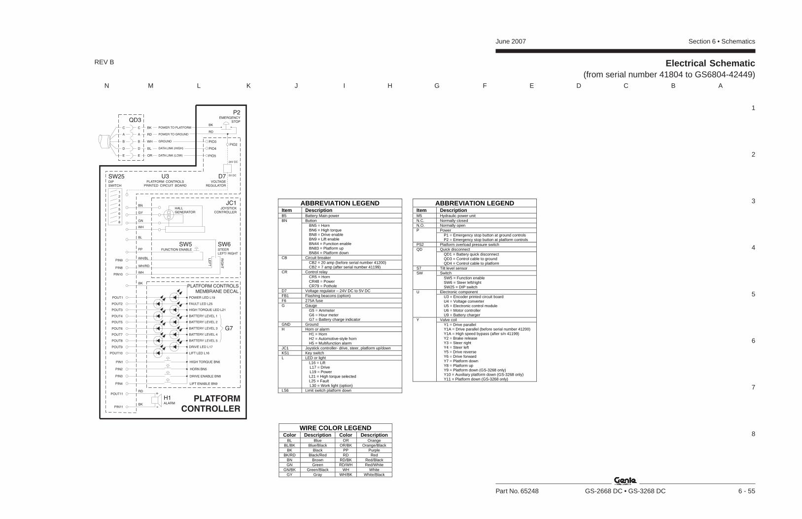
Section 6 • SchematicsJune 2007
1
2
3
4
5
6
7
8
N M L K J I H G F E D C B A
Part No. 65248 GS-2668 DC • GS-3268 DC 6 - 55
Electrical Schematic(from serial number 41804 to GS6804-42449)
REV B
ABBREVIATION LEGEND Item Description B5 Battery Main power
Button BN BN5 = Horn BN6 = High torque BN8 = Drive enable BN9 = Lift enable BN44 = Function enable BN83 = Platform up BN84 = Platform down Circuit breaker CB CB2 = 20 amp (before serial number 41200) CB2 = 7 amp (after serial number 41199) Control relay CR CR5 = Horn CR48 = Power CR79 = Pothole
D7 Voltage regulator – 24V DC to 5V DC FB1 Flashing beacons (option) F6 275A fuse
Gauge G G5 = Ammeter G6 = Hour meter G7 = Battery charge indicator
GND Ground Horn or alarm H H1 = Horn H2 = Automotive-style horn H5 = Multifunction alarm
JC1 Joystick controller- drive, steer, platform up/down KS1 Key switch
LED or light L L16 = Lift L17 = Drive L19 = Power L21 = High torque selected L25 = Fault L30 = Work light (option)
LS6 Limit switch platform down
ABBREVIATION LEGEND Item Description M5 Hydraulic power unit N.C. Normally closed N.O. Normally open
Power P P1 = Emergency stop button at ground controls P2 = Emergency stop button at platform controls
PS2 Platform overload pressure switch Quick disconnect QD QD1 = Battery quick disconnect QD3 = Control cable to ground QD4 = Control cable to platform
S7 Tilt level sensor Switch SW SW5 = Function enable SW6 = Steer left/right SW25 = DIP switch Electronic component U U3 = Encoder printed circuit board U4 = Voltage converter U5 = Electronic control module U6 = Motor controller U9 = Battery charger Valve coil Y Y1 = Drive parallel Y1A = Drive parallel (before serial number 41200) Y1A = High speed bypass (after s/n 41199) Y2 = Brake release Y3 = Steer right Y4 = Steer left Y5 = Drive reverse Y6 = Drive forward Y7 = Platform down Y8 = Platform up Y9 = Platform down (GS-3268 only) Y10 = Auxiliary platform down (GS-3268 only) Y11 = Platform down (GS-3268 only)
WIRE COLOR LEGEND Color Description Color Description
BL Blue OR Orange BL/BK Blue/Black OR/BK Orange/Black
BK Black PP Purple BK/RD Black/Red RD Red
BN Brown RD/BK Red/Black GN Green RD/WH Red/White
GN/BK Green/Black WH White GY Gray WH/BK White/Black
PLATFORM
CONTROLLER
HORN BN5
DRIVE ENABLE BN8
HIGH TORQUE BN6PIN1
PIN2
PIN3
LIFT ENABLE BN9PIN4
POWER LED L19
DRIVE LED L17
LIFT LED L16
POUT4
POUT2
POUT3
FAULT LED L25
POUT5
POUT6
POUT7
POUT9
POUT8
POUT10
HIGH TORQUE LED L21
POUT1
BATTERY LEVEL 1
BATTERY LEVEL 2
BATTERY LEVEL 3
BATTERY LEVEL 4
BATTERY LEVEL 5
G7
PLATFORM CONTROLSMEMBRANE DECAL
H1ALARM
POUT11
PIN11
RD+
-BK
BK
P2EMERGENCY
STOPBK
RD
SW25DIPSWITCH
PIO3
PIO5
PIO4
DATA LINK (LOW)
DATA LINK (HIGH)
GROUND
POWER TO GROUND
POWER TO PLATFORMBK
RD
WH
BL
OR
QD3
D7VOLTAGE
REGULATOR
5V DC
24V DC
PIO2
U3PLATFORM CONTROLS
PRINTED CIRCUIT BOARD
1
2
3
4
5
6
7
8
PIN8
PIN10
PIN9WH/BL
WH/RD
WH
JC1JOYSTICK
CONTROLLER
LE
FT
RIG
HT
SW5FUNCTION ENABLE
A
C
B
D
E
A
C
B
D
E
SW6STEERLEFT/ RIGHT
PP
BL
BN
GY
GN
WH
HALLGENERATOR

June 2007 Section 6 • Schematics
6 - 56
Electrical Schematic(from serial number 41804 to GS6804-42449)
6 - 55

Section 6 • SchematicsJune 2007
6 - 57 6 - 58
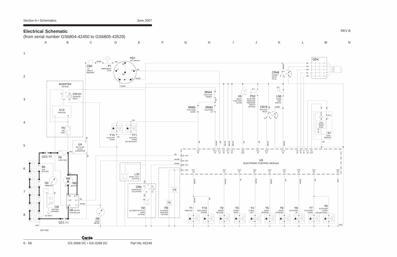
Section 6 • Schematics June 2007
1
2
3
4
5
6
7
8
A B C D E F G H I J K L M N
6 - 58 GS-2668 DC • GS-3268 DC Part No. 65248
Electrical Schematic(from serial number GS6804-42450 to GS6805-43529)
REV B
Y8PLATFORM
UP
GND
G6HOUR
METER
Y2BRAKE
RELEASE
Y3STEER
RIGHT
Y4STEER
LEFT
Y5DRIVE
REVERSE
Y6DRIVE
FORWARD
Y1PARALLEL
LS6DOWN
LIMIT
SWITCH
A6
OUT
IN
A11
IN IN
BN83PLATFORM
UP
BN44FUNCTION
ENABLE
BN84PLATFORM
DOWN
A12 B12
U5
ELECTRONIC CONTROL MODULE
IN IN IN
A2 B1 C1
C9 C7 B7 A7 C6
OUT OUT OUT OUT OUT
GN
D
B3
OUT
C8
OUT
IN
C12
A1 OUT
FB
FB
FB
(OPTION)
FLASHING
BEACONS
Y7PLATFORM
DOWN
B6
OUT
Y9PLATFORM
DOWN
(GS-3268 ONLY)
Y1AHIGH SPEED
BYPASS
RD
WH
BK
BL
OR
H5MULTI-
FUNCTION
ALARM
OUT
B9
IN
A10
IN
C2
IN
A4
IN
B11
N.O.
PS2PLATFORM
OVERLOAD
PRESSURE
SWITCH
(OPTION)
IN OUT
C11 A5
RD
WH
BN
N.O.
S7LEVEL
SENSOR
LEVEL
SENSOR
CIRCUIT
BOARD
P1EMERGENCY
STOP
CB27A
CIRCUIT
BREAKER
KS1KEY SWITCH
B
B1
31
4 2
B58-6V
BATTERY
GND
U6 MOTOR
CONTROLLER
B+
3A2
M-
B- 1
G5AMMETER
M5MOTORA1
D1
M5
QD1 -( )
+
-
-
+
+-
-+
++
-
--
-+
+
QD1 +( ) F6275A FUSE
U448V TO 26V
DC-DC
CONVERTER
1
2
3 IN
B10
CR79POTHOLE
RELAY
85
8630
8787A
K3
B8 OUT
A8 OUT
A9 OUT
OR
WH
WH
BK
WHGN/BK
WH/BK
RD
RD/BK
GN/BK
RD
BN
85
8630
87
CR48POWER
RELAY
TO U5
K1
GN
/BK
RD
Y11AUXILIARY
DOWN
(GS-3268 ONLY)
Y10AUXILIARY
DOWN
QD4
RD
WH/BK
GN/BK
WH
/BK
BK
OR
OR
WH
/BK
WH
/BK
WH
/BK
BK
/RD
RD
RD
GN
/BK
GN/BK
RD
RD
/BK
OR
OR
/BK
BL/B
K
BL
RD
/WH
GN
/BK
GN
/BK
GN
3
1
2
5
4
3
1
2
5
4
N.C.
CR5HORN RELAY
(H2 OPTION) 8587
86
K2
30
H2AUTOMOTIVE-STYLE
HORN
(OPTION)
RD
GN
L30WORK LIGHT
(OPTION)
ES7150D
U9BATTERY
CHARGER
AC INPUT
INVERTER(OPTION)
8587
86
K4
30
+-
U13INVERTER
CR101INVERTER
RELAY
F980A
FUSE

Section 6 • SchematicsJune 2007
1
2
3
4
5
6
7
8
N M L K J I H G F E D C B A
Part No. 65248 GS-2668 DC • GS-3268 DC 6 - 59
Electrical Schematic(from serial number GS6804-42450 to GS6805-43529)
REV B
ABBREVIATION LEGEND Item Description M5 Hydraulic power unit N.C. Normally closed N.O. Normally open
Power P P1 = Emergency stop button at ground controls P2 = Emergency stop button at platform controls
PS2 Platform overload pressure switch Quick disconnect QD QD1 = Battery quick disconnect QD3 = Control cable to ground QD4 = Control cable to platform
S7 Tilt level sensor Switch SW SW5 = Function enable SW6 = Steer left/right SW25 = DIP switch Electronic component U U3 = Encoder printed circuit board U4 = Voltage converter U5 = Electronic control module U6 = Motor controller U9 = Battery charger Valve coil Y Y1 = Drive parallel Y1A = Drive parallel (before serial number 41200) Y1A = High speed bypass (after s/n 41199) Y2 = Brake release Y3 = Steer right Y4 = Steer left Y5 = Drive reverse Y6 = Drive forward Y7 = Platform down Y8 = Platform up Y9 = Platform down (GS-3268 only) Y10 = Auxiliary platform down (GS-3268 only) Y11 = Platform down (GS-3268 only)
ABBREVIATION LEGEND Item Description B5 Battery Main power
Button BN BN5 = Horn BN6 = High torque BN8 = Drive enable BN9 = Lift enable BN44 = Function enable BN83 = Platform up BN84 = Platform down Circuit breaker CB CB2 = 20 amp (before serial number 41200) CB2 = 7 amp (after serial number 41199) Control relay CR CR5 = Horn CR48 = Power CR79 = Pothole
D7 Voltage regulator – 24V DC to 5V DC FB1 Flashing beacons (option) F6 275A fuse
Gauge G G5 = Ammeter G6 = Hour meter G7 = Battery charge indicator
GND Ground Horn or alarm H H1 = Horn H2 = Automotive-style horn H5 = Multifunction alarm
JC1 Joystick controller- drive, steer, platform up/down KS1 Key switch
LED or light L L16 = Lift L17 = Drive L19 = Power L21 = High torque selected L25 = Fault L30 = Work light (option)
LS6 Limit switch platform down
WIRE COLOR LEGEND Color Description Color Description
BL Blue OR Orange BL/BK Blue/Black OR/BK Orange/Black
BK Black PP Purple BK/RD Black/Red RD Red
BN Brown RD/BK Red/Black GN Green RD/WH Red/White
GN/BK Green/Black WH White GY Gray WH/BK White/Black
PLATFORM
CONTROLLER
HORN BN5
DRIVE ENABLE BN8
HIGH TORQUE BN6PIN1
PIN2
PIN3
LIFT ENABLE BN9PIN4
POWER LED L19
DRIVE LED L17
LIFT LED L16
POUT4
POUT2
POUT3
FAULT LED L25
POUT5
POUT6
POUT7
POUT9
POUT8
POUT10
HIGH TORQUE LED L21
POUT1
BATTERY LEVEL 1
BATTERY LEVEL 2
BATTERY LEVEL 3
BATTERY LEVEL 4
BATTERY LEVEL 5
G7
PLATFORM CONTROLSMEMBRANE DECAL
H1ALARM
POUT11
PIN11
RD+
-BK
BK
P2EMERGENCY
STOPBK
RD
SW25DIPSWITCH
PIO3
PIO5
PIO4
DATA LINK (LOW)
DATA LINK (HIGH)
GROUND
POWER TO GROUND
POWER TO PLATFORMBK
RD
WH
BL
OR
QD3
D7VOLTAGE
REGULATOR
5V DC
24V DC
PIO2
U3PLATFORM CONTROLS
PRINTED CIRCUIT BOARD
1
2
3
4
5
6
7
8
PIN8
PIN10
PIN9WH/BL
WH/RD
WH
JC1JOYSTICK
CONTROLLER
LE
FT
RIG
HT
SW5FUNCTION ENABLE
A
C
B
D
E
A
C
B
D
E
SW6STEERLEFT/ RIGHT
PP
BL
BN
GY
GN
WH
HALLGENERATOR
June 2007 Section 6 • Schematics
6 - 60
Electrical Schematic(from serial number GS6804-42450 to GS6805-43529)
6 - 59

Section 6 • SchematicsJune 2007
6 - 61 6 - 62
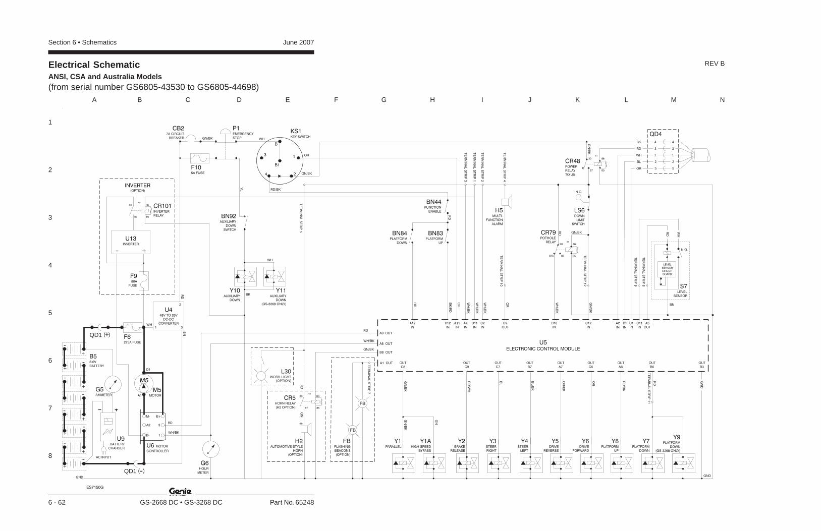
Section 6 • Schematics June 2007
1
2
3
4
5
6
7
8
A B C D E F G H I J K L M N
6 - 62 GS-2668 DC • GS-3268 DC Part No. 65248
Electrical SchematicANSI, CSA and Australia Models(from serial number GS6805-43530 to GS6805-44698)
REV B
Y8PLATFORM
UP
GND
G6HOUR
METER
Y2BRAKE
RELEASE
Y3STEER
RIGHT
Y4STEER
LEFT
Y5DRIVE
REVERSE
Y6DRIVE
FORWARD
Y1PARALLEL
LS6DOWN
LIMIT
SWITCH
A6
OUT
IN
A11
IN IN
BN83PLATFORM
UP
BN44FUNCTION
ENABLE
BN84PLATFORM
DOWN
A12 B12
U5
ELECTRONIC CONTROL MODULE
IN IN IN
A2 B1 C1
C9 C7 B7 A7 C6
OUT OUT OUT OUT OUT
GN
D
B3
OUT
C8
OUT
IN
C12
A1 OUT
FB
FB
FB
(OPTION)
FLASHING
BEACONS
Y7PLATFORM
DOWN
B6
OUT
Y9PLATFORM
DOWN
(GS-3268 ONLY)
Y1AHIGH SPEED
BYPASS
RD
WH
BK
BL
OR
H5MULTI-
FUNCTION
ALARM
OUT
B9
IN
C2
IN
A4
IN
B11
IN OUT
C11 A5
RD
WH
BN
N.O.
S7LEVEL
SENSOR
LEVEL
SENSOR
CIRCUIT
BOARD
P1EMERGENCY
STOP
CB27A CIRCUIT
BREAKER
KS1KEY SWITCH
B
B1
31
4 2
B58-6V
BATTERY
GND
U6 MOTOR
CONTROLLER
B+
3A2
M-
B- 1
G5AMMETER
M5MOTORA1
D1
M5
QD1 -( )
+
-
-
+
+-
-+
++
-
--
-+
+
QD1 +( ) F6275A FUSE
U448V TO 26V
DC-DC
CONVERTER
1
2
3 IN
B10
CR79POTHOLE
RELAY
85
8630
8787A
K3
B8 OUT
A8 OUT
A9 OUT
OR
WH
WH
BK
WHGN/BK
WH/BK
RD
RD/BK
GN/BK
RD
BN
85
8630
87
CR48POWER
RELAY
TO U5
K1
GN
/BK
RD
Y11AUXILIARY
DOWN
(GS-3268 ONLY)
Y10AUXILIARY
DOWN
QD4
RD
WH/BK
GN/BK
WH
/BK
OR
OR
WH
/BK
WH
/BK
WH
/BK
BK
/RD
RD
RD
GN
/BK
GN/BK
RD
RD
/BK
OR
OR
/BK
BL/B
K
BL
RD
/WH
GN
/BK
GN
/BK
GN
3
1
2
5
4
3
1
2
5
4
N.C.
CR5HORN RELAY
(H2 OPTION) 8587
86
K2
30
H2AUTOMOTIVE-STYLE
HORN
(OPTION)
RD
GN
L30WORK LIGHT
(OPTION)
F105A FUSE
TE
RM
INA
LS
TR
IP3
TE
RM
INA
LS
TR
IP1
TE
RM
INA
LS
TR
IP2
TE
RM
INA
LS
TR
IP4
TE
RM
INA
LS
TR
IP1
0
TE
RM
INA
LS
TR
IP1
2
TE
RM
INA
LS
TR
IP7
TE
RM
INA
LS
TR
IP1
1
TE
RM
INA
LS
TR
IP9
TE
RM
INA
LS
TR
IP8
BN92AUXILIARY
DOWN
SWITCH
ES7150G
YL
TE
RM
INA
LS
TR
IP5
INVERTER(OPTION)
8587
86
K4
30
+-
U13INVERTER
CR101INVERTER
RELAY
F980A
FUSE
U9BATTERY
CHARGER
AC INPUT
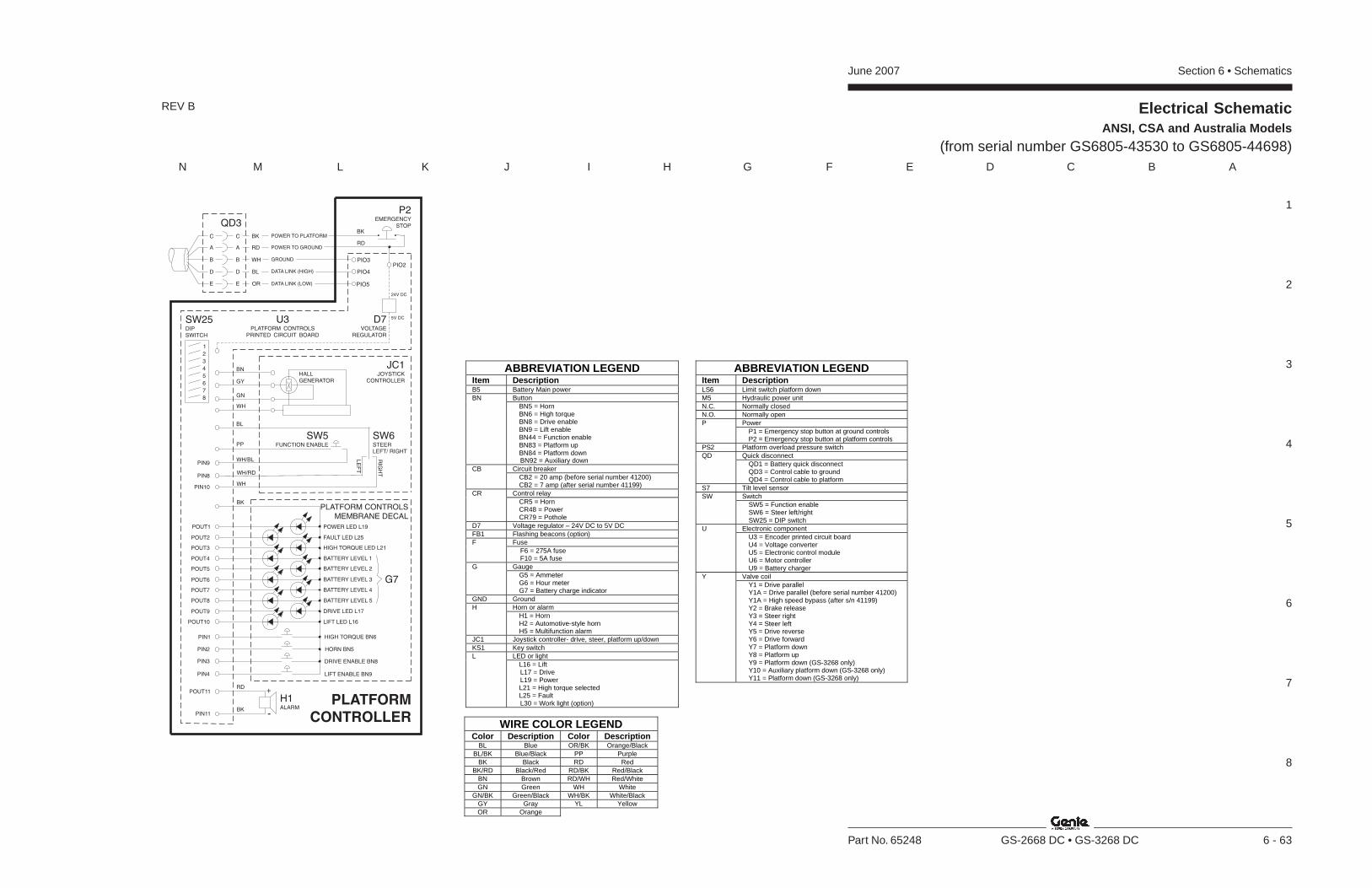
Section 6 • SchematicsJune 2007
1
2
3
4
5
6
7
8
N M L K J I H G F E D C B A
Part No. 65248 GS-2668 DC • GS-3268 DC 6 - 63
Electrical SchematicANSI, CSA and Australia Models
(from serial number GS6805-43530 to GS6805-44698)
REV B
ABBREVIATION LEGEND Item Description B5 Battery Main power
Button BN BN5 = Horn BN6 = High torque BN8 = Drive enable BN9 = Lift enable BN44 = Function enable BN83 = Platform up BN84 = Platform down BN92 = Auxiliary down Circuit breaker CB CB2 = 20 amp (before serial number 41200) CB2 = 7 amp (after serial number 41199) Control relay CR CR5 = Horn CR48 = Power CR79 = Pothole
D7 Voltage regulator – 24V DC to 5V DC FB1 Flashing beacons (option)
Fuse F F6 = 275A fuse F10 = 5A fuse Gauge G G5 = Ammeter G6 = Hour meter G7 = Battery charge indicator
GND Ground Horn or alarm H H1 = Horn H2 = Automotive-style horn H5 = Multifunction alarm
JC1 Joystick controller- drive, steer, platform up/down KS1 Key switch
LED or light L L16 = Lift L17 = Drive L19 = Power L21 = High torque selected L25 = Fault L30 = Work light (option)
ABBREVIATION LEGEND Item Description LS6 Limit switch platform down M5 Hydraulic power unit N.C. Normally closed N.O. Normally open
Power P P1 = Emergency stop button at ground controls P2 = Emergency stop button at platform controls
PS2 Platform overload pressure switch Quick disconnect QD QD1 = Battery quick disconnect QD3 = Control cable to ground QD4 = Control cable to platform
S7 Tilt level sensor Switch SW SW5 = Function enable SW6 = Steer left/right SW25 = DIP switch Electronic component U U3 = Encoder printed circuit board U4 = Voltage converter U5 = Electronic control module U6 = Motor controller U9 = Battery charger Valve coil Y Y1 = Drive parallel Y1A = Drive parallel (before serial number 41200) Y1A = High speed bypass (after s/n 41199) Y2 = Brake release Y3 = Steer right Y4 = Steer left Y5 = Drive reverse Y6 = Drive forward Y7 = Platform down Y8 = Platform up Y9 = Platform down (GS-3268 only) Y10 = Auxiliary platform down (GS-3268 only) Y11 = Platform down (GS-3268 only)
WIRE COLOR LEGEND Color Description Color Description
BL Blue OR/BK Orange/Black BL/BK Blue/Black PP Purple
BK Black RD Red BK/RD Black/Red RD/BK Red/Black
BN Brown RD/WH Red/White GN Green WH White
GN/BK Green/Black WH/BK White/Black GY Gray YL Yellow OR Orange
PLATFORM
CONTROLLER
HORN BN5
DRIVE ENABLE BN8
HIGH TORQUE BN6PIN1
PIN2
PIN3
LIFT ENABLE BN9PIN4
POWER LED L19
DRIVE LED L17
LIFT LED L16
POUT4
POUT2
POUT3
FAULT LED L25
POUT5
POUT6
POUT7
POUT9
POUT8
POUT10
HIGH TORQUE LED L21
POUT1
BATTERY LEVEL 1
BATTERY LEVEL 2
BATTERY LEVEL 3
BATTERY LEVEL 4
BATTERY LEVEL 5
G7
PLATFORM CONTROLSMEMBRANE DECAL
H1ALARM
POUT11
PIN11
RD+
-BK
BK
P2EMERGENCY
STOPBK
RD
SW25DIPSWITCH
PIO3
PIO5
PIO4
DATA LINK (LOW)
DATA LINK (HIGH)
GROUND
POWER TO GROUND
POWER TO PLATFORMBK
RD
WH
BL
OR
QD3
D7VOLTAGE
REGULATOR
5V DC
24V DC
PIO2
U3PLATFORM CONTROLS
PRINTED CIRCUIT BOARD
1
2
3
4
5
6
7
8
PIN8
PIN10
PIN9WH/BL
WH/RD
WH
JC1JOYSTICK
CONTROLLER
LE
FT
RIG
HT
SW5FUNCTION ENABLE
A
C
B
D
E
A
C
B
D
E
SW6STEERLEFT/ RIGHT
PP
BL
BN
GY
GN
WH
HALLGENERATOR
June 2007 Section 6 • Schematics
6 - 64
Electrical SchematicANSI, CSA and Australia Models
(from serial number GS6805-43530 to GS6805-44698)
6 - 63

Section 6 • SchematicsJune 2007
6 - 65 6 - 66
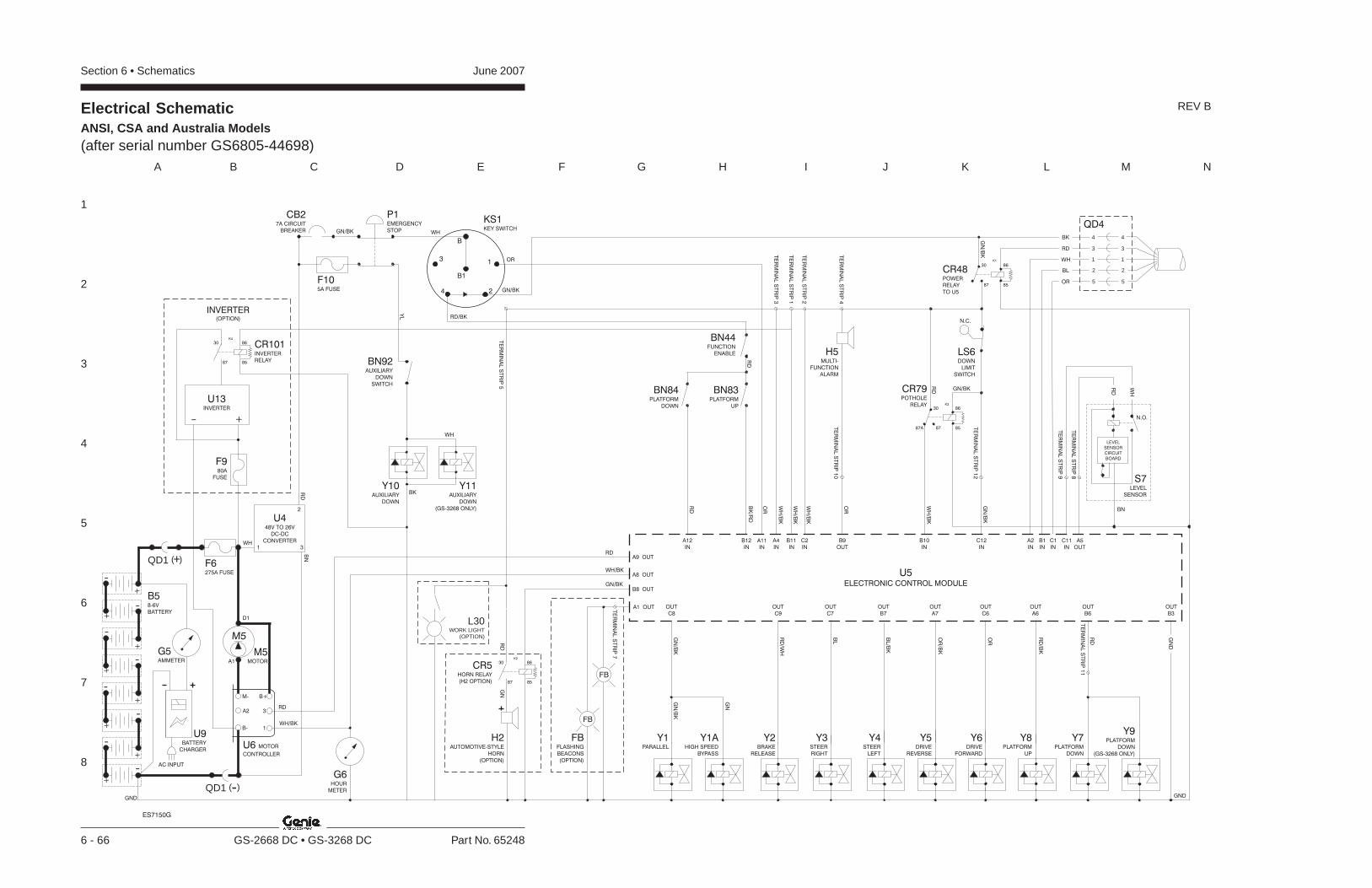
Section 6 • Schematics June 2007
1
2
3
4
5
6
7
8
A B C D E F G H I J K L M N
6 - 66 GS-2668 DC • GS-3268 DC Part No. 65248
Electrical SchematicANSI, CSA and Australia Models(after serial number GS6805-44698)
REV B
Y8PLATFORM
UP
GND
G6HOUR
METER
Y2BRAKE
RELEASE
Y3STEER
RIGHT
Y4STEER
LEFT
Y5DRIVE
REVERSE
Y6DRIVE
FORWARD
Y1PARALLEL
LS6DOWN
LIMIT
SWITCH
A6
OUT
IN
A11
IN IN
BN83PLATFORM
UP
BN44FUNCTION
ENABLE
BN84PLATFORM
DOWN
A12 B12
U5
ELECTRONIC CONTROL MODULE
IN IN IN
A2 B1 C1
C9 C7 B7 A7 C6
OUT OUT OUT OUT OUT
GN
D
B3
OUT
C8
OUT
IN
C12
A1 OUT
FB
FB
FB
(OPTION)
FLASHING
BEACONS
Y7PLATFORM
DOWN
B6
OUT
Y9PLATFORM
DOWN
(GS-3268 ONLY)
Y1AHIGH SPEED
BYPASS
RD
WH
BK
BL
OR
H5MULTI-
FUNCTION
ALARM
OUT
B9
IN
C2
IN
A4
IN
B11
IN OUT
C11 A5
RD
WH
BN
N.O.
S7LEVEL
SENSOR
LEVEL
SENSOR
CIRCUIT
BOARD
P1EMERGENCY
STOP
CB27A CIRCUIT
BREAKER
KS1KEY SWITCH
B
B1
31
4 2
B58-6V
BATTERY
GND
U6 MOTOR
CONTROLLER
B+
3A2
M-
B- 1
G5AMMETER
M5MOTORA1
D1
M5
QD1 -( )
+
-
-
+
+-
-+
++
-
--
-+
+
QD1 +( ) F6275A FUSE
U448V TO 26V
DC-DC
CONVERTER
1
2
3 IN
B10
CR79POTHOLE
RELAY
85
8630
8787A
K3
B8 OUT
A8 OUT
A9 OUT
OR
WH
WH
BK
WHGN/BK
WH/BK
RD
RD/BK
GN/BK
RD
BN
85
8630
87
CR48POWER
RELAY
TO U5
K1
GN
/BK
RD
Y11AUXILIARY
DOWN
(GS-3268 ONLY)
Y10AUXILIARY
DOWN
QD4
RD
WH/BK
GN/BK
WH
/BK
OR
OR
WH
/BK
WH
/BK
WH
/BK
BK
/RD
RD
RD
GN
/BK
GN/BK
RD
RD
/BK
OR
OR
/BK
BL/B
K
BL
RD
/WH
GN
/BK
GN
/BK
GN
3
1
2
5
4
3
1
2
5
4
N.C.
CR5HORN RELAY
(H2 OPTION) 8587
86
K2
30
H2AUTOMOTIVE-STYLE
HORN
(OPTION)
RD
GN
L30WORK LIGHT
(OPTION)
F105A FUSE
TE
RM
INA
LS
TR
IP3
TE
RM
INA
LS
TR
IP1
TE
RM
INA
LS
TR
IP2
TE
RM
INA
LS
TR
IP4
TE
RM
INA
LS
TR
IP1
0
TE
RM
INA
LS
TR
IP1
2
TE
RM
INA
LS
TR
IP7
TE
RM
INA
LS
TR
IP1
1
TE
RM
INA
LS
TR
IP9
TE
RM
INA
LS
TR
IP8
BN92AUXILIARY
DOWN
SWITCH
ES7150G
YL
U9BATTERY
CHARGER
AC INPUT
INVERTER(OPTION)
8587
86
K4
30
+-
U13INVERTER
CR101INVERTER
RELAY
F980A
FUSE
TE
RM
INA
LS
TR
IP5
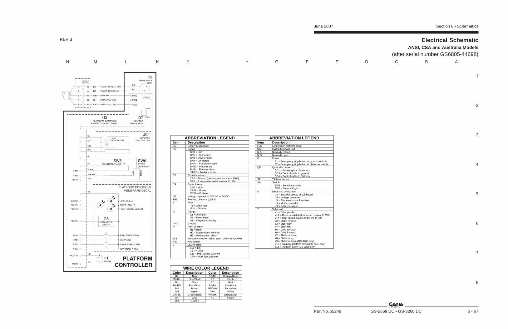
Section 6 • SchematicsJune 2007
1
2
3
4
5
6
7
8
N M L K J I H G F E D C B A
Part No. 65248 GS-2668 DC • GS-3268 DC 6 - 67
Electrical SchematicANSI, CSA and Australia Models
(after serial number GS6805-44698)
REV B
ABBREVIATION LEGEND Item Description B5 Battery Main power
Button BN BN5 = Horn BN6 = High torque BN8 = Drive enable BN9 = Lift enable BN44 = Function enable BN83 = Platform up BN84 = Platform down BN92 = Auxiliary down Circuit breaker CB CB2 = 20 amp (before serial number 41200) CB2 = 7 amp (after serial number 41199) Control relay CR CR5 = Horn CR48 = Power CR79 = Pothole
D7 Voltage regulator – 24V DC to 5V DC FB1 Flashing beacons (option)
Fuse F F6 = 275A fuse F10 = 5A fuse Gauge G G5 = Ammeter G6 = Hour meter G8 = Diagnostic display
GND Ground Horn or alarm H H1 = Horn H2 = Automotive-style horn H5 = Multifunction alarm
JC1 Joystick controller- drive, steer, platform up/down KS1 Key switch
LED or light L L16 = Lift L17 = Drive L21 = High torque selected L30 = Work light (option)
ABBREVIATION LEGEND Item Description LS6 Limit switch platform down M5 Hydraulic power unit N.C. Normally closed N.O. Normally open
Power P P1 = Emergency stop button at ground controls P2 = Emergency stop button at platform controls Quick disconnect QD QD1 = Battery quick disconnect QD3 = Control cable to ground QD4 = Control cable to platform
S7 Tilt level sensor Switch SW SW5 = Function enable SW6 = Steer left/right Electronic component U U3 = Encoder printed circuit board U4 = Voltage converter U5 = Electronic control module U6 = Motor controller U9 = Battery charger Valve coil Y Y1 = Drive parallel Y1A = Drive parallel (before serial number 41200) Y1A = High speed bypass (after s/n 41199) Y2 = Brake release Y3 = Steer right Y4 = Steer left Y5 = Drive reverse Y6 = Drive forward Y7 = Platform down Y8 = Platform up Y9 = Platform down (GS-3268 only) Y10 = Auxiliary platform down (GS-3268 only) Y11 = Platform down (GS-3268 only)
WIRE COLOR LEGEND Color Description Color Description
BL Blue OR/BK Orange/Black BL/BK Blue/Black PP Purple
BK Black RD Red BK/RD Black/Red RD/BK Red/Black
BN Brown RD/WH Red/White GN Green WH White
GN/BK Green/Black WH/BK White/Black GY Gray YL Yellow OR Orange
G8DIAGNOSTIC
DISPLAY
PLATFORM
CONTROLLER
HORN BN5
DRIVE ENABLE BN8
HIGH TORQUE BN6PIN1
PIN2
PIN3
LIFT ENABLE BN9PIN4
DRIVE LED L17
LIFT LED L16
POUT2
POUT3
POUT4
HIGH TORQUE LED L21
POUT1
PLATFORM CONTROLSMEMBRANE DECAL
H1ALARM
POUT11
PIN11
RD+
-BK
BK
P2EMERGENCY
STOPBK
RD
PIO3
PIO5
PIO4
DATA LINK (LOW)
DATA LINK (HIGH)
GROUND
POWER TO GROUND
POWER TO PLATFORMBK
RD
WH
BL
OR
QD3
D7VOLTAGE
REGULATOR
5V DC
24V DC
PIO2
U3PLATFORM CONTROLS
PRINTED CIRCUIT BOARD
PIN8
PIN10
PIN9WH/BL
WH/RD
WH
JC1JOYSTICK
CONTROLLER
LE
FT
RIG
HT
SW5FUNCTION ENABLE
A
C
B
D
E
A
C
B
D
E
SW6STEERLEFT/ RIGHT
PP
BL
BN
GY
GN
WH
HALLGENERATOR
June 2007 Section 6 • Schematics
6 - 68
Electrical SchematicANSI, CSA and Australia Models
(after serial number GS6805-44698)
6 - 67

Section 6 • SchematicsJune 2007
6 - 69 6 - 70
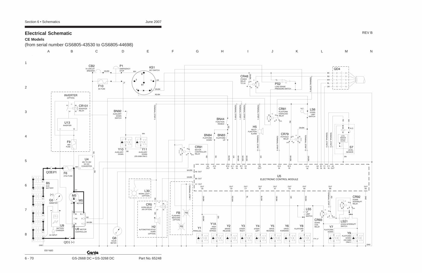
Section 6 • Schematics June 2007
1
2
3
4
5
6
7
8
A B C D E F G H I J K L M N
6 - 70 GS-2668 DC • GS-3268 DC Part No. 65248
Y8PLATFORM
UP
GND
G6HOUR
METER
Y2BRAKE
RELEASE
Y3STEER
RIGHT
Y4STEER
LEFT
Y5DRIVE
REVERSE
Y6DRIVE
FORWARD
Y1PARALLEL
LS6DOWN
LIMIT
SWITCH
A6
OUT
IN
A11
IN IN
BN83PLATFORM
UP
BN44FUNCTION
ENABLE
BN84PLATFORM
DOWN
A12 B12
U5
ELECTRONIC CONTROL MODULE
IN IN IN
A2 B1 C1
C9 C7 B7 A7 C6
OUT OUT OUT OUT OUT
GN
D
B3
OUT
C8
OUT
IN
C12
A1 OUT
FB
FBFBFLASHING
BEACONS
(OPTION)
Y7PLATFORM
DOWN
B6
OUT
Y9PLATFORM
DOWN
(GS-3268
ONLY)
Y1AHIGH
SPEED
BYPASS
RD
WH
BK
BL
OR
H5MULTI-
FUNCTION
ALARM
OUT
B9
IN
A10
IN
C2
IN
A4
IN
B11
IN OUT
C11 A5
RD
WH
BN
N.O.
S7LEVEL
SENSOR
LEVEL
SENSOR
CIRCUIT
BOARD
P1EMERGENCY
STOP
CB27A CIRCUIT
BREAKER
KS1KEY SWITCH
B
B1
31
4 2
B58-6V
BATTERY
GND
(+)
U6 MOTOR
CONTROLLER
B+
3A2
M-
B- 1
U9BATTERY
CHARGER
G5AMMETER
M5MOTORA1
D1
M5
AC INPUT
QD1 -( )
+
-
-
+
+-
-+
++
-
--
-+
+
(+)QD1 +( ) F6275A FUSE
U448V TO 26V
DC-DC
CONVERTER
1
2
3 IN
B10
CR79POTHOLE
RELAY
85
8630
8787A
K3
B8 OUT
A8 OUT
OR
WH
WH
BK
WHGN/BK
WH/BK
RD
RD/BK
GN/BK
RD
BN
85
8630
87
CR48POWER
RELAY
TO U5
K1
GN
/BK
RD
Y11AUXILIARY
DOWN
(GS-3268 ONLY)
Y10AUXILIARY
DOWN
QD4
WH/BK
GN/BK
WH
/BK
OR
OR
WH
/BK
WH
/BK
WH
/BK
BK
/RD
RD
RD
GN
/BK
GN/BK
RD
RD
/BK
OR
OR
/BK
BL/B
K
BL
RD
/WH
GN
/BK
GN
/BK
GN
3
1
2
5
4
3
1
2
5
4
N.C.
CR5HORN RELAY
(H2 OPTION) 8587
86
K2
30
H2AUTOMOTIVE-STYLE
HORN
(OPTION)
RD
GN
L30WORK LIGHT
(OPTION)
F105A FUSE
TE
RM
INA
LS
TR
IP3
TE
RM
INA
LS
TR
IP1
TE
RM
INA
LS
TR
IP2
TE
RM
INA
LS
TR
IP4
TE
RM
INA
LS
TR
IP1
0
TE
RM
INA
LS
TR
IP1
2
TE
RM
INA
LS
TR
IP7
TE
RM
INA
LS
TR
IP1
1
TE
RM
INA
LS
TR
IP9
TE
RM
INA
LS
TR
IP8
85
86 30
87 87A
K4
TE
RM
INA
LS
TR
IP6
CR81PLATFORM
OVERLOAD
RELAY
85
86 30
87 87A
K5
85
86 30
87 87A
K7
TE
RM
INA
LS
TR
IP5
4700 uF
CR93DOWN
COIL
RELAY
LS5UP
LIMIT
SWITCH
PS2LOAD SENSE
PRESSURE SWITCH
85
86 30
87 87A
K6 CR91MOTOR
CONTROLLER
RELAY
OUT
A9
RD
CR92DOWN
INTERRUPT
RELAY
LS21DOWN INTERRUPT
SWITCH
BN92AUXILIARY
DOWN
SWITCH
ES7182D
YL
TE
RM
INA
LS
TR
IP5
INVERTER(OPTION)
8587
86
K4
30
+-
U13INVERTER
CR101INVERTER
RELAY
F980A
FUSE
Electrical SchematicCE Models(from serial number GS6805-43530 to GS6805-44698)
REV B

Section 6 • SchematicsJune 2007
1
2
3
4
5
6
7
8
N M L K J I H G F E D C B A
Part No. 65248 GS-2668 DC • GS-3268 DC 6 - 71
PLATFORM
CONTROLLER
HORN BN5
DRIVE ENABLE BN8
HIGH TORQUE BN6PIN1
PIN2
PIN3
LIFT ENABLE BN9PIN4
POWER LED L19
DRIVE LED L17
LIFT LED L16
POUT4
POUT2
POUT3
FAULT LED L25
POUT5
POUT6
POUT7
POUT9
POUT8
POUT10
HIGH TORQUE LED L21
POUT1
BATTERY LEVEL 1
BATTERY LEVEL 2
BATTERY LEVEL 3
BATTERY LEVEL 4
BATTERY LEVEL 5
G7
PLATFORM CONTROLSMEMBRANE DECAL
H1ALARM
POUT11
PIN11
RD+
-BK
BK
P2EMERGENCY
STOPBK
RD
SW25DIPSWITCH
PIO3
PIO5
PIO4
DATA LINK (LOW)
DATA LINK (HIGH)
GROUND
POWER TO GROUND
POWER TO PLATFORMBK
RD
WH
BL
OR
QD3
D7VOLTAGE
REGULATOR
5V DC
24V DC
PIO2
U3PLATFORM CONTROLS
PRINTED CIRCUIT BOARD
1
2
3
4
5
6
7
8
PIN8
PIN10
PIN9WH/BL
WH/RD
WH
JC1JOYSTICK
CONTROLLER
LE
FT
RIG
HT
SW5FUNCTION ENABLE
A
C
B
D
E
A
C
B
D
E
SW6STEERLEFT/ RIGHT
PP
BL
BN
GY
GN
WH
HALLGENERATOR
Electrical SchematicCE Models
(from serial number GS6805-43530 to GS6805-44698)
REV B
ABBREVIATION LEGEND Item Description B5 Battery Main power
Button BN BN5 = Horn BN6 = High torque BN8 = Drive enable BN9 = Lift enable BN44 = Function enable BN83 = Platform up BN84 = Platform down BN92 = Auxiliary down Circuit breaker CB CB2 = 20 amp (before serial number 41200) CB2 = 7 amp (after serial number 41199) Control relay CR CR5 = Horn CR48 = Power CR79 = Pothole CR81 = Platform overload CR91 = Motor controller CR92 = Down interrupt CR93 = Down delay
D7 Voltage regulator – 24V DC to 5V DC FB1 Flashing beacons (option)
Fuse F F6 = 275A fuse F10 = 5A fuse Gauge G G5 = Ammeter G6 = Hour meter G8 = Diagnostic display
GND Ground Horn or alarm H H1 = Horn H2 = Automotive-style horn H5 = Multifunction alarm
JC1 Joystick controller- drive, steer, platform up/down KS1 Key switch
LED or light L L16 = Lift L17 = Drive L21 = High torque selected L30 = Work light (option)
ABBREVIATION LEGEND Item Description
Limit switch LS LS5 = Platform up LS6 = Platform down LS21 = Down interupt
M5 Hydraulic power unit N.C. Normally closed N.O. Normally open
Power P P1 = Emergency stop button at ground controls P2 = Emergency stop button at platform controls
PS2 Load sense pressure switch Quick disconnect QD QD1 = Battery quick disconnect QD3 = Control cable to ground QD4 = Control cable to platform
S7 Tilt level sensor Switch SW SW5 = Function enable SW6 = Steer left/right Electronic component U U3 = Encoder printed circuit board U4 = Voltage converter U5 = Electronic control module U6 = Motor controller U9 = Battery charger Valve coil Y Y1 = Drive parallel Y1A = Drive parallel (before serial number 41200) Y1A = High speed bypass (after s/n 41199) Y2 = Brake release Y3 = Steer right Y4 = Steer left Y5 = Drive reverse Y6 = Drive forward Y7 = Platform down Y8 = Platform up Y9 = Platform down (GS-3268 only) Y10 = Auxiliary platform down (GS-3268 only) Y11 = Platform down (GS-3268 only)
WIRE COLOR LEGEND Color Description Color Description
BL Blue OR/BK Orange/Black BL/BK Blue/Black PP Purple
BK Black RD Red BK/RD Black/Red RD/BK Red/Black
BN Brown RD/WH Red/White GN Green WH White
GN/BK Green/Black WH/BK White/Black GY Gray YL Yellow OR Orange
June 2007 Section 6 • Schematics
6 - 72
Electrical SchematicCE Models
(from serial number GS6805-43530 to GS6805-44698)
6 - 71

Section 6 • SchematicsJune 2007
6 - 73 6 - 74
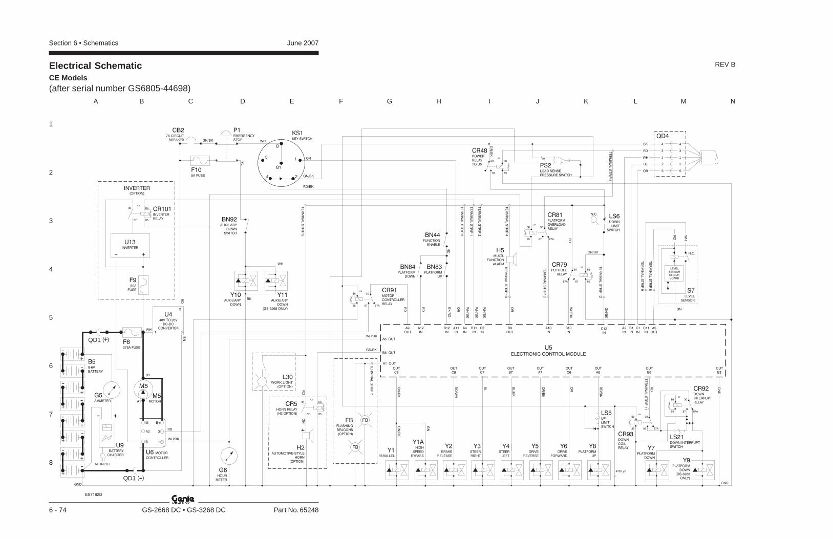
Section 6 • Schematics June 2007
1
2
3
4
5
6
7
8
A B C D E F G H I J K L M N
6 - 74 GS-2668 DC • GS-3268 DC Part No. 65248
Electrical SchematicCE Models(after serial number GS6805-44698)
REV B
Y8PLATFORM
UP
GND
G6HOUR
METER
Y2BRAKE
RELEASE
Y3STEER
RIGHT
Y4STEER
LEFT
Y5DRIVE
REVERSE
Y6DRIVE
FORWARD
Y1PARALLEL
LS6DOWN
LIMIT
SWITCH
A6
OUT
IN
A11
IN IN
BN83PLATFORM
UP
BN44FUNCTION
ENABLE
BN84PLATFORM
DOWN
A12 B12
U5
ELECTRONIC CONTROL MODULE
IN IN IN
A2 B1 C1
C9 C7 B7 A7 C6
OUT OUT OUT OUT OUT
GN
D
B3
OUT
C8
OUT
IN
C12
A1 OUT
FB
FBFB
(OPTION)
FLASHING
BEACONS
Y7PLATFORM
DOWN
B6
OUT
Y9PLATFORM
DOWN
(GS-3268
ONLY)
Y1AHIGH
SPEED
BYPASS
RD
WH
BK
BL
OR
H5MULTI-
FUNCTION
ALARM
OUT
B9
IN
A10
IN
C2
IN
A4
IN
B11
IN OUT
C11 A5
RD
WH
BN
N.O.
S7LEVEL
SENSOR
LEVEL
SENSOR
CIRCUIT
BOARD
P1EMERGENCY
STOP
CB27A CIRCUIT
BREAKER
KS1KEY SWITCH
B
B1
31
4 2
B58-6V
BATTERY
GND
U6 MOTOR
CONTROLLER
B+
3A2
M-
B- 1
G5AMMETER
M5MOTORA1
D1
M5
QD1 -( )
+
-
-
+
+-
-+
++
-
--
-+
+
QD1 +( ) F6275A FUSE
U448V TO 26V
DC-DC
CONVERTER
1
2
3 IN
B10
CR79POTHOLE
RELAY
85
8630
8787A
K3
B8 OUT
A8 OUT
WH
WH
BK
WHGN/BK
WH/BK
RD
GN/BK
RD
BN
85
8630
87
CR48POWER
RELAY
TO U5
K1
GN
/BK
RD
Y11AUXILIARY
DOWN
(GS-3268 ONLY)
Y10AUXILIARY
DOWN
QD4
WH/BK
GN/BK
WH
/BK
OR
OR
WH
/BK
WH
/BK
WH
/BK
BK
/RD
RD
RD
GN
/BK
GN/BK
RD
RD
/BK
OR
OR
/BK
BL/B
K
BL
RD
/WH
GN
/BK
GN
/BK
GN
3
1
2
5
4
3
1
2
5
4
N.C.
CR5HORN RELAY
(H2 OPTION) 8587
86
K2
30
H2AUTOMOTIVE-STYLE
HORN
(OPTION)
RD
GN
F105A FUSE
TE
RM
INA
LS
TR
IP3
TE
RM
INA
LS
TR
IP1
TE
RM
INA
LS
TR
IP2
TE
RM
INA
LS
TR
IP4
TE
RM
INA
LS
TR
IP1
0
TE
RM
INA
LS
TR
IP1
2
TE
RM
INA
LS
TR
IP7
TE
RM
INA
LS
TR
IP1
1
TE
RM
INA
LS
TR
IP9
TE
RM
INA
LS
TR
IP8
85
86 30
87 87A
K4
TE
RM
INA
LS
TR
IP6
CR81PLATFORM
OVERLOAD
RELAY
85
86 30
87 87A
K5
85
86 30
87 87A
K7
TE
RM
INA
LS
TR
IP5
4700 uF
CR93DOWN
COIL
RELAY
LS5UP
LIMIT
SWITCH
PS2LOAD SENSE
PRESSURE SWITCH
85
86 30
87 87A
K6 CR91MOTOR
CONTROLLER
RELAY
OUT
A9
RD
CR92DOWN
INTERRUPT
RELAY
LS21DOWN INTERRUPT
SWITCH
BN92AUXILIARY
DOWN
SWITCH
ES7182D
YL
RD/BK
TE
RM
INA
LS
TR
IP5
OR
U9BATTERY
CHARGER
L30WORK LIGHT
(OPTION)
AC INPUT
INVERTER(OPTION)
8587
86
K4
30
+-
U13INVERTER
CR101INVERTER
RELAY
F980A
FUSE
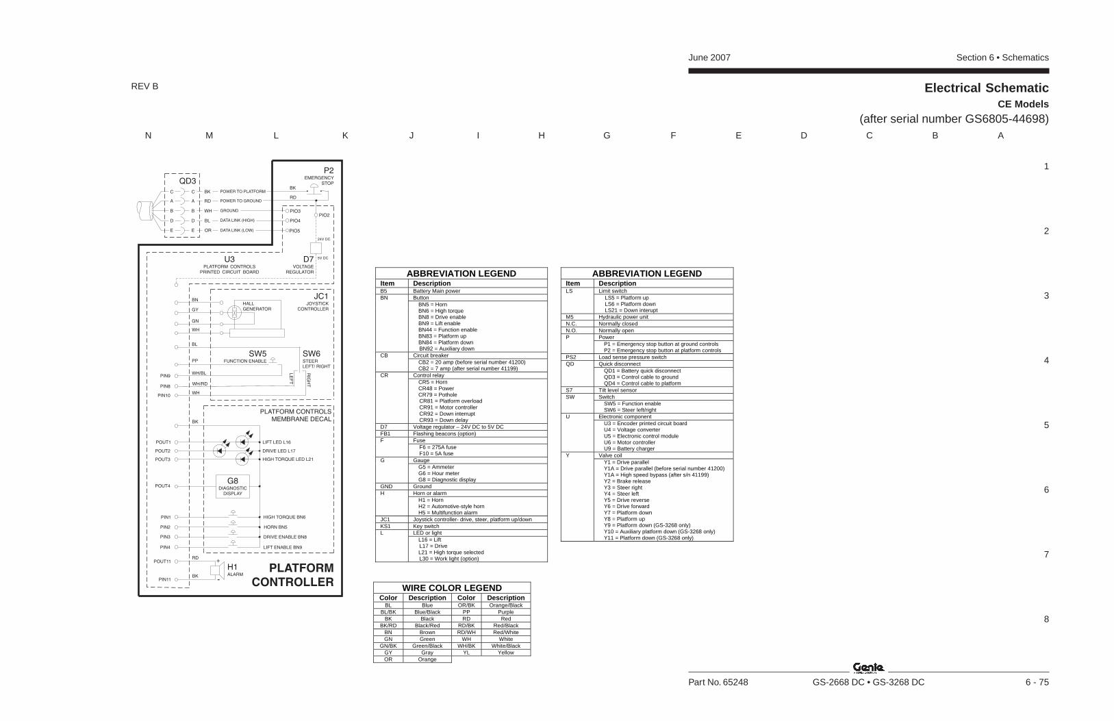
Section 6 • SchematicsJune 2007
1
2
3
4
5
6
7
8
N M L K J I H G F E D C B A
Part No. 65248 GS-2668 DC • GS-3268 DC 6 - 75
Electrical SchematicCE Models
(after serial number GS6805-44698)
REV B
ABBREVIATION LEGEND Item Description B5 Battery Main power
Button BN BN5 = Horn BN6 = High torque BN8 = Drive enable BN9 = Lift enable BN44 = Function enable BN83 = Platform up BN84 = Platform down BN92 = Auxiliary down Circuit breaker CB CB2 = 20 amp (before serial number 41200) CB2 = 7 amp (after serial number 41199) Control relay CR CR5 = Horn CR48 = Power CR79 = Pothole CR81 = Platform overload CR91 = Motor controller CR92 = Down interrupt CR93 = Down delay
D7 Voltage regulator – 24V DC to 5V DC FB1 Flashing beacons (option)
Fuse F F6 = 275A fuse F10 = 5A fuse Gauge G G5 = Ammeter G6 = Hour meter G8 = Diagnostic display
GND Ground Horn or alarm H H1 = Horn H2 = Automotive-style horn H5 = Multifunction alarm
JC1 Joystick controller- drive, steer, platform up/down KS1 Key switch
LED or light L L16 = Lift L17 = Drive L21 = High torque selected L30 = Work light (option)
ABBREVIATION LEGEND Item Description
Limit switch LS LS5 = Platform up LS6 = Platform down LS21 = Down interupt
M5 Hydraulic power unit N.C. Normally closed N.O. Normally open
Power P P1 = Emergency stop button at ground controls P2 = Emergency stop button at platform controls
PS2 Load sense pressure switch Quick disconnect QD QD1 = Battery quick disconnect QD3 = Control cable to ground QD4 = Control cable to platform
S7 Tilt level sensor Switch SW SW5 = Function enable SW6 = Steer left/right Electronic component U U3 = Encoder printed circuit board U4 = Voltage converter U5 = Electronic control module U6 = Motor controller U9 = Battery charger Valve coil Y Y1 = Drive parallel Y1A = Drive parallel (before serial number 41200) Y1A = High speed bypass (after s/n 41199) Y2 = Brake release Y3 = Steer right Y4 = Steer left Y5 = Drive reverse Y6 = Drive forward Y7 = Platform down Y8 = Platform up Y9 = Platform down (GS-3268 only) Y10 = Auxiliary platform down (GS-3268 only) Y11 = Platform down (GS-3268 only)
WIRE COLOR LEGEND Color Description Color Description
BL Blue OR/BK Orange/Black BL/BK Blue/Black PP Purple
BK Black RD Red BK/RD Black/Red RD/BK Red/Black
BN Brown RD/WH Red/White GN Green WH White
GN/BK Green/Black WH/BK White/Black GY Gray YL Yellow OR Orange
G8DIAGNOSTIC
DISPLAY
PLATFORM
CONTROLLER
HORN BN5
DRIVE ENABLE BN8
HIGH TORQUE BN6PIN1
PIN2
PIN3
LIFT ENABLE BN9PIN4
DRIVE LED L17
LIFT LED L16
POUT2
POUT3
POUT4
HIGH TORQUE LED L21
POUT1
PLATFORM CONTROLSMEMBRANE DECAL
H1ALARM
POUT11
PIN11
RD+
-BK
BK
P2EMERGENCY
STOPBK
RD
PIO3
PIO5
PIO4
DATA LINK (LOW)
DATA LINK (HIGH)
GROUND
POWER TO GROUND
POWER TO PLATFORMBK
RD
WH
BL
OR
QD3
D7VOLTAGE
REGULATOR
5V DC
24V DC
PIO2
U3PLATFORM CONTROLS
PRINTED CIRCUIT BOARD
PIN8
PIN10
PIN9WH/BL
WH/RD
WH
JC1JOYSTICK
CONTROLLER
LE
FT
RIG
HT
SW5FUNCTION ENABLE
A
C
B
D
E
A
C
B
D
E
SW6STEERLEFT/ RIGHT
PP
BL
BN
GY
GN
WH
HALLGENERATOR
June 2007 Section 6 • Schematics
6 - 76
Electrical SchematicCE Models
(after serial number GS6805-44698)
6 - 75
Section 6 • SchematicsJune 2007
6 - 77
Hydraulic Symbols Legend andComponent Reference
6 - 78
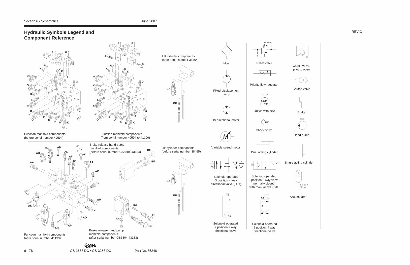
Section 6 • Schematics June 2007
6 - 78 GS-2668 DC • GS-3268 DC Part No. 65248
0.040”
(1 mm)
M
1.03 cu. in.
16.9 cc
Y7
Y8
Y2
AA
ABY2
Y1
Y8
Y5
Y6
Y1A
Y4L
R
R
F
Y3
AC AD
AE
AF
AG
AH
A I
AJ
AK
AL
AM
AN
AO
APAQ
AR
AS
AT
BA
Y6
Y8Y4
Y2
Y1A
Y1B
Y1
Y3
Y5
Y5A
Y6A
A B
D
C
E
FG
H
J
KMNOQ
R
S
T
U
V
W
XY
P
L
I
ZBA
Y6
Y8Y4
Y2
Y1A
Y1B
Y1
Y3
Y5
Y5A
Y6A
A B
DE
F
G
H
J
KMNOQ
T
U
V
W
XY
P
L
I
R
S
BA
BB
BA
BB
BC
BD
BE
BF
BF
BE
Hydraulic Symbols Legend andComponent Reference
Function manifold components(before serial number 40594)
Function manifold components(after serial number 41199)
Filter
Fixed displacementpump
Bi-directional motor
Variable speed motor
Solenoid operated3 position 4 way
directional valve (D01)
Solenoid operated2 position 2 waydirectional valve
Relief valve
Priority flow regulator
Orifice with size
Check valve
Dual acting cylinder
Solenoid operated2 position 2 way valve,
normally closedwith manual over-ride
Solenoid operated2 position 4 waydirectional valve
Check valve,pilot to open
Shuttle valve
Brake
Hand pump
REV C
Function manifold components(from serial number 40594 to 41199)
Brake release hand pumpmanifold components(before serial number GS6804-43184)
Lift cylinder components(after serial number 38464)
Lift cylinder components(before serial number 38465)
Single acting cylinder
Accumulator
Brake release hand pumpmanifold components(after serial number GS6804-43183)
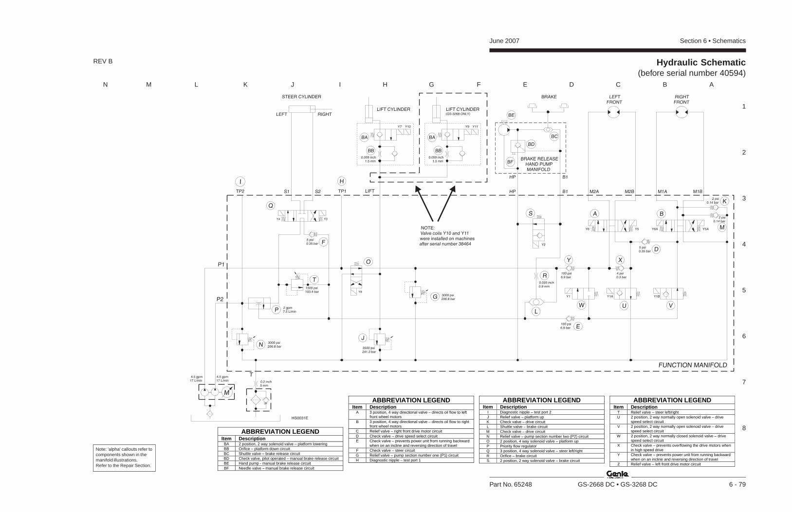
Section 6 • SchematicsJune 2007
1
2
3
4
5
6
7
8
N M L K J I H G F E D C B A
Part No. 65248 GS-2668 DC • GS-3268 DC 6 - 79
ABBREVIATION LEGENDItem Description
T Relief valve – steer left/rightU 2 position, 2 way normally open solenoid valve – drive
speed select circuitV 2 position, 2 way normally open solenoid valve – drive
speed select circuitW 2 position, 2 way normally closed solenoid valve – drive
speed select circuitX Check valve – prevents overflowing the drive motors when
in high speed driveY Check valve – prevents power unit from running backward
when on an incline and reversing direction of travelZ Relief valve – left front drive motor circuit
ABBREVIATION LEGENDItem Description
I Diagnostic nipple – test port 2J Relief valve – platform upK Check valve – drive circuitL Shuttle valve – brake circuitM Check valve – drive circuitN Relief valve – pump section number two (P2) circuitO 2 position, 4 way solenoid valve – platform upP Priority flow regulatorQ 3 position, 4 way solenoid valve – steer left/rightR Orifice – brake circuitS 2 position, 2 way solenoid valve – brake circuit
ABBREVIATION LEGENDItem Description
A 3 position, 4 way directional valve – directs oil flow to leftfront wheel motors
B 3 position, 4 way directional valve – directs oil flow to rightfront wheel motors
C Relief valve – right front drive motor circuitD Check valve – drive speed select circuitE Check valve – prevents power unit from running backward
when on an incline and reversing direction of travelF Check valve – steer circuitG Relief valve – pump section number one (P1) circuitH Diagnostic nipple – test port 1
ABBREVIATION LEGEND Item Description
BA 2 position, 2 way solenoid valve – platform lowering BB Orifice – platform down circuit BC Shuttle valve – brake release circuit BD Check valve, pilot operated – manual brake release circuit BE Hand pump - manual brake release circuit BF Needle valve – manual brake release circuit
1500 psi103.4 bar
3000 psi206.8 bar
4.5 gpm17 L/min
4.5 gpm17 L/min
2 gpm7.5 L/min
P2
P1
T
TP1 M2A M1AM2B M1BS2S1 LIFT
M
RIGHTFRONT
LEFTFRONT
BRAKESTEER CYLINDER
RIGHTLEFT
P
E
O
W U V
D
Q
S
B1HP
HP B1
BD
BC
BE
F
T
H
A BY3Y4
Y2
K
M
TP2
NJ
I
0.059 inch1.5 mm
0.0591.5 mm
inch
LIFT CYLINDER
BA BA
BB BB
Y7 Y9Y10 Y11
LIFT CYLINDER(GS-3268 ONLY)
GY8
3000 psi206.8 bar 3500 psi
241.3 bar
Y1BY1AY1
Y6 Y5 Y6A Y5A
XY
0.2 inch5 mm
NOTE:Valve coils Y10 and Y11were installed on machinesafter serial number 38464
R0.035 inch0.9 mm
L
100 psi6.9 bar
100 psi6.9 bar
4 psi0.3 bar
2 psi0.14 bar
2 psi0.14 bar
5 psi0.35 bar
5 psi0.35 bar
FUNCTION MANIFOLD
BRAKE RELEASEHAND PUMPMANIFOLD
BF
HS0031E
Hydraulic Schematic(before serial number 40594)
REV B
Note: 'alpha' callouts refer tocomponents shown in themanifold illustrations.Refer to the Repair Section.

June 2007 Section 6 • Schematics
6 - 80
Hydraulic Schematic(before serial number 40594)
6 - 79
Section 6 • SchematicsJune 2007
6 - 81
Hydraulic Schematic(from serial number 40594 to 41199)
6 - 82
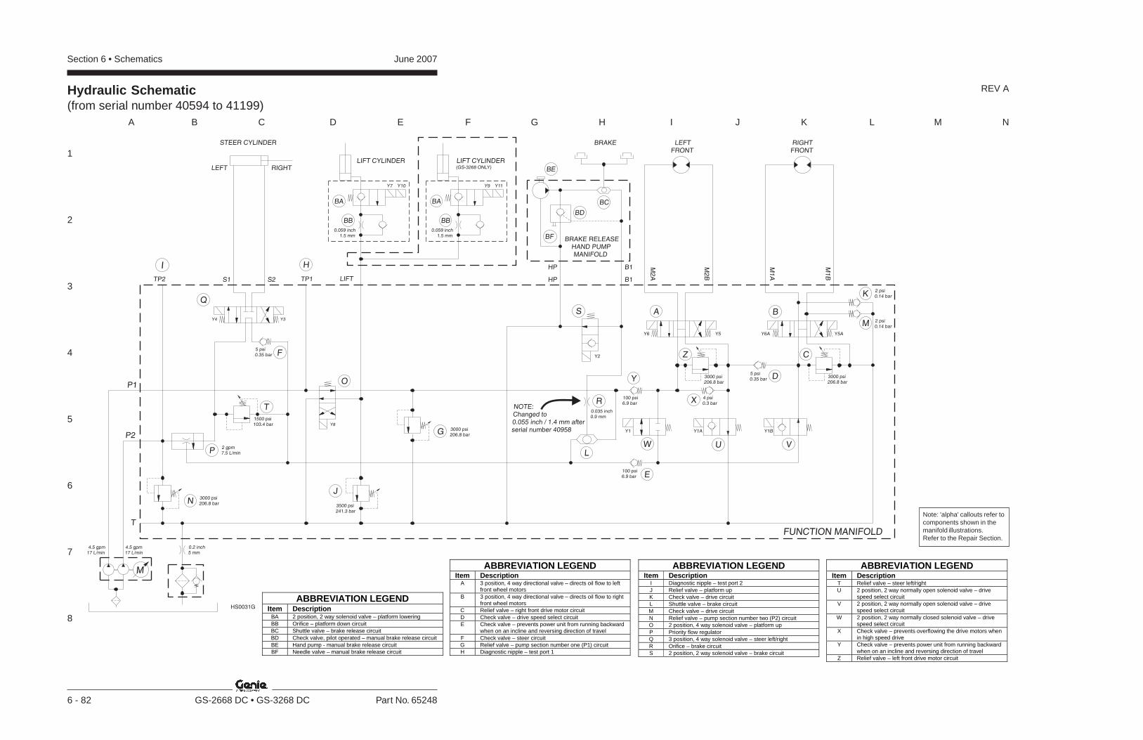
Section 6 • Schematics June 2007
1
2
3
4
5
6
7
8
A B C D E F G H I J K L M N
6 - 82 GS-2668 DC • GS-3268 DC Part No. 65248
ABBREVIATION LEGENDItem Description
T Relief valve – steer left/rightU 2 position, 2 way normally open solenoid valve – drive
speed select circuitV 2 position, 2 way normally open solenoid valve – drive
speed select circuitW 2 position, 2 way normally closed solenoid valve – drive
speed select circuitX Check valve – prevents overflowing the drive motors when
in high speed driveY Check valve – prevents power unit from running backward
when on an incline and reversing direction of travelZ Relief valve – left front drive motor circuit
ABBREVIATION LEGENDItem Description
I Diagnostic nipple – test port 2J Relief valve – platform upK Check valve – drive circuitL Shuttle valve – brake circuitM Check valve – drive circuitN Relief valve – pump section number two (P2) circuitO 2 position, 4 way solenoid valve – platform upP Priority flow regulatorQ 3 position, 4 way solenoid valve – steer left/rightR Orifice – brake circuitS 2 position, 2 way solenoid valve – brake circuit
ABBREVIATION LEGENDItem Description
A 3 position, 4 way directional valve – directs oil flow to leftfront wheel motors
B 3 position, 4 way directional valve – directs oil flow to rightfront wheel motors
C Relief valve – right front drive motor circuitD Check valve – drive speed select circuitE Check valve – prevents power unit from running backward
when on an incline and reversing direction of travelF Check valve – steer circuitG Relief valve – pump section number one (P1) circuitH Diagnostic nipple – test port 1
ABBREVIATION LEGEND Item Description
BA 2 position, 2 way solenoid valve – platform lowering BB Orifice – platform down circuit BC Shuttle valve – brake release circuit BD Check valve, pilot operated – manual brake release circuit BE Hand pump - manual brake release circuit BF Needle valve – manual brake release circuit
Hydraulic Schematic(from serial number 40594 to 41199)
REV A
NOTE:Changed to0.055 inch / 1.4 mm afterserial number 40958
1500 psi103.4 bar
3000 psi206.8 bar
4.5 gpm17 L/min
4.5 gpm17 L/min
2 gpm7.5 L/min
P2
P1
T
TP1S2S1 LIFT
M
BRAKESTEER CYLINDER
RIGHTLEFT
B1
BRAKE RELEASEHAND PUMPMANIFOLD
FUNCTION MANIFOLD
HP
HP B1
Y3Y4
Y2
TP2
Y8
3000 psi206.8 bar 3500 psi
241.3 bar
M2
A
M1
A
RIGHTFRONT
LEFTFRONT
M2
B
M1
B
Y1BY1AY1
3000 psi206.8 bar
3000206.8 bar
psi
Y6 Y5 Y6A Y5A
0.2 inch5 mm
0.035 inch0.9 mm
0.059 inch1.5 mm
0.059 inch1.5 mm
LIFT CYLINDER
BA BA
BB BB
Y7 Y9Y10 Y11
LIFT CYLINDER(GS-3268 ONLY)
BD
BC
BE
W U V
Z C
S A B
R
LP
O
Q
T
H
NJ
I
G
F5 psi0.35 bar
Y
100 psi6.9 bar
E100 psi6.9 bar
X 4 psi0.3 bar
D5 psi0.35 bar
K
M
2 psi0.14 bar
2 psi0.14 bar
BF
HS0031G
Note: 'alpha' callouts refer tocomponents shown in themanifold illustrations.Refer to the Repair Section.
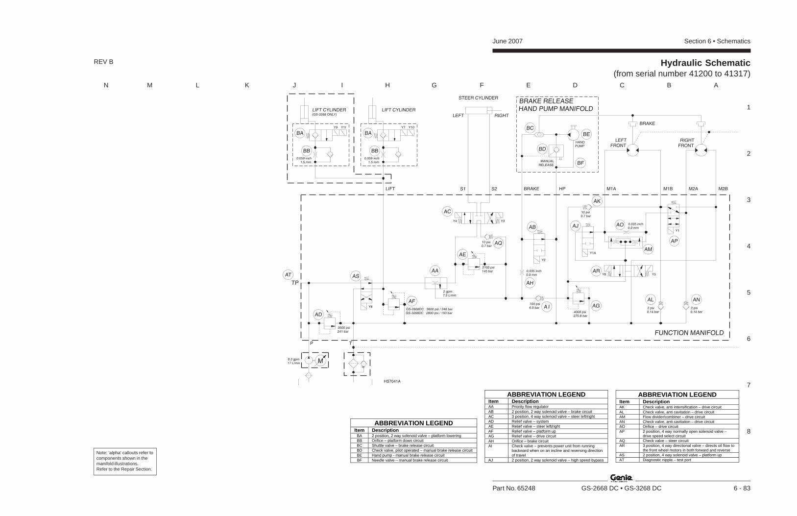
Section 6 • SchematicsJune 2007
1
2
3
4
5
6
7
8
N M L K J I H G F E D C B A
Part No. 65248 GS-2668 DC • GS-3268 DC 6 - 83
REV B Hydraulic Schematic(from serial number 41200 to 41317)
ABBREVIATION LEGEND Item Description AK Check valve, anti intensification – drive circuit AL Check valve, anti cavitation – drive circuit AM Flow divider/combiner – drive circuit AN Check valve, anti cavitation – drive circuit AO Orifice – drive circuit AP 2 position, 4 way normally open solenoid valve –
drive speed select circuit AQ Check valve – steer circuit AR 3 position, 4 way directional valve – directs oil flow to
the front wheel motors in both forward and reverse AS 2 position, 4 way solenoid valve – platform up AT Diagnostic nipple – test port
ABBREVIATION LEGENDItem DescriptionAA Priority flow regulatorAB 2 position, 2 way solenoid valve – brake circuitAC 3 position, 4 way solenoid valve – steer left/rightAD Relief valve – systemAE Relief valve – steer left/rightAF Relief valve – platform upAG Relief valve – drive circuitAH Orifice – brake circuitAI Check valve – prevents power unit from running
backward when on an incline and reversing directionof travel
AJ 2 position, 2 way solenoid valve – high speed bypass
ABBREVIATION LEGEND Item Description
BA 2 position, 2 way solenoid valve – platform lowering BB Orifice – platform down circuit BC Shuttle valve – brake release circuit BD Check valve, pilot operated – manual brake release circuit BE Hand pump - manual brake release circuit BF Needle valve – manual brake release circuit
P
TP
T
8.3 gpm17 L/min M
BRAKE RELEASEHAND PUMP MANIFOLD
HANDPUMP
MANUALRELEASE
HPS1 S2 BRAKE M1A M2AM1B M2B
FUNCTION MANIFOLD
RIGHTFRONT
LEFTFRONT
0.059 inch1.5 mm
LIFT CYLINDER(GS-3268 ONLY)
Y7Y9 Y10Y11
LIFT CYLINDER
0.035 inch0.9 mm
Y8
3500 psi241 bar
2100 psi145 bar
2 gpm7.5 L/min
STEER CYLINDER
RIGHTLEFT
Y3Y4
4000 psi275.8 bar
AL AN
AP
AR
AG
AJAB
AH
A I
AAASAT
AD
AF
AE
AQ
AC
BA BA
BB BB
AK
AO
AM
100 psi6.9 bar 2 psi
0.14 bar2 psi0.14 bar
GS-2668DC 3600 psi / 248 barGS-3268DC 2800 psi / 193 bar
Y1A
LIFT
Y6 Y5
0.035 inch0.9 mm
Y1
BRAKE
Y2
10 psi0.7 bar
10 psi0.7 bar
0.059 inch1.5 mm
BC
BE
BD
BF
HS7041A
Note: 'alpha' callouts refer tocomponents shown in themanifold illustrations.Refer to the Repair Section.

June 2007 Section 6 • Schematics
6 - 84
Hydraulic Schematic(from serial number 41200 to 41317)
6 - 83
Section 6 • SchematicsJune 2007
6 - 85
Hydraulic Schematic(from serial number 41318 to GS6804-43183)
6 - 86
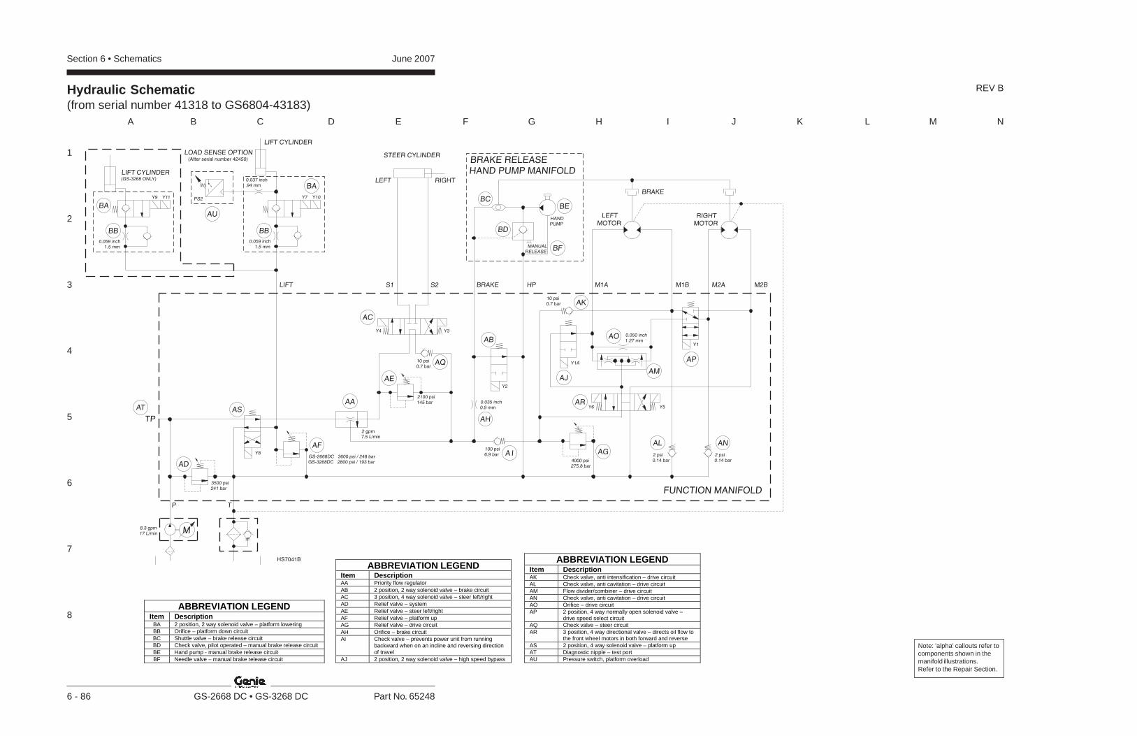
Section 6 • Schematics June 2007
1
2
3
4
5
6
7
8
A B C D E F G H I J K L M N
6 - 86 GS-2668 DC • GS-3268 DC Part No. 65248
Hydraulic Schematic(from serial number 41318 to GS6804-43183)
ABBREVIATION LEGENDItem DescriptionAA Priority flow regulatorAB 2 position, 2 way solenoid valve – brake circuitAC 3 position, 4 way solenoid valve – steer left/rightAD Relief valve – systemAE Relief valve – steer left/rightAF Relief valve – platform upAG Relief valve – drive circuitAH Orifice – brake circuitAI Check valve – prevents power unit from running
backward when on an incline and reversing directionof travel
AJ 2 position, 2 way solenoid valve – high speed bypass
ABBREVIATION LEGEND Item Description
BA 2 position, 2 way solenoid valve – platform lowering BB Orifice – platform down circuit BC Shuttle valve – brake release circuit BD Check valve, pilot operated – manual brake release circuit BE Hand pump - manual brake release circuit BF Needle valve – manual brake release circuit
ABBREVIATION LEGEND Item Description AK Check valve, anti intensification – drive circuit AL Check valve, anti cavitation – drive circuit AM Flow divider/combiner – drive circuit AN Check valve, anti cavitation – drive circuit AO Orifice – drive circuit AP 2 position, 4 way normally open solenoid valve –
drive speed select circuit AQ Check valve – steer circuit AR 3 position, 4 way directional valve – directs oil flow to
the front wheel motors in both forward and reverse AS 2 position, 4 way solenoid valve – platform up AT Diagnostic nipple – test port AU Pressure switch, platform overload
P
TP
T
8.3 gpm17 L/min M
BRAKE RELEASEHAND PUMP MANIFOLD
HANDPUMP
MANUALRELEASE
HPS1 S2 BRAKE M1A M2AM1B M2B
FUNCTION MANIFOLD
RIGHTMOTOR
LEFTMOTOR
0.059 inch1.5 mm
LIFT CYLINDER(GS-3268 ONLY)
Y9 Y11
0.035 inch0.9 mm
Y8
3500 psi241 bar
2 gpm7.5 L/min
STEER CYLINDER
RIGHTLEFT
Y3Y4
4000 psi275.8 bar
AL AN
AP
AR
AG
AJ
AB
AH
A I
AAASAT
AD
AF
AE
AQ
AC
BA
BB
BCBE
BD
AK
AO
AM
100 psi6.9 bar 2 psi
0.14 bar2 psi0.14 bar
GS-2668DC 3600 psi / 248 barGS-3268DC 2800 psi / 193 bar
Y1A
LIFT
Y6 Y5
0.050 inch1.27 mm
Y1
BRAKE
Y2
10 psi0.7 bar
10 psi0.7 bar
Y7 Y10
LIFT CYLINDER
BA
BB
0.059 inch1.5 mm
LOAD SENSE OPTION(After serial number 42450)
0.037 inch.94 mm
BF
PS2
AU
2100 psi145 bar
HS7041B
REV B
Note: 'alpha' callouts refer tocomponents shown in themanifold illustrations.Refer to the Repair Section.
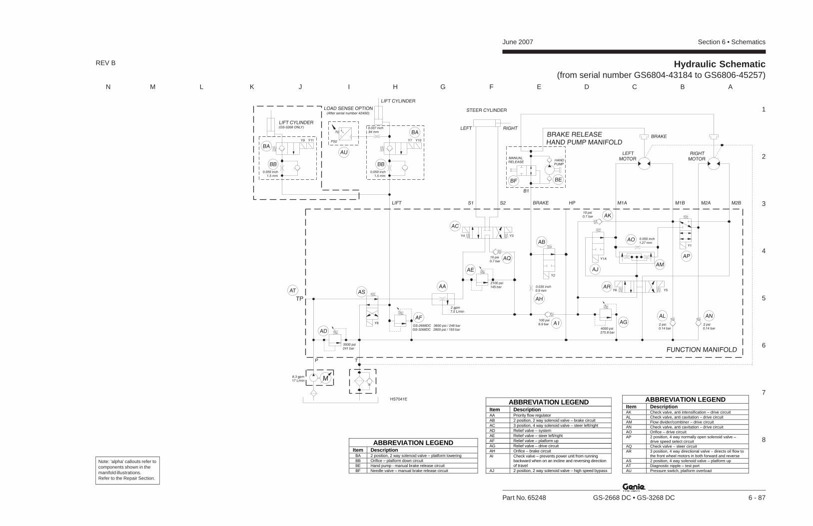
Section 6 • SchematicsJune 2007
1
2
3
4
5
6
7
8
N M L K J I H G F E D C B A
Part No. 65248 GS-2668 DC • GS-3268 DC 6 - 87
REV B Hydraulic Schematic(from serial number GS6804-43184 to GS6806-45257)
ABBREVIATION LEGEND Item Description AA Priority flow regulator AB 2 position, 2 way solenoid valve – brake circuit AC 3 position, 4 way solenoid valve – steer left/right AD Relief valve – system AE Relief valve – steer left/right AF Relief valve – platform up AG Relief valve – drive circuit AH Orifice – brake circuit AI Check valve – prevents power unit from running
backward when on an incline and reversing direction of travel
AJ 2 position, 2 way solenoid valve – high speed bypass
ABBREVIATION LEGEND Item Description
BA 2 position, 2 way solenoid valve – platform lowering BB Orifice – platform down circuit BE Hand pump - manual brake release circuit BF Needle valve – manual brake release circuit
ABBREVIATION LEGEND Item Description AK Check valve, anti intensification – drive circuit AL Check valve, anti cavitation – drive circuit AM Flow divider/combiner – drive circuit AN Check valve, anti cavitation – drive circuit AO Orifice – drive circuit AP 2 position, 4 way normally open solenoid valve –
drive speed select circuit AQ Check valve – steer circuit AR 3 position, 4 way directional valve – directs oil flow to
the front wheel motors in both forward and reverse AS 2 position, 4 way solenoid valve – platform up AT Diagnostic nipple – test port AU Pressure switch, platform overload
P
TP
T
8.3 gpm17 L/min M
BRAKE RELEASEHAND PUMP MANIFOLD
HANDPUMP
MANUALRELEASE
HPS1 S2 BRAKE M1A M2AM1B M2B
FUNCTION MANIFOLD
RIGHTMOTOR
LEFTMOTOR
0.059 inch1.5 mm
LIFT CYLINDER(GS-3268 ONLY)
Y7Y9 Y10Y11
LIFT CYLINDER
0.035 inch0.9 mm
Y8
3500 psi241 bar
2 gpm7.5 L/min
STEER CYLINDER
RIGHTLEFT
Y3Y4
4000 psi275.8 bar
AL AN
AP
AR
AG
AJ
AB
AH
A I
AAASAT
AD
AF
AE
AQ
AC
BA
BA
BB BB
BEBF
AK
AO
AM
100 psi6.9 bar 2 psi
0.14 bar2 psi0.14 bar
GS-2668DC 3600 psi / 248 barGS-3268DC 2800 psi / 193 bar
Y1A
LIFT
Y6 Y5
0.050 inch1.27 mm
Y1
BRAKE
Y2
10 psi0.7 bar
10 psi0.7 bar
0.059 inch1.5 mm
LOAD SENSE OPTION(After serial number 42450)
B1
0.037 inch.94 mm
PS2
AU
2100 psi145 bar
HS7041E
Note: 'alpha' callouts refer tocomponents shown in themanifold illustrations.Refer to the Repair Section.

June 2007 Section 6 • Schematics
6 - 88
Hydraulic Schematic(from serial number GS6804-43184 to GS6806-45257)
6 - 87
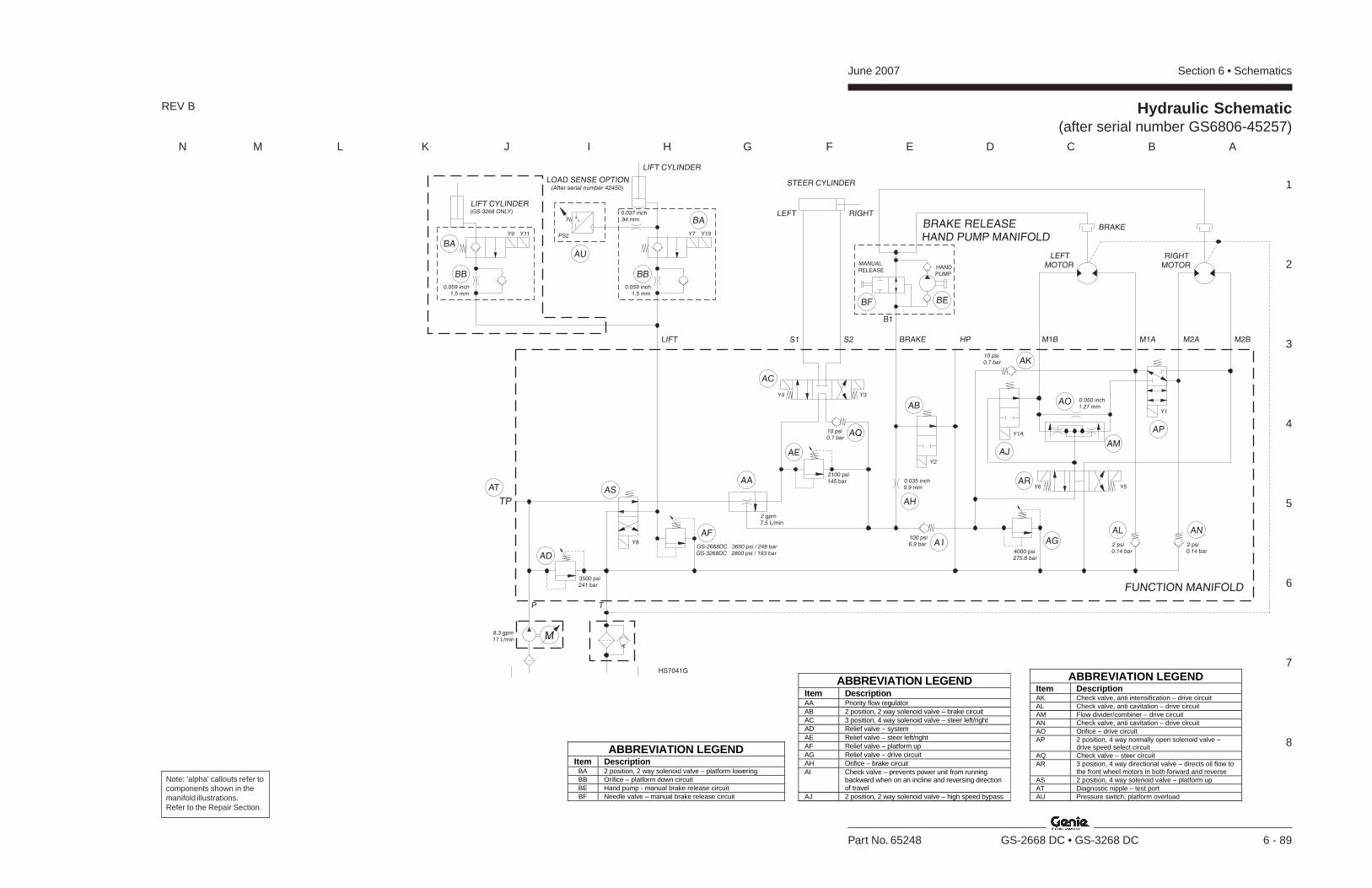
Section 6 • SchematicsJune 2007
1
2
3
4
5
6
7
8
N M L K J I H G F E D C B A
Part No. 65248 GS-2668 DC • GS-3268 DC 6 - 89
Hydraulic Schematic(after serial number GS6806-45257)
ABBREVIATION LEGEND Item Description AA Priority flow regulator AB 2 position, 2 way solenoid valve – brake circuit AC 3 position, 4 way solenoid valve – steer left/right AD Relief valve – system AE Relief valve – steer left/right AF Relief valve – platform up AG Relief valve – drive circuit AH Orifice – brake circuit AI Check valve – prevents power unit from running
backward when on an incline and reversing direction of travel
AJ 2 position, 2 way solenoid valve – high speed bypass
ABBREVIATION LEGEND Item Description
BA 2 position, 2 way solenoid valve – platform lowering BB Orifice – platform down circuit BE Hand pump - manual brake release circuit BF Needle valve – manual brake release circuit
ABBREVIATION LEGEND Item Description AK Check valve, anti intensification – drive circuit AL Check valve, anti cavitation – drive circuit AM Flow divider/combiner – drive circuit AN Check valve, anti cavitation – drive circuit AO Orifice – drive circuit AP 2 position, 4 way normally open solenoid valve –
drive speed select circuit AQ Check valve – steer circuit AR 3 position, 4 way directional valve – directs oil flow to
the front wheel motors in both forward and reverse AS 2 position, 4 way solenoid valve – platform up AT Diagnostic nipple – test port AU Pressure switch, platform overload
P
TP
T
8.3 gpm17 L/min M
BRAKE RELEASEHAND PUMP MANIFOLD
HANDPUMP
MANUALRELEASE
HPS1 S2 BRAKE M1B M2AM1A M2B
FUNCTION MANIFOLD
RIGHTMOTOR
LEFTMOTOR
0.059 inch1.5 mm
LIFT CYLINDER(GS-3268 ONLY)
Y7Y9 Y10Y11
LIFT CYLINDER
0.035 inch0.9 mm
Y8
3500 psi241 bar
2 gpm7.5 L/min
STEER CYLINDER
RIGHTLEFT
Y3Y4
4000 psi275.8 bar
AL AN
AP
AR
AG
AJ
AB
AH
A I
AAASAT
AD
AF
AE
AQ
AC
BA
BA
BB BB
BEBF
AK
AO
AM
100 psi6.9 bar 2 psi
0.14 bar2 psi0.14 bar
GS-2668DC 3600 psi / 248 barGS-3268DC 2800 psi / 193 bar
Y1A
LIFT
Y6 Y5
0.050 inch1.27 mm
Y1
BRAKE
Y2
10 psi0.7 bar
10 psi0.7 bar
0.059 inch1.5 mm
LOAD SENSE OPTION(After serial number 42450)
B1
0.037 inch.94 mm
PS2
AU
2100 psi145 bar
HS7041G
REV B
Note: 'alpha' callouts refer tocomponents shown in themanifold illustrations.Refer to the Repair Section.
June 2007 Section 6 • Schematics
6 - 90
Hydraulic Schematic(after serial number GS6806-45257)
6 - 89
Dis
trib
ute
d B
y:
Genie North America
Genie Australia Pty Ltd.
Genie China
Genie Malaysia
Genie Japan
Genie Korea
Genie Brasil
Genie Holland
Phone 425.881.1800
Toll Free USA and Canada
800.536.1800
Fax 425.883.3475
Phone +61 7 3375 1660
Fax +61 7 3375 1002
Phone +86 21 53852570
Fax +86 21 53852569
Phone +65 98 480 775
Fax +65 67 533 544
Phone +81 3 3453 6082
Fax +81 3 3453 6083
Phone +82 25 587 267
Fax +82 25 583 910
Phone +55 11 41 665 755
Fax +55 11 41 665 754
Phone +31 183 581 102
Fax +31 183 581 566
Genie Scandinavia
Genie France
Genie Iberica
Genie Germany
Genie U.K.
Genie Mexico City
Phone +46 31 575100
Fax +
Phone +33 (0)2 37 26 09 99
Fax +33 (0)2 37 26 09 98
Phone +34 93 579 5042
Fax +34 93 579 5059
Phone 0800 180 9017
Fax +49 422 149 1820
Phone +44 (0)1476 584333
Fax +44 (0)1476 584334
Phone +52 55 5666 5242
Fax +52 55 5666 3241
46 31 579020
Phone +49 422 149 1818
Service M
anu
alG
S-2
66
8 DC
•G
S-3
26
8 DC
(from
intro
du
ctio
n)
Part No.65248
Rev D