paper subjective evaluation of reproduction method for
TRANSCRIPT

Paper
Subjective Evaluation of Reproduction Method for
Frontal Channels of 22.2 Multichannel Sound over a
Direct-View Display
Takehiro Sugimoto (member)†, Satoshi Oode (member)†, Yasushige Nakayama (member)†,Hiroyuki Okubo (member)††
Abstract
A reproduction method for the 11 frontal channels of a 22.2 multichannel sound system (22.2 ch) over a direct-view display
is investigated. NHK is planning to broadcast 8K Super Hi-Vision with 22.2 ch in a pilot broadcasting in 2016. A loudspeaker
array frame has been developed for integration into the direct-view display as a home reproduction system and is used as
a reproduction device of 22.2 ch. Localization of the frontal channels reproduced by the real loudspeakers is subjectively
evaluated in terms of localization accuracy by estimating the difference from the intended localization for an 85-inch display.
Three reproduction methods to synthesize the channels on the display are proposed and evaluated by comparison with a real
loudspeaker placed at an exact channel position. Appropriate reproduction methods for the 11 frontal channels of 22.2 ch
were decided from the results of a subjective evaluation.
Key words: Localization, Sound image, 22.2 multichannel sound system, 8K Super Hi-Vision, Direct-view display.
1. Introduction
NHK is currently developing 8K Super Hi-Vision
(SHV) as a next-generation television system that will
convey a far stronger sense of reality [1]. 8K SHV au-
dio is presented with a 22.2 multichannel sound system
(22.2 ch) composed of 24 channels three-dimensionally
distributed in three layers [2–4]. 8K SHV satellite
broadcasting is scheduled to be launched in 2020. For
the popularization of 8K SHV broadcasting, the quality
of the reproduction device, i.e., the display and loud-
speaker system, is a key factor. A world’s first direct-
view display for 8K SHV was developed with liquid
crystal display (LCD) technology in 85 inch [5]. The
size was selected so that the display can be readily
brought into the home. Concerning 22.2 ch, it funda-
mentally uses separately placed discrete loudspeakers.
However, it is sometimes difficult to install multichannel
audio at home. As a matter of fact, even discrete 5.1 ch
has hardly been accepted in the current market. Hence,
we have been developing a home reproduction method
using a loudspeaker array frame (LAF) integrated into
Received Month xx, 20xx; Revised Month xx, 20xx; Final received
Month xx, 20xx; Accepted Month xx, 20xx
† Science & Technology Research Laboratories, NHK
(1-10-11, Kinuta, Setagaya-ku, Tokyo, 1578510 Japan)
††NHK Engineering System, Inc.
(1-10-11, Kinuta, Setagaya-ku, Tokyo, 1578540 Japan)
a direct-view display [6–9].
The reproduction methods of 22.2 ch with an LAF
can be roughly classified into two groups: those for
the 11 frontal channels around and on the display, and
those for the 11 side and rear channels. The side and
rear channels are auditorily imitated by binaural repro-
duction over loudspeakers [10]. A major issue of the
reproduction methods for the 11 frontal channels is the
three channels placed on the display, because a conven-
tional loudspeaker cannot be equipped on the surface
of a direct-view display.
Several studies on the presentation of a sound image
on a display have been previously reported. Ozawa and
Furuya investigated the localization accuracy of a syn-
thesized sound image using four loudspeakers placed on
each corner of a display [11]. Their result showed that
the central part of the display, which is far from each
loudspeaker, cannot easily synthesize a stable sound im-
age. Furuya et al. also studied the synthesis of a sound
image using four loudspeakers placed at the vertices of a
square [12]. The sound image localization was reported
to be unstable in the case that the intended position
was distant from each loudspeaker, particularly at the
central part of the loudspeaker arrangement. Kimura
and Ando studied the localization of a sound image on
a large screen by using a vertical panning method be-
67
ITE Trans. on MTA Vol. 3, No. 1, pp. 67-75 (2015) Copyright © 2015 by ITE Transactions on Media Technology and Applications (MTA)
Received August 8, 2014; Revised September 24, 2014; AcceptedOctober 21, 2014
tween two loudspeaker arrays set on the top and bottom
edges of the large display [13]. Although their result
showed that a sound image synthesized by vertical pan-
ning did not localize at an intended position without a
video, the studied display size (200 inch) and geomet-
rical configuration (5.2 m distance) were too large for
use at home.
The purpose of this paper is to establish an appro-
priate reproduction method for the 11 frontal channels
of 22.2 ch over the display. Localization of the frontal
channels reproduced by the real loudspeakers was sub-
jectively evaluated in terms of localization accuracy by
estimating the difference from the intended localization
for an 85-inch display. Three reproduction methods to
synthesize the channels on the display were proposed
and evaluated by comparison with a real loudspeaker
placed at an exact channel position.
The rest of this paper is organized as follows. Section
2 outlines 22.2 ch. The loudspeaker arrangement of the
channels around the display is provided in Section 3.
The three reproduction methods for the three channels
on the display are proposed in Section 4. Methodol-
ogy of the subjective evaluation is described in detail
in Section 5. Sections 6 and 7 present our experimental
study, and Section 8 provides a discussion of the results.
Finally, a brief summary of our main findings is given
in Section 9.
2. 22.2 multichannel sound system
The essential concept of 22.2 ch is to provide a highly
immersive sense of presence and reality with a compat-
ibility to existing multichannel audio [2].
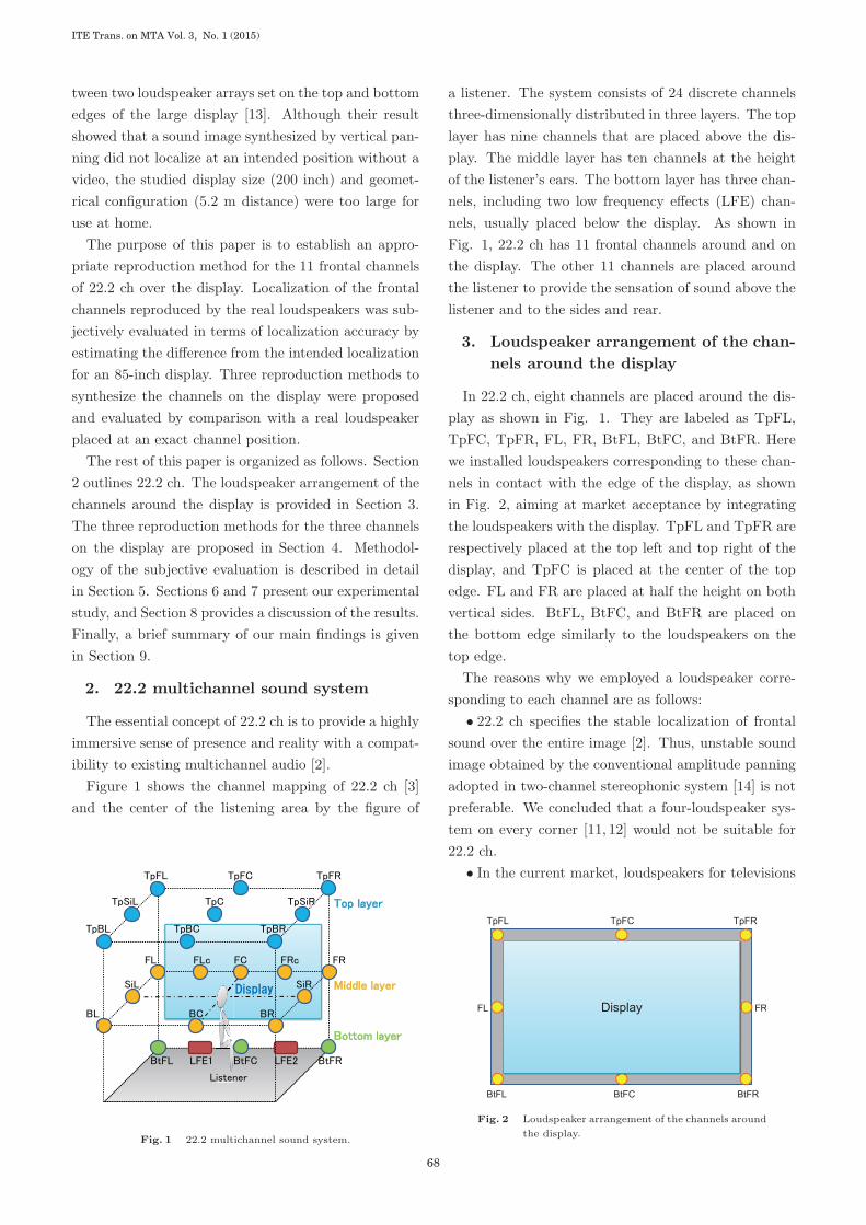
Figure 1 shows the channel mapping of 22.2 ch [3]
and the center of the listening area by the figure of
Fig. 1 22.2 multichannel sound system.
a listener. The system consists of 24 discrete channels
three-dimensionally distributed in three layers. The top
layer has nine channels that are placed above the dis-
play. The middle layer has ten channels at the height
of the listener’s ears. The bottom layer has three chan-
nels, including two low frequency effects (LFE) chan-
nels, usually placed below the display. As shown in
Fig. 1, 22.2 ch has 11 frontal channels around and on
the display. The other 11 channels are placed around
the listener to provide the sensation of sound above the
listener and to the sides and rear.
3. Loudspeaker arrangement of the chan-
nels around the display
In 22.2 ch, eight channels are placed around the dis-
play as shown in Fig. 1. They are labeled as TpFL,
TpFC, TpFR, FL, FR, BtFL, BtFC, and BtFR. Here
we installed loudspeakers corresponding to these chan-
nels in contact with the edge of the display, as shown
in Fig. 2, aiming at market acceptance by integrating
the loudspeakers with the display. TpFL and TpFR are
respectively placed at the top left and top right of the
display, and TpFC is placed at the center of the top
edge. FL and FR are placed at half the height on both
vertical sides. BtFL, BtFC, and BtFR are placed on
the bottom edge similarly to the loudspeakers on the
top edge.
The reasons why we employed a loudspeaker corre-
sponding to each channel are as follows:
• 22.2 ch specifies the stable localization of frontal
sound over the entire image [2]. Thus, unstable sound
image obtained by the conventional amplitude panning
adopted in two-channel stereophonic system [14] is not
preferable. We concluded that a four-loudspeaker sys-
tem on every corner [11, 12] would not be suitable for
22.2 ch.
• In the current market, loudspeakers for televisions
Fig. 2 Loudspeaker arrangement of the channels around
the display.
ITE Trans. on MTA Vol. 3, No. 1 (2015)
68

are required to be as small as possible. However, a
small loudspeaker is apt to suffer from a lack of sound
pressure. To ensure sufficient sound pressure, a loud-
speaker corresponding to each channel is desirable from
the viewpoint of obtaining a sufficient peak margin.
4. Reproduction methods for the chan-
nels on the display
We studied three reproduction methods for the three
channels on the display, i.e., FLc, FC, and FRc. Figure
3 illustrates the three proposed methods.
(i) Amplitude panning by a horizontal pair of
loudspeakers (horizontal pair).
(ii) Amplitude panning by a vertical pair of loud-
speakers (vertical pair).
(iii) Quasi-wavefront synthesis (QWS) by the LAF.
Details of each method are given in the following sec-
tions.
4. 1 Horizontal pair
The horizontal pair is operated by conventional left-
right amplitude panning based on the tangent law
adopted in two-channel stereophonic system [15]. The
tangent law is formulated as follows:
tanφ
tanφ0=
gl − grgl + gr
, (1)
where φ0 is the azimuthal angle of each loudspeaker
from the listener’s front, φ is the offset azimuthal an-
gle of the sound image from the listener’s front, gl and
gr are the gain factors distributing the signal levels to
left and right loudspeaker. The horizontal pair uses the
Fig. 3 Three reproduction methods investigated in this
study: (i) horizontal pair (red), (ii) vertical pair
(green), and (iii) QWS by the LAF (blue).
same loudspeaker units as FL and FR in Fig. 2.
4. 2 Vertical pair
Three pairs of loudspeaker units for FLc, FC, and
FRc are placed on the top and bottom edges as indi-
cated in Fig. 3. The vertical pair is also operated by
the amplitude panning based on the tangent law for-
mulated as follows:
tanϕ
tanϕ0=
gt − gbgt + gb
, (2)
where ϕ0 is the elevation angle of each loudspeaker from
the listener’s front, ϕ is the offset elevation angle of the
sound image from the listener’s front, gt and gb are the
gain factors distributing the signal levels to top and
bottom loudspeaker. Because FLc, FC, and FRc are
positioned at the middle of the vertical pair, gt = gb is
adopted in every case
4. 3 QWS by LAF
We have proposed QWS by the LAF as a reproduc-
tion method for the frontal channels of 22.2 ch [6, 7].
The concept is to modify the Rayleigh integral, which
is an extension of the Kirchhoff-Helmholtz integral over
a boundary plane surface [16, 17], in order to apply to
the LAF.
Figure 4 is a schematic view of QWS by the LAF. r0 is
the listening position, rs is the position of an imaginary
sound source, and rl denotes the position of each loud-
speaker unit. The operation principle of QWS by the
LAF is based on the Rayleigh I integral, which drives a
monopole sound source using a sound pressure gradient
at the position of each monopole sound source [16]. By
modifying the Rayleigh I integral, we define the oper-
ation principle of QWS by the LAF as follows using a
line integral:
Fig. 4 Schematic view of QWS by the LAF based on
the Rayleigh I integral.
69
Paper » Subjective Evaluation of Reproduction Method for Frontal Channels of 22.2 Multichannel Sound over a Direct-View Display

p(r0) ≡ − 1
2π
∮C
∂
∂zp(rl) · e
−ik|r0−rl|
|r0 − rl| ds, (3)
where p is the sound pressure, k is the wave number,
C is the integral path along the LAF, z is the vertical
direction of the display surface, and ds is a line element.
In Eq. (3),∂
∂zp(rl) corresponds to the sound pressure
gradient at each loudspeaker unit rl ande−ik|r0−rl|
|r0 − rl| cor-
responds to the sound wave at the listening position r0.
Moreover, we assume k|rl − rs| � 1 under the geomet-
rical condition that the imaginary sound source is close
to the display for simplification.
By discretizing Eq. (3) using a discrete loudspeaker
unit position indicated with a subscript n and convert-
ing the integral to a summation, we obtain the sound
pressure at the listening position as
p(r0) � Kps2π
m∑n=1
(cos θn
|rln − rs|2 e−ik|rln−rs|
× e−ik|r0−rln |
|r0 − rln |), (4)
where K is a constant of proportionality used to adjust
the sound pressure at the listening position andm is the
number of loudspeaker units. In Eq. 4, the deformation
∂
∂zp(rln) =
cos θn|rln − rs|2 ps · e
−ik|rln−rs| (5)
is adopted, where ps is the sound pressure of the imagi-
nary sound source and θn is the angle between the direc-
tion from the imaginary sound source to the listening
position and the direction from the imaginary sound
source to each loudspeaker unit.
We obtain a concrete operation procedure for the
QWS by the LAF from Eq. (4) as to apply the sig-
nal of an imaginary sound source with gaincos θn
|rln − rs|2and delay
|rln − rs|c
to each loudspeaker unit, where c
is the sound velocity.
The Rayleigh integral is in principle valid in the case
that the boundary plane is an infinite and an infi-
nite number of loudspeakers are uniformly distributed.
Then, we measured the wavefront of QWS by the LAF
with a microphone array to evaluate the synthesized
wavefront [7]. Although a moire due to interference
among the superimposed sound waves from each loud-
speaker unit was observed in the measured wavefront, a
secondary wavefront was approximately synthesized as
an envelope of superimposed primary sound waves. In
this paper, the localization synthesized by QWS by the
LAF will be subjectively evaluated.
5. Methodology of subjective evaluation
5. 1 Procedure and stimuli
Listeners were required to plot the center of a per-
ceived sound image on an answer sheet on which the
loudspeaker units and guide grids were printed. We
used a full-band white noise with a duration of 1 s as a
stimulus. The stimulus was repeated three times with
1 s intervals and 5 s was given to listeners to answer.
Thus, each trial had a duration of 10 s. The listeners
evaluated two different trial sequences which were ran-
domized in each sequence to counterbalance the effect
of the trial order. All stimuli were presented at a sound
pressure level of 70 dB (A-weighted).
5. 2 Evaluation room and equipment
We carried out the subjective evaluation in an acous-
tic evaluation room at NHK. The design of the room
strictly adheres to Rec. ITU-R BS.1116-1 [18]. The
reverberation time is 0.38 s at 500 Hz, the room dimen-
sions are 6.4 m (W) × 8.0 m (D) × 4.5 m (H), and the
room complies with NR-10.
Figure 5 shows the LAF for the 85-inch LCD. The
size of the LAF is 2.3 m (W) × 1.4 m (H) × 0.08 m
(D). It uses 16 units with 70 mm diameter and 86 loud-
speaker units with 35 mm diameter. The large units
were placed at intervals of 540 mm in the horizontal ar-
ray as indicated by the red dashed circles in Fig. 5. At
half height of each vertical array, a large unit was also
placed. These large units were used in horizontal and
vertical pairs. The small units were arranged with in-
tervals of 60 mm. The QWS used 102 loudspeaker units
in total. As a real sound source of FLc, FC, and FRc,
we fabricated a loudspeaker with a large loudspeaker
unit as indicated by the blue dashed circles.
We did not use a curtain to conceal the loudspeaker
unit because even perforated curtain was found to in-
Fig. 5 LAF for 85-inch LCD display.
ITE Trans. on MTA Vol. 3, No. 1 (2015)
70

duce diffraction at its edge affecting the localization of
a sound image in a preliminary experiment. To reduce
the ventriloquism effect [19], which usually enhances
localization on visible object, we added several dummy
loudspeakers both inside and outside of the LAF.
5. 3 Listeners
A total of 18 listeners participated in the evaluation,
three females and 15 males in their 20s to 50s. They
were engaged in audio or speech processing research ex-
cept for one student who was studying audio signal pro-
cessing. The listeners performed the evaluation alone.
The height of the ears was adjusted to the center of the
LAF. The listeners were asked not to move their heads
during the evaluation, but their heads were not fixed to
the chair.
6. Subjective evaluation I: Localization of
the frontal channels of 22.2 ch repro-
duced by the real loudspeakers
In this section, we evaluate the localization accuracy
of the frontal channels of 22.2 ch reproduced by the
corresponding real loudspeaker indicated in Fig. 5 to
examine an ideal condition.
Figure 6 shows the perceived localizations evaluated
in front of FC, whose coordinate on the grid is (0, 0),
at a distance of 1.9 m. Each mean value is presented as
a circle with a 95% confidence interval (CI) in both the
horizontal and vertical directions. A pink circle shows
the actual location of a real loudspeaker both in Sec-
tions 6 and 7. The geometrical relation between the
frontal channels and the listener is provided in the po-
lar coordinate system in Appendix. We can estimate
the localization accuracy from the length of the 95% CI
and the closeness to the pink circle.
Figure 7 shows the perceived localizations evaluated
in front of FLc (−2, 0) at a distance of 1.9 m.
It was found from Figs. 6 and 7 that most of the
channels of the middle and bottom layers are upwardly
perceived compared with the height of the reproducing
loudspeaker. In contrast, the channels of the top layer
localize at the position of the loudspeaker. In addition,
the 95% CI in the vertical direction tends to be longer
for the lower channels. Reasonable localization accu-
racy in the horizontal direction is achieved regardless
the listening position.
�� �� �� �� �� � � � � � �
��
��
��
�
�
�
�
�������������������������������������������������������������������������������������
����������������������������������������������������������������������������������
�������������������������������������������������������������������������������
�����������������
������
�� ������������������� ��������
���
Fig. 6 Perceived localizations evaluated in front of FC
at a distance of 1.9 m.
�� �� �� �� �� � � � � � �
��
��
��
�
�
�
�
���
����������������������������������������������������������������������������������
�������������������������������������������������������������������������������������
������������������������������������������������������������������������������������������������
������
�� ������������������� ��������
Fig. 7 Perceived localizations evaluated in front of FLc
at a distance of 1.9 m.
7. Subjective evaluation II: Localization
of the synthesized channels on the dis-
play
In this section, we compare the localization accuracy
of the three reproduction methods proposed in Section
4 with a real loudspeaker placed at each channel. Note
that the localization accuracy is evaluated only for FLc,
FC, and FRc, so that the outside of them is not covered
in this study.
7. 1 Evaluation in front of FC
Figures 8(a)-(c) show perceived localizations evalu-
ated in front of FC (0, 0) at a distance of 1.9 m. A
mean value is presented as a dot with a 95% CI in both
the horizontal and vertical directions. A pink circle
shows the actual location of a real loudspeaker.
In Fig. 8(a), the vertical pair and QWS by the LAF
are found to localize at a similar position to the real
71
Paper » Subjective Evaluation of Reproduction Method for Frontal Channels of 22.2 Multichannel Sound over a Direct-View Display

Fig. 8 Perceived localizations evaluated in front of FC
channel at a distance of 1.9 m. The intended
localizations are (a) FC, (b) FLc, and (c) FRc.
loudspeaker because the 95% CIs overlap each other.
However, the horizontal pair is slightly shifted from the
real loudspeaker.
Figure 8(b) shows that the horizontal and vertical
pairs can localize at FLc as intended. QWS by the
LAF localizes near the left array, which is a different
from the other results. The reason why QWS by the
Fig. 9 Perceived localizations evaluated in front of FLc
channel at a distance of 1.9 m. The intended
localizations are (a) FC, (b) FLc, and (c) FRc.
LAF does not provide an appropriate localization will
be discussed later in Section 8.
Figure 8(c) is a symmetrical configuration to Fig.
8(b) and the result is also symmetrical; thus, this result
can be understood similarly to Fig. 8(b).
7. 2 Evaluation in front of FLc
Figures 9(a)-(c) show perceived localizations evalu-
ITE Trans. on MTA Vol. 3, No. 1 (2015)
72
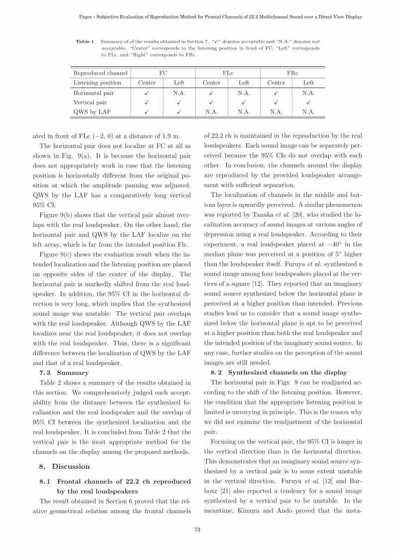
Table 1 Summary of of the results obtained in Section 7. “�” denotes acceptable and “N.A.” denotes not
acceptable. “Center” corresponds to the listening position in front of FC, “Left” corresponds
to FLc, and “Right” corresponds to FRc.
Reproduced channel FC FLc FRc
Listening position Center Left Center Left Center Left
Horizontal pair � N.A. � N.A. � N.A.
Vertical pair � � � � � �QWS by LAF � � N.A. N.A. N.A. N.A.
ated in front of FLc (−2, 0) at a distance of 1.9 m.
The horizontal pair does not localize at FC at all as
shown in Fig. 9(a). It is because the horizontal pair
does not appropriately work in case that the listening
position is horizontally different from the original po-
sition at which the amplitude panning was adjusted.
QWS by the LAF has a comparatively long vertical
95% CI.
Figure 9(b) shows that the vertical pair almost over-
laps with the real loudspeaker. On the other hand, the
horizontal pair and QWS by the LAF localize on the
left array, which is far from the intended position Flc.
Figure 9(c) shows the evaluation result when the in-
tended localization and the listening position are placed
on opposite sides of the center of the display. The
horizontal pair is markedly shifted from the real loud-
speaker. In addition, the 95% CI in the horizontal di-
rection is very long, which implies that the synthesized
sound image was unstable. The vertical pair overlaps
with the real loudspeaker. Although QWS by the LAF
localizes near the real loudspeaker, it does not overlap
with the real loudspeaker. Thus, there is a significant
difference between the localization of QWS by the LAF
and that of a real loudspeaker.
7. 3 Summary
Table 2 shows a summary of the results obtained in
this section. We comprehensively judged each accept-
ability from the distance between the synthesized lo-
calization and the real loudspeaker and the overlap of
95% CI between the synthesized localization and the
real loudspeaker. It is concluded from Table 2 that the
vertical pair is the most appropriate method for the
channels on the display among the proposed methods.
8. Discussion
8. 1 Frontal channels of 22.2 ch reproduced
by the real loudspeakers
The result obtained in Section 6 proved that the rel-
ative geometrical relation among the frontal channels
of 22.2 ch is maintained in the reproduction by the real
loudspeakers. Each sound image can be separately per-
ceived because the 95% CIs do not overlap with each
other. In conclusion, the channels around the display
are reproduced by the provided loudspeaker arrange-
ment with sufficient separation.
The localization of channels in the middle and bot-
tom layer is upwardly perceived. A similar phenomenon
was reported by Tanaka et al. [20], who studied the lo-
calization accuracy of sound images at various angles of
depression using a real loudspeaker. According to their
experiment, a real loudspeaker placed at −40◦ in the
median plane was perceived at a position of 5◦ higher
than the loudspeaker itself. Furuya et al. synthesized a
sound image among four loudspeakers placed at the ver-
tices of a square [12]. They reported that an imaginary
sound source synthesized below the horizontal plane is
perceived at a higher position than intended. Previous
studies lead us to consider that a sound image synthe-
sized below the horizontal plane is apt to be perceived
at a higher position than both the real loudspeaker and
the intended position of the imaginary sound source. In
any case, further studies on the perception of the sound
images are still needed.
8. 2 Synthesized channels on the display
The horizontal pair in Figs. 9 can be readjusted ac-
cording to the shift of the listening position. However,
the condition that the appropriate listening position is
limited is unvarying in principle. This is the reason why
we did not examine the readjustment of the horizontal
pair.
Focusing on the vertical pair, the 95% CI is longer in
the vertical direction than in the horizontal direction.
This demonstrates that an imaginary sound source syn-
thesized by a vertical pair is to some extent unstable
in the vertical direction. Furuya et al. [12] and Bar-
bour [21] also reported a tendency for a sound image
synthesized by a vertical pair to be unstable. In the
meantime, Kimura and Ando proved that the insta-
73
Paper » Subjective Evaluation of Reproduction Method for Frontal Channels of 22.2 Multichannel Sound over a Direct-View Display
bility of a sound image synthesized by a vertical pair
was markedly reduced by presenting the image together
with a video [13]. This is the so-called ventriloquism
effect [19], and thus, we can expect the improved local-
ization of the channels on the display when 22.2 ch is
simultaneously reproduced with 8K SHV video.
Another concern is that the vertical localization is
shifted if the listening position is biased in the vertical
direction. The ventriloquism effect will work provided
the shift in the listening position is small. However,
an appropriate localization will not be obtained if the
listening position shifts to the edge of the display or
outside the display. This issue strongly depends on the
display size and the listening position, implying that a
continuous study is still needed.
8. 3 QWS by LAF
The reason why QWS by the LAF did not provide an
appropriate localization is considered as follows. QWS
by the LAF algorithm aims to distribute the signal level
to each loudspeaker unit in accordance with the inverse
square law. As mentioned in Section 4. 3, the Rayleigh
integral is valid in case that the boundary plane is in-
finite and an infinite number of loudspeakers are uni-
formly distributed. However, the LAF acts similarly
to a combination of one vertical pair and one horizon-
tal pair whose crosspoint corresponds to each imagi-
nary sound source, in which the signal level distribution
should follow the inverse law rather than the inverse
square law. The observed localization error is due to
this inconsistency.
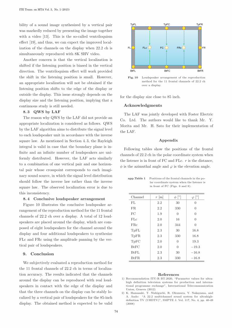
8. 4 Conclusive loudspeaker arrangement
Figure 10 illustrates the conclusive loudspeaker ar-
rangement of the reproduction method for the 11 frontal
channels of 22.2 ch over a display. A total of 12 loud-
speakers are placed around the display, which are com-
posed of eight loudspeakers for the channel around the
display and four additional loudspeakers to synthesize
FLc and FRc using the amplitude panning by the ver-
tical pair of loudspeakers.
9. Conclusion
We subjectively evaluated a reproduction method for
the 11 frontal channels of 22.2 ch in terms of localiza-
tion accuracy. The results indicated that the channels
around the display can be reproduced with real loud-
speakers in contact with the edge of the display and
that the three channels on the display can be stably lo-
calized by a vertical pair of loudspeakers for the 85-inch
display. The obtained method is expected to be valid
Fig. 10 Loudspeaker arrangement of the reproduction
method for the 11 frontal channels of 22.2 ch
over a display.
for the display size close to 85 inch.
Acknowledgments
The LAF was jointly developed with Foster Electric
Co. Ltd. The authors would like to thank Mr. Y.
Morita and Mr. H. Sato for their implementation of
the LAF.
Appendix
Following tables show the positions of the frontal
channels of 22.2 ch in the polar coordinate system when
the listener is in front of FC and FLc. r is the distance,
φ is the azimuthal angle and ϕ is the elevation angle.
app.Table 1 Positions of the frontal channels in the po-
lar coordinate system when the listener is
in front of FC (Figs. 6 and 8).
Channel r [m] φ [◦] ϕ [◦]
FL 2.2 30 0
FR 2.2 330 0
FC 1.9 0 0
FLc 2.0 16 0
FRc 2.0 344 0
TpFL 2.3 30 16.8
TpFR 2.3 330 16.8
TpFC 2.0 0 19.3
BtFC 2.0 0 −19.3BtFL 2.3 30 −16.8BtFR 2.3 330 −16.8
References1) Recommendation ITU-R BT.2020, “Parameter values for ultra-
high definition television systems for production and interna-
tional programme exchange”, International Telecommunication
Union, Geneva (2012)
2) K. Hamasaki, T. Nishiguchi, R. Okumura, Y. Nakayama, and
A. Ando: “A 22.2 multichannel sound system for ultrahigh-
definition TV (UHDTV)”, SMPTE J. Vol. 117, No. 4, pp. 40-49
(2008)
ITE Trans. on MTA Vol. 3, No. 1 (2015)
74

app.Table 2 Positions of the frontal channels in the po-
lar coordinate system when the listener is
in front of FLc (Figs. 7 and 9).
Channel r [m] φ [◦] ϕ [◦]
FL 2.0 16 0
FR 2.5 319 0
FC 2.0 344 0
FLc 1.9 0 0
FRc 2.2 330 0
TpFL 2.1 16 18.6
TpFR 2.6 319 14.7
TpFC 2.1 344 18.6
BtFC 2.1 344 −18.6BtFL 2.1 16 −18.6BtFR 2.6 319 −14.7
3) SMPTE ST 2036-2-2008, “Ultra high definition television - audio
characteristics and audio channel mapping for program produc-
tion” (2008)
4) Recommendation ITU-R BS.2051, “Advanced sound system
for programme production”, International Telecommunication
Union, Geneva (2014)
5) T. Kumakura, M. Shiomi, S. Horino, S. Imai, and S. Mizushima:
“Super Hi-Vision 8Kx4K direct-view LCD for next generation
TV”, Eurodisplay 2011, XXXI International Display Research
Conference, 14.5 (2011)
6) T. Sugimoto, K. Matsui, and H. Okubo: “A loudspeaker array
frame reproducing 22.2 multichannel sound for Super Hi-Vision
flat panel display”, 2012 NAB BEC Proceedings, pp. 16-21 (April
2012)
7) H. Okubo, T. Sugimoto, S. Oishi, and A. Ando: “A method for
reproducing frontal sound field of 22.2 multichannel sound uti-
lizing a loudspeaker array frame”, The 133rd Convention of the
Aud. Eng. Soc., Convention Paper 8714 (October 2012)
8) K. Matsui, S. Oishi, T. Sugimoto, S. Oode, Y. Nakayama, H.
Okubo, A. Ando, H. Sato, K. Mizuno, and Y. Morita: “Repro-
duction of 22.2 multichannel sound with FPD-integrated loud-
speakers for home use”, 20th International Display Workshops
(IDW’13), PDP2-1, pp. 679-682 (December 2013)
9) S. Oode, K. Matsui, S. Oishi, T. Sugimoto, and Y. Nakayama:
“12-loudspeaker system for three-dimensional sound integrated
with a flat-panel display”, SMPTE J. Vol. 123, pp. 35-43 (2014)
10) K. Matsui and A. Ando: “Binaural reproduction of 22.2 multi-
channel sound with loudspeaker array frame”, The 135th Con-
vention of the Aud. Eng. Soc., Convention Paper 8954 (October
2013)
11) K. Ozawa and T. Furuya: “Effects of positioning with synthetic
sound images on exploration of object in GUI”, IPSJ J. Vol. 42,
No. 6, pp. 1299-1310 (2001)
12) T. Furuya, K. Ozawa, and Y. Suzuki: “Two-dimensional localiza-
tion of a phantom sound image controlled by the level differences
among four loudspeakers in a vertical plane facing a listener”,
Acoust. Sci. & Tech. Vol. 25, pp. 493-495 (2004)
13) T. Kimura and H. Ando: “3D audio system using multiple ver-
tical panning for large-screen multiview 3D video display”, ITE
Trans. Med. Tech. Appl. Vol. 2, No. 1, pp. 1-13 (2014)
14) F. Rumsey: “Spatial Audio”, Focal Press, Oxford (2001)
15) V. Pulkki: “Virtual sound source positioning using vector base
amplitude panning,” J. Aud. Eng. Soc. Vol. 45, No. 6, pp. 456-
466 (1997)
16) D. de. Vries: “Wave Field Synthesis”, Audio Engineering Society,
New York (2009)
17) A. Berkhout, D. de Vries, and P. Vogel: “Acoustic control by
wave field synthesis”, J. Acoust. Soc. Am. Vol. 93, pp. 2764-2778
(1993)
18) Recommendation ITU-R BS.1116-1 “Method for subjective as-
sessment of small impairments in audio systems including
multichannel sound systems,” International Telecommunication
Union, Geneva (1994)
19) J. Sato, K. Fukue, Y. Kinoshita, and K. Ozawa: “Evaluation of
the ventriloquism effect in the vertical influenced by audio re-
production systems”, The Journal of The Institute of Image In-
formation and Television Engineers, Vol. 63, No. 1, pp. 110-113
(2009)
20) Y. Tanaka, H. Hokari, and S. Shimada: “Sound localization ac-
curacy versus depression angle in multichannel reproduction sys-
tem”, IEICE Tech. Rep. EA2009-56 (2009)
21) J. Barbour: “Elevation perception: phantom images in the ver-
tical hemi-sphere”, 24th International Conference of Aud. Eng.
Soc. (2003)
Takehiro Sugimoto received his B.E.and M.E. degrees in electronic engineering from theUniversity of Tokyo, Tokyo, Japan, in 1999 and2001, respectively. He also received a Ph.D. in in-formation processing from Tokyo Institute of Tech-nology, Tokyo, Japan, in 2013. He joined NHK in2001 and has been working at Science & TechnologyResearch Laboratories since 2004. His research in-terests are acoustic transducers, audio coding, andthree-dimensional audio reproduction. He is cur-rently engaged in MPEG and ARIB standardiza-tion.
Satoshi Oode received his B.S. degree inphysics from Sophia University and his M.S. de-gree in computational intelligence and systems sci-ence from Tokyo Institute of Technology, Tokyo,Japan, in 1997 and 1999, respectively. He joinedNHK in 1999 and worked as a video engineer inthe Programs Engineering Center. Since 2001 hehas been working at Science & Technology ResearchLaboratories. His research interests include emo-tion evoked by music, psychoacoustics, and three-dimensional acoustic space perception.
Yasushige Nakayama received his B.E.and M.E. degrees from the University of Iwate,Iwate, Japan, in 1992 and 1994, respectively. Hejoined NHK in 1994. He has mainly been en-gaged in the research and development of a three-dimensional sound system for television. He is cur-rently a senior research engineer of NHK Science &Technology Research Laboratories.
Hiroyuki Okubo received his M.E. degreefrom Meiji University, Tokyo, Japan, and joinedNHK in 1992. He has been on loan to NHK Engi-neering System, Inc. since 2014 and is currently achief engineer. He has been engaged in the researchand development of a 22.2 multichannel sound sys-tem for Super Hi-Vision.
75
Paper » Subjective Evaluation of Reproduction Method for Frontal Channels of 22.2 Multichannel Sound over a Direct-View Display