paper open access (iihfwvrivrlo …
TRANSCRIPT
IOP Conference Series: Earth and Environmental Science
PAPER • OPEN ACCESS
Effects of soil-structure interaction on base-isolated structuresTo cite this article: M. A. Aden et al 2019 IOP Conf. Ser.: Earth Environ. Sci. 357 012031
View the article online for updates and enhancements.
You may also likeBio-inspired passive base isolator withtuned mass damper inerter for structuralcontrolHaitao Li, Henry T Yang, Isaac Y Kwon etal.
-
Short Review on Soil-StructureImplementation in Base IsolatedStructuresKristiana Bezha and Arcan Yanik
-
Development and characterization of amagnetorheological elastomer basedadaptive seismic isolatorYancheng Li, Jianchun Li, Weihua Li et al.
-
This content was downloaded from IP address 65.21.228.167 on 25/10/2021 at 14:57
Content from this work may be used under the terms of the Creative Commons Attribution 3.0 licence. Any further distributionof this work must maintain attribution to the author(s) and the title of the work, journal citation and DOI.
Published under licence by IOP Publishing Ltd
Sustainable Civil and Construction Engineering Conference
IOP Conf. Series: Earth and Environmental Science 357 (2019) 012031
IOP Publishing
doi:10.1088/1755-1315/357/1/012031
1
Effects of soil-structure interaction on base-isolated structures
M. A. Aden1, Alyaa.A.Al-Attar
2,F.Hejazi
3,*,M. Dalili
1and Nima Ostovar
1
1Department of Civil Engineering, Faculty of Engineering, Universiti Putra Malaysia,
43400 UPM, Serdang, Selangor, Malaysia 2Department of Civil Engineering, Northern Technical University, Iraq
3housing Research Centre, Faculty of Engineering, Universiti Putra Malaysia, 43400
UPM, Serdang, Selangor, Malaysia
Abstract. Structural integrity and seismic protection of the buildings against earthquake have
been challenging among structural engineers. Many studies have been devoted to development
of seismic isolators to improve the seismic behavior of civil structures. This study presents the
analysis of building structures with SAP2000 considering soil structure interaction and base
isolation effects under El Centro. Four different models are analyzed including fixed base
structure, base isolated structure, frame supported by spring representing the soil and structure
with combined base isolation and spring. The seismic results are investigated in terms of
displacement, shear force, axial force, moment and drift of the columns and beams. It was
observed that the soil structure interaction provides some flexibility to the structure by
increasing the displacements of the structure and imposing internal forces variation to the
system. Therefore, modeling base isolation together with consideration of soil structure
interaction leads to better prediction of structural response.
1. Introduction Geological faults cause earthquake rupture and as a consequence of that earthquakes have claimed
hundreds of thousands of life in the past years and technology improvements have slightly decreased
the death tolls. Property damage, loss of lives and many more casualties caused by an earthquake must
be lowered and to do so engineers should come up with solutions [1- 3]. Inclusion of soil-structure
interaction (SSI) in seismic analysis has proved to enhance the seismic performance of civil structures.
Soil structure interaction had not been seriously given enough attention to evaluate until the 1971.
Significant number of journal papers like and design guides were published in 1970s and showed
importance of soil SSI [4, 5]. SSI was investigated in 1980s and 1990s through numerical methods [6-
9]. Furthermore, effects of such interaction analysis on special structures have been studied by many
researchers including [10, 11]. Twomethods were presentedfornsoil structure interaction analysis
during the seismic motion[12]. As the first method, the change of motions in the structure and
surrounding soils was considered and in the second one the motion of surrounding soil was assumed to
be same in all directions above the substructure depth and internal analysis of the soil was then
considered.
Fixed base support system is valid only for structures on rock or high-stiffness soil. In general, soil
and structural interaction reduces modification of energy dissipation in the structure.Analytical
techniques and discussions of SSI effects on the seismic response of structures are presented [13].
Sustainable Civil and Construction Engineering Conference
IOP Conf. Series: Earth and Environmental Science 357 (2019) 012031
IOP Publishing
doi:10.1088/1755-1315/357/1/012031
2
Effects of SSI on a three span bridge with LRBs were studied, taking into account frequency
independent expressions for the stiffness of the soil and damping parameters[14]. It was concluded
that the seismic displacement increases due to SSI effect. Different cases of seismic SSI analysis are
studied by different investigators [15, 16].
The role of non-linear dynamic soil-foundationinteraction on the seismic response of structures was
investigated [17].Experimental results of seismically loaded structures supported by shallow
foundations, theoretical improvement of macro-element modeling of the soil foundation system,
examples of seismic design of bridge piers and numerical results of incremental non-linear dynamic
analyses were presented to provide a concrete support to the concept of a controlled share of ductility
demand between foundation and superstructure. It was shown that displacement-based seismic design
can help engineers to achieve a controlled share ductility demand between the foundation and the
superstructure.
During seismic disturbance, earthquake forces are applied to the structures at base level and unless
flexibility is provided at the lower bottom of the building, Structures experience damages depending
on magnitude of the seismic shaking. Base Isolation (BI) techniques are increasingly used in seismic
areas for upgrading existing structures as well as effectively moderating the earthquake liability of
new buildings. Base isolation techniques and respective applications have been studied throughout the
world, e.g., in United State, Europe and Japan, [18- 20]. Seismic code provisions such as IBC[21] and
BS 1377 [22]assisted the development of base isolation applications for minimizing the seismic
interferedemanded in seismic-prone countries.
Effectiveness of passive isolators and semi-active dampers on an existing cable-stayed bridge were
numerically evaluated [23]. Given that the bridge towers were founded on a soft 35m thick soil layers,
SSI was taken into account. Soil produces flexibility which moderates the dampers deformation and,
in consequence, the amount of damping in the retrofitted bridge.The effects of earthquake shaking
such as inter-story deformations and the floor accelerations by producing elements with high axial and
low horizontal stiffness between the structure and the foundation was studied [24].Rubberbearings
base-isolation systems were implemented to limit structural damages undertaken by structures
subjected to different seismic disturbance and assessed the presence of any changes related to the
damage [25].Analysis of base-isolated structures was conducted considering seismic reliability of the
buildings [26]. Five-storey base-isolated building has been investigated and probabilistic ground
motion model was created using 100 recorded earthquake motions. The first order reliability method
and Monte Carlo simulation method are applied to predict the possibility of failure associated with the
top floor acceleration response of the buildings. The probability of failure calculated using both
methods was in close range.
Several investigations have been carried out to evaluate the effects of SSI phenomena on the
earthquake response ofbase-isolated bridges. Four base isolated bridges wereclarified using available
information (theoretical modals and data) from recent earthquake [27]. It was reported that SSI effects
depend on the horizontal pier stiffness, and that the important reduction in the soil shear modulus for
moderate earthquakes should be definitely incorporated into SSI analysis. Analytical investigations of
SSI effects werecarried out on horizontal response of base isolated bridge piers concerning damping
increment and the base shear degradation calculated by bridge design codes [28, 29]. Finally, it was
figured out that SSI causes a significant decrease in the system Eigen frequencies and a rather
insignificant increase in the damping of the system that is dominated by the isolated system damping
ratio.
Combined effects of base isolation and soil structure interaction on the structures have attracted
many researchers during last few years. Soil structure interaction has been considered for base isolated
bridges and liquid storage tanks. The effects of SSI on the response of base isolated bridges have been
investigated [3]. It was concluded that the soil structure interaction affects the modal properties of the
system and it has small impact on the damping, especially for slender structures. Performance of base-
isolated structures to protect buildings from natural disasters such as earthquake is affected by the soil
structure interaction [24].
Sustainable Civil and Construction Engineering Conference
IOP Conf. Series: Earth and Environmental Science 357 (2019) 012031
IOP Publishing
doi:10.1088/1755-1315/357/1/012031
3
Distributed mass representation of the superstructure that has four possible dynamic response
modes has been introduced [30]. Foundation and soil is treated as rigid block and equivalent spring-
damper virtual mass system respectively. Good accuracy by the application of distributed mass
structural model was found.Base isolation design has to consider soil structure interaction in order to
have an adequate acceptance of performances based on the ground conditions. There is no enough
detail on effect of base isolation in time history response of frame structures subjected to earthquake
excitation. On the other hand, majority of seismic designs take into account linear base isolation
design while in reality, performance of base isolation system should be assumed as nonlinear behavior.
Therefore, this paper presents seismic analysis of reinforced concrete (RC) frame with SAP2000
software accounting for SSI effects. Spring stiffness method has been employed to model the soil
response under El Centro earthquake to evaluate soil structure interaction in frame structures equipped
with base isolation system. Four different cases are considered with encompassing a same frame but
different support condition including fixed-support frame, base-isolated frame, frame combined with
springs as the underlying soil and frame with both springs and base isolation.
2. Methodology of Analysis Soil flexibility under foundation of the structure is an important factor for design of the structure
located in seismic prone zones. Soil effect has the ability to modify both amplitude and the resonant
frequency of the structural response during earthquakes. This effect can be taken into account in the
seismic analysis by using equivalent spring to represent the soil structure interaction effects.
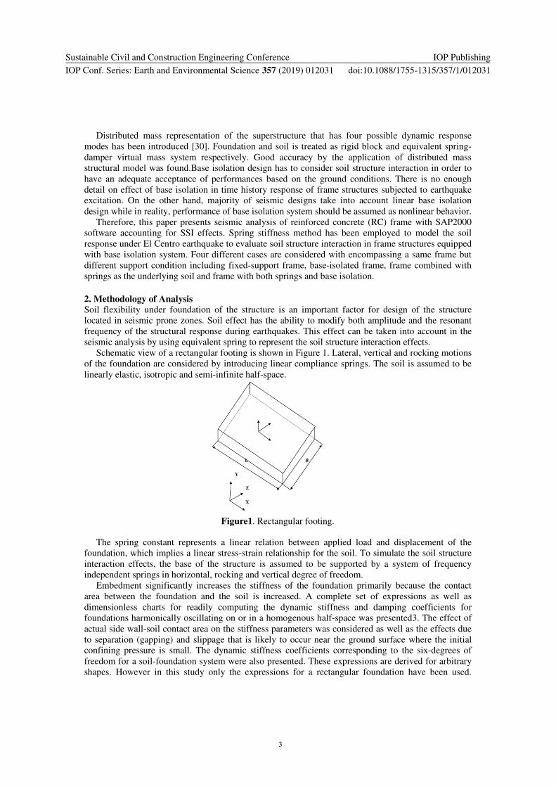
Schematic view of a rectangular footing is shown in Figure 1. Lateral, vertical and rocking motions
of the foundation are considered by introducing linear compliance springs. The soil is assumed to be
linearly elastic, isotropic and semi-infinite half-space.
Figure1. Rectangular footing.
The spring constant represents a linear relation between applied load and displacement of the
foundation, which implies a linear stress-strain relationship for the soil. To simulate the soil structure
interaction effects, the base of the structure is assumed to be supported by a system of frequency
independent springs in horizontal, rocking and vertical degree of freedom.
Embedment significantly increases the stiffness of the foundation primarily because the contact
area between the foundation and the soil is increased. A complete set of expressions as well as
dimensionless charts for readily computing the dynamic stiffness and damping coefficients for
foundations harmonically oscillating on or in a homogenous half-space was presented3. The effect of
actual side wall-soil contact area on the stiffness parameters was considered as well as the effects due
to separation (gapping) and slippage that is likely to occur near the ground surface where the initial
confining pressure is small. The dynamic stiffness coefficients corresponding to the six-degrees of
freedom for a soil-foundation system were also presented. These expressions are derived for arbitrary
shapes. However in this study only the expressions for a rectangular foundation have been used.
Sustainable Civil and Construction Engineering Conference
IOP Conf. Series: Earth and Environmental Science 357 (2019) 012031
IOP Publishing
doi:10.1088/1755-1315/357/1/012031
4
Components of spring stiffness which represent the underlying soil are tabulated in Table 1.
Table1.Stiffness for a rigid plate on a semi infinite homogeneous elastic half space3.
Stiffness parameters Rigid Plate Stiffness at Surface
Vertical Translation )8.0)(55.1(1
75.00+
−=
B
L
v
GBK vy
Horizontal Translation
(along X direction) )2.1)(4.3(
2
65.00+
−=
B
L
v
GBK HX
Horizontal Translation
(along Z direction) )8.04.0)(4.3(
2
65.00++
−=
B
L
B
L
v
GBK HZ
Rotation about Z axis )1.04.0(1
30
+−
=B
L
v
GBK RX
Rotation about X axis )034.0)(47.0(1
4.23
0+
−=
B
L
v
GBK RZ
Torsion 51.0)(53.0(45.20
+=B
LGBK RY
As shown in Table 1, G is shear modulus, B is width of footing, L stands for length of the footing
and � is poisons ratio. K0HX, K0VY and K0HZare translations along X, Y and Z directions
respectively. K0RXrepresents for rotation about X axes, K0RZ is rotation about Z axes and K0RY is
torsion. The shear modulus (G) can be obtained from the shear wave velocity (Vs) and the mass
density of the soil (ρ) as:
G = �.(Vs)2 (1)
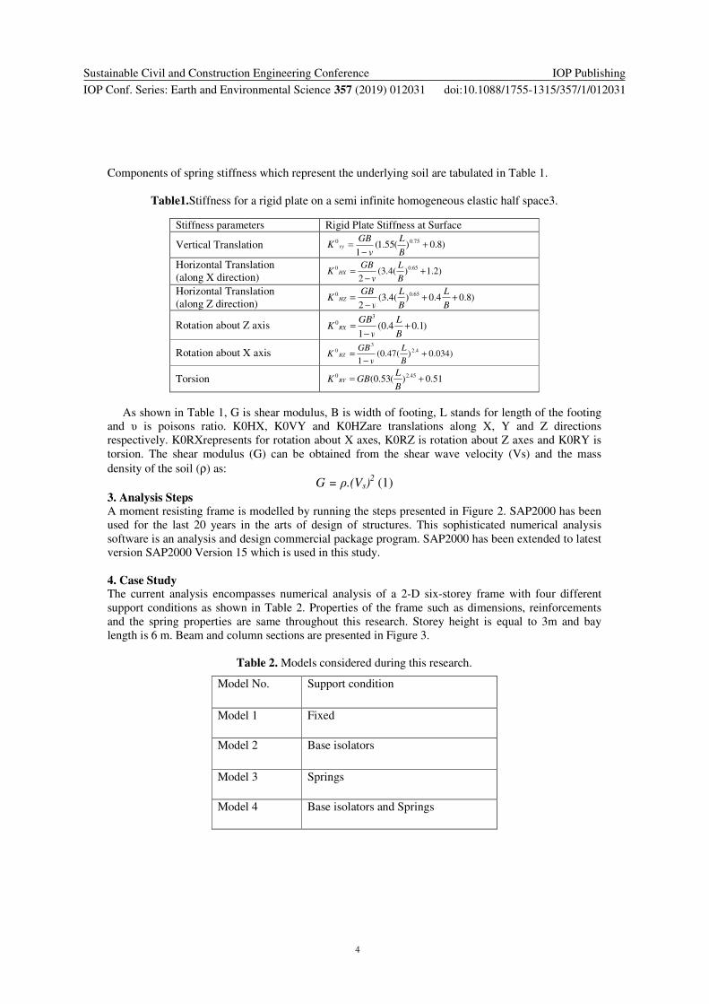
3. Analysis Steps A moment resisting frame is modelled by running the steps presented in Figure 2. SAP2000 has been
used for the last 20 years in the arts of design of structures. This sophisticated numerical analysis
software is an analysis and design commercial package program. SAP2000 has been extended to latest
version SAP2000 Version 15 which is used in this study.
4. Case Study The current analysis encompasses numerical analysis of a 2-D six-storey frame with four different
support conditions as shown in Table 2. Properties of the frame such as dimensions, reinforcements
and the spring properties are same throughout this research. Storey height is equal to 3m and bay
length is 6 m. Beam and column sections are presented in Figure 3.
Table 2. Models considered during this research.
Model No. Support condition
Model 1 Fixed
Model 2 Base isolators
Model 3 Springs
Model 4 Base isolators and Springs
Sustainable Civil and Construction Engineering Conference
IOP Conf. Series: Earth and Environmental Science 357 (2019) 012031
IOP Publishing
doi:10.1088/1755-1315/357/1/012031
5
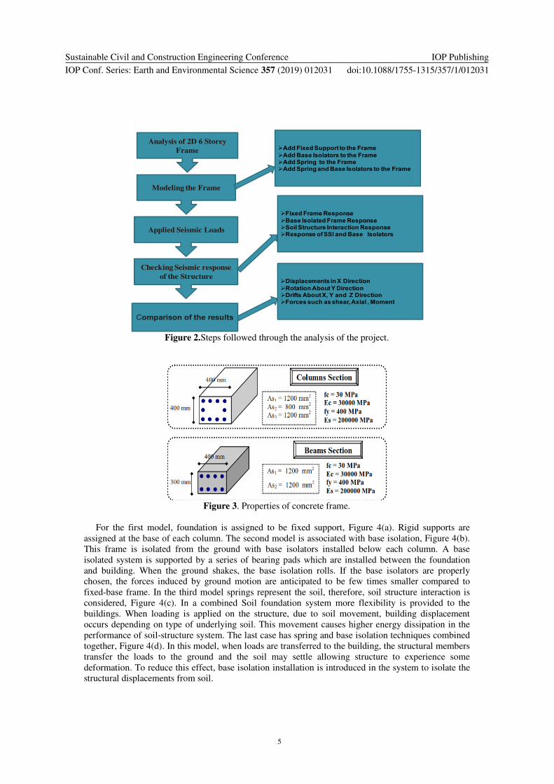
Figure 2.Steps followed through the analysis of the project.
Figure 3. Properties of concrete frame.
For the first model, foundation is assigned to be fixed support, Figure 4(a). Rigid supports are
assigned at the base of each column. The second model is associated with base isolation, Figure 4(b).
This frame is isolated from the ground with base isolators installed below each column. A base
isolated system is supported by a series of bearing pads which are installed between the foundation
and building. When the ground shakes, the base isolation rolls. If the base isolators are properly
chosen, the forces induced by ground motion are anticipated to be few times smaller compared to
fixed-base frame. In the third model springs represent the soil, therefore, soil structure interaction is
considered, Figure 4(c). In a combined Soil foundation system more flexibility is provided to the
buildings. When loading is applied on the structure, due to soil movement, building displacement
occurs depending on type of underlying soil. This movement causes higher energy dissipation in the
performance of soil-structure system. The last case has spring and base isolation techniques combined
together, Figure 4(d). In this model, when loads are transferred to the building, the structural members
transfer the loads to the ground and the soil may settle allowing structure to experience some
deformation. To reduce this effect, base isolation installation is introduced in the system to isolate the
structural displacements from soil.
Analysis of 2D 6 Storey
Frame
Modeling the Frame
Applied Seismic Loads
Checking Seismic response
of the Structure
�Add Fixed Support to the Frame
�Add Base Isolators to the Frame �Add Spring to the Frame�Add Spring and Base Isolators to the Frame
�Fixed Frame Response
�Base Isolated Frame Response�Soil Structure Interaction Response�Response of SSI and Base Isolators
Comparison of the results
�Displacements in X Direction
�Rotation About Y Direction�Drifts About X, Y and Z Direction�Forces such as shear, Axial , Moment
Sustainable Civil and Construction Engineering Conference
IOP Conf. Series: Earth and Environmental Science 357 (2019) 012031
IOP Publishing
doi:10.1088/1755-1315/357/1/012031
6
(a) (b)
(c) (d)
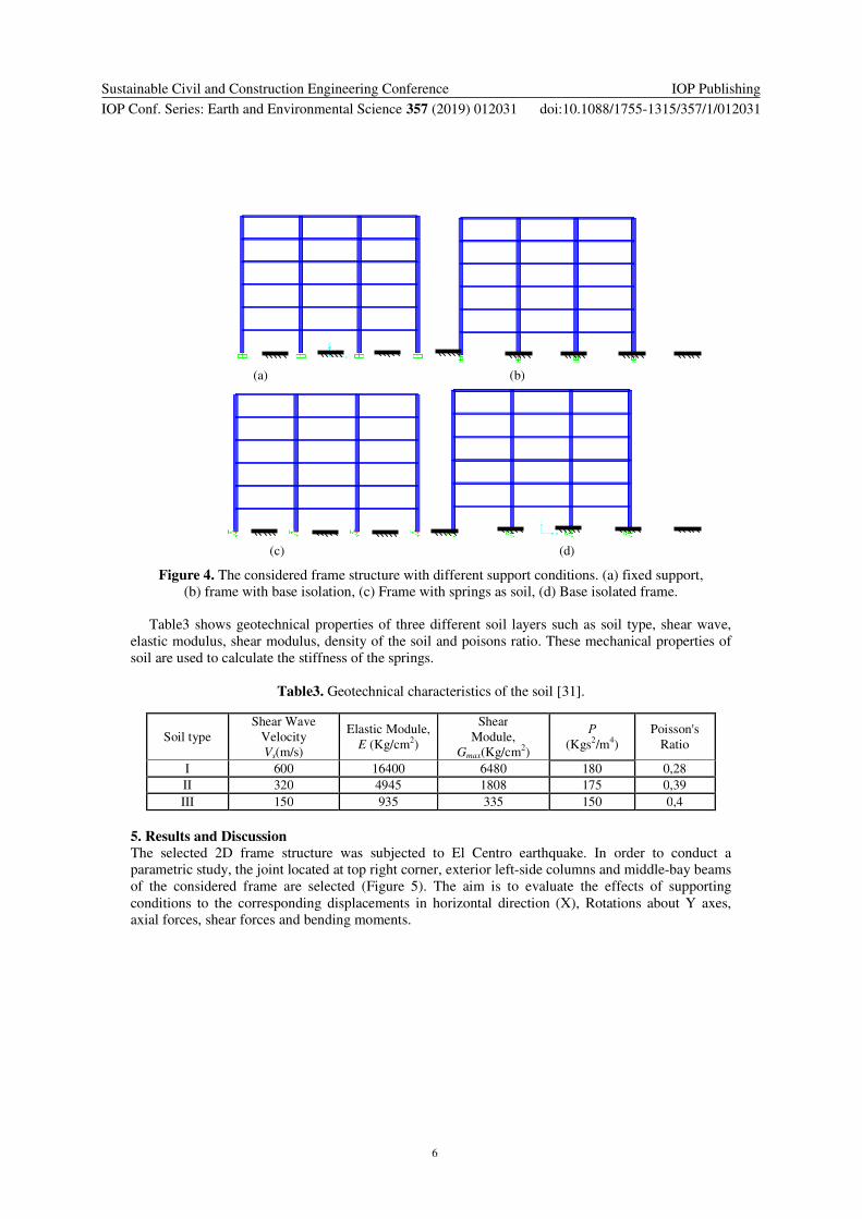
Figure 4. The considered frame structure with different support conditions. (a) fixed support,
(b) frame with base isolation, (c) Frame with springs as soil, (d) Base isolated frame.
Table3 shows geotechnical properties of three different soil layers such as soil type, shear wave,
elastic modulus, shear modulus, density of the soil and poisons ratio. These mechanical properties of
soil are used to calculate the stiffness of the springs.
Table3. Geotechnical characteristics of the soil [31].
Soil type
Shear Wave
Velocity
Vs(m/s)
Elastic Module,
E (Kg/cm2)
Shear
Module,
Gmax(Kg/cm2)
�
(Kgs2/m
4)
Poisson's
Ratio
I 600 16400 6480 180 0,28
II 320 4945 1808 175 0,39
III 150 935 335 150 0,4
5. Results and Discussion
The selected 2D frame structure was subjected to El Centro earthquake. In order to conduct a
parametric study, the joint located at top right corner, exterior left-side columns and middle-bay beams
of the considered frame are selected (Figure 5). The aim is to evaluate the effects of supporting
conditions to the corresponding displacements in horizontal direction (X), Rotations about Y axes,
axial forces, shear forces and bending moments.
Sustainable Civil and Construction Engineering Conference
IOP Conf. Series: Earth and Environmental Science 357 (2019) 012031
IOP Publishing
doi:10.1088/1755-1315/357/1/012031
7
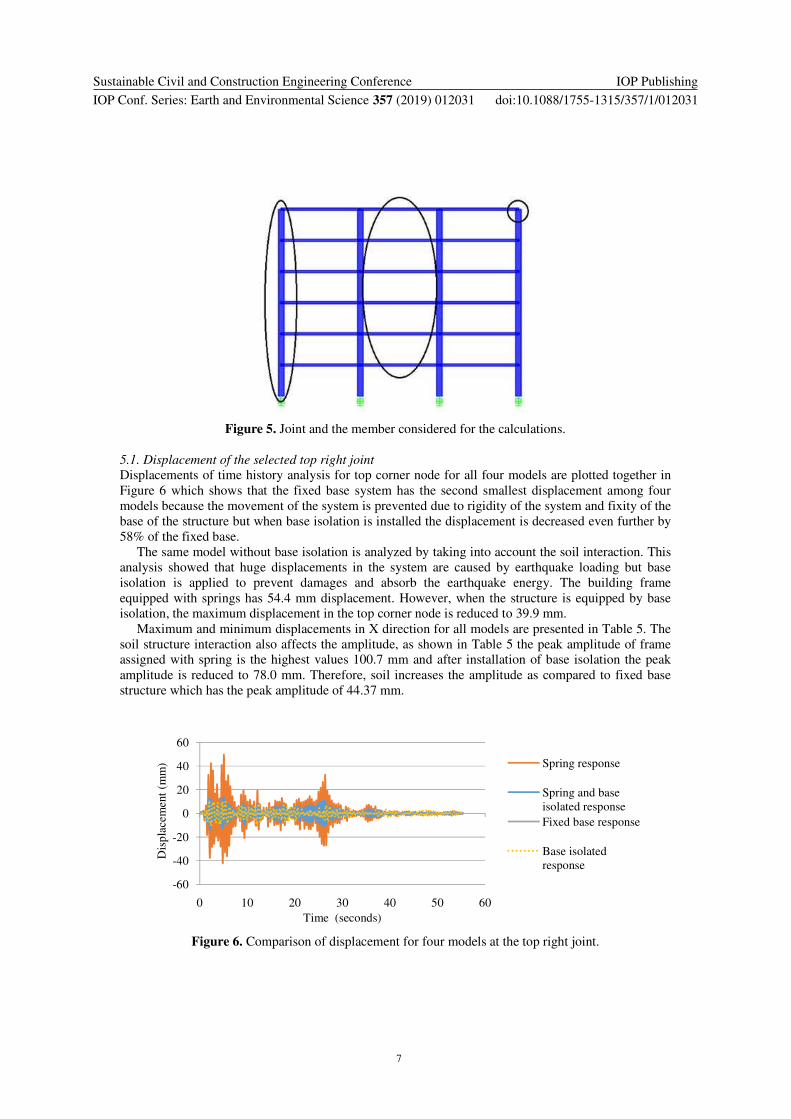
Figure 5. Joint and the member considered for the calculations.
5.1. Displacement of the selected top right joint
Displacements of time history analysis for top corner node for all four models are plotted together in
Figure 6 which shows that the fixed base system has the second smallest displacement among four
models because the movement of the system is prevented due to rigidity of the system and fixity of the
base of the structure but when base isolation is installed the displacement is decreased even further by
58% of the fixed base.
The same model without base isolation is analyzed by taking into account the soil interaction. This
analysis showed that huge displacements in the system are caused by earthquake loading but base
isolation is applied to prevent damages and absorb the earthquake energy. The building frame
equipped with springs has 54.4 mm displacement. However, when the structure is equipped by base
isolation, the maximum displacement in the top corner node is reduced to 39.9 mm.
Maximum and minimum displacements in X direction for all models are presented in Table 5. The
soil structure interaction also affects the amplitude, as shown in Table 5 the peak amplitude of frame
assigned with spring is the highest values 100.7 mm and after installation of base isolation the peak
amplitude is reduced to 78.0 mm. Therefore, soil increases the amplitude as compared to fixed base
structure which has the peak amplitude of 44.37 mm.
Figure 6. Comparison of displacement for four models at the top right joint.
-60
-40
-20
0
20
40
60
0 10 20 30 40 50 60
Spring response
Spring and base
isolated response
Fixed base response
Base isolated
response
Dis
pla
cem
ent
(mm
)
Time (seconds)
Sustainable Civil and Construction Engineering Conference
IOP Conf. Series: Earth and Environmental Science 357 (2019) 012031
IOP Publishing
doi:10.1088/1755-1315/357/1/012031
8
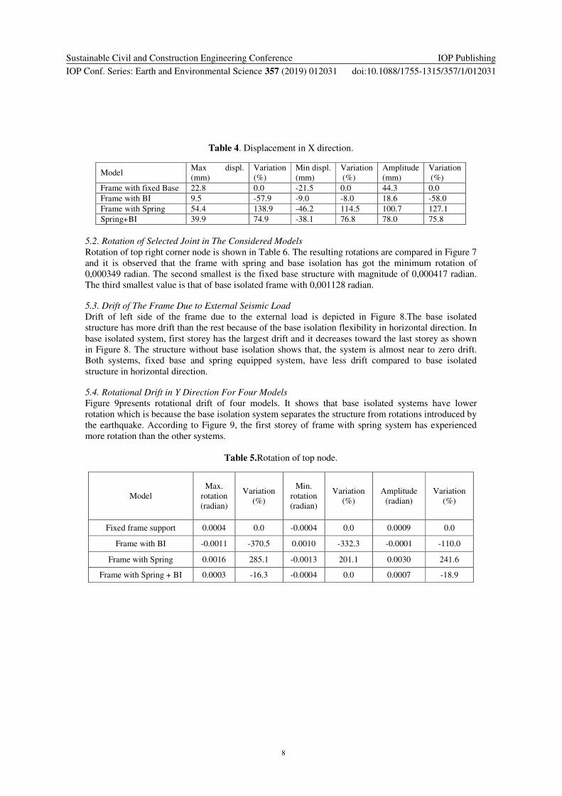
Table 4. Displacement in X direction.
Model Max displ.
(mm)
Variation
(%)
Min displ.
(mm)
Variation
(%)
Amplitude
(mm)
Variation
(%)
Frame with fixed Base 22.8 0.0 -21.5 0.0 44.3 0.0
Frame with BI 9.5 -57.9 -9.0 -8.0 18.6 -58.0
Frame with Spring 54.4 138.9 -46.2 114.5 100.7 127.1
Spring+BI 39.9 74.9 -38.1 76.8 78.0 75.8
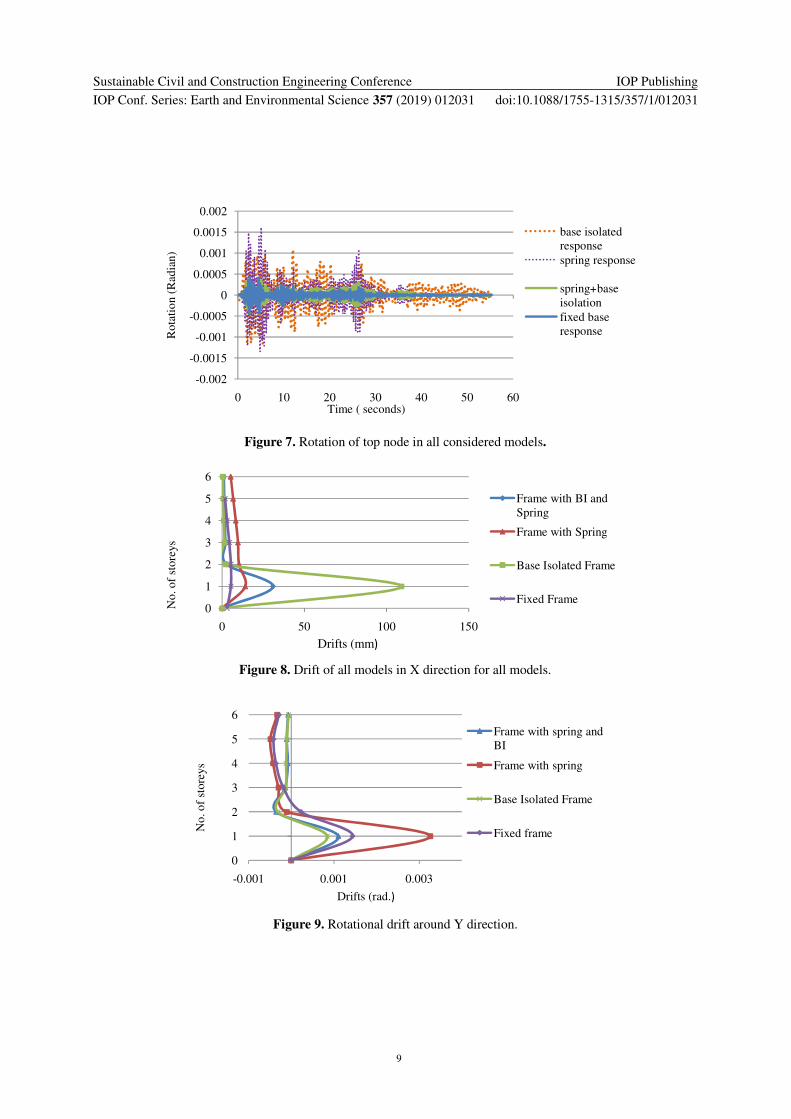
5.2. Rotation of Selected Joint in The Considered Models
Rotation of top right corner node is shown in Table 6. The resulting rotations are compared in Figure 7
and it is observed that the frame with spring and base isolation has got the minimum rotation of
0,000349 radian. The second smallest is the fixed base structure with magnitude of 0,000417 radian.
The third smallest value is that of base isolated frame with 0,001128 radian.
5.3. Drift of The Frame Due to External Seismic Load
Drift of left side of the frame due to the external load is depicted in Figure 8.The base isolated
structure has more drift than the rest because of the base isolation flexibility in horizontal direction. In
base isolated system, first storey has the largest drift and it decreases toward the last storey as shown
in Figure 8. The structure without base isolation shows that, the system is almost near to zero drift.
Both systems, fixed base and spring equipped system, have less drift compared to base isolated
structure in horizontal direction.
5.4. Rotational Drift in Y Direction For Four Models
Figure 9presents rotational drift of four models. It shows that base isolated systems have lower
rotation which is because the base isolation system separates the structure from rotations introduced by
the earthquake. According to Figure 9, the first storey of frame with spring system has experienced
more rotation than the other systems.
Table 5.Rotation of top node.
Model
Max.
rotation
(radian)
Variation
(%)
Min.
rotation
(radian)
Variation
(%)
Amplitude
(radian)
Variation
(%)
Fixed frame support 0.0004 0.0 -0.0004 0.0 0.0009 0.0
Frame with BI -0.0011 -370.5 0.0010 -332.3 -0.0001 -110.0
Frame with Spring 0.0016 285.1 -0.0013 201.1 0.0030 241.6
Frame with Spring + BI 0.0003 -16.3 -0.0004 0.0 0.0007 -18.9
Sustainable Civil and Construction Engineering Conference
IOP Conf. Series: Earth and Environmental Science 357 (2019) 012031
IOP Publishing
doi:10.1088/1755-1315/357/1/012031
9
Figure 7. Rotation of top node in all considered models.
Figure 8. Drift of all models in X direction for all models.
Figure 9. Rotational drift around Y direction.
-0.002
-0.0015
-0.001
-0.0005
0
0.0005
0.001
0.0015
0.002
0 10 20 30 40 50 60
base isolated
response
spring response
spring+base
isolation
fixed base
response
Time ( seconds)
Rota
tio
n (
Rad
ian)
0
1
2
3
4
5
6
0 50 100 150
Frame with BI and
Spring
Frame with Spring
Base Isolated Frame
Fixed Frame
Drifts (mm�
No. of
store
ys
0
1
2
3
4
5
6
-0.001 0.001 0.003
Frame with spring and
BI
Frame with spring
Base Isolated Frame
Fixed frame
Drifts (rad.�
No
. o
f st
ore
ys
Sustainable Civil and Construction Engineering Conference
IOP Conf. Series: Earth and Environmental Science 357 (2019) 012031
IOP Publishing
doi:10.1088/1755-1315/357/1/012031
10
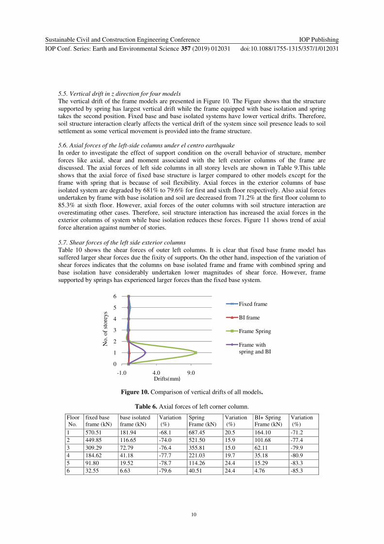
5.5. Vertical drift in z direction for four models
The vertical drift of the frame models are presented in Figure 10. The Figure shows that the structure
supported by spring has largest vertical drift while the frame equipped with base isolation and spring
takes the second position. Fixed base and base isolated systems have lower vertical drifts. Therefore,
soil structure interaction clearly affects the vertical drift of the system since soil presence leads to soil
settlement as some vertical movement is provided into the frame structure.
5.6. Axial forces of the left-side columns under el centro earthquake
In order to investigate the effect of support condition on the overall behavior of structure, member
forces like axial, shear and moment associated with the left exterior columns of the frame are
discussed. The axial forces of left side columns in all storey levels are shown in Table 9.This table
shows that the axial force of fixed base structure is larger compared to other models except for the
frame with spring that is because of soil flexibility. Axial forces in the exterior columns of base
isolated system are degraded by 681% to 79.6% for first and sixth floor respectively. Also axial forces
undertaken by frame with base isolation and soil are decreased from 71.2% at the first floor column to
85.3% at sixth floor. However, axial forces of the outer columns with soil structure interaction are
overestimating other cases. Therefore, soil structure interaction has increased the axial forces in the
exterior columns of system while base isolation reduces these forces. Figure 11 shows trend of axial
force alteration against number of stories.
5.7. Shear forces of the left side exterior columns
Table 10 shows the shear forces of outer left columns. It is clear that fixed base frame model has
suffered larger shear forces due the fixity of supports. On the other hand, inspection of the variation of
shear forces indicates that the columns on base isolated frame and frame with combined spring and
base isolation have considerably undertaken lower magnitudes of shear force. However, frame
supported by springs has experienced larger forces than the fixed base system.
Figure 10. Comparison of vertical drifts of all models.
Table 6. Axial forces of left corner column.
Floor
No.
fixed base
frame (kN)
base isolated
frame (kN)
Variation
(%)
Spring
Frame (kN)
Variation
(%)
BI+ Spring
Frame (kN)
Variation
(%)
1 570.51 181.94 -68.1 687.45 20.5 164.10 -71.2
2 449.85 116.65 -74.0 521.50 15.9 101.68 -77.4
3 309.29 72.79 -76.4 355.81 15.0 62.11 -79.9
4 184.62 41.18 -77.7 221.03 19.7 35.18 -80.9
5 91.80 19.52 -78.7 114.26 24.4 15.29 -83.3
6 32.55 6.63 -79.6 40.51 24.4 4.76 -85.3
0
1
2
3
4
5
6
-1.0 4.0 9.0
Fixed frame
BI frame
Frame Spring
Frame with
spring and BI
Drifts(mm�
No. of
store
ys

Sustainable Civil and Construction Engineering Conference
IOP Conf. Series: Earth and Environmental Science 357 (2019) 012031
IOP Publishing
doi:10.1088/1755-1315/357/1/012031
11
Figure 11. Axial forces of left corner column.
Table 7. Shear forces of left exterior columns.
Floor
No
fixed base
frame(kN)
base isolated
frame(kN)
Variation
(%)
spring
frame(kN)
Variation
(%)
BI+ Spring
frame(kN)
Variation
(%)
6 230.72 63.12 -72.6 322.43 39.7 75.81 -67.1
5 186.92 58.74 -68.5 189.00 1.1 26.17 -86.0
4 157.76 43.39 -72.5 175.78 11.4 23.05 -85.3
3 120.38 38.37 -68.1 129.36 7.4 22.41 -81.3
2 80.90 16.45 -79.6 85.88 6.1 19.66 -75.7
1 25.90 9.17 -64.5 17.17 -33.7 4.82 -81.3
Figure 12 shows the shear force graph plotted against number of storey. It is shown that the spring-
equipped frame has been subjected to larger shear forces compared to fixed base frame, base isolated
frame and frame with base isolation and spring.
Figure 12. Comparison of moment of left corner columns.
5.8. Moments of the exterior left side columns
Table 11 indicates variation of moments of exterior columns at the left side of the frame. It isfound
that those columns at the two lower storey levels in frame with base isolation experience less force
0.00 200.00 400.00 600.00 800.00
1
2
3
4
5
6
Frame with spring and base
isolationBase isolated
Fixed base frame
Frame with springSto
rey l
evel
Axial forces (kN)
0.00 200.00 400.00 600.00 800.00
1
2
3
4
5
6
Frame with Spring and BI
Frame with Spring
Base Isolated Frame
Fixed base frame
Sto
rey
num
ber
Moments (kN.mm)
Sustainable Civil and Construction Engineering Conference
IOP Conf. Series: Earth and Environmental Science 357 (2019) 012031
IOP Publishing
doi:10.1088/1755-1315/357/1/012031
12
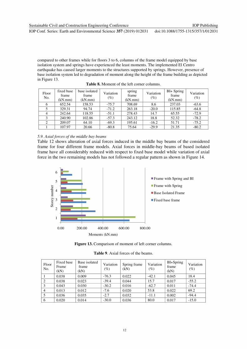
compared to other frames while for floors 3 to 6, columns of the frame model equipped by base
isolation system and springs have experienced the least moments. The implemented El Centro
earthquake has caused larger moments to the structures supported by springs. However, presence of
base isolation system led to degradation of moment along the height of the frame building as depicted
in Figure 13.
Table 8. Moment of the left corner columns.
Floor
No.
fixed base
frame
(kN.mm)
base isolated
frame
(kN.mm)
Variation
(%)
spring
frame
(kN.mm)
Variation
(%)
BI+ Spring
frame
(kN.mm)
Variation
(%)
6 652.54 158.53 -75.7 708.69 8.6 237.03 -63.6
5 329.31 94.74 -71.2 263.18 -20.0 115.85 -64.8
4 242.64 118.55 -51.1 278.43 14.7 65.55 -72.9
3 240.90 102.86 -57.3 243.12 18.8 52.32 -78.2
2 209.07 64.10 -69.3 195.61 -16.2 51.71 -75.2
1 107.97 20.66 -80.8 75.64 -29.9 21.35 -80.2
5.9. Axial forces of the middle bay beams
Table 12 shows alteration of axial forces induced in the middle bay beams of the considered
frame for four different frame models. Axial forces in middle-bay beams of based isolated
frame have all considerably reduced with respect to fixed base model while variation of axial
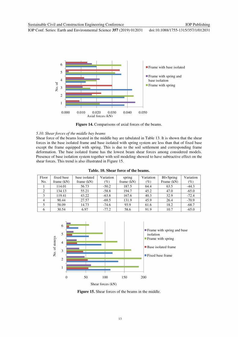
force in the two remaining models has not followed a regular pattern as shown in Figure 14.
Figure 13. Comparison of moment of left corner columns.
Table 9. Axial forces of the beams.
Floor
No.
Fixed base
Frame
(kN)
Base isolated
frame
(kN)
Variation
(%)
Spring frame
(kN)
Variation
(%)
BI+Spring
frame
(kN)
Variation
(%)
1 0.038 0.009 -76.3 0.022 -42.1 0.045 18.4
2 0.038 0.023 -39.4 0.044 15.7 0.017 -55.2
3 0.043 0.030 -30.2 0.016 -62.7 0.011 -74.4
4 0.013 0.012 -7.6 0.020 53.8 0.022 69.2
5 0.036 0.035 -2.7 0.032 -11.1 0.002 -94.4
6 0.020 0.014 -30.0 0.036 80.0 0.017 -15.0
0.00 200.00 400.00 600.00 800.00
1
2
3
4
5
6
Frame with Spring and BI
Frame with Spring
Base Isolated Frame
Fixed base frame
Sto
rey
num
ber
Moments (kN.mm)
Sustainable Civil and Construction Engineering Conference
IOP Conf. Series: Earth and Environmental Science 357 (2019) 012031
IOP Publishing
doi:10.1088/1755-1315/357/1/012031
13
Figure 14. Comparisons of axial forces of the beams.
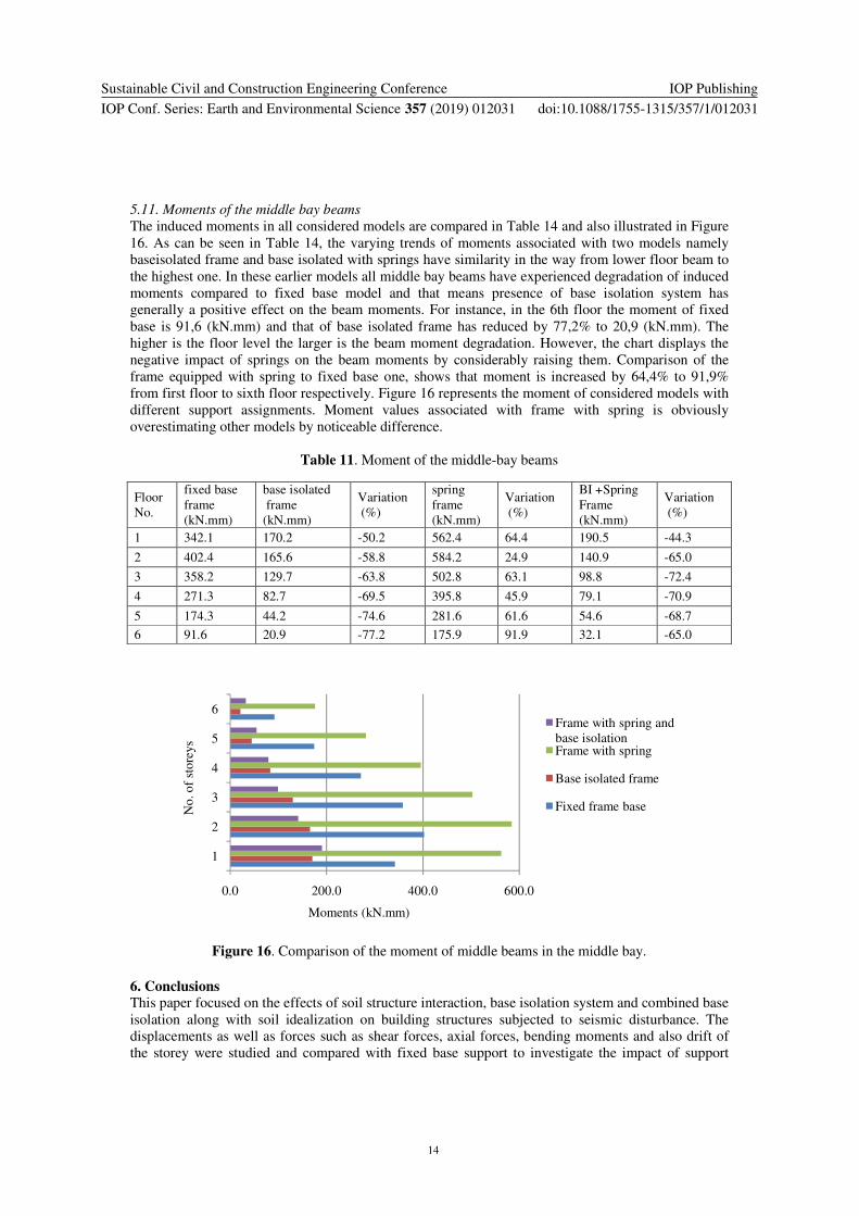
5.10. Shear forces of the middle bay beams
Shear force of the beams located in the middle bay are tabulated in Table 13. It is shown that the shear
forces in the base isolated frame and base isolated with spring system are less than that of fixed base
except the frame equipped with spring. This is due to the soil settlement and corresponding frame
deformation. The base isolated frame has the lowest beam shear forces among considered models.
Presence of base isolation system together with soil modeling showed to have subtractive effect on the
shear forces. This trend is also illustrated in Figure 15.
Table. 10. Shear force of the beams.
Floor
No.
fixed base
frame (kN)
base isolated
frame (kN)
Variation
(%)
spring
frame (kN)
Variation
(%)
BI+Spring
Frame (kN)
Variation
(%)
1 114.01 56.73 -50.2 187.5 64.4 63.5 -44.3
2 134.13 55.21 -58.8 194.7 45.2 47.0 -65.0
3 119.41 43.22 -63.8 167.6 40.3 32.9 -72.4
4 90.44 27.57 -69.5 131.9 45.9 26.4 -70.9
5 58.09 14.73 -74.6 93.9 61.6 18.2 -68.7
6 30.54 6.97 -77.2 58.6 91.9 10.7 -65.0
Figure 15. Shear forces of the beams in the middle.
0.000 0.010 0.020 0.030 0.040 0.050
1
2
3
4
5
6Frame with base isolated
Frame with spring and
base isolation
Frame with spring
Axial forces (kN)
No. of
0 50 100 150 200
1
2
3
4
5
6
Frame with spring and base
isolation
Frame with spring
Base isolated frame
Fixed base frameNo
. o
f st
ore
ys
Shear forces (kN)
Sustainable Civil and Construction Engineering Conference
IOP Conf. Series: Earth and Environmental Science 357 (2019) 012031
IOP Publishing
doi:10.1088/1755-1315/357/1/012031
14
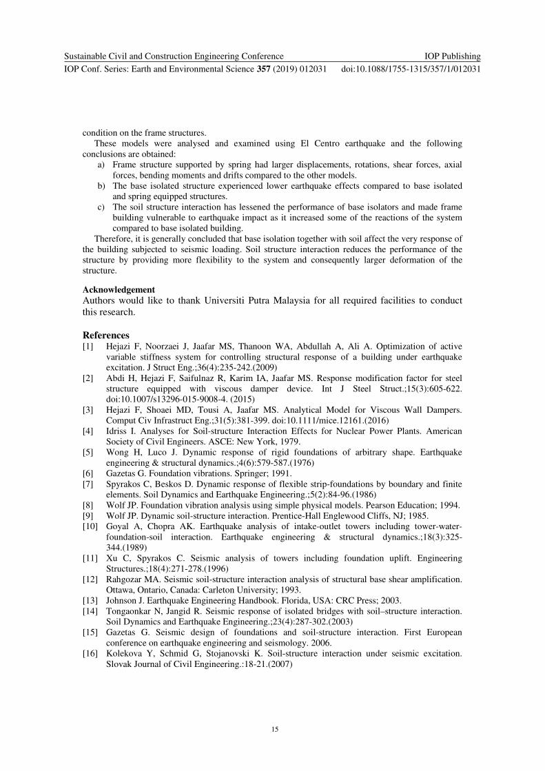
5.11. Moments of the middle bay beams
The induced moments in all considered models are compared in Table 14 and also illustrated in Figure
16. As can be seen in Table 14, the varying trends of moments associated with two models namely
baseisolated frame and base isolated with springs have similarity in the way from lower floor beam to
the highest one. In these earlier models all middle bay beams have experienced degradation of induced
moments compared to fixed base model and that means presence of base isolation system has
generally a positive effect on the beam moments. For instance, in the 6th floor the moment of fixed
base is 91,6 (kN.mm) and that of base isolated frame has reduced by 77,2% to 20,9 (kN.mm). The
higher is the floor level the larger is the beam moment degradation. However, the chart displays the
negative impact of springs on the beam moments by considerably raising them. Comparison of the
frame equipped with spring to fixed base one, shows that moment is increased by 64,4% to 91,9%
from first floor to sixth floor respectively. Figure 16 represents the moment of considered models with
different support assignments. Moment values associated with frame with spring is obviously
overestimating other models by noticeable difference.
Table 11. Moment of the middle-bay beams
Floor
No.
fixed base
frame
(kN.mm)
base isolated
frame
(kN.mm)
Variation
(%)
spring
frame
(kN.mm)
Variation
(%)
BI +Spring
Frame
(kN.mm)
Variation
(%)
1 342.1 170.2 -50.2 562.4 64.4 190.5 -44.3
2 402.4 165.6 -58.8 584.2 24.9 140.9 -65.0
3 358.2 129.7 -63.8 502.8 63.1 98.8 -72.4
4 271.3 82.7 -69.5 395.8 45.9 79.1 -70.9
5 174.3 44.2 -74.6 281.6 61.6 54.6 -68.7
6 91.6 20.9 -77.2 175.9 91.9 32.1 -65.0
Figure 16. Comparison of the moment of middle beams in the middle bay.
6. ConclusionsThis paper focused on the effects of soil structure interaction, base isolation system and combined base
isolation along with soil idealization on building structures subjected to seismic disturbance. The
displacements as well as forces such as shear forces, axial forces, bending moments and also drift of
the storey were studied and compared with fixed base support to investigate the impact of support
0.0 200.0 400.0 600.0
1
2
3
4
5
6Frame with spring and
base isolationFrame with spring
Base isolated frame
Fixed frame baseNo
. o
f st
ore
ys
Moments (kN.mm)
Sustainable Civil and Construction Engineering Conference
IOP Conf. Series: Earth and Environmental Science 357 (2019) 012031
IOP Publishing
doi:10.1088/1755-1315/357/1/012031
15
condition on the frame structures.
These models were analysed and examined using El Centro earthquake and the following
conclusions are obtained:
a) Frame structure supported by spring had larger displacements, rotations, shear forces, axial
forces, bending moments and drifts compared to the other models.
b) The base isolated structure experienced lower earthquake effects compared to base isolated
and spring equipped structures.
c) The soil structure interaction has lessened the performance of base isolators and made frame
building vulnerable to earthquake impact as it increased some of the reactions of the system
compared to base isolated building.
Therefore, it is generally concluded that base isolation together with soil affect the very response of
the building subjected to seismic loading. Soil structure interaction reduces the performance of the
structure by providing more flexibility to the system and consequently larger deformation of the
structure.
Acknowledgement
Authors would like to thank Universiti Putra Malaysia for all required facilities to conduct
this research.
References [1] Hejazi F, Noorzaei J, Jaafar MS, Thanoon WA, Abdullah A, Ali A. Optimization of active
variable stiffness system for controlling structural response of a building under earthquake
excitation. J Struct Eng.;36(4):235-242.(2009)
[2] Abdi H, Hejazi F, Saifulnaz R, Karim IA, Jaafar MS. Response modification factor for steel
structure equipped with viscous damper device. Int J Steel Struct.;15(3):605-622.
doi:10.1007/s13296-015-9008-4. (2015)
[3] Hejazi F, Shoaei MD, Tousi A, Jaafar MS. Analytical Model for Viscous Wall Dampers.
Comput Civ Infrastruct Eng.;31(5):381-399. doi:10.1111/mice.12161.(2016)
[4] Idriss I. Analyses for Soil-structure Interaction Effects for Nuclear Power Plants. American
Society of Civil Engineers. ASCE: New York, 1979.
[5] Wong H, Luco J. Dynamic response of rigid foundations of arbitrary shape. Earthquake
engineering & structural dynamics.;4(6):579-587.(1976)
[6] Gazetas G. Foundation vibrations. Springer; 1991.
[7] Spyrakos C, Beskos D. Dynamic response of flexible strip-foundations by boundary and finite
elements. Soil Dynamics and Earthquake Engineering.;5(2):84-96.(1986)
[8] Wolf JP. Foundation vibration analysis using simple physical models. Pearson Education; 1994.
[9] Wolf JP. Dynamic soil-structure interaction. Prentice-Hall Englewood Cliffs, NJ; 1985.
[10] Goyal A, Chopra AK. Earthquake analysis of intake-outlet towers including tower-water-
foundation-soil interaction. Earthquake engineering & structural dynamics.;18(3):325-
344.(1989)
[11] Xu C, Spyrakos C. Seismic analysis of towers including foundation uplift. Engineering
Structures.;18(4):271-278.(1996)
[12] Rahgozar MA. Seismic soil-structure interaction analysis of structural base shear amplification.
Ottawa, Ontario, Canada: Carleton University; 1993.
[13] Johnson J. Earthquake Engineering Handbook. Florida, USA: CRC Press; 2003.
[14] Tongaonkar N, Jangid R. Seismic response of isolated bridges with soil–structure interaction.
Soil Dynamics and Earthquake Engineering.;23(4):287-302.(2003)
[15] Gazetas G. Seismic design of foundations and soil-structure interaction. First European
conference on earthquake engineering and seismology. 2006.
[16] Kolekova Y, Schmid G, Stojanovski K. Soil-structure interaction under seismic excitation.
Slovak Journal of Civil Engineering.:18-21.(2007)
Sustainable Civil and Construction Engineering Conference
IOP Conf. Series: Earth and Environmental Science 357 (2019) 012031
IOP Publishing
doi:10.1088/1755-1315/357/1/012031
16
[17] Pecker A, Paolucci R, Chatzigogos C, Correia AA, Figini R. The role of non-linear dynamic
soil-foundation interaction on the seismic response of structures. Bulletin of Earthquake
Engineering.:1-20.(2013)
[18] Kelly JM, Naeim F. Design of seismic isolated structures: From theory to practice. Nueva York,
John Wiley & Sons. 1999.
[19] Komodromos P, Stiemer S. Seismic isolation for earthquake resistant structures. Applied
Mechanics Reviews.;54:112.(2001)
[20] Skinner RI, Robinson WH, McVerry GH. An introduction to seismic isolation. USA, New
York: Wiley; 1993.
[21] International Building Code. Dearborn Trade Publishing; 2000.
[22] Eurocode 8: Design of structures for earthquake resistance. 1990.
[23] Iemura H, Pradono MH. Passive and semi-active seismic response control of a cable-stayed
bridge. Journal of Structural Control.;9(3):189-204.(2002)
[24] Spyrakos C, Maniatakis CA, Koutromanos I. Soil–structure interaction effects on base-isolated
buildings founded on soil stratum. Engineering Structures.;31(3):729-737.(2009)
[25] Gueguen P. Experimental analysis of the seismic response of one base-isolation building
according to different levels of shaking: example of the Martinique earthquake (2007/11/29)
Mw 7.3. Bulletin of Earthquake Engineering.;10(4):1285-1298.(2012)
[26] Jacob M, Dodagoudar G, Matsagar V. Seismic Reliability Analysis of Base-Isolated Buildings.
Proceedings of the International Symposium on Engineering under Uncertainty: Safety
Assessment and Management (ISEUSAM-2012). Springer: India,; 1251-1265.(2013)
[27] Chaudhary M, Abe M, Fujino Y. Identification of soil–structure interaction effect in base-
isolated bridges from earthquake records. Soil Dynamics and Earthquake
Engineering.;21(8):713-725.(2001)
[28] Spyrakos C, Vlassis A. Effect of soil-structure interaction on seismically isolated bridges.
Journal of earthquake engineering.;6(03):391-429.(2002)
[29] Vlassis A, Spyrakos C. Seismically isolated bridge piers on shallow soil stratum with soil–
structure interaction. Computers & structures.;79(32):2847-2861.(2001)
[30] Manolis GD, Markou A. A distributed mass structural system for soil-structure-interaction and
base isolation studies. Archive of Applied Mechanics.;82(10-11):1513-1529.(2012)
[31] Tabatabaiefar HR, Massumi A. A simplified method to determine seismic responses of
reinforced concrete moment resisting building frames under influence of soil–structure
interaction. Soil Dynamics and Earthquake Engineering.;30(11):1259-1267.