paper number - controls, measurement & calibration...
TRANSCRIPT

Speakers Information- Controls, Measurement & Calibration Congress
HiL-Application and Model-Based Development – The Future!!
Robert Strasser, Gabor Hrauda, Johann WurzenbergerAVL List GmbH
Christian Roduner, Diego Valero-BertrandAVL Software & Functions GmbH
ABSTRACT
Innovative real-time capable plant models – enabling even crank-angle resolved simulation – open up new perspectives and offer new possibilities for model-based development approaches. Model-based development is a measure of quality assurance and helps to reduce development time as well as cost. In case of engine control algorithm development the model-based approach comprises different phases: In the concept phase the control system is developed by means of a MiL (“Model-in-the-Loop”) environment whereas the further development and test of the hardware ECS (engine control system) is done in the HiL (“Hardware-in-the-Loop”) environment with the same engine plant model in a seamless way. The XIL.STATIONTM offers the same user interface and methodology as existing engine test facilities merging simulation world and testing world. One example of a model-based ECS development is the successful development of a control system of a genset gas engine by means of a physics-based engine model.
1. INTRODUCTION
Compliance with current and future emission regulations, attainability of maximum energy efficiency and system complexity are huge challenges for the development of powertrain and energy systems. Especially for large engines with their particular boundary conditions in the development process, the introduction and the continuous improvement of the model-based development methodology are priority objectives in order to meet the identified challenges.
Innovative model-based development approaches and XiL application have many advantages and facilitate the significant reduction of development time and cost.
The high degree of innovation results from several factors and their optimum interaction:
Embedding of the model-based methodology into the development process in order to have a seamless continuity from the first simulation task in the concept phase up to start of production or even up to the monitoring of the operation of engines in real-life operation
Multi-domain real-time platform for the creation of innovative models which fulfil the requirements in view of model fidelity and real-time capability for system simulation and for the application on HiL systems according to AVL’s principles of the Integrated and Open Development Platform
Instrumentation and test systems merging the testing world and the simulation world. They should provide the ability to use optionally the hardware component or the corresponding real-time model as a subsystem within the overall powertrain system to take full advantage of the model-based development approach (e.g. AVL XIL.STATIONTM)
{The “body” text portion should be organized using styles named Head1 and Body. Subheadings within a section should be all capital letters, run into the paragraph with normal paragraph indention. Do not leave a line of space above and below this heading. Sub-subheadings should be typed in capital and lower case letters, underscored, indented and run into the paragraph. Again, do not leave a line of space above or below this heading. (See examples below.) After you select and delete this paragraph, start entering the text for your paper here.}

2. MODEL-BASED DEVELOPMENT FOR LARGE ENGINES
In the automotive world model-based development methodology has already been enforced due to various benefits. The idea is to replace hardware components by simulation models in the development process in order to reduce time and cost.
Especially for large engine development the model-based development approaches are promising due to some reasons:
Limited availability of prototype engines: In most cases a prototype is available only in advanced stages of development. Hence, front loading as well as simultaneous engineering is possible by means of the use of appropriate engine plant models.
Combustion development with single-cylinder engines are preferred in view of reducing the testing effort. The knowledge of single cylinder test results and the projection on a corresponding multi-cylinder model enable the shifting of development activities to earlier stages by means of model-based development approaches.
Cost and effort of test-bed operation of large engines are generally high. Just the fuel costs can exceed thousands of Euros per hour. Consequently, the replacement of engine tests can lead to financial benefit.
Limited possibilities of real-life testing before commissioning of ships, mining trucks, locomotives and power plants: Virtual validation and homologation by means of system simulation offers new possibilities (e.g. simulation of real-life cycles, missions and operating profiles and prediction of performance, efficiency and emissions).
Consequently, there are numerous advantages:
Significant reduction of development time and cost No prototype engines are required for control-system development ECS with high maturity is available already at first engine start No risk of damage of engine components Worst case scenarios can be tested - that’s even with engine tests not always possible (high-altitude operation,
ambient conditions, operating scenarios, fuel quality etc.) Model-based development is a measure of quality assurance as an early failure detection is ensured Many tasks can be processed: function and algorithm development, software generation and ECS integration, testing
and validation in MiL and HiL environment, pre-calibration of functions, system investigation by integrated simulation Re-use of models for different tasks and in different project phases
3. INNOVATIVE PLANT MODELS FOR XIL-APPLICATION
In the virtual world engine models are indispensable components in the system analysis to investigate interactions between subsystems and to optimize the interaction of these systems (engine, control system, transmission, driver/operator, operating strategies, information technology, and traffic environment). Various models with different features are used in different development stages for a variety of fields of application. The simplest types of engine models are characteristic curves or maps, an increase of the model depth can be obtained by using intelligent neural networks, surrogates, mean-value approaches for cylinders as well as gas path and crank-angle resolved simulation models considering gas dynamics in the gas path. A detailed description of types of engine models is given in 1.
In general, the degree of model depth is contrary to the calculation speed. Improved solver technology, numerically optimized algorithms and computers with increased CPU frequency allow high calculation speed even for models with high model depth such as crank-angle resolved simulation models considering gas dynamics in the gas path. The ability to simulate models with higher level of detail in real time, opens up new fields of application and consideration of engine phenomena which could not be taken into account up to now.
The recently launched multi-disciplinary real-time simulation platform AVL CRUISE M offers highest flexibility and modularity in combination with “true” real-time capability for HiL application. This means that not only the average real-time factor has to be lower than 1, but also each simulation step has to be simulated significantly faster than in real time in order to avoid real-time violations. (For control-system development a minimum sampling rate of 1 kHz is required.)

3.1. Multi-Disciplinary System Simulation (CRUISE M)
The multi-disciplinary system simulation platform AVL CRUISE M is designed for model-based system development, seamlessly integrating high-quality, real-time capable subsystem models of engine, driveline, 1D fluid flow, aftertreatment, electrical and control system domains. The goal is to support development with an integrative, open and consistent simulation approach, enabling the re-use of high-quality models. Besides traditional system engineering office applications, AVL CRUISE M Engine introduces seamless control function development and calibration from MiL to SiL to HiL. Modularity with scalable model fidelity and an open integration concept enable the re-use of highly mature, real-time capable office models in an advanced model-based system development approach.
Plant modeling for control-function development and calibration needs to fulfill a list of key requirements discussed in the following paragraphs:
Multi-physical simulation tools are capable of comprising different physical phenomena taking place in the different domains by dedicated models. The different time-constants (comparing the time span required for oil heat-up, boost pressure build-up, in-cylinder combustion, fuel injection etc.) given by the physics of the individual domains are considered by dedicated numerical methods. Especially the application of tailored co-simulations featuring individual time integration rates together with conservative coupling techniques allows running numerically highly efficient models with real-time capability, as this is a key requirement to support HiL based activities.
Consistent plant modeling is essential to support the development process from the early concept phase to the late function development and calibration phase. Model consistency enables the handshake between different development teams using the same or even different tools. CRUISE M supports these ideas in both ways. Real-time capable models used during the concept phase are ready to be used, typically with a refined parameterization, in HiL application. The cross-tool consistency is given by applying identical models, featuring identical parameters and results for compressor, turbine, air cleaner, intercooler and cylinder as used in the classical thermodynamic simulation code BOOST. CRUISE M is also linked to the established 1D-3D aftertreatment simulation workflow between 1D-BOOST and 3D-FIRE using the identical description for chemical reaction, heat and mass transfer. This consistent handling of models and model parameters additionally allows a thorough tracking of model changes during its lifetime in the development process.
Scalable plant modeling in an overall framework is the answer to requirements that also scale throughout the development process. The early concept phase of the development, typically lacking detailed specifications, is best supported by physical based plant models requiring a minimum amount of input data. The later design phase requires models sensitive to more detailed input data such as valve timings, cylinder-deactivation, multi-fuel blends etc. in order to support design decisions with a proper level of fidelity. Highly accurate and computational efficient models are a must for HiL based development activities. Here the requirement accuracy is reached by improving the parameterization of a given model structure with the help of test-bed data. CRUISE M addresses the needs of the different development phases by a tailored combination of first order principles, physical, semi-physical and fully empirical approaches. Here it turned out that models featuring a maximum physical depth running in real time are the best choice.
Open and integrative simulation platforms aim, amongst others, to maintain existing models from different tools by enabling co-simulations or model-exchange. CRUISE M supports this openness by offering 3rd party tool specific and standardized interfaces for import and export. The standardized import interface is based on FMI (Functional Mockup Interface). It is e.g. chosen to embed customized cylinder and exhaust aftertreatment models into the gas path network. The export of models into other simulation environments is also based on the FMI standard. During the export, a compile step is additionally applied in order to comply with operating system (Windows, Linux, QNX) requirements given by office (ETAS Intecrio, ASCET, Simulink), HiL (ETAS, dSPACE, NI-Veristand) and test-bed (PUMA) environments.

3.2. Advantages of Physics-Based Engine Models and Crank-Angle Resolved Real-Time Simulation
The effort for creating a sufficient database of measurement data as well as for the training of surrogates may be rather high; consequently, the creation of semi-physical and fully empirical models could be difficult or even impossible for large engines as the availability of measurement data is limited. Under these circumstances innovative physics-based real-time engine models are of special interest for large engines as the availability of measurement data is no mandatory requirement for the model setup.
Attributes of physics-based models:
Crank-angle resolved simulation of gas-exchange process and high-pressure cycle in cylinders in real time Consideration of 0D gas dynamics in the gas path allows the description of torque pulsations and pulsations of mass
flow, pressure and temperature in the gas path in real time Extrapolation of actual engine‘s operating range possible due to description of components by first order principles Effort for model setup similar as for models for classical thermodynamic cycle simulation Predictability of the engine performance according to first order principles / accuracy similar to thermodynamic cycle
simulation Hardware changes considered by modification of components in the model (modularity, flexibility) Possibility of use of advanced phenomenological models (hydraulic rail model, 0D combustion models, knock models
etc.) in real time
Many phenomena can only be described by crank-angle resolved simulation whereas mean-value models are doomed to failure:
Description of discontinuous gas exchange (e.g. scavenging effects, reverse mass flow, Miller & Atkinson cycle, internal EGR, variable valve timing etc.)
EGR operation induced by pressure pulsation in the intake and exhaust manifold even with positive pressure difference
Cylinder-individual approach (cycle-to-cycle deviations, cylinder-to-cylinder deviations, misfiring, skip firing, non-uniform charge-air distribution, variance of injector behavior etc.)
Effect of pulsation in intake & exhaust system on turbocharger performance Specific engine configurations with variance of performance of single cylinders and cylinder groups, e.g. asymmetric
charging systems, asymmetric EGR systems; dual-fuel & multi-fuel engines
3.3. Selected Features of Large Engine Models for Real-Time Simulation
For the real-time simulation of large engines the simulation platform CRUISE M Engine offers many possibilities: 4-stroke and 2-stroke engines for different fuel types can be modelled, but there is also the possibility to create models considering dual-fuel & multi-fuel operation which allows to switch between modes and to vary the fractions of fuel types during runtime of the simulation. The cylinder-individual approach facilitates the simulation of skip firing. Due to the crank-angle resolved simulation each cycle can be considered separately; hence, the effects of cylinder-individual cycle-to-cycle variations as well as the occurrence of misfiring events on the overall engine performance can be simulated.
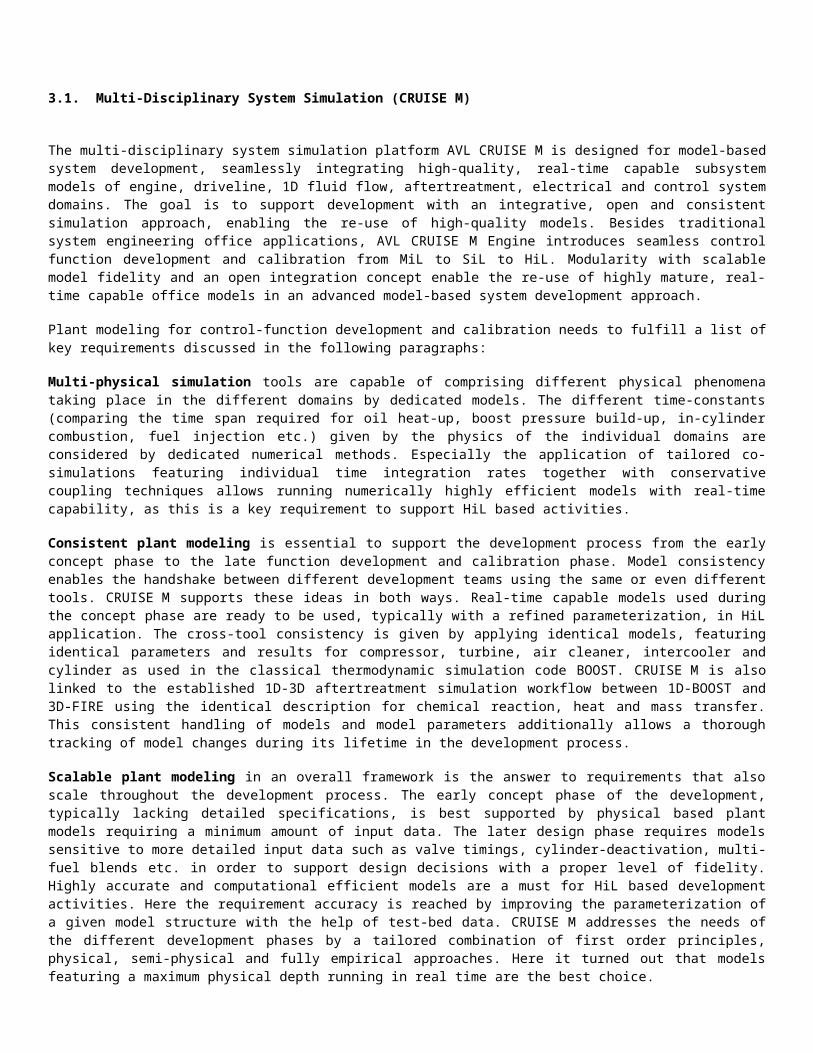
Figure 1: Schematic of the fuel path, cause and effect between models of injection, combustion and cylinder in feedback loop to the fueling control

The application of real-time capable models with higher physical depth shows great potential to address combustion control tasks in open and also in closed loop applications (see Wurzenberger and Pötsch 2). With injection timing as given input from the control unit (see Figure 1) two sub-models describing the injection system and the combustion are required. The resulting rate of heat release contributes to the in-cylinder thermodynamics leading to high pressure traces (and derived values such as peak-pressure rise, MFB50% etc.) serving as feedback to the control unit.
The real-time capable common rail injection model presented in Pötsch 3 describes the transient changes of needle lift and rail pressure including the effect of pressure waves in the injector pipe leading to transient rates of injection. The phenomenological Mixing Controlled Combustion (MCC) model presented by Chmela and Orthaber 4 is used in this study in an extended version by the Large Engine Competence Center considering a quasi-dimensional description of the Diesel spray (see Pirker et al. 5), a description of ignition delay (see Chmela et al. 6) and modeling of wall interaction. The MCC model distinguishes between two different combustion limiting regimes and superimposes both types of combustion assuming their co-existence. In Multi-Zone Combustion Model (MZCM), the injection spray is sub-divided into a high number of reaction zones which are generated during injection. Doing so, the model considers a heterogeneous distribution of temperature and air/fuel ratio in the injection spray which is seen as a prerequisite for the simultaneous simulation of NOX and soot emissions. Within each reaction zone, the main relevant physical mechanisms for the description of the combustion process are modeled: fuel/air mixing (air entrainment), evaporation and chemical reactions for heat release and pollutant formation (see Pötsch et al. 7 and 8). The Fractal Combustion Model for spark-ignited engines predicts the rate of heat release in a homogeneous cylinder charge. Knock is modeled by calculating auto-ignition in the end gas. Therefore, the model integrates the inverse of the characteristic ignition delay time as function of instantaneous temperature, pressure and species concentrations (O2 and CH4) in the unburned zone. The chemical reaction parameters for Methane auto-ignition are well documented in the literature 9.
3.4. Description of Engine and Corresponding Real-Time Engine Model
The development of the control system was done for a V16 gas engine for genset application. The engine features a central gas-admission system upstream the compressor adjusting the required air-fuel ratio. The single stage charging system with intercooler is equipped with a wastegate for load control; a throttle valve is used as an additional load-control device.
The topology of the corresponding CRUISE M real-time engine model considers the engine’s configuration and the input data (e.g. bore, stroke, valve-lift curves, turbocharger maps etc.) are in accordance with the engine specification. The model properties can be described as follows:
Physics-based approach with crank-angle resolved cylinder as well as gas path simulation considering 0D gas dynamics. Hence, pulsations of the torque of the engine and pulsations of mass flow, pressure and temperature in the gas path are simulated in real time. Although 1D wave propagation effects are not modeled, characteristics of pipe friction, pressure drop and pipe heat transfer are considered in the transfer elements by applying appropriate analytically derived approaches.
2-zone combustion model with methane knock model and simulation of pollutant formation Different possibilities of gas admission (valve controlled, Venturi system with and without variable minimum crass-
sectional area etc.) Actuators in gas path: wastegate flap and throttle valve Ignition timing as actuator to be used for sudden load control and knock control Fixed calculation step size: 1 ms (solver: Heun) Integration step size for solving system of cylinder balance equation: 1 deg. crank angle

Figure 2: Topology of the CRUISE M real-time plant model of the gas engine
4. MODEL-BASED CONTROL-SYSTEM DEVELOPMENT
The gas engine model described in the previous chapter was used as a virtual development platform to develop the ECS air path control algorithm.
4.1. Methodology and Workflow
Software development for modern engine control systems requires a defined development process and tool landscape in order to achieve high quality standards in an efficient way. The process accompanies the software development from high level requirements up to the validation of production mature embedded software. It provides the link between the different project phases and thus allows an overview and traceability of development results and decision making. If required by legislation or on customer demand, the process can be set up in compliance with established standards such as ISO, CMMI, SPICE or requirements from classification authorities.
To reduce the overhead during the development phases, the used tool chain has to be an integrated part of the process. In terms of AVL’s ECS software development approach, the applied tool landscape includes Simulink from The Mathworks and AVL CRUISE M. Simulink is customized to the specific needs of ECS software development by the use of an AVL model template and an AVL block library (AVLib). The AVL model template includes a “virtual” operating system (seeFigure 3) that assures identical overall software behavior in both Simulink and ECS hardware. The AVL block library contains usual model blocks which are highly customizable and optimized for auto-code generation.
Simulink is based on a block diagram environment for model-based design of ECS control algorithms. Its model simulation capability allows testing of the ECS algorithm behavior. Automatically generated code of the Simulink model can be implemented directly on the target ECS hardware.
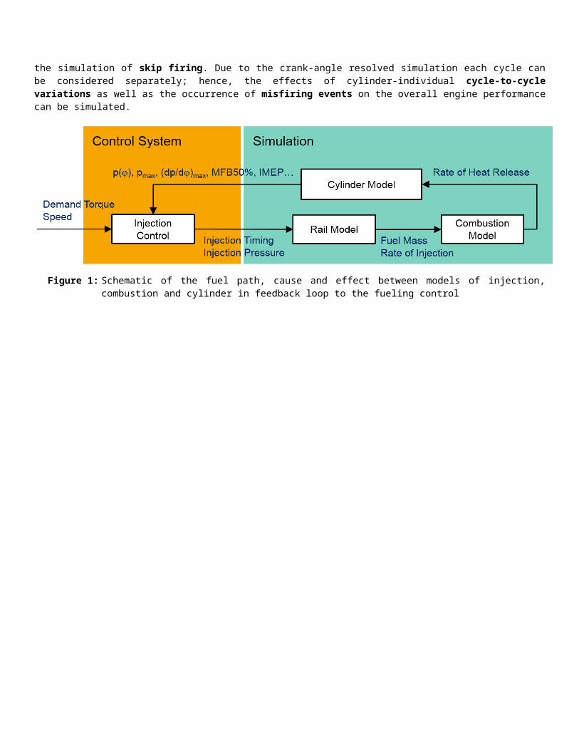
Figure 3: MiL environment
Figure 4: Interaction configurations between Simulink and CRUISE M(ECS picture by HOERBIGER)
In AVL’s ECS software development approach, Simulink and AVL CRUISE M can be coupled together to facilitate the testing of developed algorithms. Figure 4 depicts possible configurations of interaction.

In a first step as shown by the upper part of Figure 4, the ECS control functionality is developed in a MiL environment (see Figure 3). The AVL CRUISE M plant model is integrated in the Simulink environment. This interaction configuration runs on a desktop PC. Based on current engine state and operation conditions, the ECS control algorithms calculate the relevant set point values for the engine actuators such as wastegate position or opening durations of gas-admission valves. The applied AVL CRUISE M model receives the set points and simulates the behavior of actuators, engine and sensors. The ECS model reads in the sensor values and starts the calculation loop from its beginning. This simulation setup not only allows algorithm testing but also parametrization of the ECS application software in a very early development state.
In a second step, as shown by the middle part of Figure 4, the control algorithms can be implemented on the ECS hardware with auto-code generation and flash tools. The AVL CRUISE M model is moved to a real-time capable HiL simulator. This hardware setup permits a detailed investigation of the ECS behavior. Test cases can be performed in real time with real engine components to provide realistic signal I/O to the ECS. Hence, the application software made in MiL can be improved.
The AVL XIL.STATIONTM represents a further development of the classical HiL environment. The HiL test bench is expanded by an AVL PUMA system including the control panel and additional tools like AVL CAMEO. This way, the interface used by the development team at the XiL station is identical to the one used later on at the real engine. The calibration engineers can begin their work in a very early stage using the familiar working environment and at the same time, the collaboration between the different involved teams (engine development, engine control, ECS calibration etc.) is improved as they share not only the same engine model but also the same working environment.
The last step, as shown by the lower part of Figure 4, contains the integration of ECS hardware into the engine bench. Before the first engine start, tested and pre-parameterized ECS software is already available owing to the use of this development approach. Final parametrization and validation efforts are conducted at the engine bench.
The development environments MiL and HiL influence the time arrangement of the entire engine development process. Figure 5 illustrates schematically a time-based plan of an engine development. In concept phase, feasibility studies and layout simulations for ECS software functions can be performed in MiL. During prototype development phase, the MiL setup allows first parameterization of control algorithms and a HiL testing environment can be installed and operated as soon as the ECS hardware is available. Thus, before first engine start, a big part of ECS testing and parametrization work can be already performed. This reduces the effort in the product validation phase.
ConceptPrototype Development
Validation
ConceptDecision
First Engine Start
SOPProject Start
MiL
HiL
ECS Hardware Available
Engine Bench
Figure 5: Phases of engine development
A detailed description of the AVL Function & Software development process is given by Zembacher et al. 10.

4.2. Control Strategy
The engine used for this control development example is a genset application with gas engine (see Figure 6) and generator coupled by a shaft. The genset system can operate in two different modes:
Grid mode: The generator is connected to the public electrical grid and thus the speed of engine and generator is automatically kept constant to the corresponding network frequency. The load control of the engine controls the power injected to the electrical network, normally used to serve a higher level network management.
Stand-alone mode: The generator is used as stand-alone power supply for a set of electrical consumers. In this case, the load control of the engine must take care of keeping the correct engine speed and thus network frequency.
Figure 6: Engine configuration including relevant sensors (in red) and actuators (in blue)
The engine uses a central gas-admission system (Mixer) that adjusts the lambda to a desired value. The single stage turbocharger is controlled by a wastegate actuator (Wg) and the compressed mixture is cooled by a water-cooled charge-air cooler. As the gas admission is done upstream compressor, the throttle (Thr) is used as main load control actuator. The turbocharger control follows the required load in a way that not too high gas exchange losses occur created, but at the same time a certain reserve is kept to account for fast load increase requests.
Depending on the use type of gas-admission system, it is mandatory to avoid compressor surge. In order to allow a fast load decrease that needs a fast closing of the throttle valve, it is possible to open the compressor-bypass valve. If no bypass valve is available, surging can be avoided by limiting the closing speed of the throttle valve. In the following example the control strategy does not make use of a compressor-bypass valve.
In addition to the lambda control with the gas mixer and load control by the throttle valve, the ignition timing (Ign) can be used as additional actuator for engine control. Ignition can be controlled cylinder-individually allowing cylinder balancing and cylinder-individual knock control.
The main sensors used by the engine control are intake-manifold pressure (p2), boost pressure (p21), engine speed (NEng), cylinder-individual cylinder-chamber temperature (TCyl), cylinder-individual knock sensors (Knock) and generator load (Load).

4.2.1 Overall Engine Control Strategy
Figure 7: Signal flow chart of overall engine control strategy
The engine actuators and the system targets represent a multi-variable system where it is not possible to assign single targets to single actuators. The proposed control architecture (see Figure 7) was chosen in a way that different control loops can be developed and calibrated almost independent from each other by keeping the system couplings to a minimum. This extremely increases the manageability of the control system.
Depending on the chosen working mode for the genset system (grid or stand-alone mode), the engine is operated as load or as engine speed controlled. The engine speed control is needed also after engine start to bring the speed up to the required network frequency before switching into grid mode. The possibility to run in both modes is represented by a switch in Figure 7 in a simplified way.
In order to combine both working modes, the intake manifold boost pressure set point (p2_Sp) is chosen as internal load reference. As the engine speed is constant, p2_Sp defines the working point of the engine and is used to calculate the pre-control values for all actuators.
The mixer position is the most external and slowest control loop and it is used to achieve the desired average cylinder-chamber temperature. This temperature is used in operation under different environmental conditions (as gas quality), to achieve the desired trade-off between emissions and efficiency.
The air path control actuates the throttle valve and the wastegate to achieve the correct intake manifold pressure that corresponds to the desired load and a load reserve. As both actuators are strongly coupled, it is not possible to apply separate independent control loops. It is necessary to apply a central and multi-variable control approach to take into account the interactions between the actuators. The detailed presentation of the used multi-variable air path control strategy is the main focus of the next chapter.
As the gas-admission system and the air path actuators cannot account for very fast load changes, they are compensated by temporary corrections of the ignition timing (see Transient Load Control block in Figure 7). The air path control passes the ignition control information about the non-achieved pressure. Out of this pressure deviation, the ignition control calculates the related torque deviation and the needed ignition timing correction for the current working point to achieve the desired torque or load. As the air path control will always be capable to achieve the targets after the dynamic transition, the ignition correction is only needed for a limited transient time period and is not critical in terms of component protection. As the ignition correction shortly produces a shift of the average ignition timing, it is necessary to freeze the cylinder temperature control with the gas mixer to avoid an additional lambda reaction that would be too slow anyhow. For

the presented results this transient ignition timing correction is not used and the average ignition timing can be considered as constant.
The ignition timing is additionally used for cylinder temperature balancing. As previously mentioned, the average cylinder temperature across the cylinders is controlled with lambda, but the cylinder individual temperature deviations from the average are compensated with cylinder individual ignition timing corrections. These corrections are applied in a way that they don’t affect the average ignition timing or the average cylinder temperature across the cylinders.
One last usage of the ignition timing is cylinder individual knock compensation. This correction has always higher priority than the remaining ignition related corrections.
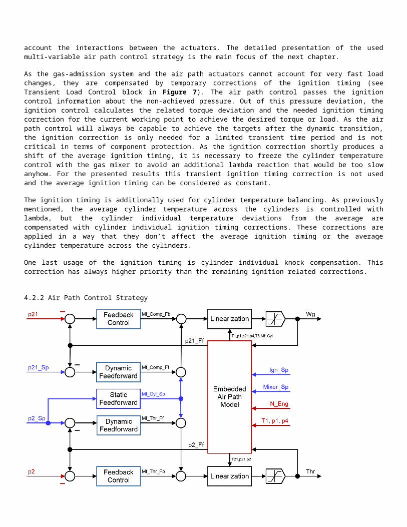
4.2.2 Air Path Control Strategy
Figure 8: Signal flow chart of air path control strategy
Figure 8 shows the signal flow chart of the air path control block from Figure 7. The combined actuation of throttle valve and wastegate has the target to control the pressures p2 and p21 to their target values p2_Sp and p21_Sp. The prioritization is chosen in a way that the throttle valve is used exclusively for the p2 control and except for the case of compressor surge, it does not take the p21 control deviation into consideration. However, the behavior of the p2 control loop will be indeed influenced by the other actuator (wastegate). As the influence of wastegate on p2 are known through an embedded system model, they can be compensated by the linearization of the p2 actuator. This means that if p21 does not behave as expected, the position of the throttle valve is compensated to achieve the same mass flow into the intake manifold. This way, the coupling from p2 to p21 can be compensated.
The other way around, the disturbance created by the p2 control to the p21 control is intentionally not compensated because the pressure reserve is foreseen to make sure, that the mixture volume stored in the boost volume can be used as buffer in the short term to control the load with the smaller intake-manifold volume. The p21 control loop is by nature much slower (otherwise the throttle valve would not be necessary), so that it is not destabilized by p2 disturbances.
As previously explained, the linearization blocks (right side of Figure 8) take care of decoupling both control loops. Additionally they have the advantage that the controllers (left side of Figure 8) see plants with an approximately linear behavior. This significantly simplifies the development and calibration of the controllers. The chosen intermediate physical variables (between controller and linearization) are the desired mass flows over compressor (Mf_Comp_..) and throttle

valve (Mf_Thr_..). In case the linearization performs perfectly, the internal mass flows correspond exactly to the real ones, otherwise there will be deviations between internal and real mass flows and the behavior of the control system will be only nearly linear from the controller viewpoint. Since the controllers present a certain robustness against modelling errors, this approximately linear behavior is still adequate.
Thus, for both control loops the internal actuator value is the corresponding mass flow. These mass flows are calculated out of three additive terms: a static and a dynamic feedforward term, which represent together the overall feedforward term (Mf_..._Ff) and a feedback control term (Mf_..._Fb).
The static feedforward term does now show any own dynamics and represents the needed mass flows for the requested set points in stationary conditions. Since the gas is admitted upstream the compressor, in steady state conditions all mass flows in the system are identical and correspond to the mass flow into the cylinders (Mf_Cyl_Sp). In case of a perfect static feedforward control the resulting pressures would match exactly the set points after the transient period.
The dynamic feedforward term does also not make use of the measured pressures and has the target to accelerate the transient response which is performed by letting the dynamic feedforward controller control the embedded plant model to the set point and then sending the resulting actuator value to the real system.
The behavior achieved with the internal control loop represents the best achievable behavior, assumed the internal plant model fits perfectly the real system. For this case it is not desirable to have a correction from the feedback controller as it would only deteriorate the result. To achieve this the feedback controller does not use the external set point but the expected pressure from the embedded plant model resulting from the actuation of both feedforward terms. This means that in case of a perfect fit between embedded plant model and real system, the feedback controller would always see zero control error. This ideal case will normally not appear and there will always be deviations between embedded plant model and real system. The feedback controller just controls the real system to the embedded model and not to the external original set point that he could not reach anyhow.
Those three terms are used for both actuators in the same way, whereat the static feedforward corresponds to the desired cylinder mass flow (Mf_Cyl_Sp) for both of them.
The described configuration coordinates the interventions from feedforward and feedback parts. It ensures that there will be no double interventions and that the calibration of each term can be done independently (a recalibration of one term does not imply a recalibration of the other ones). Due to this configuration each part can be developed and tested separately by deactivating the other parts. Additionally, once each of the terms works in an optimal way separately, the complete control structure will perform best.
An additional special situation is also considered in case the intended actuation of the throttle valve would lead to compressor surge. In this case the priority of the throttle valve is inverted and it is not used to control p2, instead of keeping p21 just below the surge limit calculated by the embedded plant model. In this transient situation, the control accepts a too high p2 pressure until the turbocharger speed has dropped to a safe level. The typical situation where this happens is the request for a fast load reduction (e.g. emergency shut down from public grid) where the turbocharger speed is driven along the surge limit (with a defined safety margin).

Figure 9: Signal flow chart of embedded air path model

Figure 9 shows the signal flow chart of the embedded air path model block from Figure 8. The embedded plant model is built out of own library components with predefined interfaces. The library components are designed to run in an ECS microcontroller with lowest possible resource consumption. The embedded model was calibrated to behave as close as possible to the CRUISE M model that was used as external plant model.
The gas states (red lines Gst) are represented by a bus signal containing pressure, temperature and mass fractions of the considered gas species. In the current example, the gas species air, inert gas (gas burned with lambda = 1) and unburned fuel gas are considered. The gas properties of the resulting species mixture is calculated automatically out of the gas properties of the single species. As additional interface, a gas flow signal bus is used (orange lines Gfl), containing enthalpy flow and a vector with the mass flows of the gas species. The gas state signal bus represents intensive signals that can be measured directly and the gas flow signal bus represents extensive signals that can be integrated. This implies that all the mass flows entering or leaving a volume can be added outside of the volume blocks and as a result a single library block can be used to model all relevant volumes in the system.
The chosen block icons represent energy exchanges (crosses in two or three colors) or energy storage (abstract depot symbol). The red color represents the internal gas energy, the yellow one the thermal coolant energy and the blue one the mechanical or kinetic energy of a rotating component (turbocharger, crankshaft). The brighter tone of each of the colors represents the extensive value, while the darker ones are intensive signals.
In order to easily extract single signals out of the busses, the library includes specific blocks (smaller blocks without icon) that can be considered as virtual sensors.
4.3. Results
The following simulation results show the performance of the air path control algorithm in a MiL environment using the previously described CRUISE M engine model.
Figure 10: Simulation in grid mode with independent p2_Sp and p21_Sp steps
0 5 10 15 20 25 30Time [s]
Pre
ssur
es [b
ar]
1.50
1.53
1.56
1.591.62
1.65
1.68
1.71
Act
uato
rs [%
]
0
20
40
60
80100
Load
[Nm
]
3600
3800
4000
4200
p21Spp21p2Spp2ThrWgMEng
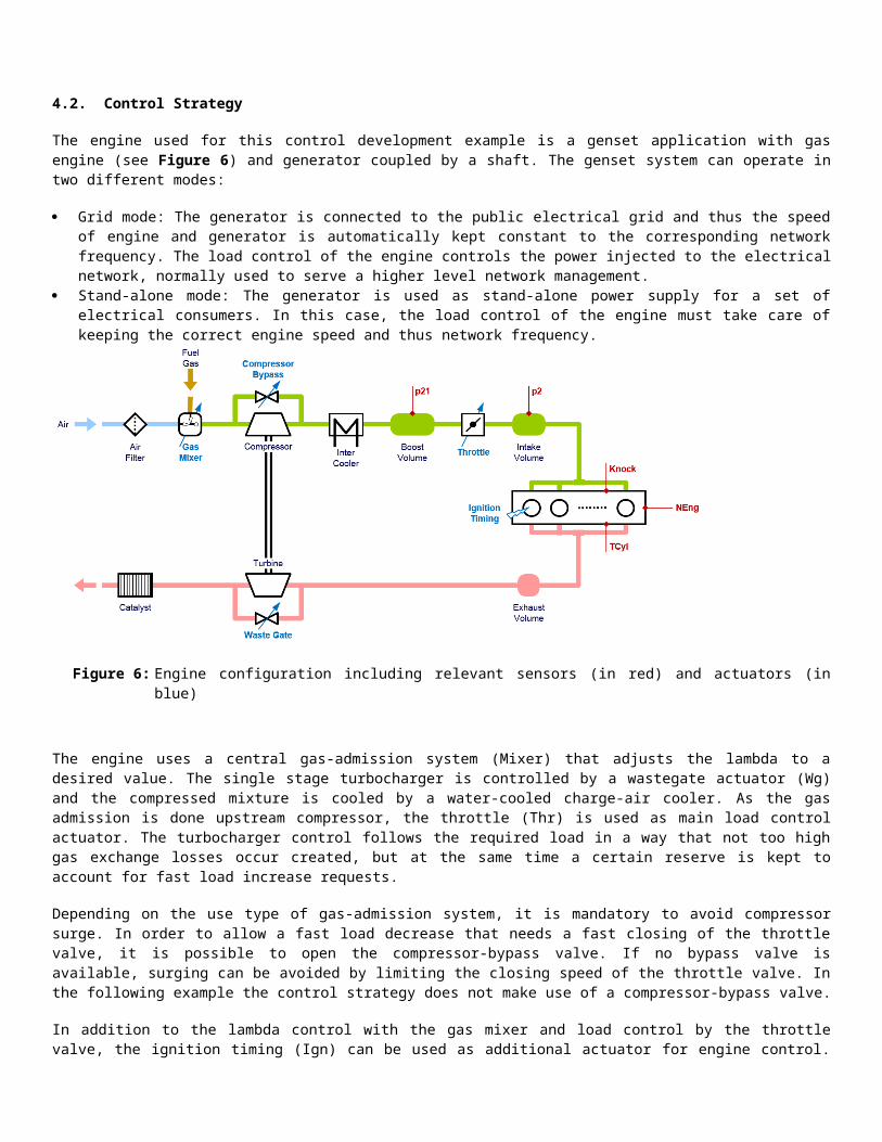
Figure 10 shows a simulation in grid mode. The air path set points were manipulated independently to show the coordinated and independent control of intake manifold pressure (p2) and boost pressure (p21). In the first half time sequence, p2_Sp upwards and downwards steps are performed with a small pressure reserve, followed by a set point step of the pressure reserve. ). In the second half time sequence the steps of the first are repeated with the higher pressure reserve.
The upwards p21_Sp step at simulation time 10 s show the good working decoupling of the p2 control loop to disturbances coming from the p21 control loop. The deviations on p21 after every p2_Sp step are intended as they imply the pressure reserve being emptied out or filled up. The different p2 dynamic behavior at simulation times 5 s and 20 s clearly show, that a bigger pressure reserve allows a much faster p2 pressure build-up.
Figure 11: Simulation in grid mode with stepwise generator load increase and decrease
Figure 11 depicts a simulation in grid mode with a typical situation: The generator load is increased stepwise up to 100% and decreased again. As all air path set points are a function of the desired load via p2_Sp, they all change simultaneously. The simulation results show that also in this case the coupled system can be controlled in a stable way without relevant overshoots at any load level.
Figure 12 shows a simulation in grid mode with a large generator load increase and decrease. In this situation it is mandatory to fully use the actuators range, which presumes an effective anti-windup mechanism. The applied anti-windup allows an immediate use of the full actuator range (for the case of load increase: throttle fully open and wastegate fully closed), whereby these limits are left afterwards just in time to avoid unwanted over-/undershoots in the pressures. While the actuators are limited, the control performance cannot be further improved. The actuator saturation is considered in the embedded model allowing the calculation of the system behavior in these situations too.
The second part of the simulation shows a large load generator decrease. In this case the anti-surge mechanism allows an immediate closing of the throttle valve and limits the maximum allowed p2 to drive down the turbocharger speed along the surge limit. Without this mechanism, the controller would just immediately closed the throttle valve leading to the mentioned unwanted compressor surge behavior.
0 10 20 30 40 50 60 70 80 90 100 110 120 130 140 150Time [s]
Pre
ssur
es [b
ar]
1.0
1.5
2.0
2.5
3.0
3.5
4.0
Act
uato
rs [%
]
0
20
40
60
80
100
Load
[Nm
]
2500
5000
7500
10000
p21Spp21p2Spp2ThrWgMEng

Figure 13 shows a simulation in stand-alone mode (engine speed is closed loop controlled by ECS) with two generator load steps from 80% to 90% and 90% to 100%. The engine speed controller keeps the engine speed constant to the corresponding network frequency. As the load changes are external to the genset system and occur without any previous notice, it is not possible to apply a disturbance attenuation feedforward control to achieve a perfect constant speed. The
controller detects the load increase only through the speed drop and is therefore not able to react sooner. Nevertheless it is possible to reduce the engine speed deviations to a minimum by a properly coordinated cascaded control structure.
Figure 12: Simulation in grid mode with large generator load increase and decrease steps
Figure 13: Simulation in stand-alone mode with generator load increase steps
0 5 10 15 20 25 30 35Time [s]
Pre
ssur
es [b
ar]
1.0
1.5
2.0
2.5
3.0
3.5
4.0
Act
uato
rs [%
]
0
20
40
60
80
100
Load
[Nm
]
2500
5000
7500
10000
p21Spp21p2Spp2ThrWgMEng
0 5 10 15 20 25 30Time [s]
Pre
ssur
es [b
ar]
1.70
1.85
2.00
2.15
2.30
2.45
2.60
Act
uato
rs [%
]
0
20
40
60
80
100
Load
[Nm
]
4500
5000
5500
6000
Spe
ed [r
pm]
1460
1480
1500
1520
p21Spp21p2Spp2ThrWgMEngMGenSpeed

5. SYSTEM SIMULATION FOR LARGE ENGINE APPLICATIONS
Whereas the control system development described above needs only to consider detailed models of mainly two subsystems (controls and engine), further plant models can be used for the purpose of extended system simulation. The integrated simulation approach is a further use case for physics-based real-time engine models as part of overall systems. The multi-domain system simulation of mining trucks, locomotives or ship systems allows the optimization of the energy management and the investigations on the interactions between various subsystems (engine – transmission/propulsion – consumers – aftertreatment – waste heat recovery system – hybrid elements – energy storage – operator/driver assistance systems – communication systems – control systems etc.). The prediction of performance, consumption of resources and emissions is related to the real-life operation and the system simulation facilitates the optimization of operating strategies in view of best performance both in terms of economy and environmental impact. Beginning with a fully virtual simulation environment in the concept phase, subsystems are successively replaced by hardware components in the course of the development enabling tests under real-life conditions. The merging of simulation and testing world on XiL systems supports the development of large engine applications in an effective and efficient manner. The setup of virtual test beds as well as simulators for large engine applications for the purpose of training of engineers and education of students can be seen as an additional application field of system simulation using advanced plant models.
6. CONCLUSION AND OUTLOOK
Especially for large engines model-based development approaches are promising and attractive as the availability of prototype engines and components is limited and as the effort for operating a multi-cylinder engine on a test bed is high and cost intensive. Using the example of control-system development there are many tasks with successful application of the virtual environment, such as function and algorithm development, software generation and ECS integration, testing and validation in MiL and HiL environment and calibration. Innovative real-time capable engine models with highest modeling depth, even simulating the discontinuous engine’s processes in crank-angle resolution, increase the value of the model-based approach significantly. By increasing the processor performance of computers the usage of advanced 1D thermodynamic cycle simulation models for model-based development could be standard in the future.
By combining and enhancing already established capabilities, simulation models, data storage or automation systems and execution environments, early, open and consistent functional integration is made possible to master complexity and speed. The model based development approach involves many simulation tools, departments and development environments. With the Integrated Open Development Platform (IODP), a strategic orientation of AVL, the already existing and established capabilities, simulation models, data storage systems, execution/testing environments or automation systems are combined and enhanced. Thus, new development environments are created.
REFERENCES
1. Strasser R., Wurzenberger J. C. and Roduner C. A., “Innovative physikalische Echtzeitmotormodelle: Durchgängige ECU-Entwicklung und Kalibration von der Projektidee bis hin zum Produktionsbeginn“, VPC, 15. MTZ-Fachtagung, 2013
2. Wurzenberger J.C. and Pötsch C., “Plant Modeling for Closed Loop Combustion Control – A Thermodynamic Consistent and Real-Time Capable Approach”, SAE Technical Paper 2015-01-1247, 2015
3. Pötsch C., “Crank-angle resolved modeling of fuel injection and mixing controlled combustion for real-time application in steady-state and transient operation”, SAE Technical Paper 2014-01-1095, 2014
4. Chmela F. G. and Orthaber G. C., “Rate of Heat Release Prediction for Direct Injection Diesel Engines Based on Purely Mixing Controlled Combustion”, SAE Technical Paper 1999-01-0186, 1999
5. Pirker G., Chmela F. and Wimmer A., “ROHR Simulation for DI Diesel Engines Based on Sequential Combustion Mechanisms”, SAE Technical Paper 2006-01-0654, 2006
6. Chmela F., Engelmayer M., Pirker G. and Wimmer A., “Prediction of turbulence controlled combustion in diesel engines”, THIESEL, Conference on Thermo- and Fluid Dynamics Processes in Diesel Engines, 2004
7. Poetsch, C., Ofner, H. and Schutting, E., “Assessment of a Multi Zone Combustion Model for Analysis and Prediction of CI Engine Combustion and Emissions”, SAE Technical Paper, doi:10.4271/2011-01-1439
8. Poetsch, C., Ofner, H. and Cartellieri, W., “Analysis of Thermodynamic Characteristics of Diesel Engine Emission Control Strategies Using a Multi-Zone Combustion Model“, SAE Int. Journal of Engines 5(3):2012, doi: 10.4271/2012-01-1340
9. T Huang, J.: “Natural gas combustion under engine-relevant conditions.”, PhD Thesis, University of British Columbia, 2006
10. G. Zembacher, C. Roduner, D. Valero, A.Höpfner, A. Przymusinski, “Efficient Software Development Applying a Model-Based Concept.”, Symposium on International Automotive Technology (SIAT) 9.-12.1.2013, Paper 2013-26-0087, India, 2013.