paper id d02 design and manufacturing of corn … · 2019-01-03 · as gears, pulleys, flywheels,...
TRANSCRIPT

NOVATEUR PUBLICATIONS International Journal of Innovations in Engineering Research and Technology [IJIERT], ISSN: 2394-3696
Conference Proceedings of i - Mechanical Engineering Students Conference 2018 (i – MESCON 18) 28th December, 2018
117 | P a g e
PAPER ID –D02 DESIGN AND MANUFACTURING OF CORN SHELLING MACHINE
Hrishikesh H. Pande
Student, BE Mechanical Engineering ICEM, Pune, INDIA
[email protected] Nikhil Raj
Student, BE Mechanical Engineering ICEM, Pune, INDIA
Jayendra J. Raut
Student, BE Mechanical Engineering ICEM, Pune, INDIA
Abhishek V. Taral
Student, BE Mechanical Engineering ICEM, Pune, INDIA
S. S. Shirbhate
Asst. Prof. Mechanical Engineering Department, ICEM, Pune, INDIA [email protected]
Abstract— India depends on agriculture to drive the engine of its
economic development. Corn has been cast in the lead role of this
ongoing storyline of agriculture success, and without corn, the
India farm sector would be just a shell of what is has now
become. Corn is grown on small scale, corn’s price is growing day
by day it has almost became the double of the price of the maize.
Corn Sheller is a major problem of corn production, especially in
India. The performance of the machine will be evaluated in terms
of shelling efficiency, material efficiency, etc. The project
describes about the design of various components of corn shelling
machine. Overall, this project involves process like design,
fabrication and assembling of different components, etc. This
project describes the design and development of motorized corn
shelling machine.
Keywords— Corn, Shelling, Hopper, Shutter, Threshing
chamber, collector, wastage, drum
I. INTRODUCTION
In today’s industrial world man’s innovative ideas has taken
him towards all directions concerning about the production
and safety in industrial establishments. Some instruments are
of shear excellence where as others are the result of long
research and persistent work, but it is not the amount of time
and money spends in the invention of device or the
sophistication of it operation is important, but its convenience,
utility and operational efficiency that are important in
considering the device.
De-seeding of corn is the process of removal of its
inner layers, leaving only the cob or seed rack of the corn .De-
seeding is the process of removing the hulls (or chaff) from beans and other seeds.
The existing methods of corn de-husking in agriculture
industry consist of breaking the grains by hand or by using
large machinery for deseeding. Both of which are not effective
for a developing economy like India where farmers have little money for investment.
II. LITERATURE REVIEW
There are three different types of De-seeding systems
that can be used to process soybeans: Hot De-seeding, Warm
De-seeding and Cold De-seeding. Hot De-seeding is the
system offered in areas where beans are processed directly
from the field. Warm De-seeding is often used by processors
who import their soybeans. Cold De-seeding is offered to
plants that have existing drying and conditioning equipment,
but need to add De-seeding equipment to produce high protein
meal. The different De-seeding temperature options are for
different types of production, beans and preparation
equipment.
Anant J. Ghadi and Arunkumar (august 2014, Belgaum)- The
existing methods of corn de-husking in agriculture industry consist of breaking the grains by hand or by using large
machinery for deseeding, both of which are not effective for a
developing economy like India where farmers have little
money for investment.
Oriaku E.C, Agulanna C.N, Nwannewuihe H.U, Onwukwe
M.CAnd Adiele (2014, Enugu)- Explained that, corn the
American Indian word for corn, and means literally that which
sustains life. It is, after wheat and rice, the most important
cereal grain in the world, providing nutrients for humans and
animals and serving as a basic raw material for the production
of starch, oil and protein, alcoholic beverages, food sweeteners
and, more recently, fuel and explained that One of the most important processing operations done to bring out the quality
of maize is shelling or threshing of maize.
III. DESIGN AND CALCULATIONS
Parts-
The device is simple in operation consisting of following
parts:
a) Stand
b) Motor
c) Screener
d) Main head
e) Belt
f) Shaft
g) Pulleys
Calculations-
1. Design of shaft-
The corn load and Welded iron road weight = 25 kg = 250N

NOVATEUR PUBLICATIONS International Journal of Innovations in Engineering Research and Technology [IJIERT], ISSN: 2394-3696
Conference Proceedings of i - Mechanical Engineering Students Conference 2018 (i – MESCON 18) 28th December, 2018
118 | P a g e
The screwed dimension or diametric radius = 100mm
Fig 3.1 Screwed shaft
Total torque on crank = 250 x 50 = 12500N-mm
P = 2𝜋𝑁𝑇
60
Speed required in the range 150 to 300rpm
P = 392 watt
So we have selected 0.5hp motor.
Motor power = 5 watt
Motor speed = 1440 rpm
Motor supply 230 V single phase
T = Max Torque generated to rotating Crank
Ϭ = 145 N/ mm2 considering factor of safety = 4
As per Design data book shaft material is selected
Carbon steel C40
C40= Sut= 580 N/mm2
Yield= 435 N/mm2
σ = 145 N/mm2
As per ASME code
0.3 X Yield strength N/mm2
0.18 X ultimate strength N/mm2} whichever is smaller
0.3 x 330 = 99 N/mm2 .....(a)
0.18 x 580 = 104 N/mm2 .....(b)
From equation (a) & (b)
Allowable stress value will be 99 N/mm2
If key ways will provide to shaft then
τ = 99 x 0.75 = 74.25 N/mm2
WE know that,
𝑇 =𝜋
16𝑑3𝜏
Where T = 12500N-mm
By using above equation drive shaft diameter
d = 9.33mm …..(c)
Fig 3.2 Drive shaft loading condition
P = 1000 N
∑𝐹𝑌 = 0
RA = 1000
Calculation of bending moment at loading point P,
BM at M = 1000 x 50 = 50000N-mm
We know,
𝑀 =𝜋
32𝑑3𝜎
Ϭ = 145 N/ mm2 considering factor of safety = 4
By using above equation drive shaft diameter
d = 15.49mm …..(d)
From equation c and d we have selected the diameter of shaft
= 20mm considering extra jerk and for safe design.
According to maximum shear stress theory
Equivalent torque
𝑇𝑒 = √(𝐾𝑏𝑀𝐴)2 + (𝐾𝑡𝑇)
2
For design data book
Equivalent bending moment
NOVATEUR PUBLICATIONS International Journal of Innovations in Engineering Research and Technology [IJIERT], ISSN: 2394-3696
Conference Proceedings of i - Mechanical Engineering Students Conference 2018 (i – MESCON 18) 28th December, 2018
119 | P a g e
𝑀𝑒 =1
2[𝑀 +√(𝐾𝑏𝑀𝐴)
2 + (𝐾𝑡𝑇)2]
Te = 116297 N-mm
Me = 83148 N-mm
We know,
𝑇𝑒 =𝜋
16𝑑3𝜏
𝑀 =𝜋
32𝑑3𝜎
N/mm2 and 74 > 73 = ځ
Ϭ = 105 < 145 N/mm2
By using above equation we have checked the allowable shear
stress and allowable bending stress and it is seen that the both
values are within limit hence design is safe.
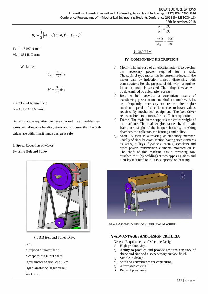
2. Speed Reduction of Motor-
By using Belt and Pulley,
Fig 3.3 Belt and Pulley Drive
Let,
N1=speed of motor shaft
N2= speed of Output shaft
D1=diameter of smaller pulley
D2= diameter of larger pulley
We know,
𝑁1𝑁2
=𝐷2𝐷1
1440
𝑁2=200
50
N2=360 RPM
IV- COMPONENT DISCRIPTION
a) Motor- The purpose of an electric motor is to develop
the necessary power required for a task.
The squirrel type motor has its current induced in the
motor bars by induction thereby dispensing with
commutators. For the purpose of this work, a squirrel
induction motor is selected. The rating however will
be determined by calculation results.
b) Belt- A belt provides a convenient means of
transferring power from one shaft to another. Belts are frequently necessary to reduce the higher
rotational speeds of electric motors to lower values
required by mechanical equipment. The belt driver
relies on frictional effects for its efficient operation.
c) Frame- The main frame supports the entire weight of
the machine. The total weights carried by the main
frame are weight of the hopper, housing, threshing
chamber, the collector, the bearings and pulley.
d) Shaft- A shaft is a rotating or stationary member,
usually of circular cross-section having such elements
as gears, pulleys, flywheels, cranks, sprockets and
other power transmission elements mounted on it. The shaft of this machine has a threshing tool
attached to it (by welding) at two opposing sides and
a pulley mounted on it. It is supported on bearings.
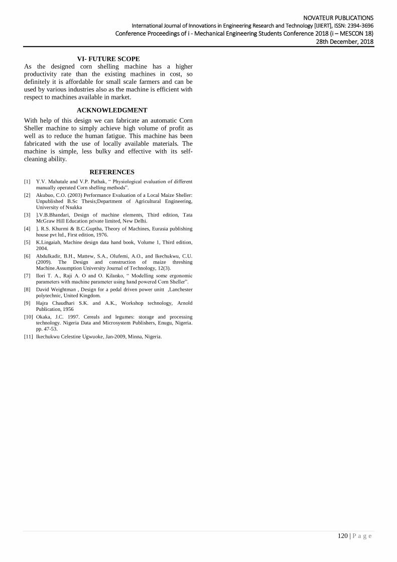
FIG 4.1 ASSEMBLY OF CORN SHELLING MACHINE
V-ADVANTAGES AND DESIGN CRITERIA
General Requirements of Machine Design
a) High productivity.
b) Ability to produce and provide required accuracy of
shape and size and also necessary surface finish.
c) Simple in design.
d) Safe and convenience for controlling.
e) Affordable costing.
f) Better Appearance.
NOVATEUR PUBLICATIONS International Journal of Innovations in Engineering Research and Technology [IJIERT], ISSN: 2394-3696
Conference Proceedings of i - Mechanical Engineering Students Conference 2018 (i – MESCON 18) 28th December, 2018
120 | P a g e
VI- FUTURE SCOPE
As the designed corn shelling machine has a higher productivity rate than the existing machines in cost, so
definitely it is affordable for small scale farmers and can be
used by various industries also as the machine is efficient with
respect to machines available in market.
ACKNOWLEDGMENT
With help of this design we can fabricate an automatic Corn
Sheller machine to simply achieve high volume of profit as
well as to reduce the human fatigue. This machine has been
fabricated with the use of locally available materials. The
machine is simple, less bulky and effective with its self-
cleaning ability.
REFERENCES
[1] Y.V. Mahatale and V.P. Pathak, “ Physiological evaluation of different
manually operated Corn shelling methods”.
[2] Akubuo, C.O. (2003) Performance Evaluation of a Local Maize Sheller:
Unpublished B.Sc Thesis;Department of Agricultural Engineering,
University of Nsukka
[3] ].V.B.Bhandari, Design of machine elements, Third edition, Tata
McGraw Hill Education private limited, New Delhi.
[4] ]. R.S. Khurmi & B.C.Guptha, Theory of Machines, Eurasia publishing
house pvt ltd., First edition, 1976.
[5] K.Lingaiah, Machine design data hand book, Volume 1, Third edition,
2004.
[6] Abdulkadir, B.H., Mattew, S.A., Olufemi, A.O., and Ikechukwu, C.U. (2009). The Design and construction of maize threshing
Machine.Assumption University Journal of Technology, 12(3).
[7] Ilori T. A., Raji A. O and O. Kilanko, “ Modelling some ergonomic
parameters with machine parameter using hand powered Corn Sheller”.
[8] David Weightman , Design for a pedal driven power unitt ,Lanchester
polytechnic, United Kingdom.
[9] Hajra Chaudhari S.K. and A.K., Workshop technology, Arnold
Publication, 1956
[10] Okaka, J.C. 1997. Cereals and legumes: storage and processing technology. Nigeria Data and Microsystem Publishers, Enugu, Nigeria.
pp. 47-53.
[11] Ikechukwu Celestine Ugwuoke, Jan-2009, Minna, Nigeria.