paper folding machine - morgana€¦ · issue 8 march 2008 90-103 paper folding machine morgana...
TRANSCRIPT

ISSUE 8 March 2008
90-103
PAPER FOLDING MACHINE
Morgana Systems Limited United Kingdom
Telephone: ( 01908 ) 608888 Facsimile: ( 01908 ) 692399
OPERATORS MANUAL
MajorMajor
Website: www.morgana.co.uk
SERIAL No. 901376KKAF ONWARDS
Page 2 PAPER
INDEX
INTRODUCTION & SPECIFICATION
PAGE 4
SAFETY Do’s & Don’ts 5
THE ‘MAJOR’
6
The Morgana ‘Major’
Labeled Photograph
Side Lay
QUICK START CHART (METRIC) 8
QUICK START CHART (IMPERIAL) 9
QUICK START GUIDE 10
MORGANA ‘MAJOR’ OPERATOR INSTRUCTIONS
111111111111121212121314141414141414141415
16/1718191920
Paper GateSuction OpeningSetting the ‘Short Suck’ or ‘Long Suck’ mode of operationSetting the Vacuum BleedSetting the SpeedAir Distribution Knob (D)Air Separation Knob (E)Back Stop (F)Fold PlatesRoller TiltDeflectStacking RollerEmergency Stop Switch (S)Main Switch (T)Feed Switch (U)Batch Knob (V)Reset Switch (W)OverlapSpeed Control (R)Plug-in PerforatorFitting Perforator BladesSetting PerforatorsScoringIllustration of Plug-in PerforatorFolding Card
INDEX
Page 3FOLDER
Major
MORGANA ‘MAJOR’ OPERATOR INSTRUCTIONS (CONTINUED)
212222
FOLDING TIPS & TROUBLE SHOOTING
23232324242424252525
DISPATCH KIT 26
ACCESSORIES & OPTIONS 27
RECOMMENDED SPARES 28
Roller AdjustmentSensor CleaningFolding Plates - Maintenance
Double Sheet FeedingFold is not Square or ConsistentPaper will not Stack ConsistentlyPaper will not Deflect when using One Fold or PerforatingTotal and Batch Counter not WorkingO-Lap Keeps appearing on Counter BoardNo Power to MachineMain Switch Cuts OutFold Roller Replacement
Sheets Difficult to Feed

Page 4 PAPER
INTRODUCTION AND SPECIFICATIONMajor is a registered trade mark of Morgana Systems Ltd. The Morgana Major is designedto be used in today’s environment of document production, the Morgana Major can beused by non skilled personnel by following this easy to use operators guide. There are veryfew operator adjustments required on the machine and our section will getyou started very quickly, but we do recommend that you take a little time to read thismanual, to ensure that you fully understand the machine. We have also included a
section. Be sure to read this section calling a serviceengineer to avoid unnecessary expense. A maximum paper weight cannot be specified, asthis can be governed by the hardness of the substrate or the type of fold required to beproduced.
Feeding System .......................................... Bottom suction feedMax. Sheet Size .......................................... 674mm Long x 365mm Wide (26.5” x 14.37”)Min. Sheet Size ........................................... 160mm Long x 140mm Wide (6.3” x 5.5”)Max. Paper Weight ...................................... 240gsm Max. according to hardness, type
of fold, grain direction and substrateMin. Paper Weight ....................................... 56gsmMax. No. Folds per Sheet............................. 2
Speed per Hour (A4 Material) ...................... 27,500 sheets (Stream Feed)
QUICK START
TIPS &TROUBLE SHOOTING before
IMPORTANT
Note:
the operating environment should be controlled to a temperature between
16° C and 27° C Maximum.
Max. Fold Length ......................................... 337mm (13.25”)
17,250 sheets (Pulsed Feed)
Speed per Hour (A3 Material) ...................... 18,000 sheets (Stream Feed)13,250 sheets (Pulsed Feed)
Dimensions .................................................. L: 1168mm H: 990mm W: 493mmWeight ..........................................................120Kgs (+11Kgs packing)Power Requirement ......................................1 phase 220 / 240v
Specification
The production speed varies according to the material size.
Major
Major
Page 5FOLDER
Safety Do’s & Don’ts
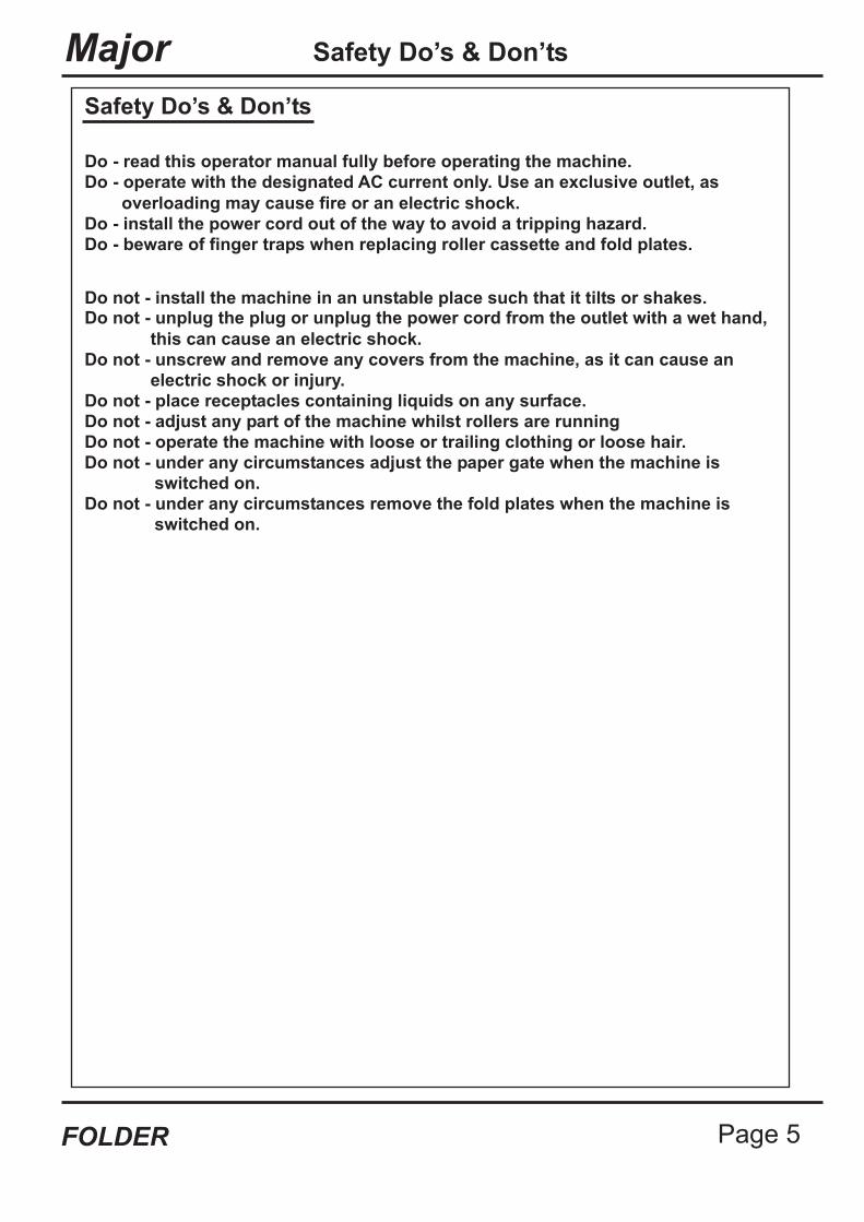
Safety Do’s & Don’ts
Do - operate with the designated AC current only. Use an exclusive outlet, as
overloading may cause fire or an electric shock.
Do - install the power cord out of the way to avoid a tripping hazard.
Do - beware of finger traps when replacing roller cassette and fold plates.
Do not - install the machine in an unstable place such that it tilts or shakes.Do not - unplug the plug or unplug the power cord from the outlet with a wet hand,
this can cause an electric shock.
Do not - unscrew and remove any covers from the machine, as it can cause an
electric shock or injury.
Do - read this operator manual fully before operating the machine.
Do not - place receptacles containing liquids on any surface.
Do not - adjust any part of the machine whilst rollers are running
Do not - operate the machine with loose or trailing clothing or loose hair.
Do not - under any circumstances remove the fold plates when the machine is
Do not - under any circumstances adjust the paper gate when the machine is
switched on.
switched on.
Page 6 PAPER
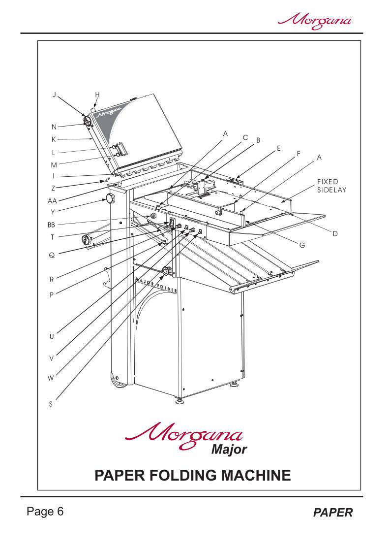
PAPER FOLDING MACHINE
Major
Z
HJ
Y
N
K
L
M
I
AA
R
Q
T
U
V
W
S
P
A
BC
EF
G
A
F IXE D
S IDE LAY
D
BB

Page 7FOLDER
Major
BLANK
PAGE
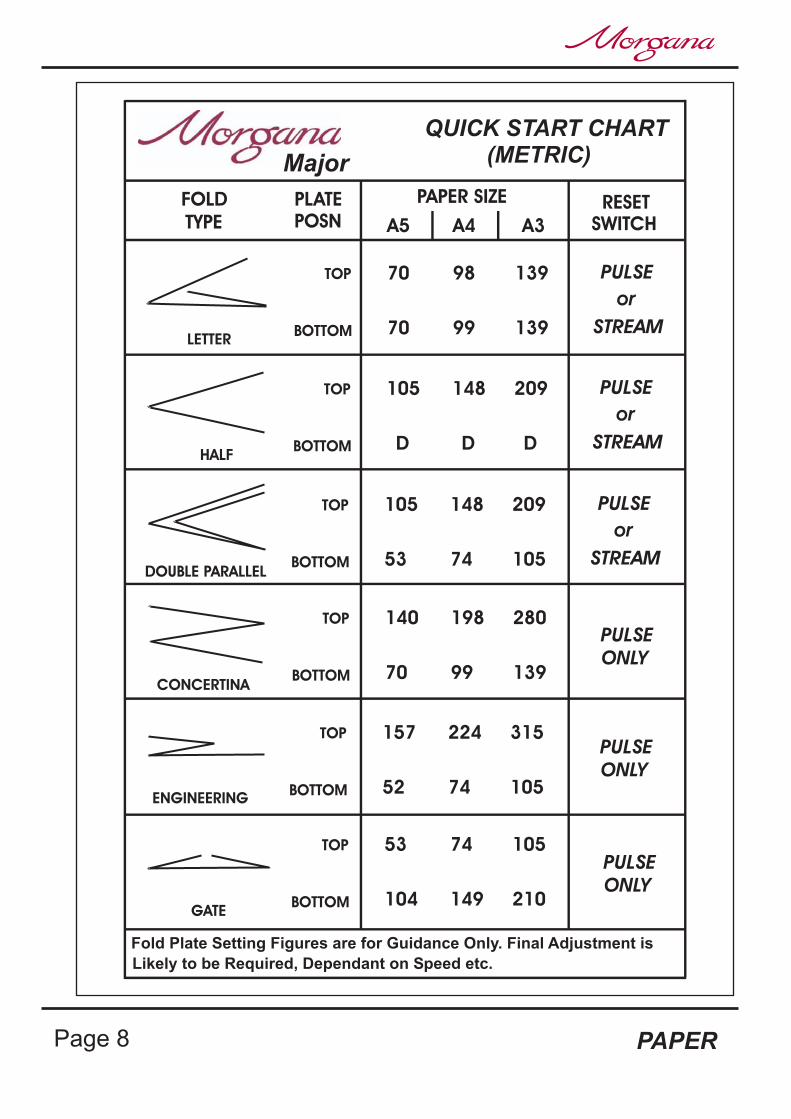
QUICK START CHART(METRIC)
FOLD
LETTER
TYPE
PLATE
POSN
TOP
BOTTOM
PAPER SIZE
A5 A4 A3
70 98 139
70 99 139
RESET
SWITCH
PULSE
STREAM
or
HALF
TOP
BOTTOM
105 148 209
D D D
PULSE
STREAM
or
DOUBLE PARALLEL
TOP
BOTTOM
105 148 209
53 74 105
PULSE
STREAM
or
CONCERTINA
TOP
BOTTOM
140 198 280
70 99 139
PULSE
ONLY
ENGINEERING
TOP
BOTTOM
157 224 315
52 74 105
GATE
TOP
BOTTOM
53 74 105
104 149 210
PULSE
ONLY
PULSE
ONLY
Major
Fold Plate Setting Figures are for Guidance Only. Final Adjustment is
Likely to be Required, Dependant on Speed etc.
Page 8 PAPER
Major
Page 9FOLDER
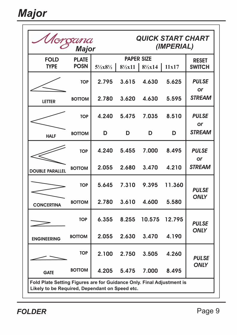
QUICK START CHART(IMPERIAL)
FOLD
LETTER
TYPE
PLATE
POSN
TOP
BOTTOM
PAPER SIZE
2.795 3.615 4.630
RESET
SWITCH
PULSE
STREAM
or
HALF
TOP
BOTTOM
PULSE
STREAM
or
DOUBLE PARALLEL
TOP
BOTTOM
PULSE
STREAM
or
CONCERTINA
TOP
BOTTOM
PULSE
ONLY
ENGINEERING
TOP
BOTTOM
GATE
TOP
BOTTOM
PULSE
ONLY
PULSE
ONLY
Major
Fold Plate Setting Figures are for Guidance Only. Final Adjustment is
Likely to be Required, Dependant on Speed etc.
5½x8½ 8½x11 8½x14 11x17
5.625
2.780 3.620 4.630 5.595
4.240 5.475 7.035 8.510
D D D D
4.240 5.455 7.000 8.495
2.055 2.680 3.470 4.210
5.645 7.310 9.395 11.360
2.780 3.610 4.600 5.580
6.355 8.255 10.575 12.795
2.055 2.630 3.470 4.190
2.100 2.750 3.505 4.260
4.205 5.475 7.000 8.495
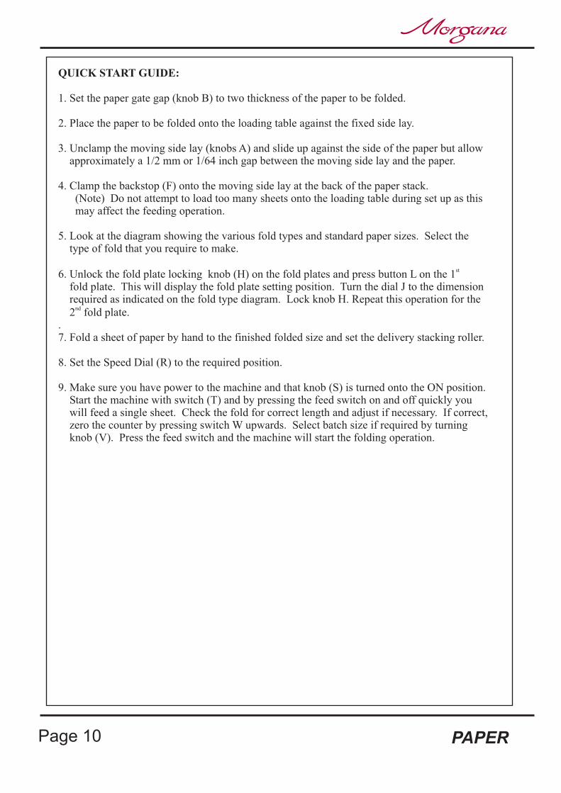
QUICK START GUIDE:
1. Set the paper gate gap (knob B) to two thickness of the paper to be folded.
2. Place the paper to be folded onto the loading table against the fixed side lay.
3. Unclamp the moving side lay (knobs A) and slide up against the side of the paper but allowapproximately a 1/2 mm or 1/64 inch gap between the moving side lay and the paper.
4. Clamp the backstop (F) onto the moving side lay at the back of the paper stack.(Note) Do not attempt to load too many sheets onto the loading table during set up as thismay affect the feeding operation.
5. Look at the diagram showing the various fold types and standard paper sizes. Select thetype of fold that you require to make.
6. Unlock the fold plate locking knob (H) on the fold plates and press button L on the 1fold plate. This will display the fold plate setting position. Turn the dial J to the dimensionrequired as indicated on the fold type diagram. Lock knob H. Repeat this operation for the
2 fold plate..7. Fold a sheet of paper by hand to the finished folded size and set the delivery stacking roller.
8. Set the Speed Dial (R) to the required position.
9. Make sure you have power to the machine and that knob (S) is turned onto the ON position.Start the machine with switch (T) and by pressing the feed switch on and off quickly youwill feed a single sheet. Check the fold for correct length and adjust if necessary. If correct,zero the counter by pressing switch W upwards. Select batch size if required by turningknob (V). Press the feed switch and the machine will start the folding operation.
st
nd
Page 10 PAPER
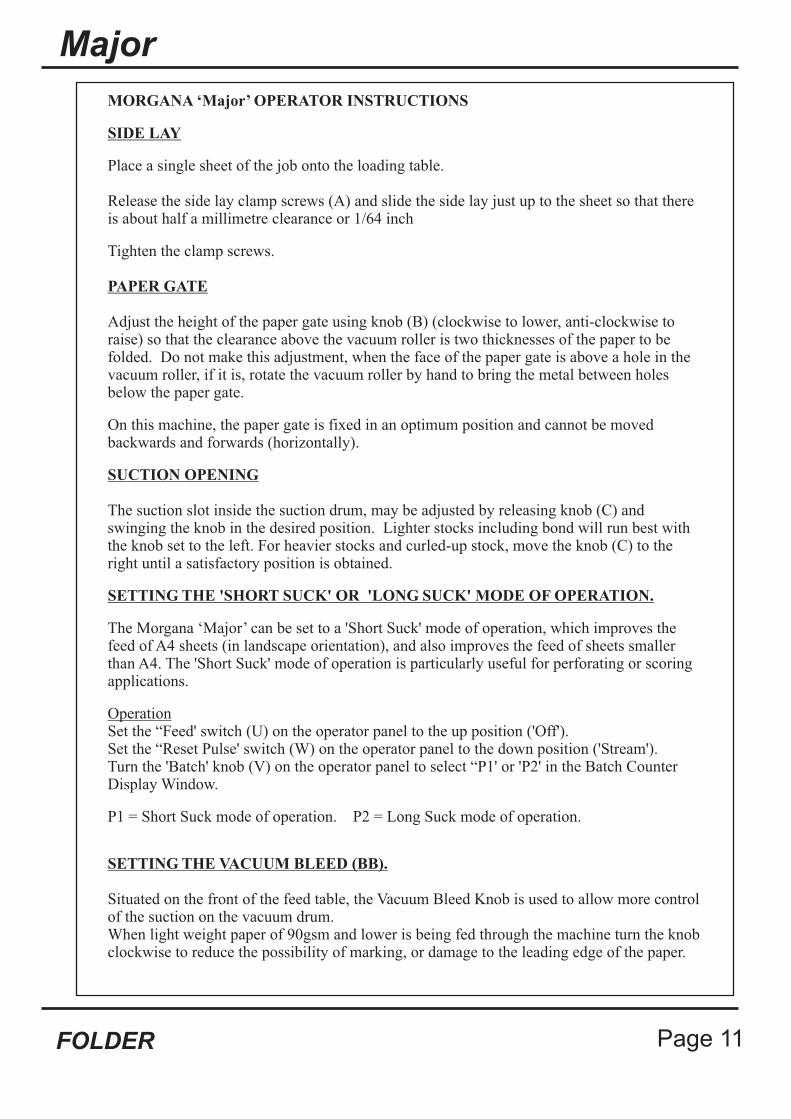
MORGANA ‘Major’ OPERATOR INSTRUCTIONS
SIDE LAY
PAPER GATE
SUCTION OPENING
SETTING THE 'SHORT SUCK' OR 'LONG SUCK' MODE OF OPERATION.
Place a single sheet of the job onto the loading table.
Release the side lay clamp screws (A) and slide the side lay just up to the sheet so that thereis about half a millimetre clearance or 1/64 inch
Tighten the clamp screws.
Adjust the height of the paper gate using knob (B) (clockwise to lower, anti-clockwise toraise) so that the clearance above the vacuum roller is two thicknesses of the paper to befolded. Do not make this adjustment, when the face of the paper gate is above a hole in thevacuum roller, if it is, rotate the vacuum roller by hand to bring the metal between holesbelow the paper gate.
On this machine, the paper gate is fixed in an optimum position and cannot be movedbackwards and forwards (horizontally).
The suction slot inside the suction drum, may be adjusted by releasing knob (C) andswinging the knob in the desired position. Lighter stocks including bond will run best withthe knob set to the left. For heavier stocks and curled-up stock, move the knob (C) to theright until a satisfactory position is obtained.
The Morgana ‘Major’ can be set to a 'Short Suck' mode of operation, which improves thefeed of A4 sheets (in landscape orientation), and also improves the feed of sheets smallerthan A4. The 'Short Suck' mode of operation is particularly useful for perforating or scoringapplications.
Set the “Feed' switch (U) on the operator panel to the up position ('Off').Set the “Reset Pulse' switch (W) on the operator panel to the down position ('Stream').Turn the 'Batch' knob (V) on the operator panel to select “P1' or 'P2' in the Batch CounterDisplay Window.
P1 = Short Suck mode of operation. P2 = Long Suck mode of operation.
Operation
SETTING THE VACUUM BLEED (BB).
Situated on the front of the feed table, the Vacuum Bleed Knob is used to allow more controlof the suction on the vacuum drum.When light weight paper of 90gsm and lower is being fed through the machine turn the knobclockwise to reduce the possibility of marking, or damage to the leading edge of the paper.
Major
Page 11FOLDER
SETTING THE SPEED. (Speed setting dial ‘R’)
0 = Slow (Use for Delicate Paper and accuracy)3 = Recommended Perforating Speed
10 = Fast (Use for Medium Weight Paper)
Use setting number 6 for normal use.Note:-
AIR DISTRIBUTION KNOB (D)
AIR SEPARATION KNOB (E)
BACK STOP (F)
FOLD PLATES
Depending on the length of the sheet, the air distribution knob (D) should be rotated to supplythe air to the correct ports as follows -
Position 1 - This is for short sheets A5 or 8" long with only port 1 openPosition 2 - This is for sheets A4 or 11" long with the front port and port 2 openPosition 3 - This is for the longest sheets A3 or 17" with the front port and port 3 open.Position 0 - In this position, only port 2 is open and can be used on long sheets
with the curl up where you need to blow air into the centre of the stack.
These setting positions are only a guide and some experimentation may obtain a better resultwith non-standard settings.
.This knob controls the amount of air that is fed to the paper. The machine would normally runwith this knob set at the ‘High’ position. If the machine is run with less than approximately 20sheets on the loading table, or running the job to the last sheet, this knob should be set to thelow position.
This is placed up to the end of the paper stack and clamped to the moving side lay (G).
Fit the fold plates into their respective positions (long fold plate upper and short plate lower), bylocating the front pins (I) into the long slots and carefully sliding forwards (without twisting)until the rear pins can be located into the short slots. When fully in position, pull down the foldplate to lock into position.
Set the fold length by releasing the lock knob (H) and rotating the dial (J). The fold length maybe read on a manual plate directly off the scale (K) or for the digital fold plate by pressing the'ON' button (L). More precise movements will be registered by pressing 'micro' button M whichwill display increments (of one tenth of a millimetre, or for imperial machines one hundredth ofan inch). To preserve battery life, the display will switch off after 30 seconds.
If the fold needs to be tilted, this can be achieved by releasing knob (N) and turning the dial (J),( ). Moving the dial to the + direction will increase the fold lengthon the operator side.
(Note) Position 1 feeds most paper stocks and sizes, thus the air distribution knob can beleft in this position for most jobs.
Do not release lock knob (H)
Fitting
Settings
Fold plate Tilt
Page 12 PAPER
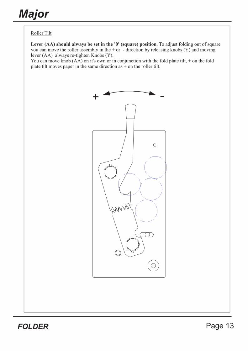
Roller Tilt
Lever (AA) should always be set in the '0' (square) position. To adjust folding out of squareyou can move the roller assembly in the + or - direction by releasing knobs (Y) and movinglever (AA) always re-tighten Knobs (Y).You can move knob (AA) on it's own or in conjunction with the fold plate tilt, + on the foldplate tilt moves paper in the same direction as + on the roller tilt.
+ -
Major
Page 13FOLDER
Deflect
Stacking Roller
Emergency Stop Switch (S)
Main Switch (T)
Feed Switch (U)
Batch Knob (V)
The second (short) fold plate has the ability to be shut off into a deflect position to enablesingle folds to be achieved without removing the fold plate from the machine. To set the plateto deflect, first ensure that the tilt is set at zero, then after releasing the lock knob (H), keepwinding the dial (J) to minimum length until it stops, then tighten the lock (H). The digitalplate will show a series of dashes --- in the window.
The stacking roller must be set according to the length of the folded work. The roller is movedby releasing knob (P) while sliding the block Q to the required position. You should adjust theroller position so that when the work is stopped by the stacking roller, it lies flat on the deliverywithout lying on the sloping plate (R) and without the green belts showing between the slopingplate (R) and the folded sheet.
This switch also serves as the main isolator and when the machine is switched off at the end ofthe days running, press this switch to isolate the machine. To switch back on, rotate the switchhead clockwise.
The main switch (T) will run the whole machine. This switch incorporates a circuit thatswitches off every 100 seconds whilst the feed switch U is in the off position. The main switchmay disengage seemingly at random but this is a normal function and may be instantly re-engaged.
Switches the feed on and off.
The batch knob is a rotary switch and turning the knob slightly so that it moves one positionwill cause the display to show the set batch quantity. Moving the knob further will change thebatch quantity in multiples of 10 up to 990. Stopping the feed in the middle of a batch will notaffect the batch. When the machine batches, the feed will stop and the display will show thebatch quantity with a series of dashes. Feeding will resume after a short period. If batching isnot required, turn the batch knob (V) until it reads 0 in the display panel. When 0 is shownafter turning batch knob (V) the counter will only total count.
Page 14 PAPER
Major
Page 15FOLDER
Reset Switch (W)
Overlap
Speed Control (R)
This switch has two functions:
To set the type of feed, either pulse or stream
To zero the total and batch counts
The switch has three positions:
Operating the switch upwards will zero the total count and if part way through a batch, itwill reset the batch count.
After operating the switch upwards, it will spring back to its centre (default) position. Inthis position the feeder pauses between each sheet fed, leaving a gap between sheets. Thisis called pulse feed.
Operating the switch to its lowest position will change the feed to continuous with thesheets following directly behind each other. This is called stream feed.
(Note) In the pulse position a gap of 160 mm will be set between each sheet as it is being fedinto the machine. This gap prevents sheets over lapping inside the fold plates, which lessens thechance of static being generated and will decrease paper jams.Zigzag / concertina, engineering and gate folds should only be run on pulse. By holding switch(W) down, the feed mode will switch to stream feed which will feed paper with little or no gapbetween the sheets. Stream feed will increase productivity but folding accuracy may be slightlyimpaired. Only use stream on letter, half or double parallel folds.
The pulse feed will cope with all types of fold including perforating.
The machine has a built in system that will detect any sheet that overlaps another sheet by atleast 20mm. When this happens, feeding will stop and the main switch will switch off,preventing serious jams and the display will show 'O-LAP'. Note that this is not a doubledetector and will not detect all double sheet feeds. However the overlap system is an indicationof a tendency to double sheet feed and therefore the paper gate should be lowered slightly andthe paper stack should be fanned out more thoroughly.
The machine has variable running speeds, which are selected using the knob (R). Turn theknob clockwise to increase the speed and anti-clockwise to reduce the speed. The slow speed isrecommended when running work that is difficult to stack, for example when perforating orfolding an engineering type fold.
��
�
�
�

PLUG-IN PERFORATOR
FITTING PERFORATER BLADES
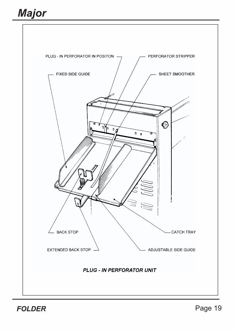
The plug in perforator unit is used for perforating scoring and when folding card cover stock.
Remove the second fold plate and fit the catch tray in position by hooking it over the openingfor the second fold plate. The plug in perforator unit then locates the same as the fold plate andagain, take care not to twist when fitting into position. You may need to turn the hand wheeland push the perforator unit inwards to engage the drive gear.
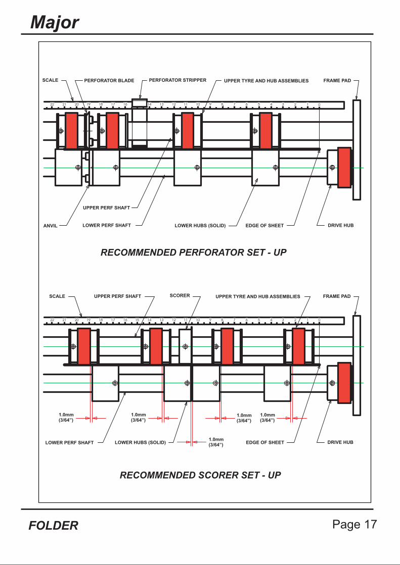
For all applications, the unit is set on the bench using the scale to indicate positions of theblades and hubs. It is important to spread the hubs evenly across the width of the work toreduce the risk of paper jams.When perforating or scoring without folding, the first fold plate must be removed and replacedwith the second fold plate. Ensure that the tilt is at zero and set the second fold plate to deflect.
The perforator blades are split into two matching halves and are fitted to the upper hubs asshown in the drawing using the four screws supplied.
A hardened anvil is fitted to the lower hub as shown in the drawing also using the four screwssupplied. Again the anvils are made from matching halves. Note - Do not mix matching halvesof blades or anvils
Important - THE PERFORATOR BLADES ARE VERY SHARP AND GREAT CAREMUST BE TAKEN WHILST HANDLING.
Page 16 PAPER
1522 21 20 19 18 17 16 4 3 2 1 0567891011121314
22 21 20 19 18 17 16 4 3 2 1 0567891011121314
RECOMMENDED PERFORATOR SET - UP
RECOMMENDED SCORER SET - UP
LOWER PERF SHAFT LOWER HUBS (SOLID)
1.0mm(3/64”)
1.0mm(3/64”)
1.0mm(3/64”)
1.0mm(3/64”)
1.0mm(3/64”)
EDGE OF SHEET DRIVE HUB
FRAME PADUPPER TYRE AND HUB ASSEMBLIESSCORERUPPER PERF SHAFTSCALE
EDGE OF SHEET DRIVE HUBLOWER HUBS (SOLID)LOWER PERF SHAFT
UPPER PERF SHAFT
SCALE UPPER TYRE AND HUB ASSEMBLIES FRAME PAD
ANVIL
PERFORATOR BLADE PERFORATOR STRIPPER
Major
Page 17FOLDER
SETTING PERFORATORS
SCORING
Upper and lower hubs can be positioned on the shaft by unscrewing the 2mm-grub screw.Slide the hub with the blade attached along, the shaft into position to correspond to thework using the scale as a guide. For example, to perforate 20mm from the edge of an A4sheet, you would set the blade at 190mm (210 minus 20). When positioned re-tighten the2mm-grub screw. -
Slide the hub with the anvil, up to the perforator blade and the remaining upper and lowerhubs, set as the drawing, remembering to spread them to support the sheet fully across itswidth.
Clip the perforator stripper adjacent to the upper hub as shown. Plug the unit intoposition, fit the sheet smoother into position to hold the sheets down and run the machineat the slow speed to check position.
Adjust the backstop and side guide to suit the work.For work longer than the backstop will allow, remove the backstop and use the extendedbackstop that is located underneath the catch tray.
There is a full range of perforator blades available as follows:
For fine perforation 56 tooth - Part Number 1.99-41For Paper 28 tooth - Part Number 1.99-12For heavier Stock 20 tooth - Part Number 1.99-10For use with blades Anvil - Part Number 1.99-35Slitter set for cutting - Part Number 1.99-13
It is possible to score work using the plug in perforator. The scorers are split in twohalves, fitted to the upper shaft and set as shown in the drawing using the scale on theunit as a guide to position. The lower hubs are moved up to but just clear of the scoringblade. The actual gap is critical and may require some experimentation to obtain asatisfactory score line. As with perforating, the remaining hubs must be spread to supportthe sheet fully across its width.
Scorers available:
Type A Part Number 6.99-05 for most cardType B Part Number 6.99-06 for deep scoreType D Part Number 6.99-09 for paper
Important Do Not Over Tighten This Grub Screw
Page 18 PAPER
Major
Page 19FOLDER
FOLDING CARD
PAPER JAMS
For best results, the card material should always be printed cross grain as this causes lessresistance when folding. Pre scoring of card stock is also recommended
By using the plug in perforator unit to deliver card, the problem of the stock curling will beminimised. Set the backstop and side guide to suit the work. It is recommended that whenfolding card, the machine is set to batch after twenty sheets, which will allow easy off loading.For longer runs a optional rear delivery belt stacker (Assy. No. 9-09-01) is recommended to beused.
In the event of a paper jam, the sensor will cut out the main switch. The main fold rollers arelinked to a clutch, which will prevent sheets continuing to feed.
If for some reason a piece of paper jams in the machine, remove and check inside the foldplates. If there is paper jammed around the fold rollers take hold of a roller and wind them byhand to remove the jam. If it is impossible to wind the roller by hand, remove the rollerassembly as described below. After clearing a paper jam, always check inside the fold plate(see Fold Plate Section) to make sure no torn pieces of paper are jammed inside the plate.
ROLLER ASSEMBLY - REMOVAL
The complete roller assembly unit can be removed from the machine simply by unscrewing theknobs (Y) on each side and taking hold of the rear roller and lifting out the unit. This isbeneficial to clear paper jams, and to clean the roller for maintenance.With the roller assembly removed, the safety circuit prevents the machine from running. Cleanthe rollers with a stiff brush between the grooves using the QD wash supplied with themachine. Replace the roller unit in the reverse sequence.
Page 20 PAPER
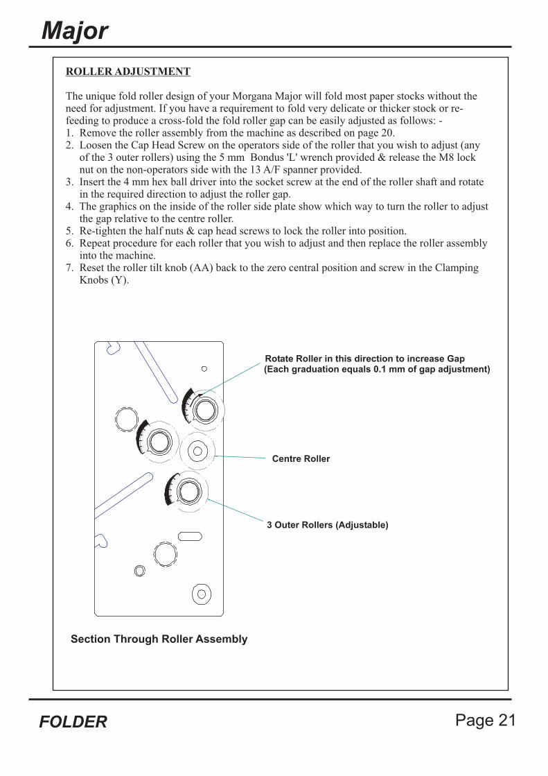
ROLLER ADJUSTMENT
The unique fold roller design of your Morgana Major will fold most paper stocks without theneed for adjustment. If you have a requirement to fold very delicate or thicker stock or re-feeding to produce a cross-fold the fold roller gap can be easily adjusted as follows: -1. Remove the roller assembly from the machine as described on page 20.2. Loosen the Cap Head Screw on the operators side of the roller that you wish to adjust (any
of the 3 outer rollers) using the 5 mm Bondus 'L' wrench provided & release the M8 locknut on the non-operators side with the 13 A/F spanner provided.
3. Insert the 4 mm hex ball driver into the socket screw at the end of the roller shaft and rotatein the required direction to adjust the roller gap.
4. The graphics on the inside of the roller side plate show which way to turn the roller to adjustthe gap relative to the centre roller.
5. Re-tighten the half nuts & cap head screws to lock the roller into position.6. Repeat procedure for each roller that you wish to adjust and then replace the roller assembly
into the machine.7. Reset the roller tilt knob (AA) back to the zero central position and screw in the Clamping
Knobs (Y).
Centre Roller
3 Outer Rollers (Adjustable)
Rotate Roller in this direction to increase Gap(Each graduation equals 0.1 mm of gap adjustment)
Section Through Roller Assembly
Major
Page 21FOLDER

SENSOR CLEANING
FOLD PLATES - MAINTENANCE
The sensors, that detect and count the sheets, are located on the end of the ball holderjust next to the fold roller unit. If the counter is failing, the sensors can be accessed forcleaning by removing the roller assembly as described above. Clean by using a softbrush or damp cloth.
The fold plates can be opened up for maintenance, cleaning, etc by removing the lockknob (H) and removing the two bolts (Z). The fold plate will then open up to enablepaper jams to be removed or cleaning on digital fold plates, replacement of the battery.(Battery Part Number 613.379)
Page 22 PAPER
FOLDING TIPS AND TROUBLE SHOOTING:
SHEETS DIFFICULT TO FEED
DOUBLE SHEET FEEDING
FOLD IS NOT SQUARE OR CONSISTANT
Check that you have not got too many sheets in the feeder. Heavy-coated stock will not feed ashigh a pile as for example 80-gsm copier paper.
Make sure the moving side lay is not pushed in too tightly against the paper. Similarly, if themoving side lay is set too far away from the paper stack, this will allow the air to escapeinstead of blowing through the paper.
Make sure that the gap under the paper gate (B) is not set too low.
Turn the Air separation knob (E) to the high position.
Make sure that air distribution knob (D) is set correctly.
If the paper width varies you may need to trim the sheets to the same size.
If the paper is curling upwards the suction drum may not be able to pull the sheet downward towrap around the drum for efficient feeding. You may need to bend the sheets downward priorto loading.
Make sure the gap under the paper gate (B) is not set too high.
Make sure the air distribution knob (D) and the air separation knob (E) are at the correctsetting.
In extreme cases you may need to separate the sheets prior to loading.Make sure you run on Pulse not Stream.
Check the sheets are all exactly the same size and are square before folding as you can onlyfold accurately if the material is consistent.
Make sure you have no foreign bodies such as fragments of torn paper inside the fold plates orthe fold rollers.
Check that the fold plates are locked and located securely and that the tilt mechanism is set tozero and locked.
Check that the stock is not too heavy, particularly if folding against the grain.
Check that the moving side lay is set up to the paper, without too much gap that will allow thesheets to twist
Major
Page 23FOLDER
PAPER WILL NOT STACK CONSISTENTLY:
PAPER WILL NOT DEFLECT WHEN USING ONE FOLD OR PERFORATING:
TOTAL AND BATCH COUNTER NOT WORKING:
O-LAP KEEPS APPEARING ON COUNTER BOARD
Make sure the feed is consistent before attempting adjustments to the stacker.
Set the stacking roller position as described in the manual. Sometimes a small repositioning ofthe roller will improve the stacking.
If the paper is too curly when being delivered, place the catch tray and plug in perforating unitwith blades disengaged into position and deliver out the back. This applies to single foldapplications only. If two folds are required, you may need to reduce the weight of stock toachieve the desired results.
Check to make sure that the second plate is being used as the deflector.
Make sure that the plate is located securely and that the deflector bar is wound right to the end.
Set the tilt mechanism to zero
Check that the material is not too heavy to deflect.
Clean the sensors as described in the manual.
If the overlap keeps tripping in and cutting off the machine, first check you are not feedingdoubles and reset the feeder.
Overlap tripping can also mean that the machine is slowing slightly which may mean thematerial is too heavy.
Check that you have no foreign bodies or torn paper stuck inside the plates or machine.
Page 24 PAPER

NO POWER TO MACHINE
MAIN SWITCH CUTS OUT:
FOLD ROLLER REPLACEMENT:
If control panel display fails to come on, check that isolator switch (S) is not pressed in. Torelease, turn knob clockwise.
Check power supply to the machine.
The feeder will cut out automatically after 100 seconds if the main switch is left on without thefeed switch being activated.
The compressor inside the machine requires up to 28 amps to start running. You must have themachine plugged directly into a 30-amp ring main. Do not attempt to run the machine with anextension lead.
The main switch will cut out if you have a paper jam or overlap is indicated.
Your Morgana Major has been designed to make fold roller replacement an easy and low costoperation. Your local sales agent will be able to supply you with a complete replacement rollerassembly which allows you to change the roller assembly yourself as described in the rollerassembly removal section of this manual. You will need to send back to your agent theexisting roller assembly.
Major
Page 25FOLDER

Page 26 PAPER
DISPATCH KIT9-95-069-95-07
(EEC)(USA)
ITEM PART NUMBER QTY DESCRIPTION
1
2 90-103 1 OPERATORS MANUAL - Major
3 90-018 1 ROLLER CLEANING KIT
4 78-007 1 BACK STOP ASSEMBLY
5 1 - 99 - 35 1 ANVIL SET
6 1 - 99 - 41 1 PERFORATING SET - 56T - SLITTING
12
620-004 1 HEXAGON BALL DRIVER 4mm
14
16 620-032 1 COMBINATION SPANNER 13mm A/F
17 624-018 1 DISPATCH BOX
7
620-007 1 HEXAGON BALL DRIVER 2mm
620-025 1 BONDUS ‘L’WRENCH 2.5mm
8
6 - 99 - 05
613-316
1 SCORING SET - TYPE A
1 POWER CORD - (EEC)
10
650-015 1 POWER CORD - (USA)
15 620-027 1 BONDUS WRENCH 5mm
13 620-020 HEXAGON BALL DRIVER 2.5mm1
620-006 1 ALLEN KEY 1mm11
9 617-004 5 GLASS BALL
613-453 1 POWER CORD - (NAGEL & FRENCH))
Major
Page 27FOLDER
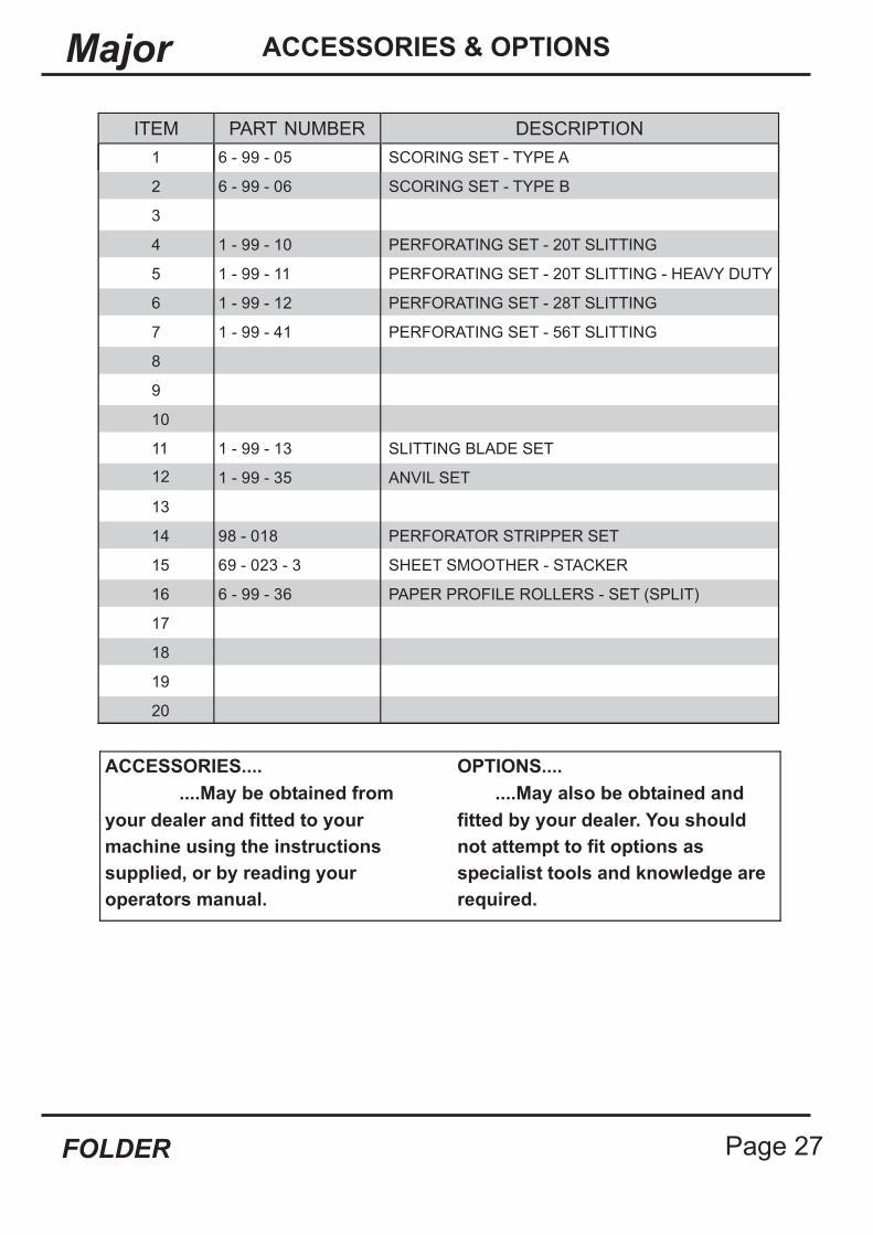
ACCESSORIES & OPTIONS
ACCESSORIES....
your dealer and fitted to your
machine using the instructions
supplied, or by reading your
operators manual.
OPTIONS....
....May also be obtained and
fitted by your dealer. You should
not attempt to fit options as
specialist tools and knowledge are
required.
....May be obtained from
ITEM PART NUMBER DESCRIPTION
1 6 - 99 - 05 SCORING SET - TYPE A
2 6 - 99 - 06 SCORING SET - TYPE B
3
4 1 - 99 - 10 PERFORATING SET - 20T SLITTING
5 1 - 99 - 11 PERFORATING SET - 20T SLITTING - HEAVY DUTY
6 1 - 99 - 12 PERFORATING SET - 28T SLITTING
7 1 - 99 - 41 PERFORATING SET - 56T SLITTING
8
9
10
11 1 - 99 - 13 SLITTING BLADE SET
12 1 - 99 - 35 ANVIL SET
13
14 98 - 018 PERFORATOR STRIPPER SET
15 69 - 023 - 3 SHEET SMOOTHER - STACKER
16 6 - 99 - 36 PAPER PROFILE ROLLERS - SET (SPLIT)
17
18
19
20

Page 28 PAPER
RECOMMENDED SPARES
DESCRIPTIONPART No.
FUSE - 3.15A - 20x5mm - FAST BLOW CERAMIC
MAGNETIC ACTUATOR601-021
FOOT - Black606-028
SCALLOP KNOB - Black606-030
TWIN GRIP TIMING BELT607-022
TIMING BELT607-025
TIMING BELT607-026
TIMING BELT607-027
‘O’ RING609-011
‘O’ RING609-013
‘O’ RING609-014
‘O’ RING609-023
FUSE HOLDER613-059
MOTOR SPEED CONTROLLER - PCB613-184
CAP613-237
SOLENOID COIL613-255
EMERGENCY STOP SWITCH613-365
SWITCH 10 AMP - 12v COIL - (EEC)613-376
613-383 SWITCH 16 AMP - 12v COIL - (USA)
KNOB613-385
NUT COVER613-386
681-005
MOTOR SHAFT ASSY - DC Drive - Extended91-068-02
TRANSPORT BELT - Delivery92-010
DRIVE BELT - Delivery - Flat 12mm92-027-01
FEED BELT93-021
DRIVE BELT - Vacuum Roller93-022
SMOOTHER - Delivery93-028
LOCK PIN ASSEMBLY - Side Lay94-028
LENS - Display95-020
CONTROL PCB - Junior95-021
SWITCH ASSEMBLY - Reset / Pulse / Stream95-046
SWITCH ASSEMBLY - Feed95-047
ROTARY ENCODER ASSEMBLY95-049
POT & LEAD ASSY. - Motor Speed95-109
95-138
or

Page 29FOLDER
Major RECOMMENDED SPARES
DESCRIPTIONPART No.
NOTE....
The items listed above represents parts which are subject to wear, loss, oraccidental damage, and is included for your guidance only.
Replacement of parts fitted to your machine require specialist knowledge andshould therefore be entrusted to your dealer.
CHOKE ASSY. - PM63 - 3.5A95-112
PLUNGER & SPRING ASSY95-129-01
HOSE - Air Seperation95-132
HOSE - Vacuum95-133
FOLD ROLLER ASSEMBLY - Standard96-028-02
FOLD ROLLER ASSEMBLY - Bottom96-049-02
DRIVE BELT - Large Roller Drive96-031
POSITIONAL DISPLAY - PCB97-040
POT & LEAD ASSEMBLY97-075

Page 30 PAPER
Technician Maintenance
It is recommended that your Morgana Major is fully serviced at leastonce every six months by a factory trained Service Engineer.

Page 31FOLDER
MajorPRODUCT RECYCLING & DISPOSAL
Application of this symbol on your equipment is confirmation that you
must dispose of this equipment in compliance with agreed national
Procedures.
In accordance with European legislation end of life electrical and
electronic equipment subject to disposal must be managed within
agreed procedures.
Prior to disposal please contact your local dealer or representative for
end of life take back information.
European Union
Disposal Information for Commercial Users
Disposal Information for Domestic Users
Application of this symbol on your equipment is confirmation that
you should not dispose of the equipment in the normal household
waste stream.
In accordance with European legislation, end of life electrical and
electronic equipment subject to disposal must be segregated
from household waste.
Private households within EU Member States may return used
electrical and electronic equipment to designated collection
facilities free of charge. Please contact your local disposal
authority for information.
In some Member States when you purchase new equipment your
local retailer may be required to take back your old equipment
free of charge. Please ask your retailer for information.
Other Countries
Please contact your local waste authorities and request disposal information.