paper 4 - p302
TRANSCRIPT

8/13/2019 Paper 4 - p302
http://slidepdf.com/reader/full/paper-4-p302 1/6
Abstract –
As poly-phase motor drive system is become more
popular and practical leads to its advantages. This paper
proposes a five-phase induction motor (IM) drive system fed
from five-phase matrix converter (MC) with three-phase
grid input. The modulation strategy of this converter is
based on indirect space vector modulation (ISVM). The
analysis of this strategy was carried out. Simulation model is
developed and used during the design process of the
converter prototype. The implemented converter was based
on discrete semiconductors. A five-phase induction motor
has been designed and implemented in the lab. A laboratory
system has been implemented based on digital signal
processor (DS1104). Experimental results are given, and
then the drive system performance is discussed.
Keywords - five-phase matrix converter, indirect space
vector modulation, five-phase induction motor
I. I NTRODUCTION
owadays, the interest in poly-phase motor drive
system has been increased due to several
advantages over than of a three-phase drive
system. These advantages are inherent to the
own structure of the machine, such as reducing the
amplitude and increasing the frequency of torque
pulsations, reducing the rotor harmonic current losses,
and lowering the dc link current harmonics [1-3]. As a
result, there is an urgent need for the AC-AC poly-phase power converters to transform a constant voltage constantfrequency three-phase supply into a variable voltage with
variable frequency (VVVF) output required for these
machines.
The MC is a direct m-phase to n-phase converter, was
firstly introduced in 1976 by [4] and it steadily growth,
pushed by the progress of the power electronics devicetechnology. In recent years the MC has received an
increased amount of interest and has been studied
intensely as an alternative to AC-DC-AC power
converters. After almost three decades of intensive
research, the development of MC has been involved in
industrial applications. In 2008, Yaskawa Company inJapan introduces the first product of three-phase MC.
Until the time of writing this paper, more than 1350
papers directly related to the MC technology are
published in IEEE journals and conferences. This data has
been collected from IEEE explore data base. It should be
mentioned here, the most common configuration of the
MC discussed in the literature is the three-phase to three-
phase, little attention has been aid on the development of
MC with output more than three, except in [5] – [11].
This paper proposes a three-phase to five-phase
matrix converter supplies a five-phase induction motor
S. M. Dabour, A. Hassan and E. M. Rashad are with the Department ofElectrical Power and Machines, Faculty of Engineering, Tanta
University, Tanta, 31521, Egypt. (e-mail: [email protected]).
drive system using V/f control. The converter modulationstrategy is based on ISVM technique. The model of
a five-phase induction motor has been introduced. The
overall drive system has been implemented using Matlab/
Simulink. Then, the MC control algorithm is compiled toreal time system based on DS1104 dSPACE card. The
generated signals from the card are applied to the
implemented MC through an interface circuit. Full details
of the design and implementation of the MC was
introduced in [8 and 12]. Finally the experimental results
are given and discussed.
II. DIRECT FIVE-PHASE MC TOPOLOGY
The five-phase MC is a direct three-phase to five-phase
through one stage; it utilizes 15th
switches, as shown in
Figure 1. Each of the 15th
switches depicted is a
bidirectional switch (BDS), which are connected so that,
any of the input phases (A, B, and C) can be connected to
any of the output phases; (a-e) for a given switching. Withthe 15
th BDS, the MC has 2
15 different switching states.
Some of the basic rules must be regarded when applying
different switching states to the MC at any switching
time. These rules are: (1) input phases must never be
shorted, and (2) output phases must not be left open, due
to the inductive nature of the load. Due to these rules, the
switching states reduce to 35
different switchingcombinations for connecting the output to the input. The
output voltages (va - ve) and the input currents (i A i BiC ) are therefore derived directly from the input voltages
(v A v B vC ), and the output currents (ia - ie) as follows:
= . (1)
where, S is the modulation matrix or the duty cycles of
the switches.
=
(2)
SaA SbA ScA SdA SeA
SaB SbB ScB SdB SeB
SaC SbC ScC SdC SeC
V A
V B
V C
a
b
cd
e
M
C f
L f Switching Matrix
Input Filter
Figure 1: Direct five-phase matrix converter topology.
Five-Phase Induction Motor Drive System Fed from Five-
Phase Matrix-Converter
Sheriff M. Dabour, Abd El-Wahab Hassan and Essam M. Rashad, Senior Member, IEEE 1
Proceedings of the 15th International Middle East Power Systems Conference (MEPCON’12), Alexandria University, Egypt,December 23-25, 2012, Paper ID 302, pp 898-903

8/13/2019 Paper 4 - p302
http://slidepdf.com/reader/full/paper-4-p302 2/6
III. I NDIRECT TOPOLOGY OF FIVE-PHASE MC
This topology to model the MC actually corresponds to
regard the MC as a double-PWM converter without any
DC-Link energy storage, where MC was described to an
equivalent model combining current source rectifier andvoltage source inverter connected through virtual dc link
and it was first proposed by [13] for three-phase to three-
phase MC, and by applying this algorithm on the directfive-phase MC, the resulting indirect five-phase MC is
shown in Figure 2. The rectifier stage has the same
topology of the three-phase rectifier with six switches, S1
~ S6, and the Inverter stage has a standard five-phase
voltage source inverter topology consisting of ten
switches, S7 ~ S16. Both power stages are directly
connected through virtual dc-link and inherently provide
bidirectional power flow capability because of its
symmetrical topology.
IV. ISVM OF THE PROPOSED CONVERTER
The ISVM technique constructs the desired sinusoidal
output five-phase voltage by selecting the valid switchingstates of a MC and calculating their corresponding on-
time durations. The basic idea of this technique is to
decouple the control of the input current and the control
of output voltage. This is done by splitting the modulation
matrix S for the converter into the product of a rectifier
transfer function R and an inverter transfer function I .
The modulation matrix for the MC is thus defined as
following [3], [4]:
= . (3)
Where =
7 8
9 10
1113
15
1214
16
& = 1
3
5
2 4 6 (4)
Based on ISVM the following sections describe two
independent space vector modulations for three-phase
current source rectifier, and five-phase voltage source
inverter stages and then the two modulation results are
combined to modulate the five-phase MC.
Space Vector Rectifier (SVR)
The rectifier converts the input three-phase voltage to
DC-voltage. At the same time the rectifier algorithm
assures the input currents to be sinusoidal. This section
introduces a SVM in the rectifier stage. The rectifier partof the equivalent model shown in Figure 2 can be
assumed to be a stand-alone current source rectifier.
Figure 2: Indirect Five-phase Matrix converter topology.
The rectifier switches, S 1 ~ S 6 can have only possible
nine allowed combinations to avoid an open circuit at the
dc link rails. The nine combinations can be divided intosix nonzero input currents which are active vector I 1 ~ I 6
and three zero input currents which are zero vector I 7 ~ I 9
Figure 3 shows current space vector hexagon. The
reference input current vector (Ii*) within a sector of the
current hexagon (Figure 3) is synthesized by impressing
the adjacent switching vectors Iγ and Iδ with the dutycycles dγ and dδ, respectively. If the input currents are
considered constant during a short switching interval (TS),
the reference vector can be expressed by the current-time
product sum of the adjacent active vectors as;
∗ = . + . + . (5)
Thus, the duty cycle of the active vectors are written as;
= .sin3−
= . sin() (6)
= 1
−(
− )
where, θC indicates the angle of the reference current
vector within the actual hexagon sector. The mC is thecurrent modulation index and defines the desired current
transfer ratio such as:
0 ≤ ≤ 1 & =∗
Space Vector Inverter (SVI)
This section introduces a SVM in the inverter stage.
Consider the inverter part of the equivalent model in
Figure 2 as a standalone VSI supplied by a dc voltage
source, as shown in Figure 4. The output voltage space
vector is expressed as a function of phase voltages asfollows:
=2
5 + . + 2 . + 3. + 4 .
= (7)
where, = 2/5 , V out is the output voltage, and is
the space vector angle. The inverter switches, S 7 – S 16
have only thirty two allowed combinations to avoid a
short circuit through five half bridges. The thirty two
combinations have thirty nonzero output voltages or
active vectors (V 1 to V 30) and two zero output voltages or
zero vector V 0. The discrete thirty two space vectors can
be represented as a decagon in a complex plane shown inFigure 5.
Figure 3: Rectifier current hexagon
S 1
S 2
S 3
S 4
S 5
S 6
S 7
S 8
S 9
S 10
S 11
S 12
Rectifier Stage Inverter Stage
V DC
A
B
C
abc
+
-
S 13
S 14
S 15
S 16
d e
I p
In
8/13/2019 Paper 4 - p302
http://slidepdf.com/reader/full/paper-4-p302 3/6
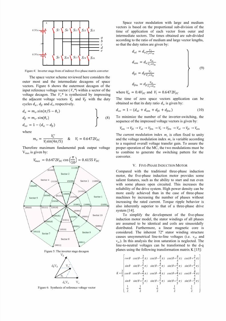
Figure 4: Inverter stage from of indirect five-phase matrix converter
The space vector scheme reviewed here considers the
outer most and the intermediate decagons of space
vectors. Figure 6 shows the outermost decagon of theinput reference voltage vector (V o*) within a sector of the
voltage decagon. The V o* is synthesized by impressing
the adjacent voltage vectors and with the duty
cycles , and d ov respectively.
= .sin/5 − = . sin() (8)
= 1 − ( − )
where
=∗
sin(4/5) & = 0.6472
Therefore maximum fundamental peak output voltage
Vmax is given by:
= 0.6472 cos 10
= 0.6155
Figure 5: The inverter stage decagon
Figure 6: Synthesis of reference voltage vector
Space vector modulation with large and medium
vectors is based on the proportional sub-division of the
time of application of each vector from outer andintermediate sectors. The times obtained are sub-divided
according to the ratio of medium and large vector lengths,
so that the duty ratios are given by: =
+ =
+
(9) =
+
= +
where = 0.4 and = 0.6472
The time of zero space vectors application can be
obtained so that its duty ratio is given by:
= 1
−(
+
+
+
) (10)
To minimize the number of the inverter-switching, the
sequence of the impressed voltage vectors is given by:
→ → → → → → → →
The current modulation index mc is often fixed to unity
and the voltage modulation index mv is variable according
to a required overall voltage transfer gain. To assure the
proper operation of the MC, the two modulations must be
to combine to generate the switching pattern for theconverter.
V. FIVE-PHASE I NDUCTION MOTOR
Compared with the traditional three-phase induction
motor, the five-phase induction motor provides some
salient features, such as the ability to start and run even
with some phases open circuited. This increases the
reliability of the drive system. High power density can bemore easily achieved than in the case of three-phase
machines by increasing the number of phases without
increasing the rated current. Torque ripple behavior is
also inherently superior to that of a three-phase drive
system [14].
To simplify the development of the five-phase
induction motor model, the stator windings of all phases
are assumed to be identical and coils are sinusoidallydistributed. Furthermore, a linear magnetic core is
considered. The inherent 72º stator winding structure
causes unsymmetrical line-to-line voltages (i.e. vab and
vac). In this analysis the iron saturation is neglected. The
line-to-neutral voltages can be transformed to the d-q
planes using the following transformation matrix K [15]:
2
1
2
1
2
1
2
1
2
1
5
4
5
2
5
2
5
4
5
4
5
2
5
2
5
4
5
2
5
4
5
4
5
2
5
2
5
4
5
4
5
2
5
2
) sin( ) sin( ) sin( ) sin( sin
)cos( )cos( )cos( )cos( cos
) sin( ) sin( ) sin( ) sin( sin
)cos( )cos( )cos( )cos( cos
K
o
0.5V DC S 7
S 8
S 9
S 10
S 11
S 120.5V DC
abc
+
-
S 13
S 14
S 15
S 16
d e

8/13/2019 Paper 4 - p302
http://slidepdf.com/reader/full/paper-4-p302 4/6
The general equations of five-phase induction motor
can be introduced as follows:
The stator q-d axes voltages are given by:
ds
qs
qs sqsdt
d ir v
(11)
qs
ds
ds sds dt
d
ir v
(12)
For the stationary reference frame ω = 0, substitute intoEquations (11) and (12) yields:
dt
d ir v qs
qs sqs
(13)
dt
d ir v ds
ds sds
(14)
The stator q-d axes flux linkages are given by:
)(
)(
qr qsmqslsqs
qr mqsmlsqr mqs sqs
ii Li L
i Li L Li Li L
(15)
)(
)(
dr dsmdslsds
dr mdsmlsdr mds sds
ii Li L
i Li L Li Li L
(16)
The electromagnetic torque is given by:
dsqsqsdse ii p
T
22
5 (17)
Bdt
d J T T Le (18)
The d-q model of five-phase induction motor in arbitrary
reference frame is shown in the Figure 1.
(a) q-axis circuit
(b) d-axis circuit
Figure 7: q-d Equivalent circuit in arbitrary reference
VI. IMPLEMENTATION OF THE CONVERTER
The switching matrix is realized by 15-bidirectionalswitch, each is composed of a Power MOSFET and four
Fast Recovery Diodes. The interface circuit uses an ultra
speed optocoupler. Figure 8 shows the prototype of a five
phase matrix converter which fabricated in the laboratory
using semiconductor devices. Figure 9 shows main parts
of the proposed system implementation. The system is
composed of mainly three parts, namely; Power, Control,
and Interface circuits.
Figure 8: Photograph of the five-phase matrix converter prototype.
VII. EXPERIMENTAL R ESULTS
Using the previously presented setup, experimental
results have been obtained to confirm the analysis given
in previous sections. Preliminary tests with R-L load has
been carried out to confirm the proper operation of the
designed MC based on SVM control method. The output phases (a-e) of the MC are connected to the five-phase
star connected resistors in series with the three phase
inductors. The per phase load parameters are R = 144 Ωand L = 0.25 H. To test the steady state behavior of the
matrix converter, a small input voltage supply of 100
Volts/line at 50 Hz via an autotransformer is applied. The
voltage transfer ratio set to 0.5 and the reference input
current displacement angle adjusted to zero. The
switching frequency is 1.25 kHz and the sample time is200µsec as a result of the DS1104 capabilities.
Figure 9 shows the measured supply phase voltage
(CH-1) and current (CH-2) waveforms at 10 Hz output
frequency, also the spectrum analysis of the input currentis shown. Because there was no input current filter, the
input current waveform is pulse width modulated. It is
clear that the fundamental component of the input current
is approximately in phase with the input phase voltage
(Figure 9). This is owed to adjusting displacement angle
to zero, which achieves maximum available voltage
transfer ratio using SVM method.
(a)Waveforms
(b)Spectrum Analysis
Figure 9: Input phase voltage (CH1) and input phase current (CH2)waveforms at f o = 10 Hz and spectrum analysis of input current
qsv
sr
qsi
ds
ls L
m L
lr L
dr r )( r r
qr i
dsv
dsi
qs
ls L
m L
lr L
qr r )(
r r dr i
sr

8/13/2019 Paper 4 - p302
http://slidepdf.com/reader/full/paper-4-p302 5/6
Figure 10 shows the output line voltage of the matrix
converter and its spectrum analysis when the output
frequency is 10 Hz. The spectrum shows fundamentalvoltage amplitude of 43.3V (at 10 Hz). The difference
between the measured value (43.3V) and the reference
value of the line voltage (50V) is due to a voltage drops
on the semiconductor elements. Moreover, the employed
DSP capabilities limit sampling time to 200µsec, which
may cause losing some voltage intervals. The amplitudespectrum also shows dominant harmonics components
around switching frequency 1.25 kHz.
(a)Waveforms
(b)Spectrum Analysis
Figure 10: Output line voltages waveforms at f o = 10Hz
Figure 11 shows the output phase current at 10 Hz output
frequency and its spectrum analysis. The output current
has a near sinusoidal waveform with significant 3rd
, 7th
,
9th
, 11th
, 13th
and 17th
harmonic components.
(a)Waveforms
(b)Spectrum Analysis
Figure 11: Output phase-voltages waveforms at f o = 10 Hz
Induction Motor Drive
Experimental results of the five-phase MC fed five-phase
induction motor with scalar control were obtained forvarious operating conditions. The motor parameters are
given in the appendix. The sampling time is kept at
200µsec. Figure 12 shows the motor speed and current
variations for a start up period. The reference frequency is
set at 30 Hz (i.e. 1800 r/min). In this case, the motor is
accelerated from standstill to 1775 r/min.
Figure 12: Motor speed (CH1) and phase current (CH2) of during
start-up period
Figure 13 shows experimental results for a step change infrequency from 30 to 20 Hz after attaining steady-state
condition.
Figure 13: Motor speed (CH1) and phase current (CH2) of during
Step change from 30 to 20 Hz
Finally, Figure 14 shows the experimental results for a
motor speed reversal. Initially the reference frequency is
set at 30 Hz. Then, the speed is reversed to the same
value.
Figure 14: Motor speed (CH1) and phase current (CH2) of speed
reversal

8/13/2019 Paper 4 - p302
http://slidepdf.com/reader/full/paper-4-p302 6/6
VIII. APPENDIX
The Per-phase equivalent circuit parameters of the 380V,
1.1 kW, 2-pole, 50-Hz five- phase induction motor (J =
0.007 kgm2): R s = 14Ω, R r = 4.6Ω, Lls = L lr = 0.8714 H,
Lm = 0.85-H.
IX. CONCLUSION
In this paper a five-phase induction motor drive systemfed by three-phase to five-phase MC has been introduced.
The analysis and implementation of the converter is
carried out. The MC model has been performed in
Matlab/Simulink and then converted to real time codes
for dS1104 card. A preliminary test with R-L load has
been presented to confirm the proper operation of thedesigned converter. Experimental results were introduced
for a five-phase induction motor with V/f control at
various operating conditions. The feasibility of the
proposed system has been verified through experiments
with a good performance and the drive performance can
be improved by reducing sampling time, according to the
controller capabilities.
X. R EFERENCES
[1] M. Jones and E. Levi, “ A literature survey of state-of-the-art in
multiphase ac drives,” in Proc. 37 th Int. UPEC , Stafford, U.K.,2002, pp. 505 – 510.
[2] E. Levi, R. Bojoi, F. Profumo, H. A. Toliyat, and S. Williamson,
“ Multiphase induction motor drives-A technology status
review,” IET Elect. Power Appl., vol. 1, no. 4, pp. 489 – 516, Jul.
2007.
[3] E. Levi, “ Multi-phase machines for variable speedapplications,” IEEE Trans. Ind. Electron., vol. 55, no. 5, pp.
1893 – 1909, May 2008. [4] L. Gyugyi and B. R. Pelly, “Static Power Frequency Changers-
Theory, Performance and Application”, New York: J. Wiley,
1976.
[5] S. M. Ahmed, A. Iqbal, H. Abu-Rub, and M. R. Khan, “Spacevector PWM technique for a novel 3 to 5 phase matrix
converter,” in Proc. IEEE-ECCE , Atalanta,2010, pp. 1875-1880. [6] E. M. Rashad and S. M. Dabour “ A Novel Five-Phase Matrix
Converter Using Space Vector Modulation Control Algorithm,”
Engineering Research Journal, Vol.34, No. 4, Oct. 2011, pp:
321-328[7] A. Iqbal, M. Ahmed and H. Abu-Rub,“Space Vector PWM
Technique for a Three-to-Five-Phase Matrix Converter,” IEEE
Transactions on Industry Applications, Vol. 48, No. 2,March/April 2012
[8] S. M. Dabour and E. M. Rashad, “ Analysis And Implementation
of Five-Phase Matrix Converter ”, Submitted to MEPCON 2012,July 2012
[9] S. M. Ahmed, A. Iqbal, and H. Abu-Rub, “Generalized duty
ratio based pulse width modulation technique for a three-to-k phase matrix converter,” IEEE Trans. Ind. Electron., vol. 58, no.
9, pp. 3925 – 3937, Sep. 2011. [10] S. M. Ahmed, A. Iqbal, and H. Abu-Rub, “Carrier -based PWM
technique of a novel three-to-seven-phase matrix converter,”
presented at the Int. Conf. Electrical Machine ICEM, Rome,
Italy, Sep. 3 – 6, 2010, Paper RF- 004 944. [11] S. M. Ahmed, A. Iqbal, H. Abu-Rub, J. Rodriguez, and C. Rojas,
“Simple carrier-based PWM technique for a three to nine phase
matrix converter,” IEEE Trans. Ind. Elect., vol. 58, no. 11, pp.5014 – 5023, Nov. 2011.
[12] S. M. Dabour and E. M. Rashad, “ Analysis And Implementationof Space Vector Modulated Three-Phase Matrix Converter ”, IET
Power Electronics Journal, Volume 5, Issue 8, p.1374 – 1378,
September 2012.
[13] L. Huber and D. Borojevic, "Space vector modulator for forced
commutated cycloconverters”, proceedings of PESC 1989 pp.871-876
[14] H.A. Toliyat, " Analysis And Simulation of Five-Phase Variable-
Speed Induction Motor Drives Under AsymmetricalConnections," IEEE Transactions on Power Electronics, volume
13, number 4, pages 748- 756, July 1998.
[15] H Xu, H A Toliyat and L J Petersen. “Five-phase Induction Motor Drives with DSP-based Control System.” IEEETransactions on Power Electronics, vol 17, no 4, 2002, p 524.
[16] S. M. Dabour, “ Performance Improvement of MatrixConverters.” MSc, Tanta University, Egypt, Jun 2012