panel radiator installation manual - … · panel radiator installation manual . 2 contents 3....
TRANSCRIPT

1
Smith’s Environmental Products 300 Pond St. Randolph, MA 02368 | Phone: (781) 986 – 2525 | www.smithsenvironmental.com
PANEL RADIATOR
INSTALLATION MANUAL

2
CONTENTS
3. Specifications
5. Tapping Identification
6. Installation Requirements
8. Sizing / Flow Rate
9. Radiator Pressure Drop
11. Radiator Valve Pressure Drop
12. Total Pressure Drop
13. Radiator Rough-In
14. Bracket and Radiator Mounting
15. Tubing and Pipe Adaptors
16. Copper Pipe Adaptor Assembly
17. Isolation and By-Pass Valves
18. Flow Setter and Thermostatic Operator
19. Water Flow
8/2015 R3
3
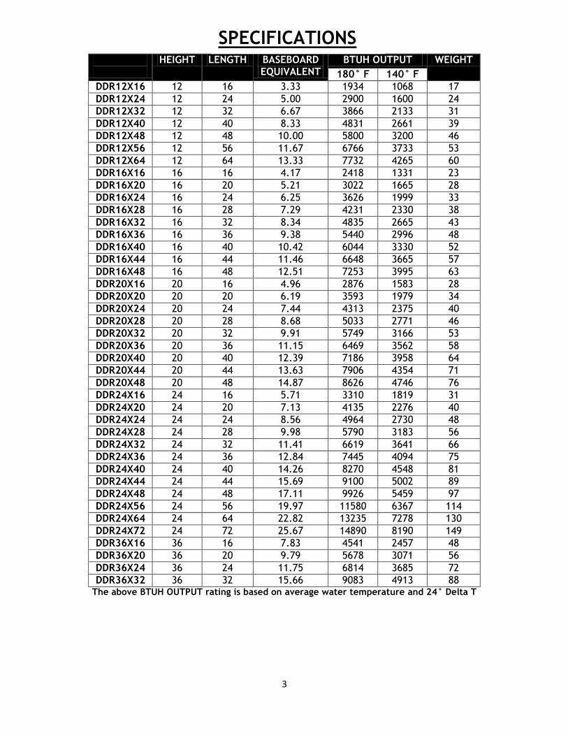
HEIGHT LENGTH BASEBOARD EQUIVALENT
BTUH OUTPUT WEIGHT
180° F 140° F
DDR12X16 12 16 3.33 1934 1068 17
DDR12X24 12 24 5.00 2900 1600 24
DDR12X32 12 32 6.67 3866 2133 31
DDR12X40 12 40 8.33 4831 2661 39
DDR12X48 12 48 10.00 5800 3200 46
DDR12X56 12 56 11.67 6766 3733 53
DDR12X64 12 64 13.33 7732 4265 60
DDR16X16 16 16 4.17 2418 1331 23
DDR16X20 16 20 5.21 3022 1665 28
DDR16X24 16 24 6.25 3626 1999 33
DDR16X28 16 28 7.29 4231 2330 38
DDR16X32 16 32 8.34 4835 2665 43
DDR16X36 16 36 9.38 5440 2996 48
DDR16X40 16 40 10.42 6044 3330 52
DDR16X44 16 44 11.46 6648 3665 57
DDR16X48 16 48 12.51 7253 3995 63
DDR20X16 20 16 4.96 2876 1583 28
DDR20X20 20 20 6.19 3593 1979 34
DDR20X24 20 24 7.44 4313 2375 40
DDR20X28 20 28 8.68 5033 2771 46
DDR20X32 20 32 9.91 5749 3166 53
DDR20X36 20 36 11.15 6469 3562 58
DDR20X40 20 40 12.39 7186 3958 64
DDR20X44 20 44 13.63 7906 4354 71
DDR20X48 20 48 14.87 8626 4746 76
DDR24X16 24 16 5.71 3310 1819 31
DDR24X20 24 20 7.13 4135 2276 40
DDR24X24 24 24 8.56 4964 2730 48
DDR24X28 24 28 9.98 5790 3183 56
DDR24X32 24 32 11.41 6619 3641 66
DDR24X36 24 36 12.84 7445 4094 75
DDR24X40 24 40 14.26 8270 4548 81
DDR24X44 24 44 15.69 9100 5002 89
DDR24X48 24 48 17.11 9926 5459 97
DDR24X56 24 56 19.97 11580 6367 114
DDR24X64 24 64 22.82 13235 7278 130
DDR24X72 24 72 25.67 14890 8190 149
DDR36X16 36 16 7.83 4541 2457 48
DDR36X20 36 20 9.79 5678 3071 56
DDR36X24 36 24 11.75 6814 3685 72
DDR36X32 36 32 15.66 9083 4913 88 The above BTUH OUTPUT rating is based on average water temperature and 24° Delta T
SPECIFICATIONS

4
If the heating system contains antifreeze, the proper pH must be maintained. High acidity will damage the radiator
and void the manufacturer’s warranty.
FITTINGS AND ACCESSORIES
ITEM # DESCRIPTION
DDEVK12 12" Wall Bracket Set
DDEVK16 16" Wall Bracket Set
DDEVK20 20" Wall Bracket Set
DDEVK24 24" Wall Bracket Set
DDEVK36 36" Wall Bracket Set
DDA318 Dual Pipe Escutcheon
DD39438* 3/8" Pex Tubing Adapter
DD39412* 1/2" Pex Tubing Adapter
DD39458* 5/8" Pex Tubing Adapter
DDA43112C* 1/2" Copper Pipe Adapter
DDA554 3/4"EK x 1/2" Reducer
DDV71110 Angle Isolation Valve w/By-Pass
DDV72110 Angle Isolation Valve
DDV71510 Straight Isolation Valve w/By-Pass
DDV72510 Straight Isolation Valve
DDA4040 Thermostatic Operator
DD8W White 8" Radsnap Pipe Cover
DD8C Chrome 8" Radsnap Pipe Cover
*Tube and pipe adaptors are sold individually.
WATER CONTENT
HEIGHT (GALS./Linear Ft.)
12” .35
16” .41
20” .47
24” .54
36” .73

TAPPING IDENTIFICATION
AIR VENT
DRAIN
THERMOSTATIC VALVE
DRAIN
SUPPLY AND RETURN
As indicated in the Data Table, Decoro Design steel panel radiators are double panel and available in five
different heights; 12”, 16”, 20”, 24” and 36”. Each size includes multiple lengths and heat outputs.
Radiators have a light eggshell white epoxy powder coated finish which, if desired, can be repainted by an
automobile refinishing professional to a color of your choice.
Each radiator is manufactured with six ½” BSP threaded connections, as shown in the illustration above,
one of which has a factory installed integral thermostatic valve/adjustable flow-setter, another, a manual
air vent, two with drain plugs and a bottom supply and return connection. Many different piping
configurations are possible, examples of which will be shown later in this manual.
Each radiator comes standard with two ¾” male EK x ½” male BSP O-Ring adapters, Decoro
Design Snap-Grip mounting brackets and a 10 YEAR warranty from the date of installation.
Warranty protects the original purchaser from manufacturing defects resulting from faulty materials
and/or factory workmanship, and applies to the product only.
6
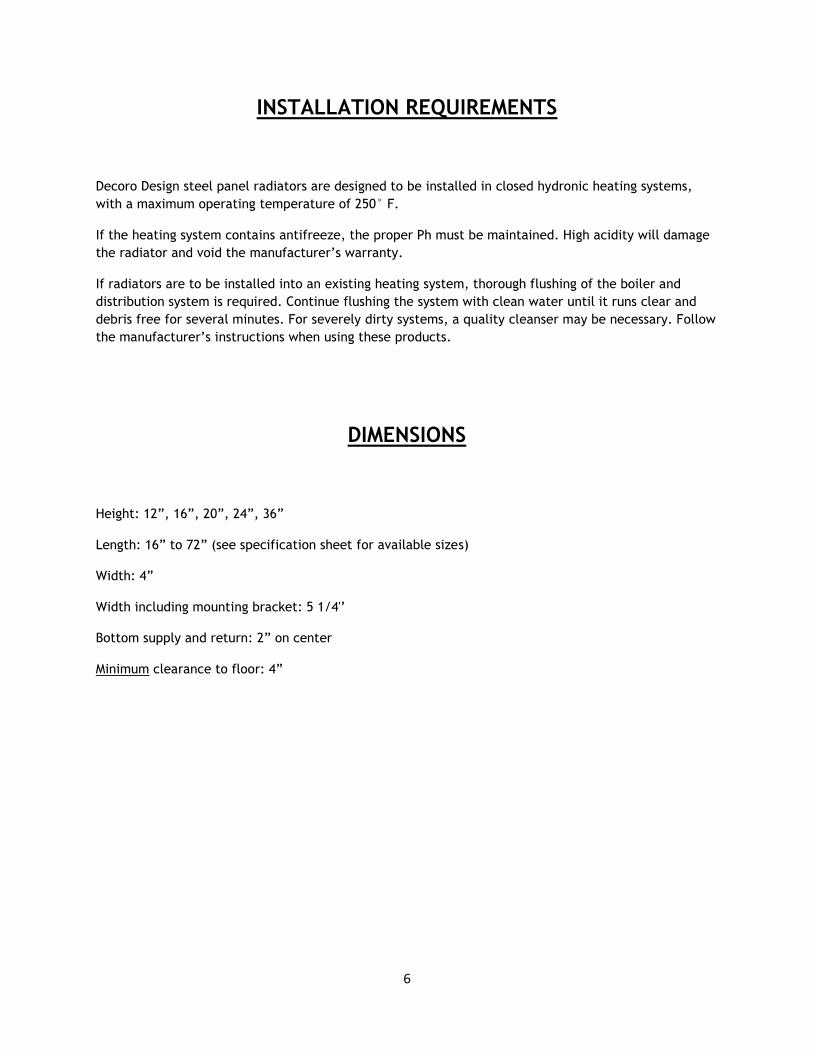
INSTALLATION REQUIREMENTS
Decoro Design steel panel radiators are designed to be installed in closed hydronic heating systems,
with a maximum operating temperature of 250° F.
If the heating system contains antifreeze, the proper Ph must be maintained. High acidity will damage
the radiator and void the manufacturer’s warranty.
If radiators are to be installed into an existing heating system, thorough flushing of the boiler and
distribution system is required. Continue flushing the system with clean water until it runs clear and
debris free for several minutes. For severely dirty systems, a quality cleanser may be necessary. Follow
the manufacturer’s instructions when using these products.
DIMENSIONS
Height: 12”, 16”, 20”, 24”, 36”
Length: 16” to 72” (see specification sheet for available sizes)
Width: 4”
Width including mounting bracket: 5 1/4'’
Bottom supply and return: 2” on center
Minimum clearance to floor: 4”

7
REDUCED AVERAGE WATER TEMPERATURE BTUH OUTPUTS
The above BTUH OUTPUT rating is based on average water temperature and a 24° F Delta T

8
SIZING
If unfamiliar with heating system design using steel panel radiators, please consult a qualified
distributor for guidance before proceeding.
1. An accurate heat loss must be performed to determine the load of the space(s) to be heated.
2. Based on a predetermined design water supply temperature, choose a radiator from the
specification chart(s) that most closely matches the heat loss of the space in which it is to be
installed. If a single radiator does not have enough capacity, divide the load evenly into two or
three radiators. Standard ratings are based on 68°F EAT, the average water temperature and a
24°F water Delta T across the radiator.
3. Radiators preferably should be mounted on an outside wall.
4. Determine if the wall chosen is large enough to accommodate the radiator. If not, multiple
radiators may be required.
5. Radiators must be mounted a minimum of 4” above the floor. If straight valves are to be
incorporated, additional floor clearance should be considered to ease the installation of the
tubing/pipes onto the radiator.
FLOW RATE
Flow rates for a Decoro Design steel panel radiator system are based on the calculated heat loss of
each heating zone. Using the calculated heat loss, determine the Btu load of each individual zone. The
following formula will be used to calculate the flow rate from the Btu load of the individual zones. The
following information is provided as informational only; system design should be conducted by a
qualified individual with panel radiator experience.
Flow Rate (GPM) = Heat Loss (Btu/h) / 500 x Delta T (F)*
Delta T is the temperature difference between the supply and return of the radiators in each zone.
Standard output ratings are based on a 24 degree Delta T (Temperature Drop) between the supply and
return of each panel radiator.
The following table provides several divisors for the above formula to make calculations quicker and
easier.
Delta T (F) Divisor
10 5,000
15 7,500
20 10,000
24* 12,000
25 12,500
30 15,000
35 17,500
* Standard Rating Application
9
FLOW RATE (Contd.)
Flow Rate (GPM) = Heat Loss (Btu/h) / Divisor (above chart)
Example:
Calculated Heat Loss of 23,500 Btu/h
24 Degree Delta T
Flow Rate (GPM) = 23,500 / 24 = 12,000 (above chart)
GPM = 23,500 / 12,000
GPM = 1.96
Series Piping of panel radiators is not a preferred method of installation due to the potential of
extreme temperature drops across the entire piping circuit. Very careful consideration of system design
is required before proceeding. Please consult a qualified distributor
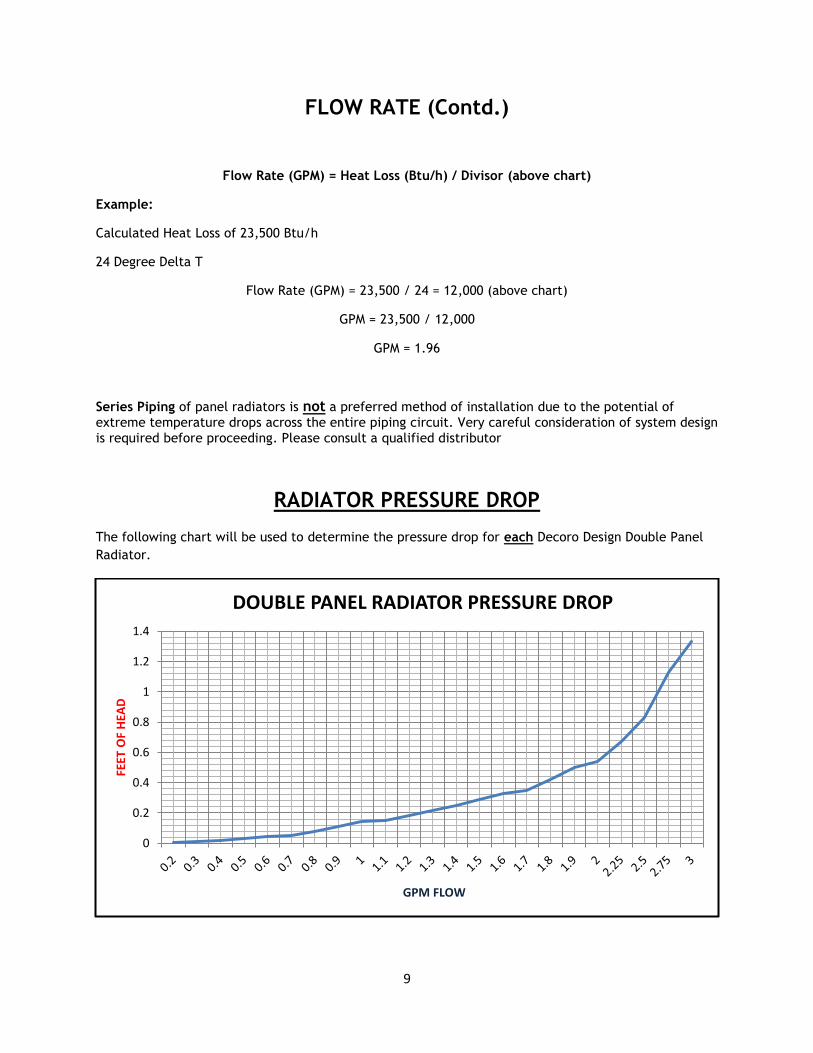
RADIATOR PRESSURE DROP
The following chart will be used to determine the pressure drop for each Decoro Design Double Panel
Radiator.
0
0.2
0.4
0.6
0.8
1
1.2
1.4
FEET
OF
HEA
D
GPM FLOW
DOUBLE PANEL RADIATOR PRESSURE DROP
10
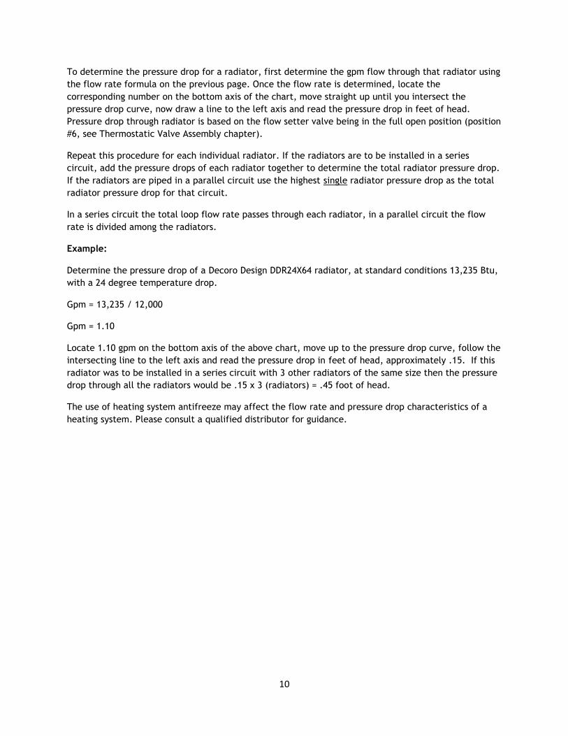
To determine the pressure drop for a radiator, first determine the gpm flow through that radiator using
the flow rate formula on the previous page. Once the flow rate is determined, locate the
corresponding number on the bottom axis of the chart, move straight up until you intersect the
pressure drop curve, now draw a line to the left axis and read the pressure drop in feet of head.
Pressure drop through radiator is based on the flow setter valve being in the full open position (position
#6, see Thermostatic Valve Assembly chapter).
Repeat this procedure for each individual radiator. If the radiators are to be installed in a series
circuit, add the pressure drops of each radiator together to determine the total radiator pressure drop.
If the radiators are piped in a parallel circuit use the highest single radiator pressure drop as the total
radiator pressure drop for that circuit.
In a series circuit the total loop flow rate passes through each radiator, in a parallel circuit the flow
rate is divided among the radiators.
Example:
Determine the pressure drop of a Decoro Design DDR24X64 radiator, at standard conditions 13,235 Btu,
with a 24 degree temperature drop.
Gpm = 13,235 / 12,000
Gpm = 1.10
Locate 1.10 gpm on the bottom axis of the above chart, move up to the pressure drop curve, follow the
intersecting line to the left axis and read the pressure drop in feet of head, approximately .15. If this
radiator was to be installed in a series circuit with 3 other radiators of the same size then the pressure
drop through all the radiators would be .15 x 3 (radiators) = .45 foot of head.
The use of heating system antifreeze may affect the flow rate and pressure drop characteristics of a
heating system. Please consult a qualified distributor for guidance.

11
“H” VALVE RADIATOR VALVE PRESSURE DROP
The following chart will be used to determine the pressure drop through all four types of Decoro Design
radiator valves.
Determining the pressure drop for the radiator valve is the same procedure used for the radiators on
the previous page. Find the calculated flow rate in Gpm on the bottom axis of the chart, move straight
up until you intersect the curve then draw a line to the left axis and read the pressure drop in feet of
head.
Repeat this procedure for each individual radiator. If the radiators are to be installed in a series
circuit, add the pressure drop of each valve in the circuit together to determine the total valve
pressure drop. If the radiators are to be piped in parallel the valve with the highest pressure drop will
determine the total valve pressure drop for that circuit.
In a series circuit the total loop flow rate passes through all the valves, in a parallel circuit the flow
rate is divided among the valves.
Example:
Using the example from the previous page; a DDR24X64 radiator emitting 13,235 Btu @ 1.1 Gpm flow
Find 1.1 Gpm on the bottom axis of the chart, move straight up until you intersect the curve, now
follow the horizontal line to the left axis and read the pressure drop for this valve in feet of head,
approximately 1.0’.
If there were 3 of these radiators installed in a series circuit the total valve pressure drop would be 3
feet of head (3 x 1.0’ = 3’). In a parallel circuit, with the same 3 radiators, the total valve pressure
drop for the circuit would be 1.0’, the largest individual valve pressure drop in the parallel circuit.
0123456789
1011121314151617
0.3
0.4
0.5
0.6
0.7
0.8
0.9 1
1.1
1.2
1.3
1.4
1.5
1.6
1.7
1.8
1.9 2
2.2
5
2.5
2.7
5 3
3.2
5
3.5
3.7
5 4
FEET
OF
HEA
D
GPM FLOW
RADIATOR VALVE PRESSURE DROP

12
TOTAL PRESSURE DROP
Total Piping Circuit Pressure Drop
The total circuit pressure drop is calculated by adding together the total radiator pressure drop, total
H-valve pressure drop, boiler pressure drop, and the supply and return piping pressure drop (including
all devices installed within the piping. (Flowcheck, airscoop, valves etc.).
Circulator Sizing
Circulator size is determined by two criteria; flow rate in gpm and pressure drop in foot of head. After
these two items have been calculated for a particular piping circuit, a circulator can be chosen using
the manufacturer’s performance curve.
Example;
One Decoro Design DDR24X72 panel radiators, 14,890 Btus, installed in a piping circuit designed for a 24 degree temperature drop across the radiator.
Flow rate = 1 x 14,890 / 12,000
Flow rate = 1.24 gpm
Radiator Pressure drop = .19 foot of head (from radiator pressure drop chart)
H-valve pressure drop = 1.5 foot of head (from H valve pressure drop chart)
Boiler pressure drop = 1 foot of head (from manufacturers’ information)
Supply & return pressure drop = 4.5 foot of head (calculated)
Total Circuit Pressure Drop = 7.19 foot of head
1.24 gpm @ 7.19 foot of head
Using the manufacturer’s performance curves, choose a circulator that meets or slightly exceeds the
circuits’ requirements, see example below.
0
5
10
15
1 2 3 4 5 6 7 8 9 10 11 12 13 14 15 16 17 18
Tota
l He
ad -
Fe
et
GPM
Circulator Curve

13
RADIATOR ROUGH-IN
Dimensions
Radiators should be placed on an outside wall, below a window if possible. Check the installation
location and determine if adequate space is available to accommodate the panel size chosen.
Decoro Design recommends the use of the bottom supply and return connections. These connections are located near the end of the radiator. The return connection is 1 3/8” from the end and the supply is 2” further in towards the radiator center. This connection location will accept any one of the four optional H-Valves.
Decoro Design panel radiators are reversible, dependent upon which side is facing the rooms’ interior the supply and return connections may be located either on the left or right hand side. Be sure the
proper connection location is selected before drilling piping holes.
See the above figure for additional dimensions and rough-in information.
The optional side connections may be used in lieu of the preferred bottom connections. Care must be taken when using these connections. In some cases the integral thermostatic/flow-setter valve will be by-passed causing continued, uncontrolled heating of the radiator. The plugs removed from the side connections must be installed in the unused bottom connections before filling the system with water.
Decoro Design valves are not compatible with the side connections.
See the ‘Piping Options’ section of this manual for more information.

14
BRACKET AND RADIATOR MOUNTING
Decoro Design Snap-Grip mounting brackets must be securely fastened to the wall. Frame type
construction requires the brackets to be fastened to the wall studs, preferably towards the ends of the
radiator. With 16” long radiator, if at least bracket cannot be secured to a wall stud, use 3/8”
(minimum) hollow wall toggle bolt fasteners. Additional bracket sets are available if required.
Each pair of brackets includes; 2 mounting bolts and plastic masonry anchors; do not use these anchors
on frame type construction (figure 1).
Install the brackets, aligning the bottom with the desired height of the radiator bottom; a minimum of
4” is required (additional space should be considered when incorporating straight valves to ease
pipe/tubing installation). Plumb the brackets against the wall and mark the screw locations. Drill pilot
holes, install the screws (don’t tighten to the wall), hang the brackets from the screws and tighten
completely.
Extend the top clamp by pulling the nylon thumb retainer towards you approximately ¼” of an inch
while lifting up on the top clamp, repeat for all brackets. Lift the radiator and angle the bottom
towards the wall, set the inside water panel into the nylon bottom bracket (figure 2). Tilt the top of
the radiator towards the wall, when parallel with the wall; push the top clamp down onto the top rear
of the radiator until a click is heard (figure 3). An adjustment screw is installed on the top of the top
clamp; this permits minor adjustments to the clamp location if necessary (figure 3).
Figure 1
Figure 2 Figure 3 Figure 4

15
TUBING AND PIPE ADAPTORS
Decoro Design panel radiators may be connected directly to the system piping using the available pex
tubing or copper pipe adapters. Isolation and by-pass valves are also available and are installed
between the radiator and tubing/pipe adapters.
Pex Tubing Adapter Assembly
Pipe thread sealant is not required. Insert the DDA554 reducers into the supply and return connections
of the radiator and tighten with a 12mm Allen wrench. Choose the proper size pex tubing adapter.
Slide the nut onto the tubing followed by the compression ring, and then insert the o-ring fitting into
the end of the tubing. Firmly insert the tubing into the DDA554 reducer until it bottoms out and hold it
there. Slide the nut and compression ring onto the DDA554 reducer and tighten. Do not overtighten.
DD39438 – 3/8” Pex Adapter
DD39412 – ½” Pex Adapter
DD39458 – 5/8” Pex Adapter
Pex Tubing
Radiator Bottom
DDV71110 Angle Valve w/By-Pass
DDV72110 Angle Valve
DDV71510 Straight Valve w/ By-Pass
DDV72510 Straight Valve
DDA554 ¾” EK x ½” Reducer
DD39438 – 3/8” Pex Adapter
DD39412 – ½” Pex Adapter
DD39458 – 5/8” Pex Adapter

16
COPPER PIPE ADAPTER ASSEMBLY
Pipe thread sealant is not required. Insert the DDA554 reducers into the supply and return connections
of the radiator and tighten with a 12mm allen wrench. Slide the DDA43112C-1/2” copper adapter (one
piece) onto the copper pipe. Insert the copper pipe into the reducer and hold it. Slide the copper
adapter up the pipe and attach it to the DDAA554 reducer and tighten. Do not overtighten.
Installation assembly using valves is the same as described above. The only difference is the addition of
one of the valves between the DDA554 reducer and tubing or pipe adapter.
Radiator Bottom
DDA554 ¾” x ½” Reducer
DDV71110 Angle Valve w/By-Pass
DDV72110 Angle Valve
DDV71510 Straight Valve w/By-Pass
DDV72510 Straight Valve
DDA43112C Pipe Adapter
17
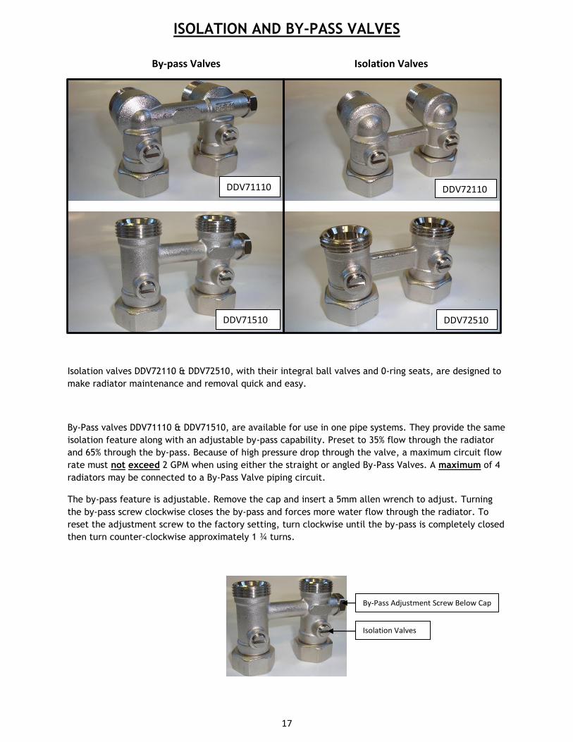
ISOLATION AND BY-PASS VALVES
Isolation valves DDV72110 & DDV72510, with their integral ball valves and 0-ring seats, are designed to
make radiator maintenance and removal quick and easy.
By-Pass valves DDV71110 & DDV71510, are available for use in one pipe systems. They provide the same
isolation feature along with an adjustable by-pass capability. Preset to 35% flow through the radiator
and 65% through the by-pass. Because of high pressure drop through the valve, a maximum circuit flow
rate must not exceed 2 GPM when using either the straight or angled By-Pass Valves. A maximum of 4
radiators may be connected to a By-Pass Valve piping circuit.
The by-pass feature is adjustable. Remove the cap and insert a 5mm allen wrench to adjust. Turning
the by-pass screw clockwise closes the by-pass and forces more water flow through the radiator. To
reset the adjustment screw to the factory setting, turn clockwise until the by-pass is completely closed
then turn counter-clockwise approximately 1 ¾ turns.
DDV71110 DDV72110
DDV71510
0
DDV72510
By-Pass Adjustment Screw Below Cap
Isolation Valves
By-pass Valves Isolation Valves

18
INTEGRAL THERMOSTATIC VALVE AND FLOW SETTER
ASSEMBLY
Decoro Design panel radiators have integral thermostatic and flow setter valves installed as standard
equipment, thermostatic operators are optional.
Flow Setter is factory set to “6”.
Flow Setter is adjusted by removing the white factory installed white cap (turn
counterclockwise) and then turning the inner gland (picture above) to the
corresponding number. When finished, replace the white cap but do not
tighten. If the cap is tightened water flow through the valve will be further
impeded.
As the flow setter valve opening is reduced the pressure drop (resistance)
through the radiator will increase. Considering the additional pressure,
circulator performance may need to be re-assessed.
Optional Thermostatic Operator Settings
Install the optional thermostatic operator by first removing the factory installed white cap covering the
thermostatic valve (turn counterclockwise). Thermostatic valve should be set to “6”. Set the
thermostatic operator to # 5 and then screw onto the valve and tighten. Adjust the operator to the
desired room temperature using the reference table below.
Flow Setter
Number Percentage
Open
1 10
2 20
3 30
4 40
5 50
6 100
Thermostatic Operator
Number Approximate
Room Temperature
Snowflake 43.7 F
1 51.8 F
2 60.8 F
3 68.0 F
4 75.2 F
5 81.5 F
Integral Valve Assembly
Flow Setter Adjustment (numbered)
30 MM Thread Accepts Optional
Thermostatic Operator

19
WATER FLOW
Piping schematics provided on the following pages are informational only and just a small
sampling of possible piping arrangements. Sound engineering practices must be adhered
to when designing any steel panel radiator heating system.
Series Circuit (Maximum Circuit Flow Rate Is 1.5 GPM, and/or 3 Radiators). This is not a
preferred method of installation because of the potential of very large temperature drops across the
piping circuit. Please consult a qualified individual before proceeding.
20
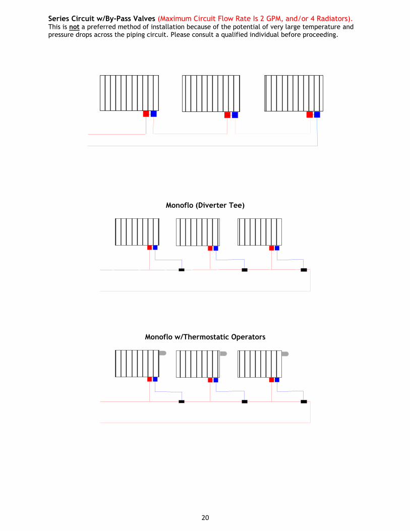
Series Circuit w/By-Pass Valves (Maximum Circuit Flow Rate Is 2 GPM, and/or 4 Radiators). This is not a preferred method of installation because of the potential of very large temperature and pressure drops across the piping circuit. Please consult a qualified individual before proceeding.
Monoflo (Diverter Tee)
Monoflo w/Thermostatic Operators
21
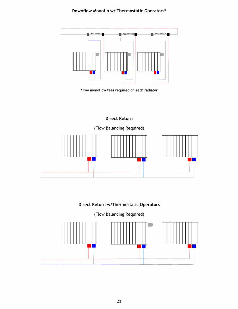
Downflow Monoflo w/ Thermostatic Operators*
1 Foot Minimum 1 Foot Minimum 1 Foot Minimum
*Two monoflow tees required on each radiator
Direct Return
(Flow Balancing Required)
Direct Return w/Thermostatic Operators
(Flow Balancing Required)

22
Reverse Return With or Without Thermostatic Operators
Homerun
Homerun with Thermostatic Operators and By-Pass Valve

23
Homerun with Electric Zone Valve and By-Pass Valve
Homerun with Thermostatic Operators and Variable Speed Delta T Circulator
24
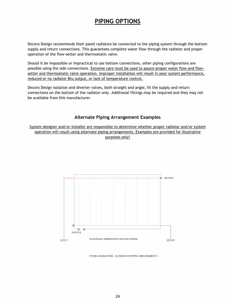
PIPING OPTIONS
Decoro Design recommends their panel radiators be connected to the piping system through the bottom
supply and return connections. This guarantees complete water flow through the radiator and proper
operation of the flow-setter and thermostatic valve.
Should it be impossible or impractical to use bottom connections, other piping configurations are
possible using the side connections. Extreme care must be used to assure proper water flow and flow-
setter and thermostatic valve operation. Improper installation will result in poor system performance,
reduced or no radiator Btu output, or lack of temperature control.
Decoro Design isolation and diverter valves, both straight and angle, fit the supply and return
connections on the bottom of the radiator only. Additional fittings may be required and they may not
be available from this manufacturer.
Alternate Piping Arrangement Examples
System designer and/or installer are responsible to determine whether proper radiator and/or system
operation will result using alternate piping arrangements. Examples are provided for illustrative
purposes only!
AIR VENT
PLUGS (3)
NO INTEGRAL THERMOSTATIC OR FLOW CONTROL
PENSOTTI PANEL RADIATORS - ALTERNATE PIPING ARRANGMENT 1
SUPPLY RETURN

25
AIR VENT
PLUGS (2)
NO INTEGRAL THERMOSTATIC OR FLOW CONTROL
PENSOTTI PANEL RADIATORS - ALTERNATE PIPING ARRANGEMENT 2
PLUG
RETURN SUPPLY
AIR VENT
PLUGS (2)
NO INTEGRAL THERMOSTATIC OR FLOW CONTROL
PENSOTTI PANEL RADIATORS - ALTERNATE PIPING ARRANGEMENT 3
PLUG
RETURN SUPPLY
AIR VENT
PLUGS (2)
NO INTEGRAL THERMOSTATIC OR FLOW CONTROLSUPPLY RETURN
THERMOSTATICVALVE
PENSOTTI PANEL RADIATORS - ALTERNATE PIPING ARRANGEMENT 4
NOT RECOMMENDED
AIR VENT
PLUGS (2)
SUPPLYRETURN
THERMOSTATICVALVE
FULL THERMOSTATIC AND FLOW CONTROL
PENSOTTI PANEL RADIATORS - ALTERNATE PIPING ARRANGEMENT 4

26
AIR VENT
PLUG
SUPPLYRETURN
THERMOSTATICVALVE
FULL THERMOSTATIC AND FLOW CONTROL
PENSOTTI PANEL RADIATORS - ALTERNATE PIPING ARRANGEMENT 5
PLUG
AIR VENT
PLUGS (2)
SUPPLY RETURNNO INTEGRAL THERMOSTATIC OR FLOW CONTROL
PENSOTTI PANEL RADIATORS - ALTERNATE PIPING ARRANGEMENT 6
PLUG
AIR VENT
PLUGS (3)
SUPPLYRETURN
NO INTEGRAL THERMOSTATIC OR FLOW CONTROL
PENSOTTI PANEL RADIATORS - ALTERNATE PIPING ARRANGEMENT 7
PLUGS (3)
NO INTEGRAL THERMOSTATIC OR FLOW CONTROLSUPPLY RETURN
PENSOTTI PANEL RADIATORS - ALTERNATE PIPING ARRANGEMENT 4
NOT RECOMMENDED
NO AIR VENT
PLUG

27
PLUGS (2)
NO INTEGRAL THERMOSTATIC OR FLOW CONTROLSUPPLY RETURN
PENSOTTI PANEL RADIATORS - ALTERNATE PIPING ARRANGEMENT 4
NOT RECOMMENDED
PLUG
AIR VENT
PLUGS (2)
NO INTEGRAL THERMOSTATIC OR FLOW CONTROLSUPPLY RETURN
PENSOTTI PANEL RADIATORS - ALTERNATE PIPING ARRANGEMENT 4
NOT RECOMMENDED
PLUG
AIR VENT
PLUGS (3)
NO INTEGRAL THERMOSTATIC OR FLOW CONTROLSUPPLY RETURN
PENSOTTI PANEL RADIATORS - ALTERNATE PIPING ARRANGEMENT 4
NOT RECOMMENDED
AIR VENT

28
FOLLOWING PAGES INTENTIONALLY LEFT BLANK

29