panel-mounting thermostats em...
TRANSCRIPT

Panel-mountingThermostats
EM Series
B 60.2021.0Operating Instructions
11.06/00073772

Please read these Operating Instructions before commissioning the instrument. Keep themanual in a place that is accessible to all users at all times. Please assist us to improvethese operating instructions, where necessary. Your comments will be appreciated.
Phone +49 661 6003-0Fax +49 661 6003-607
All necessary settings and possible adjustments inside the instrument are described inthese operating instructions. If any problems should still arise during start-up, you areasked not to carry out any unauthorized manipulations on the unit. You could endangeryour rights under the instrument warranty! Please contact the nearest subsidiary or thehead office in such a case.

Contents
1 Introduction .................................................................................. 51.1 Typographical conventions ......................................................................... 51.1.1 Warning signs ................................................................................................. 51.1.2 Note signs ...................................................................................................... 5
1.2 Application .................................................................................................... 6
1.3 Marking ......................................................................................................... 6
1.4 Safety notes .................................................................................................. 7
2 Instrument identification ............................................................. 82.1 Nameplate ..................................................................................................... 8
2.2 Type designation .......................................................................................... 9
3 Mounting .................................................................................... 103.1 Dimensions ................................................................................................. 10
3.2 Fixing the panel-mounting thermostat ..................................................... 123.2.1 Mounting the switch head ............................................................................ 12
3.3 Capillary / temperature probe / pocket .................................................... 143.3.1 General ......................................................................................................... 143.3.2 Approved probes or pockets ....................................................................... 15
3.4 Permissible loading on the pocket ........................................................... 183.4.1 Pockets U, US, E and ES ............................................................................. 18
4 Installation .................................................................................. 224.1 Regulations and notes ............................................................................... 22
4.2 Electrical connection ................................................................................. 22
4.3 Connection diagrams ................................................................................. 24
5 Settings ....................................................................................... 255.1 Resetting the operating (TB)
or protection temperature limiter (STB) ................................................... 25
5.2 Setpoint adjustment ................................................................................... 26
5.3 Self-monitoring on the STB and STW (STB) ............................................ 26
5.4 Use of the STW (STB) as STB .................................................................... 26
6 Instrument description .............................................................. 276.1 Technical data ............................................................................................. 27


5
1 Introduction
1.1 Typographical conventions
1.1.1 Warning signs
1.1.2 Note signs
abc1 Footnote
Footnotes are remarks that refer to specific points in the text. Footnotesconsist of two parts:
A marker in the text, and the footnote text.
The markers in the text are arranged as continuous superscript numbers.
The footnote text (in smaller typeface) is placed at the bottom of the page andstarts with a superscript number.
✱ Action instruction
This symbol indicates that an action to be performed is described.
The individual steps are marked by this asterisk, e.g.
✱ Open housing
V Danger
This symbol is used when there may be danger to personnel if theinstructions are ignored or not followed correctly!
A Caution
This symbol is used when there may be damage to equipment if theinstructions are ignored or not followed correctly!
H Note
This symbol is used when your special attention is drawn to a remark.
v Reference
This symbol refers to further information in other chapters or sections.

1 Introduction
6
1.2 Application
Thermostats control and monitor thermal processes.
Panel-mounting thermostats operate on the principle of liquid or gasexpansion. A microswitch serves as the electrical switching device.
EM series instruments are available as temperature controllers TR, operatingtemperature limiters TW and TB as well as protection temperature limitersSTW and STB.In the event of a fault, the STB sets the system being monitored to a safeoperational state.
Versions to: DIN 3440 and EN 14597 (draft)
TR Temperature controllerTW Operating temperature limiterTB Operating temperature limiterSTW(STB) Protection temperature limiterSTB Protection temperature limiter
Type examination as per:
- DIN 3440
- Pressure Equipment Directive 97/23/EC(Types EM-20, EM-30, EM-40, EM-50 only)
- VDE 0631 (permissible ambient temperature up to +80°C only)
- UL (setpoints or limit values up to +300°C only)
- CSA (Types EM-1, EM-2, EM-4, EM-50 only)
You will find the Declarations of Conformity at:
www.jumo.net ➯ Products ➯ Thermostats ➯ Data Sheet 60.2021
or ask for them to be sent.
1.3 Marking
Depending on the version:
(see nameplate for details)
A Cutting through or kinking the capillary of the panel-mounting thermostat, EM series, will lead to permanent instrument failure!!

7
1 Introduction
1.4 Safety notes
Physical and toxicological properties of the expansion fluid that may escape in the event of a system fracture.
1 At present, there is no restrictive statement from the health authorities concerning any danger to health over short periods and at low concentration, e.g. after a fracture of the measuring system.
H Filling liquid may escape in the event of a measuring system fracture.At present, any health risks can be excluded.
Control rangewith
end of scale°C
Dangerous reactions
Fire andexplosion hazard
Watercontamination
Toxicological data
Ignitiontemperature
°C
Explosion limit
% v/virritant
dangerto health
toxic
< +200 no +355 0.6 - 8 yes yes 1 no
� +200 ≤ +350 no +490 - - yes yes 1 no
> +350 ≤ +500 no no no no no no no

8
2 Instrument identification
2.1 Nameplate
( 1 ) Type code (see type designation)
( 2 ) Control range
( 3 ) Contact rating
( 4 ) Approval mark
( 1 )
( 2 )
( 3 )
( 4 )

9
2 Instrument identification
2.2 Type designation
Typedesignation
EM - .. - .. / .. Panel-mounting thermostat with one microswitch
EMF - .... - .. / .. Panel-mounting thermostat with 2, 3 or 4 microswitches
Standard connection A (plain cylindrical probe)
- 1... Temperature controller TR with changeover contact
- 2... Operating temperature limiter TW with changeover contact
- 3... Operating temperature limiter TW with changeover contact; factory-set switching point
- 4... Operating temperature limiter TB withn.c. (break) contact and lock-out;factory-set switching point
- 5... Operating temperature limiter TB withn.c. (break) contact and lock-out
- 20 Protection temperature limiter STW(STB) with changeover contact
- 30 Protection temperature limiter STW(STB) with changeover contact, factory-set switching point
- 40 Protection temperature limiter STB withn.c. (break) contact and lock-out,factory-set switching point
- 50 Protection temperature limiter STB withn.c. (break) contact and lock-out
- .... - TK Temperature compensation at switch head
- .... - .. / au Snap-action switch contacts gold-plated
- .... - .. / U Microswitch with n.c. (break) contact, lock-out and additional signal contact (TB and STB only)

10
3 Mounting
3.1 DimensionsEM-1
EMF-13
omitted withcodes 2, 3, 4, 5
Reset button(with codes 4 and 5 only)
Faston connectorA 6.3 x 0.8 to DIN 46 244
Rear view
Wiedereinschaltknopfnur bei Kurzzeichen 4, 5, 40 u. 50
entfällt beiKurzeichen 2, 3, 4, 5, 20, 30, 40, 50
omitted withcodes 2, 3, 4, 5, 20, 30,
40, 50
Reset button(with codes 4, 5, 40 and 50 only)
Faston connectorA 6.3 x 0.8 to DIN 46 244
Rear view

11
3 Mounting
EMF-133
EMF-1333
omitted withcodes 2, 3, 4, 5
Reset button(with codes 4 and 5 only)
Faston connectorA 6.3 x 0.8 to DIN 46 244
Rear view
omitted withcodes 2, 3, 4, 5
Reset button(with codes 4 and 5 only)
Faston connectorA 6.3 x 0.8 to DIN 46 244
Rear view
3 Mounting
12
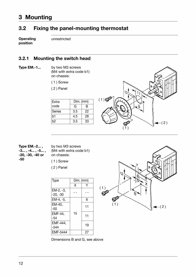
3.2 Fixing the panel-mounting thermostat
Operating position
unrestricted
3.2.1 Mounting the switch head
Type EM.-1... by two M3 screws(M4 with extra code b1)on chassis:
( 1 ) Screw
( 2 ) Panel
Type EM.-2... ,-3... , -4... , -5... , -20, -30, -40 or-50
by two M3 screws(M4 with extra code b1)on chassis:
( 1 ) Screw
( 2 ) Panel
Dimensions B and G, see above
Extracode
Dim. (mm)G B
Series 3.5 22b1 4.5 28b2 3.5 33
( 1 )
( 1 )( 2 )
Type Dim. (mm)X Y
EM-2, -3, -20, -30
- - - -
EM-4, -5,
15
6EM-40,-50
11
EMF-44, -54
11
EMF-444, -544
19
EMF-5444 27
( 1 )
( 1 )( 2 )

13
3 Mounting
Type EM.-4, -5, -40 or -50central fixing(extra code b7)
( 1 ) Panel
( 2 ) Fixing nutM10 x 1 (13 a/f)
(3) Cap nut M10 x 1(10 a/f)
(4) Reset button
Type Dim. (mm)X Y
EM-4, -516
6EM-40,-50,
11
( 1 )( 2 )
( 3 )
( 4 )

3 Mounting
14
3.3 Capillary / temperature probe / pocket
3.3.1 General
A Cutting through or kinking the capillary of the panel-mounting thermostat willlead to permanent instrument failure!
Minimum permissible bending radius of the capillary is 5 mm.
The temperature probe must be mounted in a JUMO pocket, otherwise theapproval of the panel-mounting thermostat becomes invalid.
The temperature probe must be completely immersed in the medium to bemeasured. The temperature probe or protection tube must not come intocontact with the walls of the container or pipe.
To ensure their overall accuracy, the thermostats must only be used togetherwith the pockets supplied by the factory (diameter D = 8 or D = 10 mm).
Pockets with diameter D = 10 mm may only be fitted with probes withdiameter d = 8 mm.
Fitting several probes into a common pocket is permissible with 2 or 3cylindrical probes with diameter D = 6 mm and pockets 15 x 0.75 mm.When fitting 2 probes in a common pocket, the factory-supplied spring clipmust be fitted in the pocket.
For operation in air, probe mounting type “A” (without pocket) must be chosen.
In the case of pockets U, US, E, ES in materials St35.8 I / 16Mo3, thepermissible operating life at operating temperatures above +420°C is limitedto 200,000 hours. The requirements of TRD 508 must be observed foroperation in this range.
Immersion tube
Temperature probe

15
3 Mounting
3.3.2 Approved probes or pockets
FormsA and H
FormsD, B and C
A HPlain cylindrical probe Coiled probe
L
_15
Ød
d
D
~10
L110
L
D B C
Plain cylindrical probe, threaded connector brazed or welded to capillary
Probe mounting C with loose nipple, threaded at both ends
Plain cylindrical probe with shoulder and union nut, shoulder brazed or welded to capillary
SW
L
d
~15
G
L1
S
hex SW
L
d
~15
G
L1
S
hex
SW
L
d
~15
L1S
hex

3 Mounting
16
FormsU and US
FormsUH and UO
U USScrew-in pocket with screw-in spigot Form A to DIN 3852/2, with fixing screw
Weld-in pocket with fixing screw and clip
SW
S
G ½
14
Ø D
hex
27
S
ØD
Ø 25
Ø 8
Ø 12
Ø 30
UH UO
Screw-in pocket with fixing screw, for hemp sealing (no sealing shoulder) for temperatures up to 110°C
Screw-in pocket open at end, with fixing screw
SW
D
G
L1S
hex SW
d
S
L1
G
D
hex

17
3 Mounting
FormsE and ES
FormsQ and V
E ESScrew-in pocket secured with union nut, probe mounting C
Weld-in pocket with welding shoulder, pocket secured with union nut, probe mounting C
SW
D
L1
S
G
hexSW
D2
8Ø
12Ø
D
S
hex
Q V
Double thread for retrofitting on capillary. Max. probe temperature +200°C.Oil-resistant seal.
Sealing gland for retrofitting on capillary.Max. probe temperature +200°C.Oil-resistant seal.
Scheibe
Scheibe
Dichtung
SW
d
G
L1
Washer
Seal
Washer
hex
Scheibe
Scheibe
Dichtung
SW
Dichtung
d
G
L1
Washer
Seal
Washer
Seal
hex
3 Mounting
18
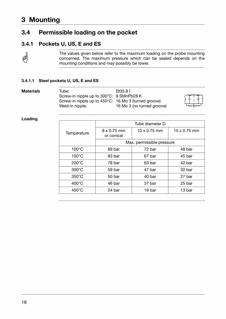
3.4 Permissible loading on the pocket
3.4.1 Pockets U, US, E and ES
3.4.1.1 Steel pockets U, US, E and ES
Materials Tube: St35.8 IScrew-in nipple up to 300°C: 9 SMnPb28 KScrew-in nipple up to 450°C: 16 Mo 3 (turned groove)Weld-in nipple: 16 Mo 3 (no turned groove)
Loading
A The values given below refer to the maximum loading on the probe mountingconcerned. The maximum pressure which can be sealed depends on themounting conditions and may possibly be lower.
Temperature
Tube diameter D
8 x 0.75 mmor conical
10 x 0.75 mm 15 x 0.75 mm
Max. permissible pressure
100°C 89 bar 72 bar 48 bar
150°C 83 bar 67 bar 45 bar
200°C 78 bar 63 bar 42 bar
300°C 59 bar 47 bar 32 bar
350°C 50 bar 40 bar 27 bar
400°C 46 bar 37 bar 25 bar
450°C 24 bar 19 bar 13 bar

19
3 Mounting
Permissibleincident flowvelocity
Permissible incident flow velocity (m/sec) at the maximum permissiblepressure loading and different immersion tube lengths “S”.
Permissible incident flow velocity (m/sec) at the maximum permissiblepressure loading and different immersion tube temperatures “t”.
Material: St35.8 ITemperature: +200°C
Thermal medium:airwater, oil
Tube diameter D: 08 mm10 mm
. . . . . . . . . . . . . . 15 mm
[m/sec]
Air
Water, oil
Immersion tube length (mm)
Material: St35.8 IImmersion tube length “s”: 200 mm
Thermal medium:airwater, oil
Tube diameter D: 08 mm10 mm
. . . . . . . . . . . . . . 15 mm
[m/sec]Air
Air
Air
Water, oil
Temperature °C

3 Mounting
20
3.4.1.2 Stainless steel pockets U, US, E and ES
Loading
3.4.1.3 Brass pockets U and E
Loading
3.4.1.4 Brass pocket UH
Loading
3.4.1.5 Probe mountings B, C and D
Material of tube and nipple: X 6 CrNiMoTl 17 122
Temperature
Tube diameter D
8 x 0.75 mmor conical
10 x 0.75 mm 15 x 0.75 mm
Max. permissible pressure
100°C 92 bar 74 bar 50 bar
150°C 88 bar 71 bar 48 bar
200°C 83 bar 67 bar 45 bar
300°C 72 bar 58 bar 39 bar
400°C 67 bar 54 bar 36 bar
Material of tube and nipple: CuZn
Temperature
Tube diameter D
8 x 0.75 mm 10 x 0.75 mm 15 x 0.75 mm
Max. permissible pressure
100°C 50 bar 40 bar 27 bar
150°C 48 bar 39 bar 26 bar
Material of tube and nipple: CuZn
Temperature Max. permissible pressure
110°C 16 bar
Nipple material CuZn 9 SMnPb.28 K X 6 CrNiMoTl 17 122
Temperature °C 200 300 400

21
3 Mounting
Probe material Ø mmThermostat action
TR, TW, TB STB, STW (STB)
Cu-DHP
4 6 bar
2 bar
5 5 bar
6 4 bar
7 3 bar
8 3 bar
9 3 bar
10 3 bar
St35 / 1.4571 4 - 10 10 bar 2 bar
A Forms A, H, UO, Q, V may only be used in unpressurized media.
H The temperature probe (2) must be immersed in the medium for its entirelength, otherwise there will be appreciable deviations from the switching point.
In the case of probe mountings U, US, UH and UO, the temperature probe issecured in the pocket by a clamping clip (1).
(1)
(2)

22
4 Installation
4.1 Regulations and notes
4.2 Electrical connection❏ Terminals and connections are suitable for internal conductors
❏ The connection is suitable for fixed wiring.
❏ Cable entry without strain relief
❏ The electrical connection must only be carried out by qualified personnel.
❏ The choice of cable, the installation and the electrical connection mustconform to the requirements of VDE 0100 “Regulations on the Installationof Power Circuits with Nominal Voltages below 1000 V” or the appropriatelocal regulations.
❏ If contact with live parts is possible while working on the instrument, it mustbe completely disconnected from the electrical supply.
❏ Earth the instrument at the PE terminal to the protective earth conductor.This cable must have at least the same cross-section as used for the supplycables. Earthing cables must be wired in a star configuration to a commonearth point that is connected to the protective earth conductor of theelectrical supply. Do not loop earthing cables, i.e. do not run them from oneinstrument to another.
❏ Apart from faulty installation, incorrect settings on the thermostat may alsoaffect the proper functioning of the subsequent process or lead to damage.Setting up must therefore be restricted to qualified personnel. Pleaseobserve the relevant safety regulations for such matters.
❏ The thermostat conforms to Protection Class I.
Capillary tube has no protective conductor function!
With respect to the probe and capillary, the user himself is responsible fortaking the necessary protective measures against electric shock.

23
4 Installation
Plug connection(standard)
( 1 ) = faston connector A 6.3 x 0.8 to DIN 46 244
Screwconnection(extra code X)
( 1 ) Receptacle 6.3 with connection screw, suitable for conductor cross-sections up to 2.5 mm2; attachment type X, no special tools
( 2 ) Terminal strip
( 1 )
2
1
4 Installation
24
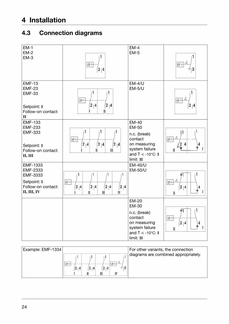
4.3 Connection diagrams
EM-1EM-2EM-3
EM-4EM-5
EMF-13EMF-23EMF-33
Setpoint: IFollow-on contact: II
EM-4/UEM-5/U
EMF-133EMF-233EMF-333
Setpoint: IFollow-on contact: II, III
EM-40EM-50
n.c. (break) contacton measuring system failure and T < -10°C: Ilimit: II
EMF-1333EMF-2333EMF-3333
Setpoint: IFollow-on contact:II, III, IV
EM-40/UEM-50/U
EM-20EM-30
n.c. (break) contacton measuring system failure and T < -10°C: Ilimit: II
Example: EMF-1334 For other variants, the connection diagrams are combined appropriately.

25
5 Settings
5.1 Resetting the operating (TB) or protection temperature limiter (STB)
EM-4EMF-4...EM-5EMF-5...EM-40EM-50with fixing bracket b1, b2, b3
After the temperature has dropped by about 10% of span below the set limit(critical temperature), the microswitch can be reset.
✱ Push the reset button using a small screwdriver
EM-4EMF-4...EM-5EMF-5...EM-40EM-50with centralfixing b7
✱ Unscrew cap
✱ Press reset button
✱ Screw cap back into position

5 Settings
26
5.2 Setpoint adjustment
EM-1EMF-1...
( 1 ) Setpoint marker( 2 ) External scale( 3 ) Setpoint knob( 4 ) Scale graduation
✱ Rotate the setpoint knob by hand over the external scale
EM-2EMF-2...EM-5EMF-5...EM-20EM-50
( 1 ) Setpoint spindle( 2 ) Scale graduation( 3 ) Setpoint marker
✱ Rotate the setpoint spindle over the internal scale using a screwdriver
EM-3EMF-3...EM-4EMF-4...EM-30EM-40
5.3 Self-monitoring on the STB and STW (STB)
5.4 Use of the STW (STB) as STB
°C
(1)
(2)
(3)
(4)
°C
(1)
(2)
(3)
H The limit setting is fixed at the factory and sealed.It must subsequently not be adjusted.
H If the measuring system fails, i.e. if the expansion liquid has leaked, then thepressure under the diaphragm drops and the circuit is permanently open. It isno longer possible to reset the system.
When the temperature at the probe falls below approx. -20°C, the circuit is alsoopened, but will close again automatically when the temperature rises above-10°C.
V The lock-out facility to DIN 3440 must be ensured by the subsequent circuit.This circuit must comply with VDE 0116.

27
6 Instrument description
6.1 Technical data
Permissibleambient temperature
Permissibleprobetemperature
max.: end of scale / limit value +15%,(for end of scale between +90°C and 120°C = min. 25 °C
min.: -50°C (on STW(STB) and STB -35°C)
Permissiblestoragetemperature
max. +50°C, min. -50°C
Housing galvanized steel sheet
Switching device
Capillary Switch head
for end of scaleTR,TW
TB,STW(STB)
STBTR,TW
TB,STW(STB)
STB
max. see nameplate
min.
-40°C
-20°C -20°C 0°C
< 200°C
-20°C ≥ 200°C ≤ 350°C
-40°C > 350°C ≤ 500°C
Type EM-.... Description1, 2, 3 or 4 single-pole snap-action switches
1, 2, 3, 20, 30 with changeover contact4, 5, 40, 50 with n.c. (break) contact4/U, 5/U, 40/U, 50/U n.c. (break) contact with additional signal contact

6 Instrument description
28
Contact rating
Type EM-...Switchingdifferential
%
CurrentVoltage
Terminal 2 Terminal 4
1, 2, 3, 20, 302.5 / 5 /7 /
10 10 A2 A
400 V AC +10%4, 5, 40, 50 - - - -
1, 2, 3, 20, 302.5 / 5 / 6 /
7 / 1016(3) 8(1.5) A
230 V AC +10%p.f. = 1 (0.6)
0.25 A 0.25 A 230 V DC +10%
1, 2, 3, 20, 30 1 / 36(2)
230 V AC +10%p.f. = 1 (0.6)
0.25 A 230 V DC +10%
4, 5, 40, 50 - -
16(3) A
- -
230 V AC +10%p.f. = 1 (0.6)
0.25 A 230 V DC +10%0.1 A extra code “au”
24 V AC/DC
4/U, 5/U, 40/U, 50/U
- -16(3) A 2(1) A
230 V AC +10%p.f. = 1 (0.6)
0.25 A 230 V DC +10%0.1 A extra code “au” 24 V AC/DC
Contact reliability
To ensure maximum switching reliability, we recommend a minimum loading of:
- 20 mA, 24 V AC/DC, with silver contacts (standard)
- 10 mA, 10 V AC/DC, with gold-plated contacts (extra code "au")Rated surge voltage
1500 V (via the switching contacts: 400 V)
Overvoltage Category IIFusing required
see current rating

29
6 Instrument description
Switching pointaccuracy
(in % of scale span; referred to setpoint or limit valueat TA +22°C, with rising temperature)
Protection EN 60 529 - IP00Pollution degree 2
Operatingmedium
water, oil, air, superheated steam
Time constantt0.632
Mode of operation
as per EN 60 730-1 and EN 60 730-2-9
TR, TW 1 BLTB 2 BFHLSTW(STB): 2 BKLP (up to +150°C), 2 BKL (above +150°C)STB 2 BFHKLP (up to +150°C), 2 BFHKL(above +150°C)
Explanation of codes:
1 mode of operation type 1
2 mode of operation type 2
B automatic mode of operation with micro-disconnection
F can only be reset with tools
H free-release mechanism, contacts cannot be prevented from opening
K with probe break protection
L no auxiliary power required
P mode of operation type 2, verified through declared temperature cycling
Nominal position
unrestricted
Type EM-...Switching differential in % Switching point accuracy in %
liquid-filled gas-filledin upper third of scale or at limit
at start of scale
1 1 / 2.557
- -3 / 56 / 10
± 1.5± 3,5± 4,5
± 4± 5± 6
2, 3 1 / 2.557
- -3 / 56 / 10
+ 0 / - 3+ 0 / - 6+ 0 / - 8
+ 0 / - 5+ 0 / - 8+ 0 / - 10
4, 4/U, 5, 5/U - - - - +0 / -5 +0 / -720, 30 7 10
+0 / -8 + 0 / - 1040, 40/U, 50, 50/U
- - - -
in water in oil in air / superheated steam
≤ 45 sec ≤ 60 sec ≤ 120 sec

6 Instrument description
30
Weight approx. 0. 2 kg
Capillary andprobe material
Minimumbending radius of capillary
5 mm
Meanambient temperatureerror
in % of scale span, referred to the limit value.
A deviation of the ambient temperature at the switch head and/or the capillaryfrom the +22°C calibration ambient temperature produces a shift in theswitching point:
higher ambient temperature = lower switching pointlower ambient temperature = higher switching point
Temperature compensation(extra code TK)
Please see the diagram in Data Sheet 60.2021 for details.
End of scale Capillary Probe
up to +200°C copper, Mat. Ref. Cu-DHP1.5 mm diameter
copper, Mat. Ref. Cu-DHPbrazed
up to +350°C copper, Mat. Ref. Cu-DHP1.5 mm diameter
stainless steel,Mat. Ref. 1.4571brazed
up to +500°C stainless steel,Mat. Ref. 1.45711.5 mm diameter
stainless steel,Mat. Ref. 1.4571welded
at extra cost
up to +350°C stainless steel,Mat. Ref. 1.45711.5 mm diameter
stainless steel,Mat. Ref. 1.4571welded
For temperatures with end of scale / limit value
< +200°C ≥ +200°C ≤ +350°C ≥ +400°C ≤ +500°C
TR, TW, TB STW
STB
TR, TW, TB STW, STB TR, TW, TB
STW, STB
Switching differential in %
1 / 2.5 5 7 7 / - - 1 / 2.5 5 7 / - - 3.5 6 10
Ambient temperature effect due to the switch head, % per °C
0.15 0.26 0.34 0.43 0.12 0.21 0.35 0.12 0.17 0.24
Ambient temperature effect due to the capillary, % per °C per meter
0.05 0.09 0.04 0.07 0.05

JUMO GmbH & Co. KGStreet address:Moltkestraße 13 - 3136039 Fulda, GermanyDelivery address:Mackenrodtstraße 1436039 Fulda, GermanyPostal address:36035 Fulda, GermanyPhone: +49 661 6003-0Fax: +49 661 6003-607e-mail: [email protected]: www.jumo.net
JUMO Instrument Co. Ltd.JUMO HouseTemple Bank, RiverwayHarlow, Essex CM20 2TT, UKPhone: +44 1279 635533Fax: +44 1279 635262e-mail: [email protected]: www.jumo.co.uk
JUMO Process Control, Inc.8 Technology BoulevardCanastota, NY 13032, USAPhone: 315-697-JUMO
1-800-554-JUMOFax: 315-697-5867e-mail: [email protected]: www.jumo.us