panel boards - electrical part manual s boards contents pages distributor ordering information 2...
TRANSCRIPT

November, 1993 New Information Mailed to: C, D, E /3 1-400A
PRL1-LX PRL1
PRL4B
Westinghouse Electric Corporation Distribution and Control Business Unit Construction Equipment Division Pittsburgh, Pennsylvania, U.S.A. 15220
PRL2 PRL3
PRL4F
Renewal Parts Data
31-490
Page 1
Panel boards
Contents Pages Distributor Ordering Information 2 Customer Identifying Information 3 PRL 1 and PRL2 4-5 PRL3 6-7
PRL4 8-12
Energy Sentinel 13 Special Trims and Enclosures 14-15
PRL 1-LX, PRL3-LX 16 POW-R-KIT 17
Trim Locks 18 Satellite Plant Information 19
www . El
ectric
alPar
tMan
uals
. com

Renewal Parts Data
31-490
Page 2
Distributor Ordering Instructions
1.Specify part by the style/catalog number.
2.Refer to Price List 31-491 for pricing information.
Discount Symbol CE-9 applies.
3.Turn to page 19 to locate the nearest Satellite plant.
4.Enter the order on the Satellite plant via mail, fax,
or phone.
5.Selling Policy 25-000 applies.
November, 1993 www . El
ectric
alPar
tMan
uals
. com

Procedure for Identifying Panelboard Type
The current line of Pow-R-Line C panelboards was
introduced in 1988.
A panelboard is identified by data found on the name
plate. Pow-R-Line C panelboard nameplates are differ
ent in appearance but all have the same critical infor
mation:
-Ampere rating of the main
-Ampere rating of the neutral
- Type of service (phase/wire)
- Manufacturing location
- Type of panel
- General Order number
In the event the nameplate is missing, it may still be
possible to identify the panel type by the location of the
neutral bar. The illustrations below show the position of the neutral in the panel.
I
GUTTER GUTTER
Po,...�R-Une L 2 Pow-R-Line 3 Pow-R-Line 4B, 4F G)
Box width may also be used to help identify the panelboard type. Standard width for PRL 1, PRL2,
and PLR3 is 20 inches. PRL4 standard widths are 24,
36, and 44 inches.
G) PRL4F panels with vertically mounted main switch will have the
neutral mounted at the end opposite the main.
WARNING:
Renewal Parts Data
31-490
Page 3
Procedure for Identifying Renewal Parts
1.1dentify the type of panelboard, i.e. PRL 1, PRL2, PRL3,
PRL4, PRL 1-LX or PRL3-LX by reading the nameplate.
(Follow the procedure listed to the left)
2.Refer to the listing below and turn to the proper
section in this brochure to identify standard parts and
components.
PRL 1 and PRL2
PRL3
PRL4
Energy Sentinel
Special Trims and Enclosures
Column Type
POW-R-KIT
Trim Locks
Pages
4-5
6-7
8-12
13 14-15
16
17
18
3.This book identifies those replacement parts which are most frequently ordered and which are readily
available from stock. These parts can be ordered by
style number or catalog number to speed up pro
cessing and delivery.
HAZARDOUS VOLTAGE WILL CAUSE SEVERE INJURY OR DEATH. TURN OFF POWER SUPPLY TO EQUIPMENT BEFORE WORKING ON IT.
November, 1993 www . El
ectric
alPar
tMan
uals
. com

Renewal Parts Data
31-490
Page 4
PRL 1 and PRL2 PANELBOARDS
PRL 1 Without Trim
Box
Neutral Bar
Gnd. Bar
Dead Front Cover
Figure 4. 1 PRL 1 and PRL2
Replacement Connectors for PRL 1 and PRL2
Figure 4. 2
PRL2 With Trim
Trim
Each kit contains two sets of A,B, and C phase connectors, phase isolators, hardware and instructions for mounting up to 12
poles. Silver plated copper connectors are
suitable for use with copper or aluminum bus. Maximum amperes connected to any one connector cannot exceed 140A.
Panel Type PRL1 _______ � PRL2
Cat No KPRL1BAB KPRL2GHB
Replacement Boxes and
Trims for PRL 1 and PRL2
Standard box and trim sizes are shown below. For other sizes contact your local Satellite. For NEMA 12/3R enclosures refer to page 14. Trim mounting may be either surface or flush. Flush trims overlap the box by 3/4" on all sides. Denote on order by using either S or Fin the catalog number.
Box Dimensions NEMA 1
(Inches) Box Trim
H w D Cat. No. Cat. No.
21 20 5.75 YS2021 LT2021S/F
24 20 5.75 YS2024 LT2024S/F
27 20 5.75 YS2027 LT2027S/F
30 20 5.75 YS2030 LT2030S/F �-
33 20 5.75 YS2033 LT2033S/F
36 20 5.75 YS2036 LT2036S/F
39 20 5.75 YS2039 LT2039S/F
42 20 5.75 YS2042 LT2042S/F r-- �--�--
45 20 5.75 YS2045 LT2045S/F
48 20 5.75 YS2048 LT2048S/F
51 20 5.75 YS2051 LT2051S/F
54 20 5.75 YS2054 LT2054S/F
57 20 5.75 YS2057 LT2057S/F
60 20 5.75 YS2060 LT2060S/F
63 20 5.75 YS2063 LT2063S/F
66 20 5.75 YS2066 LT2066S/F -�- --�
69 20 5.75 YS2069 LT2069S/F
72 20 5.75 YS2072 LT2072S/F
75 20 5.75 YS2075 LT2075S/F
78 20 5.75 YS2078 LT2078S/F r--- ----
81 20 5.75 YS2081 LT2081S/F
84 20 5.75 YS2084 LT2084S/F
87 20 5.75 YS2087 LT2087S/F
90 20 5.75 YS2090 LT2090S/F
November, 1993 www . El
ectric
alPar
tMan
uals
. com

Renewal Parts Data
31-490
Page5
PRL 1 and PRL2 PANELBOARDS
1 OOA Neutral Bar 225A Neutral Bar 400/GOOA Neutral Bar
@ Boxes less than 30in. high @ Boxes less than 30in. high
Figure 5.2 Figure 5.1 @Style No.
®Style No.
5158C03G02 @Style No. 5158C03G04 5158C03G03
Figure 5.3 Style No. 5158C04G01
5158C03G01 @Style No.
Blank Covers Standard Ground Bar Isolated Ground Bar
Figure 5.4 15" Style No. 3" Style No. 6" Style No.
3456B99H05 3456B99H01 3456B35H01
Branch Section Dead
Front Covers
Figure5.7
November, 1993
Figure 5.5 @Style No. @ Style No.
5158C05G02 5158C05G01
@ Boxes less than 30in. high
Figure 5.6 @Style No. @ Style No.
5158C05G06 5158C05G05
PRL 1/2 Branch Section Dead Front Covers
Max. No. Cover Ht. Cover Style Number
of circuits (inches) PRL1 PRL2
12 10 5156C09H01 5156C10H01
18 13 5156C09H02 5156C10H02
24 16 5156C09H03 5156C10H03 --- ------ - ----- -------- --- --------30 19 5156C09H04 5156C10H04
36 22 5156C09H05 5156C10H05
42 25 5156C09H06 5156C10H06 r---- ----- - - ---- ---
48 28 5156C09H07 5156C10H07
54 31 5156C09H08 5156C10H08
60 34 5156C09H09 5156C10H09
www . El
ectric
alPar
tMan
uals
. com

Renewal Parts Data
31-490
PageS
PRL3 PANELBOARDS
Ground Bar
Box
Figure 6.1 PRL3
Standard Ground Bar
Figure 6.2
@ Style No. @ Style No.
5158C05G02 5158C05G01
Replacement Boxes and
Trims for PRL3
Standard boxes and trim sizes are shown
below. For other sizes contact your local
Satellite. For NEMA 12/3R enclosures refer
to page 14. Trim mounting may be either
surface or flush. Denote on the order by
using either S or F in the catalog number.
Flush trims overlap the box by 3/4" on all sides.
Box Dimensions NEMA 1 (inches) Box Trim
H w D Cat. No. Cat. No.
27 20 5.75 YS2027 LTT2027S/F
30 20 5.75 YS2030 LTT2030S/F
33 20 5.75 YS2033 LTT2033S/F
36 20 5.75 YS2036 LTT2036S/F
39 20 5.75 YS2039 LTT2039S/F
42 20 5.75 YS2042 LTT2042S/F 1------- --45 20 5.75 YS2045 LTT2045S/F
48 20 5.75 YS2048 LTT2048S/F
51 20 5.75 YS2051 LTT2051S/F
54 20 5.75 YS2054 LTT2054S/F -57 20 5.75 YS2057 LTT2057S/F
60 20 5.75 YS2060 LTT2060S/F
63 20 5.75 YS2063 LTT2063S/F
66 20 5.75 YS2066 LTT2066S/F 1------1------- --1--- ------69 20 5.75 YS2069 LTT2069S/F
72 20 5.75 YS2072 LTT2072S/F
75 20 5.75 YS2075 LTT2075S/F
78 20 5.75 YS2078 LTT2078S/F 1--- --· +--- --
81 20 5.75 YS2081 LTT2081S/F
84 20 5.75 YS2084 LTT2084S/F
87 20 5.75 YS2087 LTT2087S/F
90 20 5.75 YS2090 LTT2090S/F
November, 1993 www . El
ectric
alPar
tMan
uals
. com
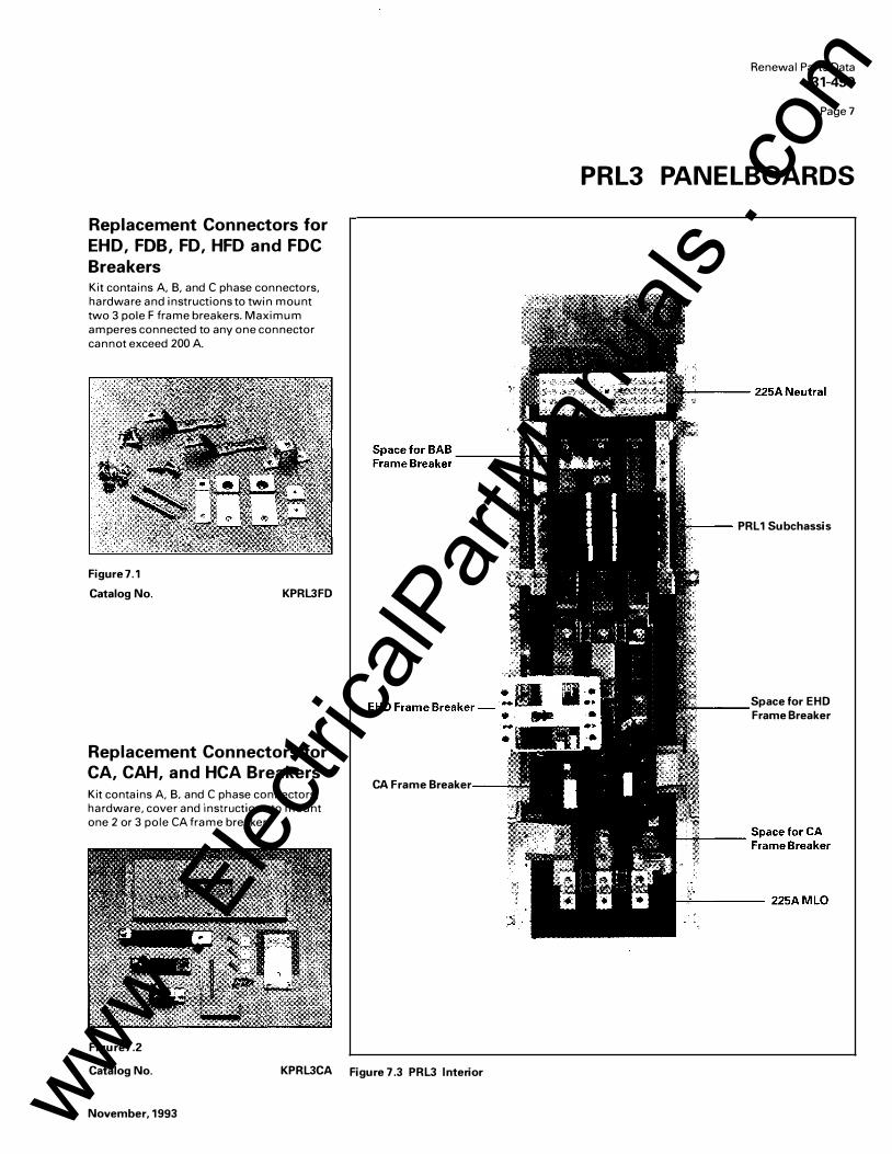
Replacement Connectors for
EHD, FOB, FD, HFD and FDC
Breakers Kit contains A, B, and C phase connectors, hardware and instructions to twin mount two 3 pole F frame breakers. Maximum amperes connected to any one connector cannot exceed 200 A.
Figure 7.1
Catalog No. KPRL3FD
Replacement Connectors for
CA, CAH, and HCA Breakers Kit contains A, B. and C phase connectors, hardware, cover and instructions to mount one 2 or 3 pole CA frame breaker.
Figure7.2
CA Frame Breaker
Catalog No. KPRL3CA Figure 7.3 PRL3 Interior
November, 1993
Renewal Parts Data
31-490
Page7
PRL3 PANELBOARDS
--- PRL 1 Subchassis
Space for EHD ,___ ___ Frame Breaker
www . El
ectric
alPar
tMan
uals
. com

Renewal Parts Data
31-490
PageS
PRL4 PANELBOARDS
PRL4B PRL4F
------ NP ----....;
---Top Vented Cover ---
---- Blank Cover ----
---- Side Gutter Cover
Device Cover
Extension Wing
Bottom Vented Cover
Figure 8.1 PRL4B and PRL4F
Vented Cover Assemblies and Side Gutter Covers NEMA 1 Box Vented Side Gutter Covers
Dimensions (in.) Catalog Cover Assembly C2l Left Right H w D CD No. Size (in.) Style No. Size (in.)
57 24 10.4 BX2457 CVRASSY2457 5 X 57 6555C20H01 5 x 57
73 24 10.4 BX2473 CVRASSY2473 5 X 73 6555C21H01 5 x 73
90 24 10.4 BX2490 CVRASSY2490 5 x90 6555C25H01 5 X 90
73 36 10.4 BX3673 CVRASSY3673 6 X 73 6555C22H01 8 x 73
90 36 10.4 BX3690 CVRASSY3690 6 x 90 6555C26H01 8 x 90
73 44 10.4 BX4473 CVRASSY3673 8 x 73 6555C23H01 14 X 73
90 44 10.4 BX4490 CVRASSY3690 8 x 90 6555C27H01 14x90
CD Covers add .90 inches to box depth for overall enclosure depth of 11.30 inches.
C2l Cover Assembly consists of 2 side rails, top and bottom vented covers, individual device
covers and or/blank covers. Important: Layout information must be provided with an order.
Style No. 6555C20H01 6555C21H01 6555C25H01
6555C23H01 6555C27H01
6555C24H01 6555C28H01
November, 1993 www . El
ectric
alPar
tMan
uals
. com

PRL4 Blank Covers
Used to cover blank space on chassis. All PRL4 cover heights are measured in "X" units. 1X equals 1 3/8 inches.
Cover Style Number
Size 24"W Box 36/ 44"W Box
1X 6554C01H01 6554C02H01
2X 6554C01H02 6554C02H02
3X 6554C01H03 6554C02H03
4X 6554C01H13 6554C02H13
5X 6554C01H14 6554C02H14 ------ -·- ·---�-� 6X 6554C01H04 6554C02H04
7X 6554C01H05 6554C02H05
9X 6554C01H06 6554C02H06
10X 6554C01H07 6554C02H07
11X 6554C01H08 6554C02H08 � · _. ___ ·-12X 6554C01H09 6554C02H09
13X 6554C01H10 6554C02H10
15X 6554C01H11 6554C02H11
20X 6554C01H12 6554C02H12
November, 1993
Figure 9.1 PRL4B Interior
Renewal Parts Data
31-490
Page9
PRL4 PANELBOARDS
Neutral
1200AMLO
Twin Mounted Breakers
Single Mounted Breakers
Breaker Provision
Space Only
www . El
ectric
alPar
tMan
uals
. com

Renewal Parts Data
31-490
Page 10
PRL4 PANELBOARDS
PRL4 Breaker Connector Kits Each kit includes copper connectors, mounting brackets, covers, hardware and instructions for mounting breaker(s) in a
PRL4. BREAKERS ARE NOT INCLUDED. Contact your local Satellite plant for availability and application information.
Space Required Inches "X"
----2.750 2X
- --- -- - --- --- --
4.125 3X --- ·--·-
- - - ----
5 .500 4X
- - - - ----
8.250 6X
Breaker Frames
EHD, FD, HFD EHD, FD, FOB, HFD, FDC CA, CAJ::L HCA EHD, FD, FOB, HFD, FDC FCL, FB-P, FD/LFD CA. CAH, HCA JD, JOB, HJD, JDC JD, JOB, HJD, JDC
Poles
1(j) - ----2
-e------- --
3
- --------2,3
---- --------- --- ---r----OK, KD, KDB,HKD, KDC DK,KD,KDB, HKD,KDC 2,3 CKD, CHKD -----
LCL LA-P LD,LDB,HLD,LDC,CLD,LC MC, MCC, HMC, MCY,MDS 2,3 NB-P NC�HNC, NCY CND, CHND 3 ND,HND
PRL4 Fusible FOP Connector Kits
Type of Connector kit Mounting Catalog No. twin KPRL4FD1 - - - - -- - -r-- - - ------twin KPRL4FD2 twin KPRL4CA2 ---- --- --- ---- ---- -- -- --
twin KPRL4FD twin KPRL4FBP twin KPRL4CA
- ------- ----- ---r-------------- ---
single KPRL4JDS twin KPRL4JDT (2) single KPRL4KDS twin KPRL4KDT Ql
f--- single ---
KPRL�KD@) ----
single KPRL4LCL (2) single KPRL4LAP (2) single KPRL4LD (2) single KPRL4MC (2) single KPRL4NBP Q) single KPRL4NC (2) single KPRL4CND Q) @) single KPRL4ND (2)
Each kit includes copper connectors, extension wings ( when required). hardware and instructions to horizontally mount an FOP switch. SWITCHES ARE NOT INCLUDED. Contact your local Satellite plant for availability and application information.
Switch Height Switch Inches "X" space Rating
30A/30A 5 .500 4X 60A/60A
100A/100A 6.875 5 X 100A 6.875 5X 100A/100A 8.25 0 6X 200A
�j25 r- - --- -
11X 400A 15 .125 11X 600A
- - - - --
22.000 16X 800A 22.000 16X 1200A
CD Two sets of twin mounted 1 pole breakers. (2) 3 6" minimum box width required. Ql 44" box width required.
·---
@) Requires density rated bus in existing panel chassis.
3P FOP Catalog No. Connector Kit 240V 600V Catalog No.
FDPT3211R FDPT3611R FDPT3222R FDPT3622R KPRL44X FDPT3233R -
FDPS323R FDPS363R KPRL45XS - FDPT3633R KPRL45X FDPS324R FDPS364R KPRL46X
------------- - - -- -- - - ----
FDP325 R FDP365R KPRL411X FDP326R FDP3 66R KPRL411X
----- - --- - ------ --- --- - ----- FDPS367R KPRL416X Q) -- FDPS368R KPRL416X Q)
November, 1993 www . El
ectric
alPar
tMan
uals
. com

Renewal Parts Data
31-490
Page 1 1
PRL4 PANELBOARDS
PRL4 Fusible FDPW Connector Kits
The FDPW switch design was first introduced in 1992 and will eventually replace the FDP line of switches. A new 200A twin switch is also offered. Each kit includes copper connectors, extension wings ( when required), hardware and instructions to horizontally mount an F DPW switch. SWITCHES ARE NOT INCLUDED. Contact your local Satellite plant for availability and application information.
Switch Height Switch Inches "X" space Rating 8.250 6X 200N200A
12.375 9X 400A ------ --- - ---- ----15.125 11X 600A 15 . 125 11X SOOA
Connector Kit
Each kit includes copper connectors, mounting brackets, covers, hardware and instructions
Figure 11.1
3P FDPW Catalog No. Connector Kit 240V
FDPWT3244R FDPW325 R --
--FDPW326R FDPW327
Hardware Kit
Each kit includes mounting bracket( s) and mounting hardware ONLY. Use the appropriate Connector Kit catalog number and add an "H" to designate hardware only. (Example: KPRL4FD-H)
Figure11.2
--
600V Catalog No. FDPWT3644J KPRL4W6XT CD
FDPW365 R KPRL4W9X - --------- --·-- -------FDPW366R KPRL4W11X FDPW367 KPRL4W11X CD
Standard Ground Bus
Copper bus with 3 # 6-300MCM lugs plus a 24 circuit terminal bar with # 14- 1/0 wire range.
Figure 11.3 Style No. 6572C74G01
CD 44" box width required for both R and J fuse applications.
November, 1993 www . El
ectric
alPar
tMan
uals
. com
Renewal Parts Data 31-490
Page 12
PRL4 PANELBOARDS
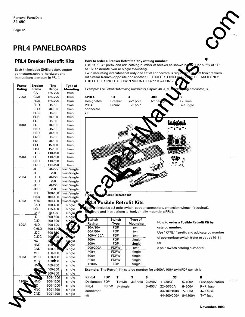
PRL4 Breaker Retrofit Kits
Each kit includes ONE breaker, copper connectors, covers, hardware and instructions to mount in PRL4.
Frame Breaker Trip Type of Rating Frame Range Mounting
CA 125-225 twin 225A CAH 125-225 twin
HCA 125-225 twin --- E.� -----··r-
·--.·
-15-60 twtn EHD 70- 100 twin FOB 15-60 twin FOB 70-100 twin FD 15-60 twin
100A FD 70-100 twin HFD 15-60 twin HFD 70- 100 twin FDC 15-60 twin FDC 70-100 twin FCL 15-100 twin FB- P 15-100 twin ---- · · ·· �=� t-- -
1 10- 150 twin 150A FD 110-150 twin
HFD 110-150 twin FDC 110- 150 twin ------J� t--70-225 twin/single JD 250 twin/single
250A HJD 70-225 twin/single HJD 250 twin/single JDC 70-225 twin/single
f--- JDC 250 twin/sin�� KD 100-400 twin/single HKD 100-400 twin/single
400A KDC 100-400 twin/single CKD 100-400 single LCL 125-400 single
-·· LA- P 70-400 single LD 300-600 single CLD 300-600 single
600A HLD 300-600 single CHLD 300-600 single LDC 300-600 single CLDC 300-600 single -· ND
·---�-400-800
HND 400-800 single CND 400-800 single MC 400-800 single
800A MCC 400-800 single MCY 400-800 single HMC 400-800 single HMCC 400-800 single NB- P 300-800 single ---NO
-60o:i260 -- · .--single
1200A HND 600-1200 single NC 600-1200 single HNC 600-1200 single CND 600-1200 single
How to order a Breaker Retrofit Kit by catalog number: Use "KPRL4" prefix and add catalog number of breaker as shown below. Use suffix of "T" or "S" to denote twin or single mounting. Twin mounting indicates that only one set of connectors is required to mount two breakers (of similar frames) opposite one another. RETROFIT KIT INCLUDES ONE BREAKER ONLY, FOR EITHER SINGLE OR TWIN MOUNTED APPLICATIONS.
Example: The Retrofit Kit catalog number for a 3 pole, 400A, KD breaker, single mounted, is:
KPRL4 KD 3 400 s Designates Breaker 2=2 pole Amperage T= Twin PRL4 Frame 3=3 pole S= Single connector kit
... ,. , ..
Figure 12.1 Breaker Retrofit Kit
PRL4 Fusible Retrofit Kits Each kit includes a 3 pole switch, copper connectors, extension wings (if required). hardware and instructions to horizontally mount in a PRL4.
Switch Switch Rating Type 30A/30A FOP 60A/60A FOP !QOA/100� FOP 100A FOP 200A FOP 200/200A FDPW r---c--_ -·· ---- -400A FDPW 600A FDPW 800A FDPW 1200A FOP
Type of Mounting
twin twin twin
single sin�le __ twtn - ----
single single single single
How to order a Fusible Retrofit Kit by
catalog number:
Use "KPRL4" prefix and add catalog number
of appropriate switch (refer to pages 10- 11
for
3 pole switch catalog numbers).
Example: The Retrofit Kit catalog number for a 600V, 100A twin FOP switch is:
KPRL4 FOP Designates FOP
PRL4 FDPW
connector
kit
T 3 6 T =twin 3=3pole 2=240V
S=single 6=600V
33 R 1 1=30/30 5=400A Fuse application
22=60/60A 6=600A R=R fuse
33= 1 00/ 1 OOA 7=800A J=J fuse
44=200/200A 8=1200A T =T fuse
November, 1993 www . El
ectric
alPar
tMan
uals
. com

Energy Sentinel
The 10 Energy Sentinel is a submetering device that mounts directly on a circuit breaker and monitors both power and energy with an overall accuracy of 99%. This high system accuracy is achieved by use of the Westinghouse Distribution and Control SURE Plus Chip, which is a sophisticated microprocessor.
All that is necessary to complete an 10 Energy Sentinel installation is to insert it into the load side of a breaker; feed the load conductors through it; connect a neutral wire; and run the shielded twisted pair wire for communications. The 10 Energy Sentinel has a nonvolatile memory, is powered by the circuit breaker, and can be applied on three-phase, four-wire or single phase, three wire systems.
Energy Sentinel
Figure 13.2
10 Central Energy Display
Figure 13.3
November, 1993
Renewal Parts Data
31-490
Page 13
PRL4 PANELBOARDS
The space saving design characteristics of the 10 Energy Sentinels means they can be quickly and easily retrofitted onto Series C circuit breakers in existing equipment ... with no additional space required. Additionally, 10 Energy Sentinels £_an be installed when upgrading to Series C from older breakers that are physically interchangea ble ... with no additional space requirements.
Power and energy information from 10 Energy Sentinels can be communicated to a PC, a panel mounted Central Energy Display (CED), or even existing building management or distribution control systems.
Figure 13.1
----
Series C Breaker Frame
-- ------F
F
J J ------K
K
Voltage Max. AC Amps
120/208, 120/240 150
277/480 150 ----120/208, 120/240 250
277/480 250 -- -···---120/208, 120/240 400
277/480 400
Energy Sentinel Catalog Number
IOESF208
IOESF480
IOESJ208
IOESJ480
IQESK208
IOESK480
The 10 Central Energy Display may be panel mounted or located remotely ( up to 7500 feet away). I t displays power, peak d emand, and energy readings of up to fifty 10 Energy Sentinels and eight 10 Data Plus II digital meters.
Additional capabilities include: peak demand alarming, demand and energy totals for groups of 10 Energy Sentinels and 10 Data Plus II meters, and communication of data to a remote PC.
Refer to DB 8178 for further technical information.
Refer to your local Satellite for retrofit and upgrade options available for existing equipment.
www . El
ectric
alPar
tMan
uals
. com

Renewal Parts Data
31-490
Page 14
PRL 1/2/3 SPECIAL TRIMS and ENCLOSURES
Ventilated Trim
Required on PRL 1 and PRL2, 600 A panels only. Order by adding the letter "V" to the standard trim catalog number. ADD 10% TO STANDARD TRIM LIST PRICE. Example: L T2072S becomes LTV2072S Refer to page 4 for the standard trim catalog numbers.
Figure 14.1
NEMA 12/3R Enclosures
Figure14.4
Fastrim Used when concealed trim mounting hardware is required for PRL 1, PRL2, and PRL3. Flush trim utilizes style number 414A380G0 1 trim clamps.Surface trim utilizes style number 87 12C73 H0 1 trim clamps. Trim clamps are included and shipped with the trim. Order by adding the letter "F" to the standard trim catalog number. ADD 20% TO STANDARD TRIM LIST PRICE. Example: L T2072S becomesLTF2072S. Refer to pages 4 and 6 for standard trim catalog numbers.
Figure 14.2
Door-In-Door Trim Piano hinge on the right side of the trim provides access to the wiring gutters without requiring removal of the trim. Order by adding the letters "DD" to the standard trim catalog number. ADD 20% TO STANDARD TRIM LIST PRICE. Example: L T2072S becomesLTDD2072S. Refer to pages 4 and 6 for standard trim catalog numbers.
Figure 14.3
The complete enclosure consists of a box and trim. The enclosure meets code requirements for both NEMA 12 (dusttight) and NEMA 3R ( rainproof) standards. Features include a laser cut trim with rounded corners, concealed hinges and a T- handle lock. Gasketing is provided around the trim door. The gasketed box is made of code gauge steel with dripshield and is painted ASA- 61
NEMA 12/N3R Enclosures for PRL 1/2/3
Box Dim. (in.) Catalog Numbers H w D Box PRL 1/2 Trim
24 20 6 GWPB2024 LWPT2024 36 20 6 GWPB2036 LWPT2036 48 20 _ _ §__ GWPB2048 LWPT2048 -60 20 6 GWPB2060 LWPT2060 72 20 6 GWPB2072 LWPT2072 78 20 6 GWPB2078 LWPT2078
PRL3 Trim - - - -LWT2036 LWT2048 LWT2060 LWT2072 LWT2078
November, 1993 www . El
ectric
alPar
tMan
uals
. com
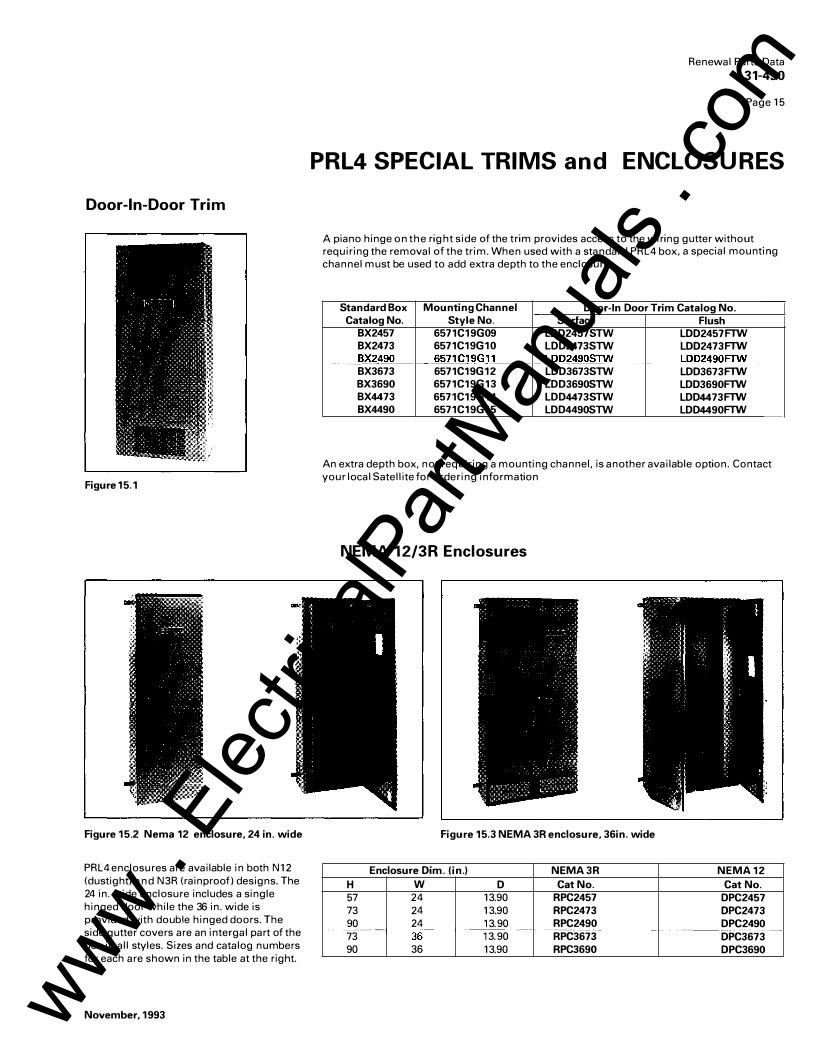
Door-In-Door Trim
Figure15. 1
Figure 15.2 Nema 12 enclosure, 24 in. wide
PRL4 enclosures are available in both N12 (dustight) and N3R (rainproof) designs. The 24 in. wide enclosure includes a single hinged door while the 36 in. wide is provided with double hinged doors. The side gutter covers are an intergal part of the box in all styles. Sizes and catalog numbers for each are shown in the table at the right.
November, 1993
Renewal Parts Data
31-490
Page 1 5
PRL4 SPECIAL TRIMS and ENCLOS URES
A piano hinge on the right side of the trim provides access to the wiring gutter without requiring the removal of the trim. When used with a standard PRL4 box, a special mounting channel must be used to add extra depth to the enclosure.
Standard Box Mounting Channel Door-In Door Trim Catalog No. Catalog No. Style No. Surface Flush
BX2457 6571C19G09 LDD2457STW LDD2457FTW BX2473 6571C19G10 LDD2473STW LDD2473FTW
_ _ B)(�490 6571C19GJl__ LDD2�0STW ___ LDD24�!)Fll/ll _ ---BX3673 6571C19G12 LDD3673STW LDD3673FTW BX3690 6571C19G13 LDD3690STW LDD3690FTW BX4473 6571C19G14 LDD4473STW LDD4473FTW BX4490 6571C19G15 LDD4490STW LDD4490FTW
An extra depth box, not requiring a mounting channel, is another available option. Contact your local Satellite for ordering information
NEMA 12/3R Enclosures
Figure 15.3 NEMA 3R enclosure, 36in. wide
Enclosure Dim. (in.) H w 57 24 73 24 90 24 -------n--- -t--36--90 36
D 13.90 13.90 13.90 r-- ----- -----13.90 13.90
NEMA 3R Cat No.
RPC2457 RPC2473 RPC2490 ---- ---·-RPC3673 RPC3690
NEMA 12 Cat No.
DPC2457 DPC2473 DPC2490
---- - ------DPC3673 DPC3690
www . El
ectric
alPar
tMan
uals
. com

Renewal Parts Data 31-490
Page 1 6
COLUMN TYPE PANELS
PRL 1-LX Replacement Boxes and Trims
Standard box includes box ends at top and bottom.
Box for trough is supplied with bottom box end only.
Contact the Orlando Satellite for availability and application information.
Box dimensions (in.) Standard Box for
H w D Box Trouqh
42 8.63 5 114D939G10 114D939G26
54 8.63 5 114D939G12 114D939G28
66 8.63 5 114D939G14 114D939G30
78 8.63 5 114D939G16 114D939G32
PRL3-LX Replacement Boxes and Trims
Standard box includes box ends at top and bottom.
Box for trough is supplied with bottom box end only.
Design is for top feed application only.
Surface
Trim
6724D78G10
6724D78G12
6724D78G14
6724D78G16
Contact the Orlando Satellite for availability and application information.
Panel Box dimensions (in.) Standard Box for Surface
Type H w D Box Trough Trim
40.75 8.63 5.75 6726D69G01 6726D69G07 6726D70G01
Main 49.00 8.63 5.75 6726C69G02 6726C69G08 6726D70G02
Lug 57.25 8.63 5.75 6726C69G03 6726C69G09 6726D70G03
Only 65.50 8.63 5.75 6726C69G04 6726C69G10 6726070G04
(top feed) 73.75 8.63 5.75 6726C69G05 6726C69G11 6726D70G05
82.00 8.63 5.75 6726C69G06 6726C69G12 6726D70G06
51.7 5 8.63 5.75 6726C69G13 6726D69G19 6726D70G07
Main 60.00 8.63 5.75 6726D69G14 6726D69G20 6726D70G08
Breaker 68.25 8.63 5.75 6726D69G15 6726D69G21 6726D70G09
( top feed) 7 6.50 8.63 5.75 6726D69G16 6726D69G22 6726D70G10
84.75 8.63 5.75 6726D69G17 6726D69G23 6726D70G11
93.00 8.63 5.75 6726D69G18 6726D69G24 6726D70G12
Replacement Connectors for
BAB Breakers
Kit contains two sets of A, B, and C phase copper connectors, hardware and instructions to mount up to 6 poles.
Figure 16.1
Catalog No. KPRL1LXBAB
Replacement Connectors for
EHD Breakers
Kit contains two sets of A, B, and C phase copper connectors, hardware and instructions to mount up to 6 poles.
Figure16.2
Catalog No. KPRL3LXEHD
November, 1993 www . El
ectric
alPar
tMan
uals
. com

Renewal Parts Data
31-490
Page 1 7
POW-R-KIT
Figure17.1
November, 1993
Kit contains an assortment of Pow-A - L ine C panel board and switchboard parts. The listed price is an annual
charge with unlimited reorders allowed for one year. The insulated bag shown in Figure 1 7 . 1 ships with the
initial order as well as the maximum quantities of all items shown below. Minimum reorder must contain at
least three separate items, in any quantities up to the maximum indicated. I ndividual items are not sold
separately, although the local Satellite may be contacted if large quantities of a particular item are required.
Order the kit by using catalog number POWRKIT.
Description Style Maximum Number Order Qty.
PRL 1/2 neutral plastic base 5156C05H01 10 PRL 1/2/3 alum ground bus (YS2 0 2 7 & under) 5158C05G01 2 PRL 1/2/3 alum ground bus (YS2 030 & over) 5158C05G02 2
_ PRL 1/2}3 chas�s mounting hardwa_re ___ ------1-- _ 749�A48�_1!_4_ ____ _ __ _ __ 5 ___ _ PRL 1/2/3 trim mounting screws (slotted or flush) 5157C83G06 10 PRL 1/2 breaker mounting screws 70010KSC8G 100 PRL 1/2/3 dead front cover mounting screws 70010KPCMJ 50
-�AB/GH13 1 pole fil� _ _ ______ _ _____ ____ ___ 5�55(:_6�1:10_ 1__ _ _____§_ 0 __ _ E,F Frame 1 pole fillers 114B408H01 10 Directory card envelope (stick-on) 6725D41H30 2 Directory card 1148361H01 25 Number tabs 1-4 2 267P963H01 10 f'.iUmber-tabs43�84
__ ______ --- - ----- -�S7P9G3H0-2
--- -r- --- - - --5----
PRL4 chassis mounting hardware 5081A08G02 5 PRI4 gutter cover mounting hardware 5081A09G02 5
__ f"RL4/P_RL C dead front cover screws ________ r- _____1Q!>_10DCBCH ______ -r---PRL C switchboard cover screws 1A84774H01 PRL C switchboard .44 square hole plug 8450C62H17 PRL 1/2/3 dead front cover .25 round hole plug 76260ES10C Panelboard lock assembly 5155C81G01
- 25 -- -25 25 10
2
--
www . El
ectric
alPar
tMan
uals
. com
Renewal Parts Data
31-490
Page 1 8
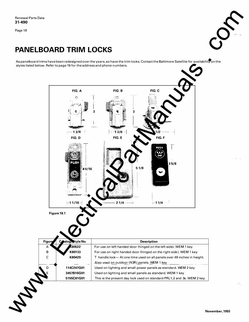
PANELBOARD TRIM LOCKS
As panel board trims have been redesigned over the years, so have the trim locks. Contact the Baltimore Satellite for availability on the styles l isted below. Refer to page 19 for the address and phone numbers.
FIG. A FIG. B FIG. C
:·'ll I, ."lt I
3 3
Figure 18.1
- �� '1!\ltm ....
��1 318 �I FIG. D
H 1/16�j
Figure Catalog/Style No.
A K80522
B K80133
c K80429
------D 114C247G01
E 3457B16G01
F 5155C81G01
-·
i �L
FIG. E
2 1/4 ------i
---2 1/2 ---- � FIG. F
5 1/8
I f-1 1/4
Description
For use on left handed door ( hinged on the left side). W EM 1 key
For use on right handed door (hinged on the right side). W EM 1 key
T handle lock- At one time used on all panels over 48 inches in height.
Als()_used on outdoor (N3R) panels. WEM 1 key __________ .-- _ Used on lighting and small power panels as standard. WEM 2 key
Used on lighting and small panels as standard. W EM 1 key
This is the present day lock used on standard PRL 1,2 and 3s. W EM 2 key.
November, 1993 www . El
ectric
alPar
tMan
uals
. com

,CJ
Atlanta 799 0-A 2nd Flag Dr. Austell, GA 3000 1 Fax (404) 944- 2033 Phone (404) 9 44- 1022
Baltimore/Washington 6671 Santa Barbara Court Elkridge, MD 2 1227 Fax (410) 79 6- 7755 Phone (410) 79 6-7 7 7 7
Chicago 195 1 Touhy Avenue Elk Grove Village, IL 60007 Fax ( 708)439-309 2 Phone ( 7 08)439 -3070
Dallas 9 13 W. North Carrier Pkwy Grand Prairie, TX 75050 Fax ( 2 14) 641- 6435 Phone (2 14) 988-3339
November, 1993
Denver
• Denver
14101 East33rd Place Suite F Aurora, CO 8 00 11 Fax (303)37 1-4175 Phone (303) 371-78 44
Hartford 507 Hayden Station Rd. Windsor, CT 06095 Fax (203) 688 -498 2 Phone ( 203) 688 -5330
Houston 2523 Fairway Park Dr. Suite 516 Houston, TX 7 709 2 Fax ( 7 13) 688 -3764 Phone ( 713) 688 -8 430
Los Angeles 202 1 Locust Court Ontario, CA 9 1 7 6 1 Fax (9 09)9 23-2344 Phone (9 09) 9 23-2040
Renewal Parts Data
31-490
Page 19
S ATELLITE PLANTS
Orlando Seattle 38 27 St. Valentine Way 18 65 7 72nd Avenue S. Orlando, FL 328 1 1 Kent, WA98 032 Fax (407) 8 41-9 135 Fax (206) 25 1-0079 Phone (407)8 43-38 63 Phone (20 6) 251-9 08 1
Philadelphia 508 Lapp Rd. Malvern. PA 19 335 Fax ( 2 15) 640-099 4 Phone ( 2 15) 889 -3554
St. Louis 129 47 Gravois Rd. St. Louis, MO 63127 Fax (3 14)8 42-2552 Phone (314)8 42- 779 7
San Francisco 209 19 Cabot Blvd Hayward, CA94545 Fax (510) 78 4-898 0 Phone (510) 784-898 1
www . El
ectric
alPar
tMan
uals
. com

Renewal Parts Data
31-490
Page 20
Additional Service
Since virtually all panelboards are supplied to meet specific customer requirements, other parts not listed in this publication might occasionally be needed. Price and availability for parts not shown here may be obtained by contacting your local Satellite and providing a complete description of the part, along with the data on the panel board nameplate.
Should you experience difficulty in determining what replacement parts are needed, contact your local Westinghouse Satellite manager, who can provide help to:
Identify and recommend replacement parts.
Remove damaged parts and install re placements.
Verify the correct connector kits which should be ordered for each circuit breaker or fusible switch.
Retrofit existing panel board boxes with new Pow-R-Line E interiors.
Provide a recommended spare parts list.
Westinghouse Electric Corporation Distribution and Control Business Unit Construction Equipment Division Pittsburgh, Pennsylvania, U.S.A. 15220
Printed in U.S.A.
November, 1993 www . El
ectric
alPar
tMan
uals
. com