panduit visio design tool help guide 6 · pdf fileprogram description the panduit design tool...
TRANSCRIPT

Program Description
The Panduit Design Tool for Visio is a software package developed to run in conjunction with
Microsoft Visio 2010 through 2016. The Software allows the user to create a 2-dimensional
layout using Panduit’s Data Communication, Telecommunicationsand Cabler Routing products.
Once a design is complete, a Bill of Material may be generated.
The Panduit components included in the Visio stencils are Racks, Net-Access™ Cabinets, Aisle
Containment, Cable Management , Copper Modules, Fiber Adapters, Copper and Fiber Patch
Panels, Enclosures, Managed Network Systems, PanZone®, QUICKNET™, Punch-down
Products, Wall Mount Products, Top Views, Shielded Products, Wiring Accessories, Wyr-
Grid®, Raised-Under Floor (new Cool Boot™), Fiber-Duct™ 2x2 and 4x4 as well as
FiberRunner™ 2x2, 4x4, 6x4, 12x4 and 24x4.
Features
The Panduit Design Tool for Visio v6.0 provides many features that aid in the creation of a fiber
routing, telecommunications room or data center layout, including:
2D shapes of product lines mentioned above.
Complete front views of Data Center / Telecommunications Room products.
Top views of racks, vertical cable mgmt, cabinets, phantom cabinets and ladder rack.
Complete top, front and right views for Fiber-Duct™, FiberRunner™, Raised-Under
Floor, and PanZone®.
Easy to use menus.
Drag and drop insertion capabilities.
Fill calculator / Product recommendation tool for FiberRunner™/Fiber-Duct™ and
Vertical Cable Management Products.
Accessories and Cable selection dialogs.
Bill of Material generator.
Link to Panduit site for partner's web sites.
Dialog to auto-populate the blank patch panels with jacks/adapters.
Dialog to auto-populate the racks, panels and panel ports with labels.
The Panduit menu is now available in the Visio Ribbon interface.

Software Requirements
Microsoft Visio 2010 or later installed. Visio versions 2000 through 2007 are not supported, although the Panduit shapes may be usable.
Microsoft .NET Framework 4.0 Windows Installer 2.0 or later. Microsoft Excel 2010 or later installed (optional).
Note: If your computer has automatic updates enabled, the latest versions of the .NET
Framework and Windows Installer should already be installed. If not, use the Microsoft
Update site (http://update.microsoft.com) to get the latest versions. These components were not
included in the download for the Panduit Design Tool install program in order to reduce the MSI
file size.
System Requirements
PC with 500 MHz or higher processor for Visio 2010. PC with 1 GHz or higher processor for Visio 2013 and Visio 2016. All other system requirements are based on the version of Visio you are running. This info is
available on http://www.microsoft.com. CD-ROM drive. 1280 x 800 or higher-resolution monitor The Panduit Visio Design Tool requires hard disk space of 135MB for templates, stencils, and
support files
Installation Instructions
From the Web:
1. Uninstall any previous versions of the Panduit Design Tool for Visio. 2. Go to www.panduit.com 3. Select "Support" 4. Select "Design Tools" 5. Under "Data Center Design Tools", select the version of the tool based on the version of Visio
you have on your PC. 6. Fill out the registration if it appears. (If registration has previously been completed, you will go
straight to a dialog box.) 7. A dialog box appears to save the tool to a specific location. 8. Click Save and choose the location for the tool, either on your PC or your network. 9. In Windows Explorer, locate the .msi file saved in step 8 and double-click it.

New Features
This release of the Panduit Data Center Design Tool for Visio includes the following new
features:
New Data Center solution stencils: o Updated Wyr-Grid® Products o Universal Aisle Containment
Support for Visio versions 2010 through 2016. Support for 32-bit and 64-bit versions of Visio. The Panduit menu is now part of the Ribbon interface.
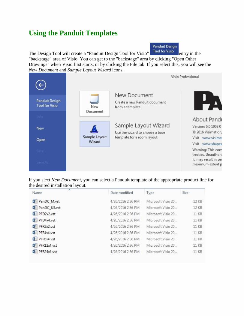
Using the Panduit Templates
The Design Tool will create a "Panduit Design Tool for Visio" entry in the
"backstage" area of Visio. You can get to the "backstage" area by clicking "Open Other
Drawings" when Visio first starts, or by clicking the File tab. If you select this, you will see the
New Document and Sample Layout Wizard icons.
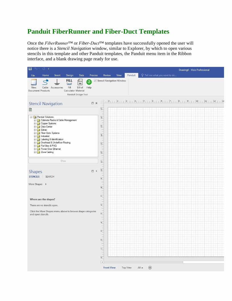
If you slect New Document, you can select a Panduit template of the appropriate product line for
the desired installation layout.

The templates you can choose from are described as follows:
PanDC_M.vst - Datacenter template, Metric units
PanDC_US.vst - Datacenter template, US (Imperial) units
PFD2x2.vst - 2X2 Fiber-Duct template
PFD4x4.vst - 4X4 Fiber-Duct template
PFR2x2.vst - 2X2 FiberRunner template
PFR4x4.vst - 4X4 FiberRunner template
PFR6x4.vst - 6X4 FiberRunner template
PFR12x4.vst - 12X4 FiberRunner template
PFR24x4.vst - 24X4 FiberRunner template
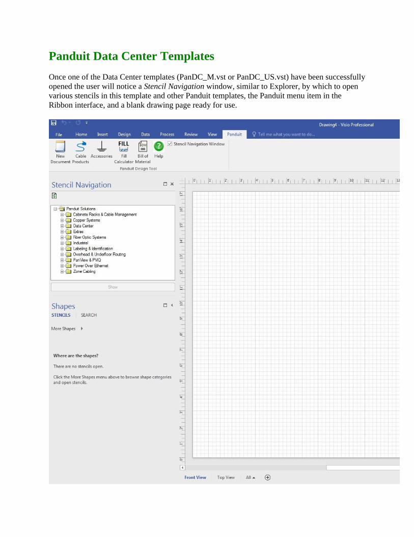
Panduit FiberRunner and Fiber-Duct Templates
Once the FiberRunner™ or Fiber-Duct™ templates have successfully opened the user will
notice there is a Stencil Navigation window, similar to Explorer, by which to open various
stencils in this template and other Panduit templates, the Panduit menu item in the Ribbon
interface, and a blank drawing page ready for use.

The drawing page is defaulted to Architectural 1/2" - 1' drawing scale with the page size at
Legal. If a different scale is needed, this can be changed by clicking Design, Page Setup,
Drawing Scale. Multiple pages can be inserted and set to whatever scale is needed. All of the
Panduit geometry has been created with the snap point locations predetermined for ease of use.
Finally, by simply utilizing Visio’s drag and drop feature, a fiber routing layout can easily be
created.
Panduit Data Center Templates
Once one of the Data Center templates (PanDC_M.vst or PanDC_US.vst) have been successfully
opened the user will notice a Stencil Navigation window, similar to Explorer, by which to open
various stencils in this template and other Panduit templates, the Panduit menu item in the
Ribbon interface, and a blank drawing page ready for use.

The two drawing pages will default to the following:
Front View - this view is set to Architectural 1/2" - 1' with the page size at Legal. This allows for detailing 2 rows of approximately 8 racks with cable management.
Top View - this view is set to Architectural 1/4" - 1' with the page size at 36" x 24". This allows for laying out an entire data center room.
If a different scale is needed, this can be changed by clicking Design, Page Setup, Drawing
Scale. Multiple pages can be inserted and set to whatever scale is needed. All of the Panduit
geometry has been created with the snap point locations predetermined for ease of use. Finally,
by simply utilizing Visio’s drag and drop feature, a Data Center layout can easily be created. A
metric template can also be selected which has similar settings for drawing scale and page layout
as mentioned above.
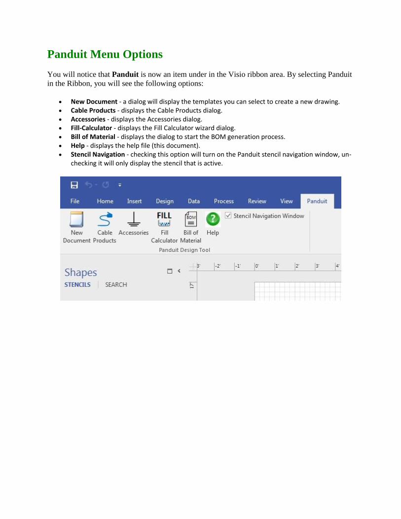
Panduit Menu Options
You will notice that Panduit is now an item under in the Visio ribbon area. By selecting Panduit
in the Ribbon, you will see the following options:
New Document - a dialog will display the templates you can select to create a new drawing. Cable Products - displays the Cable Products dialog. Accessories - displays the Accessories dialog. Fill-Calculator - displays the Fill Calculator wizard dialog. Bill of Material - displays the dialog to start the BOM generation process. Help - displays the help file (this document). Stencil Navigation - checking this option will turn on the Panduit stencil navigation window, un-
checking it will only display the stencil that is active.
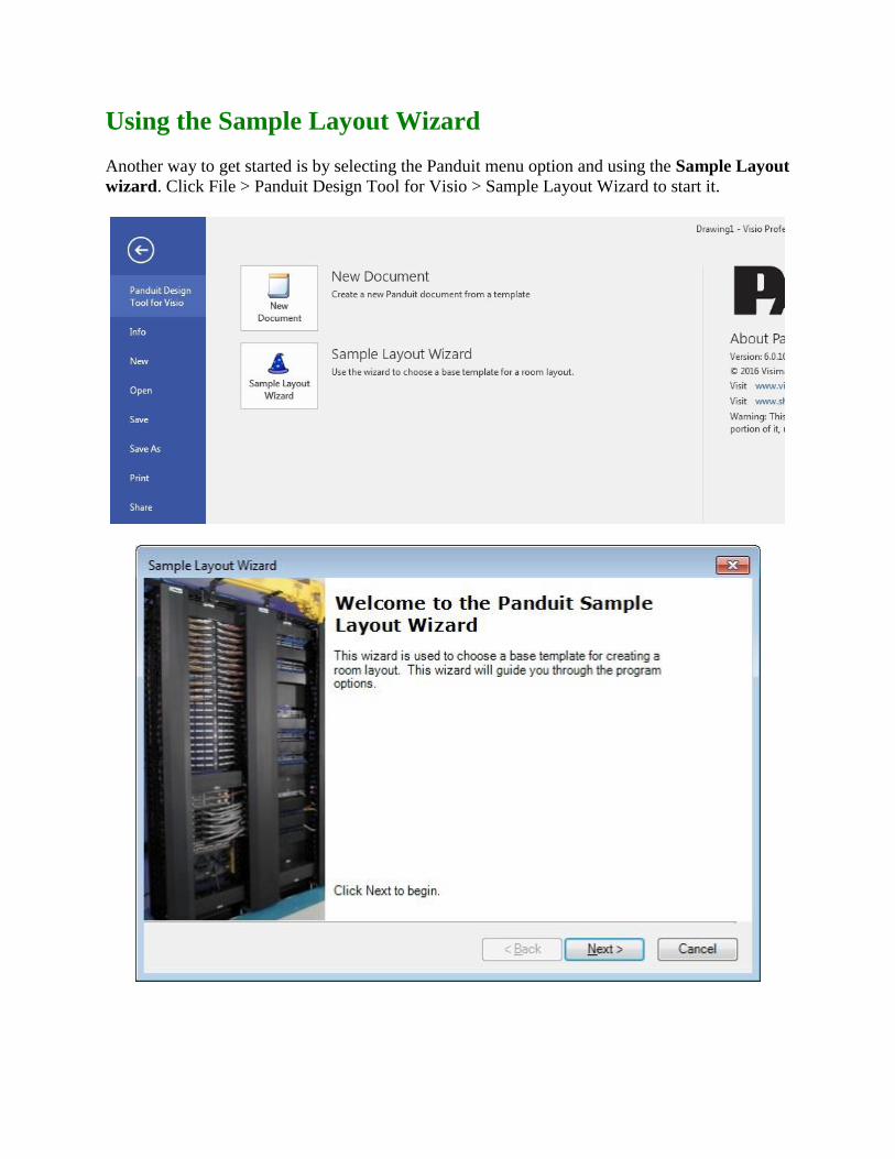
Using the Sample Layout Wizard
Another way to get started is by selecting the Panduit menu option and using the Sample Layout
wizard. Click File > Panduit Design Tool for Visio > Sample Layout Wizard to start it.

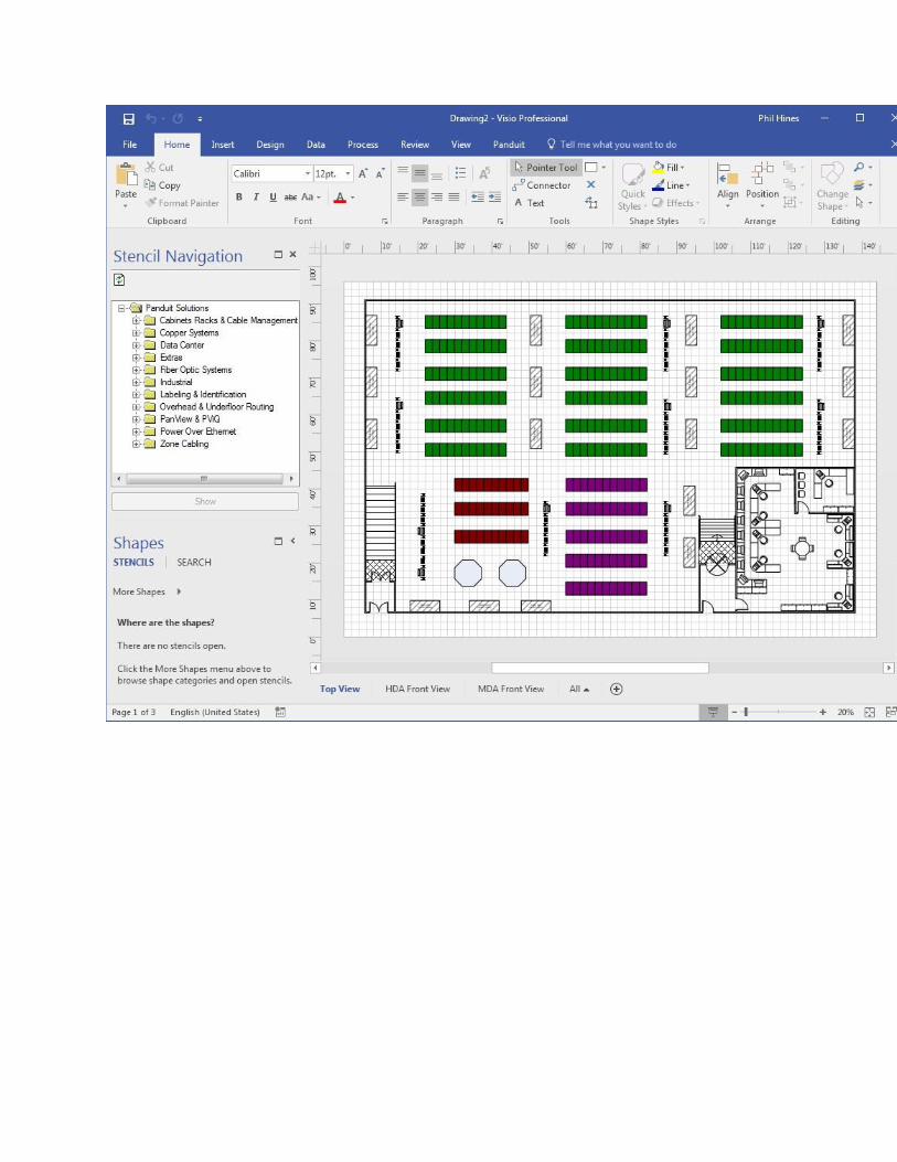
As you follow along with the wizard, you can select from 4 different data center room sizes for a
template to start with. These templates will give the user a top view along with a front view of
the MDA (main distribution area) and the HDA (horizontal distribution area).
Once the layout is displayed, the user can add to, delete and modify the layout as they see fit. It
is a guide or a place to start with a data center layout.

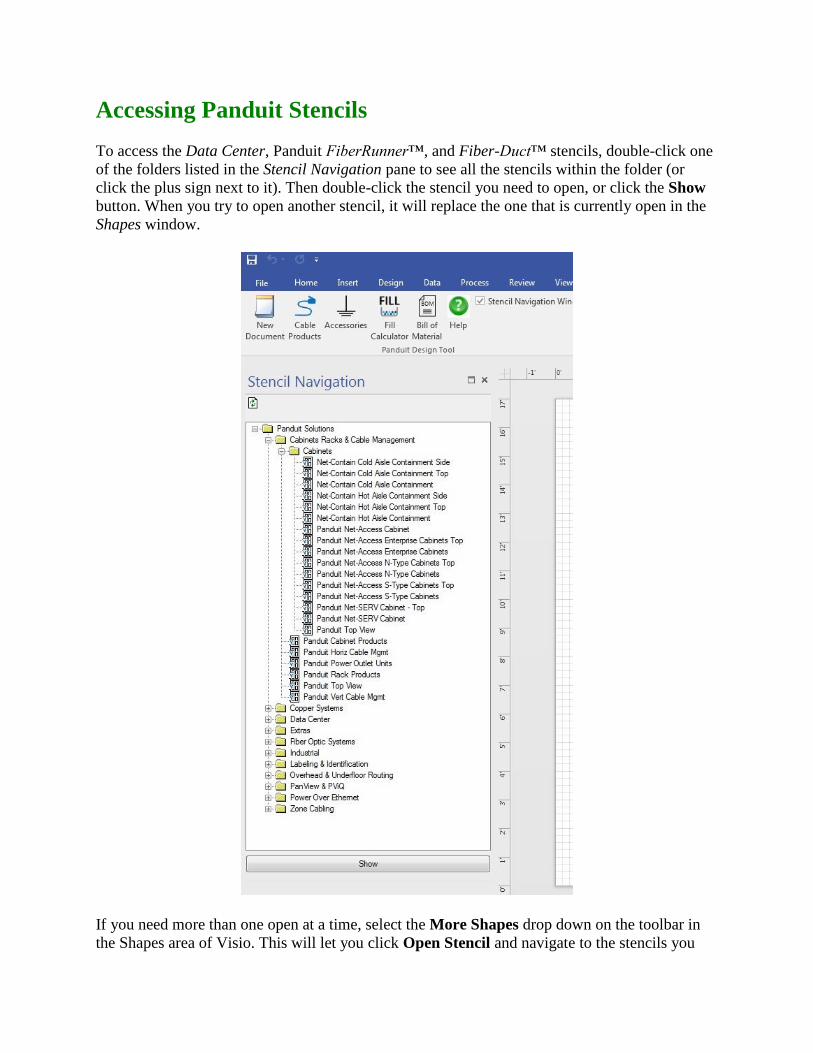
Accessing Panduit Stencils
To access the Data Center, Panduit FiberRunner™, and Fiber-Duct™ stencils, double-click one
of the folders listed in the Stencil Navigation pane to see all the stencils within the folder (or
click the plus sign next to it). Then double-click the stencil you need to open, or click the Show
button. When you try to open another stencil, it will replace the one that is currently open in the
Shapes window.
If you need more than one open at a time, select the More Shapes drop down on the toolbar in
the Shapes area of Visio. This will let you click Open Stencil and navigate to the stencils you

wish to open. You can also open the Visio standard stencils by clicking on a category and
navigating to a stencil.
(Visio 2010, 2013 and 2016 screen style)
These features allow the user to access specific stencils when working in other stencils/templates
and having more than 1 open at a time.

Panduit Fill Calculator
The Panduit Fill Calculator is a good place to begin when developing a layout. This
tool allows the user to select the appropriate fiber routing or vertical cable management product
line for their project. By selecting the Fill Calculator icon (shown left), the Panduit Fill
Calculator dialog is displayed.
Area Calculator
The area calculator computes the area of the cables that will be placed in the channel. A variety
of cable sizes may be added to the cumulative cable count and area total. Enter the quantity of
cable and the associated dimensions in the respective dialog boxes. Then, select the Add button
and the entered values are added to the existing totals. The user is also capable of removing line
items and clearing the entire field.
The area calculator works for both English and metric units. The conversion between units is
calculated automatically by selecting the inches or millimeter options. The Panduit Fill
Calculator supports round and flat cable, vertical cable managers, GridRunner CabinetRunner,
and Fiber Routing products.

Area Calculator
The Product Recommendation feature displays the acceptable product lines for the computed
cable area. The Future Expansion option displays the routing systems that have a fill capacity
under 40% for fiber routing and 33% for vertical cable managers. The Fill Channel Completely
option displays the systems that possess a fill capacity that is equal to or less than 60% for fiber
routing and 50% for vertical cable managers for the computed cable area.
Note: A full channel will occupy the product type’s respective maximum percent of the total
available area.
Product Recommendation
For the computed cable area, the fill percentage for the various routing product lines may be
calculated. Once the cable information has been entered and the cable area has been calculated,
select a product line and the resulting fill percentage is displayed.
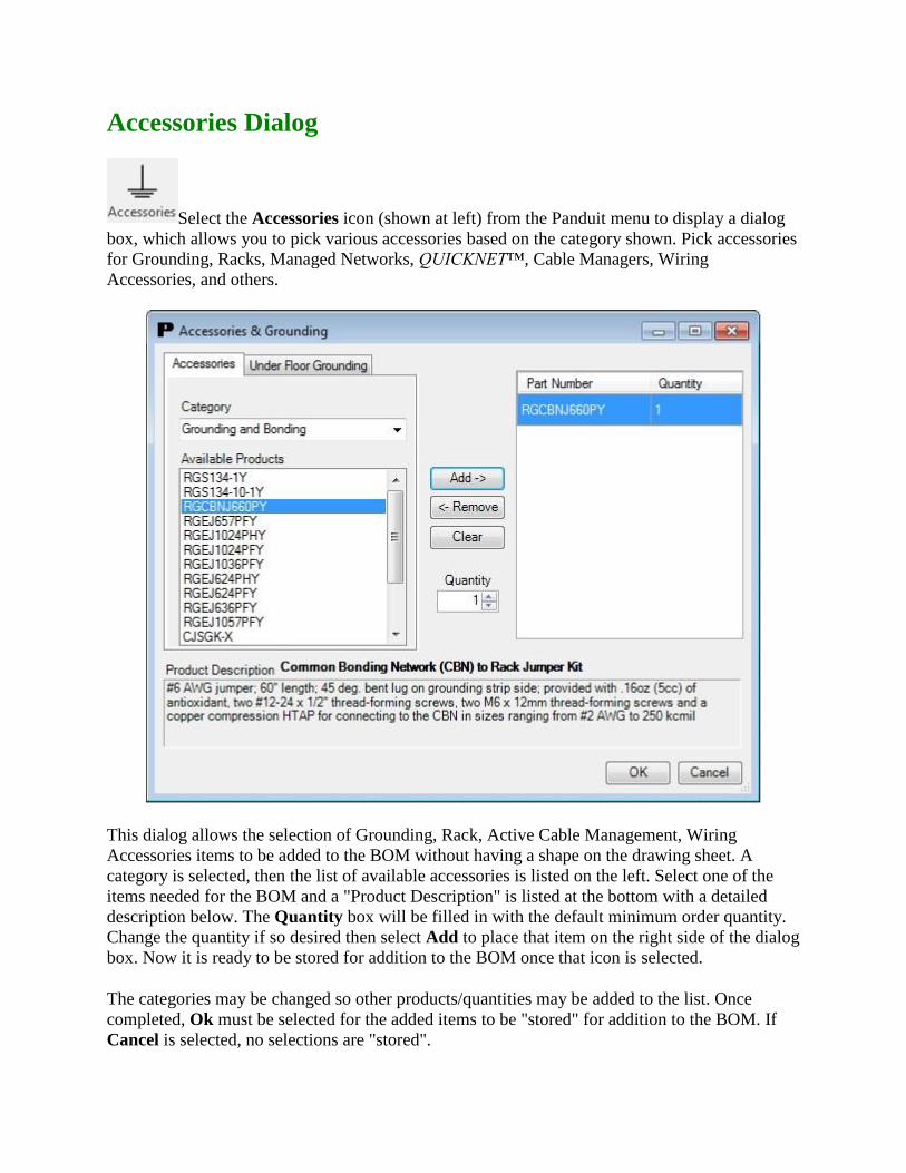
Accessories Dialog
Select the Accessories icon (shown at left) from the Panduit menu to display a dialog
box, which allows you to pick various accessories based on the category shown. Pick accessories
for Grounding, Racks, Managed Networks, QUICKNET™, Cable Managers, Wiring
Accessories, and others.
This dialog allows the selection of Grounding, Rack, Active Cable Management, Wiring
Accessories items to be added to the BOM without having a shape on the drawing sheet. A
category is selected, then the list of available accessories is listed on the left. Select one of the
items needed for the BOM and a "Product Description" is listed at the bottom with a detailed
description below. The Quantity box will be filled in with the default minimum order quantity.
Change the quantity if so desired then select Add to place that item on the right side of the dialog
box. Now it is ready to be stored for addition to the BOM once that icon is selected.
The categories may be changed so other products/quantities may be added to the list. Once
completed, Ok must be selected for the added items to be "stored" for addition to the BOM. If
Cancel is selected, no selections are "stored".

For the Under Floor Grounding tab, the user can input the area or the dimensions of the room
in English or Metric and the appropriate amount of under floor Grounding Clamps and HTAPS
will be listed. Then the user just selects the clamps and HTAPS, and clicks Add to place the
items on the right side of the dialog box so they can be added to the BOM.
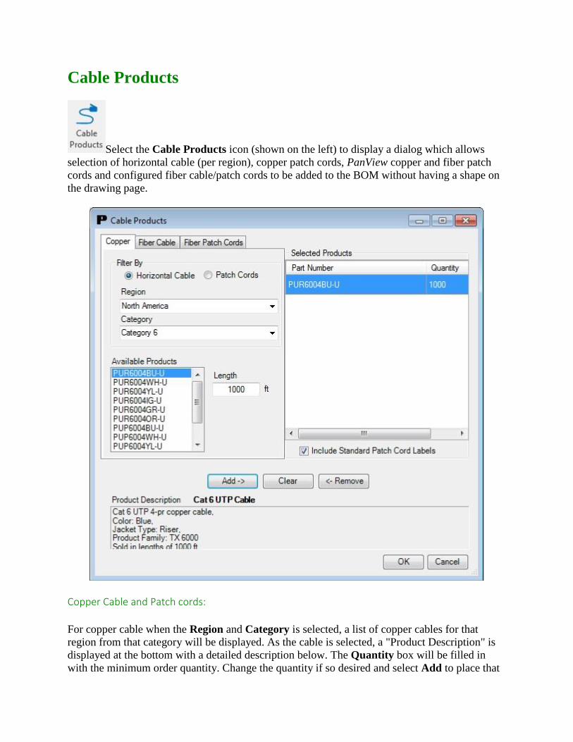
Cable Products
Select the Cable Products icon (shown on the left) to display a dialog which allows
selection of horizontal cable (per region), copper patch cords, PanView copper and fiber patch
cords and configured fiber cable/patch cords to be added to the BOM without having a shape on
the drawing page.
Copper Cable and Patch cords:
For copper cable when the Region and Category is selected, a list of copper cables for that
region from that category will be displayed. As the cable is selected, a "Product Description" is
displayed at the bottom with a detailed description below. The Quantity box will be filled in
with the minimum order quantity. Change the quantity if so desired and select Add to place that
item on the right side of the dialog box. Now it is to be stored for addition to the BOM once that
icon is selected.
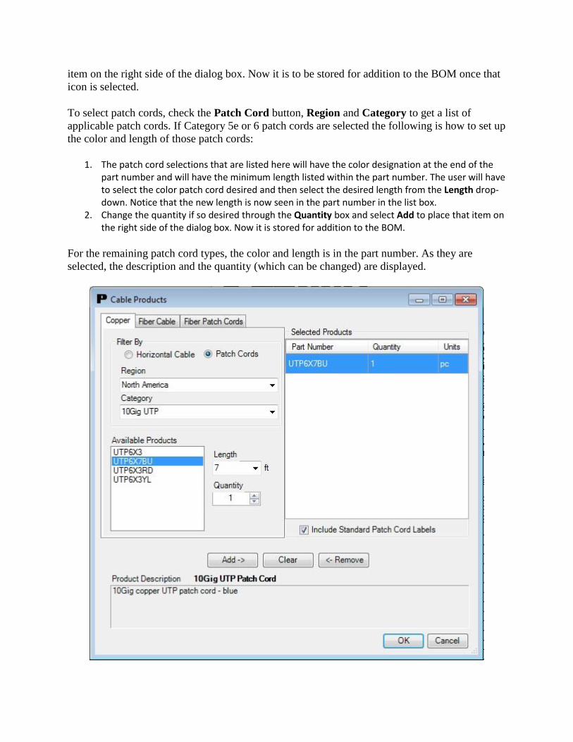
To select patch cords, check the Patch Cord button, Region and Category to get a list of
applicable patch cords. If Category 5e or 6 patch cords are selected the following is how to set up
the color and length of those patch cords:
1. The patch cord selections that are listed here will have the color designation at the end of the part number and will have the minimum length listed within the part number. The user will have to select the color patch cord desired and then select the desired length from the Length drop-down. Notice that the new length is now seen in the part number in the list box.
2. Change the quantity if so desired through the Quantity box and select Add to place that item on the right side of the dialog box. Now it is stored for addition to the BOM.
For the remaining patch cord types, the color and length is in the part number. As they are
selected, the description and the quantity (which can be changed) are displayed.

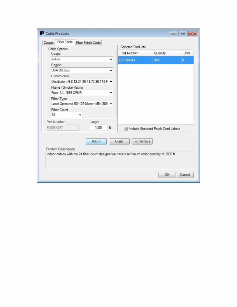
Fiber Cable and Patch cords:
To select the proper fiber cable and/or patch cords needed, go to the Fiber Cable and/or Fiber
Patch Cords tabs to use the configurator. By selecting an option via the drop down menus, you
will end up with a fiber cable or fiber patch cord part number and the minimum length or a
choice of lengths.
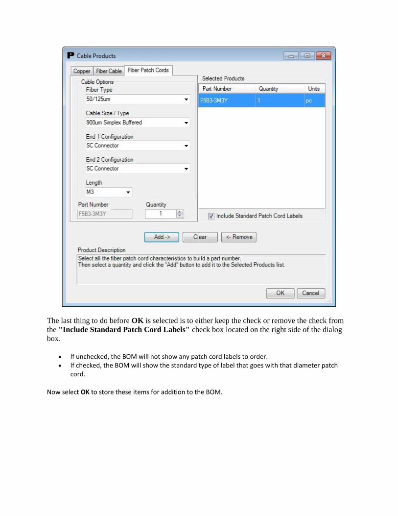
The last thing to do before OK is selected is to either keep the check or remove the check from
the "Include Standard Patch Cord Labels" check box located on the right side of the dialog
box.
If unchecked, the BOM will not show any patch cord labels to order. If checked, the BOM will show the standard type of label that goes with that diameter patch
cord.
Now select OK to store these items for addition to the BOM.
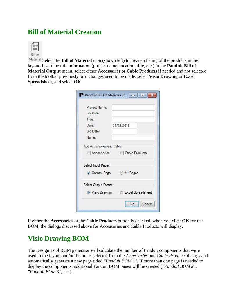
Bill of Material Creation
Select the Bill of Material icon (shown left) to create a listing of the products in the
layout. Insert the title information (project name, location, title, etc.) in the Panduit Bill of
Material Output menu, select either Accessories or Cable Products if needed and not selected
from the toolbar previously or if changes need to be made, select Visio Drawing or Excel
Spreadsheet, and select OK
If either the Accessories or the Cable Products button is checked, when you click OK for the
BOM, the dialogs discussed above for Accessories and Cable Products will display.
Visio Drawing BOM
The Design Tool BOM generator will calculate the number of Panduit components that were
used in the layout and/or the items selected from the Accessories and Cable Products dialogs and
automatically generate a new page titled "Panduit BOM 1". If more than one page is needed to
display the components, additional Panduit BOM pages will be created ("Panduit BOM 2",
"Panduit BOM 3", etc.).
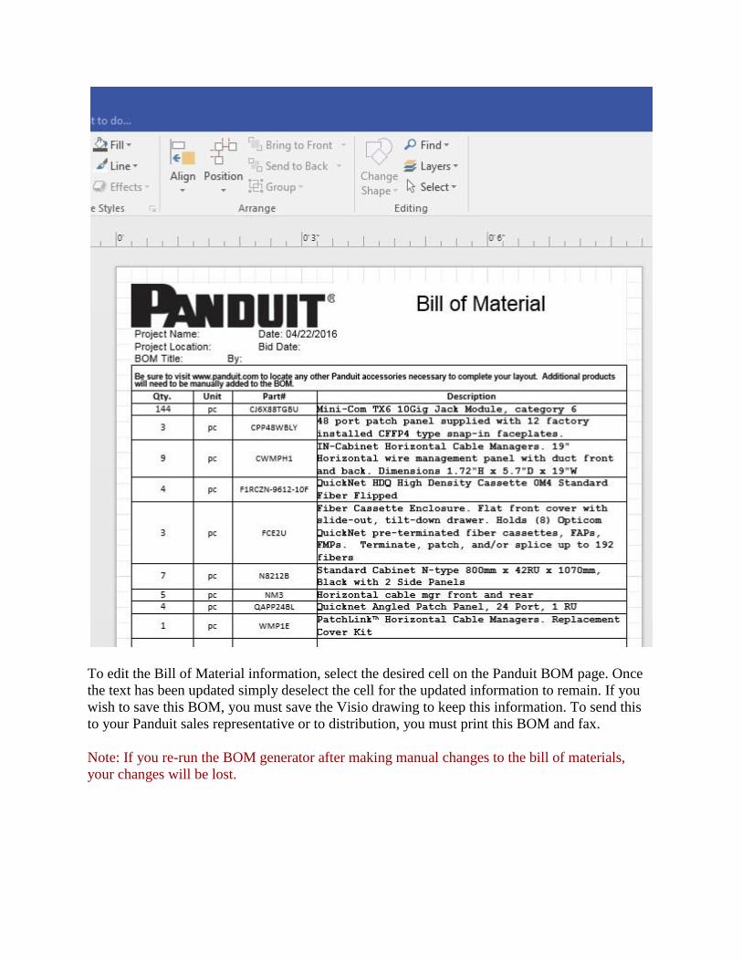
To edit the Bill of Material information, select the desired cell on the Panduit BOM page. Once
the text has been updated simply deselect the cell for the updated information to remain. If you
wish to save this BOM, you must save the Visio drawing to keep this information. To send this
to your Panduit sales representative or to distribution, you must print this BOM and fax.
Note: If you re-run the BOM generator after making manual changes to the bill of materials,
your changes will be lost.

Microsoft® Excel Spreadsheet BOM
The Bill of Material information can be organized in an Excel Spreadsheet by selecting the Excel
Spreadsheet output format at the bottom of the BOM dialog box.
Once the BOM in Excel format is displayed, editing is the done the same as any Excel
spreadsheet. Once the BOM is saved, separate from the Visio drawing, it can be printed and
faxed or emailed to your Panduit sales representative or distribution.
Note: The BOM generator uses an Excel file as a template to create the BOM layout. When saving the
file, use Save As... to give the file a new name.
Notes:
If Microsoft Excel is not installed on your system, the Excel Spreadsheet radio button in the Panduit Bill of Material Output dialog window will not be available for selection - it will be "grayed out."
The abbreviations in the Unit column stand for the following: o ft =foot o m = meter o pc = piece o pkg = package
Some part quantities are rounded up to the full piece. For example, since the channel sections come from the factory in 6’ lengths, 13.6 linear feet of channel would be rounded up to 18 feet on the BOM.

Ordering
To order the components listed on the Bill of Material, call your authorized Panduit distributor or
Panduit (800) 777-3300.
Note: Panduit Corporation assumes no obligation or liability for the accuracy of the Bill of
Material. It has been prepared to the best of our ability with the drawings and specifications
provided to us. All material and quantities should be verified by the installer. Applicable
components are shown to the nearest purchasable quantity.

Partner Information
Select the Visit Panduit Partners link (shown at the left, found by going to
Files > Panduit Design Tool for Visio) to be directed to the Partner Ecosystem page located on
Panduit’s website. This information will explain the Partner program and provide a list of
Partners whose websites can be accessed for other information or to access other Visio product
stencils.
Panduit Online
Select the Visit www.panduit.com link (shown at the left, found by going
to Files > Panduit Design Tool for Visio) to be directed to www.panduit.com. This will allow
access to all Panduit information at the click of the mouse.

Helpful Hints
For the FiberRunner™ product line, every junction whether it is channel-to-channel, fitting-to-fitting, or channel-to-fitting requires a QuikLock Coupler to join the components together.
The Fiber-Duct™ product line, every channel-to-channel junction requires the use of a coupler as well as the size appropriate Panduit Snap Rivets to secure the connection (refer to the Panduit catalog for the proper part numbers when ordering).
For the Fiber-Duct™ product line, every fitting-to-fitting and channel-to-fitting junction requires the use of the size appropriate Panduit Snap Rivets to secure the connection (refer to the Panduit catalog for the proper part numbers when ordering).
For the Data Center templates, our copper jack modules and fiber adapters, if there are various colors, once the part is brought onto the drawing, use the right mouse button for that part and chose the preferred color. The color and part number will change accordingly.
On a few occasions, when a part is brought onto the drawing to be placed on a rack, it is possible that the part will snap in on an angle. This part must be removed and the same part picked and brought onto the drawing and placed so the snap points fit correctly on the rack.
For a few fiber enclosures, FMT1 and FMT2, we show the product with the door closed. You can "snap" the enclosure into the rack, then "snap" the panel, which holds the fiber adapter panels, onto the enclosure, then "snap" the fiber adapter panels into the slots on the panel. That way, all products will be recognized by the Bill Of Material generator.
Please refer to the Panduit catalog and/or web site for additional part numbers and mounting options that may have not been included with this layout tool.
For the QUICKNET™ Fiber cassettes, the 12-fiber cassette shows one part number in the stencil, but when you drop that shape on the layout you can right mouse click and pick which part number you want in the BOM.
For the Net-Access™ Cabinets, the user can right mouse click and select the part number of the cabinet they need. For views other than Front, the user can Include or Not Include them in the BOM.
For the Top View shapes the user can right mouse click and Include or Not Include them in the BOM.
For the GridRunner™ and CabinetRunner shapes the user can right mouse click and Include or Not Include in the BOM.
Once a Panduit shape is placed on a drawing, you can right-click it and then click Panduit Part Info Online to open a web browser to the product page of the selected product shape.
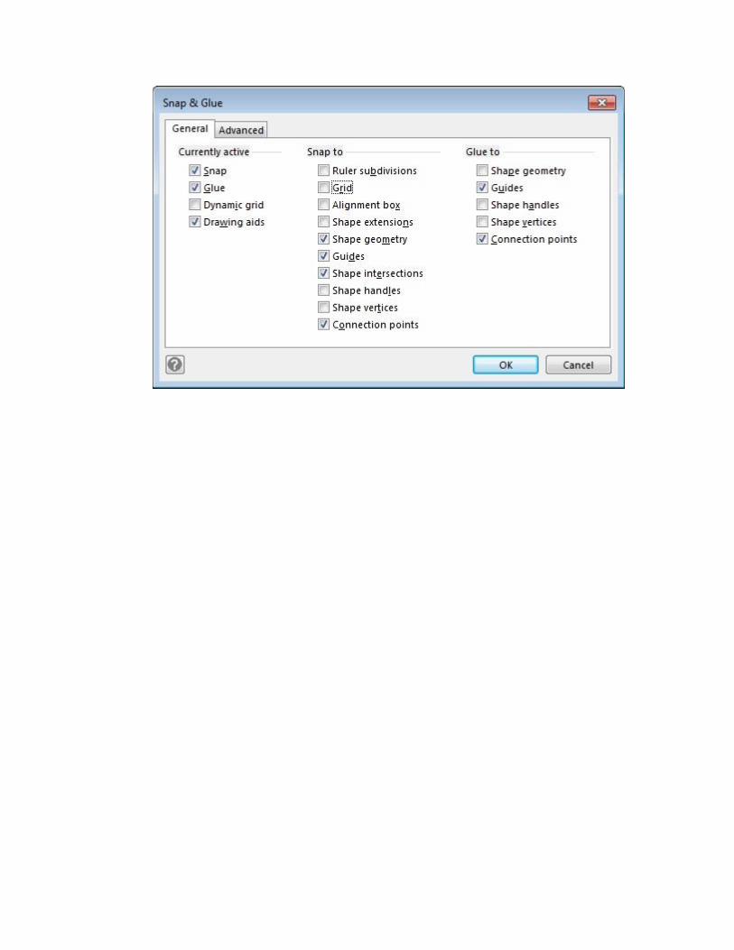
For the Wyr-Grid™ shapes, they can be most effectively used if the Visio snap settings are set the like the diagram below.

Shortcuts in Visio
Zoom In - Hit Ctrl and Shift at same time, Left mouse click (or rotate the scroll wheel). Zoom Out - Hit Ctrl and Shift at same time, Right mouse click (or rotate the scroll wheel). Zoom on particular area - Hit Ctrl and Shift at same time, use cursor (magnifying glass) to put a
box around area to zoom in on, release. Position shape not connected - Hold Shift and use up, down, left, right arrow to move shape into
correct location. Shape information:
o Custom Properties - Select the shape, right mouse click, then click View, Custom Properties.
o Group shapes together for an instance - Put cursor just outside upper left corner of shape and put box around all shapes you want to group. Once you release the box, all items are grouped for that instance. You can grab the group with the 4-headed arrow and move. Once you click anywhere on the page, the shapes are ungrouped.
o Group shapes together for as long as needed - Do as above to put a box around the shapes wanted in a group. Now, right mouse click, select Shape, and select Group. It will now be a group until you Ungroup the shapes.
o Sometimes to group them you may need to select one shape, then hold down the Ctrl key and select all the others. You may have to zoom in to selects all needed shapes. Then right mouse click, select Shape, and select Group.
Ungroup shapes - Select the group, right mouse click, select Shape, and select Ungroup.
All shapes are individual shapes again. Rotate or Flip shapes - Select shape, right mouse
click, select Shape, and select Rotate or Flip in whatever direction you need.
Groups - Remember, when shapes are grouped, they will not "snap" into place (i.e. On a rack). You can use the Shift/Arrow keys to move them into position. The BOM generator will find all the pieces of the group to list on the BOM.

Dialog Error Messages
If error messages are displayed when opening the Fill Calculator, Accessories, or Cable dialogs,
the underlying data file may have been deleted or corrupted. Check to make sure that
"C:\Program Files\Panduit Corporation\Panduit Design Tool For
Visio\CommonFiles\panduitDesignToolData.xml" exists and that you have permissions to read
it. If the file is missing, uninstall and reinstall the Panduit Visio Design Tool.
If some interruption occurred during the current session, the user may see a Visio error message
when selecting from the Panduit toolbar or the toolbar buttons will not work. Save the drawing,
close Visio, re-open Visio, open the drawing and the toolbar will be re-set.
Missing Panduit Menu or Stencil Navigator
The Panduit Menu and Stencil Navigator run as a COM Add-In. Click File->Options->Add-Ins
and then click the Go... button next to Manage: COM Add-Ins. Enable the check box next to the
"PanduitDataCenter" item and click OK.
Technical Support Info
For technical support call:
North America: 866-405-6654
Latin America: 01 800 969 42 00 or + 52 33 3777 6000
Europe, Middle East and Africa: 0044 (0) 208 6017251
Asia Pacific: 1800-PANDUIT (7263848)
Japan: +81-3-6863-6050
or email [email protected]

Copyright Notice
Copyright © 2016 Panduit Corp.
All Rights Reserved
Panduit Design Tool for Visio v6.0 User Manual
April 2016
Panduit Corporation
18900 Panduit Drive
Tinley Park, IL 60487
Liability Disclaimer
Panduit is not responsible for incorrectly ordered parts.
The software and this document are subject to change without notice.
Trademarks
Windows® is a registered trademark of Microsoft Corporation.
Visio® is a registered trademark of Microsoft Corporation.
Excel® is a registered trademark of Microsoft Corporation.
Panduit®, FiberRunner®, Mini-Com®, Opticom®, Pan-Punch®, and PanZone® are registered
trademarks of Panduit Corporation.
Fiber-Duct™, PatchRunner™, DP5e™, DP6™ Plus, GP6™ Plus, DataPatch™, GridRunner™,
PanView™, Net-Access™, QUICKNET™, and Cool Boot™ are trademarks of Panduit
Corporation.

Software License Agreement
PLEASE READ THIS SOFTWARE LICENSE AGREEMENT, ("LICENSE") CAREFULLY
BEFORE INSTALLING THIS SOFTWARE PRODUCT PROVIDED BY PANDUIT
CORPORATION, (“PANDUIT SOFTWARE”). BY PROCEEDING WITH THE
INSTALLATION OF THE PANDUIT SOFTWARE, YOU ARE AGREEING TO BE BOUND
BY THE TERMS OF THIS LICENSE. IF YOU DO NOT AGREE TO THE TERMS OF THIS
LICENSE, RETURN THE PANDUIT SOFTWARE TO THE PLACE WHERE YOU
OBTAINED IT.
License:
The Panduit software and documentation accompanying this License, whether on disk, in read
only memory, on CD-ROM, on a server, or on any other media or in any other form, are non-
exclusively licensed to you by Panduit Corp., and Panduit Corp. retains title, ownership rights,
and intellectual property rights in the Panduit software. The Panduit software, and any copies,
which this License authorizes you to make, is subject to this License.
Permitted Uses and Restrictions:
This License allows you to install and use the Panduit software on a single computer at a time.
This License does not allow the Panduit software to exist on more than one computer at a time,
except that you may make one (1) copy of the Panduit software in machine-readable form for
back-up purposes only. The back-up copy must include all copyright and proprietary information
contained in the original. Except as expressly permitted in this License, you may not decompile,
reverse engineer, disassemble, modify, adapt, translate, rent, lease, loan, sublicense, distribute or
create derivative works based upon the Panduit software, in whole or in part, or transmit the
Panduit software over a network. THE PANDUIT SOFTWARE IS NOT INTENDED FOR USE
IN HIGH-RISK ACTIVITIES, INCLUDING IN THE OPERATION OF NUCLEAR
FACILITIES, AIRCRAFT NAVIGATION OR COMMUNICATION SYSTEMS, OR AIR
TRAFFIC CONTROL MACHINES, IN WHICH CASE THE FAILURE OF THE PANDUIT
SOFTWARE COULD LEAD TO DEATH, PERSONAL INJURY, OR SEVERE PHYSICAL
OR ENVIRONMENTAL DAMAGE. Your rights under this License will terminate
automatically without notice from Panduit Corp. if you fail to comply with any terms of the
License. On termination, you must destroy all copies of the Panduit software.
No Warranties:
The Panduit software is distributed "AS IS" and without warranty of any kind, either express or
implied. The user assumes the entire risk as to the selection, results, and performance of the
software. In no event shall Panduit Corp. be liable, under any legal theory, for any damages
whatsoever, including lost profits, lost savings, lost or corrupted data, loss of goodwill, work
stoppage, computer malfunction, or other indirect, special, incidental or consequential damages
arising out of the use, the inability to use, or the failure of this software, even if Panduit Corp.
has been advised of the possibility of such damages. Implied warranties of merchantability and
fitness for a particular purpose and warranty of non-infringement are specifically disclaimed, as

are any and all other warranties, express or implied. Panduit Corp. does not warrant that the
functions contained in the Panduit software will meet your requirements, or that the operation of
the Panduit software will be uninterrupted or error-free, or that defects in the Panduit software
will be corrected. Furthermore, Panduit Corp. does not warrant or make any representations
regarding the use or the results of the use of the Panduit software or related documentation in
terms of their correctness, accuracy, reliability, or otherwise. Furthermore, no oral or written
information or advice given by Panduit Corp. or a Panduit Corp. authorized representative shall
create any warranties. Should the Panduit software prove defective, you (and not Panduit Corp.
or a Panduit Corp. authorized representative) assume the entire cost of all necessary servicing,
repair, or correction. The disclaimers of warranty constitute essential parts of this License.
SOME JURISDICTIONS DO NOT ALLOW EXCLUSIONS OF AN IMPLIED WARRANTY,
SO THIS DISCLAIMER MAY NOT APPLY TO YOU AND YOU MAY HAVE OTHER
LEGAL RIGHTS THAT VARY BY JURISDICTION.
Export Law Assurance:
You may not use, download, or otherwise export or re-export the Panduit software except as
authorized by United States Laws and the laws of the jurisdiction in which the Panduit software
was obtained. In particular, but without limitations, the Panduit software may not be exported or
re-exported (a) into (or to a national or resident of) any U.S. embargoed country or (b) to anyone
on the U.S. Treasury Department’s list of specifically designated nationals or the U.S.
Department of Commerce’s Table of Denial Orders. By downloading, installing, or using the
Panduit software, you represent and warrant that you are not located in, under control of, or a
national or resident of any such country or on any such list.
Controlling Law and Severability:
This License shall be governed by the laws of the United States and the State of Illinois. If for
any reason a court of competent jurisdiction finds any provision or portion thereof to be
unenforceable, the remainder of this License shall continue in full force and effect.
Complete Agreement:
This License constitutes the entire agreement between the parties with respect to the use of the
Panduit software and supersedes all prior or contemporaneous understandings regarding such
subject matter. No amendment to or modification of this License will be binding unless in
writing and signed by Panduit Corp.