pandora would like to thank you for choosing our dxl 1090l...
TRANSCRIPT
1USER MANUAL
Pandora DXL 1090L – is a premium car service-security system, built for cars with on-board voltage of 12V. It is a complex engineering solution which includes car security system, telemetry, remote and automatic engine start and various service options, all controlled from your OEM key remote, smartphone or online service.
When building Pandora DXL 1090L we were using the most up-to-date electronics from world’s best manufacturers. The device is built using high-precision mounting and control machinery, thus we guarantee highest possible quality, reliability and stable technical characteristics for the whole operation period.
Pandora DXL 1090L has a cryptographically strong authorization code with unique dialog algorithm and individual 128 bit encryption key on every device. We guarantee 100% protection form electronic hacking for the whole operation period.
The system is built for your convenience: it’s ergonomic, reliable, has the highest security and service characteristics. We are happy to provide any support we can – feel free to use our online support.
WARNING! It is strongly advised to have professional car mechanic installing the system. Any car electronics installer should be able to
install Pandora DXL 1090L using installation scheme in this manual and AlarmStudio software. Most features are highly dependent on competent installation. Our systems are thoroughly tested for quality, so if a feature fails to produce expected result, most likely the problem is in improper installation.
Pandora would like to thank you for choosing our DXL 1090L service and security system
32 USER MANUALPANDORA DXL 1090L SERVICE-SECURITY SYSTEM
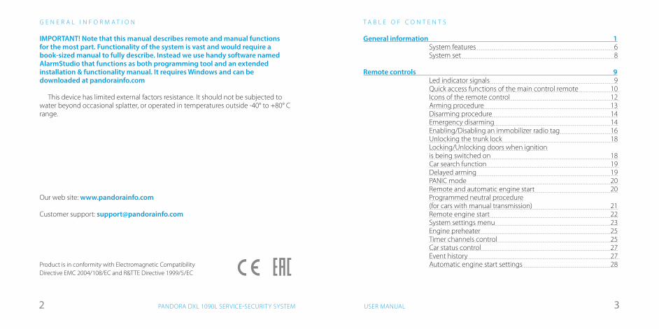
General information 1System features 6System set 8
Remote controls 9Led indicator signals 9Quick access functions of the main control remote 10 Icons of the remote control 12 Arming procedure 13Disarming procedure 14Emergency disarming 14Enabling/Disabling an immobilizer radio tag 16Unlocking the trunk lock 18Locking/Unlocking doors when ignitionis being switched on 18Car search function 19 Delayed arming 19PANIC mode 20 Remote and automatic engine start 20Programmed neutral procedure(for cars with manual transmission) 21Remote engine start 22System settings menu 23Engine preheater 25Timer channels control 25Car status control 27Event history 27 Automatic engine start settings 28
T A B L E O F C O N T E N T S
IMPORTANT! Note that this manual describes remote and manual functions for the most part. Functionality of the system is vast and would require a book-sized manual to fully describe. Instead we use handy software named AlarmStudio that functions as both programming tool and an extended installation & functionality manual. It requires Windows and can be downloaded at pandorainfo.com
This device has limited external factors resistance. It should not be subjected to water beyond occasional splatter, or operated in temperatures outside -40° to +80° C range.
Our web site: www.pandorainfo.com
Customer support: [email protected]
Product is in conformity with Electromagnetic Compatibility Directive EMC 2004/108/EC and R&TTE Directive 1999/5/EC
G E N E R A L I N F O R M A T I O N
54 USER MANUALPANDORA DXL 1090L SERVICE-SECURITY SYSTEM
T A B L E O F C O N T E N T S
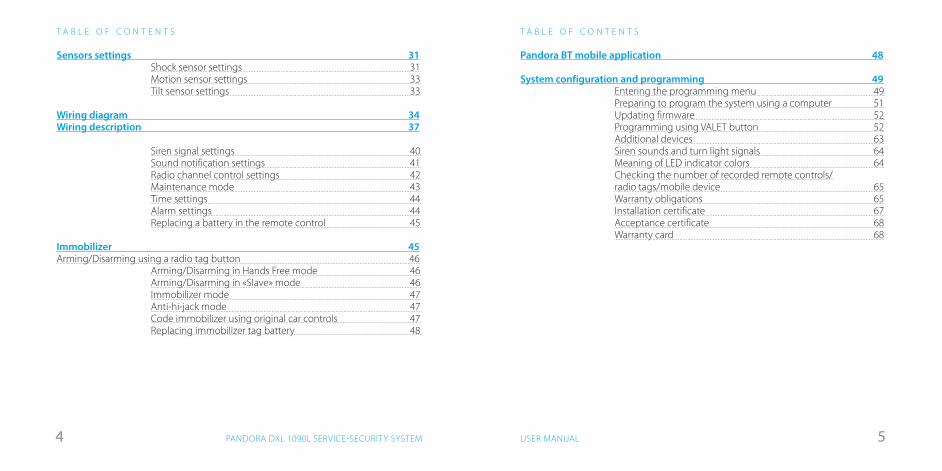
Pandora BT mobile application 48
System configuration and programming 49Entering the programming menu 49Preparing to program the system using a computer 51Updating firmware 52 Programming using VALET button 52Additional devices 63Siren sounds and turn light signals 64Meaning of LED indicator colors 64Checking the number of recorded remote controls/radio tags/mobile device 65Warranty obligations 65Installation certificate 67Acceptance certificate 68Warranty card 68
T A B L E O F C O N T E N T S
Sensors settings 31Shock sensor settings 31Motion sensor settings 33Tilt sensor settings 33
Wiring diagram 34Wiring description 37
Siren signal settings 40Sound notification settings 41Radio channel control settings 42Maintenance mode 43Time settings 44Alarm settings 44Replacing a battery in the remote control 45
Immobilizer 45Arming/Disarming using a radio tag button 46
Arming/Disarming in Hands Free mode 46Arming/Disarming in «Slave» mode 46Immobilizer mode 47Anti-hi-jack mode 47 Code immobilizer using original car controls 47Replacing immobilizer tag battery 48
76 USER MANUALPANDORA DXL 1090L SERVICE-SECURITY SYSTEM
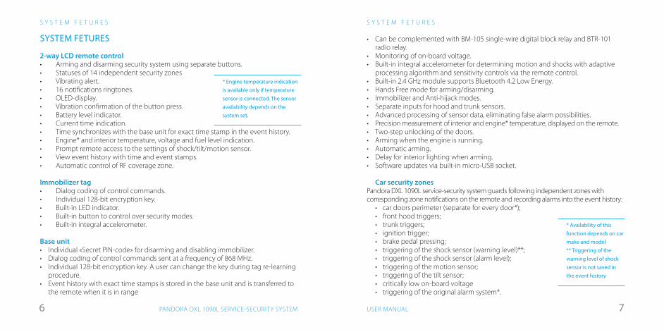
• Can be complemented with BM-105 single-wire digital block relay and BTR-101 radio relay.
• Monitoring of on-board voltage.• Built-in integral accelerometer for determining motion and shocks with adaptive
processing algorithm and sensitivity controls via the remote control.• Built-in 2.4 GHz module supports Bluetooth 4.2 Low Energy.• Hands Free mode for arming/disarming.• Immobilizer and Anti-hijack modes.• Separate inputs for hood and trunk sensors.• Advanced processing of sensor data, eliminating false alarm possibilities.• Precision measurement of interior and engine* temperature, displayed on the remote.• Two-step unlocking of the doors.• Arming when the engine is running.• Automatic arming.• Delay for interior lighting when arming.• Software updates via built-in micro-USB socket.
Car security zones
Pandora DXL 1090L service-security system guards following independent zones with corresponding zone notifications on the remote and recording alarms into the event history:
• car doors perimeter (separate for every door*);• front hood triggers;• trunk triggers;• ignition trigger;• brake pedal pressing;• triggering of the shock sensor (warning level)**;• triggering of the shock sensor (alarm level);• triggering of the motion sensor;• triggering of the tilt sensor;• critically low on-board voltage • triggering of the original alarm system*.
S Y S T E M F E T U R E S
* Availability of this function depends on car make and model ** Triggering of the warning level of shock sensor is not saved in the event history
S Y S T E M F E T U R E S
SYSTEM FETURES
2-way LCD remote control• Arming and disarming security system using separate buttons.• Statuses of 14 independent security zones• Vibrating alert.• 16 notifications ringtones.• OLED-display.• Vibration confirmation of the button press.• Battery level indicator.• Current time indication.• Time synchronizes with the base unit for exact time stamp in the event history.• Engine* and interior temperature, voltage and fuel level indication.• Prompt remote access to the settings of shock/tilt/motion sensor.• View event history with time and event stamps.• Automatic control of RF coverage zone.
Immobilizer tag• Dialog coding of control commands.• Individual 128-bit encryption key.• Built-in LED indicator.• Built-in button to control over security modes.• Built-in integral accelerometer.
Base unit• Individual «Secret PIN-code» for disarming and disabling immobilizer.• Dialog coding of control commands sent at a frequency of 868 MHz.• Individual 128-bit encryption key. A user can change the key during tag re-learning
procedure.• Event history with exact time stamps is stored in the base unit and is transferred to
the remote when it is in range
* Engine temperature indication is available only if temperature sensor is connected. The sensor availability depends on the system set.
98 USER MANUALPANDORA DXL 1090L SERVICE-SECURITY SYSTEM
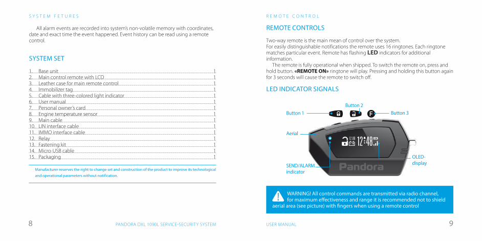
WARNING! All control commands are transmitted via radio channel, for maximum effectiveness and range it is recommended not to shield
aerial area (see picture) with fingers when using a remote control
REMOTE CONTROLS
Two-way remote is the main mean of control over the system.For easily distinguishable notifications the remote uses 16 ringtones. Each ringtone matches particular event. Remote has flashing LED indicators for additional information.
The remote is fully operational when shipped. To switch the remote on, press and hold button. «REMOTE ON» ringtone will play. Pressing and holding this button again for 3 seconds will cause the remote to switch off.
LED INDICATOR SIGNALS
R E M O T E C O N T R O L
Aerial
SEND/ALARMindicator
OLED-display
Button 1Button 2
Button 3
1212 0B 48
All alarm events are recorded into system’s non-volatile memory with coordinates, date and exact time the event happened. Event history can be read using a remote control.
SYSTEM SET
1. Base unit 12. Main control remote with LCD 13. Leather case for main remote control 14. Immobilizer tag 15. Cable with three-colored light indicator 1 6. User manual 17. Personal owner’s card 18. Engine temperature sensor 19. Main cable 110. LIN interface cable 111. IMMO interface cable 112. Relay 113. Fastening kit 114. Micro-USB cable 115. Packaging 1
Manufacturer reserves the right to change set and construction of the product to improve its technological and operational parameters without notification.
S Y S T E M F E T U R E S
1110 USER MANUALPANDORA DXL 1090L SERVICE-SECURITY SYSTEM
R E M O T E C O N T R O L
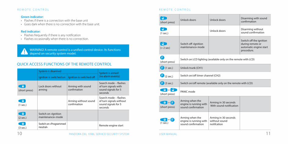
(short press)
Unlock doors Unlock doors Disarming with sound confirmation
(1 sec.)
Unlock doors Disarming without sound confirmation
(> 2 sec)Switch off «Ignition maintenance» mode
Switch off the ignition during remote or automatic engine start procedure.
(short press)
Switch on LCD lighting (available only on the remote with LCD)
(1 sec.) Unlock trunk (CH1)
(2 sec.) Switch on/off timer channel (CH2)
(3 sec.) Switch on/off remote (available only on the remote with LCD)
+ (short press)
PANIC mode
+ (short press)
Arming when the engine is running with sound confirmation
Arming in 30 seconds With sound notification
+ (1 sec.)
Arming when the engine is running with sound confirmation
Arming in 30 secondswithout sound notifcation
R E M O T E C O N T R O L
WARNING! A remote control is a unified control device. Its functions depend on security system model.
Green indicator:• Flashes if there is a connection with the base unit• Goes dark when there is no connection with the base unit.
Red indicator:• Flashes frequently if there is any notification• Flashes occasionally when there is no connection.
System is disarmedSystem is armed(no alarm events)Ignition is switched on Ignition is switched off
(short press)
Lock doors without arming
Arming with sound confrmation
Search mode – flashes of turn signals withsound signals for 5 seconds
(1 sec.)
Arming without sound confrmation
Search mode – flashes of turn signals withoutsound signals for 5 seconds
(2 sec.)
Switch on «Ignition maintenance» mode
(3 sec.)
Switch on «Programmed neutral» Remote engine start
QUICK ACCESS FUNCTIONS OF THE REMOTE CONTROL
1312 USER MANUALPANDORA DXL 1090L SERVICE-SECURITY SYSTEM
R E M O T E C O N T R O L
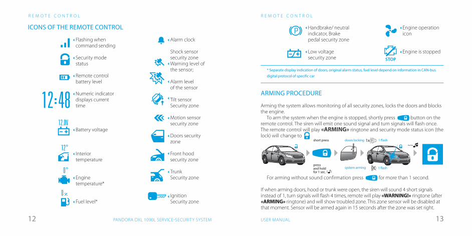
Handbrake/ neutral indicator, Brake pedal security zone
Low voltage security zone
P
ARMING PROCEDURE
Arming the system allows monitoring of all security zones, locks the doors and blocks the engine.
To arm the system when the engine is stopped, shortly press button on the remote control. The siren will emit one sound signal and turn signals will flash once. The remote control will play «ARMING» ringtone and security mode status icon (the lock) will change to
~~short press doors locking
system arming 1 �ash
1 �ash1x
pressand holdfor 1 sec.
* Separate display indication of doors, original alarm status, fuel level depend on information in CAN-bus digital protocol of specific car
For arming without sound confirmation press for more than 1 second.
If when arming doors, hood or trunk were open, the siren will sound 4 short signals instead of 1, turn signals will flash 4 times, remote will play «WARNING!» ringtone (after «ARMING» ringtone) and will show troubled zone. This zone sensor will be disabled at that moment. Sensor will be armed again in 15 seconds after the zone was set right.
Engine operation icon
Engine is stoppedSTOP
ICONS OF THE REMOTE CONTROL
R E M O T E C O N T R O L
Flashing when command sending
Security mode status
Remote control battery level
Numeric indicator displays current time
Battery voltage
Interior temperature
Enginetemperature*
Fuel level*
12 48
12°
0°
0
Alarm clock
Shock sensor security zoneWarning level of the sensor;
Alarm levelof the sensor
Tilt sensorSecurity zone
Motion sensor security zone
Doors security zone
Front hoodsecurity zone
TrunkSecurity zone
IgnitionSecurity zone
12.0V
1514 USER MANUALPANDORA DXL 1090L SERVICE-SECURITY SYSTEM
R E M O T E C O N T R O L
2-2-2-2
PIN
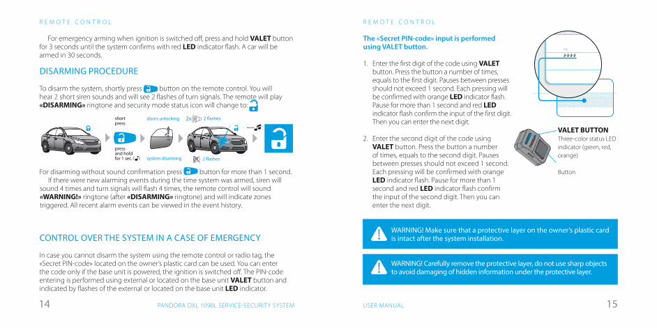
WARNING! Make sure that a protective layer on the owner’s plastic card is intact after the system installation.
WARNING! Carefully remove the protective layer, do not use sharp objects to avoid damaging of hidden information under the protective layer.
Three-color status LED indicator (green, red, orange)
Button
VALET BUTTON
The «Secret PIN-code» input is performed using VALET button.
1. Enter the first digit of the code using VALET button. Press the button a number of times, equals to the first digit. Pauses between presses should not exceed 1 second. Each pressing will be confirmed with orange LED indicator flash. Pause for more than 1 second and red LED indicator flash confirm the input of the first digit. Then you can enter the next digit.
2. Enter the second digit of the code using VALET button. Press the button a number of times, equals to the second digit. Pauses between presses should not exceed 1 second. Each pressing will be confirmed with orange LED indicator flash. Pause for more than 1 second and red LED indicator flash confirm the input of the second digit. Then you can enter the next digit.
R E M O T E C O N T R O L
For emergency arming when ignition is switched off, press and hold VALET button for 3 seconds until the system confirms with red LED indicator flash. A car will be armed in 30 seconds.
DISARMING PROCEDURE
To disarm the system, shortly press button on the remote control. You will hear 2 short siren sounds and will see 2 flashes of turn signals. The remote will play «DISARMING» ringtone and security mode status icon will change to:
For disarming without sound confirmation press button for more than 1 second.
~~
shortpress
pressand holdfor 1 sec.
doors unlocking
system disarming 2 �ashes
2 �ashes2x
If there were new alarming events during the time system was armed, siren will sound 4 times and turn signals will flash 4 times, the remote control will sound «WARNING!» ringtone (after «DISARMING» ringtone) and will indicate zones triggered. All recent alarm events can be viewed in the event history.
CONTROL OVER THE SYSTEM IN A CASE OF EMERGENCY
In case you cannot disarm the system using the remote control or radio tag, the «Secret PIN-code» located on the owner’s plastic card can be used. You can enter the code only if the base unit is powered, the ignition is switched off. The PIN-code entering is performed using external or located on the base unit VALET button and indicated by flashes of the external or located on the base unit LED indicator.
1716 USER MANUALPANDORA DXL 1090L SERVICE-SECURITY SYSTEM
R E M O T E C O N T R O L
To enable/disable a radio tag, enter level 15 (the system should be in programming mode). Enter the «Secret PIN-code» to disable radio tag or press VALET button once to enable radio tag.Enter the «Service PIN-code» to enter the programming mode (factory preset of the «Service PIN-code» is «1-1-1-1»). You can enter the code only if the base unit is powered, the ignition is switched off, the system is disarmed and the maintenance mode is switched off. If there is no «Service PIN-code», you can enter programming mode using the «Secret PIN-code» written on the owner’s card. After entering programming mode, press VALET button 15 times. Green color of LED indicator means a radio tag is switched on, red color means a radio tag is switched off.
Disabling a radio tag:LED indicator will light green after entering the programming level. The system will wait for entering the «Secret PIN-code». Enter the «Secret PIN-code» that is written on the owner’s plastic card. The system will confirm disabling of the radio tag with two sound signals of the siren and a long red LED flash. After that the system will return to the programming menu. If the PIN-code is not entered within 10 seconds or the input is incorrect, a siren will sound one signal, LED will produce the series of red and green flashes and the system will return to the programming menu.
Enabling a radio tag:LED indicator will light red after entering the programming level. The system will wait for action. Press VALET button once to enable radio tag. The system will confirm enabling with one short sound signal of a siren and a green LED light. After that the system will return to the programming menu.
R E M O T E C O N T R O L
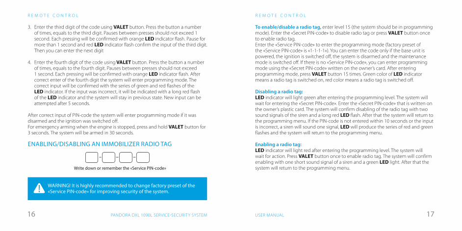
3. Enter the third digit of the code using VALET button. Press the button a number of times, equals to the third digit. Pauses between presses should not exceed 1 second. Each pressing will be confirmed with orange LED indicator flash. Pause for more than 1 second and red LED indicator flash confirm the input of the third digit. Then you can enter the next digit
4. Enter the fourth digit of the code using VALET button. Press the button a number of times, equals to the fourth digit. Pauses between presses should not exceed 1 second. Each pressing will be confirmed with orange LED indicator flash. After correct enter of the fourth digit the system will enter programming mode. The correct input will be confirmed with the series of green and red flashes of the LED indicator. If the input was incorrect, it will be indicated with a long red flash of the LED indicator and the system will stay in previous state. New input can be attempted after 5 seconds.
After correct input of PIN-code the system will enter programming mode if it was disarmed and the ignition was switched off. For emergency arming when the engine is stopped, press and hold VALET button for 3 seconds. The system will be armed in 30 seconds.
ENABLING/DISABLING AN IMMOBILIZER RADIO TAG
Write down or remember the «Service PIN-code»
WARNING! It is highly recommended to change factory preset of the «Service PIN-code» for improving security of the system.

1918 USER MANUALPANDORA DXL 1090L SERVICE-SECURITY SYSTEM
R E M O T E C O N T R O L
is switched off. There is an option in the settings that allows to prohibit automatic unlocking on switching off the ignition.
When using doors locking mode on the car movement start, the system will detect car moving and perform doors locking (it depends on motion sensor sensitivity settings).
When using doors locking mode when switching on the ignition, in no less than 5 seconds after the ignition was switched on, the doors will be locked automatically. If any door was opened after the ignition had been switched on, automatic locking will be disabled to prevent locking the keys inside the car.
CAR SEARCH FUNCTIONTo easily find your car on a massive parking, shortly press button when the car is armed. The system will sound the siren and flash turn signals 5 times in a row.
To search for car without sound confirmation, press and hold button for more than 1 second.
DELAYED ARMINGIf when leaving the car you cannot arm it using a remote control (you have your
hands full), you can use delayed arming.To activate this mode, shortly press and buttons simultaneously. LED
indicator will turn red, the system will lock doors and will arm in 30 seconds, the siren will sound and turn signals will flash once, indicating that the mode is triggered.
To activate this mode without sound confirmation, press and hold both and buttons for 1 second until the sound and vibration signal.
R E M O T E C O N T R O L
OFF
ONACC
doors locking
shortpress
doors unlocking
shortpress
5 �ashes
5 �ashes1x
pressand holdfor 1 sec.
UNLOCKING THE TRUNK To independently unlock the trunk, no matter if the system is armed or not, press button and hold it for 1 second.
If the system is armed when this action is performed, the trunk will be disarmed, shock and supplementary sensors will be disabled. All the other security zones will remain armed
If the trunk was not opened in 15 seconds after using «unlock trunk» command, the system will lock it again, enable sensors and arm trunk security zone. This will be indicated with 1 flash of turn signals.
LOCKING/UNLOCKING DOORS WHEN IGNITION IS BEING SWITCHED ONThe system controls doors locking when the engine is running. To lock doors, shortly press arming button, to unlock doors, press disarming.
There is an automatic movement lock mode that will lock the doors at the car movement or on switching on the ignition. Doors will be unlocked after the ignition
Pressand holdfor 1 sec.
2120 USER MANUALPANDORA DXL 1090L SERVICE-SECURITY SYSTEM
R E M O T E C O N T R O L
�xate the car usinga handbrake
leave the car, close the doors
OFF
ONACC
shortpress
«engine stop»ringtone
~~in 3 sec.,the engine will be stopped,the system is readyto perform remote start
R E M O T E C O N T R O L
PANIC MODEIf your car or you are in danger and you want to draw attention to your car, you can use PANIC mode. In this mode the siren will sound and turn signals will flash repeatedly for 30 seconds. To trigger PANIC mode, press и buttons simultaneously. To switch it off, press either или button.
REMOTE AND AUTOMATIC ENGINE STARTThe system allows for remote engine start using remote engine start command or automatic engine start using preconfigured automatic engine start function. Remote start can be used to heat engine and interior, charge battery or to cool the interior with air conditioning.
Remote and automatic start can only be used when the system is armed.If the car has manual transmission, remote or automatic start will only occur if
programmed neutral procedure was followed when the car was arming.Remote and automatic engine start on automatic transmission cars will only
occur, if transmission selector lever was left in a «P» position.When using remote and automatic engine start functions, make sure that the
car is secured with handbrake or some other means of fixating the car on a parking position.
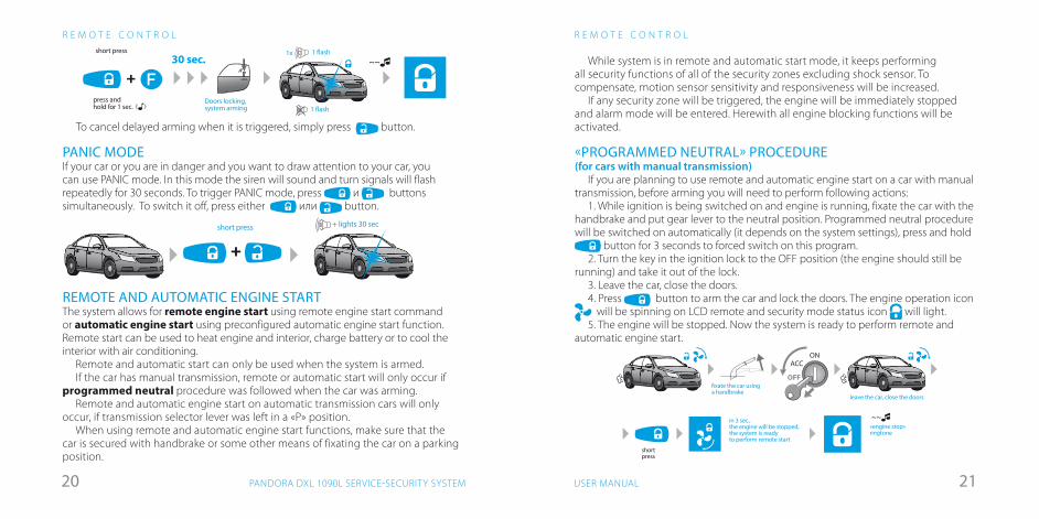
While system is in remote and automatic start mode, it keeps performing all security functions of all of the security zones excluding shock sensor. To compensate, motion sensor sensitivity and responsiveness will be increased.
If any security zone will be triggered, the engine will be immediately stopped and alarm mode will be entered. Herewith all engine blocking functions will be activated.
«PROGRAMMED NEUTRAL» PROCEDURE (for cars with manual transmission)
If you are planning to use remote and automatic engine start on a car with manual transmission, before arming you will need to perform following actions:
1. While ignition is being switched on and engine is running, fixate the car with the handbrake and put gear lever to the neutral position. Programmed neutral procedure will be switched on automatically (it depends on the system settings), press and hold
button for 3 seconds to forced switch on this program.2. Turn the key in the ignition lock to the OFF position (the engine should still be
running) and take it out of the lock.3. Leave the car, close the doors.4. Press button to arm the car and lock the doors. The engine operation icon will be spinning on LCD remote and security mode status icon will light.
5. The engine will be stopped. Now the system is ready to perform remote and automatic engine start.
short press + lights 30 sec
+
~~short press
Doors locking,system arming
1 �ash1x
press andhold for 1 sec. 1 �ash
30 sec.
+
To cancel delayed arming when it is triggered, simply press button.

2322 USER MANUALPANDORA DXL 1090L SERVICE-SECURITY SYSTEM
R E M O T E C O N T R O L
enginepreheater
12 480
enginepreheater:enabled
Enginepreheater:disabled
remote startsettings
systemcontrolsCHECK
channelcontrols
1 2 34 5 67 8 9
remote startsettings
systemcontrolsCHECK
channelcontrols
1 2 34 5 67 8 9
remote startsettings
systemcontrolsCHECK
channelcontrols
1 2 34 5 67 8 9
soundsdisabled
soundsenabled
sounds
sirensettings
sirensettings
sirensettings
sirensounds
SYSTEM SETTINGS MENU
Enter the main menu with button short press. To switch between menu sections shortly press button.
entering settings menu
• Control over engine preheater
• Control over timer channels
• Control over car status, view event history
• remote and automatic engine start adjusting
• sensors adjusting
• siren signals adjusting
sensorsadjusting
R E M O T E C O N T R O L
«Engine stop» ringtone
pressand holdfor 2 sec. engine stop~~
«Engine start»ringtone ~~
The remote will give notification 1 minute before designated engine stop: icon will flash and «engine stop in 1 minute» ringtone will play every 10 seconds.
Sending «Remote engine start» command will extend its operation period by 10minutes. This procedure can be repeated multiple times.
Engine operation duration depends on system settings – either heating time or threshold temperature for engine stop.
To remotely stop the engine while it performs heating, press and hold button for 2 or more seconds. The engine will be immediately stopped and it will be confirmed by remote playing «ENGINE STOP» ringtone and engine operation icon
fading.
REMOTE ENGINE START
If the system is prepared for remote start, to execute it, press and hold button for 3 seconds. Sound signal will confirm the command, LCD will show flashing engine operation icon signifying preparation to the engine start. In a few seconds the engine will be started, the remote will play «ENGINE START» ringtone and show spinning engine operation icon .
3 �ashes
«Engine start»ringtone
press and holdfor 3 sec.
preparingto start engine start ~~
2524 USER MANUALPANDORA DXL 1090L SERVICE-SECURITY SYSTEM
enginepreheater
12 480
enginepreheater:enabled
Enginepreheater:disabled
enginepreheater
12 480
enginepreheater:enabled
Enginepreheater:disabled
R E M O T E C O N T R O L
Preheater operation is disabled
Preheater operation is enabled
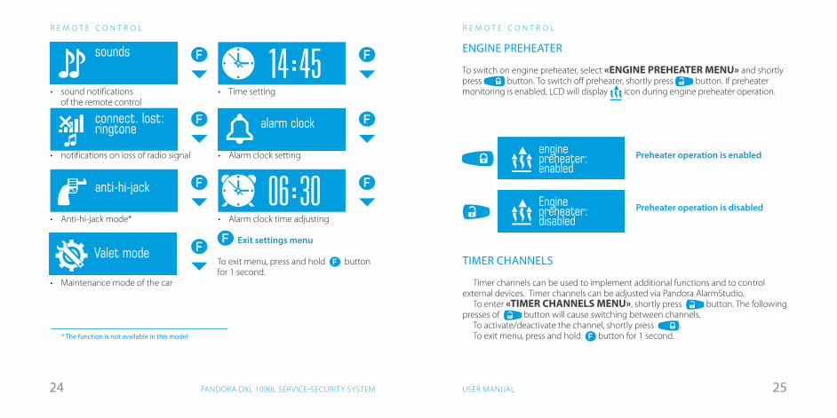
ENGINE PREHEATER
To switch on engine preheater, select «ENGINE PREHEATER MENU» and shortly press button. To switch off preheater, shortly press button. If preheater monitoring is enabled, LCD will display icon during engine preheater operation.
TIMER CHANNELS
Timer channels can be used to implement additional functions and to control external devices. Timer channels can be adjusted via Pandora AlarmStudio.
To enter «TIMER CHANNELS MENU», shortly press button. The following presses of button will cause switching between channels.
To activate/deactivate the channel, shortly press .To exit menu, press and hold button for 1 second.
R E M O T E C O N T R O L
* The function is not available in this model
• sound notifications of the remote control
• notifications on loss of radio signal
• Anti-hi-jack mode*
• Maintenance mode of the car
• Time setting
• Alarm clock setting
• Alarm clock time adjusting
Exit settings menu
To exit menu, press and hold button for 1 second.
valet modedisabled
Valet mode
valet modeenabled
14 4506 30
будильниквключен
будильниквыключен
будильник
soundsdisabled
soundsenabled
sounds
sirensettings
sirensettings
sirensettings
sirensounds
14 4506 30
alarm clockenabled
alarm clockdisabled
alarm clockconnect. lost:ringtone
connect. lost:alarm
connect. lost:no sound
anti-hi-jack
противоразбойвыключен
14 4506 30
будильниквключен
будильниквыключен
будильник
2726 USER MANUALPANDORA DXL 1090L SERVICE-SECURITY SYSTEM
R E M O T E C O N T R O L
27°24°12 0V0
systemcontrolsCHECK
27°24°12 0V0
systemcontrolsCHECK
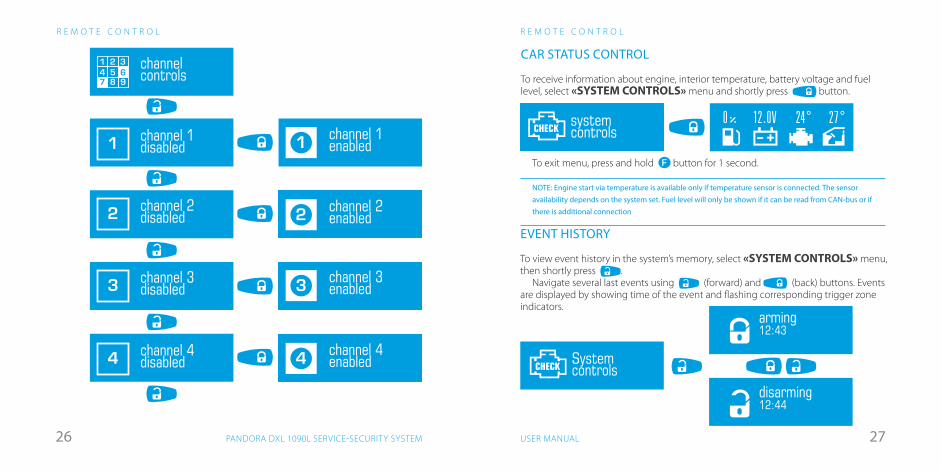
CAR STATUS CONTROL
To receive information about engine, interior temperature, battery voltage and fuel level, select «SYSTEM CONTROLS» menu and shortly press button.
To exit menu, press and hold button for 1 second.
NOTE: Engine start via temperature is available only if temperature sensor is connected. The sensor availability depends on the system set. Fuel level will only be shown if it can be read from CAN-bus or if there is additional connection
arming12:43
disarming12:44
SystemcontrolsCHECK
arming12:43
disarming12:44
SystemcontrolsCHECK
arming12:43
disarming12:44
SystemcontrolsCHECK
EVENT HISTORY
To view event history in the system’s memory, select «SYSTEM CONTROLS» menu, then shortly press .
Navigate several last events using (forward) and (back) buttons. Events are displayed by showing time of the event and flashing corresponding trigger zone indicators.
channelcontrols
1 2 34 5 67 8 9
1 channel 1disabled
2 channel 2disabled
3 channel 3disabled
4 channel 4disabled
1 channel 1enabled
2 channel 2enabled
3 channel 3enabled
4 channel 4enabled
channelcontrols
1 2 34 5 67 8 9
1 channel 1disabled
2 channel 2disabled
3 channel 3disabled
4 channel 4disabled
1 channel 1enabled
2 channel 2enabled
3 channel 3enabled
4 channel 4enabled
channelcontrols
1 2 34 5 67 8 9
1 channel 1disabled
2 channel 2disabled
3 channel 3disabled
4 channel 4disabled
1 channel 1enabled
2 channel 2enabled
3 channel 3enabled
4 channel 4enabled
channelcontrols
1 2 34 5 67 8 9
1 channel 1disabled
2 channel 2disabled
3 channel 3disabled
4 channel 4disabled
1 channel 1enabled
2 channel 2enabled
3 channel 3enabled
4 channel 4enabled
channelcontrols
1 2 34 5 67 8 9
1 channel 1disabled
2 channel 2disabled
3 channel 3disabled
4 channel 4disabled
1 channel 1enabled
2 channel 2enabled
3 channel 3enabled
4 channel 4enabled
channelcontrols
1 2 34 5 67 8 9
1 channel 1disabled
2 channel 2disabled
3 channel 3disabled
4 channel 4disabled
1 channel 1enabled
2 channel 2enabled
3 channel 3enabled
4 channel 4enabled
channelcontrols
1 2 34 5 67 8 9
1 channel 1disabled
2 channel 2disabled
3 channel 3disabled
4 channel 4disabled
1 channel 1enabled
2 channel 2enabled
3 channel 3enabled
4 channel 4enabled
channelcontrols
1 2 34 5 67 8 9
1 channel 1disabled
2 channel 2disabled
3 channel 3disabled
4 channel 4disabled
1 channel 1enabled
2 channel 2enabled
3 channel 3enabled
4 channel 4enabled
channelcontrols
1 2 34 5 67 8 9
1 channel 1disabled
2 channel 2disabled
3 channel 3disabled
4 channel 4disabled
1 channel 1enabled
2 channel 2enabled
3 channel 3enabled
4 channel 4enabled
R E M O T E C O N T R O L
2928 USER MANUALPANDORA DXL 1090L SERVICE-SECURITY SYSTEM
R E M O T E C O N T R O L
remote startsettings
send settings
startby timeenabled
startby timedisabled
daily startenabled
stop by tempenabled
daily startdisabled
stopby tempdisabled
startby tempenabled
startby tempdisabled
workduration20 min
start temp– 20°
stop temp80°
start time07:30
remote startsettings
send settings
startby timeenabled
startby timedisabled
daily startenabled
stop by tempenabled
daily startdisabled
stopby tempdisabled
startby tempenabled
startby tempdisabled
workduration20 min
start temp– 20°
stop temp80°
start time07:30
remote startsettings
send settings
startby timeenabled
startby timedisabled
daily startenabled
stop by tempenabled
daily startdisabled
stopby tempdisabled
startby tempenabled
startby tempdisabled
workduration20 min
start temp– 20°
stop temp80°
start time07:30
remote startsettings
send settings
startby timeenabled
startby timedisabled
daily startenabled
stop by tempenabled
daily startdisabled
stopby tempdisabled
startby tempenabled
startby tempdisabled
workduration20 min
start temp– 20°
stop temp80°
start time07:30
remote startsettings
send settings
startby timeenabled
startby timedisabled
daily startenabled
stop by tempenabled
daily startdisabled
stopby tempdisabled
startby tempenabled
startby tempdisabled
workduration20 min
start temp– 20°
stop temp80°
start time07:30
remote startsettings
send settings
startby timeenabled
startby timedisabled
daily startenabled
stop by tempenabled
daily startdisabled
stopby tempdisabled
startby tempenabled
startby tempdisabled
workduration20 min
start temp– 20°
stop temp80°
start time07:30
remote startsettings
send settings
startby timeenabled
startby timedisabled
daily startenabled
stop by tempenabled
daily startdisabled
stopby tempdisabled
startby tempenabled
startby tempdisabled
workduration20 min
start temp– 20°
stop temp80°
start time07:30
hours
increase
minutes
decrease
R E M O T E C O N T R O L
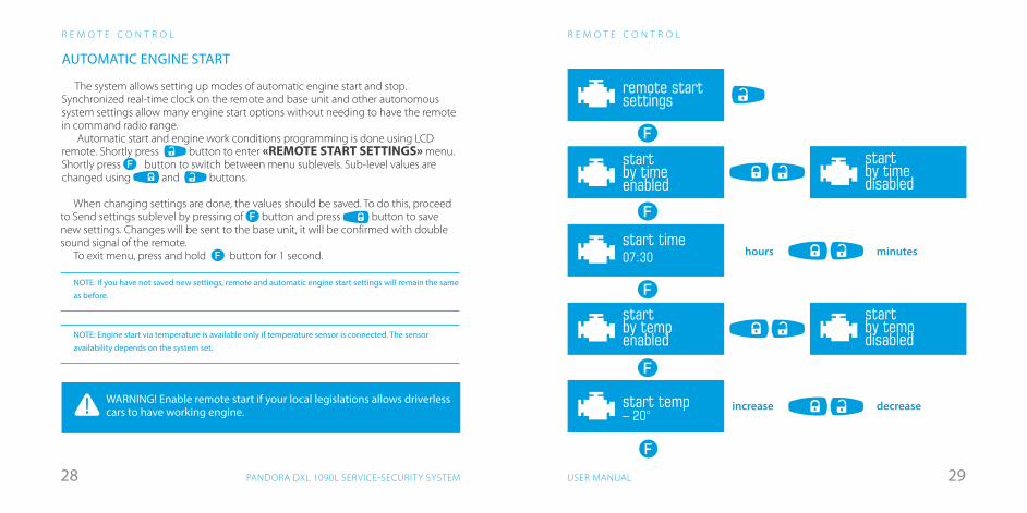
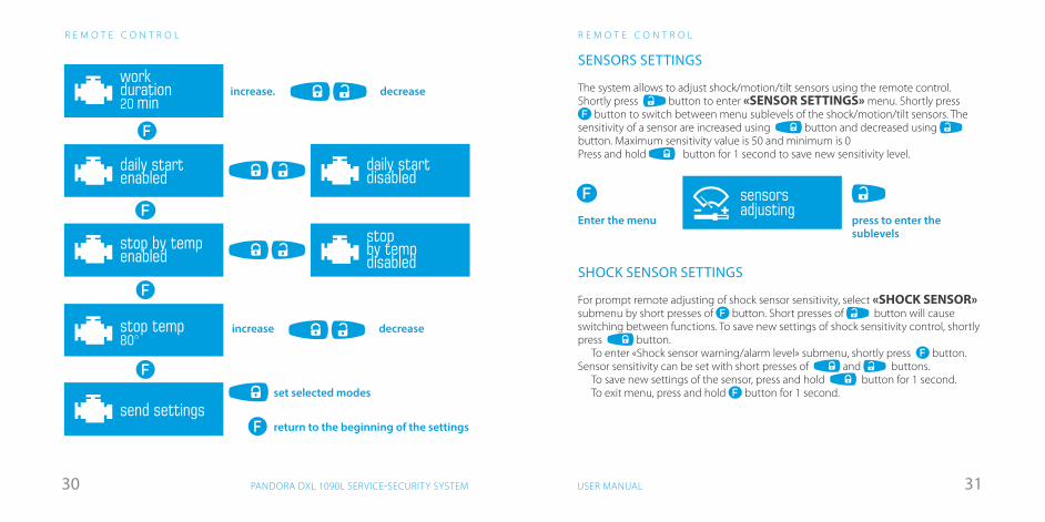
When changing settings are done, the values should be saved. To do this, proceed to Send settings sublevel by pressing of button and press button to save new settings. Changes will be sent to the base unit, it will be confirmed with double sound signal of the remote.
To exit menu, press and hold button for 1 second.
NOTE: If you have not saved new settings, remote and automatic engine start settings will remain the same as before.
NOTE: Engine start via temperature is available only if temperature sensor is connected. The sensor availability depends on the system set.
WARNING! Enable remote start if your local legislations allows driverless cars to have working engine.
AUTOMATIC ENGINE START
The system allows setting up modes of automatic engine start and stop. Synchronized real-time clock on the remote and base unit and other autonomous system settings allow many engine start options without needing to have the remote in command radio range.
Automatic start and engine work conditions programming is done using LCD remote. Shortly press button to enter «REMOTE START SETTINGS» menu. Shortly press button to switch between menu sublevels. Sub-level values are changed using and buttons.
3130 USER MANUALPANDORA DXL 1090L SERVICE-SECURITY SYSTEM
R E M O T E C O N T R O L
SENSORS SETTINGS
The system allows to adjust shock/motion/tilt sensors using the remote control.Shortly press button to enter «SENSOR SETTINGS» menu. Shortly press
button to switch between menu sublevels of the shock/motion/tilt sensors. The sensitivity of a sensor are increased using button and decreased using button. Maximum sensitivity value is 50 and minimum is 0Press and hold button for 1 second to save new sensitivity level.
SHOCK SENSOR SETTINGS
For prompt remote adjusting of shock sensor sensitivity, select «SHOCK SENSOR» submenu by short presses of button. Short presses of button will cause switching between functions. To save new settings of shock sensitivity control, shortly press button.
To enter «Shock sensor warning/alarm level» submenu, shortly press button. Sensor sensitivity can be set with short presses of and buttons.
To save new settings of the sensor, press and hold button for 1 second.To exit menu, press and hold button for 1 second.
sensorsadjusting
press to enter the sublevels
Enter the menu
remote startsettings
send settings
startby timeenabled
startby timedisabled
daily startenabled
stop by tempenabled
daily startdisabled
stopby tempdisabled
startby tempenabled
startby tempdisabled
workduration20 min
start temp– 20°
stop temp80°
start time07:30
R E M O T E C O N T R O L
increase. decrease
remote startsettings
send settings
startby timeenabled
startby timedisabled
daily startenabled
stop by tempenabled
daily startdisabled
stopby tempdisabled
startby tempenabled
startby tempdisabled
workduration20 min
start temp– 20°
stop temp80°
start time07:30
remote startsettings
send settings
startby timeenabled
startby timedisabled
daily startenabled
stop by tempenabled
daily startdisabled
stopby tempdisabled
startby tempenabled
startby tempdisabled
workduration20 min
start temp– 20°
stop temp80°
start time07:30
remote startsettings
send settings
startby timeenabled
startby timedisabled
daily startenabled
stop by tempenabled
daily startdisabled
stopby tempdisabled
startby tempenabled
startby tempdisabled
workduration20 min
start temp– 20°
stop temp80°
start time07:30
remote startsettings
send settings
startby timeenabled
startby timedisabled
daily startenabled
stop by tempenabled
daily startdisabled
stopby tempdisabled
startby tempenabled
startby tempdisabled
workduration20 min
start temp– 20°
stop temp80°
start time07:30
remote startsettings
send settings
startby timeenabled
startby timedisabled
daily startenabled
stop by tempenabled
daily startdisabled
stopby tempdisabled
startby tempenabled
startby tempdisabled
workduration20 min
start temp– 20°
stop temp80°
start time07:30
remote startsettings
send settings
startby timeenabled
startby timedisabled
daily startenabled
stop by tempenabled
daily startdisabled
stopby tempdisabled
startby tempenabled
startby tempdisabled
workduration20 min
start temp– 20°
stop temp80°
start time07:30
increase
return to the beginning of the settings
set selected modes
decrease
3332 USER MANUALPANDORA DXL 1090L SERVICE-SECURITY SYSTEM
R E M O T E C O N T R O L
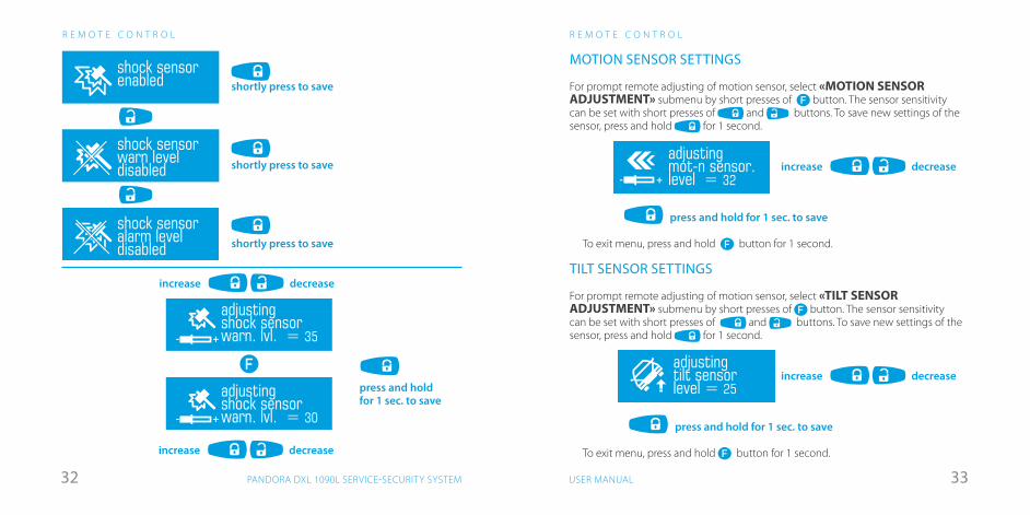
MOTION SENSOR SETTINGS
For prompt remote adjusting of motion sensor, select «MOTION SENSOR ADJUSTMENT» submenu by short presses of button. The sensor sensitivity can be set with short presses of and buttons. To save new settings of the sensor, press and hold for 1 second.
To exit menu, press and hold button for 1 second.
TILT SENSOR SETTINGS
For prompt remote adjusting of motion sensor, select «TILT SENSOR ADJUSTMENT» submenu by short presses of button. The sensor sensitivity can be set with short presses of and buttons. To save new settings of the sensor, press and hold for 1 second.
To exit menu, press and hold button for 1 second.
движение
регулировкадатчика движ.
adjustingmot-n sensor.level = 32
press and hold for 1 sec. to save
increase decrease
press and hold for 1 sec. to save
increase decrease
наклон
регулировкадатчика накл.
adjustingtilt sensorlevel = 25
R E M O T E C O N T R O L
датчик ударапредвар. уров.
shock sensorwarn leveldisabled
датчик ударапредвар. уров.включен
датчик ударатревож. уров.
датчик удара
датчик ударатревож. уров.включен
adjustingshock sensorwarn. lvl. = 35
adjustingshock sensorwarn. lvl. = 30
shock sensorenabled
доп. датчиквключен
доп. датчик
shock sensoralarm leveldisabled
shortly press to save
shortly press to save
shortly press to save
датчик ударапредвар. уров.
shock sensorwarn leveldisabled
датчик ударапредвар. уров.включен
датчик ударатревож. уров.
датчик удара
датчик ударатревож. уров.включен
adjustingshock sensorwarn. lvl. = 35
adjustingshock sensorwarn. lvl. = 30
shock sensorenabled
доп. датчиквключен
доп. датчик
shock sensoralarm leveldisabled
press and hold for 1 sec. to save
increase decrease
increase decrease
INP2 Doors trigger
DO
NO
T SH
IELD
BUIL
T-IN
AN
TEN
NA
!
micro-USB
ButtonVALET
X4
X6X7
X2
Pandora DXL
X1
X3
LOCAL INTERCONNECT NETWORKX1
X7
LIN inputLIN out
LIN driverof the system
Black2White1
LIN device
Sockets
X4 X5 X6 X7X3 X1
1
2
3
4
5
6
7
8 16
15
14
13
12
11
10
9
LIN connection For LADA cars (Kalina 2, Granta, Priora NEW,UAZ Patriot(05.2014)
Enginepreheater control
WebastoThermotop Evo, Eberspaecher Hydronic/Hidronic 2
LIN out1
X1
Tachometer input
CH5
CAN 2 - LCH2 - Close Central lock
CAN 1 - H
CAN 1 - L
CH3
CAN 2 - HCH4 - Open Central lock
CH1
INP4 Neutral/handbrake input
To turn signals
Ground
Siren
INP6 To ignition lock
INP3 Fronthood triggers
CH11
LOCAL INTERCONNECT NETWORKDoor
controlmodule
Driver’s door
LIN input
LIN out1
2X1
(-) 150mA
(-) 150mA
Enginetemperaturesensor
LEDindicator,VALETbutton
model: 1090 LX5
INP5 Brake trigger input/Fuel level input
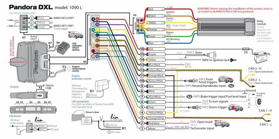
WARNING! Before starting the installation of the system, select a car model in ALARMSTUDIO (CAN-bus protocol)
Open trunk
For remote engine start
White2
IMMO-KEY2/INP7 Black3
IMMO-KEY1/INP1Trunk triggerGreen1
Relaymodule(wiringdiagram is onthe next page,the moduleis not shippedwith the system)
3 6
52
1 4
+ 12V
StarterCH10
BypassCH8
NO BlockingCH7
АСС / Brake Pedal*CH6
IgnitionCH9
Brown (–)
Yellow
Yellow
(–)
Orange (–)
Green
Green
Gray
(–)
Blue
Blue
Blue/Black
Blue/White
Yellow/Black
Yellow/White
Orange/Black
Orange/White
White
Black
Brown/White
Red/Black
Purple
(–)
Red
Red
(+)
Battery12 V
To originalwiring
(Uamp3..100V, min 8Hz)
37USER MANUAL
W I R I N G D E S C R I P T I O N • W I R I N G D I A G R A M
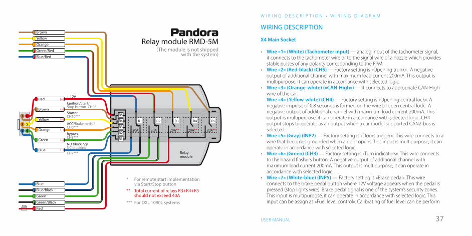
PandoraRelay module RMD-5M
(The module is not shippedwith the system)
** Total current of relays R3+R4+R5 should not exceed 40А*** For DXL 1090L systems
* For remote start implementation via Start/Stop button
3 6
52
1 4
+ 12V
StarterCH10***
BypassCH8***
NO blocking/NC blockingCH7***
ACC/Brake pedal*CH6***
Ignition/Start/Stop button CH9*
R4
R5
R3
R2
R1
R1 R2 R3 R4 R5
20A**20A**20A**20A20A
Relaymodule
Brown
Yellow
Orange
Green/Red
Blue/Red
40А
Blue
Blue/Black
Green
Green/Black
Red
Brown (–)
Yellow (–)
Orange (–)
Green (–)
Blue (–)
Red (+)
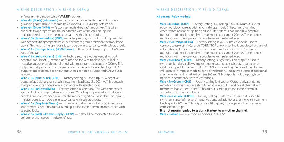
WIRING DESCRIPTION
Х4 Main Socket
• Wire «1» (White) (Tachometer input) — analog input of the tachometer signal, it connects to the tachometer wire or to the signal wire of a nozzle which provides stable pulses of any polarity corresponding to the RPM.
• Wire «2» (Red-black) (CH5) — Factory setting is «Opening trunk». A negative output of additional channel with maximum load current 200mA. This output is multipurpose, it can operate in accordance with selected logic.
• Wire «3» (Orange-white) («CAN-High») — It connects to appropriate CAN-High wire of the car. Wire «4» (Yellow-white) (СН4) — Factory setting is «Opening central lock». A negative impulse of 0,8 seconds is formed on the wire to open central lock. A negative output of additional channel with maximum load current 200mA. This output is multipurpose, it can operate in accordance with selected logic. CH4 output stops to operate as an output when a car model supported CAN2-bus is selected.
• Wire «5» (Gray) (INP2) — Factory setting is «Doors trigger». This wire connects to a wire that becomes grounded when a door opens. This input is multipurpose, it can operate in accordance with selected logic.
• Wire «6» (Green) (СН3) — Factory setting is «Turn indicators». This wire connects to the hazard flashers button. A negative output of additional channel with maximum load current 200mA. This output is multipurpose; it can operate in accordance with selected logic.
• Wire «7» (White-blue) (INP5) — Factory setting is «Brake pedal». This wire connects to the brake pedal button where 12V voltage appears when the pedal is pressed (stop lights wire). Brake pedal signal is one of the system’s security zones. This input is multipurpose, it can operate in accordance with selected logic. This input can be assign as «Fuel level control». Calibrating of fuel level can be perform
3938 USER MANUALPANDORA DXL 1090L SERVICE-SECURITY SYSTEM
Х5 socket (Relay module)
• Wire «1» (Blue) (CH7) — Factory setting is «Blocking N.O.» This output is used to control blocking relay with a normally open logic (it becomes grounded when switching on the ignition and security system is not armed). A negative output of additional channel with maximum load current 200mA. This output is multipurpose, it can operate in accordance with selected logic.
• Wire «2» (Orange) (CH6) — Factory setting is «ACC». The channel is used to control accessories. If «Car with START/STOP button» setting is enabled, the channel will control brake pedal during remote or automatic engine start. A negative output of additional channel with maximum load current 200mA. This output is multipurpose, it can operate in accordance with selected logic.
• Wire «3» (Brown) (CH9) — Factory setting is «Ignition». This output is used to switch on ignition. It allows implementing automatic engine start, turbo timer, ignition support. If «Car with START/STOP button» setting is enabled, the channel will operate in impulse mode to control the button. A negative output of additional channel with maximum load current 200mA. This output is multipurpose, it can operate in accordance with selected logic.
• Wire «4» (Green) (CH8) — Factory setting is «Bypass». Output activates during remote or automatic engine start. A negative output of additional channel with maximum load current 200mA. This output is multipurpose, it can operate in accordance with selected logic
• Wire «5» (Yellow) (CH10) — Factory setting is «Starter». This output is used to switch on starter of the car. A negative output of additional channel with maximum load capacity 200mA. This output is multipurpose, it can operate in accordance with selected logic. It is not recommended to assign «Starter» to any other channel.
• Wire «6» (Red) — relay module power supply 12V
W I R I N G D E S C R I P T I O N • W I R I N G D I A G R A M
in Programming mode using «VALET» button. • Wire «8» (Black) («Ground») — It should be connected to the car body in a
grounding spot. This wire should be connected FIRST during installation.• Wire «9» (Blue) (INP4) — Factory setting is «Neutral/Handbrake». This wire
connects to appropriate neutral/handbrake wire of the car. This input is multipurpose, it can operate in accordance with selected logic.
• Wire «10» (Brown-white) (INP3) — Factory setting is «Front hood trigger». This wire connects to appropriate wire that becomes grounded when the front hood opens. This input is multipurpose, it can operate in accordance with selected logic.
• Wire «11» (Orange-black) («CAN-Low») — It connects to appropriate CAN-Low wire of the car.
• Wire «12» (Yellow-black) (СН2) — Factory setting is «Close central lock». A negative impulse of 0,8 seconds is formed on the wire to close central lock. A negative output of additional channel with maximum load capacity 200mA. This output is multipurpose, it can operate in accordance with selected logic. CH2 output stops to operate as an output when a car model supported CAN2-bus is selected.
• Wire «13» (Blue-black) (CH1) — Factory setting is «Free output». A negative output of additional channel with maximum load capacity 200mA. This output is multipurpose, it can operate in accordance with selected logic.
• Wire «14» (Yellow) (INP6) — Factory setting is «Ignition». This wire connects to ignition lock or to appropriate wire where 12V voltage appears when ignition is enabled and doesn’t disappear until the moment ignition is disabled. This input is multipurpose, it can operate in accordance with selected logic.
• Wire «15» (Purple) («Siren») — It connects to siren control wire (+) (maximum load current is 2A). This output is multipurpose, it can operate in accordance with selected logic.
• Wire «16» (Red) («Power supply» +12V) — It should be connected to reliable conductor with constant voltage of 12V.
W I R I N G D E S C R I P T I O N • W I R I N G D I A G R A M
4140 USER MANUALPANDORA DXL 1090L SERVICE-SECURITY SYSTEM
R E M O T E C O N T R O L
soundsdisabled
soundsenabled
sounds
sirensettings
sirensettings
sirensettings
sirensounds
soundsdisabled
soundsenabled
sounds
sirensettings
sirensettings
sirensettings
sirensounds
soundsdisabled
soundsenabled
sounds
sirensettings
sirensettings
sirensettings
sirensounds
all sound signals are enabled
warning signals are disabled
warning and alarm signals are disabled
shortly press to save
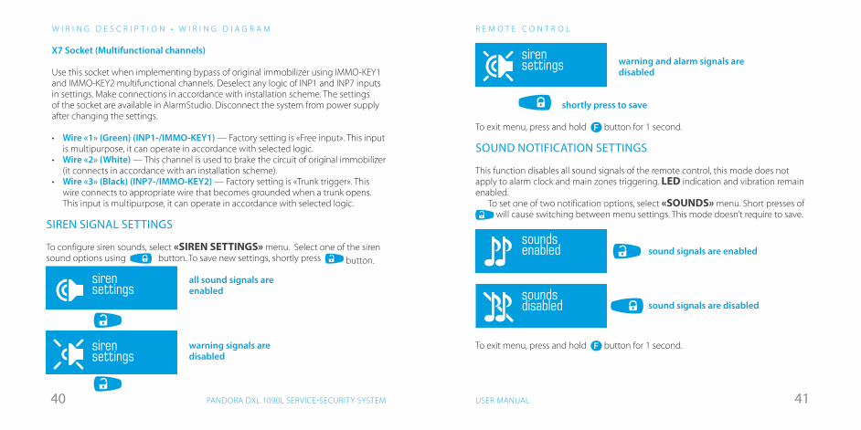
SIREN SIGNAL SETTINGS
To configure siren sounds, select «SIREN SETTINGS» menu. Select one of the siren sound options using button. To save new settings, shortly press button.
To exit menu, press and hold button for 1 second.
SOUND NOTIFICATION SETTINGS
This function disables all sound signals of the remote control, this mode does not apply to alarm clock and main zones triggering. LED indication and vibration remain enabled.
To set one of two notification options, select «SOUNDS» menu. Short presses of will cause switching between menu settings. This mode doesn’t require to save.
To exit menu, press and hold button for 1 second.
Х7 Socket (Multifunctional channels)
Use this socket when implementing bypass of original immobilizer using IMMO-KEY1 and IMMO-KEY2 multifunctional channels. Deselect any logic of INP1 and INP7 inputs in settings. Make connections in accordance with installation scheme. The settings of the socket are available in AlarmStudio. Disconnect the system from power supply after changing the settings.
• Wire «1» (Green) (INP1-/IMMO-KEY1) — Factory setting is «Free input». This input is multipurpose, it can operate in accordance with selected logic.
• Wire «2» (White) — This channel is used to brake the circuit of original immobilizer (it connects in accordance with an installation scheme).
• Wire «3» (Black) (INP7-/IMMO-KEY2) — Factory setting is «Trunk trigger». This wire connects to appropriate wire that becomes grounded when a trunk opens. This input is multipurpose, it can operate in accordance with selected logic.
W I R I N G D E S C R I P T I O N • W I R I N G D I A G R A M
soundsdisabled
soundsenabled
sounds
sirensettings
sirensettings
sirensettings
sirensounds
soundsdisabled
soundsenabled
sounds
sirensettings
sirensettings
sirensettings
sirensounds
sound signals are enabled
sound signals are disabled
4342 USER MANUALPANDORA DXL 1090L SERVICE-SECURITY SYSTEM
R E M O T E C O N T R O L
«Connection lost» ringtonenotification
alarm signal
all notification are disabled
connect. lost:ringtone
connect. lost:alarm
connect. lost:no sound
connect. lost:ringtone
connect. lost:alarm
connect. lost:no sound
connect. lost:ringtone
connect. lost:alarm
connect. lost:no sound
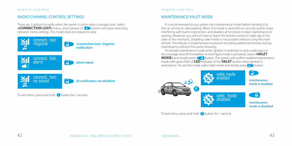
MAINTENANCE/VALET MODE
It is recommended to put system into maintenance mode before handing it to the car service or valet parking. When this mode is switched on, security system stops interfering with built-in electronics and disables all functions to ease maintenance or parking. Moreover, you will not have to leave the remote control or radio tag to the valet or the mechanic. Disabling valet mode is not possible without using the main remote. This feature is implemented to prevent recording additional remotes during maintenance without the owner knowing.
To activate maintenance mode when ignition is switched on and a radio tag is in the coverage zone (if Immobilizer or Anti-hijack mode is activated), select «VALET MODE» and shortly press button. The system will confirm enabled maintenance mode with green flash of LED indicator of the VALET button when ignition is switched on. To exit this mode, select Valet mode and shortly press button.
R E M O T E C O N T R O L
RADIO CHANNEL CONTROL SETTINGS
There are 3 options to notify when the owner is not in radio coverage zone. Select «CONNECTION LOST» menu, short presses of button will cause switching between menu settings. This mode does not require to save.
To exit menu, press and hold button for 1 second.
valet modedisabled
Valet mode
valet modeenabled
valet modedisabled
Valet mode
valet modeenabled
Надежно зафиксируйтеавтомобиль ручным тормозом Покиньте автомобиль,
закройте двери
OFF
ONACC
нажмитекоротко
Звучит мелодия«останов двигателя»
~~Через 3 сек. двигательбудет остановлен, система готова к дистанционному запуску
maintenance mode is disabled
maintenance mode is enabled
To exit menu, press and hold button for 1 second.
4544 USER MANUALPANDORA DXL 1090L SERVICE-SECURITY SYSTEM
R E M O T E C O N T R O L • I M M O B I L I Z E R14 4506 30
будильниквключен
будильниквыключен
будильник
14 4506 30
alarm clockenabled
alarm clockdisabled
alarm clock
14 4506 30
alarm clockenabled
alarm clockdisabled
alarm clock
hours minutes
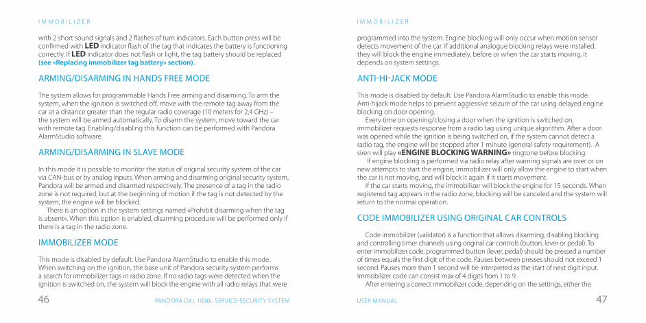
ALARM CLOCK SETTINGS
To set up the alarm clock, select «ALARM CLOCK» menu. Enable alarm with short press of button or disable it with short press of button.
Setting of alarm clock is similar to clock setting.
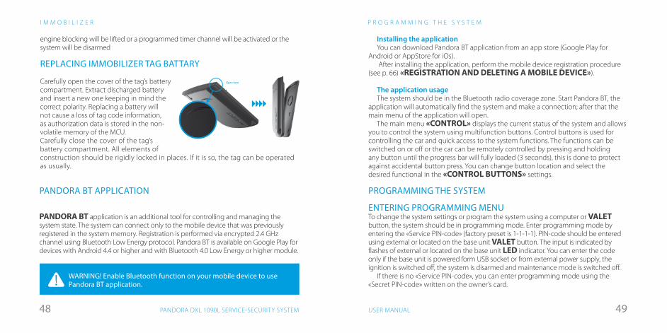
REPLACING A BATTERY IN THE REMOTE CONTROL
If high quality batteries are used, service-security system remote can function up to 4 months without needing a replacement. Battery needs to be replaced if the remote control is not turning on or the icon has only one bar left and starts flashing. To replace the battery:• move battery cover lock in the direction shown with
arrow;• take the battery out and place a new one on its place;• the remote is ready for use (switch it on by pressing and
holding button for 3 seconds)It is recommended to keep an extra AAA battery
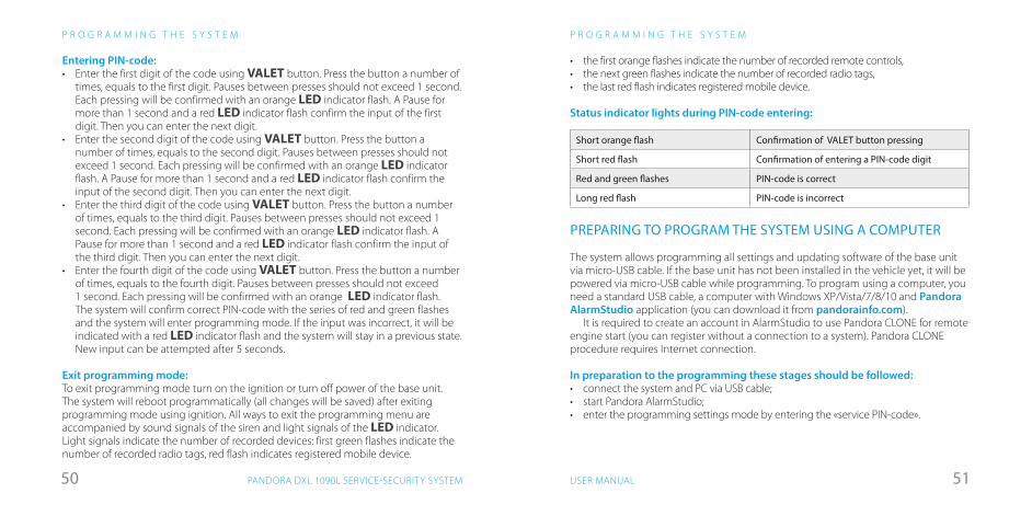
ARMING/DISARMING USING A RADIO TAG
To arm/disarm the system, RF tag should be in radio coverage area. The system produces a protected (AES-128 encryption) interactive high-speed exchange of authorization codes in the frequency range 2,4 GHz on one of 125 channels. To arm the system when the ignition is switched off, shortly press the tag button. The system will confirm the command receiving with 1 short sound signal and 1 flash of turn indicators.To disarm the system, shortly press the tag button. The system will confirm the command receiving
R E M O T E C O N T R O L
14 4506 30
будильниквключен
будильниквыключен
будильник
hours minutes
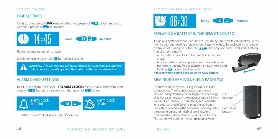
TIME SETTINGS
To set up time, select «TIME» menu. With short presses of button set hours, with short presses of set minutes.
This mode does not require to save
To exit menu, press and hold button for 1 second.
WARNING! The system time will be automatically synchronized with the mobile device time after pairing the system with the mobile device.
LED indicator
Controlling button
4746 USER MANUALPANDORA DXL 1090L SERVICE-SECURITY SYSTEM
programmed into the system. Engine blocking will only occur when motion sensor detects movement of the car. If additional analogue blocking relays were installed, they will block the engine immediately, before or when the car starts moving, it depends on system settings.
ANTI-HI-JACK MODE
This mode is disabled by default. Use Pandora AlarmStudio to enable this mode. Anti-hijack mode helps to prevent aggressive seizure of the car using delayed engine blocking on door opening.
Every time on opening/closing a door when the ignition is switched on, immobilizer requests response from a radio tag using unique algorithm. After a door was opened while the ignition is being switched on, if the system cannot detect a radio tag, the engine will be stopped after 1 minute (general safety requirement). A siren will play «ENGINE BLOCKING WARNING» ringtone before blocking.
If engine blocking is performed via radio relay after warning signals are over or on new attempts to start the engine, immobilizer will only allow the engine to start when the car is not moving, and will block it again if it starts movement.
If the car starts moving, the immobilizer will block the engine for 15 seconds. When registered tag appears in the radio zone, blocking will be canceled and the system will return to the normal operation.
CODE IMMOBILIZER USING ORIGINAL CAR CONTROLS
Code immobilizer (validator) is a function that allows disarming, disabling blocking and controlling timer channels using original car controls (button, lever or pedal). To enter immobilizer code, programmed button (lever, pedal) should be pressed a number of times equals the first digit of the code. Pauses between presses should not exceed 1 second. Pauses more than 1 second will be interpreted as the start of next digit input. Immobilizer code can consist max of 4 digits from 1 to 9.
After entering a correct immobilizer code, depending on the settings, either the
I M M O B I L I Z E RI M M O B I L I Z E R
with 2 short sound signals and 2 flashes of turn indicators. Each button press will be confirmed with LED indicator flash of the tag that indicates the battery is functioning correctly. If LED indicator does not flash or light, the tag battery should be replaced (see «Replacing immobilizer tag battery» section).
ARMING/DISARMING IN HANDS FREE MODE
The system allows for programmable Hands Free arming and disarming. To arm the system, when the ignition is switched off, move with the remote tag away from the car at a distance greater than the regular radio coverage (10 meters for 2,4 GHz) – the system will be armed automatically. To disarm the system, move toward the car with remote tag. Enabling/disabling this function can be performed with Pandora AlarmStudio software.
ARMING/DISARMING IN SLAVE MODE
In this mode it is possible to monitor the status of original security system of the car via CAN-bus or by analog inputs. When arming and disarming original security system, Pandora will be armed and disarmed respectively. The presence of a tag in the radio zone is not required, but at the beginning of motion if the tag is not detected by the system, the engine will be blocked.
There is an option in the system settings named «Prohibit disarming when the tag is absent». When this option is enabled, disarming procedure will be performed only if there is a tag in the radio zone.
IMMOBILIZER MODE
This mode is disabled by default. Use Pandora AlarmStudio to enable this mode. When switching on the ignition, the base unit of Pandora security system performs a search for immobilizer tags in radio zone. If no radio tags were detected when the ignition is switched on, the system will block the engine with all radio relays that were
4948 USER MANUALPANDORA DXL 1090L SERVICE-SECURITY SYSTEM
PANDORA BT APPLICATION
PANDORA BT application is an additional tool for controlling and managing the system state. The system can connect only to the mobile device that was previously registered in the system memory. Registration is performed via encrypted 2.4 GHz channel using Bluetooth Low Energy protocol. Pandora BT is available on Google Play for devices with Android 4.4 or higher and with Bluetooth 4.0 Low Energy or higher module.
Installing the applicationYou can download Pandora BT application from an app store (Google Play for
Android or AppStore for iOs). After installing the application, perform the mobile device registration procedure
(see p. 66) «REGISTRATION AND DELETING A MOBILE DEVICE»).
The application usageThe system should be in the Bluetooth radio coverage zone. Start Pandora BT, the
application will automatically find the system and make a connection; after that the main menu of the application will open.
The main menu «CONTROL» displays the current status of the system and allows you to control the system using multifunction buttons. Control buttons is used for controlling the car and quick access to the system functions. The functions can be switched on or off or the car can be remotely controlled by pressing and holding any button until the progress bar will fully loaded (3 seconds), this is done to protect against accidental button press. You can change button location and select the desired functional in the «CONTROL BUTTONS» settings.
WARNING! Enable Bluetooth function on your mobile device to use Pandora BT application.
P R O G R A M M I N G T H E S Y S T E M
engine blocking will be lifted or a programmed timer channel will be activated or the system will be disarmed
REPLACING IMMOBILIZER TAG BATTARY
Carefully open the cover of the tag’s battery compartment. Extract discharged battery and insert a new one keeping in mind the correct polarity. Replacing a battery will not cause a loss of tag code information, as authorization data is stored in the non-volatile memory of the MCU.Carefully close the cover of the tag’s battery compartment. All elements of construction should be rigidly locked in places. If it is so, the tag can be operated as usually.
I M M O B I L I Z E R
Open here
PROGRAMMING THE SYSTEM
ENTERING PROGRAMMING MENUTo change the system settings or program the system using a computer or VALET button, the system should be in programming mode. Enter programming mode by entering the «Service PIN-code» (factory preset is 1-1-1-1). PIN-code should be entered using external or located on the base unit VALET button. The input is indicated by flashes of external or located on the base unit LED indicator. You can enter the code only if the base unit is powered form USB socket or from external power supply, the ignition is switched off, the system is disarmed and maintenance mode is switched off.
If there is no «Service PIN-code», you can enter programming mode using the «Secret PIN-code» written on the owner’s card.
5150 USER MANUALPANDORA DXL 1090L SERVICE-SECURITY SYSTEM
Entering PIN-code:• Enter the first digit of the code using VALET button. Press the button a number of
times, equals to the first digit. Pauses between presses should not exceed 1 second. Each pressing will be confirmed with an orange LED indicator flash. A Pause for more than 1 second and a red LED indicator flash confirm the input of the first digit. Then you can enter the next digit.
• Enter the second digit of the code using VALET button. Press the button a number of times, equals to the second digit. Pauses between presses should not exceed 1 second. Each pressing will be confirmed with an orange LED indicator flash. A Pause for more than 1 second and a red LED indicator flash confirm the input of the second digit. Then you can enter the next digit.
• Enter the third digit of the code using VALET button. Press the button a number of times, equals to the third digit. Pauses between presses should not exceed 1 second. Each pressing will be confirmed with an orange LED indicator flash. A Pause for more than 1 second and a red LED indicator flash confirm the input of the third digit. Then you can enter the next digit.
• Enter the fourth digit of the code using VALET button. Press the button a number of times, equals to the fourth digit. Pauses between presses should not exceed 1 second. Each pressing will be confirmed with an orange LED indicator flash. The system will confirm correct PIN-code with the series of red and green flashes and the system will enter programming mode. If the input was incorrect, it will be indicated with a red LED indicator flash and the system will stay in a previous state. New input can be attempted after 5 seconds.
Exit programming mode:To exit programming mode turn on the ignition or turn off power of the base unit. The system will reboot programmatically (all changes will be saved) after exiting programming mode using ignition. All ways to exit the programming menu are accompanied by sound signals of the siren and light signals of the LED indicator. Light signals indicate the number of recorded devices: first green flashes indicate the number of recorded radio tags, red flash indicates registered mobile device.
P R O G R A M M I N G T H E S Y S T E MP R O G R A M M I N G T H E S Y S T E M
• the first orange flashes indicate the number of recorded remote controls,• the next green flashes indicate the number of recorded radio tags,• the last red flash indicates registered mobile device.
Status indicator lights during PIN-code entering:
Short orange flash Confirmation of VALET button pressing
Short red flash Confirmation of entering a PIN-code digit
Red and green flashes PIN-code is correct
Long red flash PIN-code is incorrect
PREPARING TO PROGRAM THE SYSTEM USING A COMPUTER
The system allows programming all settings and updating software of the base unit via micro-USB cable. If the base unit has not been installed in the vehicle yet, it will be powered via micro-USB cable while programming. To program using a computer, you need a standard USB cable, a computer with Windows XP/Vista/7/8/10 and Pandora AlarmStudio application (you can download it from pandorainfo.com).
It is required to create an account in AlarmStudio to use Pandora CLONE for remote engine start (you can register without a connection to a system). Pandora CLONE procedure requires Internet connection.
In preparation to the programming these stages should be followed:• connect the system and PC via USB cable;• start Pandora AlarmStudio;• enter the programming settings mode by entering the «service PIN-code».

5352 USER MANUALPANDORA DXL 1090L SERVICE-SECURITY SYSTEM
UPDATING FIRMWARE
It is recommended to update firmware of the base unit before installing and programming the system (actual version of the firmware you can download from pandorainfo.com). You can update firmware using AlarmStudio application after entering programming mode or using quick boot algorithm (PIN-code is not required).
Quick boot mode: open AlarmStudio; de-energize and disconnect the system; press and hold VALET button located on the base unit; release the button immediately after connecting the system and a computer via USB cable; the system will enter boot mode.
If the boot mode has been interrupted for some reason and the status indicator lights red, you need to load firmware using quick boot mode (without entering the PIN-code).
PROGRAMMING USING VALET BUTTON
The system allows programming some settings using VALET button. To configure all settings use a computer to program the system.
Enter programming mode by entering the «Service PIN-code», Use VALET button to enter the desired level number (press the button a number of times, equals to the level number; pauses between presses should not exceed 1 second). The system will confirm correct input with red LED flashes and short sound signals of a siren and proceed to the desired level. If the input was incorrect, the system will not confirm input and will await a new level input after a series of green and red flashes
P R O G R A M M I N G T H E S Y S T E M
Level 1 Recording remotes and radio tags into the system’s memory
Level 2 Changing the factory preset of the «Service PIN-code»
Level 3 Recording the idle speed to the system memory
Level 4 Resetting to factory settings
Level 5 Recording Bluetooth engine compartment module
P R O G R A M M I N G T H E S Y S T E M
Level 6, 7 Recording Bluetooth radio relays №1, №2
Level 8 Recording Bluetooth GPS/GLONASS receiver
Level 9 Reserved
Level 10 Configuring system settings via the wireless interface
Level 11 Programming and configuring «Immobilizer code»
Level 12 Calibrating of fuel level
Level 13, 14 Reserved
Level 15 Emergency disabling of immobilizer radio tag
Level 16 Updating Bluetooth modem firmware
Level 17 Programming bypass original immobilizer
Level 18 Registering and unregistering mobile device
Level 19, 20 Updating radio relays №1, №2 firmware
Level 21 Updating RHM-03 BT firmware
Level 22 Updating NAV-035 BT firmware
Level 23, 24 Recording door sensors №1, №2 (DMS-100 BT)
Level 25, 26 Updating DMS-100BT firmware
Level 1 – Recording remotes and radio tags into the system’s memoryPrepare to record all remote controls(you can record up to 4 remote controls) and
radio tags (you can record up to 3 tags), install batteries in the radio tags. Enter programming menu and then press VALET button once. LED indicator will
light green and the system will enter the remote controls and tags recording mode. Remote controls and radio tags are recorded (paired) one by one, in any order and without time limit. All previously recorded remote controls will be removed when you
5554 USER MANUALPANDORA DXL 1090L SERVICE-SECURITY SYSTEM
overwrite new remote controls or record old remote controls again, radio tags will not be overwrite. All previously recorded radio tags will be removed when you overwrite new radio tags or record old radio tags again, remote controls will not be overwrite.Recording remote controls:• Press three buttons simultaneously (on the remote control) and
hold them for 1 second (until a short beep from the main remote control or until fading of additional remote LED), then release the buttons. If the recording was successful, LCD remote will emit 2 short beeps and the base unit will emit 1 beep, after that you can move to recording the next remote control or radio tag.
Recording radio tags:• Press control button on a tag and hold it for 6 seconds (6 flashes of tag status
indicator), release the button after the sixth flash. If the recording was successful, a siren will emit 1 beep, after that you can move to recording the next tag.
Saving changes:To finish the recording, press VALET button once. The series of red and green flashes of status LED indicator will confirm the saving.
Level 2 – Changing the factory preset of the «Service PIN-code»Prepare a new value of the «Service PIN-code», it should consist of 4 digits (from 1 to 9). Write down or remember the new PIN-code.
Enter programming menu and then press VALET button twice. The system will enter «Changing Service PIN-code» mode and the status LED indicator will turn off.Changing the «Service PIN-code»:
• Enter the first digit of the code using VALET button. Press the button a number of times, equals to the first digit. Pauses between presses should not exceed 1 second, every pressing will confirm with orange LED indicator flash. Pause for more than 1 second and red LED indicator confirms the input of the first digit. Then you can enter the next digit.
• Enter the other numbers in the same manner. The input of the fourth number will be confirmed by series of red and green LED indicator flashes. The system will wait for PIN-code re-entering.
• Enter all four digits again;
P R O G R A M M I N G T H E S Y S T E MP R O G R A M M I N G T H E S Y S T E M
• If you were able to correctly enter the «Service PIN-code» twice, the indicator will produce the series of red and green flashes, new PIN-code will be recorded, the system will return to programming mode. In case of the incorrect code input the indicator will be lit red, the system will return to programming mode.
Level 3 – Recording the idle speed to the system memoryTo timely turn off the starter during automatic or remote engine start via digital or analog tachometer input and the correct operation of the «Smart Turbo Timer», it is necessary to record the engine idle speed.
To record idle speed to the non-volatile system memory, enter the programming menu. Press VALET button three times. Switch on the ignition and start the engine after entering this level of programming (the engine should be warmed-up, idle speed should match the stable idle speed of the warmed-up engine). The system will confirm the presence of the idle speed status with green flashes of LED indicator. Wait until the stable idle speed will be reached and save the changes.
Saving changes:Press VALET button once to save idle speed. Successful recording of the idle speed will be confirmed with the series of red and green flashes of LED indicator. The system will exit programming menu and reboot after saving the idle speed.Level 4 – Resetting to factory settings.The procedure recovers the factory settings of the system without deleting previously registered devices (tags, mobile device, relays, etc.) that is stored in the non-volatile memory.
To reset the settings enter the programming mode and press VALET button four times. Press and hold VALET button for more than 4 seconds until siren sound, then release the button. The system will confirm the resetting to the factory settings with a long red flash of LED indicator. After that the system will return to a programming mode.
Level 5 – Recording Bluetooth engine compartment moduleTo record a Bluetooth engine compartment module, enter programming mode and press VALET button 5 times. The LED indicator will light green and the system will enter the
5756 USER MANUALPANDORA DXL 1090L SERVICE-SECURITY SYSTEM
recording of an engine compartment module mode. Connect the module in accordance with installation manual. The system will confirm the registration with a short sound signal. Saving changes:
To finish the recording of the engine compartment module, VALET button should be pressed once again, the series of red and green flashes of the status LED will confirm the saving, switch on the ignition to save the settings and exit programming mode.
Level 6, 7 – Recording Bluetooth radio relays No 1, No 2Radio relays recording is performed one by one starting from the 6 level: radio relay №1 is recorded on the 6 level; radio relay №2 is recorded on the 7 level. The radio relay can be overwritten only on the level of its initial registration.
To record Bluetooth radio relays №1, №2, enter programming mode and press VALET button 6 times for radio relay №1 or 7 times for radio relay №2. LED indicator will light green and the system will enter the recording of a radio relay mode. Connect a relay in accordance with installation manual. The system will confirm recording with a short sound signal.Saving changes:
To finish the recording of the Bluetooth radio relay, VALET button should be pressed once again, the series of red and green flashes of the status LED indicator will confirm the saving, switch on the ignition to save the settings and exit the programming mode.
Level 8 – Recording Bluetooth GPS/GLONASS receiverTo record a Bluetooth GPS/GLONASS receiver, enter programming mode and
press VALET button 8 times. The LED indicator will light green and the system will enter the recording of a receiver. Connect the receiver in accordance with its installation manual. The system will confirm the registration with a short sound signal and red light of LED indicator.Saving changes:
To finish the recording of the engine compartment module, press VALET button once, the series of red and green flashes of the status LED will confirm the saving, switch on the ignition to save the settings and exit programming mode.
P R O G R A M M I N G T H E S Y S T E MP R O G R A M M I N G T H E S Y S T E M
Level 10 – Configuring system settings via the wireless interface This function is under construction.
Level 11 – Programming and configuring «Immobilizer code»To program the «Immobilizer code», enter the programming mode and press VALET button 11 times. The level is divided into 3 sublevels (Sublevel 11.1 – Selecting buttons; sublevel 11.2 entering PIN-code; sublevel 11.3 – confirmation of the PIN-code input).
The system will automatically enter the sublevel 11.1 (Selecting buttons) after entering the level 11. The system can determine buttons via analog «Code immobilizer» input or via digital protocol of a car. It is necessary to configure an analog input (INP) as «Code immobilizer» in the settings of the base unit inputs when implementing the «Code immobilizer» via an analog input. It may be necessary to switch on the ignition after entering the level 11 of programming (if the car bus is active only when the ignition is switched on) when implementing the «Code immobilizer» via digital car bus protocol.
After selecting active buttons enter the sublevel 11.2 (Entering PIN-code) by one pressing of VALET button. Program PIN-code using selected buttons at this sublevel; press VALET button once and enter PIN-code again. To confirm PIN-code re-entering and save all the settings, press VALET button once again.
Sublevel 11.1 – Selecting buttons:This sublevel is used to select active buttons via digital protocol of a car or via «Code Immobilizer» analog input. To determine the activity of the analog «Code Immobilizer» input, apply potential to the corresponding input (INP) of the base unit, LED indicator will be flashing orange.
If you determine buttons via digital protocol select one or more buttons (up to four) for entering the secret code of the immobilizer. To do this press the selected button, LED indicator will confirm input with orange flashes. If there are no orange flashes when any button is pressed, then this button is not recognized by the system, select a different button. Repeat the procedure to select the second, third, fourth button and enter the next sublevel. To enter the next sublevel press VALET button once.
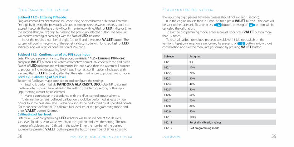
5958 USER MANUALPANDORA DXL 1090L SERVICE-SECURITY SYSTEM
Sublevel 11.2 – Entering PIN-code:Program immobilizer deactivation PIN-code using selected button or buttons. Enter the first digit by pressing the previously selected button (pauses between presses should not exceed 1 second). The base unit will confirm entering with red flash of LED indicator. Enter the second (third, fourth) digit by pressing the previously selected button. The base unit will confirm entering of each digit with red flash of LED indicator.
Input the required number of digits (up to 4) and then press VALET button. The system will confirm receiving of the secret validator code with long red flash of LED indicator and will wait for confirmation of PIN-code.
Sublevel 11.3 - Confirmation of the PIN-code input:Enter PIN-code again similarly to the procedure (LEVEL 11.2 – ENTERING PIN-CODE) and press VALET button. The system will confirm correct PIN-code with red and green flashes of LED indicator and will memorize PIN-code, and then the system will proceed to programming mode awaiting level input. Incorrect confirmation is indicated with long red flash of LED indicator, after that the system will return to programming mode. Level 12 – Calibrating of fuel levelTo control fuel level, make connection and configure the settings:
• Setting is performed via PANDORA ALARMSTUDIO. «Use INP to control fuel level» item should be enabled in the settings, the factory setting of this input (input settings) must be unselected.
• Make a connection in accordance with the «Fuel control input» scheme. To define the current fuel level, calibration should be performed at least by two
points. In some cases fuel level calibration should be performed by all specified points (for more exact definition). To calibrate fuel level, enter the programming mode and press VALET button 12 times.Calibrating of fuel level:Enter level 12 of programming, LED indicator will be lit red. Select the desired sub-level. To adjust zero value, switch on the ignition and save the setting. The total number of sublevels are 12 (listed in the table). Enter the number of the desired sublevel by pressing VALET button (press the button a number of times equals to
P R O G R A M M I N G T H E S Y S T E M
the inputting digit; pauses between presses should not exceed 1 second).Run the engine no less than in 1 minute, then press VALET button – the data will
be sent to the base unit. To save, press button, pressing of button will be canceled the calibration.
To exit the programming mode, enter sublevel 12 or press VALET button more than 12 times.
To reset all calibration values, proceed to sublevel 11 (do not switch on the ignition). Reset confirmation is performed by pressing of button, exit without confirmation and exit the menu are performed by pressing VALET button.
Sublevel Assigning
I-12 0%
I-12.1 10%
I-12.2 20%
I-12.3 30%
I-12.4 40%
I-12.5 50%
I-12.6 60%
I-12.7 70%
I-12.8 80%
I-12.9 90%
I-12.10 100%
I-12.11 Reset all calibration values
I-12.12 Exit programming mode
P R O G R A M M I N G T H E S Y S T E M

6160 USER MANUALPANDORA DXL 1090L SERVICE-SECURITY SYSTEM
Level 15 – Disabling/enabling immobilizer tagTo disabling/enabling of immobilizer tag, enter programming menu and press VALET button 15 times. LED indicator will light green (green light indicates enabled tag) and the system will wait for the «Secret PIN-code» entering. Red light of LED indicates disabled immobilizer tag. Disabling radio tag:
LED indicator will light green after entering the programming level. The system will wait for entering the «Secret PIN-code». Enter the «Secret PIN-code» that is written on the owner’s plastic card. The system will confirm disabling of the radio tag with two sound signals of the siren and a long red LED flash. After that the system will return to the programming menu. If the PIN-code is not entered within 10 seconds or the input is incorrect, a siren will sound one signal, LED will produce the series of red and green flashes and the system will return to the programming menu.Enabling radio tag:
LED indicator will light red after entering the programming level. The system will wait for action. Press VALET button once to enable radio tag. The system will confirm enabling with one short sound signal of a siren and a green LED light. After that the system will return to the programming menu.
Level 16 – Updating built-in Bluetooth modem firmware*Download the firmware from www.pandorainfo.com and install Pandora BT or Pandect BT application on your mobile device.
To update firmware of the built-in Bluetooth modem, enter programming mode and press VALET button 16 times. Find your system in the mobile application, go to detected devices and upload the previously downloaded firmware to the system.
* For Android 4.4 devices or higher that supports Bluetooth 4.0 Low Energy or higher
Level 17 – Programming bypass of original immobilizerBypass learning procedure is performed on this level. A detailed manual can be found in installation scheme for a car in AlarmStudio.
P R O G R A M M I N G T H E S Y S T E M
Enter programming mode and press VALET button 17 times. LED indicator will be lit green. If system installation was performed correctly on successful engine start using a key, LED indicator will flash green. After completing of the procedure, a siren will emit a short sound signal and LED indicator will light green. If the learning procedure finishes with an error, LED indicator will light red and a siren will emit four sound signals.Saving changes:To finish the learning procedure, switch off the ignition and press VALET button. The system will return to programming mode.
Level 18 – Registering and unregistering mobile deviceThe system supports only one mobile device. Registration of a new mobile device (if the system has previously registered device) is not allowed without deleting procedure. When you overwrite the same device in the system memory, you should delete the Bluetooth connection on your mobile device, delete the mobile device from the system memory and then register the mobile device in the system memory.
To register a mobile device, enter the programming mode and press VALET button 18 times. LED indicator will light green (green light indicates the system is ready to register a mobile device) and the system will enter the mobile device registration mode. Red light of LED indicates the system has already had registered mobile device, overwriting of mobile device can be done only after deleting procedure.Mobile device registration:• LED indicator will light green after entering the level. Open the mobile application
and press «Search device» button. The application will search for the system via Bluetooth connection. Select the found system, the system and the mobile device will be automatically paired. The system will confirm the pairing with a sound signal of a siren and red flash of LED indicator.
P R O G R A M M I N G T H E S Y S T E M
WARNING! ! If there is no automatic pairing, enable “PIN request for phone pairing” in the “Radio tag and mobile device functions» settings.
Then perform the registering mobile device procedure again. The PIN will be required to pair the devices (0-0-1-1-1-1)
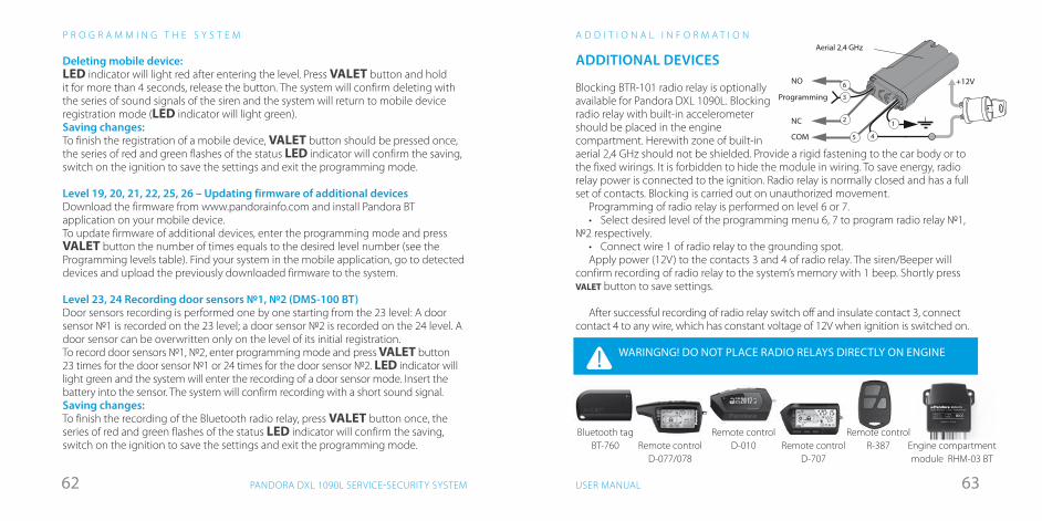
6362 USER MANUALPANDORA DXL 1090L SERVICE-SECURITY SYSTEM
Deleting mobile device:LED indicator will light red after entering the level. Press VALET button and hold it for more than 4 seconds, release the button. The system will confirm deleting with the series of sound signals of the siren and the system will return to mobile device registration mode (LED indicator will light green).Saving changes:To finish the registration of a mobile device, VALET button should be pressed once, the series of red and green flashes of the status LED indicator will confirm the saving, switch on the ignition to save the settings and exit the programming mode.
Level 19, 20, 21, 22, 25, 26 – Updating firmware of additional devicesDownload the firmware from www.pandorainfo.com and install Pandora BT application on your mobile device.To update firmware of additional devices, enter the programming mode and press VALET button the number of times equals to the desired level number (see the Programming levels table). Find your system in the mobile application, go to detected devices and upload the previously downloaded firmware to the system.
Level 23, 24 Recording door sensors №1, №2 (DMS-100 BT)Door sensors recording is performed one by one starting from the 23 level: A door sensor №1 is recorded on the 23 level; a door sensor №2 is recorded on the 24 level. A door sensor can be overwritten only on the level of its initial registration.To record door sensors №1, №2, enter programming mode and press VALET button 23 times for the door sensor №1 or 24 times for the door sensor №2. LED indicator will light green and the system will enter the recording of a door sensor mode. Insert the battery into the sensor. The system will confirm recording with a short sound signal.Saving changes:To finish the recording of the Bluetooth radio relay, press VALET button once, the series of red and green flashes of the status LED indicator will confirm the saving, switch on the ignition to save the settings and exit the programming mode.
ADDITIONAL DEVICES
Blocking BTR-101 radio relay is optionally available for Pandora DXL 1090L. Blocking radio relay with built-in accelerometer should be placed in the engine compartment. Herewith zone of built-in aerial 2,4 GHz should not be shielded. Provide a rigid fastening to the car body or to the fixed wirings. It is forbidden to hide the module in wiring. To save energy, radio relay power is connected to the ignition. Radio relay is normally closed and has a full set of contacts. Blocking is carried out on unauthorized movement.
Programming of radio relay is performed on level 6 or 7.• Select desired level of the programming menu 6, 7 to program radio relay №1,
№2 respectively.• Connect wire 1 of radio relay to the grounding spot.Apply power (12V) to the contacts 3 and 4 of radio relay. The siren/Beeper will
confirm recording of radio relay to the system’s memory with 1 beep. Shortly press VALET button to save settings.
After successful recording of radio relay switch off and insulate contact 3, connect contact 4 to any wire, which has constant voltage of 12V when ignition is switched on.
2
5
1
4
3
NO
NC
COM
Programming
6
Aerial 2,4 GHz
+12V
A D D I T I O N A L I N F O R M A T I O N
WARINGNG! DO NOT PLACE RADIO RELAYS DIRECTLY ON ENGINE
Bluetooth tagBT-760
Remote control D-010Remote control
D-077/078Remote control
D-707
Remote control R-387 Engine compartment
module RHM-03 BT
P R O G R A M M I N G T H E S Y S T E M
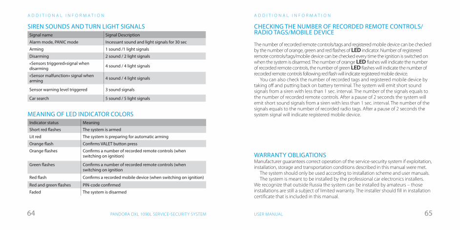
6564 USER MANUALPANDORA DXL 1090L SERVICE-SECURITY SYSTEM
A D D I T I O N A L I N F O R M A T I O N
SIREN SOUNDS AND TURN LIGHT SIGNALSSignal name Signal Description
Alarm mode, PANIC mode Incessant sound and light signals for 30 sec
Arming 1 sound /1 light signals
Disarming 2 sound / 2 light signals
«Sensors triggered»signal when disarming 4 sound / 4 light signals
«Sensor malfunction» signal when arming 4 sound / 4 light signals
Sensor warning level triggered 3 sound signals
Car search 5 sound / 5 light signals
MEANING OF LED INDICATOR COLORSIndicator status Meaning
Short red flashes The system is armed
Lit red The system is preparing for automatic arming
Orange flash Confirms VALET button press
Orange flashes Confirms a number of recorded remote controls (when switching on ignition)
Green flashes Confirms a number of recorded remote controls (when switching on ignition
Red flash Confirms a recorded mobile device (when switching on ignition)
Red and green flashes PIN-code confirmed
Faded The system is disarmed
A D D I T I O N A L I N F O R M A T I O N
CHECKING THE NUMBER OF RECORDED REMOTE CONTROLS/RADIO TAGS/MOBILE DEVICE
The number of recorded remote controls/tags and registered mobile device can be checked by the number of orange, green and red flashes of LED indicator. Number of registered remote controls/tags/mobile device can be checked every time the ignition is switched on when the system is disarmed. The number of orange LED flashes will indicate the number of recorded remote controls, the number of green LED flashes will indicate the number of recorded remote controls following red flash will indicate registered mobile device.
You can also check the number of recorded tags and registered mobile device by taking off and putting back on battery terminal. The system will emit short sound signals from a siren with less than 1 sec. interval. The number of the signals equals to the number of recorded remote controls. After a pause of 2 seconds the system will emit short sound signals from a siren with less than 1 sec. interval. The number of the signals equals to the number of recorded radio tags. After a pause of 2 seconds the system signal will indicate registered mobile device.
WARRANTY OBLIGATIONSManufacturer guarantees correct operation of the service-security system if exploitation, installation, storage and transportation conditions described in this manual were met.
The system should only be used according to installation scheme and user manuals.The system is meant to be installed by the professional car electronics installers.
We recognize that outside Russia the system can be installed by amateurs – those installations are still a subject of limited warranty. The installer should fill in installation certificate that is included in this manual.
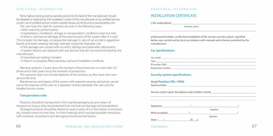
6766 USER MANUALPANDORA DXL 1090L SERVICE-SECURITY SYSTEM
A D D I T I O N A L I N F O R M A T I O N
Parts malfunctioning during warranty period on the fault of the manufacturer should be repaired or replaced by the installation center of the manufacturer or by certified service center. List of certified service centers outside Russia can be found on pandorainfo.com
The user loses the right for warranty services in the following cases:• when warranty period expires;• if exploitation, installation, storage or transportation conditions were not met;• if there is mechanical damage of the external parts of the system after it is sold.
This includes: fire damage, consequential damage in case of car accident, aggressive liquids and water seeping damage, damage caused by improper use;
• if the damage was caused with incorrect settings and parameter adjustment;• if system devices are replaced with any devices that are not recommended by the
manufacturer;• if manufacturer sealing is broken;• if there is no properly filled warranty card and installation certificate.
Warranty period is 3 years since the moment of purchase, but no more than 3,5 (three and a half ) years since the moment of production.
This warranty does not include batteries of the remotes, as they have their own service life time.
Maintenances and repairs of the system with expired warranty period are carried out at the expense of the user on a separate contract between the user and the installer/service center.
Transportation rules
Products should be transported in the original packaging by any means of transport as long as they are protected from mechanical damage and precipitation.
Packaged products should be stored on racks in piles of 6 or less boxes, in enclosed, dry, heated rooms (no less than 1m from heating) which exclude possible interaction with moisture, oil products and damaging environmental factors.
INSTALLATION CERTIFICATE
I, the undersigned ______________________________________________________________ Position, name ______________________________________________________________________________
professional installer, certify that installation of the service-security system, specified below, was carried out by me in accordance with manuals and schemes provided by the manufacturer.
Car specifications:
Car model __________________________________________________________________________________Type _______________________________________________________________________________________ID number (VIN) _____________________________________________________________________________Registration number _________________________________________________________________________
Security system specifications:
Model Pandora DXL 1090L Serial number __________________________________________________________________
Service center name, full address and installer’s stamp _____________________________________________________________________________________________________________________________________________________________________________________________
Signature_____________________/___________________________________/ SignatorWork accepted________________/___________________________________/ SignatorDate «____»___________________20___y.
A D D I T I O N A L I N F O R M A T I O N
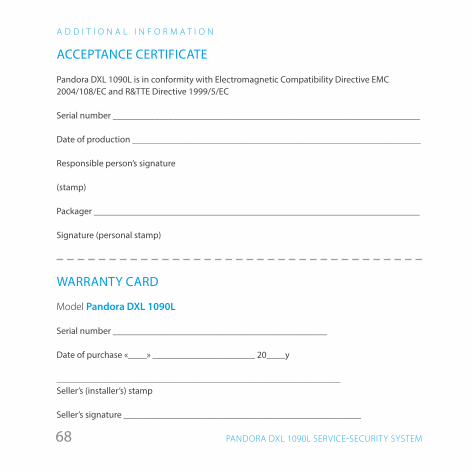
68 PANDORA DXL 1090L SERVICE-SECURITY SYSTEM
A D D I T I O N A L I N F O R M A T I O N
ACCEPTANCE CERTIFICATE
Pandora DXL 1090L is in conformity with Electromagnetic Compatibility Directive EMC 2004/108/EC and R&TTE Directive 1999/5/EC
Serial number __________________________________________________________________
Date of production ______________________________________________________________
Responsible person’s signature
(stamp)
Packager ______________________________________________________________________
Signature (personal stamp)
WARRANTY CARD
Model Pandora DXL 1090L
Serial number ______________________________________________
Date of purchase «____» ______________________ 20____y
_____________________________________________________________ Seller’s (installer’s) stamp
Seller’s signature ___________________________________________________