pam series 2kw model pam40-50 pam80-25 pam160-12 … · operation manual regulated dc power supply...
TRANSCRIPT

OPERATION MANUALRegulated DC Power Supply
PAM series 2kW model
Part No. Z1-002-292, IB002743
Nov. 2005
PAM40-50PAM80-25PAM160-12PAM320-6
PAM series 4kW model
PAM40-100PAM80-50PAM160-25PAM320-12
Use of Operation Manual
Please read through and understand this Operation Manual before operating the product. After reading, alwayskeep the manual nearby so that you may refer to it as needed. When moving the product to another location,be sure to bring the manual as well.
If you find any incorrectly arranged or missing pages in this manual, they will be replaced. If the manual getslost or soiled, a new copy can be provided for a fee. In either case, please contact Kikusui distributor/agent,and provide the “Kikusui Part No.” given on the over.
This manual has been prepared with the utmost care; however, if you have any questions, or note any errors oromissions, please contact Kikusui distributor/agent.
Reproduction and reprinting of this operation manual, whole or partially, without our permission is prohib-ited.
Both unit specifications and manual contents are subject to change without notice.
Copyright© 2001 - 2005 Kikusui Electronics Corporation
Printed in Japan.
PAM Safety Symbols I
For the safe use and safe maintenance of this product, the following sym-bols are used throughout this manual and on the product. Understandthe meanings of the symbols and observe the instructions they indicate(the choice of symbols used depends on the products).
Indicates an imminently hazardous situation which, if ignored,will result in death or serious injury.
Indicates that a high voltage (over 1,000 V) is used here. Touch-ing the part causes a possibly fatal electric shock. If physicalcontact is required by your work, start work only after you makesure that no voltage is output here.
Indicates a potentially hazardous situation which, if ignored,could result in death or serious injury.
Indicates a potentially hazardous situation which, if ignored, mayresult in damage to the product and other property.
Shows that the act indicated is prohibited.
Is placed before the sign “DANGER,” “WARNING,” or “CAU-TION” to emphasize these. When this symbol is marked on theproduct, see the relevant sections in this manual.
Indicates a protective conductor terminal.
Indicates a chassis(frame) terminal.
OR
WARNING
CAUTION
DANGER
Safety Symbols

Safety PrecautionsThe following safety precautions must be observed to avoid fire hazard,electrical shock, accidents, and other failures. Keep them in mind andmake sure that all of them are observed properly.
Users
• This product must be used only by qualified personnel who understand the con-tents of this operation manual.
• If it is handled by disqualified personnel, personal injury may result. Be sure to han-dle it under supervision of qualified personnel (those who have electrical knowl-edge.)
• This product is not designed or manufactured for general home or consumer use.
Purposes of use
• Do not use the product for purposes other than those described in the operationmanual.
Input power
• Use the product with the specified input power voltage.
• For applying power, use the AC power cord provided.
Cover
• There are parts inside the product which may cause physical hazards. Do notremove the external cover.
Installation
• When installing products be sure to observe "Precautions for Installation" describedin this manual.
• To avoid electrical shock, connect the protective ground terminal to electricalground (safety ground).
• When applying power to the products from a switchboard, be sure work is per-formed by a qualified and licensed electrician or is conducted under the direction ofsuch a person.
Operation
Manual
LineVoltage
GNL
II Safety Precautions PAM
Relocation
• Turn off the power switch and then disconnect all cables when relocating theproduct.
• Use two or more persons when relocating the product which weights more than20 kg. The weight of the products can be found on the rear panel of the productand/or in this operation manual.
• Use extra precautions such as using more people when relocating into or out ofpresent locations including inclines or steps.
• Be sure the operation manual be included when the product is relocated.
Operation
• Before starting operations, inspect for abnormalities affecting the input powervoltage. Examine the exterior of the AC power cord. Cut off the power supplybefore performing these inspections.
• If any abnormality or failure is detected in the products, stop using it immediately.Disconnect the AC power cord from the switchboard. Be careful not to allow theproduct to be used before it is completely repaired.
• For output wiring or load cables, use connection cables with larger current capac-ity.
• Do not disassemble or modify the product. If it must be modified, contact Kikusuidistributor/agent.
Maintenance and checking
• To avoid electrical shock, be absolutely sure to stop applying power before per-forming maintenance or checking.
• Do not remove the cover when performing maintenance or checking.
• To maintain performance and safe operation of the product, it is recommendedthat periodic maintenance, checking, cleaning, and calibration be performed.
Service
• Internal service is to be done by Kikusui service engineers. If the product must beadjusted or repaired, contact Kikusui distributor/agent.
Check?
PAM Safety Precautions III

IV Arrangement of this manual PAM
Arrangement of this manual
This Operation Manual is made up of the following sections.
Preface
Provides a brief descriptions of the PAM series and specifies its features.
Chapter1 Setup
Describes the necessary procedure from unpacking to preparation before use.
Chapter2 Precautions and Preparations for Use
This chapter contains essential descriptions that must be understood by the user.This chapter must be read thoroughly before operation is begun.
Chapter3 Basic Operation
This chapter describes the power supply, the protective circuits, and basic frontpanel operations.
Chapter4 Applied Operation
This chapter describes the remote sensing, the analog remote control, and remotemonitoring.
Chapter5 Names and Functions of Controls
Provides an outline of the switches and terminals on the panels, including theirnames and functions.
Read this chapter to learn the meanings of the alert marksindicated on the panels of the unit.
Chapter6 Maintenance
This chapter describes unit maintenance and calibration, as well as the proper pro-cedures for handling unit malfunctions.
Chapter7 Specifications
This chapter provides the electrical and mechanical specifications for the PAMseries, as well as a list of accessories.
Appendix
Explains how to check the ROM version.

Contents
Safety Symbols - - - - - - - - - - - - - - - - - - - - - - - - - - - - - - - - - - - - - - - - - - - - - - I
Safety Precautions- - - - - - - - - - - - - - - - - - - - - - - - - - - - - - - - - - - - - - - - - - - II
Preface - - - - - - - - - - - - - - - - - - - - - - - - - - - - - - - - - - - - - - - - - - - - - - - - - - P-1
Chapter 1 Setup
1.1 Checking at unpacking - - - - - - - - - - - - - - - - - - - - - - - - - - - - - - - - - - - - - - - - - -1-2
1.2 Precautions for installation - - - - - - - - - - - - - - - - - - - - - - - - - - - - - - - - - - - - - - -1-6
1.3 Precautions for moving - - - - - - - - - - - - - - - - - - - - - - - - - - - - - - - - - - - - - - - - - -1-7
1.4 Input power- - - - - - - - - - - - - - - - - - - - - - - - - - - - - - - - - - - - - - - - - - - - - - - - - -1-8
1.5 Connecting the AC power cord - - - - - - - - - - - - - - - - - - - - - - - - - - - - - - - - - - - -1-9
1.6 Grounding - - - - - - - - - - - - - - - - - - - - - - - - - - - - - - - - - - - - - - - - - - - - - - - - - 1-10
Chapter 2 Precautions and Preparations for Use
2.1 Inrush current - - - - - - - - - - - - - - - - - - - - - - - - - - - - - - - - - - - - - - - - - - - - - - - -2-2
2.2 Negative voltage and current - - - - - - - - - - - - - - - - - - - - - - - - - - - - - - - - - - - - - -2-2
2.3 Load - - - - - - - - - - - - - - - - - - - - - - - - - - - - - - - - - - - - - - - - - - - - - - - - - - - - - -2-3
2.3.1 When load current has peaks or is pulse-shaped - - - - - - - - - - - - - - - - - - - -2-3
2.3.2 When a load generates a reverse current to the power supply- - - - - - - - - - - -2-4
2.3.3 In case of load with accumulated energy, such as batteries - - - - - - - - - - - - -2-5
2.4 Constant-voltage and constant-current power supplies - - - - - - - - - - - - - - - - - - - - -2-6
2.5 Alarm- - - - - - - - - - - - - - - - - - - - - - - - - - - - - - - - - - - - - - - - - - - - - - - - - - - - - -2-8
2.6 Grounding the output terminal - - - - - - - - - - - - - - - - - - - - - - - - - - - - - - - - - - - - 2-10
Chapter 3 Basic Operation
3.1 Turning on the power - - - - - - - - - - - - - - - - - - - - - - - - - - - - - - - - - - - - - - - - - - -3-2
3.2 Basic operations - - - - - - - - - - - - - - - - - - - - - - - - - - - - - - - - - - - - - - - - - - - - - -3-4
3.2.1 Setting the output - - - - - - - - - - - - - - - - - - - - - - - - - - - - - - - - - - - - - - - - -3-4
3.2.2 OVP (OverVoltage Protection) trip point presetting - - - - - - - - - - - - - - - - - -3-8
3.2.3 Using as a constant voltage power supply- - - - - - - - - - - - - - - - - - - - - - - - 3-12
3.2.4 Using as a constant current power supply - - - - - - - - - - - - - - - - - - - - - - - - 3-13
3.3 Connecting load- - - - - - - - - - - - - - - - - - - - - - - - - - - - - - - - - - - - - - - - - - - - - - 3-14
3.3.1 load cables - - - - - - - - - - - - - - - - - - - - - - - - - - - - - - - - - - - - - - - - - - - - 3-14
3.3.2 Connecting to the output terminal - - - - - - - - - - - - - - - - - - - - - - - - - - - - - 3-16
3.4 Memory function - - - - - - - - - - - - - - - - - - - - - - - - - - - - - - - - - - - - - - - - - - - - - 3-21
3.5 LOCK function - - - - - - - - - - - - - - - - - - - - - - - - - - - - - - - - - - - - - - - - - - - - - - 3-22
PAM Contents V

Chapter 4 Applied Operation
4.1 General description - - - - - - - - - - - - - - - - - - - - - - - - - - - - - - - - - - - - - - - - - - - - 4-2
4.1.1 J1 and J2 terminal boards - - - - - - - - - - - - - - - - - - - - - - - - - - - - - - - - - - - 4-3
4.1.2 S1 switches - - - - - - - - - - - - - - - - - - - - - - - - - - - - - - - - - - - - - - - - - - - - 4-6
4.2 Remote sensing - - - - - - - - - - - - - - - - - - - - - - - - - - - - - - - - - - - - - - - - - - - - - - 4-7
4.3 Analog remote control - - - - - - - - - - - - - - - - - - - - - - - - - - - - - - - - - - - - - - - - - 4-10
4.3.1 Output control with analog signal - - - - - - - - - - - - - - - - - - - - - - - - - - - - 4-10
4.3.2 Output ON/OFF control with an external contact - - - - - - - - - - - - - - - - - - 4-29
4.4 Remote monitoring - - - - - - - - - - - - - - - - - - - - - - - - - - - - - - - - - - - - - - - - - - - 4-32
4.4.1 External monitor for operating mode - - - - - - - - - - - - - - - - - - - - - - - - - - 4-32
4.4.2 External monitor for output voltage and output current - - - - - - - - - - - - - - 4-33
Chapter 5 Names and Functions of Controls
5.1 Front panel - - - - - - - - - - - - - - - - - - - - - - - - - - - - - - - - - - - - - - - - - - - - - - - - - 5-2
5.2 Rear panel - - - - - - - - - - - - - - - - - - - - - - - - - - - - - - - - - - - - - - - - - - - - - - - - - - 5-7
Chapter 6 Maintenance
6.1 Cleaning - - - - - - - - - - - - - - - - - - - - - - - - - - - - - - - - - - - - - - - - - - - - - - - - - - - 6-2
6.1.1 Cleaning the panel- - - - - - - - - - - - - - - - - - - - - - - - - - - - - - - - - - - - - - - - 6-2
6.1.2 Cleaning the dust filter - - - - - - - - - - - - - - - - - - - - - - - - - - - - - - - - - - - - - 6-2
6.2 Inspection - - - - - - - - - - - - - - - - - - - - - - - - - - - - - - - - - - - - - - - - - - - - - - - - - - 6-4
6.3 Calibration- - - - - - - - - - - - - - - - - - - - - - - - - - - - - - - - - - - - - - - - - - - - - - - - - - 6-4
6.4 Malfunctions and Causes - - - - - - - - - - - - - - - - - - - - - - - - - - - - - - - - - - - - - - - - 6-5
Chapter 7 Specifications
Appendix - - - - - - - - - - - - - - - - - - - - - - - - - - - - - - - - - - - - - - - - - - - - - - - - - A-1
Index- - - - - - - - - - - - - - - - - - - - - - - - - - - - - - - - - - - - - - - - - - - - - - - - - - - - -I-1
VI Contents PAM
Preface
About this manual
This Operation Manual describes the PAM series, including the specific typesnamed below.
PAM series 2kW model• PAM40-50
• PAM80-25
• PAM160-12
• PAM320-6
PAM series 4kW model• PAM40-100
• PAM80-50
• PAM160-25
• PAM320-12
Outline of the PAM series
Models in the PAM series are regulated DC power supplies that automatically shiftbetween constant voltage and constant current, based on a switching regulatingmethod.
Feature
• The switching regulating method used in the series realizes high efficiency min-imal heat generation, and lightweight.
• The external voltage or resistor enables you to remotely control output voltagesand currents.
• When used together with models in the Kikusui’s power supply controllerPIA4800 series, which have GPIB and RS-232C interfaces, the PAM series per-mits systematization of various devices, such as automatic testers.
• 4kW model permits you to run up to three same rating models in parallel byusing the parallel operation option (factory option).
PAM Preface P-1

P-2 Preface PAM

11
Chapter 1 SetupDescribes the necessary procedure from unpacking to preparation before use.
PAM Setup 1-1

1.1 Checking at unpacking
When you unpack the product, make sure that you have all the parts and that nonehave been damaged during transportation.
For models with factory-installed optional equipment, check to verify that all neces-sary optional equipment is included and that any required accessories are includedwith the optional equipment.
Table 1-1 shows the common accessories for each PAM series model.
For details concerning models featuring GPIB/TP-BUS interface options, see Fig.1-4 through Fig. 1-6. For models featuring optional parallel operation, see also Fig.1-7 and Fig. 1-8.
If any part is damaged or missing, contact Kikusui distributor/agent.
• We recommend that all packing materials be saved, in case the product needs to betransported at a later date.
Fig.1-1 The common accessories for each PAM series model
NOTE
Operation Manual (1 copy)Power cords (3 pcs., 14mm2, 3m)(Insulation sleeve color: green, white, black 1 pc. each)
Chassis connecting cable (1 pc.) Clamper (1 pair)
Fastening screws (4 pcs.)[M3-002-181]
Push nuts (4 pcs.)[M8-500-003]
Fastening screw (1 pc.)[M3-001-111]
[Z1-002-292][91-87-6151]
[P2-000-206]
[P2-000-082]
[CN]
Weight sticker (1 pc.)
[A8-000-003]
This sticker is included with the PAM series 4 kW model. Attach it to a visible part of the product.
1-2 Setup PAM
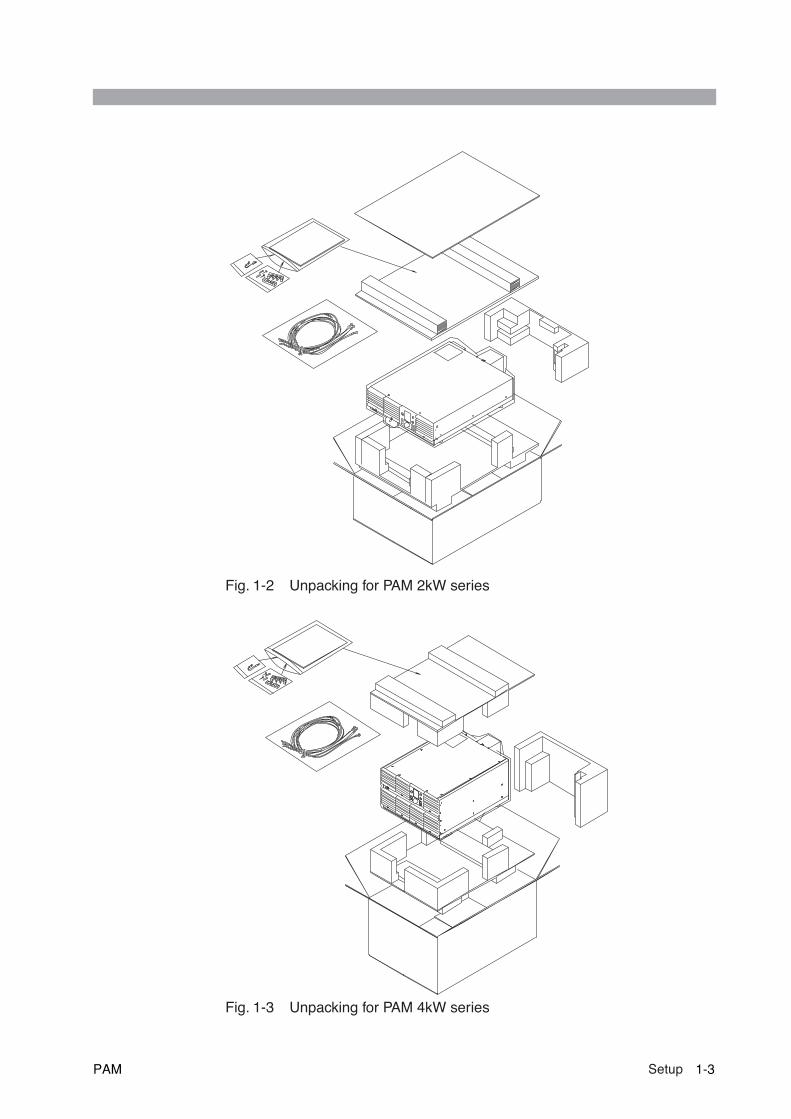
Fig. 1-2 Unpacking for PAM 2kW series
Fig. 1-3 Unpacking for PAM 4kW series
PAM Setup 1-3

Checking at unpacking(cont’d)
Checking models with the GPIB/TP-BUS interface options
Fig. 1-4 Location at which the GPIB/TP-BUS interface option is installed
Fig. 1-5 Accessory for the GPIB interface option
Fig. 1-6 Accessories for the TP-BUS interface option
• The Operation Manual is common to both the GPIB and TP-BUS interfaceoptions.
SET ERR
S2
SLAVE
J4NEXT IN
MASTER
J5NEXTOUT
J3TOTALCUR MON
NL
6
1
1
2
12
7
1
8
J1
J2
S1
OFFON
DCOUTPUT
AC INPUT90--132V / 180--250V50 / 60Hz 5.5kW MAX
0--40V 0--100A
NL
6
1
1
2
12
7
1
8
J1
J2
S1
INPUT SELECT
200V 100VOFF
OFF
ON
ON
DCOUTPUT
AC INPUT90--132V / 180--250V
50--60Hz 52.8 /28.6A MAX
0--40V 0--50A
GPIB interface option
TP-BUS interface option
GPIB
24816
1
PILOT
OFFON
AD
DR
ESS
TP --BUS
TERMN
SERVICE
NODE ADRS
PILOT
OFFON
OFF
ON
124816 A
DD
RES
S
PAM series 4kW model
PAM series 2kW model
Interface option operation manual (1 copy)
[Z1-002-392]
Interface option operation manual (1copy)TP-BUS connector (1 pc.) Core for TP-BUS (1 pc.)
[84-61-5102] [67-90-0080] [Z1-002-392]
NOTE
1-4 Setup PAM

Checking models with the optional parallel operation (4kW model only)
Fig. 1-7 Location at which the optional parallel operation installed
Fig. 1-8 Accessories for the optional parallel operation
SET ERR
S2
SLAVE
J4NEXT IN
MASTER
J5NEXTOUT
J3TOTALCUR MON
NL
6
1
1
2
12
7
1
8
J1
J2
S1
OFFON
DCOUTPUT
AC INPUT90--132V / 180--250V50 / 60Hz 5.5kW MAX
0--40V 0--100A
Optional parallel operation
PAM series 4kW model
SET ERR
S2
SLAVE
J4NEXT IN
MASTER
J5NEXTOUT
J3TOTALCUR MON
Optional Parallel Operation Manual(1copy)Signal connection cable for parallel operation(1pc., 1.3m)
[Z1-002-382][83-22-6290]
PAM Setup 1-5

1.2 Precautions for installation
Be sure to observe the following precautions when installing the power supply.
■ Do not use the power supply in a flammable atmosphere.
To prevent explosion or fire, do not use the power supply near alcohol, thinner, orother combustible materials, or in an atmosphere containing such vapors.
■ Avoid locations where the power supply is exposed to high temperatures or direct sunlight.
Do not locate the power supply near a heater or in areas subject to drastic tempera-ture changes.
Operating temperature range: 0°C to 50°C
Storage temperature range: -10°C to +60°C
■ Avoid humid environments.
Do not locate the power supply in a high-humidity environment—near a boiler,humidifier, or water supply.
Operating humidity range: 20% to 80% RH
(no dew condensation is allowed)
Storage humidity range: 90% RH or less
(no dew condensation is allowed)
Condensation may occur even within the operating humidity range. In that case, donot start using the power supply until the location is completely dry.
■ Do not place the power supply in a corrosive atmosphere.
Do not install the power supply in a corrosive atmosphere or one containing sulfuricacid mist or the like. This may cause corrosion of various conductors and imperfectcontact with connectors, leading to malfunction and failure, or in the worst case, afire.
■ Do not locate the power supply in a dusty environment.
Dirt and dust in the power supply may cause electrical shock or fire.
■ Do not use the power supply where ventilation is poor.
The power supply employs a forced air cooling system. Air is taken in from intakeports located on the power supply's sides and front, and is exhausted from the rear.Prepare sufficient space around the power supply so that the intake ports andexhaust port are always completely unobstructed. Otherwise, heat may accumulatein the power supply, resulting in fire.
■ Do not place any object on the power supply.
Particularly a heavy one, as doing so could result in a malfunction.
1-6 Setup PAM

■ Do not place the power supply on a tilted surface or in a location subject to vibrations.
If placed on a non-level surface or in a location subject to vibration, the power sup-ply may fall, resulting in damage and injury.
■ Do not use the power supply in locations affected by strong magnetic or electric fields.
Operation in a location subject to magnetic or electric fields may cause the powersupply to malfunction, resulting in electrical shock or fire.
■ Do not use the power supply in locations where highly-sensitive measuring instruments or receivers are nearby.
Such instruments may be affected by the noise generated by the power supply.
1.3 Precautions for moving
When moving or transporting the power supply to an installation site, observe thefollowing precautions.
■ Turn the POWER switch off.
Moving the power supply with the power on may result in electrical shock or dam-age.
■ Turn off the switch on the switchboard, and remove all wirings connected.
Moving the power supply with cables connected may break the cables or cause thepower supply to fall, resulting in injury.
■ For transportation, use the special packing material for the power supply.
Transport the power supply in its original package to prevent vibration and falls,which may damage the power supply. If you require packing material, contactKikusui distributor/agent.
PAM Setup 1-7
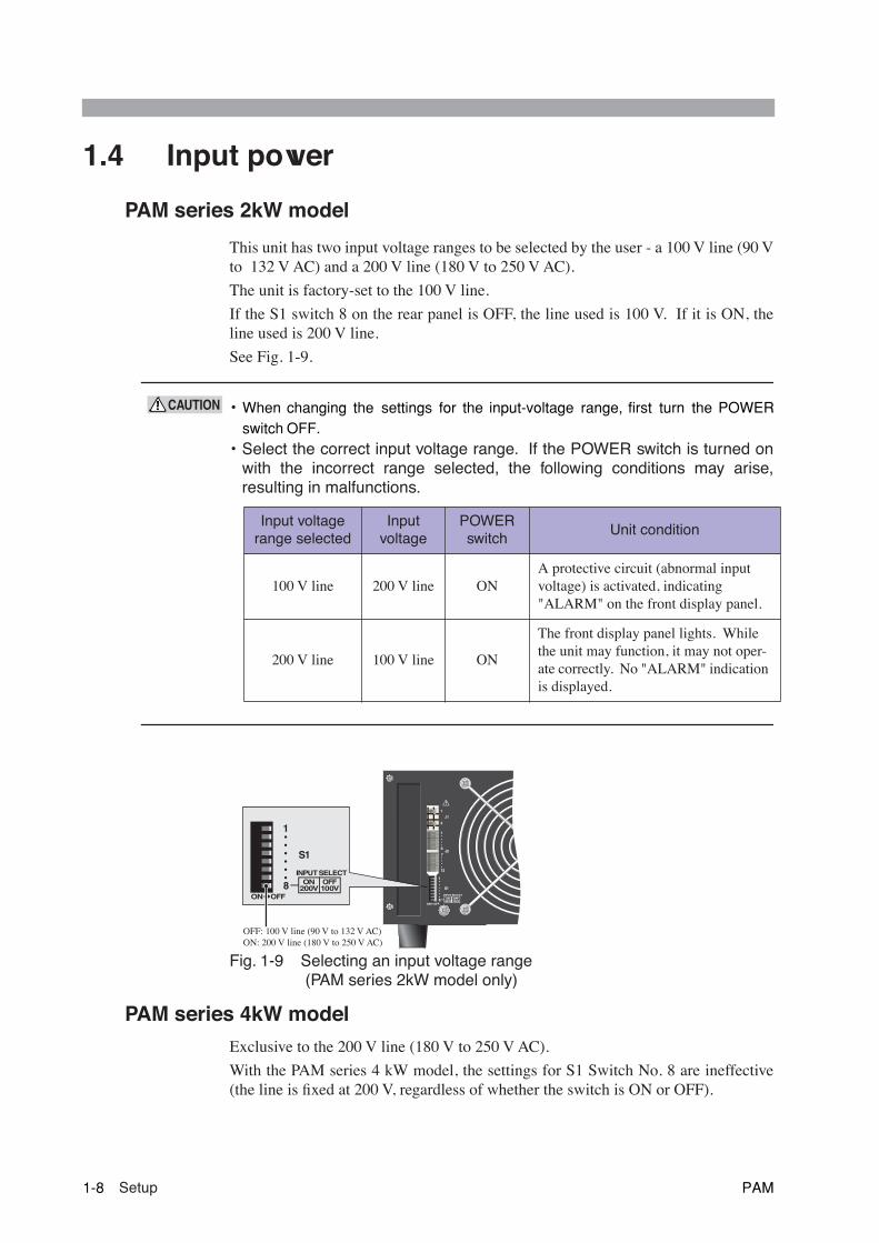
1.4 Input power
PAM series 2kW model
This unit has two input voltage ranges to be selected by the user - a 100 V line (90 Vto 132 V AC) and a 200 V line (180 V to 250 V AC).
The unit is factory-set to the 100 V line.
If the S1 switch 8 on the rear panel is OFF, the line used is 100 V. If it is ON, theline used is 200 V line.
See Fig. 1-9.
• When changing the settings for the input-voltage range, first turn the POWERswitch OFF.
• Select the correct input voltage range. If the POWER switch is turned onwith the incorrect range selected, the following conditions may arise,resulting in malfunctions.
Fig. 1-9 Selecting an input voltage range (PAM series 2kW model only)
PAM series 4kW model
Exclusive to the 200 V line (180 V to 250 V AC).
With the PAM series 4 kW model, the settings for S1 Switch No. 8 are ineffective(the line is fixed at 200 V, regardless of whether the switch is ON or OFF).
Input voltage range selected
Input voltage
POWER switch
Unit condition
100 V line 200 V line ONA protective circuit (abnormal input voltage) is activated, indicating "ALARM" on the front display panel.
200 V line 100 V line ON
The front display panel lights. While the unit may function, it may not oper-ate correctly. No "ALARM" indication is displayed.
CAUTION
6
1
1
2
12
7
1
8
J1
J2
S1
INPUT SELECT
200V 100VOFF
OFF
ON
ON
1
8
S1
INPUT SELECT
200V 100VOFF
OFF
ON
ON
OFF: 100 V line (90 V to 132 V AC)ON: 200 V line (180 V to 250 V AC)
1-8 Setup PAM
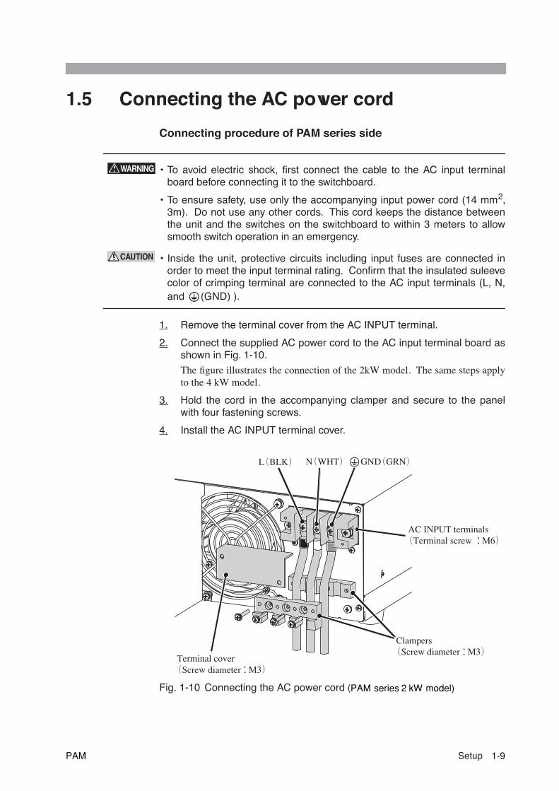
1.5 Connecting the AC power cord
Connecting procedure of PAM series side
• To avoid electric shock, first connect the cable to the AC input terminalboard before connecting it to the switchboard.
• To ensure safety, use only the accompanying input power cord (14 mm2,3m). Do not use any other cords. This cord keeps the distance betweenthe unit and the switches on the switchboard to within 3 meters to allowsmooth switch operation in an emergency.
• Inside the unit, protective circuits including input fuses are connected inorder to meet the input terminal rating. Confirm that the insulated suleevecolor of crimping terminal are connected to the AC input terminals (L, N,and (GND) ).
1. Remove the terminal cover from the AC INPUT terminal.
2. Connect the supplied AC power cord to the AC input terminal board asshown in Fig. 1-10.
The figure illustrates the connection of the 2kW model. The same steps applyto the 4 kW model.
3. Hold the cord in the accompanying clamper and secure to the panelwith four fastening screws.
4. Install the AC INPUT terminal cover.
Fig. 1-10 Connecting the AC power cord (PAM series 2 kW model)
WARNING
CAUTION
L(BLK) N(WHT) GND(GRN)
AC INPUT terminals(Terminal screw :M6)
Clampers(Screw diameter:M3)
Terminal cover(Screw diameter:M3)
PAM Setup 1-9

Connecting the AC power cord(Cont’d)
Connecting procedure of switchboard side
1. Attach crimp terminals to the wires of the AC power cord of switchboardside.
• Check the terminal screw on the switchboard, and crimp a terminal oneach wire end suitable for the said terminal screw. (This connection mustbe performed by qualified personnel.)
2. Turn off the switch on the switchboard.
3. Connect the AC power cord to the switchboard.
Confirm that the specified polarity of AC input terminals are connected to theswitchboard.
1.6 Grounding
• Not grounding the power supply creates danger of electric shock.
• Connect the ground terminal to an electrical ground (safety ground)
• Not performing adequate grounding work on the power supply results inmalfunction or the production of large noises from the power supply
Securely connect the GND line (identified by the green insulation sleeve on theclamp terminal of the AC INPUT terminal) on the input power cord to the groundterminal on the switchboard.
CAUTION
WARNING
CAUTION
1-10 Setup PAM
22
Chapter 2 Precautions andPreparations for Use
This chapter contains essential descriptions that must be understood by the user.This chapter must be read thoroughly before operation is begun.
PAM Precautions and Preparations for Use 2-1
2.1 Inrush current
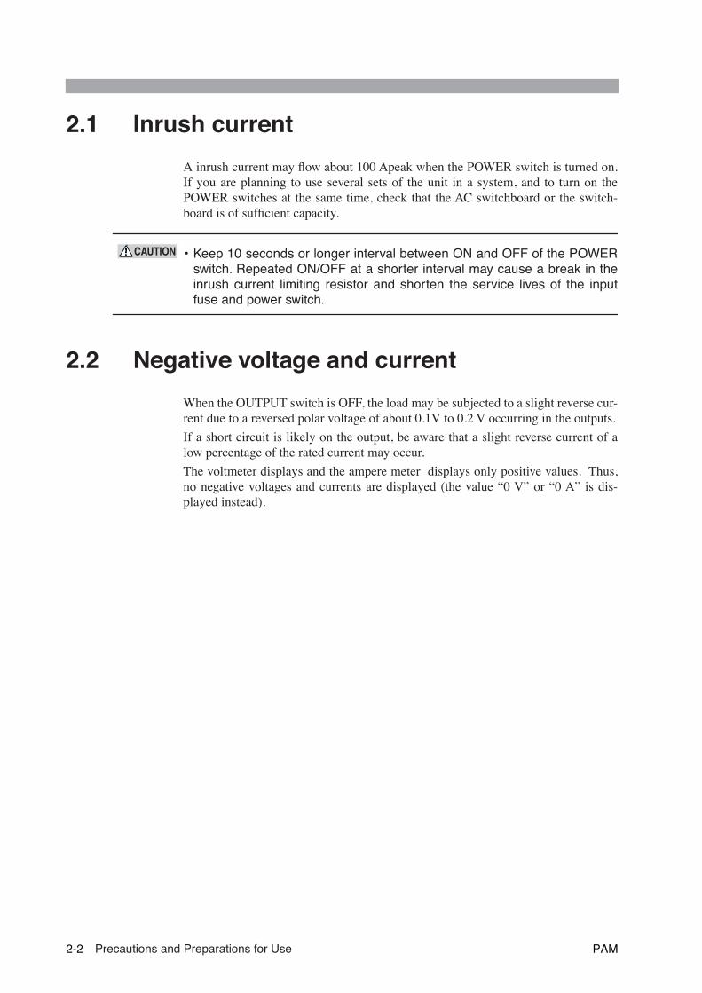
A inrush current may flow about 100 Apeak when the POWER switch is turned on.If you are planning to use several sets of the unit in a system, and to turn on thePOWER switches at the same time, check that the AC switchboard or the switch-board is of sufficient capacity.
• Keep 10 seconds or longer interval between ON and OFF of the POWERswitch. Repeated ON/OFF at a shorter interval may cause a break in theinrush current limiting resistor and shorten the service lives of the inputfuse and power switch.
2.2 Negative voltage and current
When the OUTPUT switch is OFF, the load may be subjected to a slight reverse cur-rent due to a reversed polar voltage of about 0.1V to 0.2 V occurring in the outputs.
If a short circuit is likely on the output, be aware that a slight reverse current of alow percentage of the rated current may occur.
The voltmeter displays and the ampere meter displays only positive values. Thus,no negative voltages and currents are displayed (the value “0 V” or “0 A” is dis-played instead).
CAUTION
2-2 Precautions and Preparations for Use PAM
2.3 Load
Note that the output may become unstable when one of the following loads is con-nected.
2.3.1 When load current has peaks or is pulse-shaped
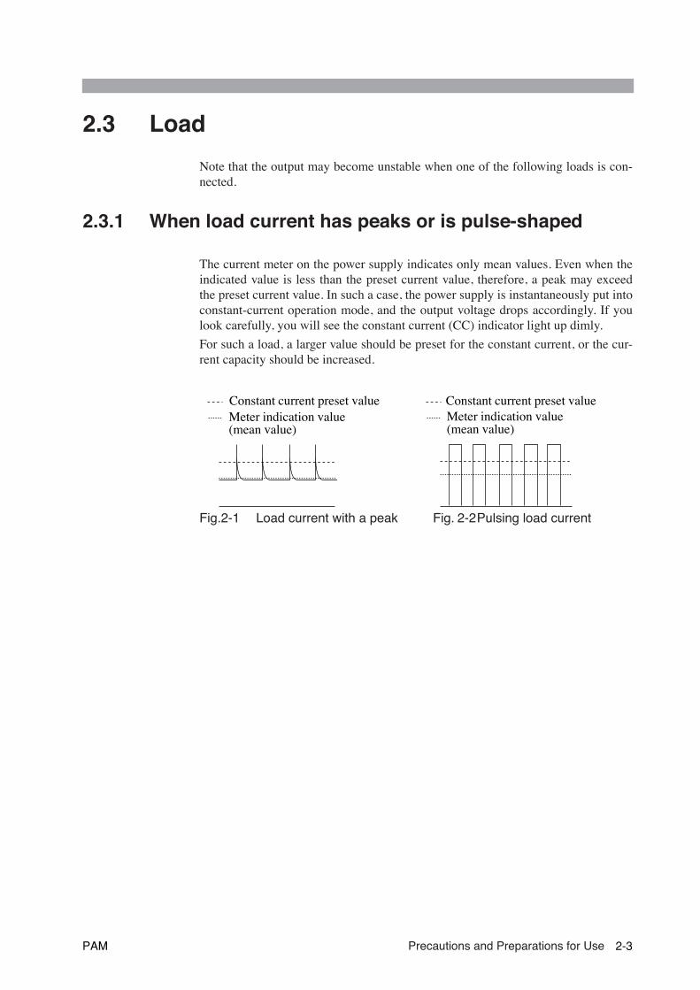
The current meter on the power supply indicates only mean values. Even when theindicated value is less than the preset current value, therefore, a peak may exceedthe preset current value. In such a case, the power supply is instantaneously put intoconstant-current operation mode, and the output voltage drops accordingly. If youlook carefully, you will see the constant current (CC) indicator light up dimly.
For such a load, a larger value should be preset for the constant current, or the cur-rent capacity should be increased.
Fig.2-1 Load current with a peak Fig. 2-2Pulsing load current
Constant current preset valueMeter indication value �(mean value)
Constant current preset value��Meter indication value �(mean value)
PAM Precautions and Preparations for Use 2-3
2.3.2 When a load generates a reverse current to the powersupply
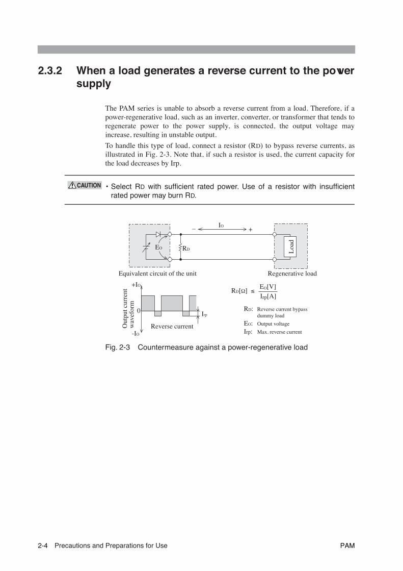
The PAM series is unable to absorb a reverse current from a load. Therefore, if apower-regenerative load, such as an inverter, converter, or transformer that tends toregenerate power to the power supply, is connected, the output voltage mayincrease, resulting in unstable output.
To handle this type of load, connect a resistor (RD) to bypass reverse currents, asillustrated in Fig. 2-3. Note that, if such a resistor is used, the current capacity forthe load decreases by Irp.
• Select RD with sufficient rated power. Use of a resistor with insufficientrated power may burn RD.
Fig. 2-3 Countermeasure against a power-regenerative load
CAUTION
IO
RDEO
– +
0
-IO
+IO
Irp
RD[Ω] ≤ EO[V]
Irp[A]
RD: Reverse current bypass dummy load
EO: Output voltage
Irp: Max. reverse current
Equivalent circuit of the unit Regenerative load
Loa
d
Out
put c
urre
ntw
avef
orm
Reverse current
2-4 Precautions and Preparations for Use PAM
2.3.3 In case of load with accumulated energy, such as bat-teries
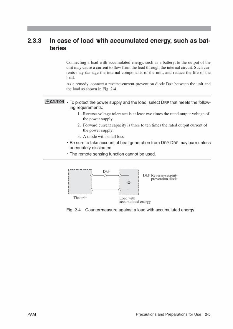
Connecting a load with accumulated energy, such as a battery, to the output of theunit may cause a current to flow from the load through the internal circuit. Such cur-rents may damage the internal components of the unit, and reduce the life of theload.
As a remedy, connect a reverse-current-prevention diode DRP between the unit andthe load as shown in Fig. 2-4.
• To protect the power supply and the load, select DRP that meets the follow-ing requirements:
1. Reverse-voltage tolerance is at least two times the rated output voltage of the power supply.
2. Forward current capacity is three to ten times the rated output current of the power supply.
3. A diode with small loss
• Be sure to take account of heat generation from DRP. DRP may burn unlessadequately dissipated.
• The remote sensing function cannot be used.
Fig. 2-4 Countermeasure against a load with accumulated energy
CAUTION
DRP
The unit Load with accumulated energy
DRP: Reverse-current- prevention diode
PAM Precautions and Preparations for Use 2-5
2.4 Constant-voltage and constant-current power supplies
The PAM series is capable of both constant voltage and constant current operation.The following describes these operation.
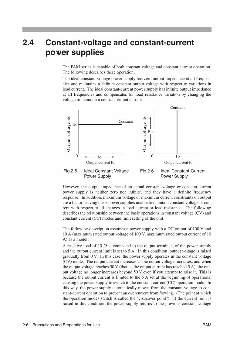
The ideal constant-voltage power supply has zero output impedance at all frequen-cies and maintains a definite constant output voltage with respect to variations inload current. The ideal constant-current power supply has infinite output impedanceat all frequencies and compensates for load resistance variation by changing thevoltage to maintain a constant output current.
However, the output impedance of an actual constant-voltage or constant-currentpower supply is neither zero nor infinite, and they have a definite frequencyresponse. In addition, maximum voltage or maximum current constraints on outputare a factor, leaving these power supplies unable to maintain constant voltage or cur-rent with respect to all changes in load current or load resistance. The followingdescribes the relationship between the basic operations in constant voltage (CV) andconstant current (CC) modes and limit setting of the unit.
The following description assumes a power supply with a DC output of 100 V and10 A (maximum rated output voltage of 100 V, maximum rated output current of 10A) as a model.
A resistive load of 10 Ω is connected to the output terminals of the power supplyand the output current limit is set to 5 A. In this condition, output voltage is raisedgradually from 0 V. In this case, the power supply operates in the constant voltage(CV) mode. The output current increases as the output voltage increases, and whenthe output voltage reaches 50 V (that is, the output current has reached 5 A), the out-put voltage no longer increases beyond 50 V even if you attempt to raise it. This isbecause the output current is limited to the 5 A set at the beginning of operations,causing the power supply to switch to the constant current (CC) operation mode. Inthis way, the power supply automatically moves from the constant-voltage to con-stant-current operation to prevent an overcurrent from flowing. (The point at whichthe operation modes switch is called the "crossover point"). If the current limit israised in this condition, the power supply returns to the previous constant voltage
Fig. 2-5 Ideal Constant-Voltage Power Supply
Fig. 2-6 Ideal Constant-Current Power Supply
Output current Io Output current Io
0 0
Constant
Constant
Output voltage Eo
Output voltage Eo
Eo
Io Io
Eo
2-6 Precautions and Preparations for Use PAM

operation, allowing you to increase the output voltage further. If the current limit isincreased from 5 A to 9 A in Fig. 2-7, a voltage of up to 90 V can be output.
Next, let's assume a case in which a load resistance of 4 Ω is used. The output cur-rent limit is regarded as the rated maximum output current. When you increase theoutput voltage from 0 V, the output current reaches the power supply's maximumcurrent rating when the output voltage reaches 40 V; the power supply cannot outputa voltage above 40 V with the maximum current flowing. This is its limit, eventhough the power supply is not yet generating half its output capacity in terms ofpower. If you wish to increase the output voltage further, the initial unit needs to bereplaced by a model having larger current capacity. Particularly for loads intowhich a transient peak current flows, the current must be set such that its peak doesnot reach (or exceed) the current limit. If the unit enters constant-current operationmode even when the current is set within the rated output current, the current capac-ity needs to be raised.
Next, we consider a case of using a load resistance of 25 Ω. In this case, when theoutput current limit is set to 4 A or more, the power supply is capable of outputtingvoltages from 0 V to the rated maximum output voltage while in constant-voltageoperation mode. In this load condition, the output voltage limit is the rated maxi-mum output voltage (for these conditions) and the output current is graduallyincreased from 0 A. At this time, the power supply is operating in the constant-cur-rent (CC) operation mode. The power supply increases the output voltage in orderto source the current setting. When the output voltage reaches the supply's maxi-mum rated output of 100 V, no more current can be sourced to this load, regardlessof the current setting. To continue applying a current under these conditions, youmust use a model compatible with higher voltage outputs. Particularly for loadswhere a transient surge voltage is generated, the voltage must be set so that the surgevoltage does not reach (or exceed) the voltage limit.
Fig. 2-7 Constant Voltage Operation and Constant Current Operation
Load line of RL = 4 Ω�
Load line of RL = 10 Ω�Load line of RL = 25 Ω�
Area where current�capacity needs to be increased
Area where voltage �increase is required
0 5 A 10 A9 A4 A
50 V
90 V
100 V
40 V
Output current Io
Out
put v
olta
ge E
o
PAM Precautions and Preparations for Use 2-7

2.5 AlarmThe PAM series has the following protective circuits. Once a protective circuit isactivated, the output is cut off, and an ALARM LED on the front panel lights up.The alarm(ALM) signal is output to terminal 4 of the J2 terminal board. See Fig. 2-8 and Fig. 2-9.
Whenever a protective function is activated, identify and remove the cause. Then,on the control panel, press the ALARM RESET switch or reclose the POWERswitch to turn OFF the alarm. Where there is an input-voltage abnormality, how-ever, simply reclose the POWER switch. When the POWER switch is reclosed andthe OUTPUT switch is ON, the output will be ON as the alarm is released. Until thecause of the alarm is removed, the protective function will reactivate, turning theoutput OFF.
For details concerning the procedure to be followed when the ALARM LED lights,see "6.4 Malfunctions and Causes"
Protective circuits
• OVP (Overvoltage protection)Activates when the output exceeds the voltage preset as an overvoltage (OVPtrip point).
Preset range: 20 % to 110 % of the rated output voltage.
When the OVP circuit generates an alarm, “OVP” appears on the voltmeterdisplay. If the output voltage exceeds the OVP trip point as the dial on theoperation block is being turned, the preset output voltage may appear on thevoltmeter (the SET switch on the operation block lights).
• OHP (Overheat protection)Activates when the temperature of the unit’s internal heat sink rises to abnor-mal levels under certain conditions, including the following:
The unit is used in an environment above its operating ambient tempera-ture.
The inlet or outlet is choked.
The fan motor is stopped by a foreign object.
When the OHP circuit issues an alarm, “OHP” appears on the voltmeter dis-play. Once the internal temperature returns to a normal level, the “OHP ” message isno longer displayed. However, the ALARM LED remains lit until the alarm is turnedOFF.
• Abnormal input voltage
In PAM series 2kW model, activates when a voltage on the 200 V line is inputby mistake to the AC IN terminal while the 100 V range is selected.
For the input voltage range, see "1.4 Input power"
• Abnormal sensing
Activates when there is an abnormal sensing voltage. One of the causes is areversed polarity connection of the sensing cable.
• Internal unit abnormality
Activates in the event of a failure or abnormal action involving an internal unit.
2-8 Precautions and Preparations for Use PAM

Fig. 2-8 ALARM indication (OHP)
Fig. 2-9 ALARM output
• Mishandling of J2 terminal board may lead to electric shock. Before wiringto the alarm signal terminal, see "4.1.1 J1 and J2 terminal boards"
The alarm output signal is insulated from other terminals with an open collector-type photocoupler.
All other status outputs (CV MODE of terminal 2 and CC MODE of terminal 3) arealso insulated from each other. However, note that the COM line (STAT COM ofterminal 1) is used for all status outputs and the alarm output signal. For more infor-mation, see "4.4.1 External monitor for operating mode".
CC
CV
ALARM
V
A
OFFOUTPUTO N
In the case of an OVP or OHP alarm, the ALARM LED lights, and the voltmeter displays "OVP" (*1) or "OHP". In the case of other alarms, only the ALARM LED lights.
ALARM LED
*1: See the "OVP" section on the preceding page.
J2
11
6
4
WARNING
PAM Precautions and Preparations for Use 2-9

2.6 Grounding the output terminal
The output terminals of this unit are insulated from protective conductor terminal.When the GND line of the input power cord is connected to the ground terminal onthe switchboard, the unit's chassis assumes a grounding potential, as shown in Fig.2-10. Cables and loads connected to the output terminals (including the sensing ter-minal J1) must be insulated from the chassis with at least the isolation voltage of theunit (*1, also see Table 2-1). Terminals 5 through 12 on the J2 terminal board onthe rear panel (analog remote control and output monitor terminal) will have nearlyequal potential on the circuit as the - (neg.) output terminal of the unit. Accordingly,cables and devices connected to these terminals must be insulated with at least theisolation voltage of the unit.
Fig. 2-10 Without grounding the output terminal
Table2-1 Isolation voltage value
*1Isolation voltage: The maximum external voltage that may be applied betweenan output terminal on the power supply and protective con-ductor terminal (chassis).
PAM series 2 kW model PAM series 4 kW model
PAM40-50PAM80-25
PAM160-12PAM320-6
PAM40-100PAM80-50
PAM160-25PAM320-12
Isolation Voltage ± 250 V ± 500 V ± 250 V ± 500 V
+
–
+
+S
–S
–+–
+–
10
11
12
5
6
4
1
ACINPUT
DCOUTPUT
J2
J1
L
N
Connect the - (neg.) output terminal
Isolated
Load
Rext PAM
Vext
The output terminal is floating. The shadowed area must be insulated from the chassis with at least the isolation voltage of the unit.
Almost the same potential as the - (neg.) output terminal.
DESCRIPTION
2-10 Precautions and Preparations for Use PAM

The procedure for grounding the output terminal is illustrated below.
Fig. 2-11 illustrates a connection of the + (pos.) output terminal to the chassis termi-nal. In this case, the + (pos.) output terminal is at grounding potential. For this rea-son, cables and loads connected to output terminals (including the sensing terminalJ1) need to be insulated from the chassis with at least the maximum unit output volt-age. The same applies to cables and devices connected to terminals 5 through 12 onthe J2 terminal board.
When the - (neg.) output terminal is connected to the chassis terminal, the - (neg.)output terminal is at grounding potential. As in the preceding case, cables and loadsconnected to the output terminal must be insulated from the chassis with at least themaximum unit output voltage. Cables and devices connected to terminals 5 through12 are at almost the same potential as the chassis. However, they need to be insu-lated from the + (pos.) output terminal with at least the maximum unit output volt-age.
Fig. 2-11 Grounding the + (pos.) terminals
In conclusion, if there is no need to float the output terminals, ensure safety by con-necting either of the output terminals to the chassis terminal.
• When grounding the output terminal, make connections securely using theaccompanying shassis connecting cable.
• Even if the output terminal is grounded, it is necessary to insulate the out-put terminals (including the sensing terminal J1) and terminals 5 through12 on the control terminal board with at least the isolation voltage of theunit.
+
–
+
+S
–S
–+–
+–
10
11
12
5
6
4
1
Chassis connecting cable
ACINPUT
DCOUTPUT
J2
J1
L
N
Connect the - (neg.)output terminal.
Isolated
Load
Rext PAM
Vext
The +(pos.) output terminal is at grounding potentioal. The shadowed area must be insulated from the chassis with at least the maximum unit output voltage.
Almost the same potential as the - (neg.) output terminal.
WARNING
PAM Precautions and Preparations for Use 2-11
Grounding the output terminal(Cont’d)
Incomplete connection of the shassis connecting cable may result in elec-tric shock and output short-circuits unless full insulation is provided with atleast the isolation voltage of the unit.
If no cable with the rated voltage is available, ensure the necessary with-stand voltage through measures such as installing a cable in an insulatingtube that can withstand the unit insulation voltage or more.
• When remote-controlling the unit using an external voltage source (Vext),float Vext outputs instead of grounding them (floating). As in the exampleshown in Fig. 2-11, grounding Vext outputs may lead to output short-cir-cuits.
2-12 Precautions and Preparations for Use PAM
33
Chapter 3 Basic OperationThis chapter describes the power supply, the protective circuits, and basic frontpanel operations.
PAM Basic Operation 3-1

3.1 Turning on the power
• Before turning the POWER switch ON, be sure to check the input voltagerange and S1 switch settings on the rear panel. In particular, incorrect set-tings for No.8 of S1 switch (selection of an input power voltage) may leadto malfunctions. (Only PAM series 2kW model)
• Keep 10 seconds or longer interval between ON and OFF of the POWERswitch. Repeated ON/OFF at a shorter interval may cause inrush currentand shorten the service lives of the input fuse and power switch.
Fig.3-1 Setting a rear panel before turning the POWER switch ON(Only PAM series 2kW model)
Table3-1 Functions of S1 switches
*1The PAM series 4 kW model does not have this function (the line is fixed at 200V, regardless of whether the switch is ON or OFF).
Switch No Description ON OFF
1Mode selection for output voltage control with an external resistor 10 kΩ → 0 OUT mode 10 k Ω → MAX OUT mode
2Selection of program sources for output volt-age control
External resistor Voltage
3Mode selection for output current control with an external resistor 10 k
Ω → 0 OUT mode 10 k Ω→ MAX OUT mode
4Selection of program sources for output cur-rent control
External resistor Voltage
5 Selection of remote control Remote control Local control
6 Mode selection for OUTPUT ON/OFF Close ON mode Close OFF mode
7 Selection of remote sensing Remote sensing Local sensing
8 Selection of input voltage (*1) 200 V 100 V
CAUTION
6
1
1
2
12
7
1
8
J1
J2
S1
INPUT SELECT
200V 100VOFF
OFF
ON
ON
1
8
S1
INPUT SELECT
200V 100VOFF
OFF
ON
ON
OFF: 100 V line (90 V to 132 V AC)ON: 200 V line (180 V to 250 V AC)
NOTE
3-2 Basic Operation PAM
For more information on each switch, see the following:
Switches 1 through 5:"4.3.1 Output control with analog signal"
Switch 6: "4.3.2 Output ON/OFF control with an external contact"
Switch 7: "4.2 Remote sensing"
Switch 8: "1.4 Input power"
Turning on the power procedure
1. Check that the POWER switch is turned off.
2. Check that the OUTPUT switch is turned off.
The OUTPUT switch is ON when it is down, and OFF when it is up.
3. Check the S1 switch settings on the rear panel. Fig. 3-1 and Table 3-1
Since we are not performing analog remote control or remote sensing in thisprocedure, turn off switches 1 through 7.
4. Make sure the AC power cord is connected properly.
5. Turn on the POWER switch.
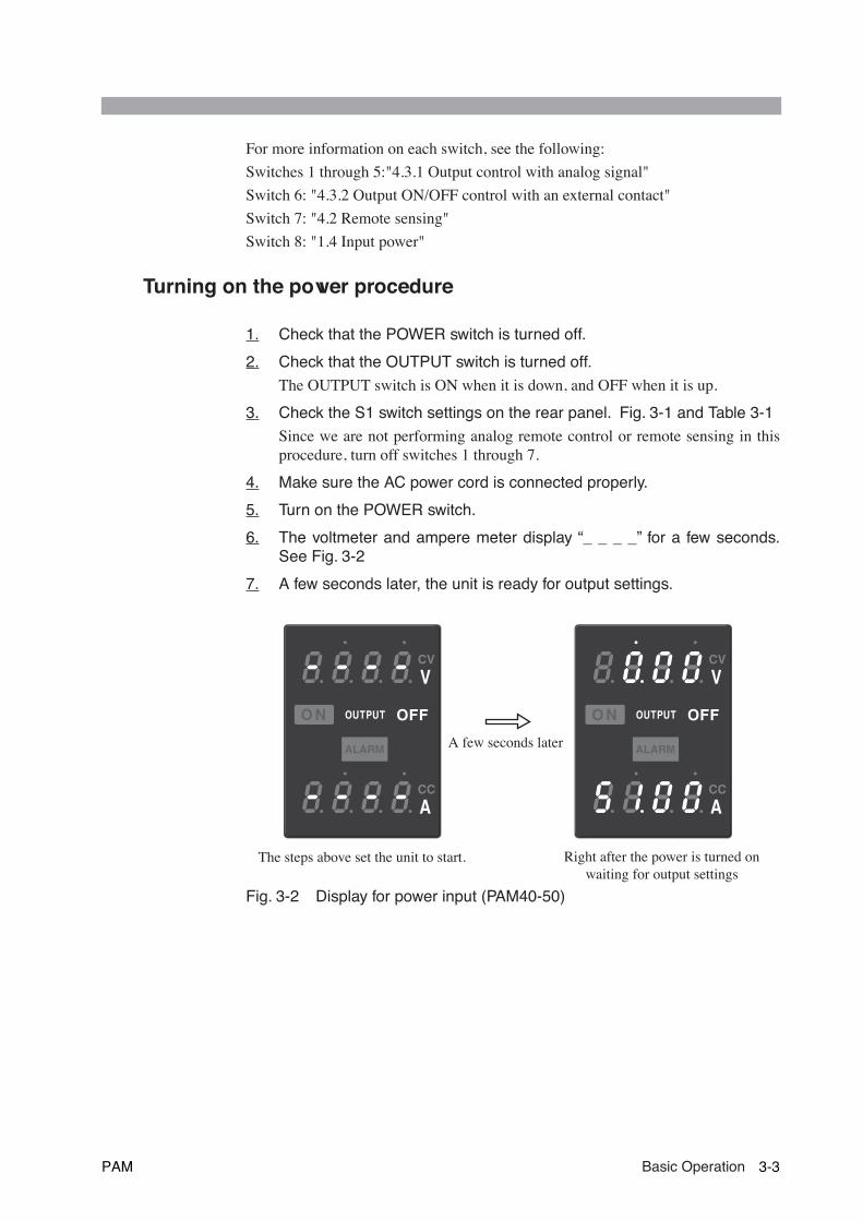
6. The voltmeter and ampere meter display “_ _ _ _” for a few seconds.See Fig. 3-2
7. A few seconds later, the unit is ready for output settings.
Fig. 3-2 Display for power input (PAM40-50)
CC
CV
ALARM
V
A
OFFOUTPUTO N
CC
CV
ALARM
V
A
OFFOUTPUTO N
A few seconds later
The steps above set the unit to start. Right after the power is turned on waiting for output settings
PAM Basic Operation 3-3
3.2 Basic operations
This section explains how to set the output and OVP (Overvoltage Protection) trippoint. It also describes how to use this unit as a constant-voltage power supply orconstant-current power supply.
3.2.1 Setting the output
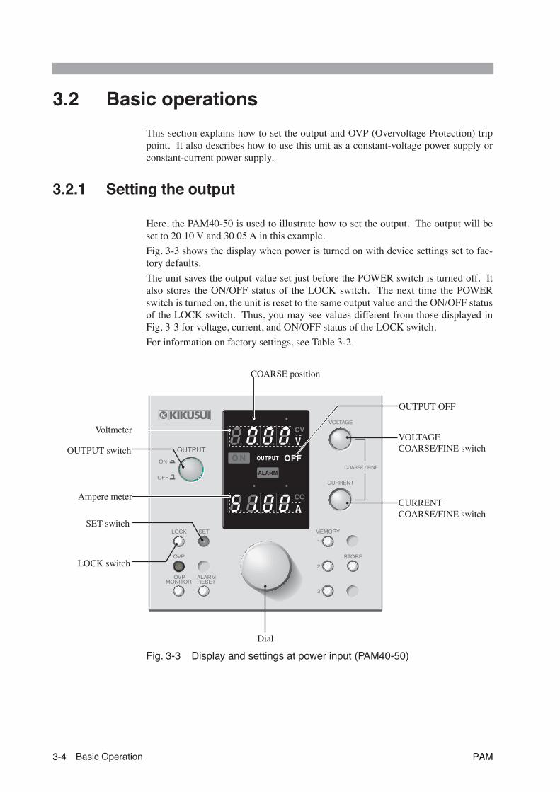
Here, the PAM40-50 is used to illustrate how to set the output. The output will beset to 20.10 V and 30.05 A in this example.
Fig. 3-3 shows the display when power is turned on with device settings set to fac-tory defaults.
The unit saves the output value set just before the POWER switch is turned off. Italso stores the ON/OFF status of the LOCK switch. The next time the POWERswitch is turned on, the unit is reset to the same output value and the ON/OFF statusof the LOCK switch. Thus, you may see values different from those displayed inFig. 3-3 for voltage, current, and ON/OFF status of the LOCK switch.
For information on factory settings, see Table 3-2.
Fig. 3-3 Display and settings at power input (PAM40-50)
O N
ALARM
OUTPUT
V
A
LOCK
1
2
3
MEMORYSET
STORE
CURRENT
VOLTAGE
OVP
COARSE / FINE
OVPMONITOR
ALARMRESET
OUTPUT
ON
OFF
COARSE position
Voltmeter
OUTPUT OFF
OUTPUT switch
Dial
SET switch
LOCK switch
VOLTAGE COARSE/FINE switch
CURRENT COARSE/FINE switch
Ampere meter
3-4 Basic Operation PAM

Table3-2 Factory settings
COARSE/FINEWhen making settings for output voltage and output current on this unit, you mayselect COARSE or FINE.
The COARSE/FINE status is indicated by the two position LED located above thevoltmeter and ampere meter. The left LED lights to indicate COARSE. The rightLED lights to indicate FINE.
Table 3-3 shows the increments in which output can be set in COARSE or FINEmode.
Table3-3 output setting increment
Front panel item Settings
Output voltage setting value 0 V
Output current setting value Maximum value
OUTPUT switch OFF
LOCK switch Light turned off (OFF)
OVP variable resistor Clockwise to a full stop
Memory 1, 2 and 3For three memory units (each output)
Voltage: 0 V, Current: Maximum value
Item on the rear panel Settings
S1 switches1 through 7 OFF
8 OFF
PAM series 2kW model PAM series 4kW model
PAM40-50
PAM80-25
PAM160-12
PAM320-6
PAM40-100
PAM80-50
PAM160-25
PAM20-12
Voltage setting increment [V]
COARSE 1 1 10 10 1 1 10 10
FINE 0.01 0.01 0.1 0.1 0.01 0.01 0.1 0.1
Current setting increment [A]
COARSE 1 1 1 0.1 10 1 1 1
FINE 0.01 0.01 0.01 0.001 0.1 0.01 0.01 0.01
PAM Basic Operation 3-5

Setting PAM40-50 output to 20.10V and 30.05A
1. Check that the LOCK switch is OFF.
If the switch is ON, no output settings can be made.
2. Check that the SET switch is ON.
If it is OFF, the panel displays actual output values.
3. Check that “OUTPUT OFF” is lit on the display.
• If the OUTPUT switch is turned ON, the SET switch, when lit, is automaticallyturned off, and the output values are displayed.
• If the dial is turned with the OUTPUT switch OFF, the SET switch, even whenoff, automatically lights to allow settings to be made.
4. On the voltmeter, check that the COARSE position is lit.
If it is not lit, press VOLTAGE COARSE/FINE switch once.
5. The figure below the COARSE position changes as you turn the dial.Set the dial to “20.” See Fig. 3-4
6. Press the VOLTAGE COARSE/FINE switch.
On the voltmeter, the COARSE position is turned off, and the FINE positionlights.
7. The figure below the FINE position changes as you turn the dial. Setthe dial to “10.”
• Select between COARSE and FINE according to the amplitude of change.
Fig. 3-4 COARSE/FINE position on the voltmeter.
The steps above complete the voltage settings. To proceed to the current settings, goto Step 8.
NOTE
NOTE
CC
CV
ALARM
V
A
OFFOUTPUTO N
CC
CV
ALARM
V
A
OFFOUTPUTO N
FINE position on the voltmeterCOARSE position on the voltmeter
lights lights
3-6 Basic Operation PAM

8. Press the CURRENT COARSE/FINE switch.
On the voltmeter, the FINE position is turned off. On the ampere meter, theCOARSE position lights up. If it is not lit, press CURRENT COARSE/FINE switchonce.
9. The figure below the COARSE position changes as you turn the dial.Set the dial to “30.”
10. Press the CURRENT COARSE/FINE switch.
On the ampere meter, the COARSE position is turned off. On the voltmeter,the FINE position lights up.
11. The figure below the FINE position changes as you turn the dial. Setthe dial to “05.”
• Select between COARSE and FINE according to the amplitude of change.
Fig. 3-5 COARSE/FINE position on the ampere meter
The steps above complete the current settings.
NOTE
CC
CV
ALARM
V
A
OFFOUTPUTO N
CC
CV
ALARM
V
A
OFFOUTPUTO N
FINE position on the ampere meterCOARSE position on the ampere meter
lights lights
PAM Basic Operation 3-7

3.2.2 OVP (OverVoltage Protection) trip point presetting
The overvoltage protection (OVP) function protects a load from unexpectedly highvoltage. If the OVP function is activated, the ALARM LED on the front panel lightsup, and output is shut down. To release the alarm, press the ALARM RESETswitch. In this case, lower the output voltage preset value. Otherwise, the OVPfunction is re-activated when the ALARM RESET switch is pressed.
• To protect the load, preset the OVP trip point for either operation mode.
• The OVP trip point is factory-preset to approx. 110% of the rated outputvoltage of the unit. When using the unit, preset to an OVP trip point suit-able for the load.
• When the unit is used as a constant-voltage power supply with the output currentset to the low level, the OVP circuit may be activated due to a slight overshootcaused when the OUTPUT switch is turned ON. Set the OVP trip point to a valuethat does not activate the OVP function when the OUTPUT switch is turned ON atits maximum working voltage.
• During settings for the OVP trip point (the OVP MONITOR switch is pressed),the last digit place on the voltmeter is fixed to zero.
Fig. 3-6 Settings at OVP
Setting the OVP trip point
To protect the load from an overvoltage, after setting the OVP trip point, apply avoltage larger than the preset voltage between the unit’s output terminals, and checkthat the OVP function works properly.
CAUTION
NOTE
O N
ALARM
OUTPUT
V
A
LOCK
1
2
3
MEMORYSET
STORE
CURRENT
VOLTAGE
OVP
COARSE / FINE
OVPMONITOR
ALARMRESET
OUTPUT
ON
OFF
OUTPUT switch
DialALARM RESETswitch
OVPvariable resistor
OVP MONITORswitch
VOLTAGECOARSE/FINE switch
SET switch
3-8 Basic Operation PAM

The OVP trip point can be set between 20 % to 110 % of the rated output voltage ofthe unit.
When the preset voltage is smaller than the rated output voltage of the unit, you cancheck the performance of the OVP function with the output voltage of the unit.However, if the preset voltage is larger than the rated output voltage, the output volt-age of the unit does not permit verification of OVP performance. In this event, youcan check the OVP function by externally applying a voltage larger than the presetvoltage to the output terminal of the unit. The following describes how to set theOVP trip point below or above the rated output voltage of the unit:
■ Setting the OVP trip point below the rated output voltage of the unit
1. Check that no load is connected to the output terminal.
Following settings for the OVP trip point, OVP operation needs to be checkedby outputting a voltage. Thus, you must remove the load.
2. Check that the OUTPUT switch is OFF.
The OUTPUT switch is ON when it is down, and OFF when it is up.
3. Turn the POWER switch ON.
4. Holding down the OVP MONITOR switch, turn the OVP variable resistorwith a Phillips screwdriver. Set the OVP trip point.
Settings are impossible because the last digit of the OVP trip point value isfixed at 0.
5. Use the VOLTAGE COARSE/FINE switch to select between COARSEand FINE.
6. Turing the dial, set the output voltage to a value well below the OVPvoltage.
7. Press the SET switch to turn it OFF.
When the SET switch is OFF, “0V” appears for the output voltage.
8. Turn the OUTPUT switch ON.
9. Slowly turn the dial clockwise. When the output voltage reaches thepreset OVP voltage, check that ALARM LED lights and the outputs areturned OFF automatically.
The voltmeter displays “OVP” or the current preset value of output voltage.
10. Turn the OUTPUT switch OFF.
11. Press the ALARM RESET switch.
The ALARM LED light goes out.
12. Press the SET switch to turn it ON.
13. Turning the dial counterclockwise, set the output voltage to a value wellbelow the OVP voltage.
The steps above complete the OVP trip point settings.
PAM Basic Operation 3-9

■ Setting the OVP trip point above the rated output voltage of the unit
1. As an external power supply for checking OVP performance, provide apower supply that meets the following conditions:
Output voltage: Above the preset OVP output voltage, with variableoutputs.
Output current: At 5 % above the rated output current of the unit.
No voltmeter is needed for the external power supply, because the externalvoltage can be displayed on the voltmeter of the unit.
2. Check that the POWER switches both on the unit and the externalpower supply are OFF.
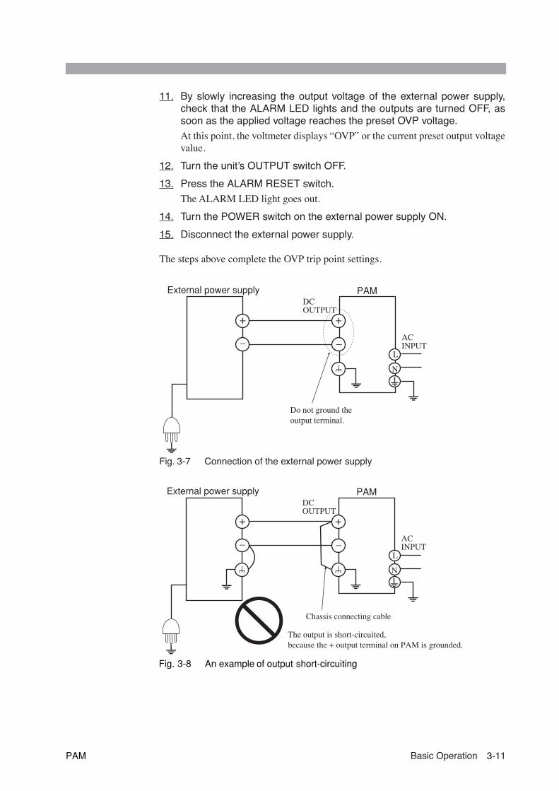
3. As shown in Fig. 3-7, connect the external power supply to the unit’soutput terminal.
For connections to the output terminal, see "3.3.2 Connecting to the output ter-minal"
• Do not ground the unit's output terminal. Otherwise, the external powersupply may short-circuit the output terminal. See Fig. 3-8.When the unit’s output terminal is not grounded, the external power supply
will not short-circuit the output terminal.
4. Check that the OUTPUT switch is OFF.
The OUTPUT switch is ON when it is down, and OFF when it is up.
5. Turn the unit’s POWER switch ON.
6. Holding down the OVP MONITOR switch, turn the OVP variable resistorwith a Phillips screwdriver. Set the OVP trip point.
Settings are impossible because the last digit of the OVP trip point value isfixed at 0. The OVP trip point can be set at up to 110 % of the unit’s rated out-put voltage.
7. Press the SET switch to turn it OFF
The output voltage is displayed while the SET switch is OFF. The externalvoltage is thus displayed.
8. Turn the POWER switch of the external power supply ON.
9. Set the output voltage of the external power supply to a voltage belowthe OVP trip point.
The output voltage of the unit may be set to any value below the OVP presetvoltage.
10. Turn the unit’s OUTPUT switch ON.
• A voltage externally applied to the unit's output terminal must not exceed110% of the preset OVP value. A voltage exceeding the value may cause
damage to the unit.
CAUTION
CAUTION
3-10 Basic Operation PAM
11. By slowly increasing the output voltage of the external power supply,check that the ALARM LED lights and the outputs are turned OFF, assoon as the applied voltage reaches the preset OVP voltage.
At this point, the voltmeter displays “OVP” or the current preset output voltagevalue.
12. Turn the unit’s OUTPUT switch OFF.
13. Press the ALARM RESET switch.
The ALARM LED light goes out.
14. Turn the POWER switch on the external power supply ON.
15. Disconnect the external power supply.
The steps above complete the OVP trip point settings.
Fig. 3-7 Connection of the external power supply
Fig. 3-8 An example of output short-circuiting
++
––
External power supply PAM
Do not ground the output terminal.
ACINPUT
L
N
DCOUTPUT
++
––
Chassis connecting cable
External power supply PAM
The output is short-circuited, because the + output terminal on PAM is grounded.
ACINPUT
L
N
DCOUTPUT
PAM Basic Operation 3-11
3.2.3 Using as a constant voltage power supply
To use the unit as a constant-voltage power supply, take the following steps:
1. Check that the POWER switch is OFF.
2. Check that the OUTPUT switch is OFF.
The OUTPUT switch is OFF when it is down and ON when it is up.
3. Connect a load to the output terminal.
For load connection, see "3.3 Connecting load"
4. Turn the POWER switch ON.
5. Check that “OUTPUT OFF” is lit on the display.
6. Check that the SET switch is lit.
7. Use the CURRENT COARSE/FINE switch to select between COARSEand FINE.
8. Turning the dial, set a current to be applied to the load.
The value set here is the maximum current.
9. Pressing the VOLTAGE COARSE/FINE switch, select between COARSEand FINE.
10. Turning the dial, set a desired voltage.
11. Turn the OUTPUT switch ON.
12. A voltage is output to the output terminal.
CV LED lights.
• When the unit is used as a constant-voltage power supply, the unit shifts to con-stant-current operation once the maximum current set in Step 8 is exceeded due toload fluctuation. CC LED lights when the unit operates at constant current.
NOTE
3-12 Basic Operation PAM
3.2.4 Using as a constant current power supply
To use the unit as a constant-current power supply, take the following steps:
1. Check that the POWER switch is OFF.
2. Check that the OUTPUT switch is OFF.
The OUTPUT switch is OFF when it is down and ON when it is up.
3. Connect a load to the output terminal.
For load connection, see "3.3 Connecting load"
4. Turn the POWER switch ON.
5. Check that “OUTPUT OFF” is lit on the display.
6. Check that the SET switch is lit.
7. Use the VOLTAGE COARSE/FINE switch to select between COARSEand FINE.
8. Turning the dial, set a voltage to be applied to the load.
The value set here is the maximum voltage.
9. Pressing the CURRENT COARSE/FINE switch, select betweenCOARSE and FINE.
10. Turning the dial, set a desired current.
11. Turn the OUTPUT switch ON.
12. A current is output to the output terminal.
CC LED lights.
• When the unit is used as a constant-current power supply, the unit shifts to con-stant-voltage operation once the maximum voltage set in Step 8 is exceeded dueto load fluctuation. CV LED lights when the unit operates at constant voltage.
• When the unit is operating near an output short-circuit, a hissing sound may beheard from inside the unit. This sound does not indicate problems.
NOTE
PAM Basic Operation 3-13

3.3 Connecting load
This section describes the cables (load cables) connecting the unit and a load andthe proper procedure for connecting loads to the output terminals.
3.3.1 load cables
• For load cables, use cables that have sufficient current capacity withrespect to the rated output current of the unit and that have sufficient with-stand voltage with respect to the isolation voltage of the unit.
Current capacity of load cablesLoad cables must be rated to carry the maximum rated output current of the unit. Iftheir current rating exceeds the maximum rated output current, they will carry themaximum current even if a load is short circuited.
The allowable current of a wire is determined by the maximum allowable tempera-ture of the cable insulation, which in turn is governed by a current-caused resistanceloss, ambient temperature, and thermal resistance to the outside. The allowable cur-rents in Table 3-4 show the capacity of current flowing through a heat-resistant PVCwire (single wire) having a maximum allowable temperature of 60 °C when the wireis stretched horizontally in the air at an ambient temperature of 30 °C. If the condi-tion is such that PVC wires with lower heat-resistant temperature are used, ambienttemperature reaches more than 30 °C, or the wires are bundled, resulting in low heatradiation, the current capacity needs to be reduced.
Based on this consideration, it is better to make heat radiation as great as possible tolet a larger current flow, as long as wires having the same heat-resistant temperatureare used. For measures against noise in the load cables, installing the + (pos.) and -(neg.) output lines side by side or bundling them together is more effective againstunnecessary noise. The Kikusui-recommended currents shown in Table 3-4 areallowable current values that have been reduced in consideration of potential bun-dling of load cables. Use these values as a guideline when installing load wires.
Because wires have resistance, voltage drop in wires becomes greater as the wirebecomes longer or the current becomes larger. This causes the voltage applied at theload end to be smaller. The PAM series power supplies have a sensing function thatcompensates for this voltage drop. Compensation of up to approximately 1 V isavailable for a single line. If voltage drop exceeds this level, wires having a greatersectional area should be used.
WARNING
3-14 Basic Operation PAM
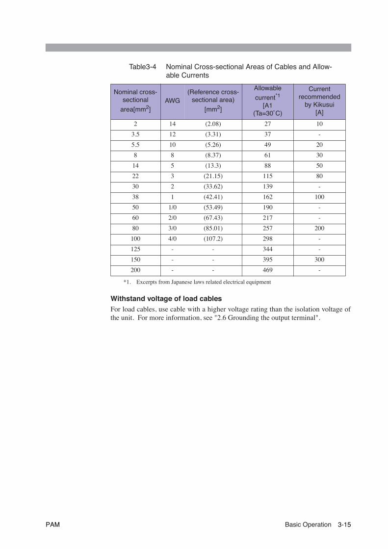
Table3-4 Nominal Cross-sectional Areas of Cables and Allow-able Currents
Withstand voltage of load cablesFor load cables, use cable with a higher voltage rating than the isolation voltage ofthe unit. For more information, see "2.6 Grounding the output terminal".
Nominal cross-sectional
area[mm2]AWG
(Reference cross-sectional area)
[mm2]
Allowable
current*1
[A1(Ta=30˚C)
*1. Excerpts from Japanese laws related electrical equipment
Currentrecommended
by Kikusui[A]
2 14 (2.08) 27 10
3.5 12 (3.31) 37 -
5.5 10 (5.26) 49 20
8 8 (8.37) 61 30
14 5 (13.3) 88 50
22 3 (21.15) 115 80
30 2 (33.62) 139 -
38 1 (42.41) 162 100
50 1/0 (53.49) 190 -
60 2/0 (67.43) 217 -
80 3/0 (85.01) 257 200
100 4/0 (107.2) 298 -
125 - - 344 -
150 - - 395 300
200 - - 469 -
PAM Basic Operation 3-15
3.3.2 Connecting to the output terminal
Models that the rated output current is 25 A or less have two output terminals,located on the front and rear. The output terminal on the front is used as an auxiliaryterminal.
This terminal may not perform ideally, as may be required.
To operate the unit under normal conditions, connect the chassis terminal to the -(neg.) output terminal or to the + (pos.) output terminal, using the accompanyingchassis connecting cable. For more information on the chassis terminal, see "2.6Grounding the output terminal"
Using the DC OUTPUT terminal on the rear
• Models equipped with an auxiliary output terminal have a cover providedfor the terminal. Even when no load is connected to the auxiliary outputterminal, install the cover on the terminal when the unit is in use to ensuresafety. For installation of the auxiliary output terminal cover, see Fig. 3-15
Fig. 3-9 to Fig. 3-13 which are seen in the following procedures show examples ofthe 2kW model. See Fig. 3-9 to Fig. 3-13 for the 4kW model also. Connection to theoutput terminal is the same as the 2kW model.
1. Turn the POWER switch OFF.
2. Remove the DC OUTPUT terminal cover. See Fig. 3-9.
Skip 3 of Fig. 3-9 for the PAM40-50 or PAM40-100 user. The acrylic cover isnot attached for those models.
3. Using the accompanying chassis connecting cable, connect the chassisterminal to the - (neg.) or the + (pos.) output terminal. See Fig. 3-10.
To connect to the output terminal, use the accompanying screws.
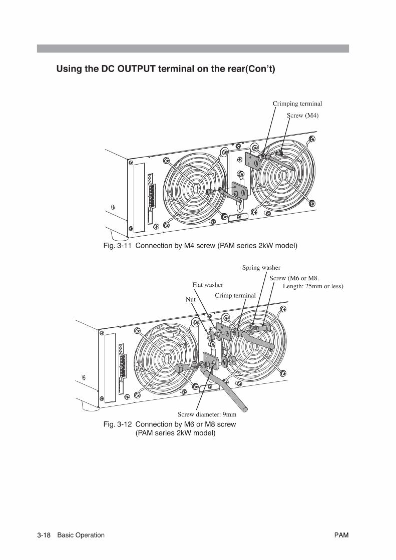
4. Install a crimping terminal on the load cable.
The DC OUTPUT terminal has 9-mm holes and M4 holes for connecting aload cable. For the 9-mm hole, use an M6 or M8 screw. Use a crimping termi-nal compatible with the screw used.
5. Connect the load cable to the DC OUTPUT terminal. See Fig. 3-11 orFig. 3-12.
6. Check that the load cable is connected securely.
7. Install the DC OUTPUT terminal cover. See Fig. 3-13.
Skip 2 of Fig. 3-13 for the PAM40-50 or PAM40-100 user. The acrylic cover isnot attached for those models.
WARNING
3-16 Basic Operation PAM
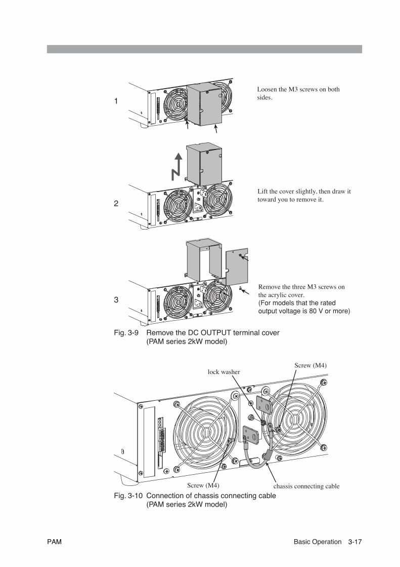
Fig. 3-9 Remove the DC OUTPUT terminal cover (PAM series 2kW model)
Fig. 3-10 Connection of chassis connecting cable (PAM series 2kW model)
Loosen the M3 screws on both sides.
Lift the cover slightly, then draw it toward you to remove it.
Remove the three M3 screws on the acrylic cover.(For models that the rated output voltage is 80 V or more)
1
2
3
lock washerScrew (M4)
Screw (M4) chassis connecting cable
PAM Basic Operation 3-17
Using the DC OUTPUT terminal on the rear(Con’t)
Fig. 3-11 Connection by M4 screw (PAM series 2kW model)
Fig. 3-12 Connection by M6 or M8 screw (PAM series 2kW model)
Screw (M4)
Crimping terminal
Screw (M6 or M8, Length: 25mm or less)
Screw diameter: 9mm
Crimp terminal
Spring washer
Flat washer
Nut
3-18 Basic Operation PAM

Fig. 3-13 Mounting the DC OUTPUT terminal cover (PAM series 2kW model)
Install the cover so that it catches the four screws shown by an arrow. Then fasten two M3 screws at the bottom.
Install the acrylic cover to permit the cable to pass through the slit. Then fasten the cover with three M3 screws.(For models that the rated output voltage is 80 V or more)
1
2
Slits
PAM Basic Operation 3-19

Using the auxiliary output terminal on the front
• Models that the rated output current is 50 A or more have no auxiliary output ter-minal.
In general, to connect a load to the auxiliary output terminal, connect the chassis ter-minal to the - (neg.) or + (pos.) output terminal. For information on connections,see Fig. 3-10.
1. Turn the POWER switch OFF.
2. Install a crimping terminal on the load cable.
The auxiliary output terminal has a diameter of 6 mm. Use a compatiblecrimping terminal.
3. Remove the auxiliary output terminal cover. See Fig. 3-15.
Fig. 3-15 shows an example of the 2kW model. See Fig. 3-15 for the 4kWmodel also. Putting on and taking off the auxiliary output terminal cover arethe same as the 2kW model.
4. Connect the load cable to the auxiliary output terminal. See Fig. 3-14.
5. Install the auxiliary output terminal cover.
Fig. 3-14 Connecting to the auxiliary output terminal on the front panel
Fig. 3-15 Removing and reinstalling the auxiliary output terminal cover(PAM series 2kW model)
NOTE
OUTPUT
+0--80V. 0--25A
Crinp terminal
Auxiliary output terminal cover(Screw diameter: M3)
3-20 Basic Operation PAM

3.4 Memory function
The unit stores up to three preset values for output voltage and current. You canrecall them whenever necessary.
Storing preset values
The preset values for present outputs are stored in memory. Make output settingsbefore starting memory operations.
1. Press the STORE switch.
The MEMORY 1, 2, and 3 switches light.
2. From the above three switches, select and press the one with which youwant to store values.
Only the switch you press remains lit. The preset values for output voltage andcurrent are stored in the memory unit with the selected number.
• To exit STORE mode, turn the dial, or press the STORE switch again. Or donothing for about three seconds to automatically exit STORE mode.
• Memory operations are not possible when the LOCK switch is ON.
Recalling preset values
• If a preset value is recalled from memory with the OUTPUT switch ON, therecalled preset value is output. Thus, note that, if the wrong memory num-ber is selected, the load may be subjected to excessive power levels. Forunused memory units, we recommend presetting a voltage and currentlow enough to protect the load.
1. Press the MEMORY switch with which you want to recall values.
2. The switch you have pressed lights up, and the stored voltage and cur-rent are set.
• To turn the MEMORY switch OFF, turn the dial.
• If a preset value is recalled from memory with the OUTPUT switch ON, outputsmay start about 1.5 second later than usual.
• When the MEMORY switch is pressed with the OUTPUT switch OFF, the SETswitch (if currently off) automatically lights to display the recalled preset values.
NOTE
CAUTION
NOTE
PAM Basic Operation 3-21
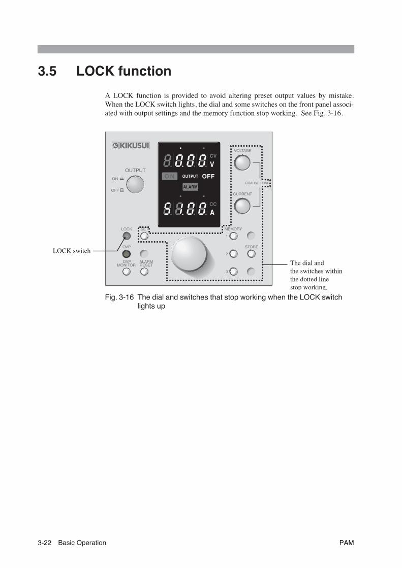
3.5 LOCK function
A LOCK function is provided to avoid altering preset output values by mistake.When the LOCK switch lights, the dial and some switches on the front panel associ-ated with output settings and the memory function stop working. See Fig. 3-16.
Fig. 3-16 The dial and switches that stop working when the LOCK switch lights up
O N
ALARM
OUTPUT
V
A
LOCK
1
2
3
MEMORYSET
STORE
CURRENT
VOLTAGE
OVP
COARSE / FINE
OVPMONITOR
ALARMRESET
OUTPUT
ON
OFF
LOCK switch
The dial andthe switches withinthe dotted linestop working.
3-22 Basic Operation PAM

44
Chapter 4 Applied OperationThis chapter describes the remote sensing, the analog remote control, and remotemonitoring.
PAM Applied Operation 4-1

4.1 General description
The unit permits the following applied operations. The J1 and J2 terminal boardsare used to perform these operations, along with the S1 switch.
• Remote sensing• Output control by analog signal• Output ON/OFF control by external contact• Remote monitoring (Operation mode, Output voltage and Output current)
Fig.4-1 J1,J2 terminal boards and S1 switch(PAM series 2kW model)
6
1
1
2
12
7
1
8
J1
J2
S1
INPUT SELECT
200V 100VOFF
OFF
ON
ON
J1 terminal board
J2 terminal board
S1 switch
4-2 Applied Operation PAM
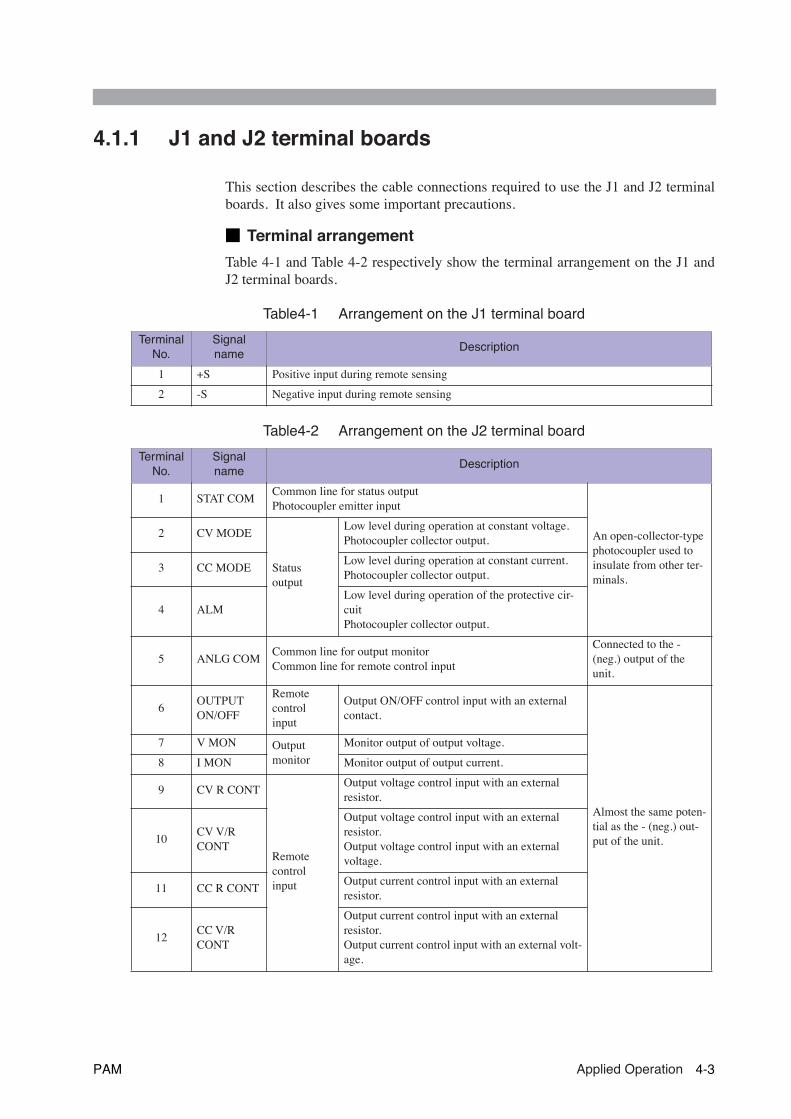
4.1.1 J1 and J2 terminal boards
This section describes the cable connections required to use the J1 and J2 terminalboards. It also gives some important precautions.
■ Terminal arrangement
Table 4-1 and Table 4-2 respectively show the terminal arrangement on the J1 andJ2 terminal boards.
Table4-1 Arrangement on the J1 terminal board
Table4-2 Arrangement on the J2 terminal board
Terminal No.
Signal name
Description
1 +S Positive input during remote sensing
2 -S Negative input during remote sensing
Terminal No.
Signal name
Description
1 STAT COMCommon line for status outputPhotocoupler emitter input
An open-collector-type photocoupler used to insulate from other ter-minals.
2 CV MODE
Status output
Low level during operation at constant voltage.Photocoupler collector output.
3 CC MODELow level during operation at constant current. Photocoupler collector output.
4 ALMLow level during operation of the protective cir-cuitPhotocoupler collector output.
5 ANLG COMCommon line for output monitorCommon line for remote control input
Connected to the - (neg.) output of the unit.
6OUTPUT ON/OFF
Remote control input
Output ON/OFF control input with an external contact.
Almost the same poten-tial as the - (neg.) out-put of the unit.
7 V MON Output monitor
Monitor output of output voltage.
8 I MON Monitor output of output current.
9 CV R CONT
Remote control input
Output voltage control input with an external resistor.
10CV V/R CONT
Output voltage control input with an external resistor.Output voltage control input with an external voltage.
11 CC R CONTOutput current control input with an external resistor.
12CC V/R CONT
Output current control input with an external resistor.Output current control input with an external volt-age.
PAM Applied Operation 4-3
J1 and J2 terminal boards (Con't)
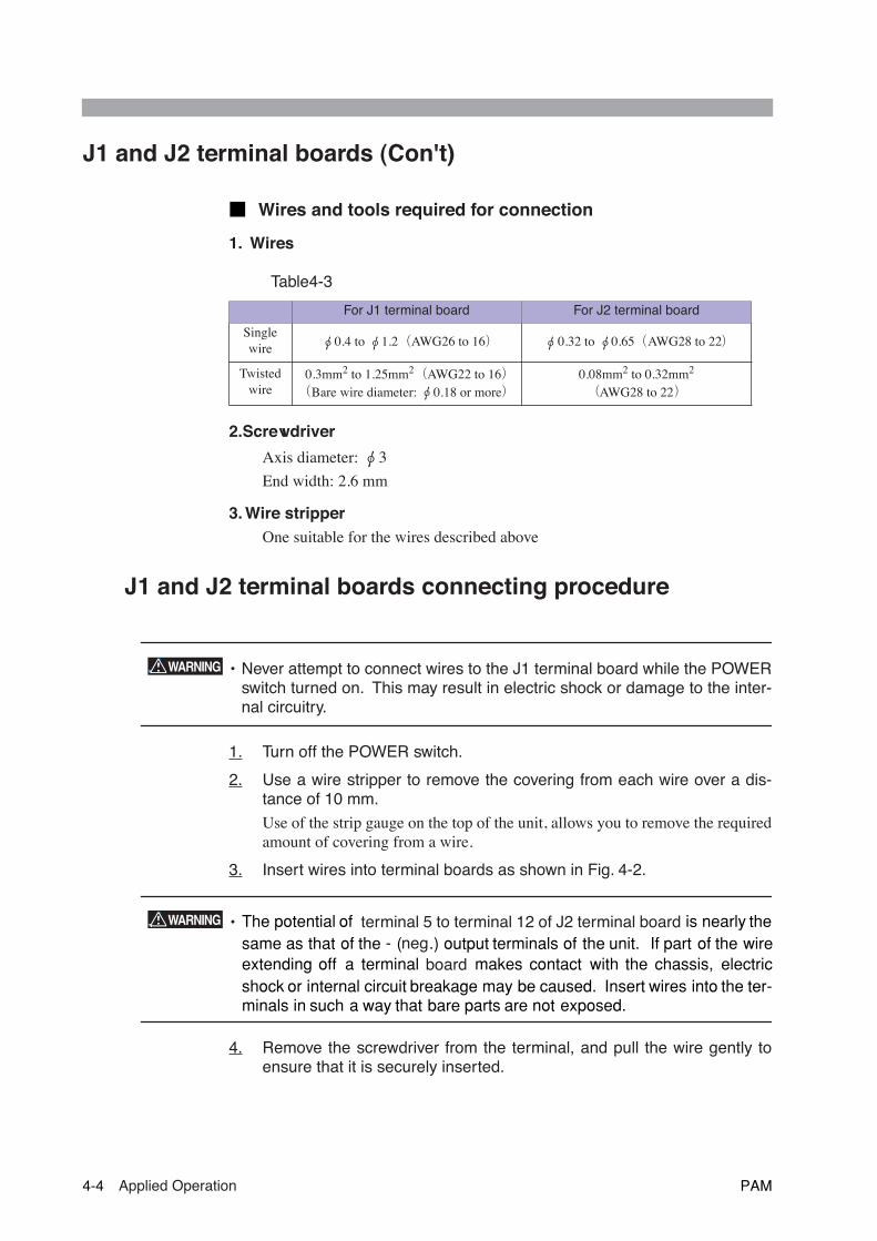
■ Wires and tools required for connection
1. Wires
Table4-3
2.Screwdriver
Axis diameter: φ 3
End width: 2.6 mm
3. Wire stripper
One suitable for the wires described above
J1 and J2 terminal boards connecting procedure
• Never attempt to connect wires to the J1 terminal board while the POWERswitch turned on. This may result in electric shock or damage to the inter-
nal circuitry.
1. Turn off the POWER switch.
2. Use a wire stripper to remove the covering from each wire over a dis-tance of 10 mm.
Use of the strip gauge on the top of the unit, allows you to remove the requiredamount of covering from a wire.
3. Insert wires into terminal boards as shown in Fig. 4-2.
• The potential of terminal 5 to terminal 12 of J2 terminal board is nearly thesame as that of the - ( neg.) output terminals of the unit. If part of the wireextending off a terminal board makes contact with the chassis, electricshock or internal circuit breakage may be caused. Insert wires into the ter-minals in such a way that bare parts are not exposed.
4. Remove the screwdriver from the terminal, and pull the wire gently toensure that it is securely inserted.
For J1 terminal board For J2 terminal board
Single wire φ 0.4 to φ 1.2( AWG26 to 16) φ 0.32 to φ 0.65( AWG28 to 22)
Twisted wire
0.3mm
2
to 1.25mm
2( AWG22 to 16)( Bare wire diameter: φ 0.18 or more)
0.08mm
2
to 0.32mm
2
( AWG28 to 22)
WARNING
WARNING
4-4 Applied Operation PAM
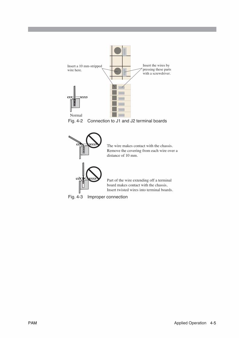
Fig. 4-2 Connection to J1 and J2 terminal boards
Fig. 4-3 Improper connection
Insert the wires by pressing these parts with a screwdriver.
Insert a 10 mm-stripped wire here.
Normal
The wire makes contact with the chassis.Remove the covering from each wire over a distance of 10 mm.
Part of the wire extending off a terminal board makes contact with the chassis,Insert twisted wires into terminal boards.
PAM Applied Operation 4-5

4.1.2 S1 switches
Table 4-4 shows the function of each S1 switch.
Table4-4 Function of S1 switches
*1 The PAM series 4 kW model does not have this function (the line is fixed at 200V, regardless of whether the switch is ON or OFF).
For the function of the No.8 of S1 switch, see "1.4 Input power".
Switch No.
Description ON OFF
1Mode selection for output voltage control with an external resistor 10 kΩ→ 0 OUT mode 10 kΩ→ MAX OUT mode
2Selection of program sources for output voltage control
External resistor Voltage
3Mode selection for output current control with an external resistor 10 kΩ→ 0 OUT mode 10 kΩ→ MAX OUT mode
4Selection of program sources for output current control
External resistor Voltage
5 Selection of remote control Remote control Local control
6 Mode selection for OUTPUT ON/OFF Close ON mode Close OFF mode
7 Selection of remote sensing Remote sensing Local sensing
8 Selection of input voltage (*1) 200 V 100 V
NOTE
4-6 Applied Operation PAM
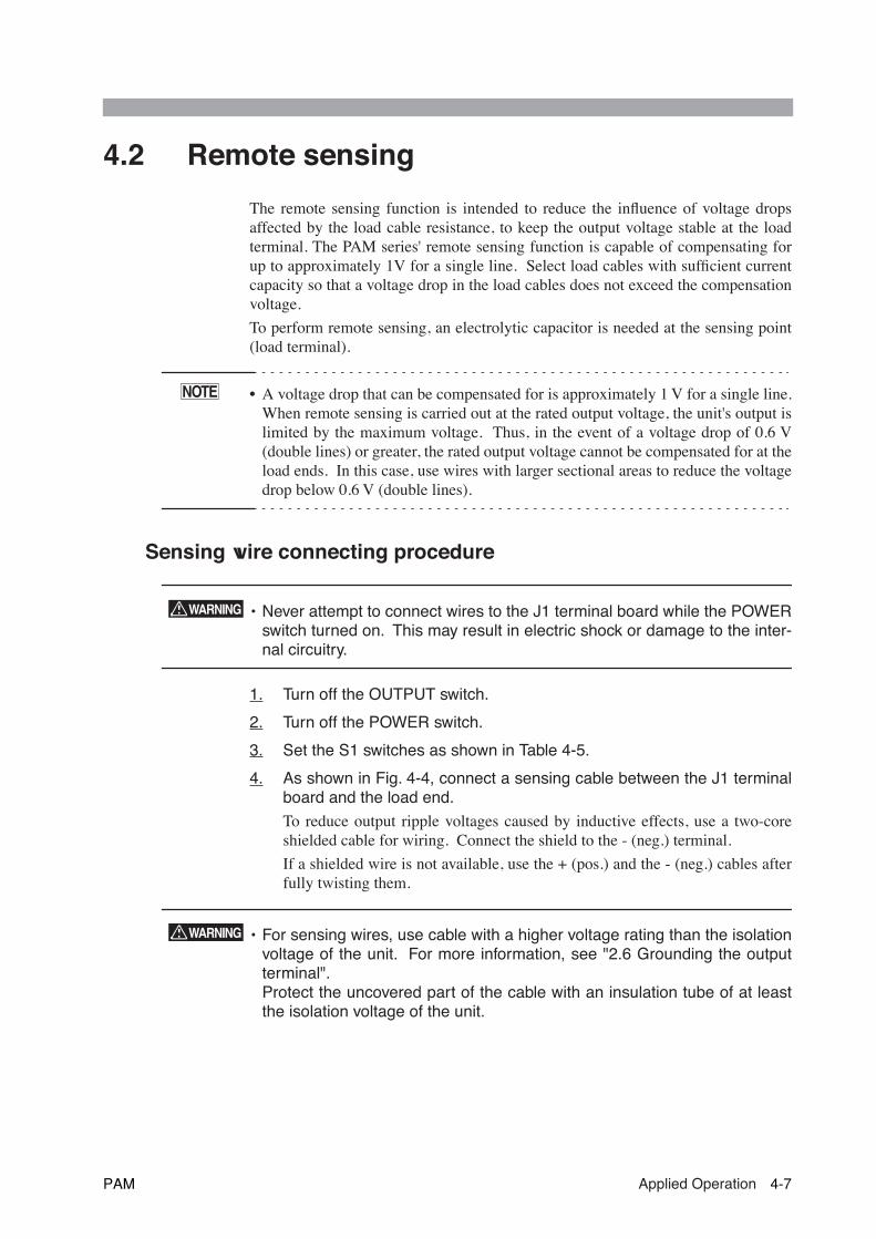
4.2 Remote sensing
The remote sensing function is intended to reduce the influence of voltage dropsaffected by the load cable resistance, to keep the output voltage stable at the loadterminal. The PAM series' remote sensing function is capable of compensating forup to approximately 1V for a single line. Select load cables with sufficient currentcapacity so that a voltage drop in the load cables does not exceed the compensationvoltage.
To perform remote sensing, an electrolytic capacitor is needed at the sensing point(load terminal).
• A voltage drop that can be compensated for is approximately 1 V for a single line.When remote sensing is carried out at the rated output voltage, the unit's output islimited by the maximum voltage. Thus, in the event of a voltage drop of 0.6 V(double lines) or greater, the rated output voltage cannot be compensated for at theload ends. In this case, use wires with larger sectional areas to reduce the voltagedrop below 0.6 V (double lines).
Sensing wire connecting procedure
• Never attempt to connect wires to the J1 terminal board while the POWERswitch turned on. This may result in electric shock or damage to the inter-nal circuitry.
1. Turn off the OUTPUT switch.
2. Turn off the POWER switch.
3. Set the S1 switches as shown in Table 4-5.
4. As shown in Fig. 4-4, connect a sensing cable between the J1 terminalboard and the load end.
To reduce output ripple voltages caused by inductive effects, use a two-coreshielded cable for wiring. Connect the shield to the - (neg.) terminal.
If a shielded wire is not available, use the + (pos.) and the - (neg.) cables afterfully twisting them.
• For sensing wires, use cable with a higher voltage rating than the isolationvoltage of the unit. For more information, see "2.6 Grounding the outputterminal". Protect the uncovered part of the cable with an insulation tube of at leastthe isolation voltage of the unit.
NOTE
WARNING
WARNING
PAM Applied Operation 4-7

Sensing wire connecting procedure (Cont’d)
• If the sensing wire is disconnected, the output voltage at the load terminalscannot be stabilized, and excessive voltage may be applied to the load.Use crimp terminals for securely connections.
• To turn on/off the power supplied to a load using a mechanical switch, pro-vide additional switches between the sensing wires as shown in Fig. 4-5;turn on/off the power and remote sensing function simultaneously.
5. Connect an electrolytic capacitor (C) with a capacity of approx. 0.1 μFto 100 μF across the load terminals.
• Use a capacitor (C) whose withstand voltage is 120 % or more of the unit'srated output voltage.
• If the length of wiring to a load extends to 3 m or more, the phase shift caused bythe inductance and capacitance of the wiring becomes non-negligible, therebycausing oscillation. In such cases, the capacitor (C) prevents oscillation.
• If the load current changes suddenly to pulse form, the output voltage mayincrease due to effects from the inductance components of the wiring. In suchcases, the capacitor (C) also prevents variations in output.
• Twisting the load cable reduces inductive effects and stabilizes operations.
6. Recheck that the connections of terminal and setting of switches.
• After using remote sensing, disconnect the sensing wires and turn OFFthe No. 7 of S1 switch.
• Never attempt to turn ON/OFF the No.7 of S1 switch while the POWERswitch turned on.
CAUTION
CAUTION
NOTE
CAUTION
4-8 Applied Operation PAM
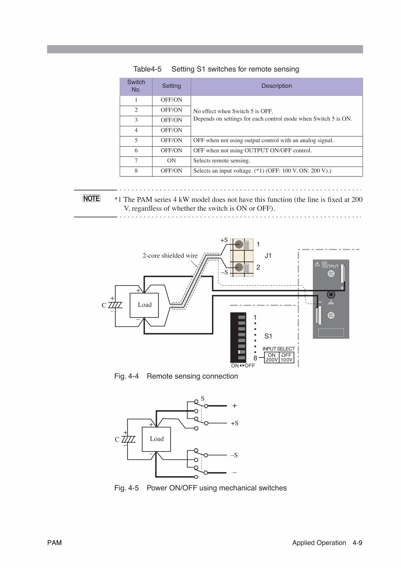
Table4-5 Setting S1 switches for remote sensing
*1 The PAM series 4 kW model does not have this function (the line is fixed at 200V, regardless of whether the switch is ON or OFF).
Fig. 4-4 Remote sensing connection
Fig. 4-5 Power ON/OFF using mechanical switches
Switch No.
Setting Description
1 OFF/ON
No effect when Switch 5 is OFF.Depends on settings for each control mode when Switch 5 is ON.
2 OFF/ON
3 OFF/ON
4 OFF/ON
5 OFF/ON OFF when not using output control with an analog signal.
6 OFF/ON OFF when not using OUTPUT ON/OFF control.
7 ON Selects remote sensing.
8 OFF/ON Selects an input voltage (*1) (OFF: 100 V, ON: 200 V).)
NOTE
1
2
J1DCOUTPUT
1
8
S1
INPUT SELECT
200V 100VOFF
OFF
ON
ON
Load
2-core shielded wire
+S
–S
++
––
C
Load
S
+
–C
+
–
+S
–S
+
–
PAM Applied Operation 4-9
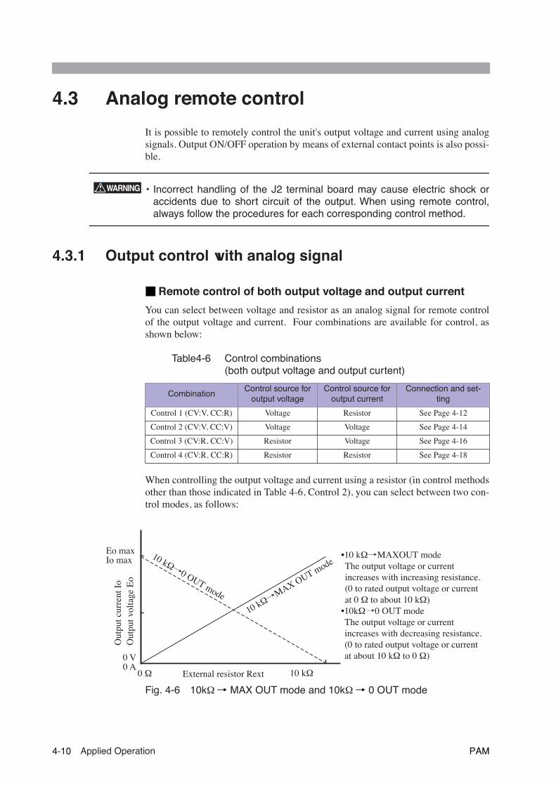
4.3 Analog remote control
It is possible to remotely control the unit's output voltage and current using analogsignals. Output ON/OFF operation by means of external contact points is also possi-ble.
• Incorrect handling of the J2 terminal board may cause electric shock oraccidents due to short circuit of the output. When using remote control,always follow the procedures for each corresponding control method.
4.3.1 Output control with analog signal
■ Remote control of both output voltage and output current
You can select between voltage and resistor as an analog signal for remote controlof the output voltage and current. Four combinations are available for control, asshown below:
Table4-6 Control combinations (both output voltage and output curtent)
When controlling the output voltage and current using a resistor (in control methodsother than those indicated in Table 4-6, Control 2), you can select between two con-trol modes, as follows:
Fig. 4-6 10k
Ω→ MAX OUT mode and 10k Ω→ 0 OUT mode
CombinationControl source for
output voltageControl source for
output current Connection and set-
ting
Control 1 (CV:V, CC:R) Voltage Resistor See Page 4-12
Control 2 (CV:V, CC:V) Voltage Voltage See Page 4-14
Control 3 (CV:R, CC:V) Resistor Voltage See Page 4-16
Control 4 (CV:R, CC:R) Resistor Resistor See Page 4-18
WARNING
Eo maxIo max
0 V0 A
0 Ω 10 kΩExternal resistor Rext
10 kΩ→MAX OUT mode
10 kΩ→0 OUT mode
Out
put c
urre
nt I
oO
utpu
t vol
tage
Eo
•10 kΩ→MAXOUT modeThe output voltage or current increases with increasing resistance.(0 to rated output voltage or current at 0 Ω to about 10 kΩ)
•10kΩ→0 OUT modeThe output voltage or current increases with decreasing resistance.(0 to rated output voltage or current at about 10 kΩ to 0 Ω)
4-10 Applied Operation PAM
■ Remote control of either output voltage or output current
This unit does not have a function to allow analog remote control of the output volt-age or the output current alone. However, either the output voltage or the outputcurrent alone may be temporarily remote-controlled by replacing the resistor in thecontrol source with a jumper cable.
When using a jumper cable, the external resistance becomes almost 0
Ω
. For thisreason, it is necessary to change the resistance control mode from 10 k
Ω
to 0
Ω
OUT. Thus, where voltage or current is not remote-controlled, set to the rated out-put.
Table4-7 Control combination (either output voltage or output current alone)
Connecting and setting procedure
• Never attempt to connect wires to the J2 terminal board while the POWERswitch turned on. This may result in electric shock or damage to the inter-nal circuitry.
• The potential of terminal 5 to terminal 12 of J2 terminal board is nearly thesame as that of the - ( neg.) output terminals of the unit. If part of the wireextending off a terminal board makes contact with the chassis, electricshock or internal circuit breakage may be caused. Insert wires into the ter-minals in such a way that bare parts are not exposed.
1. Turn off the OUTPUT switch.
2. Turn off the POWER switch.
3. From Table 4-6 and Table 4-7, select the desired control method.
4. Set the S1 switches and connect the control source according to thesettings and connections for each control method shown in the follow-ing pages.
5. Recheck the terminal-board connections and switch settings.
CombinationControl source for
output voltageControl source for
output current Connection and setting
Control 5 (CV:V, CC:Irtg) Voltage Jumper (0
Ω
) See Page 4-20
Control 6 (CV:R, CC:Irtg) Resistor Jumper (0
Ω
) See Page 4-22
Control 7 (CV:Ertg, CC:V) Jumper (0
Ω
) Voltage See Page 4-24
Control 8 (CV:Ertg, CC:R) Jumper (0
Ω
) Resistor See Page 4-26
WARNING
PAM Applied Operation 4-11

Control 1 (CV:V, CC:R), connection and setting
Table4-8 Setting S1 switches for Control 1
*1 The PAM series 4 kW model does not have this function (the line is fixed at 200V, regardless of whether the switch is ON or OFF).
Fig. 4-7 Connection for Control 1
Switch No. Settings Description
1 OFF/ON No effects on Control 1
2 OFF Selects voltage as control source for output voltage
3OFF 10 kΩ→ MAX OUT mode
ON 10 k
Ω→ 0 OUT mode
4 ON Selects resistor as control source for output current
5 ON Selects output control with analog signal
6 OFF/ON OFF when not using OUTPUT ON/OFF control
7 OFF/ON OFF when not using remote sensing
8 OFF/ON Selects an input voltage (*1) (OFF: 100 V, ON: 200 V)
NOTE
6
1
12
7J2
DCOUTPUT
1
8
S1
INPUT SELECT
200V 100VOFF
OFF
ON
ON
2-core shielded wireor twisted-pair wire
Output voltage Eo
Vext
Eo ≈ Ertg ・Vext
10 [V]
0 ≤ Vext ≤ 10.5[V]Ertg:Rated output voltage [V]
Rext
10 kΩ→MAX OUT mode
Io ≈ Irtg ・Rext 10000 [A]
Rext ≤10000 [Ω]Irtg:Rated output current [A]
10 kΩ→ 0 OUT mode
Io ≈ 10000 - Rext 10000 ・Irtg [A]
Output current Io
+
–
5
101112
Output voltage setting
Output current setting
For Vext and Rext, set the voltage and resistance values well above the minimum level.
4-12 Applied Operation PAM
• Insulate the external voltage source (Vext), an external resistance (Rext)and the cable connected to it with at least the isolation voltage of the unit.Float Vext outputs instead of grounding them (floating). For details, see"2.6 Grounding the output terminal"
• When using a shielded cable for the connection, protect the uncoveredpart of the cable with an insulation tube of at least the isolation voltage ofthe unit.
• Watch the polarity of Vext. Connection at incorrect polarity may damagethe unit.
• If Vext is disconnected, an unexpected voltage may be supplied by exter-nal noise. Connect Vext securely to the J2 terminal board.
• Do not apply a reverse voltage or a voltage of 10.5V or greater betweenterminal 5 and terminal 10 of the J2 terminal board. Doing so will damagethe unit.
• In the 10k Ω → MAX OUT mode, if Rext is disconnected, an excessivelylarge current can flow to the load. Connect Rext securely to the J2 termi-nal board. If there is any danger of Rext being cut off and the circuitopened, use the 10k
Ω
→ 0 OUT mode.
• To use a fixed resistor for Rext and to control it with a switch, select a
closed short-circuit or continuous switch.
• To reduce the effects of noise on output, use a 2-core shielded wire or a twisted-pair wire to connect between Vext and J2 terminal board and between Rext and J2terminal board, making them as short as possible.Longer wiring results in greater susceptibility to the effects of noise, and use ofcables with antinoise measures may not solve the problem, resulting in improperoperation.When using a shielded wire, connect the shield to the - (neg.) output terminal.For information on connecting the shield to the Vext side, see Page 4-28 "Whenyou wish to connect the shield to Vext"
• The input impedance between terminal 5 and terminal 10 of the J2 terminal boardis approximately 10 k
Ω
.
• For Vext, use a voltage source of low noise and good stability. Noise in Vext ismultiplied by the amplification degree of the unit and appears in the unit's output.Thus, output ripple noise may not meet the unit's specifications.
• For Rext, use a 1/2 W or larger resistor that has a good temperature coefficient andminimal aging effects, such as a metal film resistor or wire-wound resistor.
• Fig. 4-7 shows the general relationship between Vext and the output voltage Eoand between Rext and output current Io. But since they are approximate formu-las, if you need precise zero and maximum values for output values, adjust the
Vext and Rext values (Io applied to the 10 k
Ω
→ 0 OUT mode).
WARNING
CAUTION
NOTE
PAM Applied Operation 4-13

Control 2 (CV:V, CC:V), connection and setting
Table4-9 Setting S1 switches for Control 2
*1 The PAM series 4 kW model does not have this function (the line is fixed at 200V, regardless of whether the switch is ON or OFF).
Fig. 4-8 Connection for Control 2
Switch No. Settings Description
1 OFF/ON No effects on Control 2
2 OFF Selects voltage as control source for output voltage
3 OFF/ON No effects on Control 2
4 OFF Selects voltage as control source for output current
5 ON Selects output control with analog signal
6 OFF/ON OFF when not using OUTPUT ON/OFF control
7 OFF/ON OFF when not using remote sensing
8 OFF/ON Selects an input voltage (*1) (OFF: 100 V, ON: 200 V)
NOTE
6
1
12
7J2
DCOUTPUT
1
8
S1
INPUT SELECT
200V 100VOFF
OFF
ON
ON
Output voltage Eo
Eo ≈ Ertg ・Vext1
10 [V]
0 ≤ Vext1 ≤ 10.5[V]Ertg:Rated output voltage [V]
Output current Io
Io ≈ Irtg ・Vext2
10 [A]
0 ≤ Vext 2 ≤ 10.5[V]Irtg:Rated output current [A]
3-core shielded wireor twisted-paire wire
Vext1+
–
Vext2+
–
5
10
12
Connect - (neg.) output of Vext1 and Vext2, Common line is turned into one with Vext side.
Output voltage setting
Output current setting
For Vext1 and Vext2, set the voltage value well above the minimum level.
4-14 Applied Operation PAM
• Insulate the external voltage source (Vext), an external resistance (Rext)and the cable connected to it with at least the isolation voltage of the unit.Float Vext outputs instead of grounding them (floating). For details, see"2.6 Grounding the output terminal"
• When using a shielded cable for the connection, protect the uncoveredpart of the cable with an insulation tube of at least the isolation voltage ofthe unit.
• Watch the polarity of Vext. Connection at incorrect polarity may damagethe unit.
• If Vext is disconnected, an unexpected voltage may be supplied by exter-nal noise. Connect Vext securely to the J2 terminal board.
• Do not apply a reverse voltage or a voltage of 10.5V or greater betweenterminal 5 and terminal 10 and between terminal 5 and terminal 12 of theJ2 terminal board. Doing so will damage the unit.
• To reduce the effects of noise on output, use a 3-core shielded wire or a twisted-pair wire to connect betreen Vext and J2 terminal board, making them as short aspossible.Longer wiring results in greater susceptibility to the effects of noise, and use ofcables with antinoise measures may not solve the problem, resulting in improperoperation.When using a shielded wire, connect the shield to the - (neg.) output terminal.For information on connecting the shield to the Vext side, see Page 4-28 "Whenyou wish to connect the shield to Vext"
• The input impedance between terminal 5 and terminal 10 and between terminal 5and terminal 12 of the J2 terminal board is approximately 10 kΩ.
• For Vext, use a voltage source of low noise and good stability. Noise in Vext ismultiplied by the amplification degree of the unit and appears in the unit's output.Thus, output ripple noise may not meet the unit's specifications.
• Fig. 4-8 shows the general relationship between Vext1 and the output voltage Eoand between Vext2 and the output current Io. But since they are approximate for-mulas, if you need precise zero and maximum values for output values, adjust theVext1 and Vext2 values.
WARNING
CAUTION
NOTE
PAM Applied Operation 4-15
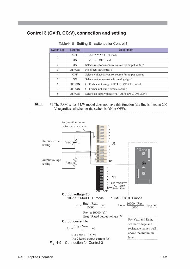
Control 3 (CV:R, CC:V), connection and setting
Table4-10 Setting S1 switches for Control 3
*1 The PAM series 4 kW model does not have this function (the line is fixed at 200V, regardless of whether the switch is ON or OFF).
Fig. 4-9 Connection for Control 3
Switch No. Settings Description
1OFF 10 kΩ→ MAX OUT mode
ON 10 k
Ω→ 0 OUT mode
2 ON Selects resistor as control source for output voltage
3 OFF/ON No effects on Control 3
4 OFF Selects voltage as control source for output current
5 ON Selects output control with analog signal
6 OFF/ON OFF when not using OUTPUT ON/OFF control
7 OFF/ON OFF when not using remote sensing
8 OFF/ON Selects an input voltage (*1) (OFF: 100 V, ON: 200 V)
NOTE
6
1
12
7J2
DCOUTPUT
1
8
S1
INPUT SELECT
200V 100VOFF
OFF
ON
ON
Output voltage Eo10 kΩ→MAX OUT mode
Eo ≈ Ertg ・Rext 10000 [V]
Rext ≤ 10000 [Ω]Ertg:Rated output voltage [V]
10 kΩ→ 0 OUT mode
Eo ≈ 10000 - Rext 10000 ・Ertg [V]
Output current Io
Io ≈ Irtg ・Vext
10 [A]
0 ≤ Vext ≤ 10.5[V]Irtg:Rated output current [A]
2-core silded wireor twisted-pair wire
Vext
Rext
+
–
5
910
12
Output currentsetting
Output voltagesetting
For Vext and Rext, set the voltage and resistance values well above the minimum level.
4-16 Applied Operation PAM
• Insulate the external voltage source (Vext), an external resistance (Rext)and the cable connected to it with at least the isolation voltage of the unit.Float Vext outputs instead of grounding them (floating). For details, see"2.6 Grounding the output terminal"
• When using a shielded cable for the connection, protect the uncoveredpart of the cable with an insulation tube of at least the isolation voltage ofthe unit.
• Watch the polarity of Vext. Connection at incorrect polarity may damagethe unit.
• If Vext is disconnected, an unexpected voltage may be supplied by exter-nal noise. Connect Vext securely to the J2 terminal board.
• Do not apply a reverse voltage or a voltage of 10.5V or greater betweenterminal 5 and terminal 10 of the J2 terminal board. Doing so will damagethe unit.
• In the 10 kΩ → MAX OUT mode, if Rext is disconnected, an excessivelylarge current can flow to the load. Connect Rext securely to the J2 termi-nal board. If there is any danger of Rext being cut off and the circuitopened, use the 10 k
Ω
→ 0 OUT mode.
• To use a fixed resistor for Rext and to control it with a switch, select a
closed short-circuit or continuous switch.
• To reduce the effects of noise on output, use a 2-core shielded wire or a twisted-pair wire to connect between Vext and J2 terminal board and between Rext and J2terminal board, making them as short as possible.Longer wiring results in greater susceptibility to the effects of noise, and use ofcables with antinoise measures may not solve the problem, resulting in improperoperation.When using a shielded wire, connect the shield to the - (neg.) output terminal.For information on connecting the shield to the Vext side, see Page 4-28 "Whenyou wish to connect the shield to Vext"
• The input impedance between terminal 5 and terminal 12 of the J2 terminal boardis approximately 10 k
Ω
.
• For Vext, use a voltage source of low noise and good stability. Noise in Vext ismultiplied by the amplification degree of the unit and appears in the unit's output.Thus, output ripple noise may not meet the unit's specifications.
• For Rext, use a 1/2 W or larger resistor that has a good temperature coefficient andminimal aging effects, such as a metal film resistor or wire-wound resistor.
• Fig. 4-9 shows the general relationship between Vext and the output current Io andbetween Rext and output voltage Eo. But since they are approximate formulas, ifyou need precise zero and maximum values for output values, adjust the Vext and
Rext values (Eo applied to the 10 k
Ω
→ 0 OUT mode).
WARNING
CAUTION
NOTE
PAM Applied Operation 4-17
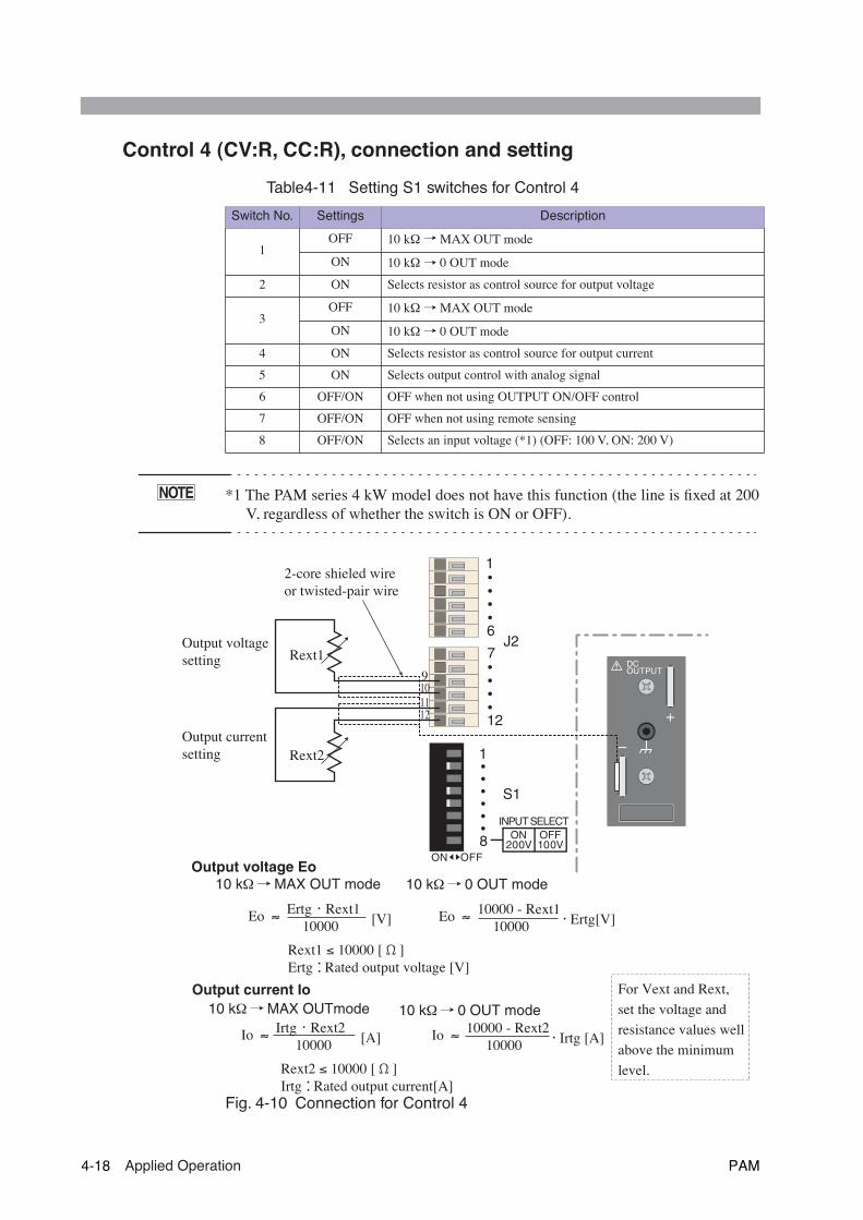
Control 4 (CV:R, CC:R), connection and setting
Table4-11 Setting S1 switches for Control 4
*1 The PAM series 4 kW model does not have this function (the line is fixed at 200V, regardless of whether the switch is ON or OFF).
Fig. 4-10 Connection for Control 4
Switch No. Settings Description
1OFF 10 kΩ→ MAX OUT mode
ON 10 k
Ω→ 0 OUT mode
2 ON Selects resistor as control source for output voltage
3OFF 10 k
Ω→ MAX OUT mode
ON 10 k
Ω→ 0 OUT mode
4 ON Selects resistor as control source for output current
5 ON Selects output control with analog signal
6 OFF/ON OFF when not using OUTPUT ON/OFF control
7 OFF/ON OFF when not using remote sensing
8 OFF/ON Selects an input voltage (*1) (OFF: 100 V, ON: 200 V)
NOTE
6
1
12
7J2
DCOUTPUT
1
8
S1
INPUT SELECT
200V 100VOFF
OFF
ON
ON
2-core shieled wireor twisted-pair wire
Output voltage Eo10 kΩ→MAX OUT mode
Eo ≈ Ertg ・Rext1 10000 [V]
Rext1 ≤ 10000 [Ω]Ertg:Rated output voltage [V]
10 kΩ→ 0 OUT mode
Eo ≈ 10000 - Rext1 10000 ・Ertg[V]
10 kΩ→MAX OUTmode
Io ≈ Irtg ・Rext2 10000 [A]
Rext2 ≤ 10000 [Ω]Irtg:Rated output current[A]
10 kΩ→ 0 OUT mode
Io ≈ 10000 - Rext2 10000 ・Irtg [A]
Output current Io
Rext2
Rext1
9101112
Output voltagesetting
Output currentsetting
For Vext and Rext, set the voltage and resistance values well above the minimum level.
4-18 Applied Operation PAM

• Insulate the external resistance (Rext) and the cable connected to it with atleast the isolation voltage of the unit. Float Vext outputs instead of ground-ing them (floating). For details, see "2.6 Grounding the output terminal"
• When using a shielded cable for the connection, protect the uncoveredpart of the cable with an insulation tube of at least the isolation voltage ofthe unit.
• In the 10 kΩ → MAX OUT mode, if Rext is disconnected, an excessivelylarge current can flow or excessively large voltage can output to the load.Connect Rext securely to the J2 terminal board.
If there is any danger of Rext being cut off and the circuit opened, use the10 k
Ω
→ 0 OUT mode.
• To use a fixed resistor for Rext and to control it with a switch, select a
closed short-circuit or continuous switch.
• To reduce the effects of noise on output, use a 2-core shielded wire or atwisted-pair wire to connect between Rext and J2 terminal board, makingthem as short as possible.Longer wiring results in greater susceptibility to the effects of noise, anduse of cables with antinoise measures may not solve the problem, result-ing in improper operation.When using a shielded wire, connect the shield to the - (neg.) output termi-nal.
• For Rext, use a 1/2 W or larger resistor that has a good temperature coefficient andminimal aging effects, such as a metal film resistor or wire-wound resistor.
• Fig. 4-10 shows the general relationship between Rext1 and the output voltage Eoand between Rext2 and output current Io. But since they are approximate formu-las, if you need precise zero and maximum values for output values, adjust the
Rext1 and Rext2 values (Eo and Io applied to the 10 k
Ω
→ 0 OUT mode).
WARNING
CAUTION
NOTE
PAM Applied Operation 4-19

Control 5 (CV:V, CC:Irtg), connection and setting
Table4-12 Setting S1 switches for Control 5
*1 The PAM series 4 kW model does not have this function (the line is fixed at 200V, regardless of whether the switch is ON or OFF).
Fig. 4-11 Connection for Control 5
Switch No. Settings Description
1 OFF/ON No effects on Control 5
2 OFF Selects voltage as control source for output voltage
3 ON 10 kΩ→ 0 OUT mode
4 ON Selects resistor as control source for output current
5 ON Selects output control with analog signal
6 OFF/ON OFF when not using OUTPUT ON/OFF control
7 OFF/ON OFF when not using remote sensing
8 OFF/ON Selects an input voltage (*1) (OFF: 100 V, ON: 200 V)
NOTE
6
1
12
7J2
DCOUTPUT
1
8
S1
INPUT SELECT
200V 100VOFF
OFF
ON
ON
Output current: Fixed at the rated output current.
Jumper
Vext+
–
5
101112
2-core silded wireor twisted-pair wire
Output voltagesetting
Output voltage Eo
Eo ≈ Ertg ・Vext 10 [V]
0 ≤Vext ≤ 10.5 [V]Ertg:Rated output voltage [V]
Output current Io
Io ≈ 10000 - Rext ・ Irtg
10000 [A]
Rext = 0 [Ω]Irtg:Rated output current [A]
For Vext, set the voltage value well above the minimum level.
10 kΩ→0 OUT mode
4-20 Applied Operation PAM

• Insulate the external voltage source (Vext), the Jumper and the cable con-nected to it with at least the isolation voltage of the unit. Float Vext outputsinstead of grounding them (floating). For details, see "2.6 Grounding theoutput terminal"
• When using a shielded cable for the connection, protect the uncoveredpart of the cable with an insulation tube of at least the isolation voltage ofthe unit.
• Watch the polarity of Vext. Connection at incorrect polarity may damagethe unit.
• If Vext is disconnected, an unexpected voltage may be supplied by exter-nal noise. Connect Vext securely to the J2 terminal board.
• Do not apply a reverse voltage or a voltage of 10.5V or greater betweenterminal 5 and terminal 10 of the J2 terminal board. Doing so will damagethe unit.
• To reduce the effects of noise on output, use a 2-core shielded wire or a twisted-pair wire to connect between Vext and J2 terminal board, making them as short aspossible.Longer wiring results in greater susceptibility to the effects of noise, and use ofcables with antinoise measures may not solve the problem, resulting in improperoperation.When using a shielded wire, connect the shield to the - (neg.) output terminal.For information on connecting the shield to the Vext side, see Page 4-28 "Whenyou wish to connect the shield to Vext"
• The input impedance between terminal 5 and terminal 10 of the J2 terminal boardis approximately 10 kΩ.
• For Vext, use a voltage source of low noise and good stability. Noise in Vext ismultiplied by the amplification degree of the unit and appears in the unit's output.Thus, output ripple noise may not meet the unit's specifications.
• Fig. 4-11 shows the general relationship between Vext and output voltage Eo andbetween Rext and the output current Io. But since they are approximate formulas,if you need precise zero and maximum values for output values, adjust the Vextand Rext values .
WARNING
CAUTION
NOTE
PAM Applied Operation 4-21

Control 6 (CV:R, CC:Irtg), connection and setting
Table4-13 Setting S1 switches for Control 6
*1 The PAM series 4 kW model does not have this function (the line is fixed at 200V, regardless of whether the switch is ON or OFF).
Fig. 4-12 Connection for Control 6
Switch No. Settings Description
1OFF 10 kΩ→ MAX OUT mode
ON 10 k
Ω→ 0 OUT mode
2 ON Selects resistor as control source for output voltage
3 ON 10 k
Ω→ 0 OUT mode
4 ON Selects resistor as control source for output current
5 ON Selects output control with analog signal
6 OFF/ON OFF when not using OUTPUT ON/OFF control
7 OFF/ON OFF when not using remote sensing
8 OFF/ON Selects an input voltage (*1) (OFF: 100 V, ON: 200 V)
NOTE
6
1
12
7J2
DCOUTPUT
1
8
S1
INPUT SELECT
200V 100VOFF
OFF
ON
ON
2-core silded wireor twisted-pair wire
Output voltage Eo
10 kΩ→MAX OUT mode
Eo ≈ Ertg ・ Rext1 10000 [V]
Rext1 ≤ 10000 [Ω]Ertg:Rated output voltage [V]
10 kΩ→0 OUT mode
Eo ≈ 10000 - Rext1 10000 ・Ertg [V]
Rext2 = 0 [Ω]Irtg:Rated output current [A]
10 kΩ→0 OUT mode
Io ≈ 10000 - Rext2 10000 ・Irtg [A]
Output current Io
Rext1
9101112
Output voltagesetting
Output current: Fixed at the rated output current.
Jumper
For Rext1, set the resistance value well above the minimum level.
4-22 Applied Operation PAM

• Insulate the external resistor source (Rext1), the Jumper and the cableconnected to it with at least the isolation voltage of the unit. For details,see "2.6 Grounding the output terminal"
• When using a shielded cable for the connection, protect the uncoveredpart of the cable with an insulation tube of at least the isolation voltage ofthe unit.
• In the 10 kΩ → MAX OUT mode, if Rext1 is disconnected, an excessivelylarge current can flow or excessively large voltage can output to the load.Connect Rext1 securely to the J2 terminal board.
If there is any danger of Rext1 being cut off and the circuit opened, use the10 k
Ω
→ 0 OUT mode.
• To use a fixed resistor for Rext1 and to control it with a switch, select a
closed short-circuit or continuous switch.
• To reduce the effects of noise on output, use a 2-core shielded wire or a twisted-pair wire to connect between Rext1 and J2 terminal board, making them as shortas possible.Longer wiring results in greater susceptibility to the effects of noise, and use ofcables with antinoise measures may not solve the problem, resulting in improperoperation.When using a shielded wire, connect the shield to the - (neg.) output terminal.
• For Rext1, use a 1/2 W or larger resistor that has a good temperature coefficientand minimal aging effects, such as a metal film resistor or wire-wound resistor.
• Fig. 4-12 shows the general relationship between Rext1 and the output voltage Eoand between Rext2 and output current Io. But since they are approximate formu-las, if you need precise zero and maximum values for output values, adjust the
Rext1 and Rext2 values (Eo applied to the 10 k
Ω
→ 0 OUT mode).
WARNING
CAUTION
NOTE
PAM Applied Operation 4-23

Control 7 (CV:Etrg, CC:V), connection and setting
Table4-14 Setting S1 switches for Control 7
*1 The PAM series 4 kW model does not have this function (the line is fixed at 200V, regardless of whether the switch is ON or OFF).
Fig. 4-13 Connection for Control 7
Switch No. Settings Description
1 ON 10 kΩ→ 0 OUT mode
2 ON Selects resistor as control source for output voltage
3 OFF/ON No effects on Control 7
4 OFF Selects voltage as control source for output current
5 ON Selects output control with analog signal
6 OFF/ON OFF when not using OUTPUT ON/OFF control
7 OFF/ON OFF when not using remote sensing
8 OFF/ON Selects an input voltage (*1) (OFF: 100 V, ON: 200 V)
NOTE
6
1
12
7J2
DCOUTPUT
1
8
S1
INPUT SELECT
200V 100VOFF
OFF
ON
ON
Output voltage Eo
Rext ≤ 0 [Ω]Ertg:Rated output voltage [V]
10 kΩ→0 OUT mode
Eo ≈ 10000 - Rext 10000 ・Ertg [V]
Output current Io
Io ≈ Irtg ・ Vext 10 [A]
0 ≤ Vext ≤ 10.5 [V]Irtg:Rated output current [A]
2-core silded wireor twisted-pair wire
Vext+
–
5
910
12
Output currentsetting
Output voltage: Fixed at the rated output voltage.
Jumper
For Vext, set the voltage value well above the minimum level.
4-24 Applied Operation PAM
• Insulate the external voltage source (Vext), the Jumper and the cable con-nected to it with at least the isolation voltage of the unit. Float Vext outputsinstead of grounding them (floating). For details, see "2.6 Grounding theoutput terminal"
• When using a shielded cable for the connection, protect the uncoveredpart of the cable with an insulation tube of at least the isolation voltage ofthe unit.
• Watch the polarity of Vext. Connection at incorrect polarity may damagethe unit.
• If Vext is disconnected, an unexpected voltage may be supplied by exter-nal noise. Connect Vext securely to the J2 terminal board.
• Do not apply a reverse voltage or a voltage of 10.5V or greater betweenterminal 5 and terminal 12 of the J2 terminal board. Doing so will damagethe unit.
• To reduce the effects of noise on output, use a 2-core shielded wire or a twisted-pair wire to connect between Vext and J2 terminal board, making them as short aspossible.Longer wiring results in greater susceptibility to the effects of noise, and use ofcables with antinoise measures may not solve the problem, resulting in improperoperation.When using a shielded wire, connect the shield to the - (neg.) output terminal.For information on connecting the shield to the Vext side, see Page 4-28 "Whenyou wish to connect the shield to Vext"
• The input impedance between terminal 5 and terminal 12 of the J2 terminal boardis approximately 10 kΩ.
• For Vext, use a voltage source of low noise and good stability. Noise in Vext ismultiplied by the amplification degree of the unit and appears in the unit's output.Thus, output ripple noise may not meet the unit's specifications.
• Fig. 4-13 shows the general relationship between Rext and the output voltage Eoand between Vext and the output current Io. But since they are approximate for-mulas, if you need precise zero and maximum values for output values, adjust theVext and Rext values .
WARNING
CAUTION
NOTE
PAM Applied Operation 4-25
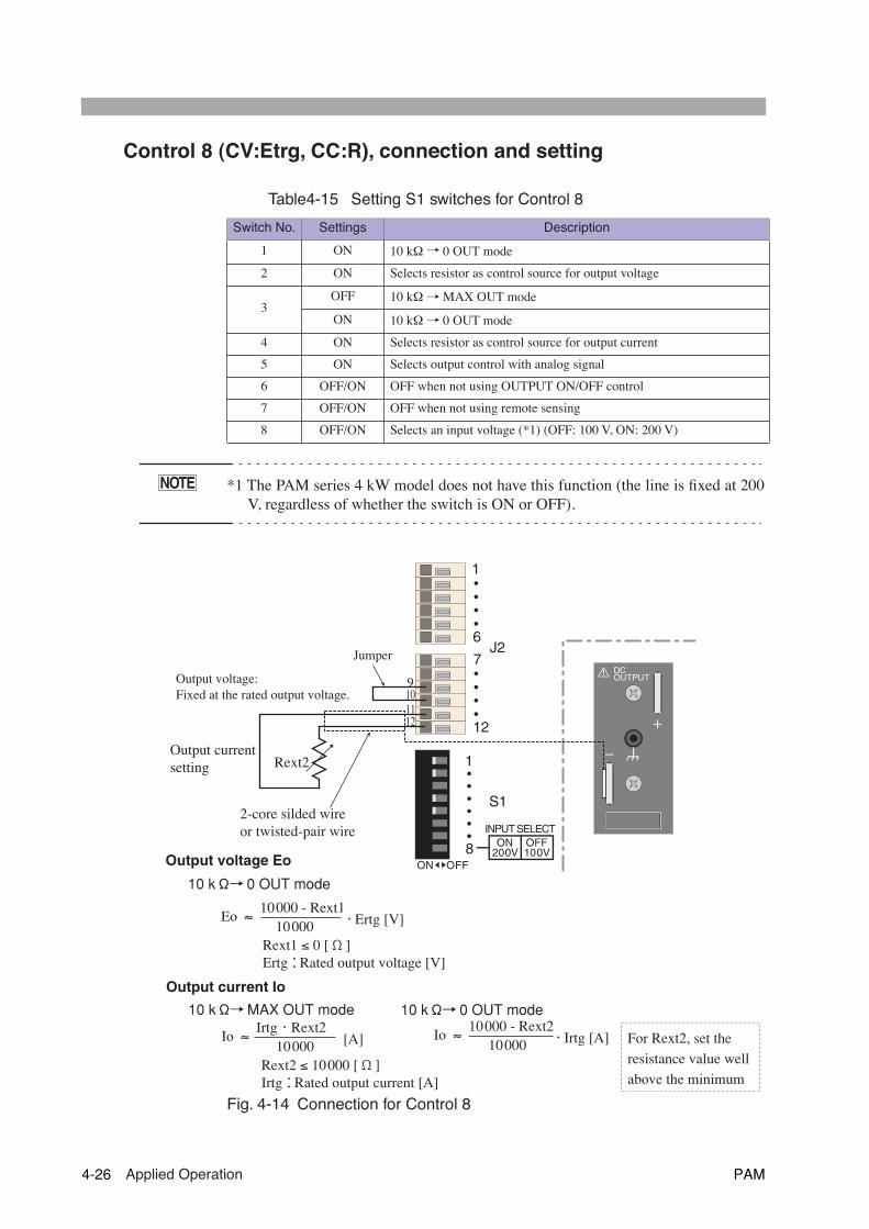
Control 8 (CV:Etrg, CC:R), connection and setting
Table4-15 Setting S1 switches for Control 8
*1 The PAM series 4 kW model does not have this function (the line is fixed at 200V, regardless of whether the switch is ON or OFF).
Fig. 4-14 Connection for Control 8
Switch No. Settings Description
1 ON 10 kΩ→ 0 OUT mode
2 ON Selects resistor as control source for output voltage
3OFF 10 k
Ω→ MAX OUT mode
ON 10 k
Ω→ 0 OUT mode
4 ON Selects resistor as control source for output current
5 ON Selects output control with analog signal
6 OFF/ON OFF when not using OUTPUT ON/OFF control
7 OFF/ON OFF when not using remote sensing
8 OFF/ON Selects an input voltage (*1) (OFF: 100 V, ON: 200 V)
NOTE
6
1
12
7J2
DCOUTPUT
1
8
S1
INPUT SELECT
200V 100VOFF
OFF
ON
ON
2-core silded wireor twisted-pair wire
Output voltage Eo
Rext1 ≤ 0 [Ω]Ertg:Rated output voltage [V]
10 kΩ→0 OUT mode
Eo ≈ 10000 - Rext1 10000 ・Ertg [V]
10 kΩ→MAX OUT mode
Io ≈ Irtg ・ Rext2 10000 [A]
Rext2 ≤ 10000 [Ω]Irtg:Rated output current [A]
10 kΩ→0 OUT mode
Io ≈ 10000 - Rext2 10000 ・Irtg [A]
Output current Io
Rext2
9101112
Output currentsetting
For Rext2, set the resistance value well above the minimum
Output voltage: Fixed at the rated output voltage.
Jumper
4-26 Applied Operation PAM
• Insulate the external resistor source (Rext2), the Jumper and the cableconnected to it with at least the isolation voltage of the unit. For details,see "2.6 Grounding the output terminal"
• When using a shielded cable for the connection, protect the uncoveredpart of the cable with an insulation tube of at least the isolation voltage ofthe unit.
• In the 10 kΩ → MAX OUT mode, if Rext2 is disconnected, an excessivelylarge current can flow or excessively large voltage can output to the load.Connect Rext2 securely to the J2 terminal board.
If there is any danger of Rext2 being cut off and the circuit opened, use the10 k
Ω
→ 0 OUT mode.
• To use a fixed resistor for Rext2 and to control it with a switch, select a
closed short-circuit or continuous switch.
• To reduce the effects of noise on output, use a 2-core shielded wire or a twisted-pair wire to connect between Rext2 and J2 terminal board, making them as shortas possible.Longer wiring results in greater susceptibility to the effects of noise, and use ofcables with antinoise measures may not solve the problem, resulting in improperoperation.When using a shielded wire, connect the shield to the - (neg.) output terminal.
• For Rext2, use a 1/2 W or larger resistor that has a good temperature coefficientand minimal aging effects, such as a metal film resistor or wire-wound resistor.
• Fig. 4-14 shows the general relationship between Rext1 and the output voltage Eoand between Rext2 and output current Io. But since they are approximate formu-las, if you need precise zero and maximum values for output values, adjust the
Rext1 and Rext2 values (Io applied to the 10 k
Ω
→ 0 OUT mode).
WARNING
CAUTION
NOTE
PAM Applied Operation 4-27

When you wish to connect the shield to Vext
• When connecting the shield to the Vext side, do not connect the shield tothe - (neg.) output terminal of the unit.
When using a shielded wire for connection, some external voltage sources mayrequire that the shield be connected to the external voltage source (Vext). In suchcases, the grounding method used for the Vext and the unit creates a condition wherethe output is short-circuited, as shown in Fig. 4-15. Thus, do not connect the shieldto the - (neg.) output terminal of the unit.
Fig. 4-15 A connection where output is short-circuited by the shield
• Do not ground the output of the Vext – float it instead. The potential of ter-minal 5 to terminal 12 of the J2 terminal board are nearly the same as thatof the unit's - (neg.) output terminal, and short-circuit currents are providedto the signal line without a shield.
CAUTION
+
+
–
+
–
–
10
5
2-core shielded wireVext PAM
Output is short-circuited by the shild, causing current to flow.
Ground the + output terminal.
WARNING
4-28 Applied Operation PAM

4.3.2 Output ON/OFF control with an external contact
This method is used to control output ON/OFF operations with an external contact.In this method, you can select either of the following two modes:
Table4-16 Output ON/OFF control mode using an external contact
The OUTPUT switch on the front panel is used to control output ON/OFF using anexternal contact. For outputs, OFF has priority over ON. For this reason, to turn theoutput ON/OFF using an external contact, you need to set the OUTPUT switch onthe front panel to “ON.” See Table 4-17.
Table4-17 Settings for each switch and output status
• To operate without output ON/OFF control using an external contact, set No.6 ofS1 switch to OFF, or you will be unable to turn output ON/OFF with the OUT-PUT switch on the front panel.
Control mode Control mode
Close OFF mode The output is turned OFF when the external contact is closed.
Close ON mode The output is turned ON when the external contact is closed.
Control modeOUTPUT switch on front panel
External contact Output status
Close ON mode(No.6 of S1 switch is ON.)
ONON (Close) ON
OFF (Open) OFF
OFFON (Close)) OFF
OFF (Open) OFF
Close ON mode(No.6 of S1 switch is OFF.)
ONON (Close)) OFF
OFF (Open) ON
OFFON (Close) OFF
OFF (Open) OFF
NOTE
PAM Applied Operation 4-29

Connection and setting for the external contacts
• Never attempt to connect wires to the J2 terminal board while the POWERswitch turned on. This may result in electric shock or damage to the inter-nal circuitry.
• Insulate the external contacts (S) and the cables leading to then with atleast the isolation voltage of the unit. For more information, see "2.6Grounding the output terminal"
• When using a shielded cable for the connection, protect the uncoveredpart of the cable with an insulation tube of at least the isolation voltage ofthe unit.
• When the OUTPUT switch is OFF, the load may suffer a slight reverse current, as areversed polar voltage of about 0.1 V to 0.2 V often occurs at outputs. If a short circuit islikely on the output, be aware that a slight reverse current of a low percentage of the ratedcurrent may occur.The voltmeter and ampere meter display positive values, but not negative voltages orcurrents. Instead, "0 V " or “0 A " is displayed.
1. Turn off the POWER switch.
2. Set the S1 switches as shown in Table 4-18.
3. As shown in Table 4-16, connect a contact S (switch) between terminal5 and terminal 6 of the J2 terminal board.
• To reduce output noise, use a two-core shielded wire or a twisted-pair wire to con-nect the contact to the J2 terminal board. Use as short a wire as possible.The longer the wire, the worse the effects of noise. Even if provided with noiseprotection, such wires can malfunction.When using a shielded-wire, connect the shield to the – (neg.) output terminal.
• The release voltage between terminal 5 and terminal 6 of the J2 terminal board isabout 15 V at maximum, and the short-circuit current is about 5 mA at maximum.
• Use an external contact rated for at least 20 VDC and 10 mA.
• For long-distance wiring, use a small relay and extend the wiring from the coil
side.
4. Turn on the OUTPUT switch.
5. Recheck that the J2 terminal board and setting of switch.
WARNING
NOTE
NOTE
4-30 Applied Operation PAM

Table4-18 Setting S1 switches for output ON/OFF control
*1 The PAM series 4 kW model does not have this function (the line is fixed at 200V, regardless of whether the switch is ON or OFF).
Fig. 4-16 Connection for output ON/OFF control
Switch No. Setting Description
1 OFF/ONNo effect when Switch 5 is OFF.Depends on settings for each control mode when Switch 5 is ON.
2 OFF/ON
3 OFF/ON
4 OFF/ON
5 OFF/ON OFF when not using output control using an analog signal.
6ON Selects the Close ON mode.
OFF Selects the Close OFF mode.
7 OFF/ON OFF when not using remote sensing.
8 OFF/ON Selects an input voltage (*1) (OFF: 100 V, ON:200 V)
NOTE
6
1
12
7J2
DCOUTPUT
1
8
S1
INPUT SELECT
200V 100VOFF
OFF
ON
ON
2-core shilded wireor twisted-pair wire
S
SFor long-distance wiring
Extend this line.
Relay
56
PAM Applied Operation 4-31
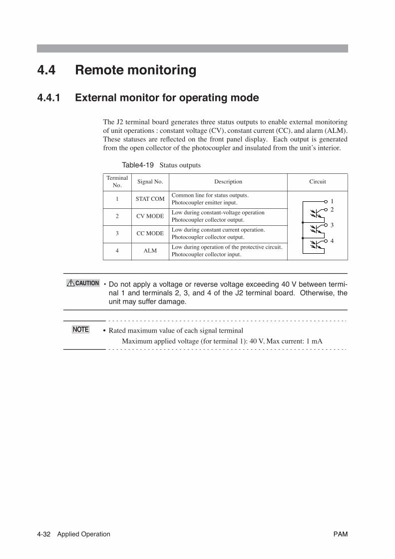
4.4 Remote monitoring
4.4.1 External monitor for operating mode
The J2 terminal board generates three status outputs to enable external monitoringof unit operations : constant voltage (CV), constant current (CC), and alarm (ALM).These statuses are reflected on the front panel display. Each output is generatedfrom the open collector of the photocoupler and insulated from the unit’s interior.
Table4-19 Status outputs
• Do not apply a voltage or reverse voltage exceeding 40 V between termi-nal 1 and terminals 2, 3, and 4 of the J2 terminal board. Otherwise, theunit may suffer damage.
• Rated maximum value of each signal terminal
Maximum applied voltage (for terminal 1): 40 V, Max current: 1 mA
Terminal No.
Signal No. Description Circuit
1 STAT COMCommon line for status outputs.Photocoupler emitter input.
2 CV MODELow during constant-voltage operationPhotocoupler collector output.
3 CC MODELow during constant current operation.Photocoupler collector output.
4 ALMLow during operation of the protective circuit.Photocoupler collector input.
12
3
4
CAUTION
NOTE
4-32 Applied Operation PAM
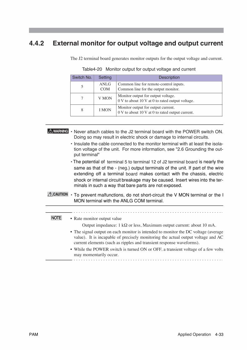
4.4.2 External monitor for output voltage and output current
The J2 terminal board generates monitor outputs for the output voltage and current.
Table4-20 Monitor output for output voltage and current
• Never attach cables to the J2 terminal board with the POWER switch ON.Doing so may result in electric shock or damage to internal circuits.
• Insulate the cable connected to the monitor terminal with at least the isola-tion voltage of the unit. For more information, see "2.6 Grounding the out-put terminal"
• The potential of terminal 5 to terminal 12 of J2 terminal board is nearly thesame as that of the - ( neg.) output terminals of the unit. If part of the wireextending off a terminal board makes contact with the chassis, electricshock or internal circuit breakage may be caused. Insert wires into the ter-minals in such a way that bare parts are not exposed.
• To prevent malfunctions, do not short-circuit the V MON terminal or the IMON terminal with the ANLG COM terminal.
• Rate monitor output value
Output impedance: 1 k
Ω
or less, Maximum output current: about 10 mA.
• The signal output on each monitor is intended to monitor the DC voltage (averagevalue). It is incapable of precisely monitoring the actual output voltage and ACcurrent elements (such as ripples and transient response waveforms).
• While the POWER switch is turned ON or OFF, a transient voltage of a few volts
may momentarily occur.
Switch No. Setting Description
5ANLG COM
Common line for remote-control inputs.Common line for the output monitor.
7 V MONMonitor output for output voltage.0 V to about 10 V at 0 to rated output voltage.
8 I MONMonitor output for output current.0 V to about 10 V at 0 to rated output current.
WARNING
CAUTION
NOTE
PAM Applied Operation 4-33

4-34 Applied Operation PAM
55
Chapter 5 Names and Functionsof Controls
Provides an outline of the switches and terminals on the panels, including theirnames and functions.
Read this chapter to learn the meanings of the alert marks indicated on the pan-els of the unit.
PAM Names and Functions of Controls 5-1

5.1 Front panel
Fig.5-1 Front panel of PAM series 2kW model (PAM80-25)
Fig. 5-2 Front panel of PAM series 4kW model (PAM40-100)
O N
ALARM
OUTPUT
V
A
ON
POWEROFF ON
0--80V 25A
DC OUTPUT
+
REGULATED DC POWER SUPPLY0--80V 25A
PAM80-25POWER
LOCK
1
2
3
MEMORYSET
STORE
CURRENT
VOLTAGE
OVP
COARSE / FINE
OVPMONITOR
ALARMRESET
OUTPUT
ON
OFF
Operation block
[4]
[5]
[1] [2] [3]
O N
ALARM
OUTPUT
V
A
LOCK
1
2
3
MEMORYSET
STORE
CURRENT
VOLTAGE
OVP
COARSE / FINE
OVPMONITOR
ALARMRESET
OUTPUT
ON
OFF
REGULATED DC POWER SUPPLY0--40V 100A
PAM40-100
OFF ON
POWER
Operation block
[4]
[1]
[4]
[5]
5-2 Names and Functions of Controls PAM
[1] POWER
The power switch for the unit. The power is ON when the switch is on the ON side,and OFF when the switch is on the OFF side.
[2] DC OUTPUT (Auxiliary output terminal)
This terminal permits you to obtain outputs from the unit in a simple and quick.Note that this terminal may not meet the unit’s specifications.
• To avoid electric shock, turn the POWER switch OFF before touching thisterminal.
• Models that the rated output current is 50 A or more have no [2] DC OUTPUT(Auxiliary output terminal).
[3] Auxiliary output terminal cover
This terminal cover is used to ensure safety. Before using the unit, install this cover.(Fig. 5-1 shows the unit without the cover.)
• No cover is provided for models without auxiliary output terminals.
[4] Louver
The louver is an air inlet used to exhaust internal heat with a fan. A dust filter isinstalled in the louver. Clean the dust filter periodically. For more information, see"6.1.2 Cleaning the dust filter"
[5] Screw hole
The screw holes on the left and right sides (two holes in the 2 kW model, and fourholes in the 4 kW model) are used for installation of optional rack mount bracketsfor incorporating the unit into a rack.
The following optional rack mount brackets are available.
For PAM series 2kW model
KRB3-TOS (84100) EIA standard (inch type)
KRB150-TOS (84110) JIS standard (metric type)
For PAM series 4kW model
KRB6-PAM (84210) EIA standard (inch type)
KRB300-PAM (84200) JIS standard (metric type)
For details, contact Kikusui distributor/agent.
WARNING
NOTE
NOTE
PAM Names and Functions of Controls 5-3

Operation block
Fig. 5-3 Operation block
[6] OUTPUT
This switch is used to turn outputs ON/OFF. The switch is ON when it is down, andOFF when up. When the line is live, the status is indicated by [20] OUTPUT ON/OFF.
[7] SET
This switch is used to set and check the output voltage and current. To display thepreset output value, turn this switch so that it lights.
[8] LOCK
This switch is used to limit operations on the front panel.
[9] OVP
This variable resistor can be used to make settings for the overvoltage protective cir-cuit. To make settings, keep pressing the [10] OVP MONITOR.
[10] OVP MONITOR
This switch is used to make settings for the overvoltage protective circuit with the[9] OVP.
O N
ALARM
OUTPUT
V
A
LOCK
1
2
3
MEMORYSET
STORE
CURRENT
VOLTAGE
OVP
COARSE / FINE
OVPMONITOR
ALARMRESET
OUTPUT
ON
OFF
Display
[6]
[7]
[8]
[9]
[10]
[11] [12] [13]
[14]
[15]
[16]
5-4 Names and Functions of Controls PAM

[11] ALARM RESET
This switch is used to reset output OFF after the protective circuit is activated.
[12] Dial
Turn this dial in either direction to set the voltage and current.
[13] MEMORY 1/2/3
These switches are used to set the unit to the voltage and current values stored inmemory. When you select and press one to turn it on, the unit is set to a specific setof orders in the memory.
To write values to memory, specify a memory number. See [16] STORE
[14] VOLTAGE
This switch is used in voltage settings to alter the amplitude of change for a singleclick of the dial. Each time the switch is pressed, the setting resolutions (COARSE/FINE) alternate.
[15] CURRENT
This switch is used in current settings to alter the amplitude of change for a singleclick of the dial. Each time the switch is pressed, the setting resolutions (COARSE/FINE) alternate.
[16] STORE
This switch is used to store preset values for output voltage and current in memory.To store the values in the desired memory unit, press this switch, then press one ofthe [13] MEMORY 1/2/3.
PAM Names and Functions of Controls 5-5
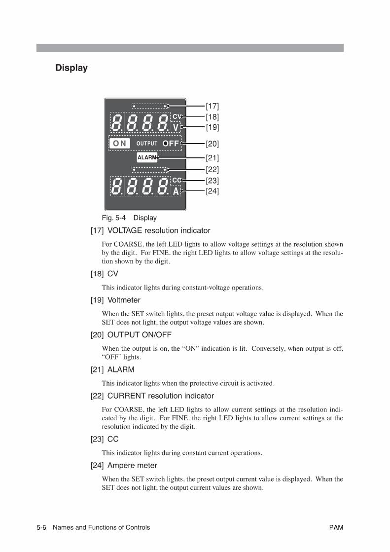
Display
Fig. 5-4 Display
[17] VOLTAGE resolution indicator
For COARSE, the left LED lights to allow voltage settings at the resolution shownby the digit. For FINE, the right LED lights to allow voltage settings at the resolu-tion shown by the digit.
[18] CV
This indicator lights during constant-voltage operations.
[19] Voltmeter
When the SET switch lights, the preset output voltage value is displayed. When theSET does not light, the output voltage values are shown.
[20] OUTPUT ON/OFF
When the output is on, the “ON” indication is lit. Conversely, when output is off,“OFF” lights.
[21] ALARM
This indicator lights when the protective circuit is activated.
[22] CURRENT resolution indicator
For COARSE, the left LED lights to allow current settings at the resolution indi-cated by the digit. For FINE, the right LED lights to allow current settings at theresolution indicated by the digit.
[23] CC
This indicator lights during constant current operations.
[24] Ampere meter
When the SET switch lights, the preset output current value is displayed. When theSET does not light, the output current values are shown.
O N
ALARM
OUTPUT
V
A
[17][18][19]
[20]
[21][22][23][24]
5-6 Names and Functions of Controls PAM
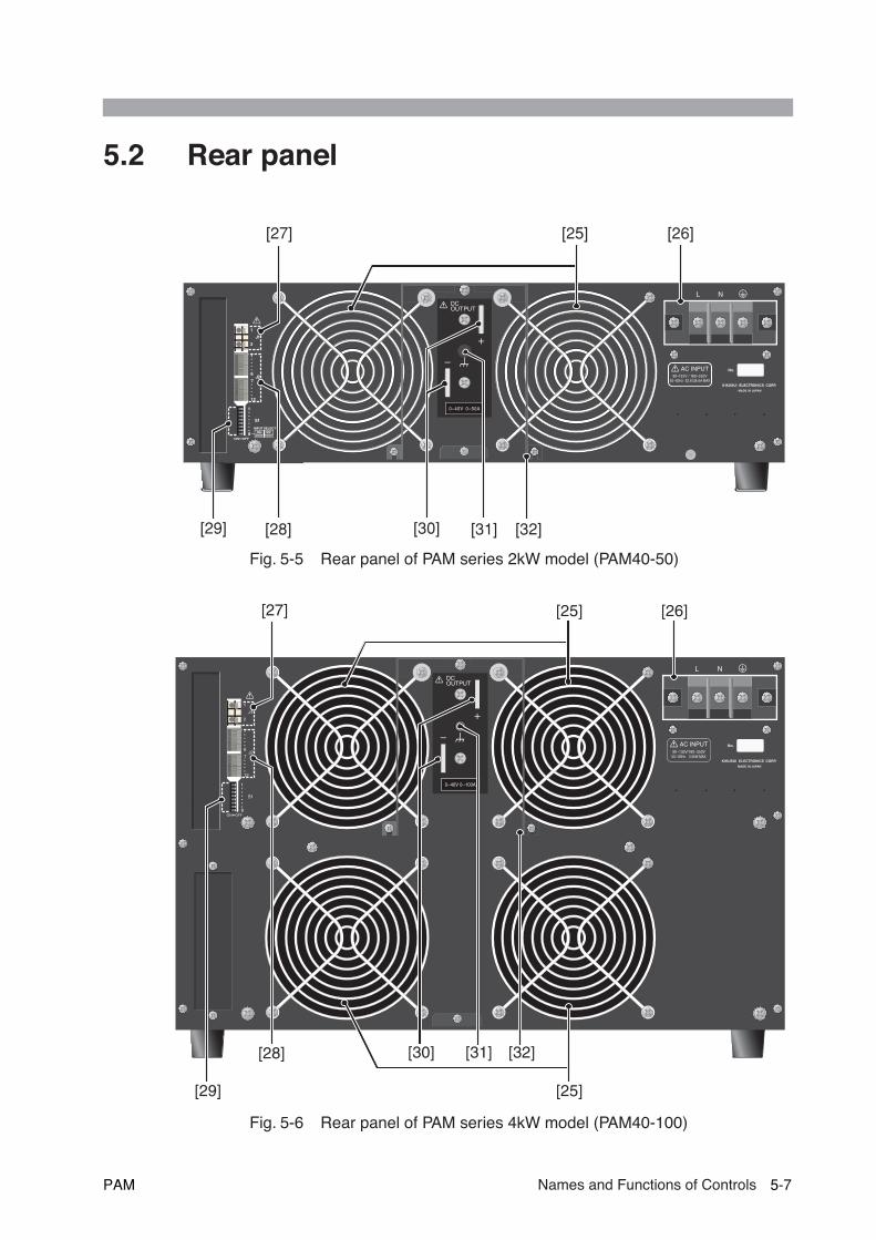
5.2 Rear panel
Fig. 5-5 Rear panel of PAM series 2kW model (PAM40-50)
Fig. 5-6 Rear panel of PAM series 4kW model (PAM40-100)
NL
6
1
1
2
12
7
1
8
J1
J2
S1
INPUT SELECT
200V 100VOFF
OFF
ON
ON
DCOUTPUT
AC INPUT90--132V / 180--250V
50--60Hz 52.8 /28.6A MAX
0--40V 0--50A
[27] [25] [26]
[29] [28] [30] [31] [32]
NL
6
1
1
2
12
7
1
8
J1
J2
S1
OFFON
DCOUTPUT
AC INPUT90--132V/180--250V50 / 60Hz 5.5kW MAX
0--40V 0--100A
[27] [25] [26]
[29]
[28] [30] [31] [32]
[25]
PAM Names and Functions of Controls 5-7

[25] Exhaust ports
This port uses a fan to exhaust heated air from inside. Keep sufficient space aroundthe unit for good ventilation.
[26] AC INPUT
AC input terminals. Connect the supplied AC power cord.
• Incorrect handling may cause electric shock. For details, see "1.5 Con-necting the AC power cord".
• Make sure that the ground terminal is securely grounded. For details, seesection "1.6 Grounding".
[27] J1
This terminal board is used for the remote sensing function.
• Incorrect handling may cause electric shock. For details, see "4.1.1 J1 andJ2 terminal boards".
[28] J2
This terminal board is used for the analog remote control or monitor.
• Incorrect handling may cause electric shock. For details, see "4.1.1 J1 andJ2 terminal boards".
[29] S1
Turn this switch on when using the function. See "4.1.2 S1 switches".
[30] DC OUTPUT
This is the output terminal board.
• To avoid electric shock, always turn off the POWER switch whenever it isnecessary to touch the terminals.
[31]
chassis terminal. See "2.6 Grounding the output terminal".
[32] Output terminal cover
This is the terminal cover for safety. Install the cover on the terminal when the unitis in use.
WARNING
WARNING
WARNING
WARNING
5-8 Names and Functions of Controls PAM

66
Chapter 6 MaintenanceThis chapter describes unit maintenance and calibration, as well as the proper proce-dures for handling unit malfunctions.
PAM Maintenance 6-1
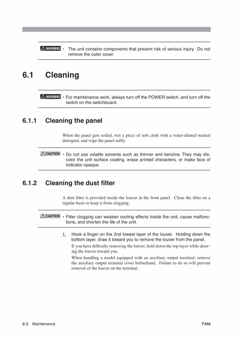
• The unit contains components that present risk of serious injury. Do notremove the outer cover.
6.1 Cleaning
• For maintenance work, always turn off the POWER switch, and turn off theswitch on the switchboard.
6.1.1 Cleaning the panel
When the panel gets soiled, wet a piece of soft cloth with a water-diluted neutraldetergent, and wipe the panel softly
• Do not use volatile solvents such as thinner and benzine. They may dis-color the unit surface coating, erase printed characters, or make face ofindicator opaque.
6.1.2 Cleaning the dust filter
A dust filter is provided inside the louver in the front panel. Clean the filter on aregular basis to keep it from clogging.
• Filter clogging can weaken cooling effects inside the unit, cause malfunc-tions, and shorten the life of the unit.
1. Hook a finger on the 2nd lowest layer of the louver. Holding down thebottom layer, draw it toward you to remove the louver from the panel.
If you have difficulty removing the louver, hold down the top layer while draw-ing the louver toward you.
When handling a model equipped with an auxiliary output terminal, removethe auxiliary output terminal cover beforehand. Failure to do so will preventremoval of the louver on the terminal.
WARNING
WARNING
CAUTION
CAUTION
6-2 Maintenance PAM
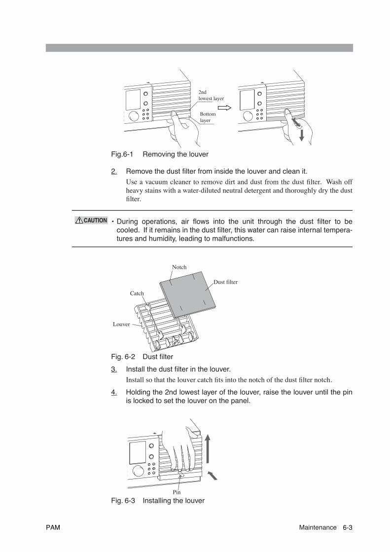
Fig.6-1 Removing the louver
2. Remove the dust filter from inside the louver and clean it.
Use a vacuum cleaner to remove dirt and dust from the dust filter. Wash offheavy stains with a water-diluted neutral detergent and thoroughly dry the dustfilter.
• During operations, air flows into the unit through the dust filter to becooled. If it remains in the dust filter, this water can raise internal tempera-tures and humidity, leading to malfunctions.
Fig. 6-2 Dust filter
3. Install the dust filter in the louver.
Install so that the louver catch fits into the notch of the dust filter notch.
4. Holding the 2nd lowest layer of the louver, raise the louver until the pinis locked to set the louver on the panel.
Fig. 6-3 Installing the louver
Bottom layer
2nd lowest layer
CAUTION
Dust filter
Louver
Catch
Notch
Pin
PAM Maintenance 6-3

6.2 Inspection
AC power cordCheck that there is no damage on the insulation coating, and that the plug is firmlyattached and free from cracks.
• For maintenance work, always turn off the POWER switch and the switchon the switchboard.
• Breaks in the insulation coating may cause electric shock. If a break isfound, immediately stop using the unit.
To purchase accessories, contact Kikusui distributor/agent.
6.3 Calibration
Before shipment, the PAM series is thoroughly calibrated. After a extended periods of use,however, the power supply will require regular calibration.
To have calibration performed, you may contact Kikusui distributor/agent.
WARNING
6-4 Maintenance PAM

6.4 Malfunctions and Causes
This section describes some symptoms of possible malfunctions encountered duringuse of the unit, along with appropriate remedies.
Here, we provide seven typical symptoms and possible check items for each; yousimply find the relevant item. Ideally, you will be able to cure these symptoms with-out difficulty.
When you find a relevant item, follow the corresponding remedy. If this does notsolve or improve the problem, or if no relevant item can be located, please contactKikusui distributor/agent.
Symptom1: The control panel displays nothing.
Symptom2: When you turn on the POWER switch, it is turned off or the "ALARM" LED lights up.
Check item Cause and remedy
□ Check that the wires to the AC IN terminals are connected cor-rectly.
• Wiring to the L, N, and GND terminals is wrong. Connect the wires to these terminals correctly by referring to Sec-tion "1.5 Connecting the AC power cord"
□ Check that the AC power cord contains no broken wires.
• Replace the power code with a new AC power cord.
□ A voltage outside the input volt-age range is input.
• In the PAM series 2kW model, a voltage of 100V is input with the input voltage range set to 200V.To correct the settings, see "1.4 Input power"
Check item Cause and remedy
□ A voltage outside the input volt-age range is input.
• In the PAM series 2kW model, a voltage of 100V is input with the input voltage range set to 200V.To correct the settings, see "1.4 Input power"
PAM Maintenance 6-5
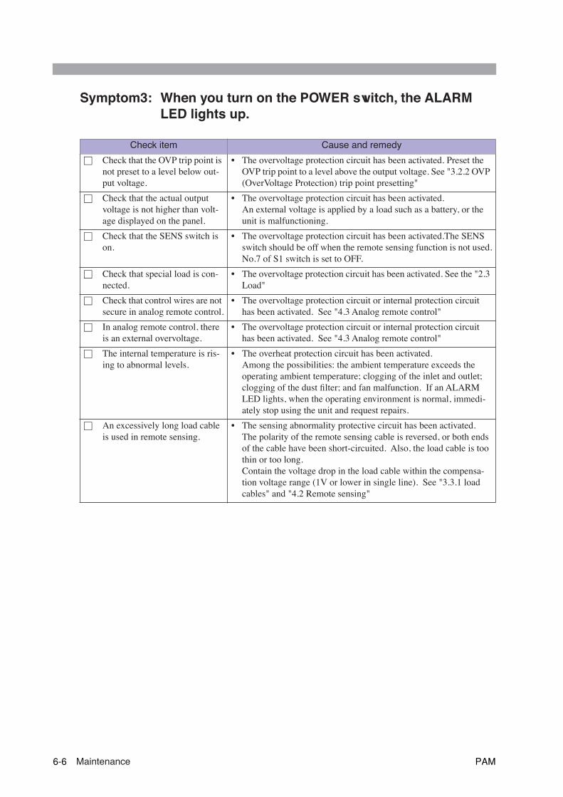
Symptom3: When you turn on the POWER switch, the ALARM LED lights up.
Check item Cause and remedy
□ Check that the OVP trip point is not preset to a level below out-put voltage.
• The overvoltage protection circuit has been activated. Preset the OVP trip point to a level above the output voltage. See "3.2.2 OVP (OverVoltage Protection) trip point presetting"
□ Check that the actual output voltage is not higher than volt-age displayed on the panel.
• The overvoltage protection circuit has been activated. An external voltage is applied by a load such as a battery, or the unit is malfunctioning.
□ Check that the SENS switch is on.
• The overvoltage protection circuit has been activated.The SENS switch should be off when the remote sensing function is not used.No.7 of S1 switch is set to OFF.
□ Check that special load is con-nected.
• The overvoltage protection circuit has been activated. See the "2.3 Load"
□ Check that control wires are not secure in analog remote control.
• The overvoltage protection circuit or internal protection circuit has been activated. See "4.3 Analog remote control"
□ In analog remote control, there is an external overvoltage.
• The overvoltage protection circuit or internal protection circuit has been activated. See "4.3 Analog remote control"
□ The internal temperature is ris-ing to abnormal levels.
• The overheat protection circuit has been activated.Among the possibilities: the ambient temperature exceeds the operating ambient temperature; clogging of the inlet and outlet; clogging of the dust filter; and fan malfunction. If an ALARM LED lights, when the operating environment is normal, immedi-ately stop using the unit and request repairs.
□ An excessively long load cable is used in remote sensing.
• The sensing abnormality protective circuit has been activated.The polarity of the remote sensing cable is reversed, or both ends of the cable have been short-circuited. Also, the load cable is too thin or too long.Contain the voltage drop in the load cable within the compensa-tion voltage range (1V or lower in single line). See "3.3.1 load cables" and "4.2 Remote sensing"
6-6 Maintenance PAM
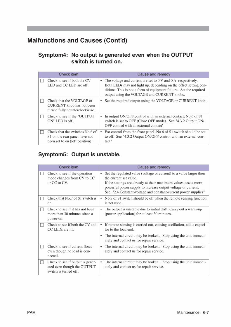
Malfunctions and Causes (Cont’d)
Symptom4: No output is generated even when the OUTPUT switch is turned on.
Symptom5: Output is unstable.
Check item Cause and remedy
□ Check to see if both the CV LED and CC LED are off.
• The voltage and current are set to 0 V and 0 A, respectively.Both LEDs may not light up, depending on the offset setting con-ditions. This is not a form of equipment failure. Set the required output using the VOLTAGE and CURRENT knobs.
□ Check that the VOLTAGE or CURRENT knob has not been turned fully counterclockwise.
• Set the required output using the VOLTAGE or CURRENT knob.
□ Check to see if the "OUTPUT ON" LED is off.
• In output ON/OFF control with an external contact, No.6 of S1 switch is set to OFF (Close OFF mode). See "4.3.2 Output ON/OFF control with an external contact"
□ Check that the switches No.6 of S1 on the rear panel have not been set to on (left position).
• For control from the front panel, No.6 of S1 switch should be set to off. See "4.3.2 Output ON/OFF control with an external con-tact"
Check item Cause and remedy
□ Check to see if the operation mode changes from CV to CC or CC to CV.
• Set the regulated value (voltage or current) to a value larger then the current set value.If the settings are already at their maximum values, use a more powerful power supply to increase output voltage or current.See "2.4 Constant-voltage and constant-current power supplies"
□ Check that No.7 of S1 switch is on.
• No.7 of S1 switch should be off when the remote sensing function is not used.
□ Check to see if it has not been more than 30 minutes since a power-on.
• The output is unstable due to initial drift. Carry out a warm-up (power application) for at least 30 minutes.
□ Check to see if both the CV and CC LEDs are lit.
• If remote sensing is carried out, causing oscillation, add a capaci-tor to the load end.
• The internal circuit may be broken. Stop using the unit immedi-ately and contact us for repair service.
□ Check to see if current flows even though no load is con-nected.
• The internal circuit may be broken. Stop using the unit immedi-ately and contact us for repair service.
□ Check to see if output is gener-ated even though the OUTPUT switch is turned off.
• The internal circuit may be broken. Stop using the unit immedi-ately and contact us for repair service.
PAM Maintenance 6-7
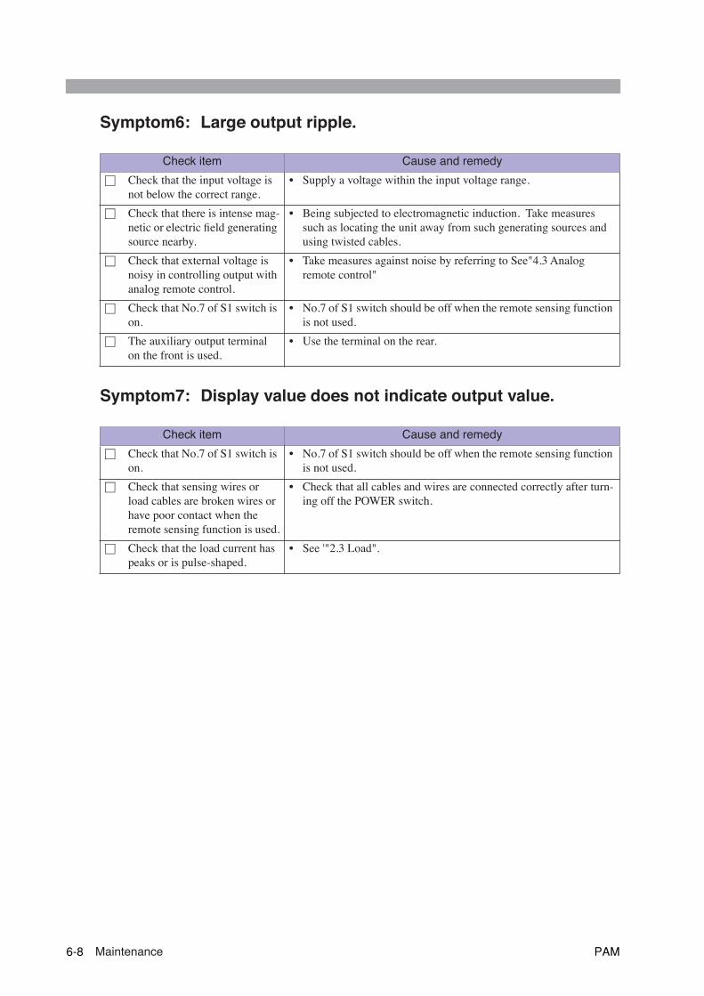
Symptom6: Large output ripple.
Symptom7: Display value does not indicate output value.
Check item Cause and remedy
□ Check that the input voltage is not below the correct range.
• Supply a voltage within the input voltage range.
□ Check that there is intense mag-netic or electric field generating source nearby.
• Being subjected to electromagnetic induction. Take measures such as locating the unit away from such generating sources and using twisted cables.
□ Check that external voltage is noisy in controlling output with analog remote control.
• Take measures against noise by referring to See"4.3 Analog remote control"
□ Check that No.7 of S1 switch is on.
• No.7 of S1 switch should be off when the remote sensing function is not used.
□ The auxiliary output terminal on the front is used.
• Use the terminal on the rear.
Check item Cause and remedy
□ Check that No.7 of S1 switch is on.
• No.7 of S1 switch should be off when the remote sensing function is not used.
□ Check that sensing wires or load cables are broken wires or have poor contact when the remote sensing function is used.
• Check that all cables and wires are connected correctly after turn-ing off the POWER switch.
□ Check that the load current has peaks or is pulse-shaped.
• See '"2.3 Load".
6-8 Maintenance PAM
77
Chapter 7 SpecificationsThis chapter provides the electrical and mechanical specifications for the PAMseries, as well as a list of accessories.
PAM Specifications 7-1
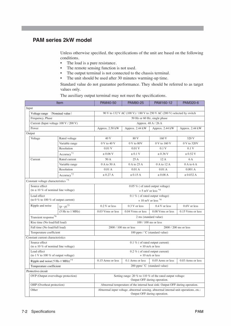
PAM series 2kW model
Unless otherwise specified, the specifications of the unit are based on the followingconditions.• The load is a pure resistance.• The remote sensing function is not used.• The output terminal is not connected to the chassis terminal.• The unit should be used after 30 minutes warming-up time.
Standard value do not guarantee performance. They should be referred to as targetvalues only.
The auxiliary output terminal may not meet the specifications.
Item PAM40-50 PAM80-25 PAM160-12 PAM320-6
Input
Voltage range (Nominal value) 90 V to 132 V AC (100 V) / 180 V to 250 V AC (200 V) selected by switch
Frequency, Phase 50 Hz or 60 Hz, single phase
Current (Input voltage 100 V / 200 V) Approx. 48 A / 26 A
Power Approx. 2.50 kW Approx. 2.44 kW Approx. 2.44 kW Approx. 2.44 kW
Output
Voltage Rated voltage 40 V 80 V 160 V 320 V
Variable range 0 V to 40 V 0 V to 80V 0 V to 160 V 0 V to 320V
Resolution 0.01 V 0.01 V 0.1 V 0.1 V
Accuracy
*1
± 0.06 V ± 0.1 V ± 0.36 V ± 0.52 V
Current Rated current 50 A 25 A 12 A 6 A
Variable range 0 A to 50 A 0 A to 25 A 0 A to 12 A 0 A to 6 A
Resolution 0.01 A 0.01 A 0.01 A 0.001 A
Accuracy
*2
± 0.27 A ± 0.15 A ± 0.08 A ± 0.032 A
Constant voltage characteristics
*3
Source effect(to ± 10 % of nominal line voltage)
0.05 % ( of rated output voltage)
+ 5 mV or less
*4
Load effect(to 0 % to 100 % of output current)
0.1 % ( of rated output voltage)
+ 10 mV or less
*4
Ripple and noise (p - p)
*5
0.2 V or less 0.3 V or less 0.4 V or less 0.6V or less
(5 Hz to 1 MHz) 0.03 Vrms or less 0.04 Vrms or less 0.08 Vrms or less 0.15 Vrms or less
Transient response
*6
2 ms (standard value)
Rise time (No load/full load) 100 / 100 ms or less
Fall time (No load/full load) 2000 / 100 ms or less 2000 / 200 ms or less
Temperature coefficient 100 ppm / ˚C (standard value)
Constant current characteristics
Source effect(to ± 10 % of nominal line voltage)
0.1 % ( of rated output current) + 10 mA or less
Load effect(to 1 V to 100 % of output voltage)
0.2 % ( of rated output current) + 10 mA or less
Ripple and noise( 5 Hz-1 MHz)*7 0.15 Arms or less 0.1 Arms or less 0.05 Arms or less 0.03 Arms or less
Temperature coefficient 200 ppm/ ˚C (standard value)
Protective circuit OVP (Output overvoltage protection) Setting range: 20 % to 110 % of the rated output voltage:
Output OFF during operation.
OHP (Overheat protection) Abnormal temperature of the internal heat sink: Output OFF during operation.
Other Abnormal input voltage, abnormal sensing, abnormal internal unit operations, etc.: Output OFF during operation.
7-2 Specifications PAM

Item PAM40-50 PAM80-25 PAM160-12 PAM320-6
Signal input
External voltage control
(at input of 0 V to approx. 10 V) *8CV: 0 V to rated output voltage, CC: 0 A to rated output current
(CV and CC are controlled separately)
External resistor control 1
(at input of 0 Ω to approx. 10 kΩ) *8CV: 0 V to rated output voltage, CC: 0 A to rated output current
(CV and CC are controlled separately)
External resistor control 2
(at input of about 10 kΩ to 0 Ω) *8CV: 0 V to rated output voltage, CC: 0 A to rated output current
(CV and CC are controlled separately)
Output ON/OFF control With the contact signal (short-circuit), ON or OFF (selected with the switch)
Signal output
Voltage monitor ( 0 V to rated output voltage) 0 V to approx.10 V
Current monitor (0 A to rated output current) 0 V to approx. 10 V
Status CV operating Open collector active Low *9
CC operating Open collector active Low *9
Alarm(With the protective function working)
Open collector active Low *9
Remote sensing Compensating voltage drop: Maximum 1 V, single way. *10
Meter display
Voltmeter (at 23 ˚C ± 5 ˚C) 4 digit indicate, within ±(0.1 % of rdg + 2digits) *11
Ammeter(at 23 ˚C ± 5 ˚C) 4 digit indicate, within ±(0.5 % of rdg + 2digits)*11
Insulation resistance(70 % RH or less of humidity)
Across input and shassis 500 V DC, 30 MΩ or more
Across output and shassis 500 V DC, 20 MΩ or more
Withstanding voltage Across input and output 1500 V AC, 1 min.
Across input and shassis 1500 V AC, 1 min.
Isolation voltage ± 250V ± 500V
Range of operation temperature and humidity 0 ˚C to 50 ˚C, 20 % to 80 % RH (no dew condensation allowed)
Range of storage temperature and humidity -10 ˚C to 60 ˚C, 10 % to 90 % RH (no dew condensation allowed)
Safety Supposed use in IEC61010-1 A2: 1995 Overvoltage Category II.
Cooling system Forced air cooling with fan
Dimensions See outline drawing.
Weight Approx. 18 kg
Accessory Operation manual 1 copy
Power cord 3 pcs.(Clamp terminal on one side 14mm2, 3m)
Chassis connecting cable 1 pc. (Clamp terminal on both sides AWG16, 100 mm) (One fastening screw, M4)
Clamper 1 pair
*1. Rated output voltage, no load,at 23˚C ± 5˚C.*2. Rated output current, short-circuited, at 23˚C ± 5 ˚C.*3. On the rear output terminal.*4. At the sensing point.*5. Measured with an oscilloscope with a frequency of 10 Hz to 20 MHz.*6. Time taken by the output voltage to return to 0.1% ± 10 mV of the preset value when the output current is
changed between 20 % and 100 % at an output voltage range of 50 % to 100 %.*7. Models that output voltage is 80 V or less: within a range from 1 V to 100 %
Models that output voltage is 160 V or more: within a range from 3 % to 100 % *8. One mode is selected with the switch from among the external voltage control, external resistor control 1, and
external resistor control 2 (mode selection is possible separately for CV and CC). CV and CC can be controlledseparately by supplying an external signal.
*9. Maximum applied voltage: 40 V, Maximum current: 1 mA.*10. The output voltage can be compensated for up to the rated output voltage of + 0.6 V (on the rear output termi-
nal).*11. Only positive values are displayed.
PAM Specifications 7-3

PAM series 4kW model
Unless otherwise specified, the specifications of the unit are based on the followingconditions.• The load is a pure resistance.• The remote sensing function is not used.• The output terminal is not connected to the chassis terminal.• The unit should be used after 30 minutes warming-up time.
Standard value do not guarantee performance. They should be referred to as targetvalues only.
The auxiliary output terminal may not meet the specifications.
Item PAM40-100 PAM80-50 PAM160-25 PAM320-12
Input
Voltage range (Nominal value) 180 V to 250 V AC (200 V)
Frequency, Phase 50 Hz or 60 Hz, single phase
Current (Input voltage 200 V) Approx. 48 A
Power Approx. 5.00 kW Approx. 4.88 kW Approx. 4.88 kW Approx. 4.88 kW
Output
Voltage Rated voltage 40 V 80 V 160 V 320 V
Variable range 0 V to 40 V 0 V to 80V 0 V to 160 V 0 V to 320V
Resolution 0.01 V 0.01 V 0.1 V 0.1 V
Accuracy
*1
± 0.06 V ± 0.1 V ± 0.36 V ± 0.52 V
Current Rated current 100 A 50 A 25 A 12 A
Variable range 0 A to 100 A 0 A to 50 A 0 A to 25 A 0 A to 12 A
Resolution 0.1 A 0.01 A 0.01 A 0.01 A
Accuracy
*2
± 0.7 A ± 0.27 A ± 0.15 A ± 0.08 A
Constant voltage characteristics
*3
Source effect(to ± 10 % of nominal line voltage)
0.05 % ( of rated output voltage)
+ 5 mV or less
*4
Load effect(to 0 % to 100 % of output current)
0.1 % ( of rated output voltage)
+ 10 mV or less
*4
Ripple and noise (p - p)
*5
0.3 V or less 0.45 V or less 0.6 V or less 0.9V or less
(5 Hz to 1 MHz) 0.05 Vrms or less 0.06 Vrms or less 0.12 Vrms or less 0.22 Vrms or less
Transient response
*6
2 ms (standard value)
Rise time (No load/full load) 100 / 100 ms or less
Fall time (No load/full load) 2000 / 100 ms or less 2000 / 200 ms or less
Temperature coefficient 100 ppm / ˚C (standard value)
Constant current characteristics
Source effect(to ± 10 % of nominal line voltage)
0.1 % ( of rated output current) + 20 mA or less
Load effect(to 1 V to 100 % of output voltage)
0.2 % ( of rated output current) + 20 mA or less
Ripple and noise( 5 Hz-1 MHz)*7 0.3 Arms or less 0.2 Arms or less 0.1 Arms or less 0.06 Arms or less
Temperature coefficient 200 ppm/ ˚C (standard value)
Protective circuit OVP (Output overvoltage protection) Setting range: 20 % to 110 % of the rated output voltage:
Output OFF during operation.
OHP (Overheat protection) Abnormal temperature of the internal heat sink: Output OFF during operation.
Other Abnormal sensing, abnormal internal unit operations, etc.: Output OFF during operation.
7-4 Specifications PAM

Item PAM40-100 PAM80-50 PAM160-25 PAM320-12
Signal input
External voltage control
(at input of 0 V to approx. 10 V) *8CV: 0 V to rated output voltage, CC: 0 A to rated output current
(CV and CC are controlled separately)
External resistor control 1
(at input of 0 Ω to approx. 10 kΩ) *8CV: 0 V to rated output voltage, CC: 0 A to rated output current
(CV and CC are controlled separately)
External resistor control 2
(at input of about 10 kΩ to 0 Ω) *8CV: 0 V to rated output voltage, CC: 0 A to rated output current
(CV and CC are controlled separately)
Output ON/OFF control With the contact signal (short-circuit), ON or OFF (selected with the switch)
Signal output
Voltage monitor ( 0 V to rated output voltage) 0 V to approx.10 V
Current monitor (0 A to rated output current) 0 V to approx. 10 V
Status CV operating Open collector active Low *9
CC operating Open collector active Low *9
Alarm(With the protective function working)
Open collector active Low *9
Remote sensing Compensating voltage drop: Maximum 1 V, single way. *10
Meter display
Voltmeter (at 23 ˚C ± 5 ˚C) 4 digit indicate, within ±(0.1 % of rdg + 2digits) *11
Ammeter(at 23 ˚C ± 5 ˚C) 4 digit indicate, within ±(0.5 % of rdg + 2digits) *11
Insulation resistance(70 % RH or less of humidity)
Across input and shassis 500 V DC, 30 MΩ or more
Across output and shassis 500 V DC, 20 MΩ or more
Withstanding voltage Across input and output 1500 V AC, 1 min.
Across input and shassis 1500 V AC, 1 min.
Isolation voltage ± 250V ± 500V
Range of operation temperature and humidity 0 ˚C to 50 ˚C, 20 % to 80 % RH (no dew condensation allowed)
Range of storage temperature and humidity -10 ˚C to 60 ˚C, 10 % to 90 % RH (no dew condensation allowed)
Safety Supposed use in IEC61010-1 A2: 1995 Overvoltage Category II.
Cooling system Forced air cooling with fan
Dimensions See outline drawing.
Weight Approx. 30 kg
Accessory Operation manual 1 copy
Power cord 3 pcs.(Clamp terminal on one side 14mm2, 3m)
Chassis connecting cable 1 pc. (Clamp terminal on both sides AWG16, 100 mm) (One fastening screw, M4)
Clamper 1 pair
Weight sticker 1 pc.
*1. Rated output voltage, no load,at 23˚C ± 5˚C.*2. Rated output current, short-circuited, at 23˚C ± 5 ˚C.*3. On the rear output terminal.*4. At the sensing point.*5. Measured with an oscilloscope with a frequency of 10 Hz to 20 MHz.*6. Time taken by the output voltage to return to 0.1% ± 10 mV of the preset value when the output current is
changed between 20 % and 100 % at an output voltage range of 50 % to 100 %.*7. Models that output voltage is 80 V or less: within a range from 1 V to 100 %
Models that output voltage is 160 V or more: within a range from 3 % to 100 %*8. One mode is selected with the switch from among the external voltage control, external resistor control 1, and
external resistor control 2 (mode selection is possible separately for CV and CC). CV and CC can be controlledseparately by supplying an external signal.
*9. Maximum applied voltage: 40 V, Maximum current: 1 mA.*10. The output voltage can be compensated for up to the rated output voltage of + 0.6 V (on the rear output terminal).*11. Only positive values are displayed.
PAM Specifications 7-5

Dimensional drawings
PAM series 2kW model
*12 The PAM40-50 does not have auxiliary output terminal. Unit:mm
PAM series 4kW model
*13 The PAM40-100 and the PAM80-50 do not have auxiliary output terminal. Unit:mm
128MAX150
429.
5
548 MAX20
MAX665
Auxiliary output terminalcover(*12)
548MAX665
MAX20 262
MAX285
429.
5
Auxiliary output terminalcover(*13)
7-6 Specifications PAM

Appendix
About the ROM version
This section explains how to check the version of the ROM used in the unit. Beforemaking inquiries concerning the unit, check the ROM version in accordance withthe following procedure and record the results.
You do not need to check the version if you consider it is inappropriate to turn onthe unit due to an internal fault.
Checking the version
1. While holding down the OVP MONITOR switch, turn the POWER switchON.
2. As shown in Fig. A-1, the display shows four versions for a few sec-onds.
The voltmeter indicates the version type and the ampere meter version number.For versions that include functions not provided in the unit, “- - - -” is dis-played.
3. Following the display of the version numbers, the unit is ready for outputsettings.
Fig.A-1 Versions on display
CC
CV
ALARM
V
A
OFFOUTPUTO N
CC
CV
ALARM
V
A
OFFOUTPUTO N
CC
CV
ALARM
V
A
OFFOUTPUTO N
CC
CV
ALARM
V
A
OFFOUTPUTO N
CC
CV
ALARM
V
A
OFFOUTPUTO N
DAC versionADC version
Power input
Panel version
Waiting for output settingsIF version
A few seconds later
A few seconds later
A few seconds later
A few seconds later
PAM A-1

A-2 PAM
Index
A
AC input terminal 5-8Alarm 2-8ALARM indicator 5-6ALARM RESET switch 5-5Ampere meter 5-6Analog remote control 4-10Auxiliary output terminal 5-3Auxiliary output terminal cover 5-3
C
Calibration 6-4CC indicator 5-6Chassis terminal 5-8Cleaning 6-2COARSE 3-5COARSE/FINE 3-5Connecting load 3-14Connecting to the output terminal 3-16Constant current power supply 3-13Constant voltage power supply 3-12constant-current power supply 2-6CURRENT resolution indicator 5-6CURRENT switch 5-5CV indicator 5-6
D
DC OUTPUT terminal 5-3, 5-8Dial 5-5Dust filter 6-2
E
External monitoring 4-32
F
Factory settings 3-5FINE 3-5
G
Grounding 1-10
I
Input power 1-8Inrush current 2-2Inspection 6-4Installation 1-6Isolation voltage 2-10
J
J1 terminal board 5-8J2 terminalk board 5-8
L
Load cables 3-14LOCK function 3-22LOCK switch 3-22, 5-4Louver 5-3
M
Malfunction 6-5Memory function 3-21MEMORY switch 5-5Monitor output 4-33
N
Negative voltage 2-2
O
Output control with analog signal 4-10Output ON/OFF control with an external contact 4-29OUTPUT ON/OFF switch 5-6OUTPUT switch 5-4Output terminal cover 5-8Overvoltage Protection 3-4OVP MONITOR switch 5-4OVP variable resistor 3-5, 5-4
P
POWER switch 5-3Protective circuits 2-8
PAM I-1

R
Remote monitoring 4-32Remote sensing 4-7ROM version A-1
S
S1 switch 3-2, 4-6, 5-8SET switch 5-4Status outputs 4-32STORE switch 5-5
T
Turning on the power 3-2
V
VOLTAGE resolution indicator 5-6VOLTAGE switch 5-5Voltmeter 5-6
I-2 PAM

PAM
series Regulated D
C pow
er supplyO
PE
RAT
ION
MA
NU
AL