pal-at at30 series operating manual - perma-pipe delete password ..... 26 2.8.3 enter password ........
TRANSCRIPT

Notice
The information contained in this manual, including but not limited to any product specifications, is subject to change without notice.
PERMALERT (PERMALERT), A DIVISION OF PERMA-PIPE, INC., PROVIDES NO WARRANTY WITH REGARD TO THIS MANUAL OR ANY OTHER INFORMATION CONTAINED HEREIN AND HEREBY EXPRESSLY DISCLAIMS ANY WARRANTIES, INCLUDING IMPLIED WARRANTIES, OF MERCHANTABILITY OR FITNESS FOR ANY PARTICULAR PURPOSE WITH REGARD TO ANY OF THE FOREGOING. PERMALERT ASSUMES NO LIABILITY FOR ANY DAMAGES INCURRED DIRECTLY OR INDIRECTLY FROM ANY TECHNICAL OR TYPOGRAPHICAL ERRORS OR OMISSIONS CONTAINED HEREIN OR FOR DISCREPANCIES BETWEEN THE PRODUCT AND THE MANUAL. IN NO EVENT SHALL PERMALERT BE LIABLE FOR ANY INCIDENTAL, CONSEQUENTIAL, SPECIAL, OR EXEMPLARY DAMAGES, WHETHER BASED ON TORT, CONTACT OR OTHERWISE, ARISING OUT OF OR IN CONNECTION WITH THIS MANUAL OR ANY OTHER INFORMATION CONTAINED HEREIN OR THE USE THEREOF.
Caution --This manual may not be up-to-date.
Please check the PermAlert website, www.permalert.com, for the latest revision of this manual.
The manual is typically revised at least once a year. The revision date is on the back cover. Contact [email protected] for technical assistance with the PAL-AT system.

PAL-AT Operating Manual
1
Table of Contents
Safety Information ............................................................................................ 4
1 Introduction ............................................................................................... 5
1.1 Theory of Operation ..........................................................................................................5
1.2 Start Up .............................................................................................................................5 1.2.1 Installation Instructions .........................................................................................5
1.2.2 Initial Display ........................................................................................................6
1.2.2 Time and Date Format .........................................................................................6
1.2.3 LCD Contrast Adjustment ....................................................................................6
1.2.3 Manual Updates ...................................................................................................6
1.2.4 Wiring Diagrams ..................................................................................................6
2 Operating PAL-AT ..................................................................................... 9
2.1 Setup ................................................................................................................................9 2.1.1 Multiple Cable System .........................................................................................9
2.1.2 Exit Setup .............................................................................................................9
2.1.3 Baseline Check ....................................................................................................9
2.1.4 Hydrocarbon Liquids with ZBA ........................................................................... 10
2.1.4.1 Impedance Jumper Setting ............................................................... 10 2.1.5 Sensor String Sections ....................................................................................... 10
2.1.6 Create Setup Table ............................................................................................ 10
2.1.6.1 Select Cable Type ............................................................................. 11
2.1.6.2 Probes .............................................................................................. 11 2.1.6.3 Enter Cable Distance ........................................................................ 11 2.1.6.4 No End Found ................................................................................... 12
2.1.6.5 AT-ORC Functions ............................................................................ 12
2.1.6.6 End of Sensor String ......................................................................... 12 2.1.6.7 Set Sensitivity ................................................................................... 12
2.2 Reference Maps.............................................................................................................. 13 2.2.1 Reference Process............................................................................................. 13
2.2.2 Reference Map Rules ........................................................................................ 13
2.2.3 Reference Issues ............................................................................................... 14
2.3 Verify ............................................................................................................................... 14
2.3.1 Multiple Cable System ....................................................................................... 14
2.3.2 Select the Master Map ....................................................................................... 15
2.3.3 Verify Process .................................................................................................... 15
2.3.4 Select to Monitor ................................................................................................ 16
2.4 Monitor ............................................................................................................................ 16 2.4.1 Normal Messages Displayed ............................................................................. 16
2.4.2 Fault Messages Displayed ................................................................................. 17
2.4.3 Alarm Silence Feature ........................................................................................ 18

PAL-AT Operating Manual
2
2.4.4 Alarm Queue ..................................................................................................... 18
2.4.5 Failure to Enter Monitor Mode ........................................................................... 18
2.5 Display Setup ................................................................................................................. 19 2.5.1 Multiple Cable System ....................................................................................... 19
2.5.2 Display Setup Data............................................................................................ 20
2.5.3 Last Section ...................................................................................................... 20
2.5.4 Add Sections ..................................................................................................... 20
2.5.5 Record the Setup Table .................................................................................... 21
2.6 History of Events ............................................................................................................ 21
2.6.1 History Messages – The First Line .................................................................... 21
2.6.2 History Messages – The Second Line ............................................................... 24
2.7 Set Clock ........................................................................................................................ 24 2.7.1 Set the Time and Date ...................................................................................... 24
2.8 Passwords ..................................................................................................................... 25 2.8.1 Establish New Passwords ................................................................................. 25
2.8.2 Delete Password ............................................................................................... 26
2.8.3 Enter Password ................................................................................................. 26
2.9 Special Functions ........................................................................................................... 26
2.9.1 Set Relay Normal States ................................................................................... 26
2.9.2 Select Language ............................................................................................... 27
2.9.3 Set Special Options ........................................................................................... 27
2.9.3.1 Set Alarm Silence Time .................................................................... 27 2.9.3.2 Set Averaging Rate .......................................................................... 27
2.9.3.3 Set Noise Factor .............................................................................. 28
2.9.3.4 Set AutoSilence................................................................................ 28
2.9.4 Set Baud Rates and Data Format ..................................................................... 28
2.9.5 Set System Identification and Ethernet Addresses ........................................... 29
2.9.6 Enter Phone Number ......................................................................................... 30
2.9.7 Display Cable Data............................................................................................ 30
2.9.7.1 Multiple Cable System ..................................................................... 30
2.9.7.2 Starting Distance .............................................................................. 31 2.9.8 Set Test Mode ................................................................................................... 31
2.10 Communications Options ............................................................................................... 31
2.10.1 PALCOM 10 Software ....................................................................................... 32
2.10.2 Customer Software............................................................................................ 32
2.10.3 Modbus RTU, TCP, and RTU over TCP ............................................................ 34
2.10.3.1 Function Code 3 – Read Registers ..................................................... 34 2.10.3.2 Function Code 16 – Preset Multiple Registers .................................... 34
3 Response to Alarms ................................................................................ 35
3.1 Decisions ....................................................................................................................... 35 3.1.1 Locations ........................................................................................................... 35
3.2 Types of Alarm Conditions ............................................................................................. 35

PAL-AT Operating Manual
3
3.2.1 Fault ................................................................................................................... 35
3.2.2 Break Alarm ....................................................................................................... 35
3.2.3 Short Alarm ........................................................................................................ 35
3.2.4 Drying or Probe Reset Alarm ............................................................................. 35
3.2.5 Leak or Probe Activated Alarm .......................................................................... 35
3.3 Leak Analysis .................................................................................................................. 36 3.3.1 Accessible Applications - Raised Floor systems ................................................ 36
3.3.2 Inaccessible Applications – Contained Piping Systems ..................................... 36
3.3.3 Direct Buried Applications .................................................................................. 36
3.3.4 Repetitive Cycling Alarms .................................................................................. 37
4 Tests and Maintenance ........................................................................... 39
4.1 Select Test Mode ............................................................................................................ 39
4.2 Alarm Test ...................................................................................................................... 39
4.3 Cable Test ...................................................................................................................... 39
4.4 Probe Test ...................................................................................................................... 39
4.5 Battery ............................................................................................................................ 39
4.6 Auxiliary Header.............................................................................................................. 40
4.7 USB Port ......................................................................................................................... 41
4.7.1 Firmware Upgrade ............................................................................................. 41
4.7.2 Data Logger ....................................................................................................... 41
5 Troubleshooting ...................................................................................... 43
5.1 Initial Power-Up Checks .................................................................................................. 43
5.2 System Board ................................................................................................................. 43
5.3 Diagnostic LEDs ............................................................................................................. 43
5.3.1 Port 1 and 2 RS-232/485 ................................................................................... 43
5.3.2 Relays ................................................................................................................ 43
5.3.3 DC Voltages ....................................................................................................... 44
5.3.4 Cable Status ...................................................................................................... 44
5.3.5 24 VDC Reversed Polarity ................................................................................. 44
5.4 Zener Barrier Panel ......................................................................................................... 45 5.4.1 Zener Barrier Assembly Tests ............................................................................ 45
5.4.2 ZBA External Fuse ............................................................................................. 46
5.5 Cable Connector Tests ................................................................................................... 46
5.6 Troubleshooting Guide .................................................................................................... 47
5.7 Restrictions & Limitations ................................................................................................ 48 5.7.1 Sensor Cables ................................................................................................... 48
5.7.2 Probes ................................................................................................................ 49
5.8 PAL-AT Setup Record .................................................................................................... 49
Appendix A - Output Relay System ............................................................... 51

PAL-AT Operating Manual
4
A.1 Installation of Output Relay System ............................................................................... 51
A.2 Relay Module Configuration ........................................................................................... 53
A.3 Internal Diagnostic Indicators ......................................................................................... 54
A.4 Control Relays................................................................................................................ 54
A.5 RS-232 Port Interface Cable Installation ........................................................................ 55
A.6 PAL-AT Control of Output Relay System ....................................................................... 55 A.6.1 Sensing Cable and Probe Requirements .......................................................... 55
A.6.2 Assign Output Relays ........................................................................................ 55
A.6.3 Display Output Relay Assignments ................................................................... 55
A.6.4 Change Output Relay Assignments .................................................................. 56
Warranty .......................................................................................................... 57
Safety Information Please Read This Operating Manual
Please take the time to read this operating manual carefully. It will help you operate your system properly. Failure to follow these instructions may impair the safety of the equipment. Please save this operating manual for future reference.
For your safety
Caution: To reduce the risk of fire or electric shock, do not expose PAL-AT to rain or moisture.
This symbol alerts the user to the presence of uninsulated, dangerous voltage within the system
enclosure that may be of sufficient magnitude to constitute a risk of electric shock.
This symbol alerts the user to the presence of important operating and maintenance instructions in this manual.
Approvals and Certifications
Regulatory Compliance Statements
FCC Class A Notice
This device complies with part 15 of the FCC Rules. Operation is subject to the following two conditions.
1. This device may not cause harmful interference, and 2. This device must accept any interference received, including interference that may cause undesired operation
NOTE: This equipment has been tested and found to comply with the limits for a Class A digital device, pursuant to Part 15 of the FCC Rules. These limits are designed to provide reasonable protection against harmful interference when the equipment is operated in a commercial environment. This equipment generates, uses, and can radiate radio frequency energy and, if not installed and used in accordance with this instruction manual, may cause harmful interference to radio communications.
Operation of this equipment in a residential area is likely to cause harmful interference in which case the user will be required to correct the interference at his own expense.
Changes or modifications not expressly approved by the party responsible for compliance could void the user’s authority to operate the equipment.
The party responsible for product compliance: Perma-Pipe, Inc., 6410 W. Howard St., Niles, IL 60714
CAUTION: TO REDUCE THE RISK OF ELECTRIC SHOCK, TURN OFF POWER BEFORE OPENING ENCLOSURE DOOR.
REFER ALL SERVICING TO QUALIFIED PERSONNEL
PAL-AT Operating Manual
5
1 Introduction
1.1 Theory of Operation PAL-AT® uses a pulsed cable-radar technology to detect leaks. PAL-AT sends out low voltage pulses on a cable and monitors reflections received back at the panel. PAL-AT electronically divides the cable into short increments and measures the reflections from each increment. It stores the measured values in memory during the reference procedure in a permanent record called the “master” map. When in monitor mode, PAL-AT compares the current condition with the master map. Significant changes from the master, for instance when the cable gets wet, cause PAL-AT to enter the alarm mode.
This latest generation of PAL-AT systems automatically creates a new master map after a leak event is detected. This puts the system back on-line immediately to monitor the entire cable for leaks getting larger or new leaks (see section 2.2).
Comparing the current condition with a baseline map enables PAL-AT to monitor a system with minor installation inconsistencies and small amounts of wet cable. PAL-AT can accept initial field conditions that force other systems to reduce their sensitivity or be inoperative. It also enables the system to locate additional leaks occurring past previously detected leaks.
PAL-AT detects and locates six types of changes:
1. Leak
2. Drying
3. Short
4. Break
5. Probe Activated
6. Probe Reset
Normally PAL-AT is set to activate alarms for leaks, shorts, breaks, and probes activated but not for a drying cable or probe reset (see section 2.9.3.2). If the system detects a break or short, it will still monitor for leaks up to the break/short, and display the distance to the leak.
As explained above, PAL-AT accepts and monitors a system with an initial small amount of wet cable. Normally this only occurs in secondary containment applications. To maintain the long-term integrity of the containment and ensure the proper operation of PAL-AT, the containment should be dried before (or shortly after) the system is put on-line. The containment should also be cleaned and dried after any future leak is detected.
1.2 Start Up
1.2.1 Installation Instructions
All applicable manuals must be reviewed and understood prior to installing and operating the PAL-AT system. Detailed installation instructions are provided in the PAL-AT Installation Manual. Refer to that manual for installation for the PAL-AT panel, cables and all accessories.
Caution - Access inside the PAL-AT panel should be limited to qualified personnel. Risk of electrical shock exists.
Power should be fed directly from a dedicated circuit breaker to PAL-AT. If the green power light on the PAL-AT label is not lit, check the circuit breaker and the internal service power switches (see figures 1-1 and 1-2).

1 Introduction
6
PAL-AT LEAK DETECTION SYSTEM, VX.XX
PERMALERT AT30C 13:21:59 2014-07-02
1# MONITOR CABLE, 2# HISTORY OF EVENTS
* TO EXIT, # FOR NEXT MENU
1.2.2 Initial Display
PAL-AT uses a 12-digit keypad for menu selection and data entry. A two-line liquid-crystal display (LCD) shows information about the operation of the system. The initial PAL-AT message is:
LCD1.2-01:
"VX.XX" is the PAL-AT firmware version. The model number, “TIME”, and "DATE" are displayed on the second line. The message is displayed during a 1-minute warm-up period and then PAL-AT attempts to enter monitor mode. The warm-up delay can be bypassed by entering * or #. If * is entered, PAL-AT goes immediately to the Main Menu and displays the message:
LCD1.2-02:
If # is entered, PAL-AT goes directly to Monitor mode if any cables are setup for monitoring.
1.2.2 Time and Date Format
The time and date format follow the recommendations for ISO 8601. The time is displayed using 24-hour format, HH:MM:SS. The date follows the YYYY-MM-DD formant. Due to the limitations of the 2 x 40 character LCD, some “time” displays will omit the “:” and seconds, and the “date” may be displayed as YY-MM-DD or MM-DD. Refer to LCD1.2-01 above for the format.
1.2.3 LCD Contrast Adjustment
Adjust the contrast of the LCD by turning the contrast adjustment screw in the upper left corner of the system board. See figures 1-1 and 1-2. This may be necessary to get the best viewing angle, depending on the mounting height of the PAL-AT panel. A power saver feature dims the LCD backlight if a key is not pressed within 5 minutes and the system is not in alarm.
1.2.3 Manual Updates
PermAlert is a division of Perma-Pipe, Inc. Refer to the PermAlert web site, www.permalert.com, for the latest revision of this manual.
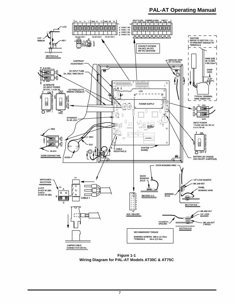
1.2.4 Wiring Diagrams
Figures 1-1 and 1-2 are general wiring diagrams for reference. Refer to the PAL-AT Installation Manual for complete installation and wiring details.
The terminals on the PAL-AT system board use a quick-connect design that provides an easy, fast and robust connection. A flat blade screwdriver, 1/8” [3.5 mm], is used to press down on the terminal lever and open the terminal for easy wire insertion. Release the lever, and the wire is tightly clamped. The acceptable wire size for connection to any terminal, including the mains, is 28 - 12 AWG [0.08-2.5 mm2]. The terminals can accommodate solid or stranded wires. If ferrules are used with stranded wire, the maximum wire size is 14 AWG [1.5 mm2]. Refer to the detail located at the upper right side of figures 1-1 and 1-2. Caution: The lever only travels 1/8” [3.5 mm] to open the terminal completely, and only requires 5 - 8 lbs [2-4 kg] force. Do not exceed these limits or the terminal will be damaged.
PAL-AT Operating Manual
7
Figure 1-1 Wiring Diagram for PAL-AT Models AT30C & AT75C

1 Introduction
8
Figure 1-2 Wiring Diagram for PAL-AT Model AT30K

PAL-AT Operating Manual
9
ENTER CABLE NUMBER [1-4], THEN #:
FOR SETUP * TO EXIT
ALL CALIBRATION AND MAPS WILL BE LOST
* TO EXIT, # TO CONFIRM SETUP DESIRED
STANDARD RESOLUTION, BASELINE = ??
ENTER * FOR MENU, # TO CONTINUE
2 Operating PAL-AT PAL-AT lists the primary functions in the Main Menu. The LCD displays two menu functions at a time. Read the display carefully. PAL-AT prompts for the information it needs. The PAL-AT label has an integral 12-digit keypad to enter 0-9, * and #.
PAL-AT has a password system to prevent unauthorized access. PAL-AT requests a password if the current password is not authorized to enter the selected function. Password access time is very short, ranging from 2 minutes to 60 minutes for selected functions. If the allowable time for the selected function expires without any keypad input, PAL-AT will automatically go to the Monitor function if any cables are on-line.
In the following LCD message examples, question marks (?) represent numbers on the LCD. “TIME” and “DATE” represent a display of a specific time or date.
The Main Menu Functions are:
1. Monitor Cable 2. History of Events
3. Setup Cable 4. Verify Cable
5. Display Setup 6. Set Clock
7. Password Entry 8. Special Functions
The procedure for adding a new cable is to use function 3, Setup. At the completion of Setup, PAL-AT automatically creates a master map and executes the Verify and Monitor functions.
2.1 Setup PAL-AT uses this function to enter cable and probe data into the PAL-AT memory. A level 200 password is required (see section 2.8). While PAL-AT is in the setup function, it is not monitoring any cables previously setup.
To select this function from the Main Menu, enter 3#.
2.1.1 Multiple Cable System
If the system is a model AT30K, the first message is:
LCD2.1-01:
Enter the appropriate cable number.
2.1.2 Exit Setup
The next message is:
LCD2.1-02:
This is an alert that existing data for the selected cable will be erased. If the setup function is entered accidentally, exit this function by entering *. Do not enter # except to setup a new system and erase all previous setup data and reference maps for the selected cable.
2.1.3 Baseline Check
The next message is:
LCD2.1-03:

2 Operating PAL-AT
10
CABLE ? CONNECTED TO ZBA TO MONITOR HC?
ENTER * FOR YES, # FOR NO
The baseline is a number between 25 and 35. If the unit displays a value outside this range, it shows a hardware failure. If so, contact PermAlert for assistance.
2.1.4 Hydrocarbon Liquids with ZBA
Next PAL-AT displays the message:
LCD2.1-04:
Caution: If a cable or probe is monitoring for hydrocarbon liquids (gas, oil, fuel, solvents, etc.) located in a classified or hazardous area, the cable must be connected to a Zener Barrier Assembly (ZBA) in a Zener Barrier Panel (ZBP).
The ZBP and ZBA are also installed for cables in non-hazardous areas to protect the panel from external high voltage spikes. Typically, this is for areas with a high frequency of lightning strikes near the leak detection cables.
2.1.4.1 Impedance Jumper Setting
Before beginning the next step in the Setup process, check the impedance jumper position. Refer to figures 1-1 and 1-2 for positioning the jumper. The 2-pin jumper should be in position A, B, C, or D according to the type of cable and whether the cable is connected to a Zener Barrier Assembly.
Jumper Position Cable Type Zener Barrier Ass’y Installed
A ATP only No B ATP only Yes C All others No D All others Yes
2.1.5 Sensor String Sections
The sensor string is a combination of lengths of jumper cable, sensor cable, and probes connected in series to PAL-AT and monitored for leaks, breaks, etc. During the setup function, the sensor string is broken into several sections. The end of each section is a calibration point. Two general rules determine the required number of sections or calibration points.
The first rule requires a new section or calibration point at every change in cable type. For example, a sensor string consisting of 50 ft [15 m] of jumper cable, 400 ft [120 m] of AGW-Gold cable, and then 20 ft [6 m] of jumper cable is set up as three sections. There may be several cable connectors within one section. The 400 ft of AGW-Gold may consist of 10 lengths of cable, each 40 ft [12 m] long, but they should be connected and entered as one section.
An exception to this rule is if the length of a cable is 15 ft [5 m] or less. For example, one area of a sensor string has 200 ft [60 m] of AGW-Gold, then 15 ft [5 m] of jumper going through a manhole, and finally 200 ft [60 m] of AGW-Gold. The 15 ft jumper cable should be added to the beginning of the second 200 ft of AGW-Gold and these two lengths of cable are setup as one section of AGW-Gold. In this example, the first section is 200 ft, AGW-Gold, and the second is 215 ft, AGW-Gold.
The second rule concerns long lengths of one type of cable. Make additional calibration points at cable connectors approximately every 500 ft [150 m]. Consider a sensor string consisting of 50 ft [15 m] of jumper, 700 ft [215 m] of AGW-Gold, and 20 ft [6 m] of jumper. Instead of setting the cables up in three sections, make an additional calibration point in the 700 ft [215 m] of AGW-Gold to improve the accuracy of the system. In this example, the 700 ft [215 m] of AGW-Gold should be 2 sections, approximately 500 ft [150 m] and 200 ft [65 m] long.
The setup procedure requires the sequential addition of sections to the sensor string and should be planned carefully to assure an accurate calibration.
2.1.6 Create Setup Table
The next message asks for data about each section of the sensor string. PAL-AT uses it to create a setup table. For each cable section, PAL-AT requests: (1) the type of cable and (2) the cumulative distance to the end of the section.

PAL-AT Operating Manual
11
ENTER SECTION ?? CABLE TYPE, THEN #
0=END, 1=ATP, 2=AGW, 3=JMP, # FOR MORE
END FOUND AT ???? INSTEAD OF ????
* TO REENTER, # TO ACCEPT
END FOUND AT ????
* TO REENTER, # TO ACCEPT
ENTER DISTANCE TO SECTION ?? END:
* TO CLEAR, 0 FOR AUTOEND, # TO START
LOCATING END OF SECTION ??, PLEASE WAIT
2.1.6.1 Select Cable Type
There are several types of sensor cables and jumper cables. PAL-AT displays a message requesting the cable type.
LCD2.1-05:
PAL-AT lists several types of cable on each screen. Enter #, if needed, to display additional cable choices. The choices are 0=END, 1=ATP, 3=JMP, JMP-U or JMP-UD, 5=TFH (or TFH-Gold), 9=JPP, 10=Probe, 11=Special, 13=AGW-Gold, and 14=AGT-Gold. Enter the cable type and # to select one.
The first section connected to PAL-AT is always a jumper cable at least 50 ft [15 m] long. It is important to include this jumper cable in the sensor string, even if the first monitored location is less than 50 ft from PAL-AT. If the first section is JPP jumper cable, type 9, it must be at least 65 ft [20 m] long.
There is an exception to this rule for monitoring ATP cable. The first section of cable is also ATP, not jumper cable, and must be at least 50 ft long (see section 10 in the PAL-AT Installation Manual).
2.1.6.2 Probes
Probes are a special case. Probes can be connected to a PAL-AT sensor string anywhere along its length. The maximum number of probes allowed is 10. PermAlert supplies probes with 10 ft [3 m] of jumper cable attached to the input and 50 ft [15 m] to the output of the probe integrator. The probe section length is 60 ft [18 m] for calculating the distance to the end of the section. PAL-AT automatically assigns an identification number (1-10) to each probe.
2.1.6.3 Enter Cable Distance
The next message asks for the distance to the end of the section:
LCD2.1-06:
The distance to the end of the section is the cumulative length of the previously entered sections plus the length of the new section. For example: setting up section 2, which is 500 ft [150 m] of type AGW-Gold cable, where section 1, is 50 ft [15 m] of jumper cable. The distance to the end of section 2 is 550 ft [165 m]. There are two methods to enter the distance: (1) use Autoend or (2) enter the estimated distance. Select Autoend by entering 0#, or just #, and PAL-AT determines the distance to the end of the section automatically. Otherwise, enter the distance and #. In either case, PAL-AT displays:
LCD2.1-07:
If Autoend is selected, the next display is:
LCD2.1-08:
Enter # to accept the distance determined by PAL-AT. If an estimated distance is entered for a section, PALAT finds the end of the section and checks if the measured section length is within tolerance of the estimated distance. If it is, PAL-AT accepts the entry and repeats message LCD2.1-05 for the next section. If the estimated distance is incorrect, then the following message is displayed:
LCD2.1-09:
2 Operating PAL-AT
12
PROBABLE SHORT FOUND IN CABLE ? AT ????
* OR # TO REENTER
NO END FOUND IN CABLE ? IN ???? FEET
* OR # TO REENTER
ENTRY OF ???? IS INVALID - * TO REENTER
MUST BE BEYOND SECTION ?? END AT ????
Enter # to accept or * to reenter the distance determined by PAL-AT. The most likely reason this message is displayed is incorrect information (cable type or length) was entered.
LCD2.1-10:
There are two reasons for displaying message LCD2.1-10. Either the next section was not connected to the cable as intended or the connector on the new section was not installed correctly. Enter * and reenter the data after the problem is corrected.
2.1.6.4 No End Found
If PAL-AT cannot find the end of the cable, one of the following messages is displayed:
LCD2.1-11:
This message shows a short in the cable. Check the cable connectors at the displayed distance. A short in the cable must be repaired before PAL-AT can monitor the sensor string. Refer to section 5.5 for cable connector tests.
OR
LCD2.1-12:
This message is displayed if: (1) the actual end of the section is more than 100 ft [30 m] longer than the estimated distance entered, (2) the end is longer than the maximum length of the system, or (3) the sensor string is disconnected from the panel. Recheck all connectors as described in section 5.5.
2.1.6.5 AT-ORC Functions
If an Output Relay Controller panel (AT-ORC) is connected to PAL-AT, refer to Appendix A for additional information regarding relay assignment in Setup.
2.1.6.6 End of Sensor String
PAL-AT repeats messages LCD2.1-05 through LCD2.1-12 for each new cable segment or probe. The setup table has the capacity for over 50 sensor string sections.
The last section of each sensor string must be jumper cable, except when monitoring ATP cable (see section 10 of the PAL-AT Installation Manual for specific ATP information). A minimum length of 30 ft [9 m] for JMP-U (40 ft [12 m] for JPP) is required. However, a longer section may be required if the previous section is a probe or the sensing string is over 2,500 ft [750 m] long. Refer to section 4 in the PAL-AT Installation Manual.
If the length of the last section of jumper cable is determined by PAL-AT to be shorter than the required lengths listed above, add additional jumper cable to the last section. This happens occasionally when there is mismatch between the impedance of the last sensor cable section and the end jumper cable section. The end jumper cable lengths are used for system calibration and are not monitored for leaks.
After the last cable section data is entered, end the setup table by entering cable type 0 then # at message LCD2.1-05. The end of the last cable section must have a connector attached. Install the red threaded plastic dust cap, supplied with PAL-AT, over the connector.
2.1.6.7 Set Sensitivity
After all the cable sections are setup, the system calculates the recommended sensitivity based on the types of cable selected. The settings are LOW, MED, HI and ADJ. The next message displays the recommended default setting:
PAL-AT Operating Manual
13
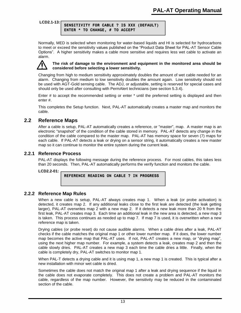
SENSITIVITY FOR CABLE ? IS XXX (DEFAULT)
ENTER * TO CHANGE, # TO ACCEPT
REFERENCE READING ON CABLE ? IN PROGRESS
LCD2.1-13:
Normally, MED is selected when monitoring for water-based liquids and HI is selected for hydrocarbons to meet or exceed the sensitivity values published on the “Product Data Sheet for PAL-AT Sensor Cable Options”. A higher sensitivity makes a cable more sensitive and requires less wet cable to activate an alarm.
The risk of damage to the environment and equipment in the monitored area should be considered before selecting a lower sensitivity.
Changing from high to medium sensitivity approximately doubles the amount of wet cable needed for an alarm. Changing from medium to low sensitivity doubles the amount again. Low sensitivity should not be used with AGT-Gold sensing cable. The ADJ, or adjustable, setting is reserved for special cases and should only be used after consulting with PermAlert technicians (see section 5.3.4).
Enter # to accept the recommended setting or enter * until the preferred setting is displayed and then enter #.
This completes the Setup function. Next, PAL-AT automatically creates a master map and monitors the cable.
2.2 Reference Maps After a cable is setup, PAL-AT automatically creates a reference, or "master", map. A master map is an electronic "snapshot" of the condition of the cable stored in memory. PAL-AT detects any change in the condition of the cable compared to the master map. PAL-AT has memory space for seven (7) maps for each cable. If PAL-AT detects a leak or drying on a sensor string, it automatically creates a new master map so it can continue to monitor the entire system during the current leak.
2.2.1 Reference Process
PAL-AT displays the following message during the reference process. For most cables, this takes less than 20 seconds. Then, PAL-AT automatically performs the verify function and monitors the cable.
LCD2.2-01:
2.2.2 Reference Map Rules
When a new cable is setup, PAL-AT always creates map 1. When a leak (or probe activation) is detected, it creates map 2. If any additional leaks close to the first leak are detected (the leak getting larger), PAL-AT overwrites map 2 with a new map 2. If it detects a new leak more than 20 ft from the first leak, PAL-AT creates map 3. Each time an additional leak in the new area is detected, a new map 3 is taken. This process continues as needed up to map 7. If map 7 is used, it is overwritten when a new reference map is taken.
Drying cables (or probe reset) do not cause audible alarms. When a cable dries after a leak, PAL-AT checks if the cable matches the original map 1 or other lower number map. If it does, the lower number map becomes the active map that PAL-AT uses. If not, PAL-AT creates a new map, or “drying map”, using the next higher map number. For example, a system detects a leak, creates map 2 and then the cable slowly dries. PAL-AT creates a new map 3 each time the cable dries a little. Finally, when the cable is completely dry, PAL-AT switches to monitor map 1.
When PAL-T detects a drying cable and it is using map 1, a new map 1 is created. This is typical after a new installation with minor wet cable is dried.
Sometimes the cable does not match the original map 1 after a leak and drying sequence if the liquid in the cable does not evaporate completely. This does not create a problem and PAL-AT monitors the cable, regardless of the map number. However, the sensitivity may be reduced in the contaminated section of the cable.

2 Operating PAL-AT
14
CHECK CONTINUITY TO END OF CABLE ?
* TO RETURN TO MENU, # CONTINUITY OK
LEAK AT ???? BUT CABLE ? LOOKS ????
SHORTER DUE TO 2ND PROBLEM # TO CONTINUE
DRYING AT ???? BUT CABLE ? LOOKS ????
LONGER DUE TO 2ND PROBLEM # TO CONTINUE
DRYING AT ???? BUT CABLE ? LOOKS ????
SHORTER – POSSIBLE BREAK # TO CONTINUE
2.2.3 Reference Issues
Break, Short or No End Found
If PAL-AT detects a break, short, or no end of the cable, it does not automatically take a new reference map. These problems must be corrected before a new reference map can be taken.
Possible Break Detected
A feature of TDR technology is the electrical pulses sent on the cable travel slower when the cable is wet. They also travel slower in water-based liquids than hydrocarbon liquids. This causes wet cables to look “longer” to PAL-AT compared to dry cables. PAL-AT checks the length of the cable when it takes a reference map after a leak or drying.
PAL-AT stops the reference process in three cases and waits for user input.
When PAL-AT is on-line continuously, it takes a new reference map each time an additional short length of cable dries. If the cable or panel is off-line for an extended time to dry a cable, there can be a significant change in the length of wet cable that can make the cable much “shorter”. It also can be shorter because a length of cable was removed for drying and was not replaced. In either case, when the cable or panel is put on-line, the system detects the drying but the automatic reference process stops and displays the following message:
LCD2.2-02:
If a leak is detected on the cable but the cable appears shorter to PAL-AT, the following message is displayed:
LCD2.2-03:
Similar messages appear if a drying cable appears longer:
LCD2.2-04:
In each of the three cases, enter # for the next message:
LCD2.2-05:
First check the continuity to the end of the cable to make sure all cable is connected (see section 5.5).
The cable with a leak detected may appear shorter due to the cable drying at a previous leak past the current leak. The cable with drying detected may appear longer due to a second leak past the current drying area when the system was off-line.
In either case, if the continuity is correct, continue with reference mapping by entering #.
2.3 Verify Verify is used to turn automatic monitoring on/off for a cable. The verify function also checks if the cable matches any of the reference maps. Select the verify function from the Main Menu by entering 4 and #. A level 200 password is required (see section 2.8).
2.3.1 Multiple Cable System
If the system is an AT30K, the first message is:
PAL-AT Operating Manual
15
ENTER CABLE NUMBER (1-4), THEN #:
FOR VERIFY * TO EXIT
MONITORING USES MAP ?
ENTER # TO USE MAP ? , * FOR ANOTHER
LEAK DETECTED IN CABLE ? AT ???? FEET
ENTER # OR * TO RETURN TO MAIN MENU
CABLE ? MATCHES MAP ? , END AT ???? FEET
MONITOR CABLE ? # FOR YES, * FOR NO
VERIFYING CABLE ?
ENTER MAP TO VERIFY (1-?)
BREAK DETECTED IN CABLE ? AT ???? FEET
BUT SETUP AS ???? FEET. # OR * FOR MENU
LCD2.3-01:
2.3.2 Select the Master Map
PAL-AT prompts to select a map to verify. This is useful to see if the current condition of the cable matches any of the previous maps (see section 3 for further details). The display shows the current master map number. This is the map used during monitoring. The next message is:
LCD2.3-02:
If * is entered, PAL-AT displays:
LCD2.3-03:
Enter the number of the map to compare to the current cable condition, then #.
2.3.3 Verify Process
The next message PAL-AT displays is:
LCD2.3-04:
When the process is completed, PAL-AT displays the following message if the current system matches the selected map:
LCD2.3-05:
This means the cable is in the same condition now as when the map was created. If so, go to section 2.3.4 for the next step.
If the sensor string does not match the selected map, one of several messages is displayed. The first line of the message shows the location and type of problem: leak, drying, short, break, probe activated, probe reset, etc. The second line asks to return to the Main Menu if the map number selected in LCD2.3-03 is not the one being monitored. A few examples are:
LCD2.3-06:
This message is displayed if a leak is detected compared to the selected map.
LCD2.3-07:
If the distance in the first line is shorter than the distance in the second line, there is a break. If the first distance is longer than the second distance, then the end of the cable is now longer than originally setup. This means an additional section of cable is attached to the end of the system. If a sensor string is extended, the additional cable must be added using the Display Setup function (see section 2.5).

2 Operating PAL-AT
16
CABLE ? MATCHES MAP ?, NO END DETECTED
BUT SETUP AS ???? FEET. # OR * FOR MENU
CABLE ? MATCHES MAP ?, END AT ???? FEET
MONITOR CABLE ? # FOR YES * FOR NO
LEAK DETECTED IN CABLE 1 AT ??? FEET
MONITOR CABLE ? # FOR YES, * FOR NO
NO CABLES SET FOR CONTINUOUS MONITORING
ENTER # OR * TO RETURN TO MAIN MENU
CABLE “A” OK
* TO RETURN TO MENU “TIME” “DATE”
MONITORING CABLE “A”, USING MAP “B”
* TO RETURN TO MENU “TIME” “DATE”
LCD2.3-08:
This message is displayed when the cable is disconnected completely from PAL-AT or it is at least 200 ft [60 m] longer than when it was setup.
2.3.4 Select to Monitor
If the map selected in section 2.3.2 matches the cable or is the current one set for monitoring, the second line of the message asks if the cable should be monitored. Example messages are:
LCD2.3-09:
LCD2.3-10:
Enter # to monitor the cable automatically or * to take it off-line and return to the menu. In a multi-cable PAL-AT, a cable may be set off-line when a slow leak or construction in the area of a cable is causing repeated alarms. If a cable is taken on/off-line for monitoring, the action is recorded in the archive history of events (see section 2.6).
2.4 Monitor Enter 1 and # from the Main Menu to put PAL-AT into monitor mode. The display alternates several messages when PAL-AT is in this mode. It shows the number of the cable it is checking and if the cable is OK. The constantly changing display is a self-check by PAL-AT.
When the LCD is not changing, or is blank, it means PAL-AT is not monitoring for leaks. If this occurs, notify appropriate personnel immediately. The green power LED on the door also flashes when PAL-AT is in the main menu and not monitoring.
The system checks each cable for the following conditions: leak, drying, probe active, probe reset, break, short, or cable OK. When a leak or drying is detected, PAL-AT automatically creates a new master reference map and continues to monitor the entire cable. If a break or short is found, the problem must be corrected before the system can monitor the full length of cable and reset the relays.
2.4.1 Normal Messages Displayed
LCD2.4-01:
This message means no cables have been setup or no cables are selected for automatic monitoring. Select cables for automatic monitoring with the Verify function (see section 2.3).
LCD2.4-02:
“A” is the cable number being monitored and “B” is the master map it is compared to.
LCD2.4-03:
This message is displayed when the cable matches the master map.

PAL-AT Operating Manual
17
RECHECKING CABLE “A”, USING MAP “B”
* TO RETURN TO MENU “TIME” “DATE”
FAULT IN FIRST 50 FEET OF CABLE ?
# TO SILENCE ALARM “TIME” “DATE”
LEAK DETECTED IN CABLE ? AT ???? FEET
# TO SILENCE ALARM “TIME” “DATE”
CABLE ? DRYING AT ???? FEET
# TO SILENCE ALARM “TIME” “DATE”
BREAK DETECTED IN CABLE ? AT ???? FEET
# TO SILENCE ALARM “TIME” “DATE”
SHORT DETECTED IN CABLE ? AT ???? FEET
# TO SILENCE ALARM “TIME” “DATE”
PROBE # ?? ACTIVATED IN CABLE ?
# TO SILENCE ALARM “TIME” “DATE”
PROBE # ?? RESET IN CABLE ?
# TO SILENCE ALARM “TIME” “DATE”
NO END FOUND IN CABLE ? IN ???? FEET
# TO SILENCE ALARM “TIME” “DATE”
LCD2.4-04:
PAL-AT displays this message when it first recognizes a fault condition. PAL-AT rechecks the cable three (3) times during the next few seconds before displaying an actual alarm condition and activating the alarm relays.
2.4.2 Fault Messages Displayed
One of the following messages is displayed when a fault is detected:
LCD2.4-05:
OR
LCD2.4-06:
OR
LCD2.4-07:
OR
LCD2.4-08:
OR
LCD2.4-09:
OR
LCD2.4-10:
OR
LCD2.4-11:
OR
LCD2.4-12:
A display above is on for 5 seconds and then alternates with display LCD2.4-04.

2 Operating PAL-AT
18
MONITORING NOT ENABLED
ENTER # OR * TO RETURN TO MENU
* MENU # RESET QUEUE “TIME” “DATE”
THE ALARM QUEUE HAS ?? NEW EVENTS
ENTER * FOR MENU, # TO CONTINUE
CABLE ? HAS ?? NEW EVENTS
ENTER * FOR MENU, # TO CONTINUE
ALL NEW EVENTS ACKNOWLEDGED
ENTER * FOR MENU, # TO VIEW HISTORY
2.4.3 Alarm Silence Feature
When PAL-AT detects a fault condition, it switches two relays – the Common Alarm Relay and a Cable Relay (one for each cable). PAL-AT is shipped with the relays configured to operate in a normally deenergized mode, so they energize in the alarm state (see section 2.9.1 for setting relay configuration).
When any of the messages in 2.4.2 is displayed, enter # to switch the common alarm relay to its normal state and silence the audible alarm. The cable relay remains switched until the fault is cleared or a new reference map is taken and the alarm queue is cleared. The alarm silence feature resets after a preset interval (default is 12 hours) if the fault is not corrected. This reactivates the common alarm relay and audible alarm (see section 2.9.3.1).
2.4.4 Alarm Queue
When PAL-AT detects a leak and automatically creates a new reference map, the alarm queue counter is incremented. After a new map is created, the audible alarm is silenced (AutoSilence) and the common alarm relay is reset, but the cable relay and the red LED on the door are still activated until the alarm queue is reset. Resetting the queue requires a 100 level password to ensure an authorized person acknowledges a leak. The system continues monitoring the cable before and after the queue is reset. Refer to section 2.9.3.4 to disable AutoSilence.
Whenever there are any messages in the queue, the second line of the display is:
LCD2.4-13:
Enter # and the total number of new events is displayed:
LCD2.4-14:
Next, enter # and then a 100 level or higher password. The next message displays the number of events for each cable, 1 thru 4.
LCD2.4-15:
Enter # to display events for the next cable. After the number of events for all cables is shown, the following message is displayed. The cable relay and the red LED on the door return to their normal states. Enter # to go directly to function 2, History of Events, and display the archived events.
LCD2.4-16:
2.4.5 Failure to Enter Monitor Mode
In special cases, PAL-AT may require a master password before it can begin monitoring the first time. The password is unique. Once the password is entered, it is not needed again. Contact PermAlert if the message below is displayed.
LCD2.4-17:
When the master password is issued, select the security function by entering 7# from the Main Menu.

PAL-AT Operating Manual
19
ENTER SECURITY PASSWORD
* TO CLEAR, # TO ACCEPT ENTRY
MONITORING NOT ENABLED
ENTER # TO ENABLE, * TO DISABLE
ENTER CABLE NUMBER (1-4), THEN #:
FOR DISPLAY SETUP * TO EXIT
The display is:
LCD2.4-18:
Enter the master password and #. PAL-AT returns to the Main Menu. Select the monitor function by entering 1#. The message is:
LCD2.4-19:
Enter # and PAL-AT returns to the Main Menu. Enter 1# again and the system begins automatic monitoring.
2.5 Display Setup
Display Setup, function 5, is useful for several purposes.
View Setup Data
Display setup provides an easy method to review the types and lengths of cable sections in the setup (calibration) table. This is useful to make sure they are entered correctly and to see what type of cable is installed at an alarm location. No password is required to view the setup data.
Change Cable Sensitivity
The sensitivity setting for a cable can be changed, without setting up the cable again section by section. To change the sensitivity, enter a 200 level password and then select Display Setup.
Create New Initial Map
Normally map 1 is created at the end of Setup. Sometimes it is preferred to make a new map 1 after several leak/drying cycles. The cables may not match the original master map because of minor residue left in the cable. If the cable is dry, a new map 1 can be created without going through the entire setup process again. Enter a 200 level password and then select Display Setup.
Add Sections to the Cable String
This function also allows adding or changing cable sections at any point in the setup table. This provides for expanding a sensor string in the future without redoing the entire setup procedure.
This is also useful if a system requires more than 1 day to setup. At the end of the first day, end the setup function by entering cable type 0. The system will create a reference map and monitor the cable setup so far. The next day, continue by using display setup as explained below to add the rest of the sections. Enter a 200 level password and then select Display Setup.
Once a section is changed, each section following it must be added to the sensor string, one by one, as before in the Setup function. If a section is changed, all the maps are erased.
AT-ORC Functions
If an Output Relay Controller panel (AT-ORC) is connected to PAL-AT, refer to Appendix A for additional information regarding relay assignment in Display Setup.
2.5.1 Multiple Cable System
If the system is an AT30K, the first message is:
LCD2.5-01:

2 Operating PAL-AT
20
HEREAFTER ENTER # TO SHOW NEXT SECTION
OR * TO EXIT OR REENTER SETUP DATA
HEREAFTER ENTER # TO SHOW NEXT SECTION
ENTER * TO RETURN TO MENU
CABLE ? SO FAR LENGTH=???? COUNT=????
SECT. ?? TYPE=?? LENGTH=???? COUNT=????
CABLE ? END - ENTER * TO ADD A SECTION
ENTER # TO CHECK AUTOMATIC MONITORING
CABLE ? END - ENTER * TO RETURN TO MENU
ENTER # TO CHECK AUTOMATIC MONITORING
CABLE ? SET FOR AUTOMATIC MONITORING
CRI ?? # OR * TO RETURN TO MAIN MENU
CABLE ? NOT SET FOR AUTOMATIC MONITORING
CRI ?? # OR * TO RETURN TO MAIN MENU
2.5.2 Display Setup Data
If a password at level 200 is entered, the next message is:
LCD2.5-02:
Otherwise it is:
LCD2.5-03:
Enter * at any time to exit display setup and return to the Main Menu. Starting at section 1, each time # is entered, PAL-AT displays the setup data for the next section of sensor string. The message is:
LCD2.5-04:
The top line refers to the cumulative total of all the sections, including the selected section. The second line refers to the selected section. "COUNT" refers to an internal counter in PAL-AT. This information is important in case it is necessary to redo the setup table if someone accidentally deletes it (see section 2.5.5).
2.5.3 Last Section
After all the sections are displayed, the next message is:
LCD2.5-05:
OR
LCD2.5-06:
If # is entered, PAL-AT displays either:
LCD2.5-07:
OR
LCD2.5-08:
This shows whether the current cable is set for automatic monitoring.
2.5.4 Add Sections
If * is entered after message LCD2.5-04 and before message LCD2.5-07 and the password is level 200 or higher, then the next message is:

PAL-AT Operating Manual
21
ENTER # TO REENTER SECTION ?? SETUP DATA
ENTER * TO RETURN TO MENU
REST OF SETUP AND ALL MAPS WILL BE LOST
* TO EXIT, # TO CONFIRM REENTRY DESIRED
NO MORE ENTRIES IN HISTORICAL ARCHIVES
ARCHIVES CLEARED IN / “YEAR”
POWER LOST AT “TIME” ON “DATE”, RESTORED
LCD2.5-09:
Enter * to return to the Main Menu. If # is entered, the message is:
LCD2.5-10:
This is a confirmation to continue.
Caution: Do not enter # unless you are prepared to erase the maps and all or part of the setup table. Read section 2.5.5
If # is entered, PAL-AT enters the setup function with the section number displayed. Follow the procedures in Sections 2.1.5 and 2.1.6 to add sensor string sections from that point to the end.
In some instances, e.g. to change the sensitivity, it is desirable to create a new map 1 without setting up the system again. To set a system back to a new map 1, enter * at message LCD2.5-05, # at message LCD2.5-09, and # at message LCD2.5-10. PAL-AT goes into the Setup function to select the next section cable type. Select cable type 0, since it is at the end of the cable, and then select the sensitivity. This ends the setup process without actually adding to the sensor string. The system automatically creates a new master map 1 and monitors the cable.
2.5.5 Record the Setup Table
A listing of the setup table, showing distances and counts for each section, should be recorded. If the setup table is accidentally erased, the listing can be used to reenter the data with a computer or modem without going through the setup process. Contact PermAlert for details. A record form is provided at the end of this manual to keep a permanent record of the setup table.
2.6 History of Events
PAL-AT records a history of the 900+ most recent events. If the history is full and additional events occur, the oldest are deleted (FIFO). The history, or archives, is displayed by selecting menu function 2. All significant events are recorded: alarms, power failures, security password entries, setup, mapping, etc. The records are displayed in sequence from most recent to oldest (LIFO). Enter # to display the next older entry. Enter 9 to change direction and display the next more recent entry. All messages display two lines of information.
2.6.1 History Messages – The First Line
This message is displayed after the last entry.
LCD2.6-01:
This entry is stored when the history was cleared. “YEAR” is a two-digit number from 00-99.
LCD2.6-02:
This entry is stored when a unit is turned on to record when power was previously lost.
LCD2.6-03:

2 Operating PAL-AT
22
SECURITY CODE “A” ENTERED, LEVEL “B”
LEAK DETECTED IN CABLE “A” AT “B” FEET
NEW CABLE “A” REFERENCE, STORED AS MAP“B”
CABLE “A” MONITORING ON, MAP “B” IN/“YEAR”
CABLE “A” DRYING AT “B” FEET
CABLE “A” SETUP, WITH LENGTH OF “B” FEET
CABLE “A” MONITORING OFF IN /“YEAR”
SHORT DETECTED IN CABLE “A” AT “B” FEET
BREAK DETECTED IN CABLE “A” AT “B” FEET
This entry is stored when a sensor string is setup, "A" is the cable number and "B" is the length of the sensor string.
LCD2.6-04:
This entry is stored when a new reference or master map is created. "A" is the cable number and "B" is the map number.
LCD2.6-05:
This entry is stored when a cable is manually put on-line for automatic monitor in the Verify Cable function.
LCD2.6-06:
This entry is stored when a cable is taken off-line.
LCD2.6-07:
This entry is stored when a security code is entered into the unit. "A" is the number of the security code (1-25) and "B" is the security level for the code (1-255). The master password is level 255.
LCD2.6-09:
This entry is stored when a leak is detected. "A" is the cable number and "B" is the distance where the leak is first detected.
LCD2.6-10:
This entry is stored when a cable dries.
LCD2.6-11:
This entry is stored when a short is detected.
LCD2.6-12:
This entry is stored when a break is detected.
LCD2.6-13:

PAL-AT Operating Manual
23
FAULT IN FIRST 50 FEET OF CABLE “A”
NO END FOUND IN CABLE "A" IN "B" FEET
PROBE # “B” RESET IN CABLE “A”
CABLE “A” AUTOSELECT, NOW USING MAP “B”
PROBE # “B” ACTIVATED IN CABLE “A”
ALL NEW EVENTS ACKNOWLEDGED
CABLE “A” AUTOREFERENCE, STORED AS MAP “B”
AUTOMATIC MONITORING ENABLED IN / “YEAR”
AUTOMATIC MONITORING DISABLED IN / “YEAR”
This entry is stored when a cable fault is detected in the first 50 ft [15 m] of the cable.
LCD2.6-14:
This entry is stored when the cable is disconnected from PAL-AT or additional cable is improperly added to the sensor string. "B" is at least 200 ft [60 m] longer than the sensing string setup length.
LCD2.6-15:
This entry is stored when a probe is activated. "B" is the number of the probe.
LCD2.6-16:
This entry is stored when a probe resets to its initial condition, either normally open or normally closed.
LCD2.6-17:
This entry is stored when the alarm queue is cleared.
LCD2.6-18:
This entry is stored when a previous map, "B”, is selected by PAL-AT due to drying cable or a probe reset.
LCD2.6-19:
This entry is stored when a new map "B" is taken by PAL-AT due to drying cable or a probe reset.
LCD2.6-20:
This entry is stored when automatic monitoring is enabled using the "master" password.
LCD2.6-21:
This entry is stored when automatic monitoring is disabled using the "master" password.
LCD2.6-22:

2 Operating PAL-AT
24
YEAR CHANGED FROM “YEAR” TO “YEAR”
AT “TIME” ON “DATE”, # FOR NEXT,*FOR MENU
CURRENT TIME: “TIME” DATE: “DATE”
ENTER HOURS (00-23), THEN #
ENTER MONTH (01-12), THEN #
ENTER DATE (01-31), THEN #
ENTER YEAR (00-99), THEN #
TIME RESET TO “TIME”, DATE TO “DATE”
ENTER MINUTES (00-59), THEN #
This entry is stored when the clock is reset, "TIME" and "DATE" are the new time and date.
LCD2.6-23:
This entry is stored when the year is changed using “Set Clock”, or automatically on January 1 of any year. The year is displayed with four digits.
LCD2.6-24:
2.6.2 History Messages – The Second Line
The second line of the history message always displays the time and date when an event occurred:
LCD2.6-25:
2.7 Set Clock PAL-AT has an internal clock and calendar. The current time and date are displayed when the unit is in monitor mode. PAL-AT has a battery to keep the clock running, when power is off, for up to one year. If the battery fails, PAL-AT automatically sets the date to 1/1/2012 when power is restored (see section 4.4).
2.7.1 Set the Time and Date
Enter 6# from the Main Menu to select this function. Security password level 50 is required for this function. The first line of the message is:
LCD2.7-01:
The second line steps through several displays. Enter * to reenter a number or exit the Set Clock function. The second line displays are:
LCD2.7-02:
LCD2.7-03:
LCD2.7-04:
LCD2.7-05:
LCD2.7-06:
Note: PAL-AT uses the 24-hour time display.

PAL-AT Operating Manual
25
ENTER SECURITY PASSWORD
* TO CLEAR, # TO ACCEPT ENTRY
ENTER PASSWORD TO ADD/DELETE
MUST BE 6 TO 10 CHARACTERS LONG
NOT FOUND - ENTRY ?? AVAILABLE
# TO ADD, * TO RETURN TO MENU
ENTER SECURITY LEVEL (1-250)
2.8 Passwords PAL-AT has several security levels. The following table lists the menu functions and required security levels:
Security Level Required
Menu Function Level
1 – Monitor None 5 - Display setup (read only) 2 – History Silence Alarm
6 - Set Clock 50
4 – Verify 100 Clear alarm queue
3 - Setup Cable 200 5 - Display Setup (add sections)
7 - Security (add security passwords) 250 8 - Special Functions
PAL-AT asks for a password if a function is selected that requires a higher security level than the most recent password. After a password is entered, PAL-AT continues with the selected menu function.
2.8.1 Establish New Passwords
PAL-AT initially uses a default password, 7089662190, with a security level of 250. Use this password to set up additional passwords at any security level from 50 to 250. PAL-AT allows 25 different user passwords. After you establish another password at level 250, delete the default password to prevent unauthorized access to PAL-AT.
To set up new passwords, select the security function by entering 7# from the Main Menu. The message is:
LCD2.8-01:
Enter a level 250 password and #. Then enter 7# again. The message is:
LCD2.8-02:
Enter 6 to 10 digits and #. After # is entered, either message LCD2.8-03 or LCD2.8-05 is displayed:
LCD2.8-03:
If the password is not assigned, this is displayed, showing the number of the next space available in the table of 25 passwords. Enter # and the message is:
LCD2.8-04:
Enter the security level corresponding to the Main Menu functions this password can access and then enter #. To add another new password, enter 7# again and repeat LCD2.8-02 to LCD2.8-04.

2 Operating PAL-AT
26
FOUND AS ENTRY ??, WITH LEVEL ???
# TO DELETE, * TO RETURN TO MENU
ENTER SECURITY PASSWORD XXXXXX
* TO CLEAR, # TO ACCEPT ENTRY
1# SET RELAY NORMAL STATES
* = MAIN MENU, # = NEXT SPECIAL MENU
COMMON RELAY (ALARM) IS NORMALLY OPEN
SET NORMAL STATE: * = CLOSED, # = OPEN
2.8.2 Delete Password
Follow the steps for messages LCD2.8-01 and LCD2.8-02. If the password entered in LCD2.8-02 is assigned, the message is:
LCD2.8-05:
Delete this password by entering #. This procedure is also used to change the security level of a password. First, delete the password and then reenter it with the new security level as discussed above. If only # is entered at message LCD2.8-02 then PAL-AT returns to the Main Menu and ends the password editing session.
2.8.3 Enter Password
Select a password by entering 7# from the Main Menu. Enter the password digits. The display shows X’s instead of the actual numbers as they are entered. Enter # to end and return to the Main Menu. Next, select a function from the Main Menu.
LCD2.8-06:
2.9 Special Functions
Several special system functions are available in a separate menu.
(1) Set Relay Normal States
(2) Select Language
(3) Set Special Options - Alarm silence - Averaging Rate – Noise Factor
(4) Set Baud Rates, Data Type
(5) Set System Identification, Ethernet addresses
(6) Enter Phone Numbers (also see “PALCOM 10 User’s Guide”)
(7) Display Cable Data
(8) Set Test Mode
From the Main Menu, enter 8# to select the Special Function Menu. A level 250 password is required. The first message is:
LCD2.9-01:
2.9.1 Set Relay Normal States
The Fault relay is energized whenever the panel is powered. It can be used to monitor for power loss.
The PAL-AT Common Alarm relay and Cable relays can be configured normally open (de-energized) or normally closed (energized). An alarm switches the relays to the opposite state. The labels on the relay terminal strips refer to the form C contacts in their open or de-energized state (see figures 1-1 and 1-2).
To change the relay operation from the default normally open (de-energized) configuration, enter 1# from the Special Function Menu. The message is:
LCD2.9-02:

PAL-AT Operating Manual
27
CABLE RELAY IS NORMALLY OPEN
SET NORMAL STATE: * = CLOSED, # = OPEN
ACTIVATE CABLE RELAY ON LEAK ONLY?
ENTER * FOR YES, # FOR NO
SET ALARM SILENCE TIME
ENTER HOURS (MAX. 96), THEN #
SET ALARM SILENCE TIME
?? HOURS. ENTER MINUTES, THEN #
SELECTED LANGUAGE NOW: ENGLISH - ft
ENTER * TO CHANGE, # TO ACCEPT
Enter * or # to select the desired state of the Common Alarm relay, the relay controlled by the silence feature. The next message is:
LCD2.9-03:
Enter * or # to select the desired state of the cable alarm relay(s).
The Cable relay(s) can be set to activate in response to a "Leak" and not other faults, such as, "Break", "Short", "No End Found", etc. The Common Alarm relay activates in response to all alarms. The next message is:
LCD2.9-04:
The factory default is no, which sets the Cable relay to activate for all cable problems. Select a setting.
The relays are permanently set to alarm if the system is not in monitor mode. If automatic monitoring is disabled for all cables, the relays will activate.
2.9.2 Select Language
The default language is English using feet as the unit of measure. There are several choices available including English (metric), German (metric) and Spanish (metric). Enter * to change the selection. Enter # when the correct language is displayed.
LCD2.9-05:
2.9.3 Set Special Options
There are three options to set with this function: (1) the length of time of the alarm silence, (2) averaging rate and (3) noise factor. PAL-AT goes through these options in sequence.
2.9.3.1 Set Alarm Silence Time
PAL-AT is normally shipped with the alarm silence interval set for 12 hours as described in section 2.4.3. The interval can be set from 1 minute to 96 hours to suit specific applications. To change the alarm silence time enter 3# from the Special Function Menu. The message is:
LCD2.9-06:
Enter the number of hours from 0 to 96 and #. The next message is:
LCD2.9-07:
Enter the number of minutes from 0 to 59 and #. A silence time of 0 hours and 0 minutes defaults to 12 hours.
2.9.3.2 Set Averaging Rate
PAL-AT has provisions for increasing the number of pulses applied to the cable to cancel the effect of interference in “noisy” areas. However, the higher number slows the system and it requires approximately 15 seconds to monitor 5,000 ft [1500 m] of cable.
This is rarely required, but contact PermAlert for more information to use the special sampling rate. To change the sampling rate, enter 5# for 50 Hz or 6# for 60 Hz interference at the following message.

2 Operating PAL-AT
28
PORT 1 BAUD RATE NOW ????
ENTER * TO CHANGE, # TO ACCEPT
SET SAMPLE AVERAGING, THEN #
0 = NORMAL, 5 = 50 CYCLE, 6 = 60 CYCLE
ENTER NOISE FACTOR (4-63): 63
* TO CLEAR, # TO ACCEPT ENTRY
PORT 2 BAUD RATE NOW ????
ENTER * TO CHANGE, # TO ACCEPT
DATA FORMAT FOR PORT 1: ASCII (PALCOM)
ENTER * TO CHANGE, # TO ACCEPT
DATA FORMAT FOR PORT 2: MODBUS
ENTER * TO CHANGE, # TO ACCEPT
SET AUTOSILENCE STATUS FOR LEAKS/PROBES
ENTER # TO ENABLE, * TO DISABLE
Enter 0#, or #, for the default normal sampling.
LCD2.9-08:
2.9.3.3 Set Noise Factor
The default setting for this is 63. It is normally used for diagnostic purposes. Do not change it unless directed by a PermAlert technician. Enter # to accept the default entry.
LCD2.9-09:
2.9.3.4 Set AutoSilence
AutoSilence is a function of PAL-AT that silences the alarm when a new reference map is automatically created following a leak or probe activation. The default setting is enabled. If it is disabled, pressing the # key will silence the audible alarm and common alarm relay and they will reactivate following the configured alarm silence period. Alarms for breaks and shorts are not affected by this setting and they will activate.
LCD2.9-10:
2.9.4 Set Baud Rates and Data Format
The baud rate for serial ports 1 and 2 can be set from 1200 to 115,200 baud. The default is 38,400. To set the baud rates enter 4# from the Special Functions Menu.
The first message, for port 1, is:
LCD2.9-11:
Enter # to accept the displayed rate (????) or enter * until the proper rate is displayed.
In a similar manner, set the baud rate for port 2.
LCD2.9-12:
The data format for each port is selected next. The choices are ASCII, for PALCOM or customer communication program, and Modbus, for Modbus RTU.
LCD2.9-13:
Enter # to accept the displayed format or enter * until the proper format is displayed.
In a similar manner, set the format for port 2.
LCD2.9-14:

PAL-AT Operating Manual
29
ENTER SYSTEM ID (1-254): ???
* TO CLEAR, # TO ACCEPT ENTRY
NEXT, ENTER ETHERNET ADDRESSES
ENTER * FOR MENU, # TO CONTINUE
ENTER IP ADDRESS: 010.001.005.154
* TO CLEAR, # TO ACCEPT ENTRY
ENTER SUBNET MASK: 255.255.255.000
* TO CLEAR, # TO ACCEPT ENTRY
ENTER GATEWAY: 010.001.200.020
* TO CLEAR, # TO ACCEPT ENTRY
MAC ADDRESS: 10-5C-3B-A1-1A-76
SN: 321311801 * OR # TO RETURN TO MENU
MAC ADDRESS NOT SET.
ENTER * FOR MENU, # TO CONTINUE
ENTER SYSTEM SERIAL NO.: 321311801
* TO CANCEL # TO ACCEPT ENTRY
2.9.5 Set System Identification and Ethernet Addresses
Each PAL-AT must have a unique identification number, or address, from 1 to 254. Enter 5# from the Special Function Menu to set the identification number.
The display is:
LCD2.9-15:
Enter a number from 1 to 254 (usually in sequence 1, 2, 3...) for the system and then enter #.
If the PAL-AT is connected to a network via the Ethernet RJ-45 jack on the system board, then the required network information must be added. If the Ethernet is not used, enter * to exit.
LCD2.9-16:
First, the IP address is displayed. The default address is 255.255.255.255. Enter * to clear the display and reenter the correct address. Each field must have 3 digits. The numbers in the following messages are examples.
LCD2.9-17:
Similarly, set the subnet mask:
LCD2.9-18:
In addition, set the gateway:
LCD2.9-19:
If the MAC address has been entered, it will be displayed next with the system serial number. If not, LCD2.9-21 will be displayed.
LCD2.9-20:
LCD2.9-21:
If the PAL-AT system is upgraded from earlier firmware that did not have the MAC address entered at the factory, the address will be created by the system. Enter # if message LCD2.9-21 is displayed. The next message prompts for the serial number on the system board. Enter the 9-digit serial number, omitting any suffix letters. Make sure the serial number is entered correctly. If you have any questions, contact PermAlert Tech Support for assistance.
LCD2.9-22:

2 Operating PAL-AT
30
ENTER CABLE NUMBER (1-4), THEN #:
FOR CABLE DATA * TO RETURN TO MENU
MAC ADDRESS: 10-5C-3B-A1-1A-76
SN: 321311801 * OR # TO RETURN TO MENU
After the serial number is accepted, the MAC address and serial number are displayed.
LCD2.9-23:
2.9.6 Enter Phone Number
Refer to the "PALCOM 10 User’s Guide" for details of this function.
2.9.7 Display Cable Data
PAL-AT has a feature to display the current cable data that is compared to the "map" during monitoring. This is a diagnostic tool if PALCOM software is not available, especially during initial start-up. If you suspect the cable may be wet during the initial setup because PAL-AT determines the system length is much longer than expected, you can view the data. A graph of the data for a typical system with a single wet area of cable looks like figure 2-1.
Figure 2-1
A normal dry cable has values between 25 and 35. The dry section of cable data may be a straight horizontal baseline or vary ± 3 to 4 points vertically as shown. The start of a typical wet area has values drop toward 0 as shown at 50 ft. Following the leak area there is a rise in the values, as shown at 120 ft. This is a typical leak signature. The beginning of the rise to a value of 63 at 210 ft. is a typical end of cable (or break) signature.
There is wide variation in the values depending on how much cable is wet, length of cable, the types of cable used, if probes are installed, etc. For example, a larger leak may go down to 0 at 50 ft, rise to 63 at 120 ft. drop back down to 32 and finally rise to 63 at the end. The important point is the leak typically starts where the values start dropping quickly to 20 or less. Contact PermAlert for additional information on data analysis. Enter 7# from the Special Function Menu to select the Display Cable Data function.
2.9.7.1 Multiple Cable System
If the system is an AT30K, the first message is:
LCD2.9-24:
Enter the cable number and #. PAL-AT automatically verifies the selected cable to get the current data.

PAL-AT Operating Manual
31
CABLE ?, ENTER STARTING DISTANCE, THEN #
* TO RETURN TO MENU
196 201 206 211 216 221 226 231 236
31 31 31 31 33 51 63 63 63
MAPPING MODE-NORMAL. SELECT MODE
* DISABLE MAPPING, # ENABLE MAPPING
MAPPING MODE-DISABLED FOR TESTS. SELECT
* DISABLE MAPPING, # ENABLE MAPPING
PAL-AT LEAK DETECTION *TEST MODE* VX.XX
PERMALERT AT30C “TIME” “DATE”
2.9.7.2 Starting Distance
Enter the starting distance and #. This distance can be at the beginning of the sensor cable or anywhere along the cable, corresponding to the distance axis in figure 2-1 above.
LCD2.9-25:
The following display shows typical data for a cable 211 ft long, similar to the example above. The top row displays distance, in feet or meters, or the X-axis. The second line has a value for each location, as shown in the Y-axis above. Enter # to display the next set of data or enter 9 to display the preceding length of cable. Enter * at any time to enter a new starting distance or return to the Special Function Menu.
LCD2.9-26:
2.9.8 Set Test Mode
Test mode does not allow PAL-AT to create new reference maps in response to leaks or drying. It is very useful for testing.
A good example is during commissioning of a new system when several leaks are created to verify the function of the system. The first leak should be created at the farthest test point from the panel. The PAL-AT displays the alarm location of the leak. As additional leaks are created closer to the panel, the display changes and shows the closest wet area. After the cable dries at the end of the testing, and the panel shows “Cable OK”, test mode should be disabled.
To change the Test Mode, enter 8# from the Special Function Menu. One of the following two messages is displayed. Enter * or # as appropriate.
LCD2.9-27:
LCD2.9-28:
If mapping is disabled for Test Mode, the initial power up message is changed:
LCD2.9-29:
2.10 Communications Options PAL-AT can communicate via several protocols. Simple ASCII commands are used by PALCOM or a customer developed driver. Modbus TCP and Modbus RTU data are available to send to a Modbus client.
The data can be passed via the RS-232 or RS-485 lines or via the Ethernet. If data is sent via RS-232 or RS-485, the data format must be designated for the specific serial port (see section 2.9.4). If data is sent via the Ethernet, the following Ethernet ports are used:
ASCII data -> port 1024 Modbus TCP -> port 502 Modbus RTU over TCP -> port 1050

2 Operating PAL-AT
32
2.10.1 PALCOM 10 Software
PermAlert offers Windows®-based PALCOM 10 Communication software packages that monitor up to 254 PAL-AT systems 24/7. Refer to the “Communications Options for PAL-AT and LiquidWatch” data sheet or the Palcom 10 User’s Guide for details.
2.10.2 Customer Software
In addition, PAL-AT can communicate with an external computer using software written by the customer to read the display and enter keypad data. The communications protocol uses ASCII characters.
The data format is:
8 data bits 1 stop bit No parity 9600 to 115,200 baud
AD Command
First, an address command must be sent to the system. The address command is "AD,XX" where "XX" is the address, or System ID, of the system in hexadecimal format. Allowable values are 01 to FE (1 to 254). The “ESCape” key character clears the PAL-AT input buffer. It is recommended to send “ESC” before the address string at the beginning of each communication session. The corresponding system responds with a prompt "MON 30A> " (30 may vary).
DI Command
The “DI”, or Display, command enables the user to read the PAL-AT LCD display remotely. When PALAT receives the ASCII string "DI", it transmits 2-lines, 40 characters each, plus CR, that duplicates the LCD display.
KP Command
The “KP”, or Keypad, command allows the user to enter keypad data remotely. When PAL-AT receives the ASCII string "KP," followed by any combination of numerals "0" to "9", "*" or "#", it responds in the same manner as if the numbers were entered at the keypad. The command is ended when a ".” is received.
CS Command
The “CS”, or Cable Status, command returns the status data for all cables. When PAL-AT receives "CS", it responds with 4 lines of data. Each line gives the status of each cable, the number of alarms in the alarm queue, and the distance to the problem (or probe number). Each line is 8 bytes long plus a carriage return. The 8 bytes in each line of the ASCII response is decoded as follows:
_ _ _ _ _ _ _ _+CR
1 2 3 4 5 6 7 8
Byte # Description
1 Cable # (1-4) Byte # Description Byte # Description
2 Cable Status (defined below) 3 Number of alarms in alarm queue 0=not installed 4 1=off-line 5 Distance or probe number 2=normal 6 3=leak 7 4=break 8 (sum of bytes 1- 7) MOD 10 5=short 6=probe active 7=probe reset 8=drying 9=no end/fault in 50 ft [15 m]

PAL-AT Operating Manual
33
Note: If the panel loses power when there are alarms in the alarm queue, the cable status will be “1” (off-line) after power is restored, until the alarm queue is cleared. The reason for this is the system does not change the cable status to “2” (normal) while alarms are in the queue. For example, when a leak is detected the cable status will be “3”. It will remain “3”, even after the new map is created and the system resumes monitoring and displays “Cable OK”. The system requires an authorized password to acknowledge the leak event occurred and then it displays the status.
End of Session
If there is more than a 5-minute delay between commands received by PAL-AT, the communication link is broken and the system address command must be resent. When a communication session is completed with a specific system, send the address command with system number 255 ("AD,FF") to end the communication link.

2 Operating PAL-AT
34
2.10.3 Modbus RTU, TCP, and RTU over TCP
PAL-AT is configured as a Modbus server and can communicate with a Modbus client. PAL-AT supports function codes 3 and 16 as described below.
PAL-AT can communicate Modbus RTU data to a RS-485 network or RS-232 device via serial ports 1 and 2. In addition, Modbus TCP uses Ethernet port 502 and Modbus RTU over TCP uses Ethernet port 1050.
2.10.3.1 Function Code 3 – Read Registers
Function code 3 can retrieve the cable status value, number of alarms in the alarm queue, and the distance to a fault for each cable. Refer to the previous section, CS Command, for additional details. The address is the System Identification (see section 2.9.5). All data is referenced to the start holding register address of 40001. Each 2-byte register holds data defined in the following manner:
40001 Cable 1 status 40002 Cable 1 number of alarms in the alarm queue 40003 Cable 1 distance or probe number 40004 Cable 2 status 40005 Cable 2 number of alarms in the alarm queue 40006 Cable 2 distance or probe number 40007 Cable 3 status 40008 Cable 3 number of alarms in the alarm queue 40009 Cable 3 distance or probe number 40010 Cable 4 status 40011 Cable 4 number of alarms in the alarm queue 40012 Cable 4 distance or probe number
The cable status values are:
0 = Not installed 1 = Off Line 2 = Normal 3 = Leak 4 = Break 5 = Short 6 = Probe active 7 = Probe reset 8 = Drying 9 = No end/Fault in 1st 50 feet
2.10.3.2 Function Code 16 – Preset Multiple Registers
Function code 16 can remotely clear the alarm queue and allow the relays to reset. To clear the alarm queue, use function 16 to send hexadecimal AA55 to register 40013. The action is logged in the History of Events.

PAL-AT Operating Manual
35
3 Response to Alarms
3.1 Decisions
PAL-AT detects several alarm conditions and provides location information. PAL-AT detects changes in the system from the baseline established when an initial reference map was made. An alarm response decision must be made based on several criteria, e.g. the type of liquid monitored and the location, accessibility, and severity of the leak. The following sections help determine a course of action.
3.1.1 Locations
PAL-AT sensor locations fall into two broad categories: accessible locations and inaccessible locations. Accessible locations are monitored because facility personnel do not visit them often. Inaccessible areas are monitored because it is too expensive, too difficult or remote for regular inspection.
Computer room subfloors, clean rooms, and pipe tunnels are good examples of accessible locations. The simplest course of action for accessible locations is to check the location. Checking the location means inspecting the sensor at the actual location, not just in the general vicinity.
Secondary contained piping and direct buried cable are examples of inaccessible locations. PAL-AT can be used as a tool to gather data about the conditions in these areas. The type of sensor in the leak area is important. All sensor cables change electrical properties as the fluid covers more of the sensor. Leaks are characterized by an increasing amount of wet sensor. The sensor cables enable PAL-AT to provide information about how fast a leak is spreading in inaccessible spaces. Probe sensors do not change properties as more liquid covers the sensor. Instead, they act as a switch, either wet or dry.
3.2 Types of Alarm Conditions
PAL-AT detects several types of alarm conditions.
3.2.1 Fault
“Fault” is displayed if the alarm condition occurs in the first 50 ft [15 m] of the sensor string. Since the first 50 ft of sensor string is always jumper cable, there is no leak sensing capabilities (an exception is ATP cable). Refer to the Troubleshooting Guide in section 5.6 for common procedures to help isolate the cause of this alarm condition.
3.2.2 Break Alarm
When PAL-AT detects a “Break” condition, there is serious damage to the sensor string, a connector is disconnected, or a connector is improperly installed. The message shows the distance to the break, so it can be located on the system drawing.
3.2.3 Short Alarm
If the coaxial cable is shorted between the center conductor and the braid, PAL-AT detects a “Short” condition. This can occur in a connector or if there is mechanical damage to the cable.
3.2.4 Drying or Probe Reset Alarm
When the cable dries or a probe resets following a leak event, the system detects “Drying” periodically. This event does not produce audible alarms, but a new reference map is stored to maintain optimum sensitivity and enable the system to continuously monitor the entire cable length.
3.2.5 Leak or Probe Activated Alarm
When PAL-AT locates a “Leak” or “Probe Activated” condition, it immediately creates a new reference map to continue monitoring the entire sensing string. The system maintains an alarm queue until an authorized person clears the queue.

3 Response to Alarms
36
3.3 Leak Analysis The procedure to locate a leak depends on whether the leak is at an accessible location or inaccessible location. Menu function 2, History of Events, is used during the analysis to determine where a leak exists. Step through the history archive and record the appropriate data (time, distance and map number) for entries referring to a leak and new reference map. Do this for all entries made since the first alarm was recorded in the same general area as the present leak.
3.3.1 Accessible Applications - Raised Floor systems
Refer to the system layout drawing and inspect the location of the leak. The high airflow beneath the raised floor can evaporate some, or all, of the leak before the area is inspected. This may make it hard to find the source of the leak.
Sometimes cables are moved after commissioning and the drawings are not documented with the changes. If you cannot find the wet area, disconnect the closest connector to the leak distance to create a break in the cable. Note the distance to the break on PAL-AT and compare it with the leak distance. In this manner, you can get in the general area of the leak and then measure off the distance to the actual location for closer inspection.
If AGT-Gold sensor cable is located in the direct airflow of air handlers, there may be intermittent leak/drying alarms as moisture or a fine mist in the airflow is absorbed by the cable and later evaporated. The problem may be eliminated by shielding the cable from direct airflow or relocating it slightly out of the direct air path. Another option is to substitute AGW-Gold in that area to eliminate the problem. AGW-Gold does not absorb a mist and dries quickly.
If there are multiple alarms in a general area, note the times of the alarms. Is there a pattern of a particular time of day the alarms occur? Does it coincide with changes in the sensor cable environment? For example, if the temperature of the floor in a monitored area is lowered at night to below the dew point, condensation can occur. When the temperature is raised during the day, the water evaporates and the leak cannot be found.
3.3.2 Inaccessible Applications – Contained Piping Systems
Once PAL-AT locates a “Leak”, refer to the layout drawing of the leak detection system. It is important to determine if there is a true leak or a puddle. Typically, leaks get larger, puddles do not. A puddle may be condensation from moisture that entered the containment system during installation. Condensation puddles, as with all leaks, should be dried to prevent damage to the pipe and leak detection system. Typically, low points and drainage slopes are shown on the drawing. Compare the location of the leak on the PAL-AT display with the system drawing and find the physical location of the leak. Once the slope is determined, the data can be analyzed.
If a leak is found several times in the same general location, it is a reasonable assessment that there is an actual leak and not just condensation. The first “leak” entry in the history, at the same general distance, shows the location where the leak was first detected. If the system slopes away from PAL-AT at the leak, the pattern of archive records shows a series of leaks at the same spot in the system. If the system slopes toward PAL-AT, the pattern shows the leaks getting closer. PAL-AT records the distance to the closest point of the fluid in the sensor string.
Isolate the cause of the alarm. An air test of the secondary containment or a pressure test of the product pipe helps determine if the containment is intact or if the product pipe is leaking.
3.3.3 Direct Buried Applications
When direct-buried TFH or TFH-Gold cable is contaminated with a hydrocarbon liquid or a surfactant like soap, it must be replaced. The contamination destroys the water repellency properties of the cable and water can enter the cable. If the cable is installed in slotted PVC pipe, the slotted pipe must be flushed to remove all hydrocarbon residue before replacing the cable or the new cable will be contaminated. Any contaminated soil must also be replaced.
If buried TFH/TFH-Gold is submerged in water or saturated soil and the water freezes, the resulting compression of the cable may be detected as a leak and cause an alarm. It does not damage the cable. The system will treat it as a leak, create a new map and continue to monitor for additional changes. When the water or frozen soil thaws, the system will detect drying and go back to the original map.

PAL-AT Operating Manual
37
NO CABLES SET FOR CONTINUOUS MONITORING,
# TO SILENCE ALARM “TIME” “DATE”
3.3.4 Repetitive Cycling Alarms
There are several possible causes for mixed “leak” and “drying” alarms.
Connector Problem
An intermittent connection in a cable connector can cause alarms. Causes include:
Connectors not tightened together securely.
Improperly sanding the “Gold” braid wire when the connector is installed.
Improperly soldering/crimping the center conductor.
Perform the Cable Connector Continuity Test in section 5.5 while the cable is gently flexed at a suspected connector, to determine if the connections are stable.
An intermittent connection can also cause a system to display the following message if the connection changes during the Reference process.
Containment Fault
In buried piping systems, a containment fault can allow ground water in intermittently. After a period, the water may exit through the fault. This could be related to weather or cycles in the ground water level. An air test of the containment can determine if the containment is intact.
Condensation
In a containment pipe application, water may have entered the containment pipe during construction and not been completely removed. Buried pipe systems with pull ports may have condensation at the pull port during cold weather. The water can collect at the bottom of the pull port and cause an alarm.
If water is trapped in the containment pipe of an above ground system, it may travel as the sun heats different sections of the pipe during the day. This can cause multiple alarms.
In cases where water is trapped in the containment, drying procedures should be performed to remove the water and prevent nuisance alarms.

3 Response to Alarms
38

PAL-AT Operating Manual
39
4 Tests and Maintenance
Warning - Before accessing the PAL-AT panel, the panel must be disconnected from the power source and isolated from any hazardous voltage present in the panel, e.g. relay wiring. Refer to the PAL-AT Installation Manual for wiring instructions. Refer all servicing to qualified personnel.
4.1 Select Test Mode It is recommended to select Test Mode and disable mapping before conducting periodic tests on the cable. This prevents the system from automatically creating a new map after a leak or drying test (see section 2.9.8). At the end of testing when the cable has returned to normal, enable mapping again.
4.2 Alarm Test Every six months or more frequently, depending on the application, test PAL-AT to ensure the alarm circuitry is functioning properly. A simple method is to disconnect the jumper cable connector at the panel. PAL-AT should show a fault in the cable and activate the alarm. Reconnect the connector and the alarm resets after several seconds. Repeat this process for each cable for an AT30K.
4.3 Cable Test If AGW-Gold sensor cable is accessible, submerge a short length of cable (up to 3 ft [1m] depending on the distance from the panel) in a container of water to activate an alarm. Dry the cable after the test to clear the alarm quickly.
TFH/TFH-Gold cable systems that require a periodic test should have a test cable length installed during setup. Replace the test cable after a test with a new cable exactly the same length. The length of the test cable should allow 5 – 15 ft [1.5 – 4.5 m] of cable to be submerged in a container of test liquid. The required submerged length of the test cable depends on the distance from the panel to the test section (refer to the Sensor Cables Product Data sheet for sensitivity data).
4.4 Probe Test Probes should be inspected and tested periodically to insure they are functioning properly. Refer to section 9.4.2 in the “PAL-AT Installation Manual” for the test procedure for the PHLR hydrocarbon probe. Float switch probes should be inspected to see that the float moves freely.
If the PWS conductivity probe does not respond well, a film may have accumulated on the inside surface of the probe. Depending on the type of contamination, a suitable cleaning solution should be used to scrub the inside of the tube and the threaded rod.
4.5 Battery
PAL-AT requires no maintenance other than replacing the battery for the clock. Battery BT1 on the PAL-AT system board maintains the clock settings when the panel is off. Jumper J5, located above the battery, must be set “On” (left position) to enable the battery. To test the condition of the battery on the system board, turn off the power to PAL-AT for at least 60 seconds. Turn the power back on and check the clock. If it has re-set to 00:00:00 01/01/13 then replace the battery.
The battery is 3 V type CR2025. It can be obtained locally or through PermAlert. It is replaceable by gently lifting the retaining clip to remove the old battery and sliding in the new one. Be careful to install the battery correctly. The lettering on the battery (+) is facing out. Refer to this detail and figure 4-1.
Replace Battery With Energizer CR2025 Only. Use of Another Battery May Present A Risk of Fire or Explosion.
Caution, Battery May Explode if Mistreated. Do Not Recharge, Disassemble or Dispose Of in Fire.

4 Tests and Maintenance
40
4.6 Auxiliary Header An 8-position auxiliary header, J4, is located below the AC/DC power switch. Two-pin shunts should only be used for special situations. The shunts should be stored vertically on the right-hand side of the header when not in use, as shown. When a shunt is used, it will be installed horizontally across 2 pins.
Figure 4-1 System Board for PAL-AT Model AT30K

PAL-AT Operating Manual
41
4.7 USB Port USB port P1 accepts a flash drive to upgrade the PAL-AT firmware or to capture system data as a data logger. The flash drive must be FAT32 format, not NTFS. It is recommended to reformat a flash drive for FAT32 format, Allocation unit size = 4096 bytes, even if the flash drive was purchased preformatted. Some preformatted drives are not 100% accurate.
4.7.1 Firmware Upgrade
During the upgrade process, the system automatically detects the drive, upgrades the firmware and restarts the panel. No setup data, reference maps, passwords, or archives are lost during the process.
Upgrade Procedure
PermAlert typically sends the required upgrade files and procedure document electronically via email. The document, PPPA-PRC-CSV-001 PAL-AT Firmware Upgrade Procedure, describes the upgrade procedure in detail.
In general, the upgrade files should be extracted to a flash drive and the flash drive inserted into the USB port, P1. The upgrade process may require 2 steps: installation of interim firmware and then installation of a final version.
4.7.2 Data Logger
A USB flash drive can function as a data logger on systems with firmware version 1.14 or later. The data logger function initially saves a copy of all the maps, setup data, and other data from the PAL-AT. It will also save a copy of all additional maps from multiple leaks or growing leaks and aid in troubleshooting a complex leak event.
To use the data logger function, follow these guidelines:
The flash drive must not have firmware upgrade files on the drive. If using the upgrade drive, delete the files or use another drive.
Turn on the PAL-AT.
The PAL-AT must have a serial number entered. Refer to section 2.9.5 for details to determine if it was entered at the factory, or how to enter it if not.
Plug in the flash drive.
After all cables are scanned once, the flash drive should start receiving data from the panel. It may take up to 5 minutes to complete the initial transfer of data. During the process, the PAL-AT continues monitoring; however, the time display may not update every second.
When the initial process is completed, the light on the flash drive will stop flashing and the PAL-AT time will display smoothly.
The drive can be removed or left in place to monitor for additional events. This can be useful to troubleshoot intermittent problems.
The flash drive will contain a folder named with the serial number. For example, serial number 321311801 will have a folder named “32131180.1”. All the data files for that system will be stored in subfolders under it. This data can be sent to PermAlert Technical Support for evaluation. Contact PermAlert Technical Support for further instructions.

4 Tests and Maintenance
42

PAL-AT Operating Manual
43
5 Troubleshooting
5.1 Initial Power-Up Checks Warning - Before accessing the PAL-AT panel, the panel must be disconnected from the power source and isolated from any hazardous voltage present in the panel, e.g. relay wiring. Refer to the PAL-AT Installation Manual for wiring instructions. Refer all servicing to qualified personnel.
Check the configuration of the power switches. Three internal switches on the system board control the power source utilized by the panel. These switches are intended for use by service personnel. Set the AC Power Switch (SW3) and the 24 VDC Power Switch (SW1) in the down, or “OFF” position. Next, set the Input Power Select Switch (SW2) to either VAC or VDC depending on the desired power source. The panel is controlled by SW3 for AC power or SW1 for DC power.
5.2 System Board
There are 3 different system boards. They can be identified by their serial numbers according to the following table.
Serial Number PAL-AT System Figure
30XXXXXXX AT30C 1-1
31XXXXXXX AT75C 1-1
32XXXXXXX AT30K 1-2
A flexible flat cable from the label on the door connects to connector J3 on the system board to power the front panel green LED, red LED and keypad.
The green LED flashes slowly whenever the system is not monitoring. In monitoring mode, it is on continuously. The red LED is illuminated whenever any cable is in alarm. The red LED stays on until the alarm queue is cleared and no cables are in alarm.
5.3 Diagnostic LEDs There are several LEDs on the system board to indicate the status of components and to aid diagnosing system problems. Refer to figure 4.1 for location of the LEDs on the system board. Models AT30C and AT75C LEDs are located similarly.
5.3.1 Port 1 and 2 RS-232/485
Four LEDs indicate data traffic on the 2 serial ports. Port 1 receive (RD) and transmit (TD) and port 2 receive (RD) and transmit (TD). Receive LEDs are green and transmit LCDs are yellow.
5.3.2 Relays
There are 3 (or 6) green LEDs to the right of the relays, indicating relay status. Each LED illuminated indicates the corresponding relay is energized. The operating mode of the relays is controlled by firmware (see section 2.9.1).

5 Troubleshooting
44
5.3.3 DC Voltages
There are 4 green LEDs below the battery indicating the status of the different DC voltages. Each LED illuminated indicates the referenced voltage is available.
5.3.4 Cable Status
There are several LEDs at the lower center area of the system board indicating the sensitivity setting and status of the cables. PAL-AT scans each cable in sequence. When a cable is selected, the green scan LED blinks briefly. The red Alarm LED indicates if the cable has detected a fault and the red Drive Pulse Failure LED indicates a hardware failure.
The green Sensitivity LEDs indicates the selected sensitivity setting as a card is scanned. The sensitivity is set at the end of the setup procedure. The Sensitivity LEDs may toggle between High and Medium when a cable is configured for High sensitivity. A special adjustable setting is available when a custom setup is required, under direction of PermAlert technicians.
The scan lights may blink rapidly during a warm-up period if the panel is not monitoring.
5.3.5 24 VDC Reversed Polarity
The 24VDC Reversed Polarity red LED is on if 24 VDC is connected to terminal T5 incorrectly. The 24 VDC is an optional power source.

PAL-AT Operating Manual
45
5.4 Zener Barrier Panel A Zener Barrier Panel (ZBP) is required when sensor cables are installed in hazardous locations to limit the energy passing onto the cable. It is mounted adjacent to the PAL-AT panel. A Zener Barrier Assembly (ZBA) is installed in the ZBP and provides a protective circuit between PAL-AT and the ZBP fuse terminals for the sensing string. Up to four ZBAs can be installed in each ZBP.
When the ZBP is used, the jumper cable at the beginning of the sensing string is connected to the terminals in the ZBP as shown in figure 5-1. There is an internal fuse in each ZBA. If the fuse fails, the ZBA must be replaced.
Figure 5-1
Zener Barrier Panel Wiring
5.4.1 Zener Barrier Assembly Tests
If the internal fuse in the ZBA fails, PAL-AT displays the message "NO END FOUND" or "FAULT IN FIRST 50 FEET". The ZBA internal fuse can be checked by measuring the resistance through the ZBA with an ohmmeter. Make sure the Impedance Selection jumper is in position D (see figure 1.1).
Method 1 – ZBA connected to PAL-AT, PAL-AT power off.
Open the fuse holder terminal to isolate the ZBA from the sensing string. The normal resistance from the ZBA center conductor to the ZBA shield, measured at the fuse holder terminal, is 60-65 ohms.
Method 2 – ZBA plug disconnected from PAL-AT
The normal resistance from the center conductor at the fuse holder terminal to the center conductor at the end of the 5 ft [1.5 m] cable to the PAL-AT panel is 20-25 ohms.
If the reading is outside the normal range using either test method, replace the ZBA.

5 Troubleshooting
46
5.4.2 ZBA External Fuse
A ZBA is also a surge suppressor and reduces the chance of damage to the ZBA and PAL-AT from external voltage spikes, e.g. nearby lightning strikes. A replaceable fast-acting fuse in the fuse holder terminal provides protection. The replacement 5x20 mm fuse is rated 250 mA, 250 V, fast-acting. It can be obtained locally or purchase from PermAlert (P/N 8067989).
If the ZBA external fuse fails, PAL-AT displays the message "NO END FOUND" or "FAULT IN FIRST 50 FEET".
5.5 Cable Connector Tests The following tests are performed on each length of cable after both connectors are installed during installation. Figure 5-2 illustrates the tests. Any overbraid or outer jacket is not shown. Install the connectors according to the instructions in the PAL-AT Installation Manual.
Continuity Test
The continuity test checks for broken cable, open connectors, and poor solder connections.
1. Connect a short jumper wire with alligator clips between the UHF connector’s center contact and the body of the connector at one end of the cable. Note: Do not clip onto the threaded coupling ring because it is not tightly secured and can give intermittent readings.
2. Connect the ohmmeter's test leads to the connector’s center contact and connector body on the other end of the cable.
3. The normal ohmmeter reading is less than 10 ohms/1000' [10 ohms/300 m] of cable. If it is not, check the jumper wire, test lead connections, and repeat the test. If the problem persists, contact the PermAlert Field Service Department for assistance.
Alternate System Test
1. Connect the entire cable string to the PAL-AT panel.
2. Make sure the panel is turned off. Set the impedance jumper for the cable under test – position C (w/o ZBA) or D (w/ZBA). If applicable, make sure the replaceable fuse in the ZBP is good.
3. Measure the resistance at the far end of the cable string. Connect one test lead to the center contact of the last connector and the other lead to the connector body. The resistance should be less than 60 ohms + 10 ohms/1000' [75 ohms/300 m] of cable string.
Insulation Test
The insulation test checks for a short between the center conductor and outer braid shield.
1. Remove the jumper wire used in the continuity test, and connect one ohmmeter test lead to the connector's center contact and the other lead to the connector body.
2. A good cable gives a full-scale reading (at least 10 megohms). Test readings below full scale indicate damaged cable or an improperly installed connector. If the problem persists, contact PermAlert's Field Service Department for assistance.
Figure 5-2 Cable Tests

PAL-AT Operating Manual
47
5.6 Troubleshooting Guide The following guide lists the most common encountered problems. Also, refer to the PAL-AT Installation Manual for detailed installation information. If you are unable to resolve a problem, contact PermAlert Field Technical Assistance at [email protected] or 847-966-2190. It is helpful to have the serial number of the system board and the firmware version as shown in message LCD1.2-01 of this manual. It also can save time if you are at the panel during the phone call.
SYMPTOM POSSIBLE PROBLEM ACTION
LCD
No LCD backlight and green LED on label off
No LCD backlight and green LED on label on
No text in LCD
No power to PAL-AT.
Ribbon cable disconnected to LCD
Contrast is adjusted incorrectly.
LCD is defective
(Refer to figures 1-1, 1-2 or 4-1)
Check PAL-AT internal power switch settings for AC/DC operation.
Measure input voltage at input terminals.
Check 24 V DC fuse if DC source used.
Make sure the cable is not twisted between the LCD and system board connector.
Adjust the contrast on system board. See section 1.2.3.
Replace the LCD.
NO END FOUND Or
FAULT IN 1st 50 FEET
Jumper cable is disconnected/loose at the cable plug in the PAL-AT panel.
Impedance Selection Jumper is incorrect
If a Zener Barrier Assembly is installed, internal fuse failed.
If a Zener Barrier Panel is installed, external surge suppressor fuse failed or fuse holder is not closed.
The gain on the cable card is set too low and there is a large section of cable wet.
Connector in the first 50 ft of the system is faulty.
Tighten the terminal screws on the cable plug. Make sure the plug is pushed tight into the receptacle on the system board.
Make sure the center conductor of the cable is connected to the center pin of the 3-pin connector.
See figure 1-1 or 1-2
Perform test in 5.4.1
Perform tests in 5.4.2
The gain is typically set to high for hydrocarbon liquids and medium for water-based liquids (see section 2.1.6.5).
Perform insulation and continuity tests (see section 5.5).
BASELINE = 0 or not 25 to 35
Hardware failure. Contact PermAlert.
DATE and TIME PROBLEMS
Battery jumper not installed
Battery lost charge during power failure
Install jumper on 2 pins on processor card (see section 4.4).
Replace battery (see section 4.4).
NO CABLES SET FOR CONTINUOUS MONITORING
No cables have been setup
Cables have been turned off-line
Intermittent connector
Use Setup function (3) to setup cables
Use Verify function (4) to put cables on-line.
Check History for sequence of leaks/breaks/drying in a localized area. Perform “Cable Connector Tests” shown above on connectors nearby to locate intermittent fault.

5 Troubleshooting
48
SYMPTOM POSSIBLE PROBLEM ACTION
No communication using RS-232 or RS-485
Jumpers incorrect at J1 and J2 for selecting RS-232/RS-485
Wiring incorrect or loose at terminal strip T1
Port data type incorrect – Modbus RTU or ASCII (for Palcom)
Baud rate of PAL-AT not correct
PAL-AT address not correct
Refer to PAL-AT Installation Manual, section 2.61
Refer to section 2.9.4 in this manual
Refer to section 2.9.5 in this manual
No Ethernet communication Ethernet client using wrong port to talk to PAL-AT
PAL-AT address not correct
PAL-AT Ethernet addresses incorrect
Modbus TCP > port 502
Modbus RTU over TCP > port 1050
ASCII (Palcom) > port 1024
Refer to section 2.9.5 in this manual
AT-ORC communications problems
Wrong firmware in AT-ORC (AT-ORC was originally used with older generation PAL-AT)
Wrong firmware in PAL-AT (versions 1.10 & 1.12 must be upgraded to 1.14)
Send AT-ORC in to PermAlert for firmware upgrade.
Upgrade PAL-AT firmware to 1.14
5.7 Restrictions & Limitations For proper operation of the PAL-AT Leak Detection and Location system, the following restrictions and limitations apply.
5.7.1 Sensor Cables
1. Sensor cables and jumper cables should not be installed in locations subject to frequent moisture intrusion or wetness. The only exceptions are JMP-U and JPP jumper cable and TFH/TFH-Gold sensor cables.
2. Electrical conduit for jumper cables must be sealed against moisture intrusion.
3. Cable connectors should be located in accessible areas. They must be electrically tested for integrity and then encapsulated with shrink tubing and sealant.
The ability of PAL-AT to sense and locate leaks can be affected by the following occurrences:
1. An improperly installed connector can limit the ability of the system to see beyond it. Pinching or cutting the cable can have the same effect.
2. Contamination such as dirt or mud filling a portion of the cable may make it insensitive to leaks in the contaminated portion.
3. A large amount of wet cable will decrease the sensitivity and accuracy of the system beyond the wet area. Several probes activated simultaneously have the same effect.
4. While the cables are made of durable and corrosion resistant materials, caution must be exercised in cable handling to avoid excessive abrasion or damage. The damage may have a detrimental effect on the operation of the system. Pulling the cable around sharp edges, or pulling cable through secondary contained piping not properly designed to accept leak detection cables may cause abrasion to the cable.
5. The sensor cables are corrosion resistant but if they are exposed to corrosive liquids, the contaminants should be neutralized and the cables flushed. Untreated contamination may shorten the life of the cable.
The following precautions must be observed for TFH and TFH-Gold hydrocarbon sensor cables.
1. The maximum burial depth is 20 ft [6 m].
2. The cable cannot be reused after exposure to jet fuel, motor oil, diesel fuel or other hydrocarbons.
3. Soap or detergent must not be used to clean the cable. Contact of the cable with soap allows water into the cable.

PAL-AT Operating Manual
49
4. Refer to section 6 "Installation of Direct Buried Sensor Cables" in the PAL-AT Installation Manual for more details.
5.7.2 Probes
1. The maximum number of probes connected to PAL-AT is 10 for each cable. Consult PermAlert for exceptions.
2. The PHLR probe is resettable after exposure to all fuels, including non-volatile diesel and jet fuel and is recommended for those applications. The sensor elements can be cleaned and reused or replaced (see PAL-AT Installation Manual).
3. The PHLR-P probe is designed for pressurized containment applications. The probe should be mounted vertically. The vent hole on the probe must not be submerged in any liquid when the containment is being pressurized or the probe may be damaged.
5.8 PAL-AT Setup Record
DATE: ______________
MODEL #: ____________________________________________________
SERIAL #: ____________________________________________________
LOCATION: ___________________________________________________
CABLE DATA SECTION DATA
Section # Length Counts Type Length Counts

5 Troubleshooting
50
CABLE DATA SECTION DATA
Section # Length Counts Type Length Counts

PAL-AT Operating Manual
51
Appendix A - Output Relay System
The PAL-AT Output Relay System consists of an electronic microprocessor-based interface and control panel that monitors a PAL-AT Leak Detection/Location System and controls from 4 to 60, 10-amp 250-volt rated relays. The output relays are available in groups of 4. There are four PAL-AT Output Relay System components available:
Model Description
AT-ORC Output Relay Controller Panel with 1 Relay Module (expandable to 2)
AT-RM Relay Module with 4 relays
AT-ORx1 Output Relay Panel with 1 Relay Module
AT-ORx4 Output Relay Panel with 1 Relay Module (expandable to 4)
A.1 Installation of Output Relay System 1. Refer to figures A-1, A-2, and A-3 while reading these instructions.
2. The standard AT-ORC Output Relay Controller Panel must be permanently mounted within 25 feet of the PALAT Leak Detection/Location Panel.
3. The optional AT-ORx1/AT-ORx4 Output Relay Panel(s) must be permanently mounted adjacent to the AT-ORC Output Relay Controller Panel or other Output Relay Panels. The maximum distance between panels is 2 feet.
4. All panels must be located in an area with an ambient temperature of not less than 0°F and not exceeding 120°F. If a panel is located outside, watertight conduit fittings and associated hardware must be used in order to keep the NEMA 4X rating of the enclosure. The enclosure must not be located in direct sunlight to prevent excessive heat buildup.
5. Connect the AT-ORC to a 120/240 VAC 50/60 Hz circuit.
6. Each AT-ORx4/AT-ORx1 Output Relay Panel includes a 48” power cable. The power cable should be connected between the connector on the +5VDC pigtail on the main controller board and connector on the “Y” pigtail on the AT-RM in the first AT-ORx4/AT-ORx1 panel. If more than 1 AT-ORx4/ AT-ORx1 is installed, the power cable is installed from the “Y” of the first panel to the “Y” of the next one, etc.
7. Each AT-ORx4 Output Relay Panel also includes 4 ribbon cables. All ribbons will only be used if 4 AT-RMs are installed (save extra ribbons for later expansion in the panels). There are two #1 ribbons that are each 2” long and connect plug P2 to plug P3 on adjacent AT-RMs. A 10” ribbon, ribbon #2, is used inside the panel to connect P2 and P3 as shown. The 36” ribbon, ribbon #3, runs from P4 on the AT-ORC to P2 on the first Output Relay Module in the first AT-ORx1/AT-ORx4. If additional AT-ORx1/AT-ORx4 Output Relay Panels are installed, the 36” ribbon connects from P3 on the previous panel to P2 on the first AT-RM in the present panel.
8. Each AT-ORx1 Output Relay Panel includes a 36” ribbon. It runs from P3 on the previous panel to P2 on the AT-RM in the present panel.
9. Three additional AT-RM Relay Modules may be added to each AT-ORx4 panel. 4 plastic mounting standoffs are installed in the AT-ORx4 for each module. Carefully align the holes in the module with the standoffs and press the AT-RM into position. Then connect the ribbon cables as described above.
10. It is recommended that all external wiring be run in conduit.
11. Locate the Auxiliary Header (see section 4.5). Place a two-pin shunt horizontally in position 2, connecting across the 2nd pins on the left and right side. The shunt must be in this position for PAL-AT to communicate with the AT-ORC.

Output Relay System
52
Figure A-1 - AT-ORC Output Relay Controller Wiring Diagram
Figure A-2 – AT-ORx4 Output Relay Panel Wiring Diagram

PAL-AT Operating Manual
53
Figure A-3: AT-ORx1 Output Relay Panel Wiring Diagram
A.2 Relay Module Configuration Each added AT-RM relay module must be configured before operating the system. Two jumpers are set to select the numbers assigned to the 4 relays (1-4, 5-8, etc.). Locate the jumpers in the lower right corner. The 60 relays are organized in 15 banks of 4. The first AT-RM is set to bank 1 and addresses relays 1 to 4. The Relay Number Select Jumper sets the module to address relays from 1-32 or 33-60. The Relay Bank Select Jumper selects which group of 4 numbers to assign (5-8, 9-12, etc.). Labels are supplied to renumber the relays. Place them over the relay label that is printed on the Relay Module circuit board. Refer to Table A-1 for jumper settings.

Output Relay System
54
Jumper Setting vs. Relay Number Assignment
33-60 / 1-32 Relay Bank
Select Relay Number Assignment
1-32 2 Relay 5 Relay 6 Relay 7 Relay 8
1-32 3 Relay 9 Relay 10 Relay 11 Relay 12
1-32 4 Relay 13 Relay 14 Relay 15 Relay 16
1-32 5 Relay 17 Relay 18 Relay 19 Relay 20
1-32 6 Relay 21 Relay 22 Relay 23 Relay 24
1-32 7 Relay 25 Relay 26 Relay 27 Relay 28
1-32 8 Relay 29 Relay 30 Relay 31 Relay 32
33-60 1 Relay 33 Relay 34 Relay 35 Relay 36
33-60 2 Relay 37 Relay 38 Relay 39 Relay 40
33-60 3 Relay 41 Relay 42 Relay 43 Relay 44
33-60 4 Relay 45 Relay 46 Relay 47 Relay 48
33-60 5 Relay 49 Relay 50 Relay 51 Relay 52
33-60 6 Relay 53 Relay 54 Relay 55 Relay 56
33-60 7 Relay 57 Relay 58 Relay 59 Relay 60
Table A-1
A.3 Internal Diagnostic Indicators The AT-ORC Output Relay Controller has a yellow LED (D4), which indicates, when lit, that the common alarm relay is energized and communication has been established with the PAL-AT Leak Detection/Location Panel. If communication is lost, the relay will de-energize. Each control relay on an AT-RM also has a yellow LED that indicates the relay is energized.
A.4 Control Relays When PAL-AT detects a leak or probe activation in a section of sensing cable that has a control relay assigned, it will communicate to the AT-ORC Output Relay Controller, which switches the SPDT output relay rated for 250VAC, 10A. The AT-ORC Output Relay System is shipped with the relays configured to operate in a normally energized mode, so they de-energize in the alarm state. The assigned control relay remains switched until the leak or probe activation is acknowledged by clearing the alarm queue.

PAL-AT Operating Manual
55
ENTER RELAY NUMBER FOR SECTION ??:
* TO REENTER, # TO ACCEPT
CABLE ? SET FOR AUTOMATIC MONITORING
CRI ? *FOR MENU, # TO CONTINUE
A.5 RS-232 Port Interface Cable Installation The AT-ORC Output Relay Controller is provided with an RS-232 communications port and an interface cable. The 9-pin male D connector on the interface cable connects to the Output Relay Controller RS-232 port. The other end of the cable connects to RS-232 Port 2 in the PAL-AT as follows:
Wire Color PAL-AT Port 2 Terminals
Red R2
White T2
Black GND
Additionally, a 2-pin shunt must be placed on the auxiliary header at position 2 (see section 4.5).
A.6 PAL-AT Control of Output Relay System When the PAL-AT Leak Detection/Location system detects a leak or probe activation in a section of sensing cable and that section has a control relay assigned to it, the PAL-AT communicates to the AT-ORC Output Relay Controller and switches the SPDT output relay. The assigned control relay remains switched until the alarm queue is cleared.
A.6.1 Sensing Cable and Probe Requirements
If sequential sections of sensing cable will control different relays, then the ends of the sensing cables should be separated slightly from each other. This is required since there is a +/- 5 feet tolerance in locating the leak. In this case, when assigning an output relay to a section of sensing cable, both the start and end of the sensing cable should incorporate a 10-foot section of jumper cable (JMP-U) to isolate the section. The two sections of JMP-U and the sensing cable will then be setup as one section of sensing cable during the PAL-AT setup process. Probes will not need extra jumper cable.
A.6.2 Assign Output Relays
Follow the setup procedure detailed in section 2.1 of this manual. If the PAL-AT detects that an AT-ORC Output Relay Controller is connected and powered, the setup function will include the following step. After the distance is accepted for the section being setup, the PAL-AT displays:
LCDA-01:
Enter the number for the control relay that is assigned to the section that was just setup, and then press the # key to accept the entered relay number. If no control relay is assigned to the section being setup then just enter #. After the # key is pressed, the PAL-AT will prompt for the next section until the end of setup is reached.
A.6.3 Display Output Relay Assignments
The control relay assignments can be viewed in the Display Setup Data function of the PAL-AT. Follow the display setup procedure detailed in section 2.5. If the PAL-AT detects an AT-ORC Output Relay Controller is connected and powered, after the end is displayed for the last section, the PAL-AT displays the following or similar message:
LCDA-02:

Output Relay System
56
CABLE ?, SECTION ?? ACTIVATES RELAY ??
* FOR MENU, # FOR NEXT SECTION
CABLE ?, SECTION ?? ACTIVATES RELAY ??
* RETURN TO MENU, # CHANGE RELAY NUMBER
CABLE ?, SECTION ?? ACTIVATES RELAY ??
* CHANGE DATA/MENU, # FOR NEXT SECTION
CABLE ?, SECTION ?? ACTIVATES RELAY ??
ENTER NEW RELAY NUMBER, THEN #
When # is entered, the relay data can be viewed for the first section:
LCDA-03:
In a similar manner, the data for each section is displayed. The PAL-AT returns to the Main Menu after all sections are displayed. Enter * at any time to return to the Main Menu.
A.6.4 Change Output Relay Assignments
At the message LCDA-02 above, if # is entered and a password with level 250 or higher has been entered, the relay data can be changed and the next message is:
LCDA-04:
Enter # to view the data in the next section or * to change the relay assignment. If * is entered, the next message is:
LCDA-05:
Enter # and the next message is:
LCDA-06:
Enter a relay number from 1 to 60, depending on how many relay are installed, and then #. Continue to the next relay.

Warranty
Seller warrants that the PermAlert Leak Detection System (the "System") will be free from defects in materials and workmanship
for a period of twelve (12) months from the date of first use of the System or eighteen (18) months from the date of shipment by
Seller to Buyer of the System; whichever is earlier. Seller is not responsible for damage to the System occurring in transit or arising
from the installation, alteration or repair of the System by persons other than Seller's employees, or from any abnormal or improper
use of, negligence with respect to or accident affecting the System. Seller's sole obligation and liability, and Buyer's sole remedy,
under this warranty shall be the repair or replacement, at Seller's election, by Seller of any defective materials or workmanship
covered by this warranty, without the charge to Buyer. Repaired or replacement materials shall be delivered to Buyer f.o.b. Seller's
plant or f.o.b. such other location as Seller shall designate. Seller shall not be responsible for any product returned to Seller
without Seller's prior express consent. Buyer shall be responsible for returning the defective or non-conforming product(s) to Seller
at Buyer’s expense. No claim shall be permitted under the warranty contained herein unless Buyer notifies Seller in writing within
ten (10) days after Buyer first hears of facts giving rise to any such claim and unless notice is given within the warranty period as
provided above. In order to be valid, any notice sent to Seller in connection with said claim under this warranty must reasonably
specify the defect which is the subject of such claim. Buyer shall be responsible for testing and inspecting the System promptly
after receipt and thereafter at such intervals as are reasonably prudent so as to inform Seller of any defects which exist in the
System. Notwithstanding the filing of a claim hereunder, this warranty shall expire after the warranty period in respect to materials
and workmanship which are not then the subject of a proper claim.
To the maximum extent permitted by law, Buyer irrevocably waives all claims against Seller for money damages relating to the
condition, use and performance of the goods sold pursuant hereto, including claims based upon tort, strict liability, negligence and
product liability. Notwithstanding the provisions of the preceding sentence, if money damages are assessed against Seller, in no
event shall Seller's liability for such damages exceed the purchase price of products sold by Seller.
IN NO EVENT, WHETHER BECAUSE OF A BREACH OF WARRANTY OR REPRESENTATION OR ANY OTHER CAUSE,
WHETHER BASED UPON CONTRACT, TORT, WARRANTY OR OTHERWISE, ARISING OUT OF THE PERFORMANCE OR
NON-PERFORMANCE BY SELLER OF ITS OBLIGATIONS UNDER THIS AGREEMENT OR WITH RESPECT TO THE
PRODUCTS SOLD PURSUANT HERETO SHALL SELLER BE LIABLE FOR LOST EARNINGS, INCOME OR PROFITS OR
INDIRECT, INCIDENTAL CONSEQUENTIAL DAMAGES.
THE IMPLIED WARRANTIES OF MERCHANTABILITY AND FITNESS FOR A PARTICULAR PURPOSE AND, EXCEPT AS
SPECIFICALLY SET FORTH HEREIN, ALL OTHER WARRANTIES AND REPRESENTATIONS, EXPRESS OR IMPLIED, ARE
HEREBY DISCLAIMED AND EXCLUDED. NOTHING SHALL BE CONSTRUED AS AN ADDITIONAL WARRANTY UNLESS
SPECIFICALLY DESIGNATED AS SUCH IN WRITING AND SIGNED BY THE SELLER, IN WHICH CASE SUCH ADDITIONAL
WARRANTY SHALL BE SUBJECT TO THE PROVISIONS OF THE APPROPRIATE PARAGRAPHS HEREIN AS TO DURATION
AND LIMITATION OF REMEDY UNLESS SUCH ADDITIONAL WARRANTY EXPRESSLY VARIES SUCH PROVISIONS.
Extended warranty period may be available. Contact PermAlert for more information.

©2017, PERMA-PIPE, Inc. All Rights Reserved. (6/17) PA 2001 REV. 07