pakistan electric and telecommunicationv (4) the scope of provisions of pakistan electric and...
TRANSCRIPT


ii
Pakistan Electric and Telecommunication
Safety Code (PETSAC)
Pakistan Engineering Council
In collaboration with
USAID-Power Distribution Program
2014

iii
© Pakistan Engineering Council 2014

iv
REGISTERED NO
The Gazette of Pakistan
EXTRAORDINARY
PUBLISHED BY AUTHORITY
ISLAMABAD, THURSDAY, JULY 30, 2015
PART II
Statutory Notifications (S.R.O.)
GOVERNMENT OF PAKISTAN
MINISTRY OF SCIENCE AND TECHNOLOGY
NOTIFICATION
Islamabad, the 30th July 2015
S.R.O. 716 (I)/2015.-In exercise of the powers conferred by Section 25 of the
Pakistan Engineering Council Act, 1975 (V of 1976), the Governing Body of the Pakistan
Engineering Council, with the previous sanction of the Federal Government, is pleased to
direct that the following further amendment shall be made in the Pakistan Engineering
Council (Construction and Operation of Engineering Works) Byelaws, 1987, namely:-
“10. Application of Pakistan Electric and Telecommunication Safety Code-2014
(PETSAC-2014).–(1) The Provisions of Pakistan Electric and Telecommunication Safety
Code-2014 provide rules for safe practices in design, installation, operation and
maintenance of electric supply and telecommunication systems that shall be adopted by
electrical power and telecommunication utilities, both public and private. The PETSAC-
2014 shall neither be considered as a design document, nor an instruction manual, and
shall not preclude relevant design specifications and standards. This Code shall be
effective after six months of this notification.
(2) All relevant regulators shall ensure compliance and implementations of this Code.
(3) All utility companies and other stakeholders defined in 5(a),shall comply with this
Code by adopting or amending their relevant byelaws or rules for implementation.

v
(4) The scope of Provisions of Pakistan Electric and Telecommunication Safety Code-
2014 shall:-
a) Be applicable to;
i. The electric supply and telecommunication facilities, associated works and
practices employed by an electrical or telecommunication utility, both public
and private.
ii. Facilities and functions of Utilities on the line-side of the service point,
located on public or private property, in accordance with legally established
easements or right of way, or as authorized by regulating or controlling body.
iii. Utility facilities installed, maintained and controlled by utility companies on
the surface of underground mine sites, including overhead and underground
distributions system providing service upto buildings or outdoor equipment
location on the line side of the service point.
iv. The transmission and distribution of electricity and telecommunications
signals (voice, video and data) through public and private utility systems that
are installed and maintained under the exclusive control of utilities or their
authorized representatives.
v. Street and area lights where these facilities are supplied by underground or
overhead conductors installed and/or maintained under the exclusive control
of utilities or their representatives.
vi. Working environment for people who are employed on the aforementioned
jobs.
b) Not applicable to;
i. Customer premises equipment and wiring, located beyond utility-service
points (meters) to buildings or outdoor installations.
ii. Industrial complex or utility interactive systems that are not controlled by the
utilities.
iii. Street and area lights not installed or maintained by utility.
iv. Underground mine wiring or installation in ships, railway rolling equipment,
aircraft, or automotive equipment.
5) General;
a. The utilities, consultants, authorized contractors, or other entities - as
applicable - performing design, construction, operation, or maintenance tasks
for electric supply or telecommunication lines, or equipment covered by this
Code, shall be responsible for meeting applicable requirements.

vi
b. For all particulars not specified in this Code, installation, operation and
maintenance should be done in accordance with accepted good practice for
given local conditions, known at the time for construction or maintenance of
telecommunication, supply lines and equipment.
6) The provisions of this Code shall also be applicable to new and modified
installations;
a. Except that these may be waived or modified by the administrative
authority. When so waived or modified, safety shall be provided in other
ways; and
b. Where an existing installation meets, or is altered to meet this Code, such
installation is considered to be in compliance.
7) Waivers and Limitations
a. In case of emergency installations, the clearance required and burial depth
may be adjusted as per the provisions of this Code.
b. In case of any conflict, relevant provisions of safety, health, labor or
environmental codes shall prevail.
c. This Code only specifies benchmarks that need to be accomplished for safety,
and does not specify how to accomplish these.
8) Supplementary Information
a) This Code shall be reviewed and updated after two (2) years of implementation
and thereafter every five (5) years or earlier on the basis of data and feedback
received from the concerned regulators, by the Committee as constituted by
Pakistan Engineering Council.
b) The utility companies shall provide to concerned regulators all necessary
information to ensure compliance of this Code.
[F.No.PEC/SRO/PETSAC/15.]
ENGR. SYED ABDUL QADIR SHAH
Chairman
Pakistan Engineering Council
Islamabad

vii
REGISTERED NO……
.
The Gazette of Pakistan
EXTRAORDINARY
PUBLISHED BY AUTHORITY
ISLAMABAD, THURSDAY, JULY 30, 2015
PART II
Statutory Notifications (S.R.O.)
GOVERNMENT OF PAKISTAN
MINISTRY OF SCIENCE AND TECHNOLOGY
NOTIFICATION
Islamabad, the 30th July 2015
S.R.O. 717 (I)/2015.-In exercise of the powers conferred by Section 25 of the
Pakistan Engineering Council Act, 1975 (V of 1976), the Governing Body of the Pakistan
Engineering Council, with the previous sanction of the Federal Government, is pleased to
direct that the following further amendment shall be made in the Pakistan Engineering
Council (Conduct and Practice of Consulting Engineers) Bye-laws, 1986, namely:-
“12. Application of Pakistan Electric and Telecommunication Safety Code-2014
(PETSAC-2014).–(1) The Provisions of Pakistan Electric and Telecommunication Safety
Code-2014 provide rules for safe practices in design, installation, operation and
maintenance of electric supply and telecommunication systems that shall be adopted by
electrical power and telecommunication utilities, both public and private. The PETSAC-
2014 shall neither be considered as a design document, nor an instruction manual, and
shall not preclude relevant design specifications and standards. This Code shall be
effective after six months of this notification.
(2) All relevant regulators shall ensure compliance and implementations of this Code.
(3) All utility companies and other stakeholders defined in clause (a) of sub-Bye-Laws 5
shall comply with this Code by adopting or amending their relevant byelaws or rules
for implementation.

viii
(4) The scope of Provisions of Pakistan Electric and Telecommunication Safety Code-
2014 shall:-
a) Be applicable to;
i. The electric supply and telecommunication facilities, associated works and
practices employed by an electrical or telecommunication utility, both public
and private.
ii. Facilities and functions of Utilities on the line-side of the service point,
located on public or private property, in accordance with legally established
easements or right of way, or as authorized by regulating or controlling body.
iii. Utility facilities installed, maintained and controlled by utility companies on
the surface of underground mine sites, including overhead and underground
distributions system providing service upto buildings or outdoor equipment
location on the line side of the service point.
iv. The transmission and distribution of electricity and telecommunications
signals (voice, video and data) through public and private utility systems that
are installed and maintained under the exclusive control of utilities or their
authorized representatives.
v. Street and area lights where these facilities are supplied by underground or
overhead conductors installed and/or maintained under the exclusive control
of utilities or their representatives.
vi. Working environment for people who are employed on the aforementioned
jobs.
b) Not applicable to;
i. Customer premises equipment and wiring, located beyond utility-service
points (meters) to buildings or outdoor installations.
ii. Industrial complex or utility interactive systems that are not controlled by the
utilities.
iii. Street and area lights not installed or maintained by utility.
iv. Underground mine wiring or installation in ships, railway rolling equipment,
aircraft, or automotive equipment.
5) General;
a. The utilities, consultants, authorized contractors, or other entities - as
applicable - performing design, construction, operation, or maintenance tasks
for electric supply or telecommunication lines, or equipment covered by this
Code, shall be responsible for meeting applicable requirements.

ix
b. For all particulars not specified in this Code, installation, operation and
maintenance should be done in accordance with accepted good practice for
given local conditions, known at the time for construction or maintenance of
telecommunication, supply lines and equipment.
6) The provisions of this Code shall also be applicable to new and modified
installations except that;
a. these may be waived or modified by the administrative authority. When so
waived or modified, safety shall be provided in other ways.
b. Where an existing installation meets, or is altered to meet this Code, such
installation is considered to be in compliance.
7) Waivers and Limitations
a. In case of emergency installations, the clearance required and burial depth
may be adjusted as per the provisions of this Code.
b. In case of any conflict, relevant provisions of safety, health, labor or
environmental codes shall prevail.
c. This Code only specifies benchmarks that need to be accomplished for safety,
and does not specify how to accomplish these.
8) Supplementary Information
a) This Code shall be reviewed and updated after two (2) years of implementation
and thereafter every five (5) years or earlier on the basis of data and feedback
received from the concerned regulators, by the Committee as constituted by
Pakistan Engineering Council.
b) The utility companies shall provide to concerned regulators all necessary
information to ensure compliance of this Code.
[F.No. PEC/SRO/PETSAC/15.]
ENGR. SYED ABDUL QADIR SHAH
Chairman
Pakistan Engineering Council
Islamabad

x
PREFACE
The safety of employees and general public from electrocution and allied hazards should be a top
priority of all utility companies (power and telecom) in Pakistan. Establishment of national level
safety code is vital to prevent such accidents during installation, maintenance and operation of
electric supply and telecommunication system facilities.
The power sector of Pakistan encompasses distribution companies providing electricity to the
consumers, the transmission companies for transferring power to different areas and generation
companies for power generation. Similarly, the telecom sector is divided into public and private
entities. All these organizations are required to adopt safety standards for installation, operation
and maintenance. The workforce of these entities particularly the live-line crew and linemen are
at more risk. As an example, the statistics of fatal and non-fatal electrical accidents in distribution
companies (DISCOs) present a grim picture showing no sign of reduction; rather there has been
an increase in the number of accidents in the last few years. More than 200 employees and public
lost their lives in 2011-12, having miserable effects on their families and the society at large. An
equal number was seriously injured or disabled. Analysis of these accidents indicates that
majority of these occurred due to non-adherence to safety procedures and the unavailability of a
national safety code.
Pakistan Electric and Telecom Safety Code (PETSAC) provide a unified system of safety
standards for safeguarding human lives and reducing material loss. The objective is to reduce
fatal and nonfatal accidents of employees and general public and ensure the safety of assets of the
related entities.
PETSAC shall be adopted by all concerned organizations in power and telecom sector, both
public and private. The statutory notification through Ministry of Law and Justice (ML&J) shall
provide general legal cover for adoption and enforcement of this Code. Such notification shall
also allow required improvements and changes in this Code after five years, or earlier, after
feedback from relevant stakeholders. The implementation and enforcement of this Code shall vest
with all relevant regulators, e.g. National Electric Power Regulatory Authority (NEPRA),
Pakistan Electronic Media Regulatory Authority (PEMRA), Pakistan Telecommunication
Authority (PTA), Pakistan Engineering Council (PEC), within their respective domains. After
notification by Government of Pakistan, the concerned power and telecom utility companies shall
prepare a road map to implement the Code at grass-root levels.
The PETSAC shall be kept updated by a Task Force under the aegis of PEC, comprising of
representatives from regulators, DISCO’s, NTDC, telecommunication companies, industry,
engineering professionals and other stakeholders, through open consultation before any change is
suggested. PEC will create an enabling environment for implementation of this Code through
capacity building and training.
While utmost care has been taken in developing this Code, the concerned individuals and their
organizations accept no liability resulting from the compliance or non-compliance of the Code by
practitioners. The power to ensure compliance vests only with the Government of Pakistan.

xi
ACKNOWLEDGEMENT
A document as important and detailed as a Code has input from many individuals and
stakeholders. While appreciating the efforts made by many individuals, it is important to
acknowledge the following members of PEC Task Force who contributed for development of
Pakistan Electric and Telecommunication Safety Code (PETSAC);
1. Engr. Syed Imtiaz Hussain Gilani, UET Peshawar Convener
2. Engr. Dr. Ashfaq Ahmed Sheikh, Addl. Registrar PEC Coordinator-I
3. Engr. Hammad A. Hashmi, Advisor M/o Water & Power Coordinator-II
4. Env. Faiz ul Sibtain, Project Coordinator-PEC Coordinator -III
5. Engr. Prof. Dr. Mohammad Akbar, Hamdard Univ., Islamabad Member
6. Engr. Prof. Dr. Syed Mohammad Ali, UET Peshawar Member
7. Engr. Faiz Muhammad Bhutta, GM, Izhar Energy Lahore Member
8. Engr. Shakir Hafeez, NESPAK, Lahore Member
9. Engr. Syed Shahid Hussain Jafri, PAEC, Islamabad Member
10. Engr. Asim Manzoor, PTA, Islamabad Member
11. Engr. Wakeel Khan, PEMRA, Islamabad Member
12. Engr. Mansoor Akram K-Electric, Karachi Member
13. Engr. Iftikhar Ahmad Randhawa, Energy Dept, Punjab Member
14. Engr. Brig. (R) Hamid Bashir Alvi, Ufone, Islamabad Member
15. Engr. Syed Saleem Akhtar, NTDC, Islamabad Member
16. Mrs. Riffat Ara Qureshi, WAPDA, Lahore Member
17. Engr. Saeed Ullah Babar, NTDC, Islamabad Member
18. Engr. Khurram Shahzad, SIEMENS, Karachi Member
19. Engr. Ejaz Asif, PTCL, Islamabad Member
20. Engr. Wasif Hussain Khan CE (O&M), IESCO Member
21. Engr. Mohammad Ashraf Palari, PSQCA, Karachi Member
22. Engr. Masood ul Wahid, DM (Safety) IESCO Member
23. Engr. Tauqir Ahmed Sharifi, NPCC, Lahore Member
24. Engr. Prof. Dr. Ijaz Ahmad Chaudhry, UET Lahore Member
25. Engr. Syed Abrar Hussain Shah, Ex-Member, CDA, Islamabad Member
26. Engr. Mohammad Amjad, Newage Cables, Lahore Member
27. Engr. Prof. Dr. Iftikhar Ahmed Khan, UET Peshawar Member
28. Engr. Noman Ullah, UET Peshawar Co-opted Member
29. Engr. Muhammad Yasin, Electric Inspector, Lahore Co-opted Member
30. Syed Hasnat Javed, Director Labour, Lahore Co-opted Member
The support and financial assistance extended by USAID-Power Distribution Program in the
development of this Code is highly appreciated. The contribution from the concerned regulators is
also recognized and appreciated. Furthermore, the support extended by IEEE Standards
Association is also acknowledged.

xii
TABLE OF CONTENTS
PREFACE ........................................................................................................................... x ACKNOWLEDGEMENT ................................................................................................. xi LIST OF FIGURES ..................................................................................................... xxxvi LIST OF TABLES ..................................................................................................... xxxviii ABBREVIATIONS, SYMBOLS AND ACRONYMS .................................................... xli
SECTION 1 ......................................................................................................................... 1 INTRODUCTION TO THE PAKISTAN ELECTRIC AND ............................................. 1 TELECOM SAFETY CODE .............................................................................................. 1 1.1 Title ....................................................................................................................... 1 1.2 Purpose ................................................................................................................. 1
1.3 Scope .................................................................................................................... 1 1.3.1 These provisions shall be applicable to; ..................................................... 1
1.3.2 These provisions shall not be applicable to; ............................................... 2 1.4 General ................................................................................................................. 2
1.5 Application ........................................................................................................... 3 1.5.1 New Installations and Extensions ............................................................... 3
1.5.2 Existing installations ................................................................................... 3 1.5.3 Inspection and work rules ........................................................................... 3
1.6 Waivers and Limitations ....................................................................................... 3
1.7 Intent ..................................................................................................................... 3 1.8 Units of measure ................................................................................................... 4
1.9 Source documents ................................................................................................. 4 SECTION 2 ......................................................................................................................... 5 DEFINITIONS .................................................................................................................... 5
SECTION 3 ....................................................................................................................... 20
ADMINISTRATION AND ENFORCEMENT ................................................................ 20 3.1 Compliance Requirements .................................................................................. 20 3.2 Administrative Requirements ............................................................................. 20
3.3 Compliance Documents ...................................................................................... 20 3.4 Supplementary Information ................................................................................ 20
SECTION 4 ....................................................................................................................... 21 GROUNDING METHODS FOR ELECTRIC SUPPLY AND
TELECOMMUNICATION FACILITIES........................................................................ 21 4.1 Purpose and scope of rules ................................................................................. 21
4.1.1 Purpose ...................................................................................................... 21 4.1.2 Scope ......................................................................................................... 21
4.2 Point of connection of grounding conductor ...................................................... 21
4.2.1 Direct-current systems that are required to be grounded .......................... 21 4.2.1.1 750 V and below ............................................................................. 21 4.2.1.2 Over 750 V ...................................................................................... 21
4.2.2 Alternating current systems that are required to be grounded .................. 21
4.2.2.1 750 V and below ............................................................................. 21 4.2.2.2 Over 750 V ...................................................................................... 22 A. Non-shielded (bare or covered conductors or insulated non-shielded
cables) ......................................................................................................... 22

xiii
B. Shielded ........................................................................................... 22
4.2.2.3 Separate grounding conductor ......................................................... 22 4.2.3 Messenger wires and guys ........................................................................ 22
4.2.3.1 Messenger wires .............................................................................. 22
4.2.3.2 Guys ................................................................................................ 23 4.2.3.3 Common grounding of messengers and guys on the same supporting
structure ......................................................................................................... 23 4.2.4 Current in grounding conductor ................................................................ 23 4.2.5 Fences ....................................................................................................... 24
4.3 Grounding conductor and means of connection ................................................. 24 4.3.1 Composition of grounding conductors...................................................... 24 4.3.2 Connection of grounding conductors ........................................................ 25 4.3.3 Ampacity and strength .............................................................................. 25
4.3.3.1 System grounding conductors for single-grounded systems.. ......... 25 4.3.3.2 System grounding conductors for multi-grounded alternating current
systems ............................................................................................ 25 4.3.3.3 Grounding conductors for instrument transformers ........................ 25
4.3.3.4 Grounding conductors for primary surge arresters.......................... 25 4.3.3.5 Grounding conductors for equipment, messenger wires, and guys . 26 A. Conductors ...................................................................................... 26
B. Connections ..................................................................................... 26 4.3.3.6 Fences .............................................................................................. 26
4.3.3.7 Bonding of equipment frames and enclosures ................................ 26 4.3.3.8 Ampacity limit ................................................................................. 26 4.3.3.9 Strength ........................................................................................... 26
4.3.4 Guarding and protection ........................................................................... 26
4.3.5 Underground ............................................................................................. 27 4.3.6 Common grounding conductor for circuits, metal raceways, and
equipment .............................................................................................................. 27
4.4 Grounding electrodes .......................................................................................... 27 4.4.1 Existing electrodes .................................................................................... 28
4.4.1.1 Metallic water piping system .......................................................... 28 4.4.1.2 Local systems .................................................................................. 28
4.4.1.3 Steel reinforcing bars in concrete foundations and footings ........... 28 4.4.2 Made electrodes ........................................................................................ 28
4.4.2.1 General ............................................................................................ 28 4.4.2.2 Driven rods ...................................................................................... 29 4.4.2.3 Buried wire, strips, or plates ............................................................ 29
A. Wire ................................................................................................. 29 B. Strips ................................................................................................ 29
C. Plates or sheets ................................................................................ 29 4.4.2.4 Pole-butt plates and wire wraps ...................................................... 30 A. General ............................................................................................ 30 B. Pole-butt plates ................................................................................ 30 C. Wire wrap ........................................................................................ 30 4.4.2.5 Concentric neutral cable .................................................................. 30

xiv
4.4.2.6 Concrete-encased electrodes ........................................................... 30
4.4.2.7 Directly embedded metal poles ....................................................... 31 4.5 Method of connection to electrode ..................................................................... 31
4.5.1 Ground connections .................................................................................. 31
4.5.2 Point of connection to piping systems ...................................................... 32 4.5.3 Contact surfaces ........................................................................................ 32
4.6 Ground resistance requirements ......................................................................... 32 4.6.1 General ...................................................................................................... 32 4.6.2 Supply stations .......................................................................................... 32
4.6.3 Multi-grounded systems............................................................................ 32 4.6.4 Single-grounded (uni-grounded or delta) systems .................................... 33
4.7 Separation of grounding conductors ................................................................... 33 4.7.1 Separation of grounding conductors and electrodes ................................. 33
4.7.2 Grounding conductor of equipment .......................................................... 33 4.7.3 Grounding of primary and secondary circuits .......................................... 33
4.7.4 Ungrounded or single-grounded systems and multi-grounded systems ... 34 4.7.4.1 Ungrounded or single-grounded systems ........................................ 34
4.7.4.2 Multi-grounded systems .................................................................. 34 4.8 Additional requirements for grounding and bonding of telecommunication
apparatus ........................................................................................................................... 35
4.8.1 Electrode ................................................................................................... 35 4.8.2 Electrode connection ................................................................................. 35
4.8.3 Bonding of electrodes ............................................................................... 35 SECTION 5 ....................................................................................................................... 36 SAFETY RULES FOR THE INSTALLATION, OPERATION AND MAINTENANCE
OF ELECTRIC SUPPLY SUBSTATIONS AND EQUIPMENT ................................... 36
5.1 Purpose and scope of rules ................................................................................. 36 5.1.1 Purpose ...................................................................................................... 36 5.1.2 Scope ......................................................................................................... 36
5.1.3 Application of rules................................................................................... 36 5.1.4 Referenced sections .................................................................................. 36
5.2 Specific requirements for substations ................................................................. 36 5.2.1 Site selection ............................................................................................. 36
5.2.1.1 Geology and geotechnical considerations ....................................... 36 5.2.1.2 Consideration of natural hazards ..................................................... 37 5.2.1.3 Consideration of manmade hazards ................................................ 37
5.2.2 Installation consideration against natural hazards .................................... 37 5.2.2.1 General requirements ...................................................................... 37
5.2.2.2 Seismic design ................................................................................. 37 A. Seismic hazard ................................................................................. 37
B. Structural safety ............................................................................... 37 C. Seismic performance criteria for electrical substation equipment .. 38 5.2.2.3 Safety consideration for flood ......................................................... 41 5.2.2.4 Safety Consideration for Wind ........................................................ 41
5.2.3 Safety consideration for manmade hazards .............................................. 41 5.2.4 Instrumentation of substations .................................................................. 41

xv
5.2.4.1 Seismic instrumentation .................................................................. 41
5.2.4.2 Instrumentation for wind, temperature, relative humidity and rain 41 5.3 Protective arrangements in electric supply substations ...................................... 41
5.3.1 General requirements ................................................................................ 41
5.3.1.1 Enclosure of equipment ................................................................... 41 A. Types of enclosures ......................................................................... 41 B. Safety clearance zone ...................................................................... 42 5.3.1.2 Rooms and spaces ........................................................................... 42 A. Construction .................................................................................... 42
B. Use ................................................................................................... 43 C. Ventilation ....................................................................................... 43 D. Moisture and weather ...................................................................... 43 5.3.1.3 Electric equipment ........................................................................... 43
5.3.1.4 Monitoring ....................................................................................... 43 5.3.2 Illumination ............................................................................................... 45
5.3.2.1 Under normal conditions ................................................................. 45 5.3.2.2 Emergency lighting ......................................................................... 45
5.3.2.3 Fixtures ............................................................................................ 46 5.3.2.4 Attachment plugs and receptacles for general use .......................... 46 5.3.2.5 Receptacles in damp or wet locations ............................................. 46
5.3.3 Floors, floor openings, passageways, and stairs ....................................... 47 5.3.3.1 Floors ............................................................................................... 47
5.3.3.2 Passageways .................................................................................... 47 5.3.3.3 Railings ............................................................................................ 47 5.3.3.4 Stair guards ...................................................................................... 47
5.3.3.5 Top rails ........................................................................................... 47
5.3.4 Exits .......................................................................................................... 48 5.3.4.1 Clear exits ........................................................................................ 48 5.3.4.2 Double exits ..................................................................................... 48
5.3.4.3 Exit doors ........................................................................................ 48 5.3.5 Fire-extinguishing equipment ................................................................... 48
5.4 Installation and maintenance of equipment ........................................................ 48 5.4.1 General requirements ................................................................................ 48
5.4.2 Periodic Inspections .................................................................................. 48 5.4.2.1 In-service equipment ....................................................................... 48 5.4.2.2 Idle equipment ................................................................................. 48 5.4.2.3 Emergency equipment ..................................................................... 48 5.4.2.4 New equipment ............................................................................... 49
5.4.2.5 Data and record keeping .................................................................. 49 5.4.2.6 Cable layout maps and route identification ..................................... 49
5.4.3 Guarding shaft ends, pulleys, belts, and suddenly moving parts .............. 49 5.4.3.1 Mechanical transmission machinery ............................................... 49 5.4.3.2 Suddenly moving parts .................................................................... 49
5.4.4 Protective grounding ................................................................................. 49 5.4.4.1 Protective grounding or physical isolation of non-current-carrying
metal parts ....................................................................................................... 49

xvi
5.4.4.2 Grounding method ........................................................................... 49
5.4.4.3 Provision for grounding equipment during maintenance ................ 49 5.4.4.4 Grounding methods for direct-current systems ............................... 49
5.4.5 Guarding live parts .................................................................................... 50
5.4.5.1 Where required ................................................................................ 50 5.4.5.2 Strength of guards ........................................................................... 50 5.4.5.3 Types of guards ............................................................................... 50 A. Location or physical isolation ......................................................... 50 B. Shields or enclosures ....................................................................... 50
C. Supplemental barriers or guards within substations ........................ 51 D. Mats ................................................................................................. 51 E. Live parts below supporting surfaces for persons ........................... 51 F. Insulating covering on conductors or parts ..................................... 51
G. Taut-string distances ....................................................................... 51 5.4.6 Working space about electric equipment .................................................. 58
5.4.6.1 Working space (400V or less) ......................................................... 58 A. Clear spaces ..................................................................................... 58
B. Access and entrance to working space ............................................ 58 C. Working space ................................................................................. 58 D. Headroom working space ................................................................ 58
E. Front working space ........................................................................ 58 5.4.6.2 Working space over 400V ............................................................... 58
5.4.6.3 Equipment for work on energized parts .......................................... 59 5.4.6.4 Classified locations ......................................................................... 59 A. Coal-handling areas ......................................................................... 59
B. Flammable and combustible liquids ................................................ 60
C. Flammable liquid storage area ........................................................ 61 D. Loading and unloading facilities for flammable and combustible
liquids ......................................................................................................... 61
E. Gasoline-dispensing stations ........................................................... 61 F. Boilers ............................................................................................. 61
G. Gaseous hydrogen systems for supply equipment .......................... 61 H. Liquid hydrogen systems ................................................................ 62
I. Sulfur ............................................................................................... 62 J. Oxygen ............................................................................................ 62 K. Liquefied petroleum gas (LPG) ....................................................... 62 L. Natural gas (methane) ..................................................................... 62 5.4.6.5 Identification ................................................................................... 62
5.4.6.6 Mobile hydrogen equipment ........................................................... 62 5.5 Rotating equipment ............................................................................................ 63
5.5.1 Speed control and stopping devices .......................................................... 63 5.5.1.1 Automatic overspeed trip device for prime movers ........................ 63 5.5.1.2 Manual stopping devices ................................................................. 63 5.5.1.3 Speed limit for motors ..................................................................... 63 5.5.1.4 Adjustable-speed motors ................................................................. 63 5.5.1.5 Protection of control circuits ........................................................... 63

xvii
5.5.2 Motor control ............................................................................................ 63
5.5.3 Short-circuit protection ............................................................................. 63 5.6 Storage batteries ................................................................................................. 64
5.6.1 General ...................................................................................................... 64
5.6.2 Location .................................................................................................... 64 5.6.3 Ventilation................................................................................................. 64 5.6.4 Racks ......................................................................................................... 64 5.6.5 Floors in battery areas ............................................................................... 64 5.6.6 Illumination for battery areas .................................................................... 64
5.6.7 Service facilities ........................................................................................ 64 5.7 Transformers and regulators ............................................................................... 65
5.7.1 Current-transformer secondary circuits protection including 400 V and
above ................................................................................................................... 65
5.7.2 Grounding secondary circuits of instrument transformers........................ 65 5.7.3 Location and arrangement of power transformers and regulators ............ 65
5.7.3.1 Outdoor installations ....................................................................... 65 5.7.3.2 Indoor installations .......................................................................... 65
5.7.4 Short-circuit protection of power transformers......................................... 66 5.8 Conductors .......................................................................................................... 66
5.8.1 Application ................................................................................................ 66
5.8.2 Electrical protection .................................................................................. 66 5.8.2.1 Overcurrent protection required ...................................................... 66
5.8.2.2 Grounded conductors ...................................................................... 67 5.8.2.3 Insulated power cables .................................................................... 67
5.8.3 Mechanical protection and support ........................................................... 67
5.8.4 Isolation..................................................................................................... 67
5.8.5 Insulated conductor terminations .............................................................. 67 5.8.5.1 Insulation ......................................................................................... 67 5.8.5.2 Metal-sheathed or shielded cable .................................................... 67
5.9 Circuit breakers, reclosers, switches, and fuses ................................................. 67 5.9.1 Arrangement ............................................................................................. 67
5.9.2 Application ................................................................................................ 68 5.9.3 Circuit breakers, reclosers, and switches containing oil and gas .............. 68
5.9.4 Switches and disconnecting devices ......................................................... 68 5.9.4.1 Capacity ........................................................................................... 68 5.9.4.2 Provisions for disconnecting ........................................................... 68
5.9.5 Disconnection of fuses .............................................................................. 68 5.10 Switchgear and metal-enclosed bus .................................................................... 68
5.10.1 Switchgear assemblies .............................................................................. 69 5.10.1.1 General requirements for all switchgear ......................................... 69
5.10.1.2 Metal-enclosed power switchgear ................................................... 69 5.10.1.3 Dead-front power switchboards ...................................................... 70 5.10.1.4 Motor control centers ...................................................................... 70 5.10.1.5 Control switchboards ....................................................................... 71
5.10.2 Metal-enclosed bus ................................................................................... 71 5.10.2.1 General requirements for all types of bus ....................................... 71

xviii
5.10.2.2 Isolated-phase bus ........................................................................... 71
5.11 Surge arresters .................................................................................................... 72 5.11.1 General requirements ................................................................................ 72 5.11.2 Indoor locations ........................................................................................ 72
5.11.3 Grounding conductors ............................................................................... 72 5.11.4 Installation................................................................................................. 72
SECTION 6 ....................................................................................................................... 73 SAFETY RULES FOR OVERHEAD LINES .................................................................. 73 6.1 Purpose and scope of rules ................................................................................. 73
6.1.1 Purpose ...................................................................................................... 73 6.1.2 Scope ......................................................................................................... 73 6.1.3 Application of rules................................................................................... 73
6.2 General requirements .......................................................................................... 73
6.2.1 Referenced sections .................................................................................. 73 6.2.2 Induced voltages ....................................................................................... 73
6.2.3 Accessibility .............................................................................................. 73 6.2.4 Inspection and tests of lines and equipment ............................................. 74
6.2.4.1 When in service ............................................................................... 74 A. Initial compliance with rules ........................................................... 74 B. Inspection ........................................................................................ 74
C. Tests ................................................................................................ 74 D. Inspection Record ............................................................................ 74
E. Corrections ...................................................................................... 74 6.2.4.2 When out of service ......................................................................... 74 A. Lines infrequently used ................................................................... 74
B. Lines temporarily out of service ...................................................... 74
C. Lines permanently abandoned ......................................................... 74 6.2.5 Grounding of circuits, supporting structures, and equipment ................... 74
6.2.5.1 Methods ........................................................................................... 74
6.2.5.2 Circuits ............................................................................................ 75 A. Common neutral .............................................................................. 75
B. Other neutrals .................................................................................. 75 C. Other conductors ............................................................................. 75
D. Surge arresters ................................................................................. 75 E. Use of earth as part of circuit .......................................................... 75 6.2.5.3 Non-current-carrying parts .............................................................. 75 A. General ............................................................................................ 75 B. Anchor guys and span guys ............................................................. 76
C. Span wires carrying luminaires or traffic signals ............................ 76 D. Use of insulators in anchor guys ..................................................... 76
E. Use of insulators in span guys, and span wires supporting luminaires
or traffic signals .............................................................................................. 76 F. Use of insulators in span wires supporting energized trolley or
electric railroad contact conductors ................................................................ 77 G. Insulators used to limit galvanic corrosion...................................... 77 H. Multiple messengers on the same structure ..................................... 77

xix
6.2.6 Arrangement of switches .......................................................................... 77
6.2.6.1 Accessibility .................................................................................... 77 6.2.6.2 Indicating open or closed position .................................................. 77 6.2.6.3 Locking ............................................................................................ 78
6.2.6.4 Uniform position ............................................................................. 78 6.2.6.5 Local/Remote option ....................................................................... 78
6.2.7 General ...................................................................................................... 78 6.2.7.1 Supporting structures ....................................................................... 78 A. Protection of structures .................................................................... 78
a. Mechanical damage ......................................................................... 78 b. Fire .................................................................................................. 78 c. Attached to bridges .......................................................................... 78 B. Readily climbable supporting structures ......................................... 78
C. Identification ................................................................................... 79 D. Attachments, decorations, and obstructions .................................... 79
6.2.7.2 Unusual conductor supports ............................................................ 80 6.2.7.3 Protection and marking of guys ...................................................... 80
6.2.8 Vegetation management............................................................................ 80 6.2.8.1 General ............................................................................................ 80 6.2.8.2 At line crossings, railroad crossings, limited-access highway
crossings, or navigable waterways requiring crossing permits. ...................... 80 6.3 Relations between various classes of lines and equipment ................................ 81
6.3.1 Relative levels ........................................................................................... 81 6.3.1.1 Standardization of levels ................................................................. 81 6.3.1.2 Relative levels: supply and telecommunication conductors............ 81
6.3.1.3 Relative levels: ................................................................................ 82
A. At crossings or conflicts .................................................................. 82 B. On structures used only by supply conductors ................................ 82 6.3.1.4 Identification of overhead conductors ............................................. 83
6.3.1.5 Identification of equipment on supporting structures...................... 83 6.3.2 Avoidance of conflict ................................................................................ 83
6.3.3 Joint use of structures................................................................................ 83 6.3.4 Telecommunications protective requirements .......................................... 83
6.3.4.1 Where required ................................................................................ 83 6.3.4.2 Means of protection ......................................................................... 84
6.3.5 Telecommunication circuits located within the supply space and supply
circuits located within the telecommunication space ............................................ 84 6.3.5.1 Telecommunication circuits located in the supply space ................ 84
6.3.5.2 Supply circuits used exclusively in the operation of
telecommunication circuits ............................................................................. 85
6.3.6 Electric railway construction .................................................................... 85 6.3.6.1 Trolley-contact conductor fastenings .............................................. 85 6.3.6.2 High-voltage contact conductors ..................................................... 86 6.3.6.3 Third rails ........................................................................................ 86 6.3.6.4 Prevention of loss of contact at railroad crossings at grade ............ 86 6.3.6.5 Guards under bridges ...................................................................... 87

xx
6.4 Clearances ........................................................................................................... 87
6.4.1 General ...................................................................................................... 87 6.4.1.1 Application ...................................................................................... 87 A. Permanent and temporary installations ........................................... 87
B. Emergency installations .................................................................. 87 C. Measurement of clearance and spacing ........................................... 88 D. Rounding of calculation results ....................................................... 88 6.4.1.2 Ice and wind loading for clearances ................................................ 89 6.4.1.3 Supply cables ................................................................................... 90
6.4.1.4 Covered conductors ......................................................................... 91 6.4.1.5 Neutral conductors .......................................................................... 91 6.4.1.6 Fiber-optic cable .............................................................................. 91 6.4.1.7 Alternating- and direct-current circuits ........................................... 92
6.4.1.8 Constant-current circuits ................................................................. 92 6.4.1.9 Maintenance of clearances and spacings ......................................... 92
6.4.2 Clearances of supporting structures from other objects ............................ 93 6.4.2.1 From fire hydrants ........................................................................... 93
6.4.2.2 From streets, roads, and highways .................................................. 93 6.4.2.3 From railroad tracks ........................................................................ 94
6.4.3 Vertical clearances of wires, conductors, cables, and equipment above
ground, roadway, rail, or water surfaces ............................................................... 94 6.4.3.1 Application ...................................................................................... 94
6.4.3.2 Clearance of wires, conductors, cables, equipment, and support arms
mounted on supporting structures ................................................................... 95 A. Clearance to wires, conductors, and cables ..................................... 95
B. Clearance to unguarded rigid live parts of equipment .................... 95
C. Clearance to support arms, switch handles, and equipment cases .. 95 D. Street and area lighting .................................................................... 95 6.4.3.3 Additional clearances for wires, conductors, cables, and unguarded
rigid live parts of equipment ........................................................................... 95 A. Voltages exceeding 22 kV ............................................................... 95
6.4.3.4 Alternate clearances for voltages exceeding 98 kV ac to ground or
139 kV dc to ground ....................................................................................... 96
A. Sag conditions of line conductors ................................................... 96 B. Reference heights ............................................................................ 96 C. Electrical component of clearance .................................................. 96 D. Limit ................................................................................................ 97
6.4.4 Clearances between wires, conductors, and cables carried on different
supporting structures ........................................................................................... 105 6.4.4.1 General .......................................................................................... 105
A. Conductor movement envelope ..................................................... 106 B. Clearance envelope ....................................................................... 106 6.4.4.2 Horizontal clearance ...................................................................... 106 6.4.4.3 Vertical clearance .......................................................................... 107
6.4.5 Clearance of wires, conductors, cables, and equipment from buildings,
bridges, rail cars, swimming pools, and other installations ................................ 113

xxi
6.4.5.1 Application .................................................................................... 113
A. Vertical and horizontal clearances (no wind displacement) .......... 114 B. Horizontal clearances (with wind displacement) .......................... 114 C. Transition between horizontal and vertical clearances ................. 114
6.4.5.2 Clearances of wires, conductors, and cables from other supporting
structures ....................................................................................................... 115 A. Horizontal clearances .................................................................... 115 B. Vertical clearances ........................................................................ 115 6.4.5.3 Clearances of wires, conductors, cables, and rigid live parts from
buildings, signs, billboards, chimneys, radio and television antennas, tanks,
and other installations except bridges ........................................................... 116 A. Vertical and horizontal clearances ................................................ 116 B. Guarding of supply conductors and rigid live parts ...................... 116
C. Supply conductors attached to buildings or other installations ..... 116 D. Telecommunication conductors attached to buildings or other
installations ................................................................................................... 118 E. Ladder space .................................................................................. 118
6.4.5.4 Clearance of wires, conductors, cables, and unguarded rigid live
parts from bridges ......................................................................................... 118 A. Vertical and horizontal clearances ................................................ 118
B. Guarding trolley-contact conductors located under bridges.......... 119 6.4.5.5 Clearance of wires, conductors, cables, or unguarded rigid live parts
installed over or near swimming areas with no wind displacement ............. 119 A. Swimming pools ............................................................................ 119 B. Beaches and waterways restricted to swimming ........................... 120
C. Waterways subject to water skiing ................................................ 120
6.4.5.6 Clearances of wires, conductors, cables, and rigid live parts from
grain bins ....................................................................................................... 120 A. Grain bins loaded by permanently installed augers, conveyers, or
elevator systems ............................................................................................ 120 B. Grain bins loaded by portable augers, conveyers, or elevators (with
no wind displacement) .................................................................................. 120 6.4.5.7 Additional clearances for voltages exceeding 22 kV for wires,
conductors, cables, and unguarded rigid live parts of equipment. ................ 121 6.4.5.8 Alternate clearances for voltages exceeding 98 kV ac to ground or
139 kV dc to ground ..................................................................................... 121 A. Sag conditions of line conductors ................................................. 121 B. Reference distances ....................................................................... 121
C. Electrical component of clearance ................................................ 121 D. Limit .............................................................................................. 122
6.4.5.9 Clearance of wires, conductors, and cables to rail cars ................. 122 6.4.5.10 Clearance of equipment mounted on supporting structures .......... 123 A. Clearance to unguarded rigid live parts of equipment .................. 123 B. Clearance to equipment cases ....................................................... 123
6.4.6 Clearance for wires, conductors, or cables carried on the same supporting
structure............................................................................................................... 142

xxii
6.4.6.1 Application of rule ........................................................................ 142
A. Multiconductor wires or cables ..................................................... 142 B. Conductors supported by messengers or span wires ..................... 142 C. Line conductors of different circuits ............................................. 142
6.4.6.2 Horizontal clearance between line conductors .............................. 143 A. Fixed supports ............................................................................... 143 B. Suspension insulators .................................................................... 144 C. Alternate clearances for different circuits where one or both circuits
exceed 98 kV ac to ground or 139 kV dc to ground ..................................... 144
6.4.6.3 Vertical clearance between line conductors at the support ........... 145 A. Basic clearance for conductors of same or different circuits ........ 145 B. Additional clearances .................................................................... 146 C. Alternate clearances for different circuits where one or both exceed
98 kV ac, or 139 kV dc to ground ................................................................. 148 D. Telecommunication worker safety zone........................................ 148
6.4.6.4 Diagonal clearance between line wires, conductors, and cables
located at different levels on the same supporting structure ......................... 149
6.4.6.5 Clearances in any direction at or near a support from line conductors
to supports, and to vertical or lateral conductors, service drops, and span, or
guy wires, attached to the same support ....................................................... 149
A. Fixed supports ............................................................................... 149 B. Suspension insulators .................................................................... 149
C. Alternate clearances for voltages exceeding 98 kV ac to ground or
139 kV dc to ground ..................................................................................... 149 6.4.6.6 Clearances between circuits of different voltage classifications
located in the supply space on the same support arm ................................... 150
6.4.6.7 Conductor spacing: vertical racks or separate brackets ................ 151 6.4.6.8 Clearance and spacing between telecommunication conductors,
cables, and equipment ................................................................................... 151
6.4.6.9 Clearances in any direction from supply line conductors to
telecommunication antennas in the supply space attached to the same
supporting structure ...................................................................................... 152 A. General .......................................................................................... 152
B. Telecommunication antenna.......................................................... 152 C. Equipment case that supports or is adjacent to a telecommunication
antenna ....................................................................................................... 152 D. Vertical or lateral telecommunication conductors and cables
attached to a telecommunication antenna ..................................................... 152
6.4.7 Climbing space........................................................................................ 163 6.4.7.1 Location and dimensions ............................................................... 163
6.4.7.2 Portions of supporting structures in climbing space ..................... 164 6.4.7.3 Support arm location relative to climbing space ........................... 164 6.4.7.4 Location of equipment relative to climbing space ........................ 164 6.4.7.5 Climbing space between conductors ............................................. 164 6.4.7.6 Climbing space on buckarm construction ..................................... 165 6.4.7.7 Climbing space past longitudinal runs not on support arms ......... 165
xxiii
6.4.7.8 Climbing space past vertical conductors ....................................... 166
6.4.7.9 Climbing space near ridge-pin conductors .................................... 166 6.4.8 Working space ........................................................................................ 168
6.4.8.1 Location of working spaces ........................................................... 168
6.4.8.2 Dimensions of working spaces ...................................................... 168 A. Along the support arm ................................................................... 168 B. At right angles to the support arm ................................................. 168 C. Vertically ....................................................................................... 168 6.4.8.3 Location of vertical and lateral conductors relative to working
spaces ....................................................................................................... 168 6.4.8.4 Location of buckarms relative to working spaces ......................... 168 A. Standard height of working space ................................................. 168 B. Reduced height of working space ................................................. 168
6.4.8.5 Guarding of energized equipment ................................................. 169 6.4.8.6 Working clearances from energized equipment ............................ 169
6.4.9 Vertical clearance between certain telecommunications and supply
facilities located on the same structure ............................................................... 169
6.4.9.1 Equipment ..................................................................................... 169 6.4.9.2 Clearances in general .................................................................... 170 6.4.9.3 Clearances for span wires or brackets ........................................... 170
6.4.9.4 Clearance of drip loops of luminaire or traffic signal brackets ..... 170 6.4.9.5 Telecommunication worker safety zone........................................ 170
6.4.10 Clearance of vertical and lateral facilities from other facilities and surfaces
on the same supporting structure ........................................................................ 172 6.4.10.1 General .......................................................................................... 172
6.4.10.2 Location of vertical or lateral conductors relative to climbing spaces,
working spaces, and pole steps ..................................................................... 173 6.4.10.3 Conductors not in conduit ............................................................. 173 6.4.10.4 Guarding and protection near ground ............................................ 173
6.4.10.5 Requirements for vertical and lateral supply conductors on supply
line structures or within supply space on jointly used structures.................. 174
A. General clearances ......................................................................... 174 B. Special cases .................................................................................. 174
6.4.10.6 Requirements for vertical and lateral telecommunication conductors
on telecommunication line structures or within the telecommunication space
on jointly used structures .............................................................................. 175 A. Clearances from telecommunication conductors .......................... 175 B. Clearances from supply conductors .............................................. 175
6.4.10.7 Requirements for vertical supply conductors and cables passing
through telecommunication space on jointly used line structures ................ 175
A. Guarding—General ....................................................................... 175 B. Cables and conductors in conduit or covering .............................. 175 C. Protection near trolley, ungrounded traffic signal, or ungrounded
luminaire attachments ................................................................................... 176 D. Aerial services ............................................................................... 176 E. Clearance from through bolts and other metal objects .................. 176

xxiv
6.4.10.8 Requirements for vertical telecommunication conductors passing
through supply space on jointly used structures ........................................... 176 A. Metal-sheathed telecommunication cables .................................... 176 B. Telecommunication conductors .................................................... 177
C. Telecommunication grounding conductors ................................... 177 D. Clearance from through bolts and other metal objects .................. 177 6.4.10.9 Operating rods ............................................................................... 177 6.4.10.10 Additional rules for standoff brackets ........................................... 177
6.5 Grades of construction ...................................................................................... 179
6.5.1 General .................................................................................................... 179 6.5.2 Application of grades of construction to different situations .................. 179
6.5.2.1 Supply cables ................................................................................. 179 6.5.2.2 Order of grades .............................................................................. 179
6.5.2.3 At crossings ................................................................................... 179 A. Grade of upper line ........................................................................ 179
B. Grade of lower line ........................................................................ 180 C. Multiple crossings ......................................................................... 180
6.5.2.4 Conflicts ........................................................................................ 180 6.5.3 Grades of construction for conductors .................................................... 180
6.5.3.1 Constant-current circuit conductors .............................................. 180
6.5.3.2 Railway feeder and trolley-contact circuit conductors .................. 180 6.5.3.3 Telecommunication circuit conductors and cables ....................... 180
6.5.3.4 Fire-alarm circuit conductors ........................................................ 180 6.5.3.5 Neutral conductors of supply circuits ............................................ 180 6.5.3.6 Surge-protection wires .................................................................. 181
6.5.4 Grades of construction for line supports ................................................. 183
6.5.4.1 Structures ....................................................................................... 183 6.5.4.2 Crossarms and support arms ......................................................... 184 6.5.4.3 Pins, armless construction brackets, insulators, and conductor
fastenings ...................................................................................................... 184 6.6 Loadings for Grades B and C ........................................................................... 184
6.6.1 Loading requirements ............................................................................. 184 6.6.1.1 General .......................................................................................... 184
6.6.1.2 Combined ice and wind loading .................................................... 185 6.6.1.3 Extreme wind loading ................................................................... 185 A. Velocity pressure exposure coefficient, kz ................................... 186 B. Gust response factor, GRF ............................................................ 186 6.6.1.4 Extreme ice with concurrent wind loading ................................... 187
6.6.2 Conductor loading ................................................................................... 191 6.6.2.1 General .......................................................................................... 191
6.6.2.2 Load components .......................................................................... 192 6.6.3 Loads on line supports ............................................................................ 193
6.6.3.1 Assumed vertical loads .................................................................. 193 6.6.3.2 Assumed transverse loads ............................................................. 193 A. Transverse loads from conductors and messengers ...................... 193 B. Wind loads on structures ............................................................... 193

xxv
C. At angles ........................................................................................ 194
D. Span lengths .................................................................................. 194 6.6.3.3 Assumed longitudinal loading ....................................................... 194 A. Change in grade of construction .................................................... 194
B. Jointly used poles at crossings over railroads, telecommunication
lines, or limited access highways .................................................................. 195 C. Deadends ....................................................................................... 195 D. Unequal spans and unequal vertical loads ..................................... 195 E. Stringing loads ............................................................................... 195
F. Longitudinal capability ................................................................. 195 G. Telecommunication conductors on unguyed supports at railroad and
limited access highway crossings. ................................................................ 195 6.6.3.4 Simultaneous application of loads ................................................. 195
6.6.4 Load factors for structures, crossarms, support hardware, guys,
foundations, and anchors .................................................................................... 196
6.7 Strength requirements ....................................................................................... 197 6.7.1 General .................................................................................................... 197
6.7.1.1 Preliminary assumptions ............................................................... 197 6.7.1.2 Application of strength factors ...................................................... 197
6.7.2 Grades B and C construction .................................................................. 197
6.7.2.1 Supporting structures ..................................................................... 197 A. Metal, prestressed-, and reinforced-concrete structures ................ 197
B. Wood structures ............................................................................. 198 C. Fiber-reinforced polymer structures .............................................. 199 D. Transverse strength requirements for structures where side guying is
required, but can be installed only at a distance ........................................... 199
E. Longitudinal strength requirements for sections of higher grade in
lines of a lower grade construction ............................................................... 200 6.7.2.2 Strength of foundations, settings, and guy anchors ....................... 201
6.7.2.3 Strength of guys and guy insulators .............................................. 201 A. Metal and prestressed-concrete structures ..................................... 201
B. Wood and reinforced-concrete structures...................................... 201 C. Fiber-reinforced polymer structures .............................................. 201
6.7.2.4 Crossarms and braces .................................................................... 201 A. Concrete and metal crossarms and braces ..................................... 201 B. Wood crossarms and braces .......................................................... 201 C. Fiber-reinforced polymer crossarms and braces ........................... 202 D. Crossarms and braces of other materials ....................................... 202
E. Additional requirements ................................................................ 202 6.7.2.5 Insulators ....................................................................................... 203
6.7.2.6 Strength of pin-type or similar construction and conductor
fastenings ...................................................................................................... 203 A. Longitudinal strength .................................................................... 203 B. Double pins and conductor fastenings .......................................... 204 C. Single supports used in lieu of double wood pins ......................... 204 6.7.2.7 Armless construction ..................................................................... 204

xxvi
A. General .......................................................................................... 204
B. Insulating material ......................................................................... 204 C. Other components ......................................................................... 204 6.7.2.8 Open supply conductors and overhead shield wires ..................... 204
A. Tensions ........................................................................................ 204 B. Splices, taps, dead-end fittings, and associated attachment hardware
....................................................................................................... 205 C. Trolley-contact conductors ............................................................ 205 6.7.2.9 Supply cable messengers ............................................................... 205
6.7.2.10 Open-wire telecommunication conductors .................................... 205 6.7.2.11 Telecommunication cables and messengers .................................. 206 A. Telecommunication cables ............................................................ 206 B. Messenger ...................................................................................... 206
6.7.2.12 Paired metallic telecommunication conductors ............................. 206 A. Paired conductors supported on messenger .................................. 206
B. Paired conductors not supported on messenger ............................ 206 6.7.2.13 Support and attachment hardware ................................................. 207
6.7.2.14 Climbing and working steps and their attachments to the structure ...
....................................................................................................... 207 6.7.3 Grade N construction .............................................................................. 208
6.7.3.1 Poles .............................................................................................. 208 6.7.3.2 Guys .............................................................................................. 208
6.7.3.3 Crossarm strength .......................................................................... 208 6.7.3.4 Supply line conductors .................................................................. 209 A. Size ................................................................................................ 209
6.7.3.5 Service drops ................................................................................. 209
A. Size of open-wire service drops .................................................... 209 B. Tension of open-wire service drops .............................................. 209 C. Cabled service drops ..................................................................... 209
6.7.3.6 Trolley-contact conductors ............................................................ 209 6.7.3.7 Telecommunication conductors .................................................... 210
6.7.3.8 Street and area lighting equipment ................................................ 210 6.7.3.9 Insulators ....................................................................................... 210
6.7.4 Guying and bracing ................................................................................. 210 6.7.4.1 Where used .................................................................................... 211 6.7.4.2 Strength ......................................................................................... 211 6.7.4.3 Guy fastenings ............................................................................... 211 6.7.4.4 Electrolysis .................................................................................... 211
6.7.4.5 Anchor rods ................................................................................... 211 6.8 Line insulation .................................................................................................. 211
6.8.1 Application of rule .................................................................................. 211 6.8.2 Material and marking .............................................................................. 212 6.8.3 Ratio of flashover to puncture voltage .................................................... 212 6.8.4 Insulation level ........................................................................................ 212 6.8.5 Factory tests ............................................................................................ 213 6.8.6 Special insulator applications ................................................................. 213

xxvii
6.8.6.1 Insulators for constant-current circuits .......................................... 213
6.8.6.2 Insulators for single-phase circuits directly connected to three-phase
circuits ....................................................................................................... 213 6.8.7 Mechanical strength of insulators ........................................................... 213
6.8.8 Aerial cable systems ............................................................................... 214 6.8.8.1 Electrical requirements .................................................................. 214 6.8.8.2 Mechanical requirements .............................................................. 214
6.8.9 Guy and span insulators .......................................................................... 214 6.8.9.1 Insulators ....................................................................................... 214
A. Properties of guy insulators ........................................................... 214 B. Galvanic corrosion and BIL insulation ......................................... 215 6.8.9.2 Properties of span-wire insulators ................................................. 215 A. Material ......................................................................................... 215
B. Insulation level .............................................................................. 216 C. Mechanical strength ...................................................................... 216
SECTION 7 ..................................................................................................................... 217 SAFETY RULES FOR THE INSTALLATION AND MAINTENANCE OF
UNDERGROUND ELECTRIC SUPPLY AND TELECOMMUNICATION LINES .. 217 7.1 Purpose and Scope ............................................................................................ 217
7.1.1 Purpose .................................................................................................... 217
7.1.2 Scope ....................................................................................................... 217 7.2 General Requirements Applying to Underground Lines .................................. 217
7.2.1 Referenced Section ................................................................................. 217 7.2.2 Installation and maintenance................................................................... 217 7.2.3 Accessibility ............................................................................................ 217
7.2.4 Inspection and tests of lines and equipment ........................................... 218
7.2.4.1 When in service ............................................................................. 218 A. Initial compliance with OSHA Electrical safety Standard. ........... 218 B. Inspection ...................................................................................... 218
C. Tests .............................................................................................. 218 D. Inspection of Records .................................................................... 218
E. Corrections .................................................................................... 218 7.2.4.2 When out of service ....................................................................... 218
A. Lines infrequently used ................................................................. 218 B. Lines temporarily out of service .................................................... 218 C. Lines permanently abandoned ....................................................... 218
7.2.5 Grounding of circuits & equipment ........................................................ 218 7.2.5.1 Methods ......................................................................................... 218
7.2.5.2 Conductive parts to be grounded ................................................... 218 7.2.5.3 Circuits .......................................................................................... 219
A. Neutrals ......................................................................................... 219 B. Other conductors ........................................................................... 219 C. Surge arresters ............................................................................... 219 D. Use of earth as part of circuit ........................................................ 219
7.2.6 Telecommunications protective requirements ........................................ 219 7.2.6.1 Where required .............................................................................. 219

xxviii
7.2.6.2 Means of protection ....................................................................... 219
7.2.7 Induced voltage ....................................................................................... 219 7.3 Underground Conduit Systems ......................................................................... 220
7.3.1 Location .................................................................................................. 220
7.3.1.1 Routing .......................................................................................... 220 A. General .......................................................................................... 220 B. Natural hazards .............................................................................. 220 C. Highways and streets ..................................................................... 220 D. Bridges and tunnels ....................................................................... 220
E. Crossing railroad tracks ................................................................. 220 F. Submarine crossing ....................................................................... 220 7.3.1.2 Separation from other underground installations .......................... 221 A. General .......................................................................................... 221
B. Separations between supply and telecommunication conduit systems
....................................................................................................... 221
C. Sewers, sanitary and storm ............................................................ 221 D. Water lines ..................................................................................... 221
E. Gas and other lines that transport flammable material .................. 221 F. Steam lines .................................................................................... 221
7.3.2 Excavation and backfill........................................................................... 221
7.3.2.1 Trench ............................................................................................ 221 7.3.2.2 Quality of backfill ......................................................................... 222
7.3.3 Ducts and joints....................................................................................... 222 7.3.3.1 General .......................................................................................... 222 7.3.3.2 Installation ..................................................................................... 222
A. Restraint ........................................................................................ 222
B. Joints .............................................................................................. 222 C. Externally coated pipe ................................................................... 222 D. Building walls ............................................................................... 222
E. Bridges .......................................................................................... 223 F. In vicinity of manholes .................................................................. 223
7.3.4 Manholes, handholes and vaults ............................................................. 223 7.3.4.1 Strength ......................................................................................... 223
7.3.4.2 Dimensions .................................................................................... 223 7.3.4.3 Manhole access ............................................................................. 224 7.3.4.4 Covers ............................................................................................ 224 7.3.4.5 Vault and utility tunnel access ...................................................... 224 7.3.4.6 Ladder requirements ...................................................................... 225
7.3.4.7 Drainage ........................................................................................ 225 7.3.4.8 Ventilation ..................................................................................... 225
7.3.4.9 Mechanical protection ................................................................... 225 7.3.4.10 Identification ................................................................................. 225
7.4 Supply Cable .................................................................................................... 226 7.4.1 General .................................................................................................... 226 7.4.2 Sheaths and jackets ................................................................................. 227 7.4.3 Shielding ................................................................................................. 227

xxix
7.4.3.1 General .......................................................................................... 227
7.4.3.2 Material ......................................................................................... 227 7.4.4 Cable accessories and joints.................................................................... 227
7.5 Cable in Underground Structures ..................................................................... 228
7.5.1 General .................................................................................................... 228 7.5.2 Installation............................................................................................... 228
7.5.2.1 General .......................................................................................... 228 7.5.2.2 Cable in manholes and vaults ........................................................ 228 A. Supports ......................................................................................... 228
B. Clearance ....................................................................................... 229 C. Identification ................................................................................. 229 7.5.2.2.C.1.General ....................................................................................... 229 7.5.2.2.C.2.Joint-use manholes and vaults ................................................... 229
7.5.3 Grounding and bonding .......................................................................... 230 7.5.4 Fire-proofing ........................................................................................... 230
7.5.5 Telecommunication cables containing special supply circuits ............... 230 7.6 Direct Buried Cable .......................................................................................... 230
7.6.1 General .................................................................................................... 230 7.6.2 Location and routing ............................................................................... 232
7.6.2.1 General .......................................................................................... 232
7.6.2.2 Natural hazards .............................................................................. 232 7.6.2.3 Other conditions ............................................................................ 233
A. Swimming pools (in-ground) ........................................................ 233 B. Buildings and other structures ....................................................... 233 C. Railroad tracks ............................................................................... 233
D. Highways and streets ..................................................................... 233
E. Submarine crossings ...................................................................... 233 7.6.3 Installation............................................................................................... 233
7.6.3.1 Trenching ...................................................................................... 233
A. Direct buried cable ........................................................................ 233 B. Cable in Duct ................................................................................. 234
7.6.3.2 Plowing .......................................................................................... 234 7.6.3.3 Boring ............................................................................................ 234
7.6.3.4 Depth of burial .............................................................................. 234 7.6.3.5 Supply cables ................................................................................. 234 7.6.3.6 Telecommunication cables. ........................................................... 234
7.6.4 Deliberate separations – equal to or greater than 300 mm (12 in) from
underground structures or other cables ............................................................... 235
7.6.4.1 General .......................................................................................... 235 7.6.4.2 Crossings ....................................................................................... 235
7.6.4.3 Parallel facilities ............................................................................ 235 7.6.4.4 Thermal protection ........................................................................ 235
7.6.5 Random separation – separation less than 300 mm (12 in) from
underground structures or other cables ............................................................... 235 7.6.5.1 General .......................................................................................... 235 7.6.5.2 Supply cables or conductors .......................................................... 236

xxx
7.6.5.3 Telecommunication cables or conductors ..................................... 236
7.6.5.4 Supply and telecommunication cables or conductors ................... 236 A. General .......................................................................................... 236 B. Grounded bare or semiconducting jacketed neutral supply cables 237
C. Insulating jacketed grounded neutral supply cables ...................... 237 D. Insulating jacketed grounded neutral supply cables in nonmetallic duct 237 7.6.5.5 Supply and telecommunication cables or conductors and non-
metallic water and sewer lines ...................................................................... 238 7.6.6 Additional Rules for duct not part of a conduit system .......................... 238
7.7 Risers ................................................................................................................ 238 7.7.1 General .................................................................................................... 238 7.7.2 Installation............................................................................................... 238 7.7.3 Pole risers – additional requirements ...................................................... 239
7.7.4 Pad-mounted Installations ....................................................................... 239 7.8 Supply Cable Terminations .............................................................................. 239
7.8.1 General .................................................................................................... 239 7.8.2 Support at terminations ........................................................................... 239
7.8.3 Identification ........................................................................................... 239 7.8.4 Clearances in enclosures or vaults .......................................................... 239 7.8.5 Grounding ............................................................................................... 240
7.9 Equipment ......................................................................................................... 240 7.9.1 General .................................................................................................... 240
7.9.2 Design ..................................................................................................... 240 7.9.3 Location in underground structures ........................................................ 241 7.9.4 Installation............................................................................................... 241
7.9.5 Grounding and bonding .......................................................................... 241
7.9.6 Identification ........................................................................................... 242 7.10 Installation in Tunnels ...................................................................................... 242
7.10.1 General .................................................................................................... 242
7.10.2 Environment ............................................................................................ 242 SECTION 8 ..................................................................................................................... 244
SAFETY RULES FOR TELECOMMUNICATION FACILITIES ............................... 244 8.1 Purpose and Scope ............................................................................................ 244
8.1.1 Purpose .................................................................................................... 244 8.1.2 Scope ....................................................................................................... 244
8.2 Referenced Section ........................................................................................... 244 8.3 Grounding Methods for Telecommunication Systems ..................................... 244
8.3.1 Grounding of telecom feeder .................................................................. 244
8.3.2 Earthing arrangements for UHF and VHF transmitting aerial towers
generally high and medium powered stations ..................................................... 245
8.3.3 Earthing arrangements for UHF, VHF and SHF transmitter towers
generally low powered stations ........................................................................... 245 8.3.4 Arrangement for earthing telecom and broadcasting towers .................. 246
8.4 Protection of Telecom Exchanges and Transmission Equipment .................... 248 8.5 Safety Requirements for Cable Television Distribution Networks .................. 248

xxxi
8.5.1 Reference levels, length of subscriber drop and grade of distribution cable
................................................................................................................. 248 8.5.2 Reference Frequency Band ..................................................................... 249 8.5.3 Permissible Signal Leakage Levels ........................................................ 249
8.5.4 System/Equipment Layout and Location ................................................ 249 8.5.5 Scalability of Cable Television Distribution System .............................. 251 8.5.6 Safety Measures ...................................................................................... 251
8.6 Environmental, Health, and Safety In Telecommunications Infrastructures.... 251 8.6.1 Environment ............................................................................................ 251
8.6.1.1 Terrestrial Habitat Alteration ........................................................ 251 8.6.1.2 Avian Collisions ............................................................................ 252 8.6.1.3 Aquatic Habitat Alteration ............................................................ 252 8.6.1.4 Marine Habitat Alteration ............................................................. 252
8.6.1.5 Visual Impacts ............................................................................... 253 8.6.1.6 Hazardous Materials and Waste .................................................... 253
8.6.1.7 Emissions to air ............................................................................. 253 8.6.1.8 Noise .............................................................................................. 254
8.6.2 Occupational health and safety ............................................................... 254 8.6.2.1 Electrical Safety ............................................................................ 254 8.6.2.2 Optical fiber safety ........................................................................ 255
8.6.2.3 Elevated and overhead work ......................................................... 256 8.6.2.4 Fall protection ............................................................................... 256
8.6.2.5 Confined spaces ............................................................................. 257 8.6.2.6 Motor vehicle safety ...................................................................... 257 8.6.2.7 Electromagnetic fields (EMF) ....................................................... 257
8.6.2.8 Compliance of mobile handsets .................................................... 258
8.6.2.9 Antenna installation, operation directions and safety procedures . 259 8.6.2.10 Requirements for installation of telecommunication towers/
antennas ....................................................................................................... 259
8.6.2.11 Work practices standards .............................................................. 260 8.6.2.12 Requirements for Installation of Telecommunication and Terminal
Equipment ..................................................................................................... 261 1. Objective and Applicability .................................................................... 261
2. Telecom Operator’s obligation ............................................................... 261 3. Premises Owner’s Obligation ................................................................. 261 4. Telecommunication and Terminal Equipment Installer’s Obligations ... 262 8.6.3 Community Health and Safety ................................................................ 262
8.6.3.1 Structural and site access issues .................................................... 262
8.6.3.2 Aircraft navigation safety .............................................................. 263 8.6.3.3 Driver Safety and Cellular Phones ................................................ 263
8.7 Work Environment Rules for Telecommunication Facilities ........................... 263 8.7.1 Application .............................................................................................. 263 8.7.2 General .................................................................................................... 264
8.7.2.1 For buildings containing telecommunication centers .................... 264 8.7.2.2 Battery handling ............................................................................ 264 8.7.2.3 First Aid Kit .................................................................................. 264

xxxii
8.7.2.4 Hazardous materials ...................................................................... 265
8.7.2.5 Compressed gas ............................................................................. 265 8.7.2.6 Support structures .......................................................................... 265 8.7.2.7 Approach distances to exposed energized overhead power lines and
parts ....................................................................................................... 265 8.7.2.8 Illumination of field work ............................................................. 266
8.7.3 Training ................................................................................................... 266 8.7.4 Employee protection in public work areas.............................................. 266 8.7.5 Tools and personal protective equipment—generally ............................ 267
8.7.6 Rubber insulating equipment. ................................................................. 267 8.7.7 Personal climbing equipment ................................................................ 267
8.7.7.1 General .......................................................................................... 267 8.7.7.2 Telecommunication lineman’s body belts, safety straps, and
lanyards ....................................................................................................... 267 8.7.8 Ladders .................................................................................................... 269
8.7.9 Other tools and personal protective equipment ...................................... 270 8.7.9.1 Head protection ............................................................................. 270
8.7.9.2 Eye protection ............................................................................... 270 8.7.9.3 Tent heaters ................................................................................... 270 8.7.9.4 Torches .......................................................................................... 271
8.7.9.5 Portable power equipment ............................................................. 271 8.7.9.6 Vehicle-mounted utility generators ............................................... 271
8.7.9.7 Portable lights, tools, and appliances ............................................ 271 8.7.9.8 Soldering devices .......................................................................... 271 8.7.9.9 Lead work ...................................................................................... 271
8.7.10 Vehicle-mounted material handling devices and other mechanical
equipment ............................................................................................................ 272 8.7.10.1 General. ......................................................................................... 272 8.7.10.2 Scrapers, loaders, dozers, graders and tractors .............................. 272
8.7.10.3 Vehicle-mounted elevating and rotating work platforms .............. 272 8.7.10.4 Derrick trucks and similar equipment. .......................................... 272
8.7.11 Materials handling and storage ............................................................... 273 8.7.11.1 Poles. ............................................................................................. 273
8.7.11.2 Cable reels ..................................................................................... 273 8.7.12 Cable fault locating and testing............................................................... 273 8.7.13 Grounding for employee protection—pole lines .................................... 273
8.7.13.1 Power conductors. ......................................................................... 273 8.7.13.2 Nonworking open wire .................................................................. 273
8.7.13.3 Vertical power conduit, power ground wires and street light fixtures
....................................................................................................... 274
8.7.13.4 Suitable protective grounding ....................................................... 274 8.7.13.5 Telecommunications cable sheath or shield and its supporting strand
where the sheath/shield is ............................................................................. 274 8.7.13.6 Attaching and removing temporary bonds .................................... 274 8.7.13.7 Temporary grounding of suspension strand .................................. 274 8.7.13.8 Antenna work-radio transmitting stations 3–30 MHZ .................. 275

xxxiii
8.7.14 Overhead lines ........................................................................................ 275
8.7.14.1 Handling suspension strand. .......................................................... 275 8.7.14.2 Need for testing wood poles .......................................................... 275 8.7.14.3 Methods for testing wood poles .................................................... 276
8.7.14.4 Unsafe poles or structures ............................................................. 276 8.7.14.5 Test requirements for cable suspension strand .............................. 276 8.7.14.6 Inspection of strand ....................................................................... 276 8.7.14.7 Outside work platforms ................................................................. 276 8.7.14.8 Other elevated locations ................................................................ 277
8.7.14.9 Installing and removing wire and cable. ....................................... 277 8.7.14.10 Avoiding contact with energized power conductors or equipment. ....
....................................................................................................... 277 8.7.14.11 Handling poles near energized power conductors. ........................ 277
8.7.14.12 Working position on poles ............................................................ 277 8.7.14.13 Metal tapes and ropes. ................................................................... 278
8.7.15 Underground lines ................................................................................... 278 8.7.15.1 Guarding manholes and street openings. ....................................... 278
8.7.15.2 Requirements prior to entering manholes and unvented vaults .... 278 8.7.15.3 Joint power and telecommunication manholes ............................. 279
8.7.16 Microwave Transmission ........................................................................ 279
8.7.16.1 Eye protection ............................................................................... 279 8.7.16.2 Hazardous area .............................................................................. 279
8.7.16.3 Protective measures ....................................................................... 279 8.7.17 Tree Trimming—electrical hazards ........................................................ 279
8.7.17.1 General .......................................................................................... 279
8.7.17.2 Working in proximity to electrical hazards ................................... 280
8.7.17.3 Storm work and emergency conditions ......................................... 281 8.8 Clearance .......................................................................................................... 281 SECTION 9 ..................................................................................................................... 282
SAFETY RULES FOR WORK ENVIRONMENT ....................................................... 282 9.1 Purpose and Scope ............................................................................................ 282
9.1.1 Purpose .................................................................................................... 282 9.1.2 Scope ....................................................................................................... 282
9.1.3 Referenced Section ................................................................................. 282 9.2 Safety accountability and responsibility ........................................................... 282
9.2.1 Responsibility of the Employer (CEO, MD or equivalent) .................... 282 9.2.2 Responsibility of managers and supervisors ........................................... 283 9.2.3 Responsibility of the employee/Individual ............................................. 284
9.3 General ............................................................................................................. 284 9.3.1 Safety organization ................................................................................. 284
9.3.2 Safety framework .................................................................................... 284 9.3.3 Safety risk management .......................................................................... 284 9.3.4 Safety assurance ...................................................................................... 285 9.3.5 Safety promotion ..................................................................................... 285 9.3.6 Personal Protective Equipment ............................................................... 285
9.4 Accident Reporting and Investigating .............................................................. 285

xxxiv
9.4.1 Fatal/Non-Fatal Accidents ...................................................................... 285
9.4.2 Hazards and Hazard Reporting ............................................................... 286 9.4.3 Public Safety ........................................................................................... 286 9.4.4 Qualifications of employees ................................................................... 286
9.4.5 Safeguarding oneself and others ............................................................. 287 9.4.6 Energized or unknown conditions .......................................................... 287 9.4.7 Ungrounded metal parts .......................................................................... 287 9.4.8 Arcing conditions .................................................................................... 287 9.4.9 Liquid-cell batteries ................................................................................ 287
9.4.10 Tools and protective equipment .............................................................. 288 9.5 Rigging & Hoisting .......................................................................................... 290 9.6 Overhead line operating procedures ................................................................. 291 9.7 Underground line operating procedures ........................................................... 292
9.8 Additional rules for telecommunications employee ......................................... 293 9.8.1 General .................................................................................................... 293
9.8.2 Approach to energized conductors or parts ............................................ 294 9.8.3 Joint-use structures.................................................................................. 295
9.8.4 Attendant on surface at joint-use manhole.............................................. 295 9.8.5 Sheath continuity .................................................................................... 295
9.9 Additional rules for electrical supply employees ............................................. 295
9.9.1 General .................................................................................................... 295 9.9.2 Energized conductors or parts ................................................................. 295
9.9.2.1 Minimum approach distance to energized lines or parts ............... 296 9.9.2.2 Additional approach requirements ................................................ 298 9.9.2.3 Live-line tool clear insulation length ............................................ 299
A. Clear live-line tool length .............................................................. 299
B. Live-line conductor support tool length ........................................ 300 9.10 Switching control procedures ........................................................................... 303
9.10.1 Designated person ................................................................................... 303
9.10.2 Specific work .......................................................................................... 303 9.10.3 Operations at stations .............................................................................. 304
9.10.4 Re-energizing after work ........................................................................ 304 9.10.5 Tagging electric supply circuits associated with work activities ............ 304
9.10.6 Restoration of service after automatic trip .............................................. 305 9.10.7 Repeating oral messages ......................................................................... 305
9.11 Work on energized lines and equipment .......................................................... 305 9.11.1 General requirements .............................................................................. 305 9.11.2 Requirement for assisting employee ....................................................... 306
9.11.3 Opening and closing switches ................................................................. 306 9.11.4 Working position .................................................................................... 306
9.11.5 Protecting employees by switches and disconnectors ............................ 306 9.11.6 Making connections ................................................................................ 306 9.11.7 Switchgear............................................................................................... 306 9.11.8 Current transformer secondaries ............................................................. 306 9.11.9 Capacitors ............................................................................................... 306 9.11.10 Gas-insulated equipment ................................................................... 307

xxxv
9.11.11 Attendant on surface .......................................................................... 307
9.11.12 Unintentional grounds on delta circuits ............................................. 307 9.12 De-energizing equipment or lines to protect employees .................................. 307
9.12.1 Application of rule .................................................................................. 307
9.12.2 Employee’s request ................................................................................. 307 9.12.3 Operating switches, disconnectors, and tagging ..................................... 307 9.12.4 Employee’s protective grounds............................................................... 308 9.12.5 Proceeding with work ............................................................................. 308 9.12.6 Reporting clear—Transferring responsibility ......................................... 308
9.12.7 Removal of tags ...................................................................................... 308 9.12.8 Sequence of re-energizing....................................................................... 309
9.13 Protective grounds ............................................................................................ 309 9.13.1 Installing grounds.................................................................................... 309
9.13.1.1 Current-carrying capacity of grounds ........................................... 309 9.13.1.2 Initial connections ......................................................................... 309
9.13.1.3 Test for voltage .............................................................................. 309 9.13.1.4 Completing grounds ...................................................................... 309
9.13.2 Removing grounds .................................................................................. 310 9.14 Live work .......................................................................................................... 310
9.14.1 Training ................................................................................................... 310
9.14.2 Equipment ............................................................................................... 310 9.14.3 Clearance insulation distance .................................................................. 310
9.14.4 Bonding and shielding for barehand method .......................................... 311 9.15 Protection against arcing and other damage while installing and maintaining
insulators and conductors ................................................................................................ 311
9.16 Equipment operators ......................................................................................... 311
9.16.1 Equipment ............................................................................................... 311 9.17 Emergency Response ........................................................................................ 312 Appendix-A..................................................................................................................... 313
Appendix-B ..................................................................................................................... 315 Appendix-C ..................................................................................................................... 317
Appendix-D..................................................................................................................... 318

xxxvi
LIST OF FIGURES
Figure 1-1: Scope of PETSAC-2014……………………………………………………2
Figure 2-1: Sag and apparent sag………………………………………………………15
Figure 5-1: Response Spectrum 0.25g for level “medium”…………………………….39
Figure 5-2: Response Spectrum 0.5g for level “high”…………………………………40
Figure 5-3: Safety clearance to substation fences……………………………………...44
Figure 5-4: Two Safety clearance to substation impenetrable fence…………………..44
Figure 5-5: Clearance from live parts…………………………….……………………52
Figure 5-6: Railings or fences used as guards…………………………………………52
Figure 5-7: Taut-string measurement of vertical clearance to energized parts of
equipment or behind barriers……………………………………………………………53
Figure 6-1: Use of clearance envelope and conductor movement envelopes to determine
applicable clearance………………………………………………………………...…..109
Figure 6-2: Conductor movement envelope…………………....………...………….....109
Figure 6-3: Clearance envelope………………………………………………………110
Figure 6-4 (a): Clearance diagram for building……………………………………….124
Figure 6-4 (b): Clearance diagram for other structures………………………………125
Figure 6-4 (c): Transitional clearance when H is greater than V……………………..126
Figure 6-5: Clearances of service drop terminating on support mast………………...127
Figure 6-6: Swimming pole clearances………………………………………………..128
Figure 6-7 (a): Clearance envelope for grain bins filled by permanently installed augers,
conveyors or elevators…………………………………………..……………………...128
Figure 6-7 (b): Clearance envelope for grain bins filled by portable augers, conveyors or
elevators………………………………………………………...……………………....129
Figure 6-8: Rail car clearances………………………………...………..……………...130
Figure 6-9: Clearance diagram for energized conductor……………………………..152
Figure 6-10: Rule 6.4.7.7, Exception 3……………………………………………….165
Figure 6-11: Obstruction of working space by buckarm……………………………..168
Figure 6-12: Insulator used for BIL insulation……………………………………….215
Figure 7-1: Roadway vehicle load……………………………………………………225
Figure 7-2: Wheel load area………………………………………………………….225
Figure 7-3: Symbols for identification of buried cables………………………………231
Figure 8-1: Layout of buried copper conductors……………………………………..243
Figure 8-2: Site conditions b and c layout of buried copper conductors……………..244

xxxvii
Figure 8-3: Earthing for telecom and broadcasting towers and buildings…………….245

xxxviii
LIST OF TABLES
Table 5-1: Seismic zoning and corresponding qualification levels……………………...38
Table 5-2: Values for use with Figure 5-3……………………………………………..45
Table 5-3: Illumination levels ……………………………………………………………46
Table 5-4: Clearances from live parts ……………………………………………………54
Table 5-5: Working space………………………………………………………………..59
Table 6-1: Ice thickness for purposes of calculating clearances…………………………92
Table 6-2: Ice, wind pressures, temperatures, and additive constants for purposes of
calculating final inelastic deformation…………………………………………………...93
Table 6-3: Vertical clearance of wires, conductors, and cables above ground, roadway,
rail, or water surfaces………………………………………………………………….....98
Table 6-3: (Continued)……………………………………………………………….....100
Table 6-4: Vertical clearance of equipment cases, support arms, platforms, braces and
unguarded rigid live parts above ground, roadway, or water surfaces………………..103
Table 6-5: Reference Heights………………………………………………………...104
Table 6-6: Electrical component of clearance in Rule 6.4.3.4-Ca……………………105
Table 6-7: Vertical clearance between wires, conductors, and cables carried on different
supporting structures……………………………………………………………………111
Table 6-8: Clearance between supply wires, conductors, and cables in Rules 6.4.4.1 and
6.4.4.3-3b1……………………………………………………………………………...113
Table 6-9: Reference heights………………………………...……………………….113
Table 6-10: Clearance of wires, conductors, cables and unguarded rigid live parts
adjacent but not attached to buildings and other installations except
bridges…………………….131
Table 6-10: (Continued)………………………………………………………………...133
Table 6-10: (Continued)……………..………………………………………………….135
Table 6-11: Clearance of wires, conductors, cables, and unguarded rigid live parts from
bridges …………………………………………………………………………………..137
Table 6-12: Clearance of wires, conductors, cables, or unguarded rigid live parts over or
near swimming pools…………………………………………………………………139
Table 6-13: Electrical component of clearance of buildings, bridges, and other
installations……………………………………………………………………………..141
Table 6-14: Reference Distances……………………………………………………..142
Table 6-15: Horizontal clearance between wires, conductors, or cables at
supports…….153

xxxix
Table 6-16: Horizontal clearance between line conductors smaller than AWG No. 2 at
supports, based on sags…………………………………………………………………154
Table 6-17: Horizontal clearance between line conductors AWG No. 2 or Larger at
supports, based on sags……………………………………………………………….155
Table 6-18: Electrical clearance in Rule 6.4.6.2Ca-1………………………………...156
Table 6-19: Vertical clearance between conductors at supports………………………..157
Table 6-20: Clearance in any direction from line conductors at or near a support to
supports, and to vertical or lateral conductors, service drops, span or guy wires, and to
telecommunications antennas attached to the same support…………………….……..159
Table 6-20: (Continued)………………………………………………………………...160
Table 6-21: Clearance in any direction from line conductor to
supports………………..162
Table 6-22: Vertical spacing between conductors supported on vertical racks or separate
brackets………………………………………………………………………………....162
Table 6-23: Horizontal clearance between conductors bounding the climbing space….166
Table 6-24: Vertical clearance between supply conductors and telecommunications
equipment, between telecommunication conductors and supply equipment, and between
supply and telecommunications equipment…………………………………..…...….170
Table 6-25: Vertical clearance of span wires and brackets from telecommunication
lines……………………………………………………………………………………..171
Table 6-26: Clearance of open vertical and lateral conductors…………………………177
Table 6-27: Clearance between open vertical conductors and pole surface…………....178
Table 6-28: Grades of construction for conductors and cables alone, at crossing, or on the
same structures with other conductors and cables…………………………………..….181
Table 6-29: Ice, wind pressure, and temperatures…………………………………… 187
Table 6-30: Velocity pressure exposure coefficient kz…………………………………188
Table 6-31: Structure and wire gust response factors, GRF………………………….189
Table 6-32: Wind speed conversions to pressure………………………………………190
Table 6-33: Temperatures and constants……………………………………………..192
Table 6-34: Load factors for structures, crossarms, support hardware, guys, foundations,
and anchors to be used with the strength factors of Table 6-35……………………….195
Table 6-35: Strength factors for structures, crossarms, braces, support hardware, guys,
foundations, and anchors……………………………………………………………..206
Table 5-36: Dimensions of crossarm cross section of selected wood………………..207
Table 6-37: Sizes for Grade N supply line conductors……………………………….209
Table 6-38: Sizes of service drops of 750 V or less………………………………….209

xl
Table 6-39: Insulation level requirements……………………………………………211
Table 6-40: Allowed percentages of strength ratings …………………………………..212
Table 7-1: Clearance between supply and telecommunications facilities in joint-use
manholes and vaults…………………………………………………………………….228
Table 7-2: Supply cable or conductor burial depth…………………………………...233
Table 8-1: Grade of distribution cable versus number of subscribers………………..246
Table 8-2: Distribution cable specification for the subscriber drop………………….246
Table 8-3: Frequency bands…………………………………………………………….247
Table 8-4: Signal leakage reference limits…………………………………………..….247
Table 8-5: Buried distribution cable standard …………………………………………..248
Table 8-6: Minimum ground clearance of distribution cable………………………...248
Table 8-7: Clearance between the distribution cable and the lines……………………..248
Table 8-8: Noise level exposure limit…………………………………………………..252
Table 8-9: ICNIRP reference levels (unperturbed rms values)……………………….256
Table 8-10: ICNIRP basic limits………………………………………………………..257
Table 8-11: Basic fill contents for first aid kit………………………………………….263
Table 8-12: Approach distances to exposed energized overhead power lines and parts.264
Table 8-13: Retesting interval of insulating gloves…………………………………..265
Table 8-14: Minimum working distances from energized conductors for line-clearance
tree trimmers and line- clearance tree-trimmer trainees………………………………..278
Table 9-1: Telecommunication work minimum approach distances………….………..292
Table 9-2: AC live work minimum approach distance……………………………….298
Table 9-3: DC live work minimum approach distance………………………………..299
Table 9-4: Altitude correction factor…………………………………………………300
Table 9-5: Maximum use voltage for rubber insulating equipment…………………..301

xli
ABBREVIATIONS, SYMBOLS AND ACRONYMS
This Code uses the following abbreviations:
A ampere
BIL basic impulse insulation level
BSC Base Station Controller
C degree Celsius
CCTV Closed circuit television
CFC Chlorofluorocarbon
EHS Environmental, Health and Safety
EIRP Effective Isotropically Radiated Power
EMC Electromagnetic Compatibility
EMF Electromagnetic Field
EMFs Electromagnetic fields
F degree Fahrenheit
FLL Fixed Local Loop
ft foot
ft2 square foot
ft3 cubic foot
g gram
GHz Giga Hertz
h hour
HVAC Heating, ventilating, and air conditioning
Hz Hertz
ICNIRP International Commission on Non-Ionizing Radiation Protection
IEEE Institute of Electrical and Electronics Engineers
in inch
in2 square inch
k kilo (103)

xlii
kg kilogram
kPa kilopascal
km2 square kilometer
kV kilovolt (1000 volts)
kVA kilovoltampere
kW kilowatt
lb pound
LP Gas Liquefied petroleum gas
m meter
m2 square meter
m3 cubic meter
m milli (10–3
)
mA milliampere
MDF Main Distribution Frame
mi mile (international)
mm millimeter
min minute (time)
MHz Mega Hz
MSC Mobile Switching Center
N newton
NPFA National Fire Protection Association
NEPRA National Electric Power Regulatory Authority
NOC No Objection Certificate
NTP Network Termination Point
ODS Ozone Depleting Substance
Pa pascal
PAL Phase Alternation by Line system of television transmission
PAEC Pakistan Atomic Energy Commission

xliii
PCB Polychlorinated Biphenyl
PEC Pakistan Engineering Council
PEMRA Pakistan Electronic Media Regulatory Authority
PTA Pakistan Telecommunication Authority
PVC Polyvinyl Chloride
RG Radio Guide-Specification for coaxial cable
s second (time)
SA Specific Absorption
SAR Specific Absorption Rate
SHF Super High Frequency 3-30 GHz frequency range
TFC Twisted Fiber Coax
TLV Threshold Limit Value
TMA Town Municipal Authorities
TV Television
UHF Ultra High Frequency 300-3000 MHz frequency range
V volt
VHF Very High Frequency 30-300 MHz frequency range
W watt
WLL Wireless Local Loop
Certified Minimum Qualification. means Basic diploma/3-year diploma (electrical/electronic/telecom)
from recognized Government of Pakistan(federal/provincial)institutes and all such other certifications
approved by the concerned authority from time to time;
Certified Telecommunication and Terminal Equipment Installer (Certificate)”means a person who
has been issued a certificate for installation of telecommunication and terminal equipment by the concerned
authority;
“License” means an authorization granted by the concerned authority for the establishment, operation and
maintenance of any telecommunication system or provision of any telecommunications service;
“Person” shall include a natural person, class of persons, company or cooperation etc;
“Premises” means a Class 5 Central Office or equivalent, commercial building(s) with more than three
storey’s above ground along with terminating access network;

xliv
“Network Termination Point (NTP)” means the point of termination on a telecommunication system at
which the terminal equipment may be connected.

1
SECTION 1
INTRODUCTION TO THE PAKISTAN ELECTRIC AND
TELECOM SAFETY CODE
1.1 Title
This Code shall be known as the Pakistan Electric and Telecom Safety Code (2014), herein after
referred to as PETSAC-2014.
1.2 Purpose
The purpose of PETSAC-2014 is safeguarding employees, general public and utility facilities from
electrocution and allied hazards during installation, operation and maintenance of electric supply and
telecommunication facilities.
The PETSAC-2014 provides standards for safe practices that shall be adopted by electrical power and
telecommunication utilities, both public and private, in design, installation, operation and
maintenance of electric supply and telecommunication systems. This will develop safety related
awareness amongst employers, employees and the general public.
The PETSAC-2014 shall neither be considered as a design document, nor an instruction manual, and
shall not preclude relevant design specifications and standards.
1.3 Scope
1.3.1 These provisions shall be applicable to;
a. The supply and telecommunication facilities, associated works and practices employed by an
electrical or telecommunication utility either public or private.
b. Utility facilities and functions on the line-side of the service point, located on public or private
property, in accordance with legally established easements or right of way, or as authorized by
regulating or controlling body.
c. Utility facilities installed, maintained and controlled by utilities on the surface of underground
mine sites, including overhead and underground distributions system providing service up to
buildings or outdoor equipment location on the line side of the service point.
d. The transmission and distribution of electricity, telecommunications signals and data through
public and private utility systems that are installed and maintained under the exclusive control
of utilities or their authorized representatives.
e. Street and area lights where these facilities are supplied by underground or overhead
conductors installed and/or maintained under the exclusive control of utilities or their
representatives.
f. Safe working environment for people who are employed on the aforementioned jobs
g. The scope is further elaborated in Figure 1-1 below.

2
Figure 1-1: Scope of PETSAC-2014
1.3.2 These provisions shall not be applicable to;
a. Utilization equipment and premises wiring located beyond utility service points (meters) to
buildings or outdoor installations.
b. Industrial complex or utility interactive systems that are not controlled by the utilities.
c. This Code does not provide design provisions, and shall not be used as a design document or
an instruction manual.
d. The street and area lights not installed or maintained by utility.
e. Terminal equipment and subscriber premises where telecom service is received.
f. Underground mine wiring or installation in ships, railway rolling equipment, aircraft, or
automotive equipment.
1.4 General
a. All electric supply and telecommunication facilities and equipment shall be designed,
constructed, operated, and maintained to meet the requirements of this Code.
b. The utilities, consultants, authorized contractors, or other entities - as applicable - performing
design, construction, operation, or maintenance tasks for electric supply or telecommunication
lines, or equipment covered by this Code, shall be responsible for meeting applicable
requirements.
c. For all particulars not specified in this Code, installation, operation and maintenance should be
done in accordance with accepted good practice for given local conditions, known at the time
for construction or maintenance of telecommunication, supply lines and equipment.

3
1.5 Application
1.5.1 New Installations and Extensions
1. This Code shall apply to all new installations and extensions, except that they may be waived
or modified by the administrative authority. When so waived or modified, safety shall be
provided in other ways.
EXAMPLE: Alternative working methods, such as the use of barricades, guards, or other electrical
protective equipment, may be implemented along with appropriate alternative working clearances as a
means of providing safety when working near energized conductors.
2. Types of construction and methods of installation other than those specified in this Code may
be used experimentally to obtain information, if:
a. Qualified supervision is provided,
b. Equivalent safety is provided, and
c. On joint use facilities, all affected joint users are notified in a timely manner.
1.5.2 Existing installations
1. Where an existing installation meets, or is altered to meet this Code, such installation is
considered to be in compliance.
2. Existing installations, including maintenance and replacements, that currently comply with
prior relevant safety rules, need not be modified to comply with this Code.
EXCEPTION 1: For safety reasons, the administrative authority may require compliance with this Code
EXCEPTION 2: When a structure is replaced, the current requirement of Rule 6.4.9.3.
3. Where conductors or equipment are added, altered, or replaced on an existing structure, the
structure or the facilities on the structure need not be modified or replaced if the resulting
installation will be in compliance with either (a) the rules that were in effect at the time of the
original installation, or (b) the rules of this edition in accordance with Rule 1.5.2-1.
1.5.3 Inspection and work rules
Inspection rules and work rules in PETSAC-2014 shall apply to inspection of or work on all new
and existing installations.
1.6 Waivers and Limitations
1. In case of emergency installation, the clearance required may be decreased as per Rule 6.4.1.1-B
and burial depth may be adjusted as per Rule 7.2.2-C.
2. In case of any conflict, relevant provisions of safety, health, labor or environmental codes shall
prevail.
3. These provisions shall neither be considered as a design document nor an instruction manual and
shall not preclude the relevant design specification and standards.
4. This Code only specifies benchmarks that need to be accomplished for safety, and does not
specify how to accomplish these.
1.7 Intent
1. The word “SHALL” indicates provisions that are mandatory.

4
2. The word “SHOULD” indicates provisions that are normally and generally practical for the
specific condition.
3. The word “RECOMMENDATION” indicates provisions considered desirable but are not
intended to be mandatory.
4. The word “EXCEPTION” indicates a specified option that may be substituted for one or more
requirements stated in the rule or table.
5. The word “NOTE” or the word “EXAMPLE” used in a rule indicates material provided for
illustrative purpose only.
6. The word ‘SEE” used in this Code is for cross reference purpose only.
7. The footnotes to a table are designated by a circle surrounding the footnote number. Footnotes to
the table have the same force and effect as required or allowed by the Rule as specifies the use of
the table.
1.8 Units of measure
A. Numerical values in the requirements of this Code are stated in the metric system (SI) as
standard and where necessary in foot-pound system (FPS) inside parentheses.
B. The SI values and the customary inch-foot-pound values are not, nor are they intended to be,
identical measures. The values shown in each system of measurement have been rounded to
convenient numbers in order to simplify measurement and to minimize errors. The values shown
in each system are functional equivalents for safety purposes.
The values required in this Code have been carefully developed and evaluated to ensure that the
intended levels of safety are provided in both systems; neither is distinguishable from the other
for safety purposes. The values specified in either system of measurement may be used, or the
values of the two systems may be intermixed, as desired.
C. Unless dimensions are specifically stated in this Code, the dimensions of physical items
referenced in this Code, such as wires, are “nominal values” assigned for the purpose of
convenient designation. Due to manufacturing limitations or other restraints, other standards may
set tolerances, variations, or ranges for the dimensions of such items.
D. Appendix C provides cross-reference of AWG and SWG.
1.9 Source documents
In PETSAC-2014, National Electrical Safety Code® (NESC®)(C2-2012) has been referred as base
document and necessary changes have been made by incorporating local conditions, national codes
and standards, and good practices. Section 8 on Safety Rules for Telecommunication Facilities of
PETSAC-2014 has been based on ITU, OSHA, ICNIRP recommendations and local environment.
Further IEEE, NFPA, IEC, NEC, ANSI, ASME, ASCE, ACI, ASTM, and OSHA standards have also
been referred for guidance.

5
SECTION 2
DEFINITIONS
The following definitions are for use with the PETSAC-2014.
accountable manager. A person usually the CEO or the owner of a company who can set objectives for
the organization and has the authority to give resources
administrative authority. The governmental authority exercising jurisdiction over application of this Code
ampacity. The current-carrying capacity, expressed in amperes, of an electric conductor under stated
thermal conditions.
anchorage. A secure point of attachment to which the fall protection system is connected
apparatus. Means all electrical devices such as machines, transformers, capacitors, regulators, reclosures,
switchgear, electric transmission and distribution lines, underground cable and fittings etc., which are used
for the generation, transmission, distribution lines, utilization of electrical energy.
appliance. Current-conducting; energy-consuming equipment, fixed or portable; for example, heating,
cooking, and small motor-operated equipment
approved. As used in this code means approval by concerned Organization Head /Competent Authority.
area or district. The specified area, circle, zone or district under the jurisdiction of respective utility for
operational control.
area lighting. An electrical installation that provides lumens on public or private property.
NOTE: Area lighting installations under the exclusive control of a utility are covered by the PETSAC-2014. All
other area lighting installations are covered by industry practices.
authorized person. A person who has been authorized by the controlling utility or its designated
representative to perform specified duties in, on, or in the vicinity of utility facilities, as applicable.
automatic. Self-acting, operating by its own mechanism when actuated by some impersonal influence—as,
for example, a change in current strength; not manual; without personal intervention. Remote control that
requires personal intervention is not automatic, but manual.
backfill. Materials such as sand, crushed stone, or soil, that are placed to fill an excavation.
ballast section (railroads). The section of material, generally trap rock, which provides support under
railroad tracks.
barricade. Is a temporary obstruction, such as a rope or fence, erected to limit the distance the public can
approach to a protected area.
barrier. Is a temporary non-conducting obstacle that is placed to limit the distance workers can reach or
approach to anything that is at a different electric potential from themselves.
bonding. The electrical interconnection of conductive parts, e.g., cable sheaths, armors or enclosures,
designed to maintain a common electrical potential.
broadcasting systems. Television and radio systems are typically designed as cellular telecommunication
systems, with a few major exceptions. Telecommunication is directed one way and the radio frequency

6
antennas providing the television or radio coverage transmits on a lower frequency, thus creating a longer
wave length. In addition, the transmission energy is considerably higher than for a cellular system enabling
the signal to reach all receivers in the populated areas. Due to the high output energy and long wavelength,
fewer transmission stations are required.
cable. A conductor with insulation, or a stranded conductor with or without insulation and other coverings
(single-conductor cable), or a combination of conductors insulated from one another (multiple-conductor
cable).
cable jacket. A protective covering over the insulation, core, or sheath of a cable
cable sheath. A conductive protective covering applied to cables.
NOTE: A cable sheath may consist of multiple layers, of which one or more is conductive.
cable television network. Means any system comprising head-end and distribution network for provision
of Cable TV services, telephone or the internet service or all of these services to end users / the subscribers.
cable terminal. A device that provides insulated egress for the conductors. Syn: termination.
caution notice. Means a notice attached to a dead or faulty electrical apparatus to prevent, such equipment
being made live.
charged. The item has acquired a charge either because it is live or because it has become charged by other
means such as by static or induction charging, or has retained or regained a charge due to capacitance
effects even though it may be disconnected from the rest of the system.
circuit. A conductor or system of conductors through which an electric current is intended to flow
circuit breaker. A switching device capable of making, carrying, and breaking currents under normal
circuit conditions and also making, carrying for a specified time, and breaking currents under specified
abnormal conditions such as those of short circuit.
clearance. The clear distance between two objects measured surface to surface, and usually filled with a
gas such as air.
climbing. The vertical movement (ascending and descending) and horizontal movement to access or depart
the worksite.
cold work. Commencement of work in facility adjacent to electrically connected facility or facility not
electrically commissioned.
common use. Simultaneous use by two or more utilities of the same kind
telecommunication lines. See: lines.
competent authority. Means a person, body, committee, board nominated by the organization for the
purpose of this code.
conductor.
1. A material, usually in the form of a wire, cable, or bus bar, suitable for carrying an electric current.
2. bare conductor. A metallic conductor without a covering.

7
3. bundled conductor. An assembly of two or more conductors used as a single conductor and
employing spacers to maintain a predetermined configuration. The individual conductors of this
assembly are called sub-conductors.
4. covered conductor. A conductor covered with a dielectric having no rated insulating strength or
having a rated insulating strength less than the voltage of the circuit in which the conductor is used.
5. fiber-optic conductor. See: fiber-optic cable—communication or fiber-optic cable—supply.
6. grounded conductor. A conductor that is intentionally grounded, either solidly or through a non-
interrupting current-limiting device.
7. grounding conductor. A conductor that is used to connect the equipment or the wiring system with
a grounding electrode or electrodes.
8. insulated conductor. A conductor covered with a dielectric (other than air) having a rated
insulating strength equal to or greater than the voltage of the circuit in which it is used.
9. lateral conductor. A wire or cable entirely supported on one structure and extending in a general
horizontal, vertical, or diagonal direction to make connection to line conductors, service drops,
equipment, or other facilities supported on the same structure. Lateral conductors may be attached
directly to the structure or supported away from the structure.
10. line conductor. (Overhead supply or telecommunication lines.) A wire or cable intended to carry
electric currents, extending along the route of the line, supported by poles, towers, or other
structures, but not including vertical or lateral conductors.
11. open conductor. A type of electric supply or telecommunication line construction in which the
conductors are (a) bare, covered, or insulated, (b) do not have grounded shielding, and (c) are
individually supported at the structure either directly or with insulators. Syn: open wire.
12. vertical conductor. Either a wire or cable riser attached to a pole or a vertical portion of a lateral
conductor.
Certified Minimum Qualification . Means Basic diploma/3-year diploma (electrical/electronic/telecom)
from recognized Government of Pakistan (federal/provincial) institutes and all such other certifications
approved by the concerned authority from time to time;
Certified Telecommunication and Terminal Equipment Installer (Certificate). Means a person who
has been issued a certificate for installation of telecommunication and terminal equipment by the concerned
authority;
conductor shielding. An envelope that encloses the conductor of a cable and provides an equipotential
surface in contact with the cable insulation
conduit. A structure containing one or more ducts.
NOTE: Conduit may be designated as iron-pipe conduit, tile conduit, etc. If it contains only one duct, it is called
single-duct conduit; if it contains more than one duct, it is called multiple-duct conduit, usually with the number of
ducts as a prefix, e.g., two-duct multiple conduit.
conduit system. Any combination of duct, conduit, conduits, manholes, handholes, and/or vaults joined to
form an integrated whole.
current-carrying part. A conducting part intended to be connected in an electric circuit to a source of
voltage. Non-current-carrying parts are those not intended to be so connected.

8
danger. Means danger to health or danger to life or limb from shock, burn, or other injury to persons.
danger notice. Means a notice attached to a live electrical apparatus, calling attention to the danger of
touching or interfering with apparatus.
dead. Means de-energized and earthed.
de-energized. Disconnected from all sources of electrical supply by open switches, disconnectors, jumpers,
taps, or other means.
NOTE: De-energized conductors or equipment could be electrically charged or energized through various
means, such as induction from energized circuits, portable generators, lightning, etc.
delivery point. The point at which one utility delivers energy or signals to other utility.
department. The department of public utilities.
designated person. A qualified person designated to perform specific duties under the conditions existing.
Syn: designated employee.
designated competent person / authorized person. A competent person appointed by the employer,
organization or competent authority; preferably in writing, to undertake certain specific responsibilities and
duties, which may include the issue and/or receipt of safety documents such as permits-to-work. The person
must be competent by way of training, qualifications and/or experience and knowledge of the system to be
worked on.
disconnected. Equipment (or a part of an electrical system) that is not connected to any source of electrical
energy.
disconnecting or isolating switch. A mechanical switching device used for changing the connections in a
circuit or for isolating a circuit or equipment from a source of power at no-load condition.
duct. A single enclosed raceway for conductors or cable.
earth. Means the conducting mass of the earth or of any conductor in direct electrical connection with
earth. [UK uses the term “Earth” whereas USA uses the term “Ground”]
earthed. Means connected to earth in such a manner as will ensure at all times an immediate discharge of
electrical energy.
earthing connection. Means a metallic conductor for connecting electrical equipment to earth.
earthing system. Means an electrical system in which all the conductors are earthed.
effectively grounded (grounded effectively). Intentionally connected to earth through a ground
connection or connections of sufficiently low impedance and having sufficient current-carrying capacity to
prevent the building up of voltages which may result in undue hazard to connected equipment or to
persons.
effectively grounded neutral conductor: A conductor that is intentionally connected to the source
transformer neutral directly or through an impedance to limit ground-to-phase fault current and has not less
than four grounds in each 1.6 km (1.0 mi) of line. The conductor shall be of sufficient size to carry the
available fault current and permit prompt operation of circuit protective devices.
electric inspector. Means the Electric Inspector appointed by competent authority.

9
electric supply equipment. Equipment that produces, modifies, regulates, controls, or safeguards a supply
of electric energy. Syn: supply equipment.
electric supply lines. See: lines.
electric supply station. Any building, room, or separate space within which electric supply equipment is
located and the interior of which is accessible, as a rule, only to qualified persons. This includes generating
stations and substations, including their associated generator, storage battery, transformer, and switchgear
rooms or enclosures.
1. generating station. A plant wherein electric energy is produced by conversion from some other
form of energy (e.g., chemical, nuclear, solar, mechanical, or hydraulic) by means of suitable
apparatus. This includes all generating station auxiliaries and other associated equipment required
for the operation of the plant. Not included are stations producing power exclusively for use with
telecommunications systems.
2. substation. An enclosed assemblage of equipment, e.g., switches, circuit breakers, buses, and
transformers, under the control of qualified persons, through which electric energy is passed for the
purpose of switching or modifying its characteristics.
3. switching station. See: substation.
electrical insulation. Is any non-conducting material that provides adequate dielectric strength to withstand
the electrical stresses existing between objects at different potentials.
employed. Means an employee who is in receipt of wages, salary or -pay in return for services rendered to
department.
enclosed. Surrounded by case, cage, or fence designed to protect the contained equipment and limit the
likelihood, under normal conditions, of dangerous approach or accidental contact by persons or objects.
energized. Electrically connected to a source of potential difference, or electrically charged so as to have a
potential significantly different from that of earth in the vicinity. Syn: live.
equipment. A general term including fittings, devices, appliances, fixtures, apparatus, and similar terms
used as part of or in connection with an electric supply or telecommunications system.
exclusive control. Generally covers installation, ownership, restricted access, operation, and maintenance
by qualified and authorized persons.
exclusive control of utility. Where (a) energized facilities are separated from public access by a spatial or
a physical barrier and accessible only to qualified personnel authorized by the serving utility, and (b) the
utility is responsible for connection/disconnection of such facilities to/from energized sources of energy or
signals.
exposed. Not isolated or guarded and accessible to humans and tools.
fall arrest system. The assemblage of equipment, such as a line-worker’s body belt, aerial belt, or full
body harness in conjunction with a connecting means, with or without an energy absorbing device, and an
anchorage to limit the forces a worker can experience during a fall.
fall prevention system. A system, which may include a positioning device system, intended to prevent a
worker from falling from an elevation.
fall protection program. A program intended to protect workers from injury due to falls from elevations.

10
fall protection system (hardware). Consists of either a fall prevention system or a fall arrest system
feeder. Is the cable connecting the transmitting or receiving antenna with the transmit or receive
equipment.
fiber-optic cable—telecommunication. A fiber optic cable meeting the requirements for a
telecommunication line and located in the telecommunication space of overhead or underground facilities
fiber-optic cable—supply. A fiber-optic cable located in the supply space of overhead or underground
facilities.
fire-proofing (of cables). The application of a fire-resistant covering
generating station. See: electric supply station.
grounded. Connected to or in contact with earth or connected to some extended conductive body that
serves instead of the earth.
grid station: See: substation.
grounded effectively. See: effectively grounded.
grounded system. A system of conductors in which at least one conductor or point is intentionally
grounded, either solidly or through a non-interrupting current-limiting device
guard. Means to protect a worker from injury in a hazardous area.
guarded. Covered, fenced, enclosed, or otherwise protected, by means of suitable covers or casings, barrier
rails or screens, mats or platforms, designed to limit the likelihood, under normal conditions, of dangerous
approach or accidental contact by persons or objects.
NOTE: Wires that are insulated but not otherwise protected are not normally considered to be guarded.
handhole. An access opening, provided in equipment or in a below-the-surface enclosure in connection
with underground lines, into which personnel reach but do not enter, for the purpose of installing,
operating, or maintaining equipment or cable or both.
harness. A component with a design of straps that is fastened about the worker in a manner so as to contain
the torso and distribute the fall arrest forces over at least the upper thighs, pelvis, chest, and shoulders with
means for attaching it to other components and subsystems.
NOTE: Wherever the word harness is used in this Code, it refers to full body harness.
hazard. Any unsafe act or unsafe condition that may lead to injury of person or damage to property.
hot or live” (or “alive”). Means electrically energized as distinguished from “dead” or “de-energized”.
hot work. Commencement of work on an equipment which is in a live facility or itself alive.
in service. Lines and equipment are considered in service when connected to the system and intended to be
capable of delivering energy or telecommunication signals, regardless of whether electric loads or signaling
apparatus are presently being served from such facilities.
insulated. Separated from other conducting surfaces by a dielectric (including air space) offering a high
resistance to the passage of current.

11
NOTE: When any object is said to be insulated, it is understood to be insulated for the conditions to which it is
normally subjected. Otherwise, it is, within the purpose of these rules, uninsulated.
insulated working support or insulated tool. Is a support or tool insulated from earth or other potential
by an insulating material.
insulating. Is a term used to describe a device or medium made from a material having the required -
electrical insulation.
insulating gloves. Means rubber gloves 11 kV rated to be worn with leather protectors.
insulating gloves method of working. Is performing work when workers wear insulating protective
equipment as insulation between themselves and energized equipment on which work is being performed.
insulating protective equipment. Is protective equipment made of rubber or other approved insulating
material used during work on energized lines or equipment.
insulation (as applied to cable). Insulating material used to insulate the conductor from other conductors
or conducting parts or from ground
insulation shielding. An envelope that encloses the insulation of a cable and provides an equipotential
surface in contact with the cable insulation
insulator. Insulating material to support a conductor physically, and electrically separate it from another
conductor or object.
isolated. Equipment (or part of an electrical system) which is disconnected and separated by a safe distance
(the isolating gap) from all sources of electrical energy in such a way that the disconnection is secure, i-e it
cannot be re-energized accidentally or inadvertently.
isolated by elevation. Elevated sufficiently so that persons may safely walk underneath
isolator. See: disconnecting or isolating switch.
jacket. A protective covering over the insulation, core, or sheath of a cable
joint use. Simultaneous use by two or more utilities
lanyard. A flexible line or webbing, rope, wire rope, or strap that generally has a connector at each end for
connecting the line-worker’s body belt, aerial belt, or full body harness to an energy absorbing device,
lifeline, or anchorage.
lightning arrester. See: surge arrester.
limited access highways. As used herein, limited access highways are fully controlled highways where
access is controlled by a governmental authority for purposes of improving traffic flow and safety. Fully
controlled access highways have no grade crossings and have carefully designed access connections.
lines.
1. telecommunication lines.
a. located in the telecommunication space. The conductors and their supporting or containing
structures, equipment, and apparatus that are used for public or private signal or
telecommunications service, and which operate at potentials not exceeding 400 V to ground or
750 V between any two points of the circuit, and the transmitted power of which does not exceed

12
150 W. When operating at not more than 90 V ac or 150 V dc, no limit is placed on the
transmitted power of the system. Under specified conditions, telecommunication cables may
include telecommunication circuits exceeding the preceding limitation where such circuits are
also used to supply power solely to telecommunications equipment. Fiber-optic cables are
considered as telecommunication lines, regardless of whether they are installed in the
telecommunication space or supply space in accordance with applicable rules,
NOTE: Public or private telephone, telegraph, railroad-signal, data, clock, fire, police-alarm, cable-television,
and other systems conforming with the above are included. Lines used for signaling purposes, but not
included under the above definition, are considered as supply lines of the same voltage and are to be so
installed. Traffic signal light lines are considered as supply lines, not telecommunication lines.
b. located in the supply space. Telecommunication lines located in the supply space and meeting
Rules 6.3.5.1 and , may (a) operate at any voltage, (b) include supply circuits of any voltage, or
(c) be included within a supply conductor or cable operating at any voltage.
2. electric supply lines. Those wires, conductors, and cables used to transmit electric or light energy
and their necessary supporting or containing structures, equipment, and apparatus that are used to
provide public or private electric supply or lighting service.
Signal lines of more than 400 V and traffic signal lines of any voltage are always considered as
supply lines within the meaning of the rules, and signal lines of less than 400 V may be considered
as supply lines, if so run and operated throughout.
Although fiber-optic lines are considered as telecommunication lines, regardless of whether they are
installed in the telecommunication space or supply space in accordance with applicable rules,
electric supply conductors to light amplifier, etc., are considered as supply lines, unless contained
within a telecommunication cable in accordance with the definition of telecommunication lines and
applicable rules.
3. joint-use lines. Overhead or underground lines containing or supporting facilities of two or more
utilities. Lines containing or supporting facilities delivering two or more types of service by the
same owner, such as electricity and lighting supply service or telephone and CATV
telecommunication service, are not considered as joint-use lines, unless also accompanied by one or
more lines of another utility.
Syn: supply lines.
line superintendent. Means an authorized person responsible for patrolling and repair of lines, equipment
& switches.
line-worker’s body belt. A belt that consists of a belt strap and D-rings and which may include a cushion
section or a tool saddle.
live. See: energized.
manhole. A subsurface enclosure that personnel may enter and which is used for the purpose of installing,
operating, and maintaining submersible equipment and cable
manhole cover. A removable lid that closes the opening to a manhole or similar subsurface enclosure
manhole grating. A grid that provides ventilation and a protective cover for a manhole opening.
manual. Capable of being operated by personal intervention.
minimum approach distance. The closest distance a qualified employee is permitted to approach either an

13
energized or a grounded object, as applicable for the work method being used.
multi-grounded/multiple grounded system. A system of conductors in which a neutral conductor is
intentionally grounded solidly at specified intervals. A multigrounded or multiple grounded system may or
may not be effectively grounded. See: effectively grounded.
neutral conductor. A system conductor other than a phase conductor that provides a return path for current
to the source. Not all systems have a neutral conductor. An example is an ungrounded delta system
containing only three energized phase conductors.
nominal voltage. Of circuit or system is the rated voltage assigned for convenient designation between
phase conductors of a three-phase line, or the two conductors of a single phase line, whether or not one of
the conductors is earthed.
out of service. Lines and equipment are considered out of service when disconnected from the system and
when not intended to be capable of delivering energy or telecommunications signals.
overhead ground wire. See: shield wire.
overvoltage. Voltage between two points of a system that is greater than the highest value appearing
between the same two points under normal service conditions. Over voltages include, but are not limited to,
switching impulse (switching surge) over voltages and temporary (transient) over voltages.
owner. A party that possesses the exclusive right to hold, use, benefit-from, enjoy, convey, transfer, and
otherwise dispose of an asset or property.
pad-mounted equipment. A general term describing enclosed equipment, the exterior of which enclosure
is at ground potential, positioned on a surface-mounted pad.
permit to work (PTW). Means a form of declaration signed and given by one authorized person to another
person to carry out work on any electrical/telecom equipment or lines or cable as per instructions.
personal insulating protective equipment. Is insulating protective equipment worn by a person during
work on energized lines or equipment.
personal protective equipment. Is protective equipment worn by a person during work.
positioning device system. A system of equipment or hardware that, when used with its line-worker’s
body belt or full body harness, allows a worker to be supported on an elevated vertical surface, such as a
pole or tower, and work with both hands free.
positioning strap. A strap with snaphook(s) to connect to the D-rings of a line-worker’s body belt or full
body harness.
premises. The land and buildings of a user located on the user side of the service point (sometimes called
the utility-user network point of demarcation for telecommunication wiring) to electric supply,
telecommunication, or signal premises wiring.
premises wiring (system). Interior and exterior wiring, including power, lighting, control,
telecommunication, and other signal circuit wiring together with all their associated hardware, fittings, and
wiring devices, both permanently and temporarily installed either (a) from the service point or premises
power source to the outlets, or (b) where there is no service point, from and including the non-utility power
source to the outlets.
Such wiring does not include wiring internal to appliances, luminaires, motors, controllers, motor control
centers, and similar equipment, nor does it include utility equipment and wiring on the utility side of the
service point.

14
prestressed-concrete structures. Concrete structures that include metal tendons that are tensioned and
anchored either before or after curing of the concrete.
pulling iron. An anchor secured in the wall, ceiling, or floor of a manhole or vault to attach rigging used to
pull cable.
pulling tension. The longitudinal force exerted on a cable during installation.
qualified. Having been trained in and having demonstrated adequate knowledge of the installation,
construction, or operation of lines and equipment and the hazards involved, including identification of and
exposure to electric supply and telecommunication lines and equipment in or near the workplace. An
employee who is undergoing on-the-job training and who, in the course of such training, has demonstrated
an ability to perform duties safely at his or her level of training, and who is under the direct supervision of a
qualified person, is considered to be a qualified person for the performance of those duties.
qualified climber. A worker who, by reason of training and experience, understands the methods and has
routinely demonstrated proficiency in climbing techniques and familiarity with the hazards associated with
climbing.
raceway. Any channel designed expressly and used solely for holding conductors, wires and cables. See
:duct.
random separation. Installed with less than 300 mm (12 in) separation and without deliberate separation.
remotely operable (as applied to equipment). Capable of being operated from a position external to the
structure in which it is installed or from a protected position within the structure.
restricted access. Where exclusive control is maintained.
roadway. The portion of highway, including shoulders, for vehicular use. See also: shoulder; traveled
way.
NOTE: A divided highway has two or more roadways.
sag.
1. The distance measured vertically from a conductor to the straight line joining its two points of
support. Unless otherwise stated in the rule, the sag referred to is the sag at the midpoint of the span.
See Figure 2-1.
2. initial unloaded sag. The sag of a conductor prior to the application of any external load.
3. final sag. The sag of a conductor under specified conditions of loading and temperature applied,
after it has been subjected for an appreciable period to the loading prescribed for the clearance zone
in which it is situated, or equivalent loading, and the loading removed. Final sag shall include the
effect of inelastic deformation.
4. final unloaded sag. The sag of a conductor after it has been subjected for an appreciable period to
the loading prescribed for the clearance zone in which it is situated, or equivalent loading, and the
loading removed. Final unloaded sag shall include the effect of inelastic deformation.
5. total sag. The distance measured vertically from the conductor to the straight line joining its two
points of support, under conditions of ice loading equivalent to the total resultant loading for the
clearance zone in which it is located.

15
6. maximum total sag. The total sag at the midpoint of the straight line joining the two points of
support of the conductor.
7. apparent sag of a span. The maximum distance between the wire in a given span and the straight
line between the two points of support of the wire, measured perpendicularly from the straight line.
See Figure D-1 below.
8. sag of a conductor at any point in a span. The distance measured vertically from the particular
point in the conductor to a straight line between its two points of support.
9. apparent sag at any point in the span. The distance, at the particular point in the span, between the
wire and the straight line between the two points of support of the wire, measured perpendicularly
from the straight line.
Figure 2-1: Sag and apparent sag
separation. The distance between two objects, measured surface to surface, and usually filled with a solid
or liquid material.
service drop. The overhead conductors between the electric supply or telecommunication line and the
building
or structure being served as service line.
service point. The point of connection between the facilities of the serving utility and the premises wiring
NOTE: The service point is the point of demarcation between the serving utility and the premises wiring. The
service point is the point on the wiring system where the serving utility wiring ends and the premises wiring begins.
The serving utility generally specifies the location of the service point based on the utility’s condition of service.
Because the location of the service point is generally determined by the utility, the service-drop conductors and the
service-lateral conductors may or may not be part of the service covered by relevant rules. For these types of
conductors to be covered, they must be physically located on the premises wiring side of the service point. If the
conductors are located on the utility side of the service point, they are not covered by relevant rules definition of
service conductors and are therefore not covered by relevant rules.
Based on the definitions of the term service point and service conductors, any conductor on the serving utility side
of the service point generally is not covered by relevant rules. For example, a typical suburban residence has an
overhead service drop from the utility pole to the house. If the utility specifies that the service point is at the point
of attachment of the service drop to the house, the service-drop conductors are not considered service conductors
because the service drop is not on the premises wiring side of the service point. Alternatively, if the utility specifies
that the service point is “at the pole,” and the service-drop conductors are not under utility control, relevant rules
would apply to the service drop.

16
Exact location for a service point may vary from utility to utility, as well as from occupancy to occupancy.
shield wire (also referred to as overhead ground wire, static wire, or surge-protection wire). A wire or
wires, strung parallel to and above phase conductors to protect the power system from lightning strikes.
shoulder. The portion of the roadway contiguous with the traveled way for accommodation of stopped
vehicles for emergency use and for lateral support of base and surface course.
side-wall pressure. The crushing force exerted on a cable during installation.
single-grounded system/unigrounded system. A system of conductors in which one conductor is
intentionally grounded solidly at a specific location, typically at the source.
spacer cable. A type of electric supply-line construction consisting of an assembly of one or more covered
conductors, separated from each other and supported from a messenger by insulating spacers.
spacing. The distance between two objects measured center to center.
span length. The horizontal distance between two adjacent supporting points of a conductor.
span wire. An auxiliary suspension wire that serves to support one or more trolley contact conductors or a
light fixture and the conductors that connect it to a supply system.
static wire. See: shield wire.
structure conflict. A line so situated with respect to a second line that the overturning of the first line will
result in contact between its supporting structures or conductors and the conductors of the second line,
assuming that no conductors are broken in either line.
substation. See: electric supply station.
supervised installation. Where conditions of maintenance and supervision ensure that only qualified
persons monitor and service the system.
supply equipment. See: electric supply equipment.
supply station. See: electric supply station.
supported facility. Any component of an overhead line system that is supported on, but is not intended to
provide structural strength to the supporting structure or mechanical support system.
NOTE: Examples of supported facilities include, but are not limited to, components such as conductors, line
hardware, equipment hanger brackets, and switches.
supporting structure. The main supporting unit (usually a pole or tower) used to support supply and/or
telecommunication conductors, cables, and equipment.
NOTE: A supporting structure may consist of a single or multiple pole arrangement or a pre-cast concrete structure
that supports supply and/or telecommunication conductors, cables, and equipment at a line location.
1. readily climbable. A supporting structure having sufficient handholds or footholds so that the
structure can be climbed easily by an average person without using a ladder, tools or devices, or
extraordinary physical effort.

17
2. not readily climbable. A supporting structure not meeting the definition of a readily climbable
structure, including but not limited to the following:
a. Supporting structures, including poles and tower legs, with handholds or footholds arranged so
that there is not less than 2.45 m (8 ft) between either: (1) the lowest handhold or foothold and
ground or other accessible surface, or (2) the two lowest handholds or footholds. Diagonal braces
on towers are not considered to be handholds or footholds except at their points of attachment.
b. guy wires
surge arrester. A protective device for limiting surge voltages.
surge-protection wire. See: shield wire.
susceptiveness. The characteristics of a telecommunication circuit, including its connected apparatus, that
determine the extent to which it is adversely affected by inductive fields.
switch. A device for opening and closing or for changing the connection of a circuit.
switchboard. A type of switchgear assembly that consists of one or more panels with electric devices
mounted thereon, and associated framework.
tag. Accident prevention tag (DANGER, PEOPLE AT WORK, etc.) of a distinctive appearance used for
the purpose of personnel protection to indicate that the operation of the device to which it is attached is
restricted. A tag is issued and placed on the switch of respective device after issuance of PTW.
telecommunication systems. Telecommunication is the common description for technology enabling two-
way telecommunication between parties located at distances from each other. Telecommunication also
comprises one-way telecommunication technology such as television and radio broadcasting.
termination. See: cable terminal.
transferring (as applied to fall protection). The act of moving from one distinct object to another (e.g.,
between an aerial device and a structure).
transformer vault. An isolated enclosure either above or below ground with fire-resistant walls, ceiling,
and floor, in which transformers and related equipment are installed, and which is not continuously
attended during operation. See also: vault.
transitioning (as applied to fall protection). The act of moving from one location to another on
equipment or a structure.
traveled way. The portion of the roadway for the movement of vehicles, exclusive of shoulders and full-
time parking lanes.
ungrounded system. A system of conductors in which no conductor or point is intentionally grounded, -
either solidly or through a noninterrupting current-limiting device.
unigrounded system. See: single-grounded system/unigrounded system.
unloaded tension.
1. initial. The longitudinal tension in a conductor prior to the application of any external load.

18
2. final. The longitudinal tension in a conductor after it has been subjected for an appreciable period to
the loading prescribed for the loading district in which it is situated, or equivalent loading, and the
loading removed. Final unloaded tension shall include the effect of inelastic deformation (creep).
utility. An organization responsible for the engineering and supervision (design, construction, operation,
and maintenance) of a public or private electric supply, telecommunication, area lighting, street lighting,
signal, or railroad utility system.
1. public utility. A public utility is an entity that performs or provides one or more utility services for
the benefit of multiple customers (at retail, wholesale, or both), including utilities formed for a
singular purpose (including but not limited to providing street and outdoor lighting, municipal traffic
signal control, or distributed generation). Public utilities include investor-owned,
municipality/government-owned, cooperative-owned utility, public utility districts, irrigation
districts, lighting districts, traffic signal or other signal utilities, and similar utilities.
2. private utility. A private utility is an entity that (a) performs or provides one or more utility services
to its own facilities, such as a large industrial complex, large campus, military complex, railroad
system trolley system, or extensive gas or oil field through its own electric supply,
telecommunication, street and area lighting, or signal system and/or generate or transmits power that
is delivered to another utility.
NOTE: Although many private utilities only operate a distribution level system, other operate generation and
transmission system.
utility interactive system. An electric power production system that is operating in parallel with and
capable of delivering energy to a utility electric supply system.
utilization equipment. An electrical installation that uses electric or light energy for electronic,
electromechanical, chemical, heating, lighting, testing, telecommunication, signaling or similar purposes on
the premises wiring side of the service point.
NOTE: Utilization equipment and premises wiring on the load side of the service point is intended to be performed
under the NEC, regardless of whether a utility has exclusive control.
vault. A structurally solid enclosure, including all sides, top, and bottom, that is (1) associated with an
underground electric supply or telecommunication system, (2) located either (a) above or below ground or
(b) in a building, and (3) where entry is limited to personnel qualified to install, maintain, operate, or
inspect the equipment or cable enclosed. The enclosure may have openings for ventilation, personnel
access, cable entrance, and other openings required for operation of equipment in the vault.
voltage.
1. The effective (rms) potential difference between any two conductors or between a conductor and
ground. Voltages are expressed in nominal values unless otherwise indicated. The nominal voltage
of a system or circuit is the value assigned to a system or circuit of a given voltage class for the
purpose of convenient designation. The operating voltage of the system may vary above or below
this value.
2. voltage of circuit not effectively grounded. The highest nominal voltage available between any
two conductors of the circuit.
NOTE: If one circuit is directly connected to and supplied from another circuit of higher voltage (as
in the case of an autotransformer), both are considered to be of the higher voltage, unless the circuit
of the lower voltage is effectively grounded, in which case its voltage is not determined by the
circuit of higher voltage. Direct connection implies electric connection as distinguished from
connection merely through electromagnetic or electrostatic induction.

19
3. voltage of a constant-current circuit. The highest normal full-load voltage of the circuit.
4. voltage of an effectively grounded circuit. The highest nominal voltage available between any
conductor of the circuit and ground unless otherwise indicated.
5. voltage to ground of:
a. a grounded circuit. The highest nominal voltage available between any conductor of the circuit
and that point or conductor of the circuit that is grounded.
b. an ungrounded circuit. The highest nominal voltage available between any two conductors of
the circuit concerned.
6. voltage to ground of a conductor of:
a. a grounded circuit. The nominal voltage between such conductor and that point or conductor of
the circuit that is grounded.
b. an ungrounded circuit. The highest nominal voltage between such conductor and any other
conductor of the circuit concerned.
voltage levels. Voltage levels are defined as
IEEE Std. 141 IEC Std. 60038
1. Low voltage 120 V to 600 V ≤ 1000 V
2. Medium voltage 2.4 kV to 69 kV 1 kV to 35 kV
3. High voltage 115 kV to 230 kV 35 kV to 230 kV
4. Extra high voltage 345 kV to 765 kV 230 kV to 800 kV
5. Ultra high voltage - 1050 kV to 1200 kV
wire gages. Throughout these rules the American Wire Gage (AWG), formerly known as Brown & Sharpe
(B&S), is the standard gage for copper, aluminum, and other conductors, excepting only steel conductors,
for which the Steel Wire Gage (Steel WG) is used.
worksite (as applied to fall protection). The location on the structure or equipment where, after the
worker has completed the climbing (horizontally and vertically), the worker is in position to perform the
assigned work or task.

20
SECTION 3
ADMINISTRATION AND ENFORCEMENT
3.1 Compliance Requirements
1. All installations, operation and maintenance of equipment and facilities in electric supply and
telecommunication utilities shall be in accordance with PETSAC-2014.
2. These provisions shall be applicable to all new installations, extensions and retrofitting related to
electrical and telecommunication facilities or environment.
3. In case of existing installations, whether maintenance or replacement, such installation is
required to be in compliance with this Code.
4. All the management of the utility companies shall comply with this Code.
3.2 Administrative Requirements
1. The implementation and enforcement of this Code shall be through a statutory notification by the
Government of Pakistan through Ministry of Law and Justice.
2. All relevant regulators shall ensure compliance and implementations of this Code through
necessary regulations, orders and directives.
3. All utility companies shall comply with this Code by adopting or amending their relevant
byelaws or rules for implementation.
3.3 Compliance Documents
1. The concerned regulators shall prepare a road map not later than six (6) months after issuance of
notification of PETSAC-2014 to ensure implementation and compliance.
2. The concerned utility companies shall prepare a road map not later than one (1) year after
issuance of notification of PETSAC-2014 to ensure adoption and compliance.
3. All major or minor accidents shall be recorded by the concerned utility and reported within a
maximum of forty five (45) days to the following:
a. The respective regulator
b. The concerned labor department
3.4 Supplementary Information
1. This Code shall be reviewed and updated, after two (2) years of implementation and thereafter
every five (5) years or earlier on the basis of data and feedback received from the concerned
regulators, by the Standing Committee of PETSAC-2014 at Pakistan Engineering Council.
2. The concerned authority may require supplementary information necessary to verify compliance
with this Code, such as calculations, worksheets, compliance forms, manufacturer’s literature, or
other data.

21
SECTION 4
GROUNDING METHODS FOR ELECTRIC SUPPLY AND
TELECOMMUNICATION FACILITIES
4.1 Purpose and scope of rules
4.1.1 Purpose
The purpose of this Section is to provide practical methods of grounding, as one of the means of
safeguarding employees and the public from injury that may be caused by electrical potential.
4.1.2 Scope
This Section covers methods of protective grounding of supply and telecommunication
conductors and equipment. The rules requiring grounding are in other parts of this Code. For
rules requiring conductors or equipment to be effectively grounded, methods described in this
section shall be used and the definition of effectively grounded shall be met.
These rules do not cover the grounded return of electric railways nor those lightning protection
wires that are normally independent of supply or telecommunication wires or equipment.
4.2 Point of connection of grounding conductor
4.2.1 Direct-current systems that are required to be grounded
4.2.1.1 750 V and below
Connection shall be made only at supply stations. In three-wire dc systems, the connection
shall be made to the neutral.
4.2.1.2 Over 750 V
Connection shall be made at both the supply and load stations. The connection shall be made
to the neutral of the system. The ground or grounding electrode may be external to or
remotely located from each of the stations.
One of the two stations may have its grounding connection made through surge arresters
provided the other station neutral is effectively grounded as described above.
EXCEPTION: Where the stations are not geographically separated as in back-to-back converter
stations, the neutral of the system should be connected to ground at one point only.
4.2.2 Alternating current systems that are required to be grounded
4.2.2.1 750 V and below
The point of the grounding connection on a wye-connected three-phase four-wire system, or
on a single-phase three-wire system, shall be the neutral conductor. On other one-, two-, or
three-phase systems with an associated lighting circuit or circuits, the point of grounding
connection shall be on the common circuit conductor associated with the lighting circuits.

22
The point of grounding connection on a three-phase three-wire system, whether derived from
a delta-connected or an ungrounded wye-connected transformer installation not used for
lighting, may be any of the circuit conductors, or it may be a separately derived neutral.
The grounding connections shall be made at the source, and at the line side of all service
equipment.
4.2.2.2 Over 750 V
A. Non-shielded (bare or covered conductors or insulated non-shielded
cables)
Grounding connection shall be made at the neutral of the source. Additional connections may
be made, if desired, along the length of the neutral, where this is one of the system
conductors.
B. Shielded
(1) Surge-arrester cable-shielding interconnection
Cable-shielding grounds shall be bonded to surge-arrester grounds, where provided, at points
where underground cables are connected to overhead lines.
(2) Cable without insulating jacket
Connection shall be made to the neutral of the source transformer and at cable termination
points.
(3) Cable with insulating jacket
Additional bonding and connections between the cable insulation shielding or sheaths and the
system ground are recommended. Where multi-grounded shielding cannot be used for
electrolysis or sheath-current reasons, the shielding sheaths and splice-enclosure devices shall
be insulated for the voltage that may appear on them during normal operation.
Bonding transformers or reactors may be substituted for direct ground connection at one end
of the cable.
4.2.2.3 Separate grounding conductor
If a separate grounding conductor is used as an adjunct to a cable run underground, it shall be
connected either directly or through the system neutral to the source transformers, source
transformer accessories, and cable accessories where these are to be grounded. This
grounding conductor shall be located in the same direct burial or conduit run as the circuit
conductors. If run in duct of magnetic material, the grounding conductor shall be run in the
same duct as the circuit conductors.
EXCEPTION: The grounding conductor for a circuit that is installed in a magnetic duct need not be in
the same duct if the duct containing the circuit is bonded to the separate grounding conductor at both
ends.
4.2.3 Messenger wires and guys
4.2.3.1 Messenger wires
Messenger wires required to be grounded shall be connected to grounding conductors at
poles or structures at maximum intervals as listed below:

23
a. Where messenger wires are adequate for system grounding conductors (Rules 4.3.3.1,
4.3.3.2, and 4.3.3.5), four connections in each 1.6 km (1 mi).
b. Where messenger wires are not adequate for system grounding conductors, eight
connections in each 1.6 km (1 mi), exclusive of service grounds.
4.2.3.2 Guys
Guys that are required to be grounded shall be connected to one or more of the following:
a. A grounded metallic supporting structure.
b. An effective ground on a nonmetallic supporting structure.
c. A line conductor that has at least four ground connections in each mile of line in
addition to the ground connections at individual services.
4.2.3.3 Common grounding of messengers and guys on the same supporting
structure
a. Where messengers and guys on the same supporting structure are required to be
grounded, they shall be bonded together and grounded by connection to:
(1) One grounding conductor that is grounded at that structure, or to
(2) Separate grounding conductors or grounded messengers that are bonded together
and grounded at that structure, or to
(3) One or more grounded line conductors or grounded messengers that are (i) bonded
together at this structure or elsewhere and (ii) multi-grounded elsewhere at intervals as
specified in Rules 4.2.3.1 and 4.2.3.2.
b. At common crossing structures, messengers and guys that are required to be grounded
shall be bonded together at that structure and grounded in accordance with Rule
4.2.3.3a.
EXCEPTION: This rule does not apply to guys that are connected to an effectively grounded
overhead static wire.
4.2.4 Current in grounding conductor
Ground connection points shall be so arranged that under normal circumstances there will be no
objectionable flow of current over the grounding conductor. If an objectionable flow of current
occurs over a grounding conductor due to the use of multi-grounds, one or more of the following
should be used:
1. Determine the source of the objectionable ground conductor current and take action
necessary to reduce the current to an acceptable level at its source.
2. Abandon one or more grounds.
3. Change location of grounds.
4. Interrupt the continuity of the grounding conductor between ground connections.
5. Subject to the approval of the administrative authority, take other effective means to limit
the current.
The system ground of the source transformer shall not be removed.
Under normal system conditions a grounding conductor current will be considered objectionable
if the electrical or telecommunication system’s owner/operator deems such current to be
objectionable, or if the presence and/or electrical characteristics of the grounding conductor
current is in violation of rules and regulations governing the electrical system, as set forth by the
authority having jurisdiction to promulgate such rules.

24
The temporary currents set up under abnormal conditions while the grounding conductors are
performing their intended protective functions are not considered objectionable. The conductor
shall have the capability of conducting anticipated fault current without thermal overloading or
excessive voltage buildup. Refer to Rule 4.3.3.
NOTE: Some amount of current will always be present on the grounding conductors of an operating AC
electrical system.
4.2.5 Fences
Fences that are required to be grounded by other parts of this Code shall be designed to limit
touch, step, and transferred voltages in accordance with industry practices.
NOTE: IEEE Std. 80™-2000 [see Appendix-A] is one source that may be utilized to provide guidance in
meeting these requirements.
The grounding connections shall be made either to the grounding system of the enclosed
equipment or to a separate ground.
1. Fences shall be grounded at each side of a gate or other opening.
2. Gates shall be bonded to the grounding conductor, jumper, or fence.
3. A buried bonding jumper shall be used to bond across a gate or other opening in the fence,
unless a non-conducting fence section is used.
4. If barbed wire strands are used above the fence fabric, the barbed wire strands shall be
bonded to the grounding conductor, jumper, or fence.
5. When fence posts are of conducting material, the grounding conductor shall be connected
to the fence post or posts, as required, with suitable connecting means.
6. When fence posts are of non-conducting material, suitable bonding connection shall be
made to the fence mesh strands and the barbed wire strands at each grounding conductor
point.
4.3 Grounding conductor and means of connection
4.3.1 Composition of grounding conductors
In all cases, the grounding conductor shall be made of copper or other metals or combinations of
metals that will not corrode excessively during the expected service life under the existing
conditions and, if practical, shall be without joint or splice. If joints are unavoidable, they shall
be so made and maintained as to not materially increase the resistance of the grounding
conductor and shall have appropriate mechanical and corrosion-resistant characteristics. For
surge arresters and ground detectors, the grounding conductor or conductors shall be as short,
straight, and free from sharp bends as practical. Metallic electrical equipment cases or the
structural metal frame of a building or structure may serve as part of a grounding conductor to an
acceptable grounding electrode.
In no case shall a circuit-opening device be inserted in the grounding conductor or connection
except where its operation will result in the automatic disconnection from all sources of energy
of the circuit leads connected to the equipment so grounded.
EXCEPTION 1: For dc systems over 750 V, grounding conductor circuit-opening devices shall be
permitted for changing between a remote electrode and a local ground through surge arresters.
EXCEPTION 2: Temporary disconnection of grounding conductors for testing purposes, under competent
supervision, shall be permitted.
EXCEPTION 3: Disconnection of a grounding conductor from a surge arrester is allowed when
accomplished by means of a surge-arrester dis-connector.

25
NOTE: The base of the surge arrester may remain at line potential following operation of the dis-connector.
4.3.2 Connection of grounding conductors
Connection of the grounding conductor shall be made by a means matching the characteristics of
both the grounded and grounding conductors, and shall be suitable for the environmental
exposure.
These means include brazing, welding, mechanical and compression connections, ground
clamps, and ground straps. Soldering is acceptable only in conjunction with lead sheaths.
4.3.3 Ampacity and strength
For bare grounding conductors, the short time ampacity is the current that the conductor can
carry for the time during which the current flows without melting or affecting the design
characteristics of the conductor. For insulated grounding conductors, the short time ampacity is
the current that the conductor can carry for the applicable time without affecting the design
characteristics of the insulation. Where grounding conductors at one location are paralleled, the
increased total current capacity may be considered.
4.3.3.1 System grounding conductors for single-grounded systems
The system grounding conductor or conductors for a system with single-system grounding
electrode or set of electrodes, exclusive of grounds at individual services, shall have a short
time ampacity adequate for the fault current that can flow in the grounding conductors for the
operating time of the system-protective device. If this value cannot be readily determined,
continuous ampacity of the grounding conductor or conductors shall not be less than the full-
load continuous current of the system supply transformer or other source of supply.
4.3.3.2 System grounding conductors for multi-grounded alternating current
systems
The system grounding conductors for an AC system with grounds at more than one location
exclusive of grounds at individual services shall have continuous total ampacities at each
location of not less than one-fifth that of the conductors to which they are attached. (See also
Rule 4.3.3.8).
4.3.3.3 Grounding conductors for instrument transformers
The grounding conductor for instrument cases and secondary circuits for instrument
transformers shall not be smaller than AWG No. 12 copper or shall have equivalent short
time ampacity (see Appendix C for cross reference of AWG and other gauges).
4.3.3.4 Grounding conductors for primary surge arresters
The grounding conductor or conductors shall have adequate short time ampacity under
conditions of excess current caused by or following a surge. Individual arrester grounding
conductors shall be no smaller than AWG No. 6 copper or AWG No. 4 aluminum.
EXCEPTION: Arrester grounding conductors may be copper-clad or aluminum-clad steel wire having
not less than 30% of the conductivity of solid copper or aluminum wire of the same diameter,
respectively.
Where flexibility of the grounding conductor, such as adjacent to the base of the arrester, is
vital to its proper operation, a suitably flexible conductor shall be employed.

26
4.3.3.5 Grounding conductors for equipment, messenger wires, and guys
A. Conductors
The grounding conductors for equipment, raceways, cable, messenger wires, guys, sheaths,
and other metal enclosures for wires shall have short time ampacities adequate for the
available fault current and operating time of the system fault-protective device. If no
overcurrent or fault protection is provided, the ampacity of the grounding conductor shall
be determined by the design and operating conditions of the circuit, but shall not be less
than that of AWG No. 8 copper. Where the adequacy and continuity of the conductor
enclosures and their attachment to the equipment enclosures is assured, this path can
constitute the equipment grounding conductor.
B. Connections
Connections of the grounding conductor shall be to a suitable lug, terminal, or device not
disturbed in normal inspection, maintenance, or operation.
4.3.3.6 Fences
The grounding conductor for fences required to be grounded by other parts of this Code shall
meet the requirements of Rule 4.3.3.5 or shall be steel wire not smaller than Steel WG No. 5.
4.3.3.7 Bonding of equipment frames and enclosures
Where required, a low-impedance metallic path shall be provided to conduct fault current
back to the grounded terminal of the local supply. Where the supply is remote, the metallic
path shall interconnect the equipment frames and enclosures with all other non-energized
conducting components within reach and shall additionally be connected to ground as
outlined in Rule 4.3.3.5. Short time ampacities of bonding conductors shall be adequate for
the duty involved.
4.3.3.8 Ampacity limit
No grounding conductor need have greater ampacity than either:
a. The phase conductors that would supply the ground fault current, or
b. The maximum current that can flow through it to the ground electrode or electrodes to
which it is attached. For a single grounding conductor and connected electrode or
electrodes, this would be the supply voltage divided by the electrode resistance
(approximately).
4.3.3.9 Strength
All grounding conductors shall have mechanical strength suitable for the conditions to which
they may reasonably be subjected.
Furthermore, unguarded grounding conductors shall have a tensile strength not less than that
of AWG No. 8 soft-drawn copper, except as noted in Rule 4.3.3.
4.3.4 Guarding and protection
1. Single-grounded systems: Guarding is required for grounding conductors for single-grounded
systems unless the installation is not readily accessible to the public.
2. Multi-grounded systems: Grounding conductors of multi-grounded systems need not to be
guarded.

27
3. Where guarding is required, grounding conductors shall be protected by guards suitable for the
exposure to which they may be reasonably be subjected. The guards should extend for not less
than 2.45 m (8 ft) above the ground or platform from which the grounding conductors are
accessible to the public.
4. Where guarding is not required, grounding conductors, installed in area of exposure to
mechanical damage, shall be protected by being substantially attached closely to the surface of
the pole or other structure and, where practical, on the portion of the structure having least
exposure.
5. Guards used for grounding conductors of lightning-protection equipment shall be of non-
metallic materials if the guard completely encloses the grounding conductor or is not bonded at
both ends to the grounding conductor.
4.3.5 Underground
1. Grounding conductors laid directly underground shall be laid slack or shall be of sufficient
strength to allow for earth movement or settling that is normal at the particular location.
2. Direct-buried uninsulated joints or splices in grounding conductors shall be made with methods
suitable for the application and shall have appropriate corrosion resistance, required
permanence, appropriate mechanical characteristics, and required ampacity. The number of
joints or splices should be the minimum practical.
3. Grounding cable insulation shielding systems shall be interconnected with all other accessible
grounded power supply equipment in manholes, handholes, and vaults.
EXCEPTION: Where cathodic protection or shield cross-bonding is involved, interconnection may be
omitted.
4. Looped magnetic elements such as structural steel, piping, reinforcing bars, etc., should not
separate grounding conductors from the phase conductors of circuits they serve.
5. Metals used for grounding, in direct contact with earth, concrete, or masonry, shall have been
proven suitable for such exposure.
NOTE 1: Under present technology, aluminum has not generally been proven suitable for such use.
NOTE 2: Metals of different galvanic potentials that are electrically interconnected may require
protection against galvanic corrosion.
6. Sheath transposition connections (cross-bonding)
a. Where cable insulating shields or sheaths, which are normally connected to ground, are
insulated from ground to minimize shield circulating currents, they shall be insulated from
personnel contact at accessible locations. Transposition connections and bonding jumpers
shall be insulated for nominal 600 V service, unless the normal shielding voltage exceeds
this level, in which case the insulation shall be ample for the working voltage to ground.
b. Bonding jumpers and connecting means shall be sized and selected to carry the available
fault current without damaging jumper insulation or sheath connections.
4.3.6 Common grounding conductor for circuits, metal raceways, and
equipment
Where the ampacity of a supply system grounding conductor is also adequate for equipment
grounding requirements, this conductor may be used for the combined purpose. Equipment
referred to includes the frames and enclosures of supply system control and auxiliary
components, conductor raceways, cable shields, and other enclosures.
4.4 Grounding electrodes

28
The grounding electrode shall be permanent and adequate for the electrical system involved. A
common electrode or electrode system shall be employed for grounding the electrical system and the
conductor enclosures and equipment served by that system. This may be accomplished by
interconnecting these elements at the point of connection of grounding conductor, Rule 4.2.
Grounding electrodes shall be one of the following:
4.4.1 Existing electrodes
Existing electrodes consist of conducting items installed for purposes other than grounding:
4.4.1.1 Metallic water piping system
Extensive metallic underground cold water piping systems may be used as grounding
electrodes.
EXCEPTION: Water systems with nonmetallic, non-current-carrying pipe or insulating joints are not
suitable for use as grounding electrodes.
NOTE: Such systems normally have very low resistance to earth and have been extensively used in the
past.
4.4.1.2 Local systems
Isolated buried metallic cold water piping connecting to wells having sufficiently low
measured resistance to earth may be used as grounding electrodes.
NOTE: Care should be exercised to ensure that all parts that might become disconnected are effectively
bonded together.
4.4.1.3 Steel reinforcing bars in concrete foundations and footings
The reinforcing bar system of a concrete foundation or footing that is not insulated from
direct contact with earth, and that extends at least 900 mm (3 ft) below grade, constitutes an
effective and acceptable type of grounding electrode. Where steel supported on this
foundation is to be used as a grounding conductor (tower, structure, etc.), it shall be
interconnected by bonding between anchor bolts and reinforcing bars or by cable from the
reinforcing bars to the structure above the concrete.
The normally applied steel ties are considered to provide adequate bonding between bars of
the reinforcing cage.
NOTE: Where reinforcing bars in concrete are not suitably connected to a metal structure above the
concrete, and the latter structure is subjected to grounding discharge currents (even connected to
another electrode), there is likelihood of damage to the intervening concrete from ground-seeking
current passing through the semiconducting concrete.
4.4.2 Made electrodes
4.4.2.1 General
Where made electrodes are used, they shall, as far as practical, penetrate permanent
moisture level and below the frostline. Made electrodes shall be of metal or combinations
of metals that do not corrode excessively under the existing conditions for the expected
service life.
All outer surfaces of made electrodes shall be conductive, that is, not having paint, enamel,
or other covering of an insulating type.
29
4.4.2.2 Driven rods
a. Driven rods may be sectional; the total length shall be not less than 2.44 m (8 ft). Iron,
zinc-coated steel, or steel rods shall have a diameter of not less than 15.87 mm (0.625
in).
Copper-clad, stainless steel, or stainless steel-clad rods shall have a diameter of not less
than 12.7 mm (0.5 in).
b. Longer rods or multiple rods may be used to reduce the ground resistance. Spacing
between multiple rods should not be less than 1.8 m (6 ft).
EXCEPTION: Other diameters or configurations may be used if their suitability is supported by a
qualified engineering study.
c. Driven depth shall be not less than 2.45 m (8 ft). The upper end shall be flush with or
below the ground level unless suitably protected.
EXCEPTION 1: Where rock bottom is encountered, driven depth may be less than 2.45 m (8 ft),
or other types of electrode may be employed.
EXCEPTION 2: When contained within pad-mounted equipment, vaults, manholes, or similar
enclosures, the driven depth may be reduced to 2.3 m (7.5 ft).
4.4.2.3 Buried wire, strips, or plates
In areas of high soil resistivity or shallow bedrock, or where lower resistance is required than
attainable with driven rods, one or more of the following electrodes may be more useful:
A. Wire
Bare wires 4 mm (0.162 in) in diameter or larger, conforming to Rule 4.3.5-5, buried in
earth at a depth not less than 450 mm (18 in) and not less than 30 m (100 ft) total in
length, laid approximately straight, constitute an acceptably made electrode. (This is
frequently designated a counterpoise.) The wire may be in a single length or may be
several lengths connected at ends or at some point away from the ends. The wire may
take the form of a network with many parallel wires spaced in two-dimensional array,
referred to as a grid.
EXCEPTION 1: Where rock bottom is encountered, burial depth may be less than 450 mm (18
in).
EXCEPTION 2: Other lengths or configurations may be used if their suitability is supported by a
qualified engineering study.
B. Strips
Strips of metal not less than 3.0 m (10 ft) in total length and with total (two sides)
surface not less than 0.47 m2
(5 ft2) buried in soil at a depth not less than 450 mm (18
in) constitute an acceptably made electrode. Ferrous metal electrodes shall be not less
than 6 mm (0.25 in) in thickness and nonferrous metal electrodes not less than 1.5 mm
(0.06 in).
NOTE: Strip electrodes are frequently useful in rocky areas where only irregularly shaped pits are
practical to excavate.
C. Plates or sheets

30
Metal plates or sheets having not less than 0.185 m2
(2 ft2) of surface exposed to the
soil, and at a depth of not less than 1.5 m (5 ft), constitute an acceptable made electrode.
Ferrous metal electrodes shall not be less than 6 mm (0.25 in) in thickness and
nonferrous metal electrodes not less than 1.5 mm (0.06 in).
4.4.2.4 Pole-butt plates and wire wraps
A. General
In areas of very low soil resistivity there are two constructions, described in
specifications B and C below, that may provide effective grounding electrode functions
although they are inadequate in most other locations. Where these have been proven to
have adequately low earth resistance by the application of Rule 4.6, two such electrodes
may be counted as one made electrode and ground for application of Rules 4.2.3.1-a,
4.2.3.1-b, 4.6.3, and 4.7.3; however, these types shall not be the sole grounding
electrode at transformer locations.
B. Pole-butt plates
Subject to the limitations of Rule 4.4.2.4-A, a pole-butt plate on the base of a wooden
pole, possibly folded up around the base of the pole butt, may be considered an
acceptable electrode in locations where the limitations of Rule 4.6 are met. The plates
shall be not less than 6 mm (1/4 in) thick if of ferrous metal and not less than 1.5 mm
(0.06 in) thick if of nonferrous metal. Further, the plate area exposed to the soil shall be
not less than 0.046 m2
(0.5 ft2).
C. Wire wrap
Subject to the limitations of Rule 4.4.2.4-A, made electrodes may be wire attached to
the pole previous to the setting of the pole. The wire shall be of copper or other metals
that will not corrode excessively under the existing conditions and shall have a
continuous bare or exposed length below ground level of not less than 3.7 m (12 ft),
shall extend to the bottom of the pole, and shall not be smaller than AWG No. 6.
4.4.2.5 Concentric neutral cable
Systems employing extensive [30 m (100 ft) minimum length] buried bare concentric neutral
cable in contact with the earth may employ the concentric neutral as a grounding electrode.
The concentric neutral may be covered with a semi-conducting jacket that has a radial
resistivity not exceeding 100 m∙Ω and that will remain essentially stable in service. The
radial resistivity of the jacket material is that value calculated from measurements on a unit
length of cable, of the resistance between the concentric neutral and a surrounding
conducting medium. Radial resistivity equals resistance of unit length times the surface area
of jacket divided by the average thickness of the jacket over the neutral conductors. All
dimensions are to be expressed in meters.
4.4.2.6 Concrete-encased electrodes
A metallic wire, rod, or structural shape, meeting Rule 4.3.5-5 and encased in concrete, that
is not insulated from direct contact with earth, shall constitute an acceptable ground
electrode. The concrete depth below grade shall be not less than 300 mm (1 ft), and a depth
of 750 mm (2.5 ft) is recommended. Wire shall be no smaller than AWG No. 4 if copper, or 9
mm (3/8 in) diameter or AWG No. 1/0 if steel. It shall be not less than 6.1 m (20 ft) long, and
shall remain entirely within the concrete except for the external connection. The conductor
should be run as straight as practical.

31
The metal elements may be composed of a number of shorter lengths arrayed within the
concrete and connected together (e.g., the reinforcing system in a structural footing).
EXCEPTION: Other wire length or configurations may be used if their suitability is supported by a
qualified engineering study.
NOTE 1: The lowest resistance per unit wire length will result from a straight wire installation.
NOTE 2: The outline of the concrete need not be regular, but may conform to an irregular or rocky
excavation.
NOTE 3: Concrete-encased electrodes are frequently more practical or effective than driven rods or
strips or plates buried directly in earth.
4.4.2.7 Directly embedded metal poles
Directly embedded steel poles shall constitute an acceptable electrode, if all of the following
requirements are met:
a. Backfill around the pole is native earth, concrete, or other conductive material
b. Not less than 1.5 m (5.0 ft) of the embedded length is exposed directly to the earth,
without nonconductive covering
EXCEPTION: Other lengths, configurations, or type metal may be used if their suitability is supported
by a qualified engineering study.
NOTE 1: Aluminum installed below ground is not considered as an acceptable electrode. Weathering
steel may not be an acceptable material for this application.
NOTE 2: There are structural and corrosion concerns that should be investigated prior to using metal
poles as grounding electrodes. See Rules 6.6 and 6.7.
4.5 Method of connection to electrode
4.5.1 Ground connections
The grounding connection shall be as accessible as practical and shall be made to the electrode
by methods that provide the required permanence, appropriate mechanical characteristics,
corrosion resistance, and required ampacity such as:
1. An effective clamp, fitting, braze, or weld.
2. A bronze plug that has been tightly screwed into the electrode.
3. For steel-framed structures, employing a concrete-encased reinforcing bar electrode, a steel
rod similar to the reinforcing bar shall be used to join, by welding, a main vertical
reinforcing bar to an anchor bolt. The bolt shall be substantially connected to the baseplate
of the steel column supported on that footing. The electrical system may then be connected
(for grounding) to the building frame by welding or by a bronze bolt tapped into a
structural member of that frame.
4. For non-steel frame structures employing a concrete-encased rod or wire electrode, an
insulated copper conductor of size meeting the requirements of Rule 4.3.3 (except not
smaller than AWG No. 4) shall be connected to the steel rod or wire using a cable clamp
suitable for steel cable. This clamp and all the bared portion of the copper conductor,
including ends of exposed strands within the concrete, shall be completely covered with
mastic or sealing compound before concrete is poured. The copper conductor end shall be
brought to or out of the concrete surface at the required location for connection to the
electrical system. If the copper wire is carried beyond the surface of the concrete, it shall be
no smaller than AWG No. 2.

32
Alternately, the copper wire may be brought out of the concrete at the bottom of the hole and
carried external to the concrete for surface connection.
4.5.2 Point of connection to piping systems
1. The point of connection of a grounding conductor to a metallic water piping system shall be
as near as is practical to the water-service entrance to the building or near the equipment to
be grounded and shall be accessible. If a water meter is between the point of connection
and the underground water pipe, the metallic water piping system shall be made electrically
continuous by bonding together all parts between the connection and the pipe entrance that
may become disconnected, such as meters and service unions.
2. Made grounds or grounded structures should be separated by 3.0 m (10 ft) or more from
pipelines used for the transmission of flammable liquids or gases operating at high pressure
[1030 kPa (150 lb/in2) or greater] unless they are electrically interconnected and
cathodically protected as a single unit. Grounds within 3.0 m (10 ft) of such pipelines
should be avoided or shall be coordinated so that hazardous ac conditions will not exist and
cathodic protection of the pipeline will not be nullified.
RECOMMENDATION: It is recommended that calculations or tests be used to determine the required
separation of ground electrodes for high-voltage direct-current (HVDC) systems from flammable
liquid or high-pressure gas pipelines.
NOTE: Ground electrodes for HVDC systems over 750 V may require greater separation.
4.5.3 Contact surfaces
If any coating of non-conducting material, such as enamel, rust, or scale, is present on electrode
contact surfaces at the point of connection, such a coating shall be thoroughly removed where
required to obtain the requisite good connection. Special fittings so designed as to make such
removal of non-conducting coatings unnecessary may also be used.
4.6 Ground resistance requirements
4.6.1 General
Grounding systems shall be designed to minimize hazard to personnel and shall have resistances
to ground low enough to permit prompt operation of circuit protective devices. Grounding
systems may consist of buried conductors and grounding electrodes.
4.6.2 Supply stations
Supply stations may require extensive grounding systems consisting of multiple buried
conductors, grounding electrodes, or interconnected combinations of both. Grounding systems
shall be designed to limit touch, step, mesh, and transferred potentials in accordance with
industry practices.
NOTE: IEEE Std 80-2000 [see Appendix-A] is one source that may be utilized to provide guidance in
meeting these requirements.
4.6.3 Multi-grounded systems
The neutral, which shall be of sufficient size and ampacity for the duty involved, shall be
connected to a made or existing electrode at each transformer location and at a sufficient number
of additional points with made or existing electrodes to total not less than four grounds in each
1.6 km (1 mile) of the entire line, not including grounds at individual services.

33
RECOMMENDATION: This rule may be applied to shield wire(s) grounded at the source and which meet
the multi-grounding requirements of this rule.
EXCEPTION: Where underwater crossings are encountered, the requirement of made electrodes to total not
less than four grounds in each 1.6 km (1 mile) of the entire line does not apply for the underwater portion if
the neutral is of sufficient size and capacity for the duty involved and the requirements of Rule 4.2.1.2 are
met.
NOTE 1: Multi-grounded systems extending over a substantial distance are more dependent on the
multiplicity of grounding electrodes than on the resistance to ground of any individual electrode. Therefore,
no specific values are imposed for the resistance of individual electrodes.
NOTE 2: The intent is to ensure that grounding electrodes are distributed at approximately 400 m (1/4 mile)
or smaller intervals, although some intervals may exceed 400 m (1/4 mile).
4.6.4 Single-grounded (uni-grounded or delta) systems
The ground resistance of an individual made electrode used for a single-grounded system should
meet the requirements of Rule 4.6.1 and should not exceed 25Ω. If a single electrode resistance
cannot meet these requirements, then other methods of grounding as described in Rule 4.4.2
shall be used to meet the requirements of Rule 4.6.1.
4.7 Separation of grounding conductors
4.7.1 Separation of grounding conductors and electrodes
Except as permitted in Rule 4.7.2, grounding conductors from equipment and circuits of each of
the following classes shall be run separately to the grounding electrode for each of the following
classes:
1. Surge arresters of circuits over 750 V and frames of any equipment operating at over
750 V.
2. Lighting and power circuits under 750 V.
3. Shield wires of power circuits.
4. Lightning rods, unless attached to a grounded metal supporting structure.
Alternatively, the grounding conductors shall be run separately to a sufficiently heavy ground
bus or system ground cable that is well connected to ground at more than one place.
4.7.2 Grounding conductor of equipment
The grounding conductors of the equipment classes detailed in Rules 4.7.1-1, 4.7.1-2, and
4.7.1-3 may be interconnected utilizing a single grounding conductor, provided:
1. There is a direct-earth grounding connection at each surge-arrester location, and
2. The secondary neutral or the grounded secondary phase conductor is common with or
connected to a primary neutral or a shield wire meeting the grounding requirements of
Rule 4.7.3.
4.7.3 Grounding of primary and secondary circuits
Primary and secondary circuits utilizing a single conductor as a common neutral shall have at
least four ground connections on such conductor in each 1.6 km (1 mi) of line, exclusive of
ground connections at customers’ service equipment.

34
4.7.4 Ungrounded or single-grounded systems and multi-grounded systems
4.7.4.1 Ungrounded or single-grounded systems
Where the secondary neutral is not interconnected with the primary surge-arrester grounding
conductor as in Rule 4.7.2, interconnection may be made through a spark gap or device that
performs an equivalent function. The gap or device shall have a 50 Hz breakdown voltage of
at least twice the primary circuit voltage but not necessarily more than 10 kV. At least one
other grounding connection on the secondary neutral shall be provided with its grounding
electrode located at a distance of not less than 6.1 m (20 ft) from the surge-arrester grounding
electrode in addition to customer’s grounds at each service entrance. The primary grounding
conductor, or the secondary grounding conductor, shall be insulated for 600 V.
NOTE: For single-grounded systems, also see Rules 4.3.3.1, 4.3.4, and 4.6.4.
4.7.4.2 Multi-grounded systems
On multi-grounded systems, the primary and secondary neutrals should be interconnected
according to Rule 4.7.2. However, where it is necessary to separate the neutrals,
interconnection of the neutrals shall be made through a spark gap or a device that performs
an equivalent function. The gap or device shall have a 50 Hz breakdown voltage not
exceeding 3 kV. At least one other grounding connection on the secondary neutral shall be
provided with its grounding electrode located at a distance not less than 1.80 m (6 ft) from
the primary neutral and surge-arrester grounding electrode in addition to the customer’s
grounds at each service entrance. Where the primary and secondary neutrals are not directly
interconnected, (a) the primary grounding conductor, or the secondary grounding conductor,
or both, shall be insulated for 600 V, and (b) the secondary grounding conductor shall be
guarded according to Rule 4.3.4-2.
NOTE 1: A difference of voltage can exist where primary and secondary neutrals are not directly
interconnected. For example, where metallic equipment is bonded to the secondary grounding
conductor and is installed on the same pole, the primary grounding conductor would be insulated.
NOTE 2: Cooperation of all telecommunications and supply utilities, customers of these utilities, and
others may be necessary to obtain effective isolation between primary and secondary neutrals.
A. Where separate electrodes are used for system isolation, separate grounding conductors
shall be used. Where multiple electrodes are used to reduce grounding resistance, they
may be bonded together and connected to a single grounding conductor.
B. Made electrodes used for grounding surge arresters of ungrounded supply systems
operated at potentials exceeding 15 kV phase to phase should be located at least 6.1 m
(20 ft) from buried telecommunication cables. Where lines with lesser separations are to
be constructed, reasonable advance notice should be given to the owners or operators of
the affected systems.
C. Bonding of telecommunication systems to electric supply systems.
Where both electric supply systems and telecommunication systems are grounded on a joint
use structure, either a single grounding conductor shall be used for both systems or the
electric supply and telecommunication grounding conductors shall be bonded together,
except where separation is required by Rule 4.7.1. Where the electric supply utility is
maintaining isolation between primary and secondary neutrals, the telecommunication
system ground shall be connected only to the primary grounding conductor.

35
4.8 Additional requirements for grounding and bonding of
telecommunication apparatus
Where required to be grounded by other parts of this Code, telecommunication apparatus shall be
grounded in the following manner.
See NOTE 2 in Rule 4.7.4.2.
4.8.1 Electrode
The grounding conductor shall be connected to an acceptable grounding electrode as follows:
1. Where available and where the supply service is grounded to an acceptable electrode, as
described in Rule 4.4, to the grounded metallic supply service conduit, service equipment
enclosure, grounding electrode conductors, or grounding electrode conductors’ metal
enclosure.
2. Where the grounding means of Rule 4.8.1-1 is not available, to a grounding electrode as
described in Rule 4.4.1.
3. Where the grounding means of Rule 4.8.1-1 or 4.8.1-2 are not available, to a grounding
electrode as described in Rule 4.4.2.
EXCEPTION: A variance to Rule 4.4.2.2 is allowed for this application. Iron or steel rods may have a
cross-sectional dimension of not less than 13 mm (.50 in) and a length of not less than 1.50 m (5 ft). The
driven depth shall be 1.50 m (5 ft), subject to EXCEPTION 1 of Rule 4.4.2.2.
4.8.2 Electrode connection
The grounding conductor shall preferably be made of copper (or other material that will not
corrode excessively under the prevailing conditions of use) and shall not be less than AWG No.
6 in size. The grounding conductor shall be attached to the electrode by means of a bolted clamp
or other suitable methods.
NOTE: For requirements on proper materials, methods, and precautions to be taken in the selection and
application of grounding and bonding, refer to Rules 4.3.2 and 4.5.
4.8.3 Bonding of electrodes
A bond not smaller than AWG No. 6 copper or equivalent shall be placed between the
telecommunication grounding electrode and the supply system neutral grounding electrode
where separate electrodes are used at the structure or building being served. All separate
electrodes shall be bonded together except where separation is required as per Rule 4.7.
RECOMMENDATION: If water piping is used as a bonding means, care must be taken to assure that the
metallic path is continuous between electrodes.
NOTE 1: See NEC Article 800-100(D) for corresponding requirements.
NOTE 2: The bonding together of all separate electrodes limits potential differences between them and
between their associated wiring systems.

36
SECTION 5
SAFETY RULES FOR THE INSTALLATION, OPERATION AND
MAINTENANCE OF ELECTRIC SUPPLY SUBSTATIONS AND
EQUIPMENT
5.1 Purpose and scope of rules
5.1.1 Purpose
The purpose of this Section is the practical safeguarding of persons during the installation,
operation, or maintenance of substations and their associated equipment.
5.1.2 Scope
Section 5 of this Code covers the electric supply conductors and equipment, along with the
associated structural arrangements in electric substations that are accessible only to qualified
personnel. It also covers the conductors and equipment employed primarily for the utilization of
electric power when such conductors and equipment are used by the utility in the exercise of its
function as a utility.
5.1.3 Application of rules
The general requirements for application of these rules are contained in Rule 1.5.
5.1.4 Referenced sections
The Introduction (Section 1), Definitions (Section 2), Administration and enforcement (Section
3), and Grounding methods (Section 4) shall apply to the requirements of Section 5.
5.2 Specific requirements for substations
The rules presented herein are applicable to installation, maintenance and operation of all
substations as per Rule 1.5. The owner shall ensure that the spirit of National Disaster
Management Act 2010 (Act No.XXIV of 2010). The substation is defined as “electric supply
station” in Section 2.
NOTE: National Disaster Management Act 2010; Act No. XXIV of 2010 requires certain level of policies,
plans and guidelines for disaster management.
5.2.1 Site selection
The site for new substation shall be selected so as to ensure that all foreseeable hazards are
accounted for. Existing substation shall be evaluated as per Rule 1.5 for potential hazards and
accordingly planning shall be undertaken by the owner to safeguard against potential hazards.
The location shall be such that the substation is built in area which does not pose threat to
environment.
5.2.1.1 Geology and geotechnical considerations
The substation site shall have sound geology and geotechnical settings. Sites vulnerable to
landslides, rockslides, near faults, in area with potential to be washed by rivers and all other
such factors shall be considered.
NOTE: Building Code of Pakistan-Seismic Provisions 2007 should be followed.

37
5.2.1.2 Consideration of natural hazards
The substation shall be so designed that all natural hazards are considered in planning of
installation of a new substations. Existing substations shall also be evaluated as per Rule 1.5
against all natural hazards and planning should be initiated to address safeguarding against
these hazards.
5.2.1.3 Consideration of manmade hazards
The substations shall be so designed to be resilient to all types of manmade hazards. The
design shall ensure that all manmade hazards are addressed while planning new substations.
Existing substations shall be evaluated as per Rule 1.5 for potential manmade hazards and
mitigation measures shall be planned to address them. The manmade hazards are of various
types and are not limited to the following:
a. Chemical attack due to waste from industry or any other such sources
b. Fire
c. Blasts
d. Vehicular accidents
5.2.2 Installation consideration against natural hazards
5.2.2.1 General requirements
The substations shall be designed to cater for all foreseeable loads. The design shall ensure
all relevant codes are complied with including Building Code of Pakistan-Seismic Provisions
and Building Code of Pakistan – Energy Provisions 2011.
5.2.2.2 Seismic design
Substations shall be designed to withstand seismic forces generated as result of ground
shaking. The seismic hazard defined in Building Code of Pakistan-Seismic Provisions shall
be taken as minimum ground shaking. All the components of substations shall be so
designed that they are able to withstand these forces and the substation continues to fulfill the
functional requirements without any major interruption.
A. Seismic hazard
The seismic hazard defined in Building Code of Pakistan-Seismic Provisions shall be the
basis of design of new substations and evaluation of existing ones. As minimum the 475-
years return period seismic hazard map shall be used. However, substations in close
vicinity of active faults may be designed for higher seismic hazard established by site
specific seismic hazard analysis. It should ensure that appropriate seismic hazard is
considered.
B. Structural safety
All buildings and their allied structures in substations shall satisfy as minimum the
provisions of Building Code of Pakistan-Seismic Provisions. Electrical components and
their allied structures shall meet the minimum requirements as per Rules 5.2.2.2-C
pertaining to “Seismic Performance Criteria for Electrical Substation Equipment”.
NOTE: Building Code of Pakistan-Seismic Provisions 2007 provide minimum requirements Existing
substations shall be evaluated for any deficiencies of structural system and/or strength and
accordingly measures shall be adopted to mitigate those shortcomings.
NOTE: Acceptable techniques of Non-destructive Evaluation can be applied; ACI 318R-02 Chapter
20 “Strength Evaluation of Existing Structures” can be used wherever necessary, ASCE 31 “Seismic

38
Evaluation of Existing Buildings” and ASCE 41 “Seismic Rehabilitation of Existing Buildings” may
be considered wherever necessary.
C. Seismic performance criteria for electrical substation equipment
The substation shall have satisfactory performance during and after an earthquake which
shall depend on survival, without malfunction, of equipment installed in the substation. Not
only shall individual equipment be properly engineered, but also their anchorage, service
and interconnections must be well designed. For critical areas within the substation, it may
be prudent to have back-up facilities and protected spares in the event of failure due to
earthquake-causing ground motion.
In order to design structures and qualify electrical equipment, three qualification levels are
defined as “low”, “moderate” and “high”. These levels are correlated to Building Code of
Pakistan in following manner. The owner shall ensure the desired qualification level for
equipment.
Seismic loads shall be superimposed on other pre-existing loads or other load that may
occur due to earthquake loads.
Table 5-1: Seismic zoning and corresponding qualification levels
Seismic Zoning① Ground
Acceleration
Qualification Level
Low and Medium
Voltage
High and Extra
High Voltage
Zone-1 0.05 to 0.08g Low Low
Zone-2A and Zone-2B 0.08 to 0.24g Low/Moderate② Moderate
Zone-3 and Zone-4 0.24 to > 0.32g
Or
> 0.24
Low/Moderate② High
① These seismic zonings are taken from Table 2.2 Building Code of Pakistan-Seismic Provisions 2007.
② The owner shall decide the Qualification Level depending on the rating of substation.
NOTE: IEEE Recommended Practice for Seismic Design of Substations, IEEE Std. 693 -2005 and Building Code of
Pakistan-Seismic Provisions 2007.
1. Qualification levels
Qualification Level Low: Equipment that is qualified in this level is said to be seismically
qualified to the low seismic level specified in Table 5-1. The low seismic level represents
the performance that can be expected when good construction and seismic installation
practices are used, but when no special consideration is given to the seismic performance of
the equipment.
Qualification Level Moderate: The substation that are located in seismic zone 2A, and 2B,
their Equipment should be qualified in this level, and should use the moderate Required
Response Spectrum (RRS) as given in Figure 5-1 below. The equipment should be called
seismically qualified to the “moderate” seismic level.

39
Figure 5-1: Response Spectrum 0.25g for level “medium”
Qualification Level High: The substations that are located in seismic zones 3 and 4, their
equipment that is qualified in this level, shall use the high RRS as given in Figure 5-2
below. The equipment shall be called seismically qualified to the “high” seismic level.

40
Figure 5-2: Response Spectrum 0.5g for level “high”
NOTE: IEEE Recommended Practice for Seismic Design of Substations, IEEE Std. 693 -2005 and
Building Code of Pakistan-Seismic Provisions 2007
2. Selection of qualification levels
The substation classified into “low” level from Table 5-1 may only need to demonstrate in
their design calculation to have accounted for these minimum level of design forces, unless
a case-specific installation raises concerns.
The substations that fall into “moderate” level from Table 5-1 should ensure that their
equipment and anchorages along with interconnections, if any, satisfy the design forces.
This conformance should be demonstrated by two means. One by design calculation and
secondly by “Qualification Testing of Equipment by Group”. Neither of the two means be
avoided.
The substation that belongs to “high” level from Table 5-1 shall ensure that their equipment
and anchorages along with interconnections if any shall be able to withstand the design
forces. This conformance shall be demonstrated by two means. One by design calculation

41
and secondly by “Qualification Testing of Equipment Individually”. Neither of the two
means be avoided.
5.2.2.3 Safety consideration for flood
The substations that are in vicinity of rivers or water body shall be investigated for suitable
frequency of flood. A detailed analysis for minimum of 100-years return period shall be
considered and if required a higher return period may be considered. The effect of climate
change shall also be accounted for.
5.2.2.4 Safety Consideration for Wind
The substations shall be designed to withstand wind forces. Buildings, electrical equipment
installed outdoors and allied structures shall be designed to resist design forces.
NOTE: Building Code of Pakistan-Seismic Provision 2007, Division III “Wind Design” provides the
details on design for wind.
5.2.3 Safety consideration for manmade hazards
The substation shall be designed to resist forces imposed by manmade hazards. While
considering the level of hazard for design of new substations or assessment of existing
substations, social and economic impact shall be taken into account in case of non-functionality
of substations and associated impacts on the security and defense of the area. Vulnerability
studies shall be undertaken and corresponding measures shall be adopted.
5.2.4 Instrumentation of substations
5.2.4.1 Seismic instrumentation
Critical substations in seismic zone 3 and 4 may be instrumented for monitoring seismic
activity. Instrumentation may be such that free field ground motion may be recorded along
with response of critical components of substations. Suitable instrumentation may be used
with data recorders that have sufficient storage capacity to record earthquake time histories
of all data channels of multiple events.
The instrumentation installed on structures, electrical equipment etc. may be planned while
considering the importance of that component being instrumented.
5.2.4.2 Instrumentation for wind, temperature, relative humidity and rain
The owner may ensure the availability of recording environmental data on substations on
regular basis. This may include recording wind, temperature, relative humidity and rain.
All such records may be maintained throughout the design life of the substations. The data
may be used in maintenance operations of existing substation and can be helpful for
planning of new ones.
5.3 Protective arrangements in electric supply substations
5.3.1 General requirements
5.3.1.1 Enclosure of equipment
A. Types of enclosures
Rooms and spaces in which electric supply conductors or equipment are installed shall be
so arranged with fences, screens, partitions, or walls to form an enclosure as to limit the

42
likelihood of entrance of unauthorized persons or interference by them with equipment
inside. Entrances not under observation of an authorized person shall be kept locked.
A safety sign shall be displayed at each entrance. For fenced substations, a safety sign shall
be displayed on each side of the fenced enclosure.
NOTE: ANSI Z535.1-2006, ANSI Z535.2-2007, ANSI Z535.3-2007, ANSI Z535.4-2007, and ANSI
Z535.5-2007 contain information regarding safety signs.
Metal fences, when used to enclose substations having energized electric conductors or
equipment, shall have a height not less than 2.13 m (7 ft) overall and shall be grounded in
accordance with Section 4.
The requirements for fence height may be satisfied with any one of the following:
a. Fence fabric, 2.13 m (7 ft) or more in height.
b. A combination of 1.80 m (6 ft) or more of fence fabric and an extension utilizing three
or more strands of barbed wire to achieve an overall height of the fence of not less
than 2.13 m (7 ft).
c. Other types of construction, such as nonmetallic material, that presents equivalent
barriers to climbing or other unauthorized entry.
B. Safety clearance zone
Fences or walls, when installed as barriers for unauthorized personnel, shall be located such
that exposed live parts are outside the safety clearance zone depending on the type of
barrier, as follows:
a. A metal chain-link fence or equivalent barrier, as illustrated in Figure 5-3, shall have
an R-value equal to or greater than that specified in Table 5-2.
b. Where an impenetrable barrier is used, such as fence, partition, or wall with no
openings through which sticks or other objects can be inserted, the sum of the values
of R1 and H (barrier height) as illustrated in Figure 5-4 shall be equal to or greater
than the sum of dimension (R) as specified in Table 5-2 plus 1.5 m (5.0 ft). the
impenetrable barrier does not have to cover the entire wall or fence, only those
portions that would not be in compliance with the dimensions of Figure 5-3 and Table
5-2, having a width such that the minimum distance from the outer edge of
impenetrable barrier to the nearest live parts shall be equal to or greater than the
dimension (R).
EXCEPTION: The safety clearance zone requirement is not applicable to internal fences within a
substation perimeter.
5.3.1.2 Rooms and spaces
All rooms and spaces in which electric supply equipment is installed shall comply with the
following requirements:
A. Construction
They shall be as much as practical non-combustible. NOTE: This rule is not intended to prevent wood poles from being used to support conductors or
equipment in electric supply stations.

43
B. Use
They should be as much as practical free from combustible materials, dust, and fumes and
shall not be used for manufacturing or for storage.
EXCEPTION 1: Material, equipment, and vehicles essential for maintenance of the installed
equipment may be stored if guarded or separated from live parts as required by Rule 5.4.5.
EXCEPTION 2: Material, equipment, and vehicles related to station, transmission and distribution
construction, operation, or maintenance work may be stored in the station if located in an area
separated from the station electric supply equipment by a fence meeting the requirements of Rule
5.3.1.1
EXCEPTION 3: Material, equipment, and vehicles related to station, transmission and distribution
construction, operation, or maintenance work in progress may be temporarily located in a storage
space meeting all of the following requirements:
(a) Guarded or separated from live parts as required by Rule 5.4.5
(b) Station exits continue to meet the requirements of Rule 5.3.4
(c) Station working space continues to meet the requirements of Rule 5.4.6
(d) Access is limited to qualified personnel and persons escorted by qualified personnel.
(e) The storage location and content is such that the risk of fire does not unreasonably jeopardize
station operation.
(For battery areas, see Rule 5.6; for guarding, see Rule 5.4.5; for auxiliary equipment in classified locations,
see Rule 5.4.6.4.
C. Ventilation
There should be sufficient ventilation to maintain operating temperatures within ratings,
arranged to minimize accumulation of airborne contaminants under any operating
conditions.
D. Moisture and weather
They should be dry. In outdoor stations or stations in wet tunnels, subways or other moist
or high-humidity locations, the equipment shall be suitably designed to withstand the
prevailing atmospheric conditions.
5.3.1.3 Electric equipment
All stationary equipment shall be supported and secured in a manner consistent with
reasonably expected conditions of service. Consideration shall be given to the fact that
certain heavy equipment, such as transformers, can be secured in place by their weight.
However, equipment that generates dynamic forces during operation may require appropriate
additional measures.
5.3.1.4 Monitoring
CCTV cameras should be installed in substations for the surveillance and monitoring of
entrance of unauthorized persons.

44
Figure 5-3: Safety clearance to substation fences
Figure 5-4: Two Safety clearance to substation impenetrable fence

45
Table 5-2: Values for use with Figure 5-3
Nominal voltage
between phases (kV) Typical BIL (kV) Dimension "R"
m ft
0.151-7.2 95 3.0 10.0
11 95 3.1 10.1
13.8 110 3.1 10.1
23 150 3.1 10.3
33 200 3.2 10.6
34.5 200 3.2 10.6
46 250 3.3 10.9
66 350 3.5 11.6
69 350 3.5 11.6
115 550 4.0 13.0
132 650 4.2 13.7
138 650 4.2 13.7
161 750 4.4 14.3
220 1050 5.0 16.4
345 1175 5.3 17.3
345 1300 5.5 18.3
500 1550 6.0 19.8
500 1800 6.6 21.5
765 2050 7.1 23.4
5.3.2 Illumination
5.3.2.1 Under normal conditions
1. Outdoor lightning is required at unattended stations. Portable lighting may be used
during such times that personnel perform work in the station at night.
2. Rooms and spaces shall have provisions for artificial illumination. Illumination levels
not less than those listed in Table 5-3 are recommended for safety to be maintained on
the task.
5.3.2.2 Emergency lighting
1. A separate emergency source of illumination with automatic initiation, from an
independent generator, storage battery, or other suitable source, shall be provided in
every attended station.
2. Emergency lighting of 11 lux (1 footcandle) shall be provided in exit paths from all
areas of attended stations. Consideration must be given to the type of service to be
rendered, whether of short or long duration. The minimum duration shall be 1-1/2 h. It
is recommended that emergency circuit wiring shall be kept independent of all other
wiring and equipment.

46
5.3.2.3 Fixtures
Arrangements for permanent fixtures and plug receptacles shall be such that portable cords
need not be brought into dangerous proximity to live or moving parts. All lighting shall be
controlled and serviced from safely accessible locations.
5.3.2.4 Attachment plugs and receptacles for general use
Portable conductors shall be attached to fixed wiring only through separable attachment
plugs that will disconnect all poles by one operation. Receptacles installed on two- or three-
wire single-phase, ac branch circuits shall be of the grounding type. Receptacles connected to
circuits having different voltages, frequencies, or types of current (ac or dc) on the same
premises shall be of such design that attachment plugs used on such circuits are not
interchangeable.
5.3.2.5 Receptacles in damp or wet locations
All 230V AC permanent receptacles shall either be provided with ground-fault interrupter
(GFI) protection or be on a grounded circuit that is tested at such intervals as experience has
shown to be necessary.
Table 5-3: Illumination levels
Location Lux footcandles
Generating station (interior)
Highly critical areas occupied most of the time①
270 25
Areas occupied most of the time②
160 15
Critical areas occupied infrequently③
110 10
Areas occupied infrequently④
55 5
Generating station (exterior)
Building pedestrian main entrance 110 10
Critical areas⑤
55 5
Areas occupied occasionally by pedestrians⑥
22 2
Areas occupied occasionally by vehicles⑦
11 1
Areas occupied infrequently⑧
5.5 0.5
Remote areas ⑨
2.2 0.2
Substation
Control building interior 55 5
General exterior horizontal and equipment vertical 22 2
Remote areas ⑩
2.2 0.2
①
Such as: Chemical laboratory, large centralized control room 1.68 m (66 in) above floor, section of duplex facing
away from operator, bench boards (horizontal level), dispatch boards ─ horizontal plane (desk level), dispatch boards ─
vertical face of board [1.22 m (48 in) above floor, facing operator] ─ system load dispatch room.
②
Such as: Ordinary control room 1.68 m (66 in) above floor, secondary dispatch room, turbine room.

47
③ Such as: Auxiliaries, battery area, boiler feed pumps, tanks, compressors, gage area, burner platforms, hydrogen and
carbon dioxide manifold area, screen house, power switchgear, telephone equipment room, turbine bay sub-basement,
visitors’ gallery, water treating area.
④
Such as: Air-conditioning equipment, air preheater and fan floor, ash sluicing, boiler platforms, cable room,
circulator, or pump bay, coal conveyor, crusher, feeder, scale area, pulverizer, fan area, transfer tower, condensers, de-
aerator floor, evaporator floor, heater floors, area inside duplex switchboards, rear of all switchboard panels (vertical),
precipitators, soot or slag blower platform, steam headers and throttles, piping tunnels or galleries.
⑤
Such as: Coal unloading dock (loading or unloading zone), coal unloading car dumper, gate house conveyor
entrance, fuel-oil delivery headers, platforms ─ boiler, turbine deck.
⑥
Such as: Catwalks, coal unloading tipple, conveyers, secondary building entrances.
⑦
Such as: Oil storage tanks, roadway between or along buildings.
⑧
Such as: Coal unloading barge storage area, roadway not bordered by buildings.
⑨
Such as: cinder dumps, fence, open yard.
⑩
Such as: Fence, open yard.
5.3.3 Floors, floor openings, passageways, and stairs
5.3.3.1 Floors
Floors shall have even surfaces and afford secure footing. Slippery floors or stairs should be
provided with antislip covering.
5.3.3.2 Passageways
Passageways, including stairways, shall be unobstructed and shall, where practical, provide at
least 2.13 m (7 ft) head room. Where the preceding requirements are not practical, the
obstructions should be painted, marked, or indicated by safety signs, and the area properly
lighted.
NOTE: ANSI Z535.1-2006, ANSI Z535.2-2007, ANSI Z535.3-2007, ANSI Z535.4-2007, and ANSI
Z535.5-2007 contain information regarding safety signs.
5.3.3.3 Railings
All floor openings without gratings or other adequate cover and raised platforms and
walkways in excess of 300 mm (1 ft) in height shall be provided with railings. Openings in
railings for units such as fixed ladders, cranes, and the like shall be provided with adequate
guards such as grates, chains, or sliding pipe sections.
5.3.3.4 Stair guards
All stairways consisting of four or more risers shall be provided with handrails.
NOTE: For additional information, see ANSI A1264.1-1995 [Appendix A].
5.3.3.5 Top rails
All top rails shall be kept unobstructed for a distance of 75 mm (3 in) in all directions except
from below at supports.

48
5.3.4 Exits
5.3.4.1 Clear exits
Each room or space and each working space about equipment shall have a means of exit,
which shall be kept clear of all obstructions.
5.3.4.2 Double exits
If the plan of the room or space and the character and arrangement of equipment are such that
an accident would be likely to close or make inaccessible a single exit, a second exit shall be
provided.
5.3.4.3 Exit doors
Exit doors shall swing out and be equipped with panic bars, pressure plates, or other devices
that are normally latched but open under simple pressure.
EXCEPTION: This rule does not apply to exit doors in buildings and rooms containing low-voltage,
non-explosive equipment, and to gates in fences for outdoor equipment installations.
5.3.5 Fire-extinguishing equipment
Fire-extinguishing equipment approved for the intended use shall be conveniently located and
conspicuously marked.
EXCEPTION: This rule does not apply to unmanned, outdoor substations that do not contain a control
building or similar building. This rule is not intended to require permanently installed fire extinguishers or
fire extinguishment system in all substations or in all areas of large, complex stations.
5.4 Installation and maintenance of equipment
5.4.1 General requirements
A. All electric equipment shall be constructed, installed, and maintained so as to safeguard
personnel as far as practical.
B. The rules of this section are applicable to both ac and dc supply stations.
5.4.2 Periodic Inspections
5.4.2.1 In-service equipment
Electric equipment shall be inspected and maintained at such intervals as recommended by
manufacturer or experience has shown to be necessary. Equipment or wiring found to be
defective shall be put in good order or permanently disconnected.
5.4.2.2 Idle equipment
Infrequently used equipment or wiring shall be inspected and tested before use to determine
its fitness for service. Idle equipment energized but not connected to a load shall be inspected
and maintained at such intervals as experience has shown to be necessary.
5.4.2.3 Emergency equipment
Equipment and wiring maintained for emergency service shall be inspected and tested at such
intervals as experience has shown to be necessary to determine its fitness for service.

49
5.4.2.4 New equipment
New equipment shall be inspected and tested before being placed in service. New equipment
shall be tested in accordance with standard industry practices.
5.4.2.5 Data and record keeping
The owner shall maintain complete log of periodic inspections for all equipment.
5.4.2.6 Cable layout maps and route identification
The owner shall maintain up to date cable layout maps and shall accordingly mark the cables
routes on ground.
5.4.3 Guarding shaft ends, pulleys, belts, and suddenly moving parts
5.4.3.1 Mechanical transmission machinery
The methods for safeguarding pulleys, belts, and other equipment used in the mechanical
transmission of power shall be in accordance with ANSI/ASME B15.1-2000.
5.4.3.2 Suddenly moving parts
Parts of equipment that move suddenly in such a way that persons in the vicinity are likely to
be injured by such movement shall be guarded or isolated.
5.4.4 Protective grounding
5.4.4.1 Protective grounding or physical isolation of non-current-carrying
metal parts
All electric equipment shall have the exposed non-current-carrying metal parts, such as
frames of generators and switchboards, cases of transformers, switches, and operating levers,
effectively grounded or physically isolated. All metallic guards including rails, screen fences,
etc., about electric equipment shall be effectively grounded.
5.4.4.2 Grounding method
All grounding that is intended to be a permanent and effective protective measure, such as
surge arrester grounding, grounding of circuits, equipment, or wire raceways, shall be made
in accordance with the methods specified in Section 4 of this Code.
NOTE: For additional information, see IEEE Std 80-2000 [Appendix A].
5.4.4.3 Provision for grounding equipment during maintenance
Electric equipment or conductors normally operating at more than 400 V between
conductors, on or about which work is occasionally done while isolated from a source of
electric energy by disconnecting or isolating switches only, shall be provided with some
means for grounding, such as switches, connectors, or a readily accessible means for
connecting a portable grounding conductor.
5.4.4.4 Grounding methods for direct-current systems
On DC systems 48 V and above, the DC system shall be grounded in accordance with the
methods specified in Section 4 of this Code.

50
5.4.5 Guarding live parts
5.4.5.1 Where required
1. Guards shall be provided around all live parts operating above 400 V phase-to-phase
without an adequate insulating covering, unless their location gives sufficient horizontal
or vertical clearance or a combination of these clearances to limit the likelihood of
accidental human contact, and the location of the live parts is in compliance with the
Safety Clearance Zone requirements of Rule 5.3.1.1-B. Clearances from live parts to
any permanent supporting surface for workers shall equal or exceed either of those
shown in Table 5-4 and illustrated in Figure 5-5.
EXCEPTION: Where supplemental protection is used in accordance with Rule 5.4.5.3-C, the
requirements to guard do not apply.
2. Parts over or near passageways through which material may be carried, or in or near
spaces such as corridors, storerooms, and boiler rooms used for nonelectrical work,
shall be guarded or given clearances in excess of those specified such as may be
necessary to secure reasonable safety. The guards shall be substantial and completely
shield or enclose the live parts without openings. In spaces used for nonelectrical work,
guards should be removable only by means of tools or keys.
3. Each portion of parts of indeterminate potential, such as telephone wires exposed to
induction from high-voltage lines, ungrounded neutral connections, ungrounded frames,
ungrounded parts of insulators or surge arresters, or ungrounded instrument cases
connected directly to a high-voltage circuit, shall be guarded in accordance with Rule
5.4.5.1-1 on the basis of the maximum voltage that may be present on the surface of that
portion. The vertical clearance above any permanent supporting surface for workers to
the bottom of such part shall be not less than 2.60 m (8.5 ft) unless it is enclosed or
guarded in accordance with Rule 5.4.5.3 or Rule 5.4.5.3-G.
5.4.5.2 Strength of guards
Guards shall be sufficiently strong and shall be supported rigidly and securely enough to
limit the likelihood of them being displaced or dangerously deflected by a person slipping or
falling against them.
5.4.5.3 Types of guards
A. Location or physical isolation
Live parts in compliance with the Rule 5.3.1.1-B Safety Clearance Zone requirements and
having clearances equal to or greater than specified in Table 5-4 are guarded by location.
Parts are guarded by isolation when all entrances to enclosed spaces, runways, fixed
ladders, and the like are kept locked, barricaded, or roped off, and safety signs are posted at
all entrances.
NOTE: ANSI Z535.1-2006, ANSI Z535.2-2007, ANSI Z535.3-2007, ANSI Z535.4-2007, and ANSI
Z535.5-2007 contain information regarding safety signs.
B. Shields or enclosures
Guards less than 100 mm (4 in) outside of the guard zone shall completely enclose the parts
from contact up to the heights listed in column 2 of Table 5-4. They shall be not closer to
the live parts than listed in column 4 of Table 5-4, except when suitable insulating material
is used with circuits of less than 2500 V to ground. If more than 100 mm (4 in) outside the
guard zone, the guards shall extend at least 2.60 m (8.5 ft) above the floor. Covers or

51
guards, which must at any time be removed while the parts they guard are live, shall be so
arranged that they cannot readily be brought into contact with live parts.
C. Supplemental barriers or guards within substations
If the vertical distance in Table 5-4 cannot be obtained, railings or fences may be used.
Railings or fences, if used, shall be not less than 1.07 m (3.5 ft) high and shall be located at
a horizontal distance of at least 900 mm (3 ft) [and preferably not more than 1.20 m (4 ft)]
from the nearest point of the guard zone that is less than 2.60 m (8.5 ft) above the floor or
grade (see Figure 5-6).
NOTE: It is preferred that the railing or fence be located as close as practical to the parts, while
providing a sufficient clear distance to the side of the guard zone to allow appropriate working room
with expected tools (such as hot sticks) and working methods—see Rule 5.4.6 and Rule {refer
Section 9 work rules Energized conductors}.
D. Mats
Mats of rubber or other suitable insulating material complying with ASTM D 178-88 may
be used at switchboards, switches, or rotating machinery as supplementary protection.
E. Live parts below supporting surfaces for persons
The supporting surfaces for persons above live parts shall be without openings. Toe boards
at least 150 mm (6 in) high and handrails shall be provided at all edges.
F. Insulating covering on conductors or parts
Conductors and parts may be considered as guarded by insulation if they have either of the
following:
a. Insulation covering of a type and thickness suitable for the voltage and conditions
under which they are expected to be operated, and if operating above 2500 V to
ground, having metallic insulation shielding or semiconducting shield in combination
with suitable metallic drainage that is grounded to an effective ground.
EXCEPTION: Non-shielded insulated conductors listed by a qualified testing laboratory shall
be permitted for use up to 8000 V (phase to phase) when the conductors meet the requirements
of the NEC, Article 310-6.
b. Barriers or enclosures that are electrically and mechanically suitable for the conditions
under which they are expected to be operated.
G. Taut-string distances
Vertical clearances to energized parts or parts of intermediate potential as required by Rule
5.4.5.1 that are set back from the edge of equipment or other barriers to clear reaching
distance may be composed of the vertical distance of the top of the equipment or barrier
above the nearest permanent supporting surface (such as a step, foundation pad, etc.) plus
the shortest diagonal or horizontal clearance from the edge of the top side of the equipment
or barrier to the part with a vertical component of a tout string distance not less than 1.5 m
(5 ft), as shown in Figure 5-7.

52
Figure 5-5: Clearance from live parts
Figure 5-6: Railings or fences used as guards

53
Figure 5-7: Taut-string measurement of vertical clearance to energized parts of equipment
or behind barriers

54
Table 5-4: Clearances from live parts
PART A—Low, medium, and high voltages (based on BIL factors)
Column 1 Column C Column 2 Column 3 Column 4
Maximum
design
voltage
between
phases
Basic
impulse
insulation
level⑤
(BIL)
Vertical
clearance of
unguarded
parts①
Horizontal
clearance of
unguarded
parts①
Clearance
guard to live
parts①
kV kV m m mm
0.3 ─ Not specified Not specified Not specified
0.6 ─ 2.64 1.02 50
2.4 ─ 2.67 1.02 76
7.2 95 2.69 1.02 101
15 95 2.69 1.02 101
15 110 2.74 1.07 152
25 125 2.77 1.09 177
25 150 2.82 1.14 228
35 200 2.90 1.22 304
48 250 3.00 1.32 406
72.5 250 3.00 1.32 406
72.5 350 3.18 1.50 584
121 350 3.18 1.50 584
121 550 3.53 1.85 939
145 350 3.18 1.50 584
145 550 3.53 1.85 939
145 650 3.71 2.03 1117
169 550 3.53 1.85 939
169 650 3.71 2.03 1117
169 750 3.91 2.24 1320
242 550 3.53 1.85 939
242 650 3.71 2.03 1117
242 750 3.91 2.24 1320
242 900 4.19 2.51 1600
242 1050 4.52 2.84 1930

55
Table 5-4 Clearances from live parts
PART B—Extra-high voltages (based on switching-surge factors) ②
Column 1 Column A Column B Column 2 Column 3 Column 4
Maximum
design
voltage
between
phases
Switching -
surge
factor③
per unit④
Switching
surge line
to ground④
Vertical
clearance of
unguarded
parts①
Horizontal
clearance of
unguarded
parts①
Clearance
guard to live
parts①
kV kV m M m
362 2.2 or below 650 4.7 3.0 2.13
362 2.3 680 4.9 3.2 2.3
362 2.4 709 5.0 3.4 2.45
362 2.5 739 5.2 3.6 2.6
362 2.6 768 5.4 3.7 2.8
362 2.7 798 5.6 3.9 3
362 2.8 828 5.8 4.1 3.2
362 2.9 857 6.0 4.3 3.4
362 3.0 887 6.1 4.5 3.6
550 1.8 or below 808 5.7 4.1 3.2
550 1.9 853 5.9 4.3 3.4
550 2.0 898 6.2 4.6 3.6
550 2.1 943 6.6 4.9 4.0
550 2.2 988 6.9 5.2 4.3
550 2.3 1033 7.2 5.5 4.6
550 2.4 1078 7.5 5.8 4.9
550 2.5 1123 7.9 6.2 5.3
550 2.6 1167 8.2 6.6 5.6
550 2.7 1212 8.6 7.0 6.0
800 1.5 980 6.8 5.1 4.2
800 1.6 1045 7.3 5.6 4.7
800 1.7 1110 7.8 6.1 5.2
800 1.8 1176 8.3 6.6 5.7
800 1.9 1241 8.8 7.2 6.2
800 2.0 1306 9.4 7.7 6.8
800 2.1 1372 10.0 8.3 7.4
800 2.2 1437 10.6 8.9 8.0
800 2.3 1502 11.2 9.5 8.6
800 2.4 1567 11.8 10 9.2

56
Table 5-4 Clearances from live parts
PART C — Extra-high voltages (based on BIL factors) ②
Column 1 Column C Column 2 Column 3 Column 4
Maximum
design voltage
between
phases
Basic
impulse
insulation
level⑤
(BIL)④
Vertical
clearance
of
unguarded
parts①
Horizontal
clearance of
unguarded
parts①
Clearance
guard to
live
parts①
kV kV m m m
362 1050 4.7 3.0 2.13
362 1300 5.2 3.6 2.6
550 1550 5.7 4.1 3.2
550 1800 6.2 4.6 3.6
800 2050 6.8 5.2 4.2

57
Table 5-4 Clearances from live parts
PART D — High voltage direct current (based on transient overvoltage)
Column 1 Column A Column B Column 2 Column 3 Column 4
Maximum
design voltage
conductor to
ground
Transient
overvoltage
per unit④
Transient
overvoltage
line
to ground④
Vertical
clearance
of
unguarded
parts①
Horizontal
clearance of
unguarded
parts①
Clearance
guard to live
parts①
kV kV m m m
250 1.5 or below 375 3.81 2.13 1.22
250 1.6 400 3.89 2.22 1.3
250 1.7 425 3.97 2.3 1.38
250 1.8 450 4.05 2.38 1.46
400 1.5 or below 600 4.54 2.87 1.95
400 1.6 640 4.67 3 2.08
400 1.7 680 4.88 3.21 2.29
400 1.8 720 5.12 3.45 2.53
500 1.5 or below 750 5.29 3.62 2.7
500 1.6 800 5.6 3.92 3.01
500 1.7 850 5.96 4.29 3.37
500 1.8 900 6.35 4.67 3.76
600 1.5 or below 900 6.35 4.67 3.76
600 1.6 960 6.73 5.06 1.14
600 1.7 1020 7.13 5.45 4.54
600 1.8 1080 7.57 5.89 4.97
750 1.5 or below 1125 7.9 6.23 5.31
750 1.6 1200 8.44 6.76 5.85
750 1.7 1275 9.06 7.38 6.47
750 1.8 1350 9.72 8.04 7.13
① Interpolate for intermediate values. The clearances in column 4 of this table are solely for guidance in installing
guards without definite engineering design and are not to be considered as a requirement for such engineering design.
For example, the clearances in the tables above are not intended to refer to the clearances between live parts and the
walls of the cells, compartments, or similar enclosing structures. They do not apply to the clearances between bus bars
and supporting structures nor to clearances between the blade of a disconnecting switch and its base. However, where
surge-protective devices are applied to protect the live parts, the vertical clearances, column 2 of Table 5-4 Part A may
be reduced provided the clearance is not less than 2.6 m plus the electrical clearance between energized parts and
ground as limited by the surge-protective devices.
② Clearances shall satisfy either switching-surge or BIL duty requirements, whichever are greater.
③ Switching-surge factor—an expression of the maximum switching-surge crest voltage in terms of the maximum
operating line-to-neutral crest voltage of the power system.

58
④ The values of columns A, B, and C are power system design factors that shall correlate with selected clearances.
Adequate data to support these design factors should be available.
⑤ The selection of station BIL shall be coordinated with surge-protective devices when BIL is used to determine
clearance. BIL—basic impulse insulation level—for definition and application, see IEEE Std. 1313-1993 (Appendix-
A).
Values are the max design value of the nominal voltages of 11 kV, 33 kV, 66 kV, 132 kV, 220 kV and 500 kV.
5.4.6 Working space about electric equipment
5.4.6.1 Working space (400V or less)
Access and working space shall be provided and maintained about electric equipment to
permit ready and safe operation and maintenance of such equipment.
A. Clear spaces
Working space required by this section shall not be used for storage. When normally
enclosed energized parts are exposed for inspection or servicing, the working space, if in a
passageway or general open space, shall be guarded.
B. Access and entrance to working space
At least one entrance shall be provided to give access to the working space about electric
equipment.
C. Working space
The working space in the direction of access to energized parts operating at 400 V or less
that require examination, adjustment, servicing, or maintenance while energized shall be
not less than indicated in Table 5-5. In addition to the dimensions shown in Table 5-5, the
working space shall be not less than 750 mm (30 in) wide in front of the electric equipment.
Distances shall be measured from the energized parts if such are exposed or from the
enclosure front or opening if such are enclosed. Concrete, brick, or tile walls shall be
considered grounded.
D. Headroom working space
The headroom of working spaces about switchboards or control centers shall be not less
than 2.13 m (7 ft).
E. Front working space
In all cases where there are energized parts normally exposed on the front of switchboards
or motor control centers, the working space in front of such equipment shall not be less
than 900 mm (3 ft).
5.4.6.2 Working space over 400V
Working space shall be in accordance with Table 5-4.

59
Table 5-5: Working space
Voltage to ground
(V)
Clear distance
Condition 1 Condition 2 Condition 3
Mm Ft mm Ft mm ft
0 - 400 900 3 1070 3-1/2 1200 4
Where the conditions are as follows:
1. Exposed energized parts on one side and no energized or grounded parts on the other side of the working
space, or exposed energized parts on both sides effectively guarded by suitable wood or other insulating
materials. Insulated wire or insulated bus bars operating at not over 300 V shall not be considered
energized parts.
2. Exposed energized parts on one side and grounded parts on the other side.
3. Exposed energized parts on both sides of the work space (not guarded as provided in Condition 1) with
the operator between.
EXCEPTION: Working space shall not be required in back of assemblies, such as dead-front switchboards or
motor control centers where there are no renewable or adjustable parts such as fuses or switches on the back and
where all connections are accessible from locations other than the back.
5.4.6.3 Equipment for work on energized parts
When it is necessary for personnel to move themselves, material, or tools within the guard
zone of unguarded energized parts, protective equipment shall be provided.
This protective equipment shall be periodically inspected, tested, and kept in a safe condition.
Protective equipment shall be rated for not less than the voltage involved. Refer to Appendix-
A for a list of specifications for equipment.
5.4.6.4 Classified locations
Electrical installations in classified areas shall meet the requirements of the NEC, Articles
500 through 517. Areas classified in accordance with NEC Article 500 shall comply with the
requirements of that Article and A. through L. below. Areas classified with the optional Zone
method in accordance with NEC Article 505 shall comply with the requirements of that
article.
A. Coal-handling areas
1. Unventilated spaces inside or above coal-storage silos or bunkers, or other enclosed
coal storage and coal-handling spaces where methane may accumulate in explosive or
ignitable mixtures as defined in Article 500-5 of the NEC, are Class I, Division 1,
Group D locations. Electric equipment in other locations in which flammable gases or
vapors may exist shall be in accordance with the NEC, Article 500-5, or the locations
shall be adequately ventilated.
2. Adequate ventilation exists when the method of ventilation will limit the likelihood of
accumulation of significant quantities of vapor-air concentrations from exceeding
25% of the lower flammable limit.
3. Tunnels beneath stockpiles or surge piles; spaces inside, above, or below coal-storage
silos or bunkers; or other enclosed coal-storage or coal-handling spaces or areas shall
be Class II, Group F, Division 1 or Division 2 locations as determined by the NEC.

60
4. Enclosed sections where only wet coal is handled, or enclosed sections so cut off as to
be free from dangerous amounts of coal dust, are not classified. Coal shall be
considered to be wet if enough water sprays are installed and maintained to limit the
atmospheric concentration of total entrapped volatiles to 8% or less (See ASTM D
3175 for coal and coke dusts).
5. Locations having completely dust-tight pulverized fuel systems designed and installed
in compliance with NFPA 8503-1997 shall not be considered classified.
6. Portable lamps for use in fuel bunkers or bins shall be suitable for Class II, Division 1
locations.
7. Sparking electric tools shall not be used where combustible dust or dust clouds are
present.
8. An equipment grounding conductor shall be carried with the power conductors and
serve to ground the frames of all equipment supplied from that circuit. The origin of
the grounding conductor shall be:
a. Ungrounded delta or wye-transformer frame ground.
b. Grounded delta or wye-transformer grounded secondary connection.
c. Resistance grounded wye—the grounded side of the grounding resistor.
9. Ungrounded systems should be equipped with a ground-fault indicating device to give
both a visual and audible alarm upon the occurrence of a ground fault in the system.
B. Flammable and combustible liquids
1. Flammable liquid shall mean a liquid having a flash point below 38 °C (100 °F) and
having a vapor pressure not exceeding 275 kPa (40 lb/in2) (absolute) at 38 °C (100
°F) and shall be known as a Class I liquid.
2. Combustible liquid shall mean a liquid having a flash point greater than or equal to 38
°C (100 °F) and having a vapor pressure not exceeding 275 kPa (40 lb/in2) (absolute)
at 38 °C (100 °F).
3. Class I liquids are subdivided as follows:
a. Class IA includes those having flash points below 23 °C (73 °F) and having a
boiling point below 38 °C (100 °F).
b. Class IB includes those having flash points below 23 °C (73 °F).
c. Class IC includes those having flash points at or above 23 °C (73 °F) and
below 38 °C (100 °F).
4. Combustible liquids are subdivided as follows:
a. Class II includes those having flash points equal to or greater than 38 °C (100
°F) but less than 60 °C (140 °F).
b. Class IIIA includes those having flash points equal to or greater than 60 °C
(140 °F) but less than 93 °C (200 °F).
c. Class IIIB includes those having flash points greater than or equal to 93 °C
(200 °F).

61
C. Flammable liquid storage area
Electric wiring and equipment located in flammable liquid storage areas shall be installed
in accordance with applicable sections of NFPA 30-2000 and the relevant industrial
practices.
D. Loading and unloading facilities for flammable and combustible
liquids
Electric equipment located in the area shall be installed in accordance with applicable
sections of NFPA 30-2000 and the NEC.
E. Gasoline-dispensing stations
Electric equipment installed in areas used for dispensing flammable liquids shall be
installed in accordance with applicable sections of NFPA 30A-2000 and the NEC.
F. Boilers
When storing, handling, or burning fuel oils that have flash points below 38 °C (100 °F) the
installation shall conform to NFPA 30-2000 and the NEC.
NOTE: Attention must be given to electrical installations in areas where flammable vapors or gases
may be present in the atmosphere. Typical locations are burner areas, fuel-handling equipment areas,
fuel-storage areas, pits, sumps, and low spots where fuel leakage or vapors may accumulate. The
NEC, Article 500 provides for classifying such areas and defines requirements for electrical
installations in the areas so classified. The burner front piping and equipment shall be designed and
constructed to eliminate hazardous concentrations of flammable gases that exist continuously,
intermittently, or periodically under normal operating conditions. Providing the burners are
thoroughly purged before removal for cleaning, burner front maintenance operations will not cause
hazardous concentrations of flammable vapors to exist frequently. With such provisions, the burner
front is not normally classified more restrictively than Class I, Division 2.
G. Gaseous hydrogen systems for supply equipment
1. Outdoor storage areas shall not be located beneath electric power lines.
2. Safety considerations at specific storage areas.
Electric equipment shall be suitable for Class I, Division 2 locations:
a. Within 4.6 m (15 ft) of outdoor storage spaces
b. Within adequately ventilated separate buildings or special rooms for storing
hydrogen
c. Within 7.6 m (25 ft) of a hydrogen storage space in an adequately ventilated
building used for other purposes
3. Space around elements of the generator hydrogen seal oil system shall not be
considered classified for electrical installation except where external venting is not
provided in the bearing drain system.

62
4. Spaces around the hydrogen piping system beyond the point where the hydrogen
storage system connects to distribution piping shall not be considered classified for
electrical installations, outside the boundaries established in Rule 5.4.6.4-G2a and
Rule 5.4.6.4-G2c.
H. Liquid hydrogen systems
1. Electric wiring and equipment located within 900 mm (3 ft) of a point where
connections are regularly made and disconnected shall be in accordance with the
NEC, Article 501, Class I, Group B, Division 1 locations.
2. Except as provided in Paragraph 1, electric wiring and equipment located within 7.6 m
(25 ft) of a point where connections are regularly made and disconnected or within 7.6
m (25 ft) of a liquid hydrogen storage container, shall be in accordance with the NEC,
Article 501, Class I, Group B, Division 2 locations. When equipment approved for
Class I, Group B atmospheres is not commercially available, the equipment may be
(1) purged or ventilated in accordance with NFPA 496-1998, (2) intrinsically safe, or
(3) approved for Class I, Group C atmospheres. This requirement does not apply to
electric equipment that is installed on mobile supply trucks or tank cars from which
the storage container is filled.
I. Sulfur
1. Electric wiring and equipment located in areas where sulfur dust is in suspension in
explosive or ignitable mixtures during normal operations shall be suitable for Class II,
Division 1, Group G.
J. Oxygen
1. Bulk oxygen installations are not defined as classified locations.
K. Liquefied petroleum gas (LPG)
Electric equipment and wiring installed in areas used for handling, storage, or utilization of
LPG shall be installed in accordance with applicable sections of NFPA 58-2001, NFPA 59-
2001, and the NEC.
L. Natural gas (methane)
Electric equipment and wiring installed in areas used for handling, storage, or utilization of
natural gas shall be installed in accordance with applicable sections of NFPA 59A-1990
and the NEC.
NOTE: NFPA 497M-1997 [B61] and API RP500, 7 January 1998 [B18], provide additional
guidelines for classifying these areas.
5.4.6.5 Identification
Electric equipment and devices shall be identified for safe use and operation. The
identification shall be as nearly uniform as practical throughout any one station.
Identification marks shall not be placed on removable covers or doors that could be
interchanged.
5.4.6.6 Mobile hydrogen equipment
Mobile hydrogen supply units being used to replenish a hydrogen system shall be bonded
both to the grounding system and to the grounded parts of the hydrogen system.

63
5.5 Rotating equipment
Rotating equipment includes generators, motors, motor generators, and rotary converters.
5.5.1 Speed control and stopping devices
5.5.1.1 Automatic overspeed trip device for prime movers
When harmful overspeed can occur, prime movers driving generating equipment shall be
provided with automatic overspeed trip devices in addition to their governors.
5.5.1.2 Manual stopping devices
An operator-initiated stopping device shall be provided for any machine that drives an
electric power generator or rotary uninterruptible power supply (motor-generator). The
operator-initiated stopping device shall be accessible to the operator during normal operation.
Manual controls to be used in emergency for machinery and electric equipment shall be
located so as to provide protection to the operator in the event of such emergency.
5.5.1.3 Speed limit for motors
Machines of the following types shall be provided with speed-limiting devices unless their
inherent characteristics or the load and the mechanical connection thereto are such as to
safely limit the speed.
1. Separately excited dc motors
2. Series motors
5.5.1.4 Adjustable-speed motors
Adjustable-speed motors, controlled by means of field regulation, shall, in addition to the
provisions of Rule 5.5.1.3 be so equipped and connected that the field cannot be weakened
sufficiently to permit dangerous speed.
5.5.1.5 Protection of control circuits
Where speed-limiting or stopping devices and systems are electrically operated, the control
circuits by which such devices are actuated shall be protected from mechanical damage. Such
devices and systems should be of the automatic tripping type.
5.5.2 Motor control
All motors arranged such that an unexpected starting of the motor might create an exposure of
personnel to injury shall have the motor control circuit designed to block unintended re-
energization of the motor after a power supply interruption of a duration sufficient for moving
equipment to become stationary. The motor control shall be such that an operator must take
some action to restart the motor, or automatic restarting shall be preceded by warning signals and
a time delay sufficient for personnel action to limit the likelihood of injury. This requirement
does not apply to those motors with an emergency use and where the opening of the circuit may
cause less safe conditions.
5.5.3 Short-circuit protection
Means shall be provided to automatically disconnect an electric motor from the supply source in
the event of high-magnitude short-circuit currents within the motor.

64
5.6 Storage batteries
5.6.1 General
The provisions of this section are intended to apply to all stationary installations of storage
batteries.
For operating precautions, see Section 9 {relevant Work Rules in this Code}.
Space shall be provided around batteries for safe inspection, maintenance, testing, and cell
replacement and space left above the cells to allow for operation of lifting equipment when
required, addition of water, and taking measurements.
5.6.2 Location
Storage batteries shall be located within a protective enclosure or area accessible only to
qualified persons. A protective enclosure can be a battery room, control building, or a case, cage,
or fence that will protect the contained equipment and limit the likelihood of inadvertent contact
with energized parts.
5.6.3 Ventilation
The battery area shall be ventilated, either by a natural or powered ventilation system to limit
hydrogen accumulation to less than an explosive mixture. Failure of a continuously operated or
automatically controlled powered ventilation system required by design to limit hydrogen
accumulation to less than an explosive mixture shall be annunciated.
5.6.4 Racks
Racks refer to frames designed to support cells or trays. Racks shall be firmly anchored,
preferably to the floor. Anchoring to both walls and floors is not recommended. Racks made of
metal shall be grounded.
5.6.5 Floors in battery areas
Floors of battery areas should be of an acid-resistive material, painted with acid-resistive paint,
or otherwise protected. Provision should be made to contain spilled electrolyte.
5.6.6 Illumination for battery areas
Lighting fixtures shall be protected from physical damage by guards or isolation. Receptacles
and lighting switches should be located outside of battery areas.
5.6.7 Service facilities
A. Proper eye protection and clothing shall be provided in the battery area during battery
maintenance and installation and shall consist of the following:
1. Goggles or face shield
2. Acid-resistant gloves
3. Protective aprons and overshoes
4. Portable or stationary water facilities or neutralizing agent for rinsing eyes and skin

65
B. Safety signs inside and outside of a battery room or in the vicinity of a battery area, prohibiting
smoking, sparks, or flame shall be provided.
NOTE: ANSI Z535.1-2006, ANSI Z535.2-2007, ANSI Z535.3-2007, ANSI Z535.4-2007, and ANSI
Z535.5 2007 contain information regarding safety signs.
5.7 Transformers and regulators
5.7.1 Current-transformer secondary circuits protection including 400 V
and above
Secondary circuits, when in the vicinity of primary circuits 400 V and exceeding should be
adequately protected by means of conduit, covering or any such suitable protection methods.
Exceptions are the short lead lengths at the terminals of the transformer.
Any metallic covering, used for protection, shall be effectively grounded, taking in consideration
to circulating currents.
Current transformers shall have provision for shorting the secondary terminals.
5.7.2 Grounding secondary circuits of instrument transformers
The secondary circuits of instrument transformers shall be effectively grounded where functional
requirements permit.
5.7.3 Location and arrangement of power transformers and regulators
5.7.3.1 Outdoor installations
1. Power transformers and regulators shall be so installed that all energized parts are
enclosed or guarded so as to minimize the likelihood of inadvertent contact in
compliance with Rule 5.4.5. All protective casing shall be effectively grounded or
guarded.
2. The installation of liquid-filled transformers shall utilize one or more of the following
methods to minimize fire hazards. The method to be applied shall be according to the
degree of the fire hazard. Recognized methods are the use of less flammable liquids,
space separation, fire-resistant barriers, automatic extinguishing systems, absorption
beds, and enclosures.
The amount and characteristics of liquid contained should be considered in the selection
of space separation, fire-resistant barriers, automatic extinguishing systems, absorption
beds, and enclosures that confine the liquid of a ruptured transformer tank, all of which
are recognized as safeguards.
5.7.3.2 Indoor installations
1. Voltage regulators and transformers of 50 kVA and above containing an appreciable
amount of flammable liquid and installed indoors shall have well ventilated rooms or
vaults separated from the balance of the building by fire walls.
Doorways to the interior of the building shall be equipped with fire doors and shall have
means of containing the liquid.

66
2. Transformers or voltage regulators of the dry type or containing a nonflammable liquid
or gas may be installed in a building without a fireproof enclosure.
When installed in a building used for other than station purposes, the case or the
enclosure shall be designed to keep the energized parts with in the effectively grounded,
in accordance with Rule 5.4.4, case or enclosure, to prevent any likelihood of
inadvertent contact by persons.
The pressure-relief vent of a unit containing a non-biodegradable liquid shall be
furnished with a means for absorbing toxic gases.
3. Transformers containing less flammable liquid may be installed in a supply station
building in such a way as to minimize the fire hazards. The fire protection method shall
be employed with due consideration to the amount and characteristics of the liquid
contained, the type of the electrical protection and tank venting system.
5.7.4 Short-circuit protection of power transformers
Power transformers shall be provided with means to automatically disconnect the source of
supply of short circuit current due to fault within the transformer.
The devices for automatic disconnection of transformer, either locally or remotely, may include:
1. Relays
2. Circuit breaker
3. Circuit switcher
4. Fuses
5. Thyristor blocking
6. Other reasonable methods
The automatic disconnection includes generator electric field source together with the source of
mechanical energy in case of fault in generator step-up transformer or station auxiliary
transformer.
Disconnection of a single phase rather than all three phases to isolate the fault is acceptable.
EXCEPTION: Instrument transformers, neutral grounding transformers, regulating transformers, and other
transformers specifically for control, protection, or metering.
5.8 Conductors
5.8.1 Application
Conductors shall be suitable for the location, use, and voltage. Conductors shall have ampacity
that is adequate for the application.
5.8.2 Electrical protection
5.8.2.1 Overcurrent protection required

67
Conductors and insulation shall be protected against excessive heating by the design of the
system and by overcurrent, alarm, indication, or trip devices.
5.8.2.2 Grounded conductors
Conductors normally grounded for the protection of persons shall be arranged without
overcurrent protection or other means that could interrupt their continuity to ground.
5.8.2.3 Insulated power cables
Insulated power cable circuits shall be provided with short-circuit protection that will isolate
the short circuit from the supply.
5.8.3 Mechanical protection and support
A. All conductors shall be adequately supported by suitable means to withstand the displacement
effects of forces caused by the expected maximum short-circuit current.
Where supported conductors extend outside the substation, then all such conductors and the
respective supports shall comply with the grades of construction, strength, and loading
requirements of Section 6 of this Code.
B. Where conductors, conductor insulation, or conductor supports may be subjected to
mechanical damage then all adequate means such as casing, armor shall be employed to limit
the likelihood of damage or disturbance.
5.8.4 Isolation
All non-shielded insulated conductors of more than 2500 V to ground and bare conductors of
more than 150 V to ground shall be isolated by elevation (installation at suitable height) or
guarded in accordance with Rule 5.4.5
Non-shielded, insulated, and jacketed conductors may be installed in accordance with Rule
5.4.5.3-F.
5.8.5 Insulated conductor terminations
5.8.5.1 Insulation
Ends and joints of insulated conductors shall have insulating covering, which is same as other
portion of the conductor.
5.8.5.2 Metal-sheathed or shielded cable
Insulation of the conductors, where leaving the metal sheath or shield, shall be protected
from mechanical damage, moisture, and excessive electrical stress.
5.9 Circuit breakers, reclosers, switches, and fuses
5.9.1 Arrangement
Circuit breakers, reclosers, switches, and fuses shall be so installed as to be accessible only to
persons qualified for operation and maintenance. Walls, barriers, latched doors, location,

68
isolation, or other means shall be provided to protect persons from energized parts or arcing.
Conspicuous markings (such as numbers/letters/symbols) shall be provided on each device and
at any remote operating points so as to facilitate identification by employees authorized to
operate the device. No device identification shall be duplicated within the same supply station.
When the contact parts of a switching device are not normally visible, the device shall be
equipped with an indicator to show all normal operating positions.
5.9.2 Application
Circuit breakers, circuit switchers, reclosers, switches, and fuses should be utilized with due
regard to their assigned ratings of voltage and continuous and momentary currents. Devices that
are intended to interrupt fault current shall be capable of safely interrupting the maximum short-
circuit current they are intended to interrupt, and for the circumstances under which they are
designed to operate. The interrupting capacity should be reviewed prior to each significant
system change.
5.9.3 Circuit breakers, reclosers, and switches containing oil and gas
Circuit-interrupting devices containing flammable liquids shall be adequately segregated from
other equipment and buildings to limit damage in the event of an explosion or fire. Segregation
may be provided by spacing, by fire-resistant barrier walls, or by metal cubicles. Gas-relief vents
should be equipped with oil-separating devices or piped to a safe location. Means shall be
provided to control oil that could be discharged from vents or by tank rupture. This may be
accomplished by absorption beds, pits, drains, or by any combination thereof. Buildings or
rooms housing this equipment shall be of fire-resistant construction.
5.9.4 Switches and disconnecting devices
5.9.4.1 Capacity
Switches shall be of suitable voltage and ampere rating for the circuit in which they are
installed. Switches used to break load current shall be marked with the current that they are
rated to interrupt.
5.9.4.2 Provisions for disconnecting
Switches and disconnectors shall be so arranged that they can be locked in the open and
closed positions, or plainly tagged where it is not practical to install locks (See Section 9
relevant Work Rules in this Code). For devices that are operated remotely and automatically,
the control circuit shall be provided with a positive disconnecting means near the apparatus
to limit the likelihood of accidental operation of the mechanism.
5.9.5 Disconnection of fuses
Fuses in circuits of more than 230 V to ground or more than 15 A shall be classified as
disconnecting fuses or be so arranged that before handling:
A. The fuses can be disconnected from all sources of electric energy, or
B. The fuses can be conveniently removed by means of insulating handles.
Fuses can be used to disconnect from the source when they are so rated.
5.10 Switchgear and metal-enclosed bus

69
5.10.1 Switchgear assemblies
5.10.1.1 General requirements for all switchgear
1. To minimize movement, all switchgear shall be secured in a manner consistent with
conditions of service and applicable manufacturer’s instructions.
2. Cable routed to switchgear shall be supported to minimize forces applied to conductor
terminals.
3. Piping containing liquids, or corrosive or hazardous gases, shall not be routed in the
vicinity of switchgear unless suitable barriers are installed to protect the switchgear
from damage in the event of a pipe failure.
4. Switchgear shall not be located where foreign flammable or corrosive gases or liquids
routinely and normally are discharged. Companion equipment such as transformers
and switchgear are not considered foreign.
5. Switchgear should not be installed in a location that is still specifically under active
construction, especially where welding and burning are required directly overhead.
Special precautions should be observed to minimize impingement of slag, metal
filings, moisture, dust, or hot particles.
EXCEPTION: Switchgear may be installed in a general construction area if suitable temporary
protection is provided to minimize the risks associated with general construction activities.
6. Precautions shall be taken to protect energized switchgear from damage when
maintenance is performed in the area.
7. Switchgear enclosure surfaces shall not be used as physical support for any item
unless specifically designed for that purpose.
8. Enclosure interiors shall not be used as storage areas unless specifically designed for
that purpose.
9. Metal instrument cases shall be grounded and enclosed in covers that are metal and
grounded, or are of insulating material.
10. Vermin proofing of all switchgear and control panels shall be provided.
11. For attended substations suitable air conditioning shall be provided in switchgear
rooms.
5.10.1.2 Metal-enclosed power switchgear
1. Switchgear shall not be located within 7.6 m (25 ft) horizontally indoors or 3.0 m (10 ft)
outdoors of storage containers, vessels, utilization equipment, or devices containing
flammable liquids or gases.
EXCEPTION: If an intervening barrier, designed to mitigate the potential effects of flammable
liquids or gases, is installed, the distances listed above do not apply.
NOTE: Rule 5.10.1.2-1 is not intended to apply to the power transformer(s) supplying the
switchgear.
2. Enclosed switchgear rooms shall have at least two means of egress, one at each extreme
of the area, not necessarily in opposite walls. Doors shall swing out and be equipped

70
with panic bars, pressure plates, or other devices that are normally latched but open
under simple pressure.
EXCEPTION: One door may be used when required by physical limitations if means are provided
for unhampered exit during emergencies.
3. Space shall be maintained in front of switchgear to allow breakers to be removed and
turned without obstruction.
4. Space shall be maintained in the rear of the switchgear to allow for door opening to at
least 90 degrees open, or a minimum of 900 mm (3 ft) without obstruction when
removable panels are used.
5. Permanently mounted devices, panelboards, etc., located on the walls shall not encroach
on the space requirements in Rule 5.10.1.2-4.
6. Where columns extend into the room beyond the wall surface, the face of the column
shall not encroach on the space requirements in Rule 5.10.1.2-4.
7. Low-voltage cables or conductors, except those to be connected to equipment within the
compartment, shall not be routed through the medium- or high-voltage divisions of
switchgear unless installed in rigid metal conduit or isolated by rigid metal barriers.
8. Low-voltage conductors routed from medium- or high-voltage sections of switchgear
shall terminate in a low-voltage section before being routed external to the switchgear.
9. Conductors entering switchgear shall be insulated for the higher operating voltage in
that compartment or be separated from insulated conductors of other voltage ratings.
10. Switchgear enclosures shall be suitable for the environment in which they are installed.
11. A safety sign shall be placed in each cubicle containing more than one high-voltage
source.
NOTE: ANSI Z535.1-2006, ANSI Z535.2-2007, ANSI Z535.3-2007, ANSI Z535.4-2007, and
ANSI Z535.5-2007 contain information regarding safety signs.
12. The location of control devices shall be readily accessible to personnel. Instruments,
relays, and other devices requiring reading or adjustments should be so placed that work
can readily be performed from the working space.
5.10.1.3 Dead-front power switchboards
Dead-front power switchboards with uninsulated rear connections shall be installed in rooms
or spaces that are capable of being locked, with access limited to qualified personnel.
5.10.1.4 Motor control centers
1. Motor control centers shall not be connected to systems having higher short circuit
capability than the bus bracing can withstand. Where current-limiting fuses are
employed on the source side of the bus, the bus bracing and breaker-interrupting
rating are determined by the peak let through characteristic of the current-limiting
fuse.
2. A safety sign shall be placed in each cubicle containing more than one voltage source.

71
NOTE: ANSI Z535.1-2006, ANSI Z535.2-2007, ANSI Z535.3-2007, ANSI Z535.4-2007, and
ANSI Z535.5-2007 contain information regarding safety signs.
5.10.1.5 Control switchboards
1. Cabinets containing solid-state logic devices, electron tubes, or relay logic devices
such as boiler analog, burner safety, annunciators, computers, inverters, precipitator
logic, soot blower control, load control, telemetering, totalizing microwave radio, etc.,
are covered under these rules.
2. Where carpeting is installed in rooms containing control switchboards, it shall be of
an antistatic type and shall minimize the release of noxious, corrosive, caustic, or
toxic gas under any condition.
3. Layout of the installation shall provide adequate clearance in front of, or rear of,
panels if applicable, to allow meters to be read without use of stools or auxiliary
devices.
4. Where personnel access to control panels, such as benchboards, is required, cables
shall be routed through openings separate from the personnel opening. Removable,
sliding, or hinged panels are to be installed to close the personnel opening when not in
use.
5.10.2 Metal-enclosed bus
5.10.2.1 General requirements for all types of bus
1. Busways shall be installed only in accessible areas.
2. Busways, unless specifically approved for the purpose, shall not be installed: where
subject to severe physical damage or corrosive vapors; in hoistways; in any classified
hazardous location; outdoors or in damp locations.
3. Dead ends of busway shall be closed.
4. Busways should be marked with the voltage and current rating for which they are
designed, in such manner as to be visible after installation.
5.10.2.2 Isolated-phase bus
1. The minimum clearance between an isolated-phase bus and any magnetic material
shall be the distance recommended by the manufacturer to avoid overheating of the
magnetic material.
2. Nonmagnetic conduit should be used to protect the conductors for bus-alarm devices,
thermocouples, space heaters, etc., if routed within the manufacturer’s recommended
minimum distance to magnetic material and parallel to isolated-phase bus enclosures.
3. When enclosure drains are provided for isolated-phase bus, necessary piping shall be
provided to divert water away from electrical equipment.
4. Wall plates for isolated-phase bus shall be nonmagnetic, such as aluminum or
stainless steel.
5. Grounding conductors for isolated-phase bus accessories should not be routed through
ferrous conduit.

72
5.11 Surge arresters
5.11.1 General requirements
If arresters are required, they shall be located as close as practical to the equipment they protect.
NOTE: See IEEE Std. C62.1™-1989 [B55] and IEEE Std. C62.11™-1999 [B56] for additional information.
5.11.2 Indoor locations
Arresters, if installed inside of buildings, shall be enclosed or shall be located well away from
passageways and combustible parts.
5.11.3 Grounding conductors
Grounding conductors shall run as directly as practical between the arresters and ground. Such
conductors be of low impedance, ample current-carrying capacity and shall be grounded in
accordance with the methods outlined in Section 4.
5.11.4 Installation
Arresters shall be installed in such a manner and location that neither the expulsion of gases nor
the arrester disconnector is directed upon live parts in the vicinity.

73
SECTION 6
SAFETY RULES FOR OVERHEAD LINES
6.1 Purpose and scope of rules
6.1.1 Purpose
The purpose of this section is the practical safeguarding of persons during the installation,
operation, or maintenance of overhead electric supply and telecommunication lines and their
associated equipment.
6.1.2 Scope
This section covers supply conductors and equipment in overhead lines. It covers the associated
structural arrangements of such systems and the extension of such systems into buildings. The
rules include requirements for spacing, clearances, and strength of construction. They do not
cover installations in electric supply stations except as required by Rule 5.8.3-A.
NOTE 1: Section 9 (relevant Work Rules) contains the approach distances and work rules required of
supply employers and their employees working on or near supply lines and equipment.
NOTE 2: The approach distances to energized parts, and other requirements applicable to the activities of
utility or non-utility construction personnel, and others in close proximity to existing supply lines are
governed by the statutes or regulations of the electric utilities.
6.1.3 Application of rules
The general requirements for application of these rules are contained in Rule 1.5. However,
when a structure is replaced, the arrangement of equipment shall conform to Rule 6.4.9.3.
6.2 General requirements
6.2.1 Referenced sections
The Introduction (Section 1), Definitions (Section 2), Grounding methods (Section 4) and
Appendix-A (bibliography), shall apply to the requirements of this section.
6.2.2 Induced voltages
Rules covering supply-line influence and telecommunication-line susceptiveness have not been
detailed in this Code. Cooperative procedures are recommended in the control of voltages
induced from proximate facilities. Therefore, reasonable advance notice should be given to
owners or operators of other proximate facilities that may be adversely affected by new
construction or changes in existing facilities.
NOTE: Additional information about supply-line influence and telecommunication-line susceptiveness may
be obtained from IEEE Std. 776™ (1992) and IEEE Std. 1137™ (1991).
6.2.3 Accessibility
All parts that must be examined or adjusted during operation shall be arranged so as to be
accessible to authorized persons by the provision of adequate climbing spaces, working spaces,
working facilities, and clearances between conductors.

74
6.2.4 Inspection and tests of lines and equipment
6.2.4.1 When in service
A. Initial compliance with rules
Lines and equipment shall comply with these safety rules when placed in service.
B. Inspection
Lines and equipment shall be inspected at such intervals as experience has shown to be
necessary.
NOTE: It is recognized that inspections may be performed in a separate operation or while
performing other duties, as desired.
C. Tests
When considered necessary, lines and equipment shall be subjected to practical tests to
determine required maintenance.
D. Inspection Record
Any conditions or defects affecting compliance with this Code revealed by inspection or
tests, if not promptly corrected, shall be recorded; such records shall be maintained until
the conditions or defects are corrected.
E. Corrections
a. Lines and equipment with recorded conditions or defects that would reasonably be
expected to endanger life or property shall be promptly corrected, disconnected, or
isolated.
b. Other conditions or effects shall be designated for correction.
6.2.4.2 When out of service
A. Lines infrequently used
Lines and equipment infrequently used shall be inspected or tested as necessary before
being placed into service.
B. Lines temporarily out of service
Lines and equipment temporarily out of service shall be maintained in a safe condition.
C. Lines permanently abandoned
Lines and equipment permanently abandoned shall be removed or maintained in a safe
condition.
6.2.5 Grounding of circuits, supporting structures, and equipment
6.2.5.1 Methods
Grounding required by these rules shall be in accordance with the applicable methods given
in Section 4.

75
6.2.5.2 Circuits
A. Common neutral
A conductor used as a common neutral for primary and secondary circuits shall be
effectively grounded.
B. Other neutrals
Primary line, secondary line, and service neutral conductors shall be grounded.
EXCEPTION: Circuits designed for ground-fault detection and impedance-current-limiting
devices.
C. Other conductors
Line or service conductors, other than neutral conductors, that are intentionally
grounded, shall be grounded.
D. Surge arresters
Where the operation of surge arresters is dependent upon grounding, they shall be
grounded.
E. Use of earth as part of circuit
a. Supply circuits shall not be designed to use the earth normally as the sole conductor
for any part of the circuit.
b. Monopolar operation of a bipolar HVDC system is permissible for emergencies and
limited periods for maintenance.
6.2.5.3 Non-current-carrying parts
NOTE: Nothing in Rule 6.2.5.3 limits a portion(s) of a guy or span wire from being insulated and
another portion(s) being effectively grounded.
A. General
Metal or metal-reinforced supporting structures, including lamp posts; metal conduits
and raceways; cable sheaths; messengers; metal frames, cases, and hangers of
equipment; and metal switch handles and operating rods shall be effectively grounded.
EXCEPTION 1: Unless both of the following conditions apply (isolated or guarded in a well-
defined operating area), the following items shall be grounded. If the decision is made to ground
all new items above the 2.45 m level, the rules does not require retrofitting existing ungrounded
items
a. Frames, cases, and hangers of equipment and switch handles and operating rods that
are 2.45 m or more above readily accessible surfaces or are otherwise isolated or
guarded and
b. The practice of not grounding such items has been a uniform practice over a well-
defined operating area.
76
NOTE: Typical practice is to ground existing items whenever significant work is done on existing
structures.
EXCEPTION 2: This rule does not apply to isolated or guarded equipment cases in certain
specialized applications, such as series capacitors where it is necessary that equipment cases be
either ungrounded or connected to the circuit. Such equipment cases shall be considered as
energized and shall be suitably identified.
EXCEPTION 3: This rule does not apply to equipment cases, frames, equipment hangers,
conduits, messengers, raceways, and cable sheaths enclosing or supporting only
telecommunication conductors, provided they are not exposed to contact with open supply
conductors of over 300 V.
B. Anchor guys and span guys
Anchor guys and span guys shall be effectively grounded as specified in Rule 4.2.3.2.
EXCEPTION: Where one or more guy insulators meeting the requirements of Rules 6.8.9.1 and
Rule 6.2.5.3-D or 6.2.5.3-E are inserted in an anchor guy or span guy, the guy is not required to
be grounded.
NOTE: For the purpose of this rule, if a span guy and its associated anchor guy are bonded
together, they may be considered as one guy.
C. Span wires carrying luminaires or traffic signals
Span wires carrying luminaires or traffic signals shall be effectively grounded.
EXCEPTION: Where one or more span-wire insulators meeting the requirements of Rules 6.8.9.2
and 6.2.5.3-E are inserted in a luminaire or traffic signal span wire, the span wire is not required
to be grounded.
D. Use of insulators in anchor guys
Where insulators are used in lieu of grounding in anchor guys in accordance with Rule
6.2.5.3-B, insulators shall be installed as follows:
a. Insulator(s) shall be positioned so as to limit the likelihood of any portion of an
anchor guy, including any conductive components or the insulator(s), becoming
energized within 2.45 m of the ground level in the event that the anchor guy
becomes slack or breaks below the lowest guy insulator.
b. Insulators shall be positioned so as to limit the likelihood of any anchor guy
becoming a conductive path between: (1) an energized conductor or rigid live part
and (2) a conductor of another circuit, rigid part, or equipment in the event that the
anchor guy becomes slack.
c. Insulators shall be positioned so as to limit the likelihood that the insulators will
become ineffective in the event that any anchor guy sags down upon another anchor
guy, span guy, or span wire.
E. Use of insulators in span guys, and span wires supporting luminaires
or traffic signals
Where insulators are used in lieu of grounding in span guys, or in span wires supporting
luminaires or traffic signals in accordance with Rule 6.2.5.3-B or 6.2.5.3-C, insulators
shall be installed as follows:

77
a. Insulator(s) shall be positioned so as to limit the likelihood of any portion of a span
guy or a span wire becomes energized within 2.45 m of the ground level in the event
that the span guy or span wire becomes slack.
b. Insulators shall be positioned so as to limit the likelihood of a span guy or a span
wire becoming a conductive path between: (1) any energized conductor or rigid live
part, and (2) a conductor of another circuit, rigid part, or equipment in the event that
the span guy or span wire becomes slack.
c. Insulators shall be positioned so as to limit the likelihood that the insulators will
become ineffective in the event that any span guy or span wire sags down upon
another anchor guy, span guy, or span wire.
F. Use of insulators in span wires supporting energized trolley or
electric railroad contact conductors
a. All span wires supporting energized trolley or electric railroad contact conductors,
including bracket span wires, shall have a suitable insulator (in addition to an
insulated hanger if used) inserted between each point of support of the span wire and
the trolley or electric railroad contact conductor supported.
EXCEPTION 1: Single insulators, as provided by an insulated hanger, may be permitted when
the span wire or bracket is supported on wood poles supporting only trolley, railway feeder,
or telecommunication conductors used in the operation of the railway concerned.
EXCEPTION 2: Insulators are not required if the span wire is effectively grounded.
EXCEPTION 3: This rule does not apply to insulated feeder taps used as span wires.
b. In case insulated hangers are not used, the insulator shall be located so as to limit the
likelihood of having the energized part of the span wire within 2.45 m of the ground
level in the event of a broken wire.
G. Insulators used to limit galvanic corrosion
An insulator in the guy strand used exclusively for the limitation of galvanic corrosion
of metal in ground rods, anchors, anchor rods, or pipe in an effectively grounded system
shall meet there requirements of Rule 6.8.9.1-Ac and shall be installed such that (a) the
upper portion of a guy has been effectively grounded according to Rule 6.2.5.3, and (b)
the top of insulators used to limit galvanic corrosion shall be installed at an elevation
below exposed energized conductors and parts.
NOTE: See Rule 6.8.9.1-Ba.
H. Multiple messengers on the same structure
Telecommunication cable messengers exposed to power contacts, power induction, or
lightning, shall be bonded together at intervals specified in Rule 4.2.3.1.
6.2.6 Arrangement of switches
6.2.6.1 Accessibility
Switches or their control mechanisms shall be installed so as to be accessible to authorized
persons.
6.2.6.2 Indicating open or closed position
Switch position shall be visible or clearly indicated.

78
6.2.6.3 Locking
Switch-operating mechanisms that are accessible to unauthorized persons shall have
provisions for locking in each operational position and shall be locked or otherwise secured
except during operation or testing.
NOTE: See relevant Work Rules in Section 9.
6.2.6.4 Uniform position
The handles or control mechanisms for all switches throughout any system should have
consistent positions when opened and uniformly different positions when closed in order to
minimize operating errors. Where this practice is not followed, the switches should be
marked to minimize mistakes in operation.
6.2.6.5 Local/Remote option
Remotely controlled, automatic transmission, or distribution overhead line switching devices
shall have local provisions to render remote or automatic controls inoperable.
6.2.7 General
6.2.7.1 Supporting structures
A. Protection of structures
a. Mechanical damage
Appropriate physical protection shall be provided for supporting structures in parking
lots, in alleys, or next to driveways subject to vehicular traffic abrasion that would
materially affect their strength.
This rule does not require protection or marking of structural components located
outside of the traveled ways of roadways or established parking areas.
NOTE: Experience has shown that it is not practical to protect structures from contact by out-of
control vehicles operating outside of established traveled ways. See Rule 6.4.2.2 for structure
clearances to roadways.
b. Fire
Supporting structures shall be placed and maintained so as to be exposed as little as is
practical to brush, grass, rubbish, or building fires.
c. Attached to bridges
Supporting structures attached to bridges for the purpose of carrying open supply
conductors exceeding 600 V shall be posted with appropriate safety signs.
NOTE: ANSI Z535.1 (2006), ANSI Z535.2 (2007), ANSI Z535.4 (2007), ANSI contains
information regarding safety symbols to be used in place of a safety word message.
B. Readily climbable supporting structures

79
a. Readily climbable supporting structures, such as closely latticed poles, towers, or
bridge attachments, carrying open supply conductors, which are adjacent to roads,
regularly traveled pedestrian thoroughfares, or places where persons frequently gather
(such as schools or public playgrounds), shall be equipped with barriers to inhibit
climbing by unqualified persons or posted with appropriate safety signs.
EXCEPTION: This rule does not apply where access to the supporting structure is limited by a
fence meeting the height requirements of Rule 5.3.1.1-A.
NOTE: ANSI Z535.1 (2006), ANSI Z535.2 (2007), ANSI Z535.4 (2007), contains information
regarding safety signs. ANSI Z535.3 (2007) contains information regarding safety symbols to
be used in place of a safety word message.
b. Steps
Steps permanently installed on supporting structures shall not be less than 2.45 m
from the ground or other accessible surface.
Where steps are temporarily installed less than 2.45 m from the ground or other
accessible surface, structures shall be attended or barriers to inhibit climbing by
unqualified persons shall be installed.
EXCEPTION 1: This rule does not apply where supporting structures are isolated.
EXCEPTION 2: This rule does not apply where access to the supporting structure is limited by
a fence meeting the height requirements of Rule 5.3.1.1-A.
c. Standoff brackets
Standoff brackets on supporting structures shall be arranged so that there is not less
than 2.45 m between either:
(1) The lowest bracket and ground or other accessible surface, or
(2) The two lowest brackets.
EXCEPTION: This rule does not apply where supporting structures are isolated.
C. Identification
Supporting structures, including those on bridges, on which supply or
telecommunication conductors are maintained shall be so constructed, located, marked,
or numbered so as to facilitate identification by employees authorized to work thereon.
D. Attachments, decorations, and obstructions
No attachment of any kind to a supporting structure of a utility line (including lighting
and metering structures) shall be allowed without the concurrence of the structure
owner. Non-utility attachments shall also have concurrence of the occupation(s) of the
space in which the attachment is made.
a. No attachment shall cause any portion of the resulting installation to be in
noncompliance with the clearance, grounding, strength, or other requirements of the
PETSAC-2014.
b. Attachments shall neither obstruct the climbing space nor present a climbing hazard
to utility personnel. Through bolts shall be properly trimmed. Vines, nails, tacks, or
other items which may interfere with climbing should be removed before climbing.

80
6.2.7.2 Unusual conductor supports
Where line conductors are attached to structures other than those used solely or principally
for their support, all rules shall be complied with as far as they apply. Such additional
precautions as may be deemed necessary by the administrative authority shall be taken to
avoid damage to the structures or injury to the persons using them. The supporting of
conductors on trees and roofs should be avoided.
6.2.7.3 Protection and marking of guys
1. The ground end of anchor guys exposed to pedestrian traffic shall be provided with a
substantial and conspicuous marker.
NOTE: Visibility of markers can be improved by the use of color or color patterns that provide
contrast with the surroundings.
2. Where an anchor is located in an established parking area, the guy shall either be
protected from vehicle contact or marked.
3. This rule does not require protection or marking of anchor guys located outside of the
traveled ways of roadways or established parking areas.
NOTE: Experience has shown that it is not practical to protect guys from contact by out of
control vehicles operating outside of established traveled ways. See Rule 6.4.2.3 for clearances
of structures adjacent to roadways.
6.2.8 Vegetation management
6.2.8.1 General
1. Vegetation that may damage ungrounded supply conductors should be pruned or
removed. Vegetation management should be performed as experience has shown to be
necessary.
NOTE 1: Factors to consider in determining the extent of vegetation management required
include, but are not limited to: line voltage class, species’ growth rates and failure
characteristics, right-of-way limitations, the vegetation’s location in relation to the conductors,
the potential combined movement of vegetation and conductors during routine winds, and
sagging of conductors due to elevated temperatures or icing.
NOTE 2: It is not practical to prevent all tree-conductor contacts on overhead lines.
2. Where pruning or removal is not practical, the conductor should be separated from the
tree with suitable materials or devices to avoid conductor damage by abrasion and
grounding of the circuit through the tree.
6.2.8.2 At line crossings, railroad crossings, limited-access highway crossings,
or navigable waterways requiring crossing permits.
The crossing span and the adjoining span on each side of the crossing should be kept free
from overhanging or decayed trees or limbs that otherwise might fall into the line.

81
6.3 Relations between various classes of lines and equipment
6.3.1 Relative levels
6.3.1.1 Standardization of levels
The levels at which different classes of conductors are to be located should be standardized
by agreement of the utilities concerned.
6.3.1.2 Relative levels: supply and telecommunication conductors
1. Preferred levels
Where supply and telecommunication conductors cross each other or are located on the
same structures, the supply conductors should be carried at the higher level.
EXCEPTION: This rule does not apply to trolley feeders, which may be located for convenience
approximately at the level of the trolley-contact conductor.
2. Special construction for supply circuits, the voltage of which is 600 V or less and
carrying power not in excess of 5 kW
Where all circuits are owned or operated by one party or where cooperative
consideration determines that the circumstances warrant and the necessary coordinating
methods are employed, single-phase ac or two-wire dc circuits carrying a voltage of 600
V or less between conductors, with transmitted power not in excess of 5 kW, when
involved in the joint use of structures with telecommunication circuits, may be installed
in accordance with footnote 1 of Table 6-18, under the following conditions:
a. That such supply circuits are of covered conductor not smaller than AWG No. 8
medium hard-drawn copper or its equivalent in strength, and the construction
otherwise conforms to the requirements for supply circuits of the same class.
b. That the supply circuits are placed on the end and adjacent pins of the lowest
through signal support arm and that a 750 mm climbing space be maintained from
the ground up to a point at least 600 mm above the supply circuits. The supply
circuits shall be rendered conspicuous by the use of insulators of different form or
color from others on the pole line or by stenciling the voltage on each side of the
support arm between the pins carrying each supply circuit, or by indicating the
voltage by means of metal characters.
c. That there shall be a vertical clearance of at least 600 mm between the support arm
carrying these supply circuits and the next support arm above. The other pins on
the support arm carrying the supply circuits may be occupied by
telecommunication circuits used in the operation or control of signal system or
other supply system if owned, operated, and maintained by the same company
operating the supply circuits.
d. That such supply circuits shall be equipped with arresters and fuses installed in the
supply end of the circuit and where the signal circuit is ac, the protection shall be
installed on the secondary side of the supply transformer. The arresters shall be
designed so as to break down at approximately twice the voltage between the
wires of the circuit, but the breakdown voltage of the arrester need not be less than

82
1 kV. The fuses shall have a rating not in excess of approximately twice the
maximum operating current of the circuit, but their rating need not be less than 10
A. The fuses likewise in all cases shall have a rating of at least 600 V, and where
the supply transformer is a step-down transformer, shall be capable of opening the
circuit successfully in the event the transformer primary voltage is impressed upon
them.
e. Such supply circuits in cable meeting the requirements of Rule 6.4.1.3-1, 6.4.1.3-2
or 6.4.1.3-3 may be installed below telecommunication attachments, with not less
than 400 mm vertical separation between the supply cable and the lowest
telecommunication attachment. Telecommunication circuits other than those used
in connection with the operation of the supply circuits shall not be carried in the
same cable with such supply circuits.
f. Where such supply conductors are carried below telecommunication conductors,
transformers and other apparatus associated therewith shall be attached only to the
sides of the support arm in the space between and at no higher level than such
supply wires.
g. Lateral runs of such supply circuits carried in a position below the
telecommunication space shall be protected through the climbing space by wood
molding or equivalent covering, or shall be carried in insulated multiple-conductor
cable, and such lateral runs shall be placed on the underside of the support arm.
6.3.1.3 Relative levels:
Supply lines of different voltage classifications (0 to 750 V, over 750 V to 8.7 kV, over 8.7
kV to 22 kV, over 22 kV to 50 kV, and over 50 kV)
A. At crossings or conflicts
Where supply conductors of different voltage classifications cross each other or
structure conflict exists, the higher-voltage lines should be carried at the higher level.
B. On structures used only by supply conductors
Where supply conductors of different voltage classifications are on the same structures,
relative levels should be as follows:
a. Where all circuits are owned by one utility, the conductors of higher voltage
should be placed above those of lower voltage.
b. Where different circuits are owned by separate utilities, the circuits of each utility
may be grouped together, and one group of circuits may be placed above the other
group provided that the circuits in each group are located so that those of higher
voltage are at the higher levels and that any of the following conditions is met:
(1) A vertical clearance of not less than that required by Table 6-18 is
maintained between the nearest line conductors of the respective utilities.
(2) Conductors of a lower voltage classification placed at a higher level than
those of a higher classification shall be placed on the opposite side of the
structure.
(3) Ownership and voltage are prominently displayed.

83
6.3.1.4 Identification of overhead conductors
All conductors of electric supply and telecommunication lines should, as far as is practical,
be arranged to occupy uniform positions throughout, or shall be constructed, located,
marked, numbered, or attached to distinctive insulators or cross-arms, so as to facilitate
identification by employees authorized to work thereon. This does not prohibit systematic
transposition of conductors.
6.3.1.5 Identification of equipment on supporting structures
All equipment of electric supply and telecommunication lines should be arranged to occupy
uniform positions throughout or shall be constructed, located, marked, or numbered so as to
facilitate identification by employees authorized to work thereon.
6.3.2 Avoidance of conflict
Two separate lines, either of which carries supply conductors, should be so separated from each
other that neither conflicts with the other.
EXCEPTION: If elimination of conflict is not practical, should be so separated as far as practical and shall
be built to the grade of construction required by Rule 6.5 for a conflicting line, or the two lines shall be
combined on the same structure.
6.3.3 Joint use of structures
Joint use of structures should be considered for circuits along highways, roads, streets, and
alleys. The choice between joint use of structures and separate lines shall be determined through
cooperative consideration of all the factors involved, including the character of circuits, the total
number and weight of conductors, tree conditions, number and location of branches and service
drops, structure conflicts, availability of right-of-way, etc. Where such joint use is mutually
agreed upon, it shall be subject to the appropriate grade of construction specified in Rule 6.5.
6.3.4 Telecommunications protective requirements
6.3.4.1 Where required
Where telecommunication apparatus is handled by other than qualified persons, it shall be
protected by one or more of the means listed in Rule 6.3.4.2 if such apparatus is
permanently connected to lines subject to any of the following:
1. Lightning
2. Contact with supply conductors whose voltage to ground exceeds 300 V
3. Transient rise in ground potential exceeding 300 V
4. Steady-state induced voltage of a hazardous level
Where telecommunication cables will be in the vicinity of supply stations where large
ground currents may flow, the effect of these currents on telecommunication circuits should
be evaluated.
NOTE: Additional information may be obtained from IEEE Stds 487™-2007 and IEEE Std. 1590™-
2003.

84
6.3.4.2 Means of protection
Where telecommunication apparatus is required to be protected Rule 6.3.4.1, protective
means adequate to withstand the voltage expected to be impressed shall be provided by
insulation, protected where necessary by surge arresters used in conjunction with fusible
elements. Severe conditions may require the use of additional devices such as auxiliary
arresters, drainage coils, neutralizing transformers, or isolating devices.
6.3.5 Telecommunication circuits located within the supply space and
supply circuits located within the telecommunication space
6.3.5.1 Telecommunication circuits located in the supply space
1. Telecommunication circuits located in the supply space shall be installed and
maintained only by personnel authorized and qualified to work in the supply space in
accordance with the applicable rules (see relevant work rules of Section 9).
2. Telecommunication circuits located in the supply space shall meet the following
clearance requirements, as applicable:
a. Insulated telecommunication cables supported by an effectively grounded
messenger shall have the same clearances as neutrals meeting Rule 6.4.1.5 from
telecommunication circuits located in the telecommunication space and from
supply conductors located in the supply space. See Rules 6.4.6 and 6.4.9.
b. Fiber-optic cables located in the supply space shall meet the requirements of Rule
6.4.1.5.
c. Open-wire telecommunication circuits permitted by other rules to be in the supply
space shall have the same clearances from telecommunication circuits located in
the telecommunication space and from other circuits located in the supply space as
required by Rule 6.4.6 for ungrounded open supply conductors of 0–750 V.
EXCEPTION: Service drops meeting Rules 6.3.5.1-3a and 6.3.5.1-3b may originate in the
supply space on a line structure or in the span and terminate in the telecommunication space
on the building or structure being served.
3. Telecommunication circuits located in the supply space in one portion of the system
may be located in the telecommunication space in another portion of the system if the
following requirements are met:
a. Where the telecommunication circuit is, at any point, located above an energized
supply conductor or cable, the telecommunication circuit shall be protected by
fuseless surge arresters, drainage coils, or other suitable devices to limit the normal
telecommunication circuit voltage to 400 V or less to ground.
NOTE: The grades of construction for telecommunication conductors with inverted levels
apply.
b. Where the telecommunication circuit is always located below the supply
conductors, the telecommunication protection shall meet the requirements of Rule
6.3.4.

85
c. The transition(s) between the supply space and the telecommunication space shall
occur on a single structure; no transition shall occur between line structures.
EXCEPTION: Service drops meeting Rules 6.3.5.1-3a and 6.3.5.1-3b may originate in the
supply space on a line structure or in the span and terminate in the telecommunication space
on the building or structure being served.
d. The construction and protection shall be consistently followed throughout the
extent of such section of the telecommunications system.
6.3.5.2 Supply circuits used exclusively in the operation of telecommunication
circuits
Circuits used for supplying power solely to apparatus forming part of a telecommunications
system shall be installed as follows:
1. Open-wire circuits shall have the grades of construction, clearances, insulation, etc.,
prescribed elsewhere in these rules for supply or telecommunication circuits of the
voltage concerned.
2. Special circuits operating at voltages in excess of 90 V ac or 150 V dc and used for
supplying power solely to telecommunications equipment may be included in
telecommunication cables under the following conditions:
a. Such cables shall have a conductive sheath or shield that is effectively grounded,
and each such circuit shall be carried on conductors that are individually
enclosed with an effectively grounded shield.
b. All circuits in such cables shall be owned or operated by one party and shall be
maintained only by qualified personnel.
c. Supply circuits included in such cables shall be terminated at points accessible
only to qualified personnel.
d. Telecommunication circuits brought out of such cables, if they do not terminate
in a repeater station or terminal office, shall be protected or arranged so that in
the event of failure within the cable, the voltage on the telecommunication
circuit will not exceed 400 V to ground.
e. Terminal apparatus for the power supply shall be so arranged that the live parts
are inaccessible when such supply circuits are energized.
EXCEPTION: The requirements of Rule 6.3.5.2-2 do not apply to telecommunication
circuits where the transmitted power does not exceed 150 W.
6.3.6 Electric railway construction
6.3.6.1 Trolley-contact conductor fastenings
All overhead trolley-contact conductors shall be supported and arranged so that the
breaking of a single contact conductor fastening will not allow the trolley conductor live
span wire, or current carrying connection, to come within 3.0 m (measured vertically) from
the ground, or from any platform accessible to the general public.
Span-wire insulation for trolley-contact conductors shall comply with Rule 6.8.9.2.

86
6.3.6.2 High-voltage contact conductors
Trolley-contact conductors energized at more than 750 V shall be suspended in such a way
that, if broken at one point, the conductor will not come within 3.6 m (measured vertically)
of the ground, or any platform accessible to the public.
6.3.6.3 Third rails
Third rails shall be protected by adequate guards composed of wood or other suitable
insulating material.
EXCEPTION: This rule does not apply where third rails are on fenced right-of-way.
6.3.6.4 Prevention of loss of contact at railroad crossings at grade
At crossings at grade with other railroads or other electrified railway systems, contact
conductors shall be arranged as set forth in the following specifications 1, 2, 3, 4, and 5,
following whichever apply:
1. Where the crossing span exceeds 30 m catenary construction shall be used for
overhead trolley-contact conductors.
2. When pole trolleys, using either wheels or sliding shoes, are used:
a. The trolley-contact conductor shall be provided with live trolley guards of
suitable construction; or
b. The trolley-contact conductor should be at a uniform height above its own track
throughout the crossing span and the next adjoining spans. Where it is not
practical to maintain a uniform height, the change in height shall be made in a
gradual manner.
EXCEPTION: Rule 6.3.6.4 does not apply where the crossing is protected by signals or
interlocking.
3. When collectors of the pantograph type are used, the contact conductor and track
through the crossing should be maintained in a condition where the rocking of
pantograph-equipped cars or locomotives will not de-wire the pantograph. If this
cannot be done, auxiliary contact conductors shall be installed. Wire height shall
conform to Rule 6.3.6.4.
4. Where two electrified tracks cross:
a. When the trolley-contact conductors are energized from different supply circuits,
or from different phases of the same circuit, the trolley-conductor crossover shall
be designed to insulate both conductors from each other. The design shall not
permit either trolley collector to contact any conductor or part energized at a
different voltage than at which it is designed to operate.
b. Trolley-contact crossovers used to insulate trolley conductors of the same
voltage but of different circuit sections shall be designed to limit the likelihood
of both sections being simultaneously contacted by the trolley collector.

87
5. When third rail construction is used, and the length of the third rail gap at the
crossings is such that a car or locomotive stopping on the crossing can lose propulsion
power, the crossing shall be protected by signals or interlocking.
6.3.6.5 Guards under bridges
Trolley guards of suitable construction shall be provided where the trolley-contact
conductor is so located that a trolley pole leaving the conductor can make simultaneous
contact between it and the bridge structure.
6.4 Clearances
6.4.1 General
6.4.1.1 Application
This section covers all clearances, including climbing spaces, involving overhead supply
and telecommunication lines.
A. Permanent and temporary installations
The clearances of Rule 6.4 are required for permanent and temporary installations.
B. Emergency installations
The clearances required in Rule 6.4 may be decreased for emergency installations if the
following conditions are met.
NOTE: See Rule 1.6.
a. Open supply conductors of 0 to 750 V and supply cables meeting Rule 6.4.1.3; and
telecommunication conductors and cables, guys, messengers, and neutral conductors
meeting Rule 6.4.1.5-1 shall be suspended not less than 4.8 m above areas where
trucks are expected, or 2.70 m above areas limited to pedestrians or restricted traffic
only where vehicles are not expected during the emergency, unless Rule 6.4 permits
lesser clearances.
For the purpose of this rule, trucks are defined as any vehicle exceeding 2.5 m in
height. Areas not subject to truck traffic are areas where truck traffic is neither
normally encountered nor reasonably anticipated or is otherwise limited.
Spaces and ways subject to pedestrians or restricted traffic only are those areas
where riders on horseback or other large animals., vehicles, or other mobile units
exceeding 2.5 m in height are prohibited by regulation or permanent terrain
configurations or are otherwise neither normally encountered nor
reasonably anticipated or are otherwise limited.
b. Vertical clearances of open supply conductors above 750 V shall be increased above
the applicable value of Rule 6.4.1.1-Ba as appropriate for the voltage involved and
the given local conditions.

88
c. Reductions in horizontal clearances permitted by this rule shall be in accordance
with accepted good practice for the given local conditions during the term of the
emergency.
d. Supply and telecommunication cables may be laid directly on grade if they are
guarded or otherwise located so that they do not unduly obstruct pedestrian or
vehicular traffic and are appropriately marked. Supply cables operating above 600 V
shall meet either Rule 6.4.1.3 or Rule 7.6.1-B.
e. No clearance is specified for areas where access is limited to qualified personnel
only.
C. Measurement of clearance and spacing
Unless otherwise stated, all clearances shall be measured from surface to surface and all
spacings shall be measured center to center. For clearance measurement, live metallic
hardware electrically connected to supply line conductors and telecommunication
equipment connected to telecommunication line conductors shall be considered a part of
the line conductors. Metallic bases of potheads, surge arresters, and similar devices shall
be considered a part of the supporting structure.
D. Rounding of calculation results
Unless otherwise specified in a table or rule within Rule 6.4, clearance specifications that
requires a calculation to determine the required clearances shall have the resultant of the
calculation rounded up to the same level of decimal places as the basic value shown in the
rule or table, regardless of the numbers of significant digits of individual values required
to be used in the calculation.
If a calculated clearance is allowed a reduction by footnotes or EXCEPTIONs, the
resultant calculation shall be rounded up before the reduction is applied, and the resultant
calculation after the reduction is applied shall also be rounded up.
EXCEPTION 1: when determining a clearance at specified conditions based on field
measurements, the resultant calculation shall be rounded down.
Example: Rounding of calculated grounds clearance at maximum sag
MGC = measured ground clearance = 5.69 m
MS = measured sag @ 28˚C conductor temperature = 0.66 m
CSC = calculated sag change from 28˚C to maximum sag due to thermal or ice loading = 0.77 m
CGS = calculated ground clearance at maximum sag = 4.92m

89
= 4.9 m when rounded down to the next 0.1 m
Actual clearance aboveground was measured to be 5.69 m when the conductor was
measured to be at 28 °C. The sag at that conductor temperature was measured to be 0.66
m. The measured sag, conductor temperature, and span length were used in sag and
tension software to calculate the change in sag from the measured condition to the
maximum sag produced by either ice loading or maximum conductor temperature. The
change in sag from the measured conditions to the maximum sag condition was
calculated to be 0.77 m. Thus, the ground clearance when the maximum sag is calculated
to be 5.69 m-0.77 m = 4.92 m
Since the clearances of Table 6-3 are specified in 0.1 m increments, the calculated
clearance 4.92 m must be rounded down to the next lower 0.1 m 4.9 m and compared to
the required clearance to determine if the code requirements are met. For example, if this
conductor was an effectively grounded supply neutral conductor meeting Rule 6.4.1.5-1,
crossing a field, it would meet the 4.7 m required for neutral over a field when a final sag
that is required by Table 6-3, row 4, other lands. However if the conductor were a
primary voltage supply conductor of 7200 V to ground , the clearance would not meet the
5.6 m required at maximum sag by the same table and row for that voltage.
EXCEPTION 2: Rules or table with values in millimeter are shown in units of 5 mm; as a result,
resultant of calculations to be expressed in millimeters shall be rounded up to the next multiple of 5
mm.
6.4.1.2 Ice and wind loading for clearances
1. Three general degrees of loading due to weather conditions are recognized and are
designated as clearance zones 1, 2, and 3.
NOTE: The localities are classified in the different zones according to the relative simultaneous
prevalence of the wind velocity and thickness of ice that accumulates on wires. Zone 3 is for
places where little, if any, ice accumulates on wires.
2. Table 6-1 shows the radial thickness of ice to be used in calculating sags for clearance
purposes. See applicable clearance rules in Rule 6.4.
3. Ice and wind loads are specified in Rule 6.4.1.2-1.
a. Where a cable is attached to a messenger, the specified loads shall be applied to both
cable and messenger.
b. In determining wind loads on a conductor or cable without ice covering, the
assumed projected area shall be that of a smooth cylinder whose outside diameter is
the same as that of the conductor or cable. The force coefficient (shape factor) for
cylindrical surfaces is assumed to be 1.0.
NOTE: Experience has shown that as the size of multi-conductor cable decreases, the actual
projected area decreases, but the roughness factor increases and offsets the reduction in
projected area.
c. An appropriate mathematical model shall be used to determine the wind and weight
loads on ice-coated conductors and cables. In the absence of a model developed in
accordance with Rule 6.4.1.2-5, the following mathematical model shall be used:

90
(1) On a conductor, lashed cable, or multiple-conductor cable, the coating of ice shall
be considered to be a hollow cylinder touching the outer strands of the conductor
or the outer circumference of the lashed cable or multiple-conductor cable.
(2) On bundled conductors, the coating of ice shall be considered as individual hollow
cylinders around each sub-conductor.
d. It is recognized that the effects of conductor stranding or of non-circular cross
section may result in wind and ice loadings more or less than those calculated
according to assumptions stated in Rules 6.4.1.2-3b and 6.4.1.2-3c. No reduction in
these loadings is permitted unless testing or a qualified engineering study justifies a
reduction.
4. Table 6.2 shows the radial thickness of ice, wind pressures, temperatures, and additive
constants to be used in calculating inelastic deformation. The load components shall be
determined as follows:
a. Vertical load component
The vertical load on a wire, conductor, or messenger shall be its own weight plus the
weight of conductors, spacers, or equipment that it supports, ice covered where
required by Rule 6.4.1.2-1 and Table 6-2.
b. Horizontal load component
The horizontal load shall be the horizontal wind pressure determined under Rule
6.4.1.2-1 and Table 6-2, applied at right angles to the direction of the line using the
projected area of the conductor or messenger and conductors, spacers, or equipment
that it supports, ice covered where required by Rule 6.4.1.2-1 and Table 6-2.
NOTE: The projected are of the conductor or messenger is equal to the diameter of the
conductor or messenger, plus ice if appropriate, multiplied by the span length (see Rule
6.6.3.2-D). See Rule 6.6.2.1-2 for force coefficient value of different surface shapes.
c. Total load
The total load on each wire, conductor, or messenger shall be the resultant of
components in a) and b) above, calculated at the applicable temperature in Table 6-
2, plus the corresponding additive constant in Table 6-2.
5. Final sag calculations shall include the effects of inelastic deformation due to both (a)
initial and subsequent combined ice and wind loading, and (b) long-term material
deformation (creep). See applicable sag definitions. Ice is assumed to weigh 913 kg/m3.
6.4.1.3 Supply cables
For clearance purposes, supply cables, including splices and taps, conforming to any of the
following requirements are permitted lesser clearances than open conductors of the same
voltage. Cables should be capable of withstanding tests applied in accordance with an
applicable standard.
1. Cables that are supported on or cabled together with an effectively grounded bare
messenger or neutral, or with multiple concentric neutral conductors, where any
associated neutral conductor(s) meet(s) the requirements of Rule 6.4.1.5-1 and where
the cables also meet one of the following:
a. Cables of any voltage having an effectively grounded continuous metal sheath or
shield.

91
b. Cables designed to operate on a multi-grounded system at 22 kV or less and having
semiconducting insulation shielding in combination with suitable metallic drainage.
2. Cables of any voltage, not included Rule 6.4.1.3-1, covered with a continuous auxiliary
semiconducting shield in combination with suitable metallic drainage and supported on
and cabled together with an effectively grounded bare messenger.
3. Insulated, nonshielded cable operated at not over 5 kV phase to phase, or 2.9 kV phase
to ground, supported on and cabled together with an effectively grounded bare
messenger or neutral.
6.4.1.4 Covered conductors
Covered conductors shall be considered bare conductors for all clearance requirements
except that clearance between conductors of the same or different circuits, including
grounded conductors, may be reduced below the requirements for open conductors when
the conductors are owned, operated, or maintained by the same party and when the
conductor covering provides sufficient dielectric strength to limit the likelihood of a short
circuit in case of momentary contact between conductors or between conductors and the
grounded conductor. Intermediate spacers may be used to maintain conductor clearance and
to provide support.
6.4.1.5 Neutral conductors
1. Neutral conductors that are effectively grounded throughout their length and associated
with circuits of 0 to 22 kV to ground may have the same clearances as guys and
messengers.
2. All other neutral conductors of supply circuits shall have the same clearances as the
phase conductors of the circuit with which they are associated.
6.4.1.6 Fiber-optic cable
1. Fiber-optic—supply cable
a. Cable defined as “fiber-optic—supply” supported on a messenger that is effectively
grounded throughout its length shall have the same clearance from
telecommunications facilities as required for a neutral conductor meeting Rule
6.4.1.5-1.
b. Cable defined as “fiber-optic—supply” that is entirely dielectric, or supported on a
messenger that is entirely dielectric, shall have the same clearance from
telecommunications facilities as required for a neutral conductor meeting Rule
6.4.1.5-1.
c. Fiber-optic—supply cables supported on or within messengers not meeting Rule
6.4.1.6-1a or 6.4.1.6-1b shall have the same clearances from telecommunications
facilities required for such messengers.
d. Fiber-optic—supply cables supported on or within a conductor(s), or containing a
conductor(s) or cable sheath(s) within the fiber-optic cable assembly shall have the
same clearances from telecommunications facilities required for such conductors.
Such clearance shall be not less than that required under Rule 6.4.1.6-1a, 6.4.1.6-1b,
or 6.4.1.6-1c, as applicable.
e. Fiber-optic—supply cables meeting Rule 6.3.5.1-3 are considered to be
telecommunication cables when located in the telecommunication space.

92
2. Fiber-optic—telecommunication cable
Cable defined as “fiber-optic—telecommunication” shall have the same clearance from
supply facilities as required for a telecommunication messenger.
6.4.1.7 Alternating- and direct-current circuits
The rules of this section are applicable to both ac and dc circuits. For dc circuits, the
clearance requirements shall be the same as those for ac circuits having the same crest
voltage to ground.
NOTE: Although the corresponding crest voltage for a common sinusoidal ac circuit may be
calculated by multiplying its rms value by 1.414 (square root of 2), this may not be appropriate for
other type ac circuits. An example of the latter is represented by non-sinusoidal power supplies such
as used in some coaxial cable type telecommunication systems.
6.4.1.8 Constant-current circuits
The clearances for constant-current circuits (such as series lighting circuits) shall be
determined on the basis of their normal full-load voltage.
6.4.1.9 Maintenance of clearances and spacings
The clearances and spacing required shall be maintained at the values and under the
conditions specified in Rule 6.4. The clearances of Rule 6.4 are not intended to be
maintained during the course of or as a result of abnormal events such as, but not limited to,
actions of others or weather events in excess of those described under Rule 6.4. Utilities are
responsible for correcting known non-compliant conditions in accordance with Rule
6.2.4.1-D or Rule 6.2.4.1-E as applicable
NOTE: See Rule 1.5 to determine the applicable edition.
Table 6-1: Ice thickness for purposes of calculating clearances
Clearance zone ( for use with Rules 6.4.3, 6.4.4, 6.4.5 and 6.4.6)
Zone 1
Zone 2
Zone 3
Radial thickness of
ice(mm) 12.5 6.4 0

93
Table 6-2: Ice, wind pressures, temperatures, and additive constants for purposes of
calculating final inelastic deformation
Clearance zone (for use with Rules 6.4.3, 6.4.4, 6.4.5 and 6.4.6)
Zone 1
Heavy ice
Zone 2
Moderate ice
Zone 3
No ice
Radial thickness of ice
(mm) 12.5 6.4 0
Horizontal wind
pressure (kg/m2)
19 19 43
Temperature (°C) -20 -10 -1~+10
Constant to be added
to the resultant
(kg/m2)
0.44 0.29 0.073
6.4.2 Clearances of supporting structures from other objects
Supporting structures, support arms, anchor guys, and equipment attached thereto, and braces
shall have the following clearances from other objects. The clearance shall be measured between
the nearest parts of the objects concerned.
6.4.2.1 From fire hydrants
Not less than 1.2 m.
EXCEPTION 1: Where conditions do not permit, a clearance of not less than 900 mm is allowed.
EXCEPTION 2: Clearances in Rule 6.4.2.1 may be reduced by agreement with the local fire authority
and the pole owner.
6.4.2.2 From streets, roads, and highways
1. Where there are curbs: supporting structures, support arms, anchor guys, or equipment
attached thereto, up to 4.6 m above the road surface shall be located a sufficient
distance from the street side of the curbs to avoid contact by ordinary vehicles using and
located on the traveled way. For a redirectional curb, such distance shall be not less than
150 mm. For paved or concrete swale-type curbs, such facilities shall be located behind
the curb.
2. Where there are no curbs, supporting structures should be located a sufficient distance
from the roadway to avoid contact by ordinary vehicles using and located on the
traveled way.
3. Location of overhead utility installations on roads, streets, or highways with narrow
rights-of way or closely abutting improvements are special cases that must be resolved
in a manner consistent with the prevailing limitations and conditions.
4. Where a governmental authority exercising jurisdiction over structure location has
issued a permit for, or otherwise approved, specific locations for supporting structures,
that permit or approval shall govern.

94
6.4.2.3 From railroad tracks
Where railroad tracks are parallel to or crossed by overhead lines, all portions of the
supporting structures, support arms, anchor guys, and equipment attached thereto less than
6.6 m above the nearest track rail shall have horizontal clearances not less than the values
required by Rule 6.4.2.3-1 or 6.4.2.3-2 for the situation concerned.
NOTE: See Rule 6.4.5.9.
1. Not less than 3.6 m from the nearest track rail.
EXCEPTION 1: A clearance of not less than 2.13 m may be allowed where the supporting
structure is not the controlling obstruction, provided sufficient space for a driveway is left
where cars are loaded or unloaded.
EXCEPTION 2: Supports for overhead trolley-contact conductors may be located as near their
own track rail as conditions require. If very close, however, permanent screens on cars will be
necessary to protect passengers.
EXCEPTION 3: Where necessary to provide safe operating conditions that require an
uninterrupted view of signals, signs, etc., along tracks, the parties concerned shall cooperate in
locating structures to provide the necessary clearance.
EXCEPTION 4: At industrial sidings, a clearance of not less than 2.13 m shall be permitted,
provided sufficient space is left where cars can be loaded or unloaded.
2. The clearances of Rule 6.4.2.3-1 may be reduced by agreement with the railroad(s).
6.4.3 Vertical clearances of wires, conductors, cables, and equipment above
ground, roadway, rail, or water surfaces
6.4.3.1 Application
The vertical clearances specified in Rule 6.4.3.2-A apply under the following conductor
temperature and loading conditions, whichever produces the largest final sag:
1. 50 °C, no wind displacement
2. The maximum conductor temperature for which the line is designed to operate, if
greater than 50 °C, with no wind displacement
3. 0 °C, no wind displacement, with radial thickness of ice, if any, specified in Table 6-1
for the zone concerned
EXCEPTION: The conductor temperature and loading condition for trolley and electrified
railroad contact conductors shall be 15 °C, no wind displacement, final unloaded sag, or initial
unloaded sag in cases where these facilities are maintained approximately at initial unloaded
sags.
NOTE: The phase and neutral conductors of a supply line are normally considered separately
when determining the sag of each due to temperature rise.

95
6.4.3.2 Clearance of wires, conductors, cables, equipment, and support arms
mounted on supporting structures
A. Clearance to wires, conductors, and cables
The vertical clearance of wires, conductors, and cables aboveground in generally
accessible places, roadway, rail, or water surfaces, shall be not less than that shown in
Table 6-3.
B. Clearance to unguarded rigid live parts of equipment
The vertical clearance above ground, roadway, or water surfaces for unguarded rigid
live parts such as potheads, transformer bushings, surge arresters, and short lengths of
supply conductors connected thereto, which are not subject to variation in sag, shall be
not less than that shown in in Table 6-4. For clearances of drip loops of service drops,
see Table 6-3.
C. Clearance to support arms, switch handles, and equipment cases
The vertical clearance of switch handles, equipment cases, support arms, platforms, and
braces that extend beyond the surface of the structure shall be not less than that shown
in Table 6-4. These clearances do not apply to internal structural braces for latticed
towers, X-braces between poles, and pole-type push braces.
D. Street and area lighting
a. The vertical clearance of street and area lighting luminaires shall be not less than
that shown in Table 6-4. For this purpose, grounded luminaire cases and brackets
shall be considered as effectively grounded equipment cases; ungrounded luminaire
cases and brackets shall be considered as a rigid live part of the voltage contained.
EXCEPTION: This rule does not apply to post-top mounted luminaires with grounded or
entirely dielectric cases.
b. Insulators, as specified in Rule 6.8.9.1, should be inserted at least 2.45 m from the
ground in metallic suspension ropes or chains supporting lighting units of series
circuits.
6.4.3.3 Additional clearances for wires, conductors, cables, and unguarded
rigid live parts of equipment
Greater clearances than specified by Rule 6.4.3.2 shall be provided where required by Rule
6.4.3.3-A.
A. Voltages exceeding 22 kV
a. For voltages between 22 and 470 kV, the clearance specified in Rule 6.4.3.2-A
(Table 6-3) or Rule 6.4.3.2-B (Table 6-4) shall be increased at the rate of 10 mm per
kilovolt in excess of 22 kV. For voltages exceeding 470 kV, the clearance shall be
determined by the method given in Rule 6.4.3.4. All clearances for lines over 50 kV
shall be based on the maximum operating voltage.

96
EXCEPTION: For voltages exceeding 98 kV ac to ground or 139 kV dc to ground, clearances
less than those required above are permitted for systems with known maximum switching-
surge factors (see Rule 6.4.3.4).
b. For voltages exceeding 50 kV, the additional clearance specified in Rule 6.4.3.3-Aa
shall be increased 3% for each 300 m in excess of 1000 m above mean sea level.
c. For voltages exceeding 98 kV ac to ground, either the clearances shall be increased
or the electric field, or the effects thereof, shall be reduced by other means as
required to limit the steady-state current due to electrostatic effects to 5 mA rms if
the largest anticipated truck, vehicle, or equipment under the line were short-
circuited to ground. The size of the anticipated truck, vehicle, or equipment used to
determine these clearances may be less than but need not be greater than that limited
by federal, state, or local regulations governing the area under the line. For this
determination, the conductors shall be at final unloaded sag at 50 °C.
6.4.3.4 Alternate clearances for voltages exceeding 98 kV ac to ground or 139
kV dc to ground
The clearances specified in Rules 6.4.3.2 and 6.4.3.3 may be reduced for circuits with
known switching-surge factors, but shall be not less than the alternate clearance, which is
computed by adding the reference height from Rule 6.4.3.4-B to the electrical component
of clearance from Rule 6.4.3.4-C.
A. Sag conditions of line conductors
The vertical clearance shall be maintained under the conductor temperature and loading
condition given in Rule 6.4.3.1.
B. Reference heights
The reference height shall be selected from Table 6-5.
C. Electrical component of clearance
a. The electrical component (D) shall be computed using the following equations.
Selected values of D are listed in Table 6-6.
(m) 500
)..(00.1
667.1
bcK
aPUVD
Where
V = maximum ac crest operating voltage to ground or maximum dc
operating voltage to ground in kilovolts
PU = maximum switching-surge factor expressed in per-unit peak voltage to
ground and defined as a switching-surge level for circuit breakers
corresponding to 98% probability that the maximum switching surge
generated per breaker operation does not exceed this surge level, or the
maximum anticipated switching-surge level generated by other means,
whichever is greater

97
a = 1.15, the allowance for three standard deviations
b = 1.03, the allowance for nonstandard atmospheric conditions
c = 1.2, the margin of safety
K = 1.15, the configuration factor for conductor-to-plane gap
b. The value of D shall be increased 3% for each 300 m in excess of 450 m above
mean sea level.
c. For voltages exceeding 98 kV ac to ground, either the clearances shall be increased
or the electric field, or the effects thereof, shall be reduced by other means as
required to limit the steady state current due to electrostatic effects to 5 mA, rms, if
the largest anticipated truck, vehicle, or equipment under the line were short-
circuited to ground. The size of the anticipated truck, vehicle, or equipment used to
determine these clearances may be less than but need not be greater than that limited
by federal, state, or local regulations governing the area under the line. For this
determination, the conductors shall be at final unloaded sag at 50 °C.
D. Limit
The alternate clearance shall be not less than the clearance given in Table 6-3 computed
for 98 kV ac to ground in accordance with Rule 6.4.3.4-C.

98
Table 6-3: Vertical clearance of wires, conductors, and cables above ground, roadway, rail,
or water surfaces
(Voltages are phase to ground for effectively grounded circuits and those other circuits where all
ground faults are cleared by promptly de-energizing the faulted section, both initially and
following subsequent breaker operations, See the definitions section for voltages of other
systems. See Rules 6.4.3.1, 6.4.3.2-A, 6.4.3.3-Aa, and 6.4.3.4-D)
Nature of surface
underneath
wires,
conductors, or
cables
Insulated
telecommuni
cation
conductors
and cables;
messengers;
overhead
shield/surge-
protection
wires;
grounded
guys;
ungrounded
portion of
guys meeting
Rules 6.2.5.3-
D, 6.2.5.3-E,
and 6.8.9-1
exposed to 0
to
300V⑥⑪⑮
neutral
conductors
meeting Rule
6.4.1.5;
supply cables
meeting Rule
6.4.1.3-1
(m)
Noninsulat
ed
telecommu
nication
conductors;
supply
cables of 0
to 750V
meeting
Rule
6.4.1.3-2 or
6.4.1.3-3
(m)
Supply
cables
over
750V
meeting
Rule
6.4.1.3-2
or 6.4.1.3-
3; open
supply
conducto
rs, 0 to
750V;
unground
ed
portions
of guys
meeting
Rules
6.2.5.3-D,
6.2.5.3-E,
and 6.8.9-
1 exposed
to over
300V
to750V⑥⑭⑮
(m)
Open
supply
conducto
rs, over
750V to
22 kV;
unground
ed
portions
of guys
meeting
Rules
6.2.5.3-D,
6.2.5.3-E,
and 6.8.9-
1exposed
to 750V
to
22kV⑥⑭⑮
(m)
Trolley and
electrified railroad
contact conductors
and associated span
or messenger wires
0 to
750V to
ground
(m)
Over
750V to
22 kV to
ground
(m)
Where wires, conductors, or cables over or overhang
1. Track rails of
railroads
(except
electrified
railroads using
overhead
trolley
conductors) ②⑯
22
7.2 7.3 7.5 8.1 6.7 6.7
2. Roads, streets,
and other areas
subject to truck
traffic 23
4.7 4.9 5.0 5.6 5.5 6.1
3. Driveways,
parking lots,
and alleys 23
4.7 ⑦⑬ 4.9⑦⑬ 5.0 5.6 5.5 6.1

99
4. Other areas
traversed by
vehicles, such
as cultivated,
grazing, forest,
and orchard
lands,
industrial sites,
commercial
sites, etc. 25
4.7 4.9 5.0 5.6 - -
5. Spaces and
ways subject to
pedestrians or
restricted
traffic only
2.9 3.6 3.8 4.4 4.9 5.5
6. Water areas not
suitable for
sailboating or
where
sailboating is
prohibited 21
4.0 4.4 4.6 5.2 - -

100
Table 6-3: (Continued)
Vertical clearance of wires, conductors, and cables above ground, roadway, rail, or water
surfaces
(Voltages are phase to ground for effectively grounded circuits and those other circuits where all
ground faults are cleared by promptly de-energizing the faulted section, both initially and
following subsequent breaker operations, See the definitions section for voltages of other
systems.
See Rules 6.4.3.1, 6.4.3.2-A, 6.4.3.3-Aa, and 6.4.3.4-D)
Nature of surface
underneath wires,
conductors, or cables
Insulated
telecommunication
conductors and
cables; messengers;
overhead
shield/surge-
protection wires;
grounded guys;
ungrounded portion
of guys meeting
Rules 6.2.5.3-D,
6.2.5.3-E, and 6.8.9-1
exposed to 0 to
300V⑥⑪⑮ neutral
conductors meeting
Rule 6.4.1.5; supply
cables meeting Rule
6.4.1.3-1
(m)
Non-
insulated
telecommuni
cation
conductors;
supply
cables of 0 to
750V
meeting Rule
6.4.1.3-2 or
6.4.1.3-3
(m)
Supply
cables over
750V
meeting
Rule
6.4.1.3-2 or
6.4.1.3-3;
open supply
conductors,
0 to 750V;
ungrounde
d portions
of guys
meeting
Rules
6.2.5.3-D,
6.2.5.3-E,
and 6.8.9-1
exposed to
over 300V
to
750V⑥⑭⑮
(m)
Open
supply
conductors,
over 750V
to 22 kV;
ungrounde
d portions
of guys
meeting
Rules
6.2.5.3-D,
6.2.5.3-E,
and 6.8.9-1
exposed to
750V to
22kV⑥⑭⑮
(m)
Trolley and
electrified railroad
contact conductors
and associated span
or messenger wires
0 to
750V to
ground
(m)
Over
750V to
22 kV
to
ground
(m)
Where wires, conductors, or cables over or overhang
7. Water areas suitable
for sailboatign
including lakes,
ponds, reservoirs,
tidal waters, rivers,
streams, and canals
with an unobstructed
surface area of ⑰ ⑱
⑲ ⑳ 21
a. Less than 0.08 km2 5.3 5.5 5.6 6.2 - -

101
b. Over 0.08 to 0.8 km2 7.8 7.9 8.1 8.7 - -
c. Over 0.8 to 8 km2 9.6 9.8 9.9 10.5 - -
d. Over 8 km2 11.4 11.6 11.7 12.3 - -
8. Established boat
ramps and associated
rigging areas; areas
posted with sign(s) for
rigging or launching
sail boats
Clearance above ground shall be 1.5 m greater than in 7 above,
For the type of water areas served by the launching sites
Where wires, conductors, or cables run along and within the limits of Highways or other road rights-of-way but do
not overhang the roadway
9. Roads, streets, or
alleys 4.7 24 4.9 5.0 5.6 5.5 6.1
10. Roads where it is
unlikely that vehicles
will be crossing under
the line
4.1 ⑩⑫ 4.3⑩ 4.4⑩ 5.0 5.5 6.1
NOTE: The clearance value shown in the table are computed by adding the applicable Mechanical and Electrical (M &
E) value of Table B-1 to the applicable reference components of Table B-2a of Appendix B.
①Where subways, tunnels, or bridges require it, less clearance above ground or rails than required by Table 6-3 may
be used locally. The trolley and electrified railroad contact conductor should be graded very gradually from the
regular construction down to the reduced elevation.
② For wires, conductors, or cables crossing over mine, logging, and similar railways that handle only cars lower than
standard freight cars, the clearance may be reduced by an amount equal to the difference in height between the highest
loaded car handled and 6.1 m, but the clearance shall not be reduced below that required for street crossings.
③ Does not include neutral conductors meeting Rule 6.4.1.5-1.
④ In communities where 6.3 m has been established, this clearance may be continued if carefully maintained. The
elevation of the contact conductor should be the same in the crossing and next adjacent spans. (See Rule 6.3.6.4-2 for
conditions that must be met where uniform height above rail is impractical.)
⑤ In communities where 4.9 m has been established for trolley and electrified railroad contact conductors 0 to 750 V
to ground, or 5.5 m for trolley and electrified railroad contact conductors exceeding 750 V, or where local conditions
make it impractical to obtain in the clearance given in the table, these reduced clearances may be used if carefully
maintained.
⑥ These clearance values also apply to guy insulators.
⑦ Where the height of a residential building does not permit its service drop(s) to meet these values, the clearances
over residential driveways only may be reduced to the following:
(m)
(a) Insulated supply service drops limited to 300 V to ground 3.8
(b) Insulated drip loops of supply service drops limited to 300 V to ground 3.2
(c) Supply service drops limited to 150 V to ground and meeting Rule 6.4.1.3-1 or 6.4.1.3-3 3.6
(d) Drip loops only of service drops limited to 150 V to ground and meeting Rule 6.4.1.3-1 or 6.4.1.3-3 3.0
(e) Insulated telecommunication service drops 3.5
⑧ Where the height of a residential building does not permit its service drop(s) to meet these values, the clearances
may be reduced to the following:
(m)
(a) Insulated supply service drops limited to 300 V to ground 3.2
(b) Insulated drip loops of supply service drops limited to 300 V to ground 3.2

102
(c) Supply service drops limited to 150 V to ground and meeting Rule 6.4.1.3-1 or 6.4.1.3-3 3.0
(d) Drip loops only of supply service drops limited to 150 V to ground and meeting
Rule 6.4.1.3-1 or 6.4.1.3-3 3.0
⑨ Spaces and ways subject to pedestrians or restricted traffic only are those areas where riders on horses or other
large animals, vehicles, or other mobile units exceeding a total height of 2.45 m, are prohibited by regulation or
permanent terrain configurations, or are otherwise not normally encountered nor reasonably anticipated.
⑩ Where a supply or telecommunication line along a road is located relative to fences, ditches, embankments, etc., so
that the ground under the line would not be expected to be traveled except by pedestrians, the clearances may be
reduced to the following values:
(m)
(a) Insulated telecommunication conductor and telecommunication cables 2.9
(b) Conductors of other telecommunication circuits
2.9
(c) Supply cables of any voltage meeting Rule 6.4.1.3-1 and neutral conductors meeting Rule 6.4.1.5-1 2.9
(d) Insulated supply conductors limited to 300 V to ground 3.8
(e) Insulated supply cables limited to 150 V to ground meeting Rule 6.4.1.3-2 or 6.4.1.3-3 3.1
(f) Grounded guys, guys meeting Rule 6.8.9-1 and 6.2.5.3-E exposed to 0 to 300 V 2.9
⑪ No clearance from ground is required for anchor guys not crossing tracks, rails, streets, driveways, roads, or
pathways.
⑫ This clearance may be reduced to 4.0 m for telecommunication conductors and guys.
⑬Where this construction crosses over or runs along alleys, driveways, or parking lots not subject to truck traffic this
clearance may be reduced to 4.6 m.
⑭ The portion(s) of span guys between guy insulators and the Portion (s) of anchor guys above guy insulators that are
not grounded shall have Clearances based on the highest values to which they may be exposed due to slack conductor
or guy.
⑮ The portion of anchor guys below the lowest insulator meeting Rule 6.8.9-1 and 6.2.5.3-E may have the same
clearance as grounded guys.
⑯ Adjacent to tunnels and overhead bridges that restrict the height of loaded rail cars to less than 6.1 m, these
clearances may be reduced by the difference between the highest loaded rail car handled and 6.1 m, if mutually agreed
to by the parties at interest.
⑰ For controlled impoundments, the surface area and corresponding clearances shall be based upon the design high
water level.
⑱ For uncontrolled water flow areas, the surface area shall be that enclosed by its annual high-water mark. Clearances
shall be based on the normal flood level; if available, the 10-year flood level may be assumed as the normal flood level.
⑲ The clearance over rivers, streams, and canals shall be based upon the largest surface area of any 1.6 km-long
segment that includes the crossing. The clearance over a canal, river, or stream normally used to provide access for
sailboats to a larger body of water shall be the same as that required for the larger body of water.
⑳ Where an overwater obstruction restricts vessel height to less than the applicable reference height given in Table 6-
3, the required clearance may be reduced by the difference between the reference height and the overwater obstruction
height, except that the reduced clearance shall be not less than that required for the surface area on the line-crossing
side of the obstruction.
21 Where the concerned and relevant authority has issued a crossing permit, clearances of that permit shall
govern, provided that the permit complies the minimum requirements of this code.
22 See Rule 6.4.5.9 for the required horizontal and diagonal clearances to rail cars.
23 For the purpose of this rule, trucks are defined as any vehicle exceeding 2.45 m in height. Areas not subject
to truck traffic are areas where truck traffic is not normally encountered nor reasonably anticipated.
24 Telecommunication cables and conductors may have a clearance of 5.1 m where poles are back of curbs or
other deterrents to vehicular traffic.
25 The clearance values shown in this table are computed by adding the applicable Mechanical and Electrical
(M & E) value of Table B-1 to the applicable Reference Component of Table B-2a of Appendix B.

103
26 When designing a line to accommodate oversized vehicles, these clearance values shall be increased by the
difference between the known height of the oversized vehicle and 4.8 m.
Table 6-4:
Vertical clearance of equipment cases, support arms, platforms, braces and unguarded
rigid live parts above ground, roadway, or water surfaces
(Voltages are phase to ground for effectively grounded circuits and those other circuits where all
ground faults are cleared by promptly de-energizing the faulted section, both initially and
following subsequent breaker operations, See the definitions section for voltages of other
systems.
See Rules 6.4.3.1, 6.4.3.2-A, 6.4.3.3-Aa, and 6.4.3.4-D
Nature of surface below
Nonmetallic or
effectively
grounded
support arms,
switch handles,
platforms,
braces, and
equipment cases
(m)
Unguarded rigid
live parts of 0 to
750V and
ungrounded cases
that contain
equipment
connected to
circuits of not
more than 750V
(m)
Unguarded rigid
live parts of over
750V to 22 kV and
ungrounded cases
that contain
equipment
connected to
circuits of over
750V to 22 kV
(m)
1. Where rigid parts overhang
a. Roads, streets, and other areas
subject to truck traffic 4.6 4.9 5.5
b. Driveways, parking lots, and alleys 4.6 4.9 5.5
c. Other areas traversed by vehicles
such as cultivated, grazing, forest,
and orchard lands, industrial areas,
commercial areas, etc.
4.6 4.9 5.5
d. Spaces and ways subject pedestrians
or restricted traffic only 3.4 3.6 4.3
2. Where rigid parts are along and
within the limits of highways or
other road rights-of-way but do not
overhang the roadway
a. Roads, streets, and alleys 4.6 4.9 5.5
b. Roads where it is unlikely that
vehicles will be crossing under the
line
4.0 4.3 4.9
3. Water areas not suitable for
sailboating or where sailboating is
prohibited
4.3 4.4 4.6
① For insulated live parts limited to 150 V to ground, this value may be reduced to 3.0 m.
② Where a supply line along a road is limited to 300 V to ground and is located relative to fences, ditches
,embankments, etc., so that the ground under the line would not be expected to be traveled except by pedestrians,
this clearance may be reduced to 3.6 m.
③ This footnote not used in this edition.
④ For the purpose of this rule, trucks are defined as any vehicle exceeding 2.45 m in height. Areas not subject to truck
traffic are areas where truck traffic is not normally encountered nor reasonably anticipated.

104
⑤ Spaces and ways subject to pedestrians or restricted traffic only are those areas where riders on horseback or other
large animals, vehicles, or other mobile units exceeding 2.45 m in height, are prohibited by regulation or permanent
terrain configurations or are otherwise not normally encountered nor reasonably anticipated.
⑥ This clearance may be reduced to the following values for driveways, parking lots, and alleys not subject to truck
traffic:
(m)
(a) Insulated live parts limited to 300 V to ground 3.6
(b) Insulated live parts limited to 150 V to ground 3.0
⑦ Effectively grounded switch handles and supply or telecommunication equipment cases (such as fire alarm boxes,
control boxes, telecommunication terminals, meters or similar equipment cases) may be mounted at a lower level
for accessibility, provided such cases do not unduly obstruct a walkway.
NOTE: See also Rule 6.4.5.10-Bc.
⑧ Where the concerned and relevant authority has issued a crossing permit, clearances of that permit shall govern,
provided that the permit complies the minimum requirements of this code.
Table 6-5: Reference Heights
(See Rule 6.4.3.4-B)
Nature of surface underneath lines (m)
a. Track rails of railroads (except railroads using overhead trolley conductors) 6.7
b. Streets, alleys, roads, driveways, and parking lots 4.3
c. Spaces and ways subject pedestrians or restricted traffic only 3.0
d. Other lands, such as cultivated, grazing, forest, and orchard, that is traversed by
vehicles 4.3
e. Water areas not suitable for sailboating or where sailboating is prohibited 3.8
f. Water areas not suitable for sailboating including lakes, ponds, reservoirs, tidal
waters, rivers, streams, and canals with unobstructed surface area
(1) Less than 0.08 km2 (20 acres) 4.9
(2) Over 0.08 to 0.8 km2 (20 to 200 acres) 7.3
(3) Over 0.8 to 8 km2 (200 to 2000 acres) 9.0
(4) Over 8 km2 (2000 acres) 11.0
g. In public or private land and water areas posted for rigging or launching sailboats,
the reference height shall be 1.5 m greater than in “f” above, for the type of water
areas serviced by the launching site
① See Rule 6.4.5.9 for the required horizontal and diagonal clearances to rail cars.
② Spaces and ways subject to pedestrians or restricted traffic only are those areas where riders on horseback or other
large animals, vehicles, or other mobile units exceeding 2.45 m in height, are prohibited by regulation or permanent
terrain configurations or are otherwise not normally encountered nor reasonably anticipated.
③ For controlled impoundments, the surface area and corresponding clearances shall be based upon the design high
water level. For other waters, the surface area shall be that enclosed by its annual high-water mark, and clearances
shall be based on the normal flood level. The clearances over rivers, streams, and canals shall be based upon the
largest surface area of any 1600 m long segment that includes the crossing. The clearance over a canal or similar
waterway providing access for sailboats to a larger body of water shall be the same as that required for the larger
body of water.
④ Where an overwater obstruction restricts vessel height to less than the applicable reference height, the required
clearance may be reduced by the difference between the reference height and the overwater obstruction height,
except that the reduced clearance shall not be less than that required for the surface area on the line-crossing side of
the obstruction.

105
Table 6-6: Electrical component of clearance in Rule 6.4.3.4-Ca
[This clearance shall be increased at the rate of 1% per 100 m excess of 450 m above
mean sea level. Increase clearance to limit electrostatic effects in accordance with
Rules 6.4.3.1 and 6.4.3.4-Cc]
Maximum
operating voltage
phase to phase
(kV)
Switching-
surge factor
(per unit)
Switching
surge
(kV)
Electrical
Component of clearance
(m)
242 3.54 or less 700 or less 2.17
362 2.37 or less 700 or less 2.17
550 1.56 or less 700 or less 2.17
1.90 853 3.1
2.0 898 3.3
2.2 988 3.9
2.4 1079 4.5
2.6 1168 5.1
800 1.6 1045 4.3
1.8 1176 5.2
2.0 1306 6.2
2.1 or more 1372 or more 6.7
Shall be not less than that required by Rule 6.4.3.4-D, including the altitude correction for lines above 1000 m
elevation as specified in Rule 6.4.3.3-Aa.
Shall be not less than that required by Rule 6.4.3.1 and 6.4.3.2.
6.4.4 Clearances between wires, conductors, and cables carried on different
supporting structures
6.4.4.1 General
Crossings should be made on a common supporting structure, where practical. In other
cases, the clearance between any two crossing or adjacent wires, conductors, or cables
carried on different supporting structures shall be not less than that required by Rules
6.4.4.2 and 6.4.4.3 at any location in the spans. The clearance shall be not less than that
required by application of a clearance envelope developed under Rule 6.4.4.1-B to the
positions on or within conductor movement envelopes developed under Rule 6.4.4.1-A at
which the two wires, conductors, or cables would be closest together. For purposes of this
determination, the relevant positions of the wires, conductors, or cables on or within their
respective conductor movement envelopes are those that can occur when (1) both are
simultaneously subjected to the same ambient air temperature and wind loading conditions,
and (2) each is subjected individually to the full range of its icing conditions and applicable
design electrical loading.

106
Figure 6-1 is a graphical illustration of the application of Rule 6.4.4.1. Alternate methods
that assure compliance with these rules may be used.
A. Conductor movement envelope
a. Development
The conductor movement envelope shall be developed from the locus of the most
displaced conductor positions defined below and shown in Figure 6-2:
(1) 15 °C, no wind displacement, at both initial unloaded and final unloaded sag
(conductor positions A and C).
(2) With the wire, conductor, or cable displaced from rest by a 290 Pa wind at both
initial and final sag at 15 °C. The displacement of the wire, conductor, or cable
shall include deflection of suspension insulators and flexible structures (conductor
positions B and D).
EXCEPTION: Where the entire span is so close to a building, terrain feature, or
other obstacle as to be sheltered from the wind flowing across the line in either
direction, the wind pressure may be reduced to a 190 Pa wind. Trees are not
considered to shelter a line.
(3) Final sag at one of the following loading conditions, whichever produces the
largest sag (conductor position E):
(a) 50 °C, no wind displacement,
(b) The maximum conductor temperature for which the line is designed to operate,
if greater than 50 °C, with no wind displacement, or
(c) 0 °C, no wind displacement, with radial thickness of ice, if any, specified in
Table 6-1 for the zone concerned.
b. Sag increase
No sag increase for either high operating temperatures or ice loading is required for
trolley and electrified railroad contact conductors. Rule 6.4.4.1-Aa3 does not apply
to these conductors.
B. Clearance envelope
The clearance envelope shown in Figure 6-3 shall be determined by the horizontal
clearance (H) required by Rule 6.4.4.2 and the vertical clearance (V) required by Rule
6.4.4.3.
6.4.4.2 Horizontal clearance
1. The voltage between line Clearance requirements
The horizontal clearance between adjacent wires, conductors, or cables carried on
different supporting structures shall be not less than 1.50 m. For voltages between the
wires, conductors, or cables exceeding 22 kV, additional clearance of 10 mm per kV
over 22 kV shall be provided. All clearances for lines over 50 kV shall be based on the
maximum operating voltages.
Conductors of different circuits shall be the greater of the following:

107
(1) The phasor difference between the conductors involved.
NOTE: A phasor relationship of 180° is considered appropriate where the actual phasor
relationship is unknown.
(2) The phase-to-ground voltage of the higher-voltage circuit.
EXCEPTION: The horizontal clearance between anchor guys of different supporting structures
may be reduced to 150 mm and may be reduced to 600 mm between other guys, span wires, and
neutral conductors meeting Rule 6.4.1.5-1.
2. For voltages exceeding 50 kV, the additional clearance specified in Rule 6.4.4.2-1 shall
be increased 3% for each 300 m in excess of 1000 m above mean sea level.
3. Alternate clearances for voltages exceeding 98 kV ac to ground or 139 kV dc to ground.
The clearances specified in Rule 6.4.4.2-1 may be reduced for circuits with known
switching-surge factors, but shall be not less than the alternate clearance derived from
the computations required in Rules 6.4.6.2-Ca and 6.4.6.2-Cb.
6.4.4.3 Vertical clearance
1. Clearance requirements
The vertical clearance between any crossing or adjacent wires, conductors, or cables
carried on different supporting structures shall be not less than that shown in Table 6-7.
EXCEPTION: No vertical clearance is required between wires, conductors, or cables that are
electrically interconnected at the crossing.
2. Voltages exceeding 22 kV
a. The clearance given in Table 6-7 shall be increased by the sum of the following:
For the upper-level conductors between 22 and 470 kV, the clearance shall be
increased at the rate of 10 mm per kV in excess of 22 kV. For the lower-level
conductors exceeding 22 kV, the additional clearance shall be computed at the same
rate. For voltages exceeding 470 kV, the clearance shall be determined by the
method given in Rule 6.4.4.3-3. The additional clearance shall be computed using
the maximum operating voltage if above 50 kV and nominal voltage if below 50 kV.
EXCEPTION: For voltages exceeding 98 kV ac to ground or 139 kV dc to ground, clearances
less than those required above are permitted for systems with known switching-surge
factors. (See Rule 6.4.4.3-3.)
b. For voltages exceeding 50 kV, the additional clearance specified in Rule 6.4.4.3-2a
shall be increased 3% for each 300 m in excess of 1000 m above mean sea level.
3. Alternate clearances for voltage exceeding 98 kV ac to ground or 139 kV dc to ground
The clearances specified in Rules 6.4.4.3-1 and 6.4.4.3-2 may be reduced where the
higher-voltage circuit has a known switching-surge factor, but shall be not less than the
alternate clearance, which is computed by adding the reference height from Rule
6.4.4.3-3a to the electrical component of clearance from Rule 6.4.4.3-3b. For these
computations, telecommunication conductors and cables, guys, messengers, neutral

108
conductors meeting Rule 6.4.1.5-1, and supply cables meeting Rule 6.4.1.3-1 shall be
considered at zero voltage.
a. Reference heights
The reference height shall be selected from Table 6-9.
b. Electrical component of clearance
(1) The electrical component (D) shall be computed using the following equations.
Selected values of D are listed in Table 6.8.
(m)
500
.).(00.1
667.1
bcK
aVPUVD LH
Where
VH = higher-voltage circuit maximum ac crest operating voltage to ground or
maximum dc operating voltage to ground in kilovolts
VL = lower-voltage circuit maximum ac crest operating voltage to ground or
maximum dc operating voltage to ground in kilovolts
PU = higher-voltage circuit maximum switching-surge factor expressed in per-unit
peak voltage to ground and defined as a switching-surge level for circuit
breakers corresponding to 98% probability that the maximum switching surge
generated per breaker operation does not exceed this surge level, or the
maximum anticipated switching-surge level generated by other means,
whichever is greater
a = 1.15, the allowance for three standard deviations
b = 1.03, the allowance for nonstandard atmospheric conditions
c = 1.2, the margin of safety
K = 1.4, the configuration factor for conductor-to-conductor gap
(2) The value of D calculated by Rule 6.4.4.3-3b1 shall be increased 3% for each 300
m in excess of 450 m above mean sea level.
c. Limit
The alternate clearance shall be not less than the clearance required by Rules 6.4.4.3-1
and 6.4.4.2 with the lower-voltage circuit at ground potential.

109
Figure 6-1: Use of clearance envelope and conductor movement envelopes to determine
applicable clearance
Figure 6-2: Conductor movement envelope

110
The direction of the wind shall be that which produces the minimum distance between conductors. The
displacement of the wires, conductors, or cables includes the deflection of suspension insulators and flexible
structures.
Where the entire span is so close to a building, terrain feature, or other obstacle as to be sheltered from the wind
flowing across the line in either direction, the wind pressure may be reduced to a 19 kg/m2 wind. Trees are not
considered to shelter a line.
Point E shall be determined by whichever of the conditions described under E1 and E2 produces the greatest sag.
Line D–E shall be considered to be straight unless the actual concavity characteristics are known.
When one conductor movement envelope is lower than that of the other conductor, the lower envelope shall be
developed with points A, B, C, and D at a conductor temperature equal to the ambient temperature used in determining
E of the upper conductor movement envelope.
Figure 6-3: Clearance envelope

111
Table 6-7:
Vertical clearance between wires, conductors, and cables carried on different supporting
structures
(Voltages are phase to ground for effectively grounded circuits and those other circuits where all
ground faults are cleared by promptly de-energizing the faulted section, both initially and
following subsequent breaker operations, See the definitions section for voltages of other
systems. See Rules 6.4.4.1, 6.4.4.3-1 and 6.4.4.3-2a)
Lower level
Upper level
Effectively
grounded
telecommunic
ation guys,
span wires
and
messengers,
telecommunic
ation
conductors
and cables
(m)
Effectively
grounded
supply guys,
span wires
and
messengers,
neutral
conductors
meeting Rule
6.4.1.5-1, and
overhead
shield/surge
protection
wires
(m)
Supply
cables
meeting
Rules
6.4.1.3-1,
and supply
cables of 0
to 750 V
meeting
Rule
6.4.1.3-2 or
6.4.1.3-3
(m)
Open
supply
conductors
, 0 to750V
and
supply
cables over
750
meeting
Rules
6.4.1.3-2 or
6.4.1.3-3
(m)
Open
supply
conductors
, over
750V to 22
kV (m)
1. Effectively grounded
supply guys, span
wires and messengers,
neutral conductors
meeting Rule 6.4.1.5-
1, and overhead
shield/surge protection
wires
0.60 0.60 0.60 0.60 0.60
2. Effectively grounded
telecommunication
guys, span wires and
messengers,
telecommunication
conductors and cables
0.60 0.60 0.60 1.20 1.50
3. Supply cables meeting
Rules 6.4.1.3-1, and
supply cables of 0 to
750 V meeting Rule
6.4.1.3-2 or 6.4.1.3-3
0.60 0.60 0.60 0.60 0.60
4. Open supply
conductors, 0 to
750V and supply
cables over 750
meeting Rules 6.4.1.3-
2 or 6.4.1.3-3
1.20 0.60 0.60 0.60 0.60
5. Open supply
conductors, over 750V 1.50 0.60 0.60 0.60 0.60

112
to 22 kV
6. Trolley and electrified
railroad contact
conductors and
associated span and
messenger wires
1.20 1.20 1.20 1.20 1.80
① No clearance is specified between guys or span wires that are electrically interconnected.
② The clearance of telecommunication conductors and their guy, span, and messenger wires from each other in
locations where no other classes of conductors are involved may be reduced by mutual consent of the parties
concerned, except for fire-alarm conductors and conductors used in the operation of railroads.
③ Trolley and electrified railroad contact conductors of more than 750 V should have at least 1.80 m of clearance.
This clearance should also be provided over lower-voltage trolley and electrified railroad contact conductors unless
the crossover conductors are beyond reach of a trolley pole leaving the trolley-contact conductor or are suitably
protected against damage from trolley poles leaving the trolley-contact conductor.
④ Trolley and electrified railroad feeders are exempt from this clearance requirement for contact conductors if they
are of the same nominal voltage and of the same system.
⑤ This clearance may be reduced to 1.20 m where supply conductors of 750 V to 8.7 kV cross a telecommunication
line more than 1.83 m horizontally from a telecommunications structure.
⑥ Does not include neutral conductors meeting Rule 6.4.1.5-1.
⑦ These clearances may be reduced by not more than 25% to a guy insulator, provided that full clearance is
maintained to its metallic end fittings and the guy wires. The clearance to an insulated section of a guy between two
insulators may be reduced by not more than 25% provided that full clearance is maintained to the uninsulated
portion of the guy.
⑧ This clearance may be reduced to 0.60 m for supply service drops.
⑨ In general, this type of crossing is not recommended.

113
Table 6-8: Clearance between supply wires, conductors, and cables in Rules 6.4.4.1 and
6.4.4.3-3b1
(This clearance shall be increased 3% for each 300 m in excess of 450 m above mean sea level)
Higher voltage circuit Lower voltage circuit
Maximum
operating
voltage phase to
phase
(kV)
Switching
surge factor
(per unit)
Maximum operating voltage phase to phase (kV)
121
(m)
145
(m)
169
(m)
242
(m)
362
(m)
550
(m)
800
(m)
242 3.3 or less 1.78 1.84 1.91 2.16
362 2.4 2.48 2.48 2.48 2.48 2.86
2.6 2.48 2.48 2.48 2.67 3.2
2.8 2.49 2.58 2.67 3.0 3.5
3.0 2.76 2.86 3.0 3.3 3.8
550 1.8 3.6 3.6 3.6 3.6 3.6 4.2
2.0 3.6 3.6 3.6 3.6 3.8 4.7
2.2 3.6 3.6 3.6 3.8 4.3 5.2
2.4 3.8 3.9 4.0 4.3 4.8 5.8
2.6 4.1 4.2 4.4 4.8 5.4 6.3
800 1.6 5.0 5.0 5.0 5.0 5.0 5.6 6.9
1.8 5.0 5.0 5.0 5.0 5.4 6.4 7.8
2.0 5.0 5.2 5.3 5.6 6.3 7.3 8.7
2.2 5.5 5.7 5.8 6.2 6.9 8.0 9.4
① Shall be not less than that required by Rule 6.4.4.3-3c, including the altitude correction for lines above 1000 m
elevation as specified in Rule 6.4.4.3-2b.
② Need not be greater than the values specified in Rules 6.4.4.3-1 and 6.4.4.3-2.
Table 6-9: Reference heights
(See Rule 6.4.4.3-3a.)
6.4.5 Clearance of wires, conductors, cables, and equipment from
buildings, bridges, rail cars, swimming pools, and other installations
6.4.5.1 Application
In each of Rule 6.4.5.2, 6.4.5.3, and 6.4.5.4, horizontal clearance requirements are specified
for two conditions: (1) the conductor without wind displacement (at rest), and (2) the
conductor with wind displacement. In each case, the clearance requirements for both
conditions shall be satisfied.
Reference height (m)
(1) Supply lines 0
(2) Telecommunication lines 0.60

114
A. Vertical and horizontal clearances (no wind displacement)
The vertical and horizontal clearances specified in Rules 6.4.5.2, 6.4.5.3, 6.4.5.4,
6.4.5.5, 6.4.5.6, and 6.4.5.9 apply under whichever conditions of the following
conductor temperature and loading conditions produces the closest approach. Rules
6.4.5.1-Aa, 6.4.5.1-Ab, and 6.4.5.1-Ac apply above and alongside subject installations;
Rule 6.4.5.1-Ad applies below and alongside subject installations.
a. 50 °C, no wind displacement, final sag.
b. The maximum conductor temperature for which the line is designed to operate, if
greater than 50 °C, no wind displacement, final sag.
c. 0 °C, no wind displacement, final sag, with radial thickness of ice, if any, specified
in Table 6-1 for the zone concerned.
d. The minimum conductor temperature for which the line is designed, no wind
displacement, initial sag.
EXCEPTION: Vertical or lateral conductors or cables attached directly to the surface of a
supporting structure in accordance with other rules are not subject to the provisions of this
rule.
NOTE: The phase and neutral conductors of a supply line are normally considered separately
when determining the sag of each due to temperature rise.
B. Horizontal clearances (with wind displacement)
Where consideration of horizontal displacement under wind conditions is required, the
wires, conductors, or cables shall be considered to be displaced from rest toward the
installation by a 290 Pa wind at final sag at 15 °C. The displacement of a wire,
conductor or cable shall include deflection of suspension insulators. The displacement
of a wire, conductor, or cable shall also include deflection of a flexible structure if the
highest wire, conductor, or cable attachment is 18 m or more above grade.
EXCEPTION: Where the entire span is so close to a building, terrain feature, or other obstacle as
to be sheltered from the wind flowing across the line in either direction, the wind pressure may be
reduced to a 190 Pa wind. Trees are not considered to shelter a line.
C. Transition between horizontal and vertical clearances
The horizontal clearance governs above the level of the roof or top of an installation to
the point where the diagonal equals the vertical clearance requirement. Similarly, the
horizontal clearance governs above or below projections from buildings, signs, or other
installations to the point where the diagonal equals the vertical clearance requirement.
From this point the transitional clearance shall equal the vertical clearance as shown in
Figures 6-4(a) and 6-4(b). This rule should not be interpreted as restricting the
installation of a trolley-contact conductor over the approximate center line of the track it
serves.

115
EXCEPTION: When the horizontal clearance is greater than the vertical clearance, the vertical
clearance governs beyond the roof or top of an installation, or projections from an installation, to
the point where the diagonal equals the horizontal clearance requirement, as shown in Figure 6-
4(c).
6.4.5.2 Clearances of wires, conductors, and cables from other supporting
structures
Wires, conductors, or cables of one line passing near a lighting support, traffic signal
support, or a supporting structure of a second line, without being attached thereto, shall
have clearance from any part of such structure not less than the following:
NOTE: Skip-span construction: Lines where upper conductors are not attached to intermediate poles.
A. Horizontal clearances
a. A horizontal clearance, without wind, of 1.50 m for voltages up to 50 kV.
EXCEPTION: For effectively grounded guys and messengers, insulated telecommunication
conductors and cables, neutrals meeting Rule 6.4.1.5-1, and cables of 300 V or less to ground
meeting the requirements of Rule 6.4.1.3-1, 6.4.1.3-2, or 6.4.1.3-3, the horizontal clearance
may be reduced to 900 mm.
b. When the following conductors and cables are displaced from rest under the wind
conditions of Rule 6.4.5.1-B, horizontal clearances from such conductors or cables
to other supporting structures shall be not less than those shown below:
Conductor or cable Horizontal clearance require when
displaced by wind
(m)
Open supply conductors, 0 to 750 V 1.1
6.4.1.3-2 cable, above 750 V 1.1
6.4.1.3-3 cable, above 750 V 1.1
Open supply conductors, over 750 V to 22 kV 1.4
Does not include neutral conductors meeting Rule 6.4.1.5-1.
B. Vertical clearances
A vertical clearance of 1.40 m for voltages below 22 kV and a vertical clearance of 1.70
m for voltages between 22 kV and 50 kV. EXCEPTIONS 1 and 2 shall not be applied
cumulatively.
EXCEPTION 1: For effectively grounded guys and messengers, insulated telecommunication
conductors and cables, and neutrals meeting Rule 6.4.1.5-1 and for cables of 300 V or less to
ground meeting the requirements of Rule 6.4.1.3-1, 6.4.1.3-2, or 6.4.1.3-3, the vertical clearance
may be reduced to 600 mm.
EXCEPTION 2: The vertical clearances may be reduced by 600 mm if both of the following
conditions are met:
(a) The wires, conductors, or cables above and the supporting structure of another line
below are operated and maintained by the same utility

116
(b) Employees do not work above the top of the supporting structure unless:
(1) The upper circuit is de-energized and grounded per relevant Rule (Section 9
Work rules) or temporarily insulated or repositioned, or
(2) Other equivalent measures are taken.
NOTE: Clearances of wires, conductors, and cables from adjacent line structure guy wires are
given in Rule 6.4.4.
6.4.5.3 Clearances of wires, conductors, cables, and rigid live parts from
buildings, signs, billboards, chimneys, radio and television antennas,
tanks, and other installations except bridges
A. Vertical and horizontal clearances
a. Clearances
Unguarded or accessible wires, conductors, cables, or rigid live parts may be located
adjacent to buildings, signs, billboards, chimneys, radio and television antennas,
tanks, and other installations and any projections therefrom. The vertical and
horizontal clearances of such rigid and non-rigid parts shall be not less than the
values given in Table 6-10 when at rest under the conditions specified in Rule
6.4.5.1-A. These facilities may be installed beside, over or under buildings, building
projections and other installations, as illustrated in Figures 6-4(a), 6-4(b), and 6.4(c).
b. Horizontal clearances under wind displacement conditions
When the following conductors and cables are displaced from rest under the wind
conditions of Rule 6.4.5.1-2, horizontal clearances from such conductors or cables to
buildings, signs, billboards, chimneys, radio and television antennas, and other
installations shall be not less than those shown below:
Conductor or cable Horizontal clearance require when
displaced by wind
(m)
Open supply conductors, 0 to 750 V 1.1
6.4.1.3-2 cable, above 750 V 1.1
6.4.1.3-3 cable, above 750 V 1.1
Open supply conductors, over 750 V to 22 kV 1.4
Does not include neutral conductors meeting Rule 6.4.1.5-1.
B. Guarding of supply conductors and rigid live parts
Where the clearances set forth in Table 6-10 cannot be obtained, supply conductors and
rigid live parts shall be guarded. Supply cables meeting Rule 6.4.1.3-1a are considered
to be guarded within the meaning of this rule.
C. Supply conductors attached to buildings or other installations

117
Where the permanent attachment of supply conductors of any class to a building or
other installation is necessary for an entrance, such conductors shall meet the following
requirements over or along the installation to which the conductors are attached:
a. Energized service drop conductors, including splices and taps, shall be insulated or
covered in accordance with the following:
(1) For 0 to 750V, Rule 6.4.1.3 or 6.4.1.4
(2) For over 750 V, Rule 6.4.1.3-1
This rule does not apply to neutral conductors meeting Rule 6.4.1.5-1.
b. Conductors of more than 300 V to ground shall not be carried along or near the
surface of the installation unless they are guarded or made inaccessible.
c. Wires or cables attached to and run along side the installation shall have clearances
from the surface of the installation not less than 75 mm.
EXCEPTION: For open supply circuits of 0 to 750 V and supply cables of all voltages
meeting Rule 6.4.1.3-1, 6.4.1.3-2 or 6.4.1.3-3, the clearance at the attachment points may be
reduced to 25mm. No clearance from the served structure is specified for such conductors
anywhere else in the span where they are physically restrained by a suitable bracket from
abrasion against the served structure.
d. Service-drop conductors, including drip loops shall have a clearance of not less than
the following:
(1) 3.0 m vertical clearance from the highest point of roofs, balconies, porches, or
attached decks over which they pass
EXCEPTION 1: For clearance above railings, walls, or parapets around balconies, decks, or
roofs, use the clearances required for row 1b(1) of Table 6-10. For such clearances where an
outside stairway exists to provide access to such balconies, decks, or roofs, use the
clearances required for row 2b(2), Table 6-10.
EXCEPTION 2: Where the voltage between conductors meeting Rule 6.4.1.4 does not
exceed300 V, or where the voltage of cables meeting Rule 6.4.1.3-2 or 6.4.1.3-3 does not
exceed 750 V, or where the cable meets Rule 6.4.1.3-1, and the roof, balcony, porch, or
attached deck is not readily accessible, the clearance over the roof, balcony, porch, or
attached deck including the drip loop shall be not less than either of the following:
(a) 900 mm
(b) 457 mm for a horizontal distance of 1.8 m from an approved raceway or
support located not more than 1.2 m from the edge of the roof and not less than
900 mm for the remainder of the horizontal distance that the cable or conductor
passes over the roof or balcony
A roof, balcony, porch, or attached deck is considered readily accessible to
pedestrians if it can be casually accessed through a doorway, window, ramp,
stairway, or permanently mounted ladder by a person, on foot, who neither
exerts extraordinary physical effort nor employs tools or devices to gain entry.
A permanently mounted ladder is not considered a means of access if its

118
bottom rung is 2.45 m or more from the ground or other permanently installed
accessible surface.
NOTE: See Figure 6-5.
(2) 900 mm in any direction from windows, doors, porches, fire escapes, or similar
locations.
(3) EXCEPTION 1: This does not apply to service-drop conductors meeting Rule
6.4.1.3-3 above the top level of a window.
(4) EXCEPTION 2: This does not apply to windows that are not designed to open.
D. Telecommunication conductors attached to buildings or other
installations
Telecommunication conductors and cables may be attached directly to buildings or
other installations.
E. Ladder space
Where buildings or other installations exceed three stories [or 15 m] in height, overhead
lines should be arranged where practical so that a clear space or zone at least 1.8 m wide
will be left either adjacent to the building or beginning not over 2.45 m from the
building to facilitate the raising of ladders where necessary for firefighting.
EXCEPTION: This requirement does not apply where it is the unvarying rule of the local fire
departments to exclude the use of ladders in alleys or other restricted places that are generally
occupied by supply conductors and cables.
6.4.5.4 Clearance of wires, conductors, cables, and unguarded rigid live parts
from bridges
A. Vertical and horizontal clearances
a. Clearances
Unguarded or accessible wires, conductors, cables, or rigid live parts may be located
adjacent to or within a bridge structure. The vertical and horizontal clearances of
such rigid and non-rigid parts shall be not less than the values given in Table 6-11
when at rest under the conditions specified in Rule 6.4.5.1-A, as illustrated in
Figures 6-4(a) and 6-4(b).
EXCEPTION: This rule does not apply to insulated telecommunication cables, effectively
grounded guys, span wires, and surge protection wires; neutrals meeting Rule 6.4.1.5-1; and
supply cables meeting Rule 6.4.1.3-1.
b. Horizontal clearances under wind displacement conditions
When the following conductors and cables are displaced from rest under the wind
conditions of Rule 6.4.5.1-B, horizontal clearances from such conductors or cables
to bridges shall be not less than those shown below:

119
Conductor or cable Horizontal clearance require when
displaced by wind
(m)
Open supply conductors, 0 to 750 V 1.1
6.4.1.3-2 cable, above 750 V 1.1
6.3.1.3-3 cable, above 750 V 1.1
Open supply conductors, over 750 V to 22 kV 1.4
Does not include neutral conductors meeting Rule 6.4.1.5-1.
B. Guarding trolley-contact conductors located under bridges
a. Where guarding is required
Guarding is required where the trolley-contact conductor is located so that a trolley
pole leaving the conductor can make simultaneous contact between it and the bridge
structure.
b. Nature of guarding
Guarding shall consist of a substantial inverted trough of non-conducting material
located above the contact conductor, or of other suitable means of limiting the
likelihood of contact between the trolley support and the bridge structure.
6.4.5.5 Clearance of wires, conductors, cables, or unguarded rigid live parts
installed over or near swimming areas with no wind displacement
A. Swimming pools
Where wires, conductors, cables, or unguarded rigid live parts are over a swimming
pool or the surrounding area, the clearances in any direction shall be not less than those
shown in Table 6-12 and illustrated in Figure 6-6.
EXCEPTION 1: This rule does not apply to a pool fully enclosed by a solid or screened
permanent structure.
EXCEPTION 2: This rule does not apply to telecommunication conductors and cables, effectively
grounded surge-protection wires, neutral conductors meeting Rule 6.4.1.5-1, guys and
messengers, supply cables meeting Rule 6.4.1.3-1, and supply cables of 0 to 750 V meeting Rule
6.4.1.3-2 or 6.4.1.3-3 when these facilities are 3 m or more horizontally from the edge of the pool,
diving platform, diving tower, water slide, or other fixed, pool-related structures.
NOTE: For PETSAC-2014 clearance purposes, spas (including whirlpools, hot-tubs, Jacuzzis, or
other similar installations not suitable for swimming) are not considered as swimming pools
covered by Rule 6.4.5.5, Table 6-12. Note that this rule and table refer to swimming areas and
swimming pools. Table 6-10 clearance allow for use of skimmer and rescue poles.
Spas, etc., not suitable for swimming, are usually installed as part of the building or a
similar installation. Clearances for such installations are found in Table 6-10. Vertical
clearance should be from the highest point of the installation upon which people can
stand. See row 1, Buildings, in Table 6-10 for installations that are part of buildings,
such as a raised spa on an open deck. See row 2, other installations, in Table 6-10 for
free-standing installations.
For portable wading pools, see Table 6-3, row 5.

120
B. Beaches and waterways restricted to swimming
Where rescue poles are used by lifeguards at supervised swimming beaches, the vertical
and horizontal clearances shall be not less than those shown in Table 6-12. Where
rescue poles are not used, the clearances shall be as specified in Rule 6.4.3.
C. Waterways subject to water skiing
The vertical clearance shall be the same as that specified in Rule 6.4.3.
6.4.5.6 Clearances of wires, conductors, cables, and rigid live parts from grain
bins
A. Grain bins loaded by permanently installed augers, conveyers, or
elevator systems
All portions of grain bins that are expected to be loaded by the use of a permanently
installed auger, conveyer, or elevator system shall be considered as a building or other
installation under Rule 6.4.5.3 for the purpose of determining appropriate clearances of
wires, conductors, cables, and rigid live parts. In addition, the following clearances shall
also apply without wind displacement. See Figure 6-7(a).
a. A clearance of not less than 5.5 m in all directions above the grain bin shall be
maintained from each probe port in the grain bin roof for all wires, conductors, and
cables.
b. A horizontal clearance of not less than 4.6 m shall be maintained between grain bins
and open supply conductors, 0 to 22 kV. This clearance does not apply to a neutral
conductor meeting Rule 6.4.1.5-1.
B. Grain bins loaded by portable augers, conveyers, or elevators (with
no wind displacement)
a. The clearance of wires, conductors, cables, and rigid live parts from grain bins that
are expected to be loaded by the use of a portable auger, conveyer, or elevator shall
be not less than the values illustrated in Figure 6-7(b).
EXCEPTION: Clearances of the following items on the nonloading side of grain bins shall be
not less than those required by Rule 6.4.5.3 for clearances from buildings:
(a) Support arms; effectively grounded equipment cases
(b) Insulated telecommunication conductors and cables, messengers, surge-protection wires,
grounded guys, neutral conductors meeting Rule 6.4.1.5-1, and supply cables meeting Rule
6.4.1.3-1.
(c) Supply cables of 0 to 750 V meeting Rule 6.4.1.3-2 or 6.4.1.3-3
b. Any side of a grain bin is considered to be a nonloading side if it is so designated, or
if it is so closely abutting another structure or obstruction, or so close to a public
road or other right-of-way that a portable auger, conveyor, or elevator is not
reasonably anticipated to be used over that side or portion to fill the grain bin.

121
c. Where an agreement excludes the use of portable augers, conveyors, or elevators
from a designated portion of a grain bin, such portion is considered to be a
nonloading side.
6.4.5.7 Additional clearances for voltages exceeding 22 kV for wires,
conductors, cables, and unguarded rigid live parts of equipment.
Greater clearances than specified in Rules 6.4.5.2, 6.4.5.3, 6.4.5.4, 6.4.5.5, 6.4.5.6, and
6.4.5.10 shall be provided where required as follows:
1. For voltages between 22 and 470 kV, the clearance specified in Rules 6.4.5.2, 6.4.5.3,
6.4.5.4, 6.4.5.5, 6.4.5.6, and 6.4.5.10 shall be increased at the rate of 10 mm per kV in
excess of 22 kV. For voltages exceeding 470 kV, the clearance shall be determined by
the method given in Rule 6.4.5.8. All clearances for lines over 50 kV shall be based on
the maximum operating voltage.
EXCEPTION 1: Where a clearance value is given for the 22 kV to 50 kV range, the voltage adder
of Rule 6.4.5.7-1 applies to the voltage in excess of 50 kV.
EXCEPTION 2: For voltages exceeding 98 kV ac to ground or 139 kV dc to ground, clearances
less than those required above are permitted for systems with known maximum switching-surge
factor. (See Rule 6.4.5.8)
2. For voltages exceeding 50 kV, the additional clearance specified in Rule 6.4.5.7-1 shall
be increased 3% for each 300 m in excess of 1000 m above mean sea level.
3. For voltages exceeding 98 kV ac to ground, either the clearances shall be increased or
the electric field, or the effects thereof, shall be reduced by other means, as required, to
limit the steady-state current due to electrostatic effects to 5 mA, rms, if an ungrounded
metal fence, building, sign, billboard, chimney, radio or television antenna, tank or
other installation, or any ungrounded metal attachments thereto, were short-circuited to
ground. For this determination, the conductor shall be at final unloaded sag at 50 °C or
the maximum conductor temperature for which the line is designed to operate.
6.4.5.8 Alternate clearances for voltages exceeding 98 kV ac to ground or 139
kV dc to ground
The clearances specified in Rules 6.4.5.2, 6.4.5.3, 6.4.5.4, 6.4.5.5, 6.4.5.6, 6.4.5.7 and
6.4.5.10 may be reduced for circuits with known switching-surge factors, but shall be not
less than the alternate clearance, which is computed by adding the reference distance from
Rule 6.4.5.8-B to the electrical component of clearance from Rule 6.4.5.8-C.
A. Sag conditions of line conductors
The vertical, horizontal, and diagonal clearances shall be maintained under the conductor
temperature and loading conditions given in Rule 6.4.5.1.
B. Reference distances
The reference distance shall be selected from Table 6-14.
C. Electrical component of clearance
a. The electrical component (D) shall be computed using the following equations.
Selected values of D are listed in Table 6-13.

122
(m) 500
)..(00.1
667.1
bcK
aPUVD
where
V = maximum ac crest operating voltage to ground or maximum dc
operating voltage to ground in kilovolts
PU = maximum switching-surge factor expressed in per-unit peak voltage to
ground and defined as a switching-surge level for circuit breakers
corresponding to 98% probability that the maximum switching surge
generated per breaker operation does not exceed this surge level, or the
maximum anticipated switching-surge level generated by other means,
whichever is greater
a = 1.15, the allowance for three standard deviations
b = 1.03, the allowance for nonstandard atmospheric conditions
c = the margin of safety:
1.2 for vertical clearances
1.0 for horizontal clearances
K = 1.15, the configuration factor for conductor-to-plane gap
b. The value of D shall be increased 3% for each 300 m in excess of 450 m above mean
sea level.
D. Limit
The alternate clearance shall be not less than the clearance of Rule 6.4.5.2, Table 6-10, 6-
11, or 6-12, as applicable, computed for 98 kV ac rms to ground by Rule 6.4.5.7-1.
6.4.5.9 Clearance of wires, conductors, and cables to rail cars
Where overhead wires, conductors, or cables run along railroad tracks, the clearance in any
direction shall be not less than that shown in Figure 6-8. The values of V and H are as
defined as follows:
V = vertical clearance from the wire, conductor, or cable above the top of the rail as
specified in Rule 6.4.3 minus 6.1 m, the assumed height of the rail car
H = horizontal clearance from the wire, conductor, or cable to the nearest rail, which
is equal to the required vertical clearance above the rail minus 4.6 m as computed by the
lesser of the following:
1. Rules 6.4.3.2-A and 6.4.3.3-A
2. Rule 6.4.3.4

123
These clearances are computed for railroads handling standard rail cars as common carriers
in interchange service with other railroads. Where wires, conductors, or cables run along
mine, logging, and similar railways that handle only cars smaller than standard freight cars,
the value of H may be reduced by one-half the difference between the width of a standard
rail car (3.3 m) and the width of the narrower car.
6.4.5.10 Clearance of equipment mounted on supporting structures
A. Clearance to unguarded rigid live parts of equipment
The horizontal and vertical clearances of unguarded rigid live parts such as potheads,
transformer bushings, surge arresters, and short lengths of supply conductors connected
thereto, which are not subject to variation in sag, shall be not less than those required by
Rule 6.4.5.3 or 6.4.5.4, as applicable.
B. Clearance to equipment cases
Equipment shall be mounted so that clearances are not less than that given by Rules
6.4.5.10-Ba, 6.4.5.10.Bb, and 6.4.5.10-Bc.
a. Effectively grounded equipment cases may be located on or adjacent to buildings,
bridges, or other structures provided that clearances for unguarded rigid live parts
of such equipment, as specified in Rule 6.4.5.10-A, are maintained.
b. Equipment cases that are not effectively grounded shall be located so that the
clearances of Rule 6.4.5.3 or 6.4.5.4, as applicable, are maintained.
c. Equipment cases shall be located so as not to serve as a means of approach to
unguarded rigid live parts by unqualified persons.
NOTE: Rule 6.4.5.10 is not subject to the loading conditions of Rule 6.4.5.1.

124
Figure 6-4 (a): Clearance diagram for building

125
Figure 6-4 (b): Clearance diagram for other structures

126
Figure 6-4 (c): Transitional clearance when H is greater than V

127
Figure 6-5: Clearances of service drop terminating on support mast

128
Figure 6-6: Swimming pole clearances
Figure 6-7 (a): Clearance envelope for grain bins filled by permanently installed augers,
conveyors or elevators
Legend
P = probe clearance 5.5 m required by Rule 6.4.5.6-Aa
H = horizontal clearance 4.6 m required by Rule 6.4.5.6-Ab
T = transitional clearance
V1 = vertical clearance above a building required by Rule 6.4.5.3 (Table 6-10)
V2 = vertical clearance above a building required by Rule 6.4.4.2 (Table 6-3 or Table 6-4)

129
Figure 6-7 (b): Clearance envelope for grain bins filled by portable augers, conveyors or
elevators

130
Figure 6-8: Rail car clearances

131
Table 6-10: Clearance of wires, conductors, cables and unguarded rigid live parts adjacent
but not attached to buildings and other installations except bridges
(Voltages are phase to ground for effectively grounded circuits and those other circuits where all
ground faults are cleared by promptly de-energizing the faulted section, both initially and
following subsequent breaker operations. See the definitions section for voltages of other
systems. Clearances are with no wind displacement except where stated in the footnotes below:
See Rules 6.4.5.1, 6.4.5.3-Aa, 6.4.5.3-B and 6.4.5.8-D)
Clearance of
Insulated
telecommuni
cation
conductors
and cables;
messengers;
overhead
shield/surge-
protection
wires;
grounded
guys;
ungrounded
portion of
guys meeting
Rules
6.2.5.3-D,
6.2.5.3-E and
6.8.9.1
exposed to 0
to
300V⑪⑭
neutral
conductors
meeting Rule
6.8.9.1;
supply
cables
meeting Rule
6.4.1.3-1
(m)
Supply
cables of
0 to 750V
meeting
Rule
6.4.1.3-2
or
6.4.1.3-3
(m)
Unguarded
rigid live
parts, 0 to 750
V;
noninsulated
telecommunic
ation
conductors;
ungrounded
equipment
cases, 0 to 750
V; and
ungrounded
portion of
guys meeting
Rules 6.2.5.3-
D, 6.2.5.3-E
and 6.8.9.1
exposed open
supply
conductors of
over 300V to
750V⑤⑭
(m)
Supply
cables
over 750V
meeting
Rule
6.4.1.3-2
or 6.4.1.3-
3; open
supply
conductor
s, 0 to
750V⑬
(m)
Unguarde
d rigid
live parts,
over 750
V to 22
kV;
unground
ed
portions
of guys
meeting
Rules
6.2.5.3-D,
6.2.5.3-E
and
6.8.9.1
exposed to
over 750V
to 22
kV⑤⑭
(m)
Open
supply
conducto
rs, over
750V to
22 kV
(m)
1. Buildings
a. Horizontal
1) To walls,
projections, and
guarded windows
1.40 1.50 1.50 1.70 2.00 2.30
2) To unguarded
windows 1.40 1.50 1.50 1.70 2.00 2.30
3) To balconies and
areas readily
accessible to
pedestrians
1.40 1.50 1.50 1.70 2.00 2.30
b. Vertical ⑫
1) Over or under roofs 0.90 1.07 3.0 3.2 3.6 3.8

132
or projections not
readily accessible to
pedestrians
2) Over or under
balconies, porches,
decks, and roofs
readily accessible to
pedestrians
3.2 3.4 3.4 3.5 4.0 4.1

133
Table 6-10: (Continued)
Clearance of wires, conductors, cables and unguarded rigid live parts adjacent but not
attached to buildings and other installations except bridges
(Voltages are phase to ground for effectively grounded circuits and those other circuits where all
ground faults are cleared by promptly de-energizing the faulted section, both initially and
following subsequent breaker operations. See the definitions section for voltages of other
systems. Clearances are with no wind displacement except where stated in the footnotes below:
See Rules 6.4.5.1, 6.4.5.3-Aa, 6.4.5.3-B and 6.4.5.8-D)
Clearance of
Insulated
telecommuni
cation
conductors
and cables;
messengers;
overhead
shield/surge-
protection
wires;
grounded
guys;
ungrounded
portion of
guys meeting
Rules
6.2.5.3-D,
6.2.5.3-E and
6.8.9.1
exposed to 0
to
300V⑪⑭
neutral
conductors
meeting
Rule 6.8.9.1;
supply
cables
meeting
Rule 6.4.1.3-
1
(m)
Supply
cables of 0
to 750V
meeting
Rule
6.4.1.3-2
or 6.4.1.3-
3
(m)
Unguarded
rigid live parts,
0 to 750 V;
noninsulated
telecommunicat
ion conductors;
ungrounded
equipment
cases, 0 to 750
V; and
ungrounded
portion of guys
meeting Rules
6.2.5.3-D,
6.2.5.3-E and
6.8.9.1 exposed
open supply
conductors of
over 300V to
750V⑤⑭
(m)
Supply
cables over
750V
meeting
Rule
6.4.1.3-2 or
6.4.1.3-3;
open
supply
conductors
, 0 to
750V⑬
(m)
Unguarde
d rigid
live parts,
over 750
V to 22
kV;
unground
ed
portions
of guys
meeting
Rules
6.2.5.3-D,
6.2.5.3-E
and
6.8.9.1
exposed to
over 750V
to 22
kV⑤⑭
(m)
Open
supply
conductor
s, over
750V to
22 kV
(m)
3) Over roods,
ramps, decks, and
loading docks
accessible to
vehicles but not
subject to truck
traffic
3.2 3.4 3.4 3.5 4.0 4.1

134
4) Over roofs,
ramps, decks, and
loading docks
accessible to
truck traffic⑥⑯
^ 4.9 4.9 5.0 5.5 5.6
2. Signs, chimneys,
billboards, radio
and television
antennas,
flagpoles and
flags, banners,
tanks, and other
installations not
classified as
buildings or
bridges⑮
a. Horizontal
1) To portions that
area readily
accessible to
pedestrians
1.40 1.50 1.50 1.70 2.00 2.30

135
Table 6-10: (Continued)
Clearance of wires, conductors, cables and unguarded rigid live parts adjacent but not
attached to buildings and other installations except bridges
(Voltages are phase to ground for effectively grounded circuits and those other circuits where all
ground faults are cleared by promptly de-energizing the faulted section, both initially and
following subsequent breaker operations. See the definitions section for voltages of other
systems. Clearances are with no wind displacement except where stated in the footnotes below:
See Rules 6.4.5.1, 6.4.5.3-Aa, 6.4.5.3-B and 6.4.5.8-D)
Clearance of
Insulated
telecommuni
cation
conductors
and cables;
messengers;
overhead
shield/surge-
protection
wires;
grounded
guys;
ungrounded
portion of
guys meeting
Rules
6.2.5.3-D,
6.2.5.3-E and
6.8.9.1
exposed to 0
to 300V⑪⑭
neutral
conductors
meeting Rule
6.8.9.1;
supply cables
meeting Rule
6.4.1.3-1
(m)
Supply
cables of
0 to 750V
meeting
Rule
6.4.1.3-2
or 6.4.1.3-
3
(m)
Unguarded
rigid live parts,
0 to 750 V;
noninsulated
telecommunica
tion
conductors;
ungrounded
equipment
cases, 0 to 750
V; and
ungrounded
portion of
guys meeting
Rules 6.2.5.3-
D, 6.2.5.3-E
and 6.8.9.1
exposed open
supply
conductors of
over 300V to
750V⑤⑭
(m)
Supply
cables
over 750V
meeting
Rule
6.4.1.3-2
or 6.4.1.3-
3; open
supply
conductors
, 0 to
750V⑬
(m)
Unguarde
d rigid live
parts, over
750 V to
22 kV;
ungrounde
d portions
of guys
meeting
Rules
6.2.5.3-D,
6.2.5.3-E
and 6.8.9.1
exposed to
over 750V
to 22
kV⑤⑭
(m)
Open
supply
conducto
rs, over
750V to
22 kV
(m)
2) To portions that are
not readily
accessible to
pedestrians
0.90 1.07 1.50 1.70 2.00 2.30
b. Vertical
1) Over or under
catwalks and other
surfaces upon which
personnel walk
3.2 3.4 3.4 3.5 4.0 4.1
2) Over or under other
portions of such
installations
0.90 1.07 1.70 1.80 2.30 2.45
Note: The clearance values shown in this table are computed by adding the applicable Mechanical and Electrical (M &
E) value of Table B-1 to the applicable reference component of Table B-2b of Appendix B.

136
① Where buildings, sign, chimney, antenna, tank, or other installation does not required maintenance such as painting,
washing, changing of sign letters, or other operations that would require persons to work or pass between wires,
conductors, cables, or unguarded rigid live parts and structures, the clearance may be reduced by 0.60 m.
② Where available space will not permit this value, the clearance may be reduced by 0.60 m wires, provided the
wires, conductors, or cables including splices and taps, and unguarded rigid live parts have a covering that provides
sufficient dielectric strength to limit the likelihood of a short circuit in a case of momentary contact with structure
or building.
③ A roof, balcony, or area is considered readily accessible to pedestrians if it can be casually accessed through a
doorway, ramp, window, stairway, or permanently mounted ladder by a person on foot who neither exerts
extraordinary physical effort nor employs tools or devices to gain entry. A permanently mounted ladder is not
considered a means of access if its bottom rung is 2.45m or more from the ground or other permanently installed
accessible surface.
④ The required clearances shall be to the closest approach of motorized signs or moving portions of installations
covered by Rule 6.4.5.3.
⑤ The portion(s) of span guys between guy insulators and the portion(s) of anchor guys above guy above guy
insulators that are not grounded shall have clearances based on the highest voltage to which they may be exposed
due to a slack conductor or guy.
⑥ For the purpose of this rule, trucks are defined as any vehicle exceeding 2.45 m in height.
⑦ This clearance may be reduced to 75 mm for the grounded portions of guys.
⑧ Windows not designed to open may have the clearances permitted for walls and projections.
⑨ The clearance at rest shall be not less than the value shown in this table. Also, when the conductor or cable is
displaced by wind, the clearance shall be not less than 1.07 m; see Rule 6.4.5.3-Ab.
⑩ The clearance at rest shall be not less than the value shown in this table. Also, when the conductor or cable is
displaced by wind, the clearance shall be not less than 1.07 m; see Rule 6.4.5.3-Ab.
⑪ The portion of anchor guys below the lowest insulator meeting Rules 6.8.9.1 and 6.2.5.3-E may have the same
clearance as grounded guys.
⑫ For clearance above railings, walls, or parapets around balconies, decks, or roofs, use the clearances required for
row 1b(1). For such clearances where an outside stairway exists to provide access to such balconies, decks, or
roofs, use the clearances required for row 2b(2).
⑬ Does not include neutral conductors meeting Rule 6.4.1.5-1.
⑭ The clearance values also apply to guy insulators.
⑮ It is presumed that a flag or banner is fully extended but that there is no deflection or displacement of the flagpole
or other supporting structure due to wind and that the conductors, cables, or rigid live parts are not displaced by the
wind. The specified clearance is measured to the point of maximum displacement of the banner or flag towards the
overhead utility facility.
⑯ When designing a line to accommodate oversized vehicles, these clearance values shall be increased by the
difference between the known height of the oversized vehicle and 4.3 m.

137
Table 6-11: Clearance of wires, conductors, cables, and unguarded rigid live parts from
bridges
(Voltages are phase to ground for effectively grounded circuits and those other circuits where all
ground faults are cleared by promptly de-energizing the faulted section, both initially and
following subsequent breaker operations. See the definitions section for voltages of other
systems. Clearances are with no wind displacement except where stated in the footnotes below:
See Rules 6.4.5.1, 6.4.5.4-Aa and 6.4.5.8-D)
Unguarded rigid
live parts, 0 to 750
V; noninsulated
telecommunication
conductors;
supply cables of 0
to 750 V meeting
Rule 6.4.1.3-2 or
6.4.1.3-3
ungrounded
equipment cases, 0
to 750 V;
ungrounded
portions of guys
meeting Rules
6.2.5.3-D, 6.2.5.3-
E, and 6.8.9.1
exposed to open
supply conductors
over 300 V to
750V④⑪
(m)
Supply cables
over 750 V
meeting Rule
6.4.1.3-2 or
6.4.1.3-3;
open supply
conductors, 0
to 750 V
(m)
Open supply
conductors,
over 750 V
to 22 kV
(m)
Unguarded
rigid live parts,
over 750 V to
22 kV,
ungrounded
equipment
cases, 750 V to
22 kV;
ungrounded
portions of guys
meeting Rules
6.4.1.3-2,
6.4.1.3-3, and
6.8.9.1 exposed
to open supply
conductors of
over 750 V to
22 kV④⑪
(m)
1. Clearance over
bridges
a. Attached 0.90 1.07 1.70 1.50
b. Not attached 3.0 3.2 3.8 3.6
2. Clearance beside, under
or within bridge
structure
a. Readily accessible
portion of any
bridge including
wing, walls, and
bridge
attachments
(1) Attached 0.90 1.07 1.70 1.5
(2) Not attached 1.50 1.70 2.30 2.00
b. Ordinarily
inaccessible
portions of bridges
(other than brick,
concrete, or
masonry) and from
abutments
(1) Attached 0.90 1.07 1.70 1.5
(2) Not attached 1.20 1.40 2.00 1.80

138
① Where over traveled ways on or near bridges, the clearances of Rule 6.4.3 apply also.
② Bridges seats of steel bridges carried on masonry, brick, or concrete abutments that require frequent access for
inspection shall be considered as readily accessible portions.
③ Clearance from supply conductors to supporting arms and brackets attached to bridges shall be the same as
specified in Table 6-21 (Rule 6.4.6.5-A) if the supporting arms and brackets are owned, operated, or maintained by
the same utility.
④ the portion(s) of span guys between guy insulators and the portion(s) of anchor guys above guy insulators that are
not grounded shall have clearances based on the highest voltage to which they may be exposed due to slack
conductor or guy.
⑤ Where conductors passing under bridges are adequately guarded against contact by unauthorized persons and can
be de-energized and grounded per relevant Rule (Section 9 Work Rules) for maintenance of the bridge, clearances
of the conductors from the bridge, at any point, may have the clearances specified in Table 6-21 for clearance from
surfaces of support arms plus one-half the final unloaded sag of the conductor at that point.
⑥ Where the bridge has moving parts, such as a lift bridge, the required clearances shall be maintained throughout the
full range of movement of the bridge or any attachment thereto.
⑦ Where permitted by the bridge owner, supply cables may be run in rigid conduit attached directly to the bridge.
Refer to Part 3 for installation rules.
⑧ The clearance at rest shall be not less than the value shown in this table. Also, when the conductor or cable is
displaced by wind, the clearance shall be not less than 1.07m; see Rule 6.4.5.4-Ab.
⑨ The clearance at rest shall be not less than the value shown in this table. Also, when the conductor or cable is
displaced by wind, the clearance shall be not less than 1.40 m; see Rule 6.4.5.4-Ab.
⑩ Does not include neutral conductors meeting Rule 6.4.1.5-1.
⑪ These clearance values also apply to guy insulators.

139
Table 6-12: Clearance of wires, conductors, cables, or unguarded rigid live parts over or
near swimming pools (Voltages are phase to ground for effectively grounded circuits and those other circuits where all
ground faults are cleared by promptly de-energizing the faulted section, both initially and
following subsequent breaker operations. See the definitions section for voltages of other
systems. Clearances are with no wind displacement except where stated in the footnotes below:
See Rules 6.4.5.1, 6.4.5.5-A, 6.4.5.5-B and 6.4.5.8-D)
Insulated
telecommunication
conductors and
cables; measures;
overhead shield/
surge-protection
wires; grounded
guys; ungrounded
portions of guys
meeting Rules
6.4.1.3-2, and
6.4.1.3-3 exposed 0
to 300 V
neutral conductors
meeting Rule
6.8.9.1; supply
cables meeting
Rule 6.4.1.3-1
(m)
Unguarded rigid
live parts, 0 to 750
V; noninsulated
telecommunication
conductors;
supply cables of 0
to 750 V meeting
Rule 6.4.1.3-2 or
6.4.1.3-3
ungrounded
equipment cases, 0
to 750 V;
ungrounded
portions of guys
meeting Rules
6.4.1.3-2, 6.4.1.3-3,
and 6.8.9.1
exposed to open
supply conductors
over 300 V to
750V (m)
Supply
cables over
750 V
meeting
Rule 6.4.1.3-
2 or 6.4.1.3-
3; open
supply
conductors,
0 to 750 V
(m)
Unguarded
rigid live
parts, over
750 V to 22
kV,
ungrounded
portions of
guys meeting
Rules
6.4.1.3-2,
6.4.1.3-3, and
6.8.9.1
exposed to
over 750 V to
22 kV
(m)
Open
supply
conductors,
over 750 V
to 22 kV
(m)
A.
Cle
arance if
any
direction
from the
water
level,
edge of
pool,
base of
diving
platform
, or
anchore
d raft
6.6 6.9 7.0 7.5 7.6
B.
Cle
arance if
any
direction
of the
diving
platform
, tower,
water
slide, or
4.3 4.4 4.6 5.1 5.2

140
other
fixed,
pool
related
structure
s
V. Vertical
clearanc
e over
adjacent
land
Clearance shall be as required by Rule 6.4.3.
NOTE 1: A, B, and V are shown in Figure 6-3.
NOTE 2: The clearance values shown in this table are computed by adding the applicable Mechanical and Electrical (M
& E) value of Table-B to the applicable Reference Component of Table B-2b of Appendix B.
① The portion(s) of span guys between guy insulators and the portion(s) of anchor guys above guy insulators that are
not grounded shall have clearances based on the highest voltage to which they may be exposed due to slack
conductor or guy.
② The portion of anchor guys below the lowest insulator meeting Rules 6.8.9.1 and 6.4.1.3-3 may have the same
clearance as ground guys.
③ Does not include neutral conductors meeting Rule 6.4.1.5-1.
④ These clearance values also apply to guy insulators.

141
Table 6-13: Electrical component of clearance of buildings, bridges, and other installations
[This clearance shall be increased 3% for each 300 m in excess of 450 m above mean sea level.
See Rule 6.4.5.8-Ca and 6.4.5.8-Cb.]
Maximum
operating
voltage phase to
phase (kV)
Switching
surge factor
(per unit)
Switchi
ng
surge
(kV)
Electrical Component of Clearances
Vertical
(m)
Horizontal
(m)
242 2.0 395 0.84 0.70
2.2 4.5 0.98 0.82
2.4 474 1.14 0.95
2.6 514 1.30 1.08
2.8 553 1.47 1.22
3.0 593 1.64 1.37
362 1.8 532 1.38 1.15
2.0 591 1.64 1.37
2.2 650 1.92 1.60
2.4 709 2.22 1.85
2.6 768 2.53 2.11
2.8 828 2.87 2.39
3.0 887 3.3 2.68
550 1.6 719 2.27 1.86
1.8 808 2.76 2.30
2.0 898 3.3 2.74
2.2 988 3.9 3.3
2.4 1079 4.5 3.8
2.6 1168 5.1 4.3
800 1.6 1045 4.3 3.6
1.8 1176 5.2 4.3
2.0 1306 6.2 5.2
2.2 1437 7.2 6.0
2.4 1568 8.4 7.0

142
Table 6-14: Reference Distances
(See Rule 6.4.5.8-B)
Reference Distance Vertical
(m)
Horizontal
(m)
a. Building 2.70 0.90
b. Signs, chimneys, radio and television
antennas, tanks, and other installations not
classified as bridges of buildings
2.70 0.90
c. Superstructure of bridges 2.70 0.90
d. Supporting structures of another line 1.80 1.50
e. Dimension A of Figure 6-6 5.50 -
f. Dimension B of Figure 6-6 4.30 4.30
① Where over traveled ways on or near bridges, the clearances of Rule 6.4.3 apply also.
② Where the bridge has moving parts, such as a lift bridge, the required clearances shall be maintained throughout the
full range of movement of the bridge or any attachment thereto.
6.4.6 Clearance for wires, conductors, or cables carried on the same
supporting structure
6.4.6.1 Application of rule
A. Multiconductor wires or cables
Cables, and duplex, triple, or paired conductors supported on insulators or messengers
meeting Rule 6.4.1.3 or 6.4.1.4, whether single or grouped, for the purposes of this rule
are considered single conductors even though they may contain individual conductors
not of the same phase or polarity.
B. Conductors supported by messengers or span wires
Clearances between individual wires, conductors, or cables supported by the same
messenger, or between any group and its supporting messenger, or between a trolley
feeder, supply conductor, or telecommunication conductor, and their respective
supporting span wires, are not subject to the provisions of this rule.
C. Line conductors of different circuits
a. Unless otherwise stated, the voltage between line conductors of different circuits
shall be the greater of the following:
(1) The phasor difference between the conductors involved
NOTE: A phasor relationship of 180° is considered appropriate where the actual phasor
relationship is unknown.
(2) The phase-to-ground voltage of the higher-voltage circuit

143
b. When the circuits have the same nominal voltage, either circuit may be considered
to be the higher-voltage circuit.
6.4.6.2 Horizontal clearance between line conductors
A. Fixed supports
Line conductors attached to fixed supports shall have horizontal clearances from each
other not less than the larger value required by either Rule 6.4.6.2-Aa or 6.4.6.2-Ab for
the situation concerned. Voltage is between the two conductors for which the clearance
is being determined except for railway feeders, which are to ground.
EXCEPTION 1: The pin spacing at buckarm construction may be reduced as specified in Rule
6.4.7.6 to provide climbing space.
EXCEPTION 2: Grade N need meet only the requirements of Rule 6.4.6.2-Aa
EXCEPTION 3: These clearances do not apply to cables meeting Rule 6.4.1.3 or covered
conductors of the same circuit meeting Rule 6.4.1.4.
EXCEPTION 4: For voltages to ground exceeding 98 kV ac or 139 kV dc, clearances less than
those required by a and b below are permitted for systems with known maximum switching-surge
factors. (See Rule 6.4.6.2-C)
a. Horizontal clearance between line conductors of the same or different circuits
Clearances shall be not less than those given in Table 6-15.
b. Clearance according to sags
The clearance at the supports of line conductors of the same or different circuits of
Grade B or C shall be not less than the values given by the following formulas, at a
conductor temperature of 15 °C, at final unloaded sag, no wind. For the purpose of
this rule, the line conductor clearances are between the surfaces of the conductors
only, not including armor rods, tie wires, or other fasteners. The requirements of
Rule 6.4.6.2-Aa apply if they give a greater clearance than this rule.
Using the applicable formula with a fixed conductor clearance to determine
maximum allowable sag for the conductor clearance, the resultant maximum sag
shall be rounded down.
EXCEPTION: No requirement is specified for clearance between conductors of the same
circuit when rated above 50 kV.
In the following, S is the apparent sag in millimeters of the conductor having the
greater sag, and the clearance is in millimeters. Voltage (kV) is the voltage
between the conductors.
(1) For line conductors smaller than AWG No. 2: clearance = 7.6 mm/(kV) + 20.4
610S
(Table 6-16 shows selected values up to 46 kV.)
(2) For line conductors of AWG No. 2 or larger: clearance = 7.6 mm/(kV) + 8
)S.( 122
(Table 6-17 shows selected values up to 46 kV.)

144
(3) For voltages exceeding 814 kV, the clearance shall be determined by the
alternate method given by Rule 6.4.6.2-C.
(4) The clearance for voltages exceeding 50 kV specified in Rule 6.4.6.2-Ab1 and
6.4.6.2-Ab2 shall be increased 3% for each 300 m in excess of 1000 m above
mean sea level. All clearances for lines over 50 kV shall be based on the
maximum operating voltage.
B. Suspension insulators
Where suspension insulators are used and are not restrained from movement, the
clearance between conductors shall be increased so that one string of insulators may
swing transversely throughout a range of insulator swing up to its maximum design
swing angle without reducing the values given in Rule 6.4.6.2-A. The maximum design
swing angle shall be based on a 290 Pa wind on the conductor at final sag at 15 °C. This
may be reduced to a 190 Pa wind in areas sheltered by buildings, terrains, or other
obstacles. Trees are not considered to shelter a line. The displacement of the wires,
conductors, and cables shall include deflection of flexible structures and fittings, where
such deflection would reduce the horizontal clearance between two wires, conductors,
or cables.
C. Alternate clearances for different circuits where one or both circuits
exceed 98 kV ac to ground or 139 kV dc to ground
The clearances specified in Rules 6.4.6.2-A and 6.4.6.2-B may be reduced for circuits
with known switching-surge factors but shall be not less than the clearances derived
from the following computations. For these computations, telecommunication
conductors and cables, guys, messengers, neutral conductors meeting Rule 6.4.1.5-1,
and supply cables meeting Rule 6.4.1.3-1 shall be considered line conductors at zero
voltage.
a. Clearance
(1) The alternate clearance shall be maintained under the expected loading
conditions and shall be not less than the electrical clearance between conductors
of different circuits computed from the following equation. For convenience,
clearances for typical system voltages are shown in Table 6-18.
(m) 500
)..(00.1
667.1
bK
aPUVD LL
where
VL-L = maximum ac crest operating voltage in kilovolts between phases of
different circuits or maximum dc operating voltage between poles of
different circuits. If the phases are of the same phase and voltage
magnitude, one phase conductor shall be considered grounded
PU = maximum switching-surge factor expressed in per-unit peak operating
voltage between phases of different circuits and defined as a switching
surge level between phases for circuit breakers corresponding to 98%
probability that the maximum switching surge generated per breaker

145
operation does not exceed this surge level, or the maximum anticipated
switching-surge level generated by other means, whichever is greater
a = 1.15, the allowance for three standard deviations
b = 1.03, the allowance for nonstandard atmospheric
conditions
K = 1.4, the configuration factor for a conductor-to-
conductor gap
(2) The value of D shall be increased 3% for each 300 m in excess of 450 m above
mean sea level.
b. Limit
The clearance derived from Rule 6.4.6.2-Ca shall not be less than the basic
clearances given in Table 6-15 computed for 169 kV ac.
6.4.6.3 Vertical clearance between line conductors at the support
All wires, conductors, and cables located at different levels on the same supporting
structure shall have vertical clearances not less than the following:
A. Basic clearance for conductors of same or different circuits
a. Between supply lines of the same or different circuits
The clearance requirements given in Table 6-19 shall apply to supply line wires,
conductors, or cables of 0 to 50 kV attached to supports. No value is specified for
clearances between conductors of the same circuit exceeding 50 kV, between cables
meeting Rule 6.4.1.3-3 and neutral conductors meeting Rule 6.3.1.5-1 of the same
utility, or between ungrounded open supply conductors 0 to 50 kV of the same phase
and circuit of the same utility.
b. Between supply lines and telecommunication lines
The clearance requirements given in Table 6-19 shall apply.
c. Between telecommunication lines located in the telecommunication space
The clearance and spacing requirements of Rule 6.4.6.8 shall apply to
telecommunication lines located in the telecommunication space.
d. Between telecommunication lines located in the supply space
The clearance requirements of Table 6-19 shall apply to telecommunication lines
located in the supply space.
EXCEPTION 1: Line wires, conductors, or cables on vertical racks or separate brackets
placed vertically and meeting the requirements of Rule 6.4.6.7 may have spacing as specified
in that rule.
EXCEPTION 2: Where telecommunication service drops cross under supply conductors on a
common crossing structure, the clearance between the telecommunication conductor and an
effectively grounded supply conductor may be reduced to 100 mm provided the clearance
between the telecommunication conductor and supply conductors not effectively grounded
meets the requirements of Rule 6.4.6.3 as appropriate.

146
EXCEPTION 3: Supply service drops of 0 to 750 V running above and parallel to
telecommunication service drops may have a clearance of not less than 300 mm at any point
in the span including the point of their attachment to the building or structure being served
provided that the non-grounded conductors are insulated and that the clearance as otherwise
required by this rule is maintained between the two service drops at the pole.
EXCEPTION 4: This rule does not apply to conductors of the same circuit meeting Rule
6.4.1.4.
B. Additional clearances
Greater clearances than those required (by Rule 6.4.6.3-A) and given in Table 6-19 shall
be provided under the following conditions. The increases are cumulative where more
than one is applicable.
a. Voltage related clearances
(1) For voltages between 50 and 814 kV, the clearance between line wires,
conductors, or cables of different circuits shall be increased 10 mm per
kilovolt in excess of 50 kV.
EXCEPTION: For voltages to ground exceeding 98 kV ac or 139 kV dc, clearances
less than those required above are permitted for systems with known switching-
surge factors. (See Rule 6.4.6.3-C.)
EXAMPLES: Calculations of clearances required by Rule 6.4.6.3-Ba for a 69.7 kV
maximum operating voltage phase-to-ground conductor above a 7.2 kV phase to
ground conductor, assuming conductors are 180° out of phase.
Rule 6.4.6.3-Ba: Clearance required at support
(a) Same utility [basic clearance = 0.41 m]:
SI Units: {0.41 + [(50 – 8.7) . 0.01]} + [(69.7 + 7.2 – 50) . 0.01] =
1.09 m. No rounding required in this example.
(b) Different utilities [basic clearance = 1.00 m ]:
SI Unit: {1.00 + [(50 – 8.7) x 0.01]} + [(69.7 + 7.2 – 50) x 0.01] =
1.68 m. No rounding required in this example.
(2) The increase in clearance for voltages in excess of 50 kV specified in Rule
6.4.6.3-Ba(1) shall be increased 3% for each 300 m in excess of 1000 m
above mean sea level.
(3) All clearances for lines over 50 kV shall be based on the maximum
operating voltage.
(4) No value is specified for clearances between conductors of the same circuit.
b. Sag-related clearances
(1) Line wires, conductors, and cables supported at different levels on the same
structures shall have vertical clearances at the supporting structures so
adjusted that the clearance at any point in the span shall be not less than any
of the following:

147
(a) For voltages less than 50 kV between conductors, 75% of that required
at the supports by Table 6-19.
(b) For voltages more than 50 kV between conductors, use the value as
calculated by the following appropriate formula:
If the basic value is 0.41 m: 0.62 m plus 10 mm per kV in excess of 50
kV.
If the basic value is 1.0 m: 1.08 m plus 10 mm per kV in excess of 50 kV.
The increase in clearance for voltages in excess of 50 kV specified in
Rule 6.4.6.3-Bb(1)(b) shall be increased 3% for each 300 m in excess of
1000 m above mean sea level.
All clearances for lines over 50 kV shall be based on the maximum
operating voltage.
EXAMPLES: Calculations of clearances required by Rule 6.4.6.3-
Bb(1)(b) for a 69.7 kV maximum operating voltage phase-to-ground
conductor above a 7.2 kV phase-to-ground conductor, assuming
conductors are 180 degrees out of phase.
Rule 6.4.6.3-Bb(1)(b): Clearance required at any point in the span
i. Same utility [basic clearance = 0.41m ]:
{0.41 + [(50 – 8.7) x 0.01]} x 0.75 + [(69.7 + 7.2 –
0.89 m. No rounding required in this example.
ii. Different utilities [basic clearance = 1.00 m ]:
{1.00 + [(50 – 8.7) x 0.01]} x 0.75 + [(69.7 + 7.2 – 50) x 0.01] =
1.33 m. No rounding required in this example.
EXCEPTION 1: For Rules 6.4.6.3-Bb(1)(a) and 6.4.63-Bb(1)(b), neutral
conductors meeting Rule 6.4.1.5-1, fiber-optic supply cables meeting Rule
6.4.1.6-Aa or 6.4.1.6-Ab, insulated telecommunication cables located in the
supply space and supported by an effectively grounded messenger, and supply
cables meeting Rule 6.4.1.3-1 (including their support brackets) in the supply
space running above and parallel to telecommunication cables in the
telecommunications space where the supply neutral or messenger is bonded to the
telecommunication messenger at intervals specified in Rule 4.2.3, may have a
clearance of 300 mm at any point in the span provided that a clearance of 0.75 m
is maintained between the supply space conductors and cables and the
telecommunication space cables at the supporting poles. Bonding is not required
for entirely dielectric cables meeting Rule 6.4.1.6-Ab.
EXCEPTION 2: For Rules 6.4.6.3-Bb(1)(a) and 6.4.6.3-Bb(1)(b), when all parties
involved are in agreement, for supply conductors of different utilities, vertical
clearance at any point in the span need not exceed 75% of the values required at
the supports for the same utility by Table 6-19.
(c) For purposes of this determination the vertical clearances required in
Rule 6.4.6.3-Bb(1)(a) and 6.4.6.3-Bb(1)(b) apply to the following
conductor temperature and loading conditions whichever produces the
greater vertical clearance at the structure when:

148
i. The upper conductor is at final sag at 50 °C or the maximum
operating temperature for which the line is designed to operate and
the lower conductor is at final sag at the same ambient conditions as
the upper conductor without electrical loading, or
EXCEPTION: Rule 6.4.6.3-Bb(1)(c) does not apply to conductors of the
same utility when the upper and lower conductors are the same circuit, the
same size and type, installed at the same sag and tension, and will be
without electrical loading simultaneously.
ii. The upper conductor is at final sag at 0°C with the radial thickness
of ice, if any, specified in Table 6-1 for the zone concerned and the
lower conductor is at final sag at the same ambient conditions as the
upper conductor without electrical loading, and without ice loading.
EXCEPTION: Rule 6.4.6.3-Bb(1)(c) does not apply where experience in an
area has shown that different ice conditions do not occur between the upper
and lower conductors.
If both EXCEPTIONs in Rule 6.4.6.3-Bb(1)(c) can be used, then
Rule 6.4.6.3-Bb does not apply, see Rule 1.4c.
(2) Sags should be readjusted when necessary to accomplish the foregoing, but
not reduced sufficiently to conflict with the requirements of Rule 6.7.2.7.8-
A. In cases where conductors of different sizes are strung to the same sag
for the sake of appearance or to maintain unreduced clearance throughout
storms, the chosen sag should be such as will keep the smallest conductor
involved in compliance with the sag requirements of Rule 6.7.2.7.8-A.
(3) For span lengths in excess of 45 m, vertical clearance at the structure
between open supply conductors and telecommunication cables or
conductors shall be adjusted so that under conditions of conductor
temperature of 15 °C, no wind displacement and final unloaded sag, no
open supply conductor of over 750 V but less than 50 kV shall be lower in
the span than a straight line joining the points of support of the highest
telecommunication cable or conductor.
EXCEPTION: Effectively grounded supply conductors associated with systems of
50 kV or less need meet only the provisions of Rule 6.4.6.3-Bb(1).
C. Alternate clearances for different circuits where one or both exceed
98 kV ac, or 139 kV dc to ground
The clearances specified in Rules 6.4.6.3-A and 6.4.6.3-B may be reduced for circuits
with known switching-surge factors, but shall not be less than the crossing clearances
required by Rule 6.4.4.3-C.
D. Telecommunication worker safety zone
The clearances specified in Rules 6.4.6.3 and 6.4.9 create a telecommunication worker
safety zone between the facilities located in the supply space and facilities located in the
telecommunication space, both at the structure and in the span between structures.
Except as allowed by Rules 6.4.9.3, 6.4.9.4, and 6.4.10, no supply or
telecommunication facility shall be located in the telecommunication worker safety
zone.

149
6.4.6.4 Diagonal clearance between line wires, conductors, and cables located
at different levels on the same supporting structure
No wire, conductor, or cable may be closer to any other wire, conductor, or cable than
defined by the dashed line in Figure 6-12, where V and H are determined in accordance
with other parts of Rule 6.4.6.
6.4.6.5 Clearances in any direction at or near a support from line conductors
to supports, and to vertical or lateral conductors, service drops, and
span, or guy wires, attached to the same support
A. Fixed supports
Clearances shall be not less than those given in Table 6-20.
EXCEPTION: For voltages exceeding 98 kV ac to ground or 139 kV dc to ground, clearances less
than those required by Table 6-16 are permitted for systems with known switching-surge factor.
(See Rule 6.4.6.5-C)
NOTE 1: For clearances in any direction from supply line conductors to telecommunication
antennas in the supply space attached to the same supporting structure, see Rule 6.4.6.9.
NOTE 2: For antennas in the telecommunication space, see Rule 6.4.7.4-1 and 6.4.9.
B. Suspension insulators
Where suspension insulators are used and are not restrained from movement, the
clearance shall be increased so that the string of insulators may swing transversely
throughout a range of insulator swing up to its maximum design swing angle without
reducing the values given in Rule 6.4.6.5-A. The maximum design swing angle shall be
based on a 290 Pa wind on the conductor at final sag at 65 °C. This may be reduced to a
190 Pa wind in areas sheltered by buildings, terrain, or other obstacles. Trees are not
considered to shelter a line. The displacement of the wires, conductors, and cables shall
include deflection of flexible structures and fittings, where such deflection would reduce
the clearance.
C. Alternate clearances for voltages exceeding 98 kV ac to ground or
139 kV dc to ground
The clearances specified in Rules 6.4.6.5-A and 6.4.6.5-B may be reduced for circuits
with known switching-surge factors but shall not be less than the following:
1. Alternate clearances to anchor guys, surge-protection wires, and vertical or lateral
conductors
The alternate clearances shall be not less than the crossing clearances required by
Rule 6.4.4.2-B and Rules 6.4.4.3-3a and 6.4.4.3-3b for the conductor voltages
concerned. For the purpose of this rule, anchor guys and surge-protection wires shall
be assumed to be at ground potential. The limits of Rule 6.4.6.5-C shall apply to the
clearance derived from Rules 6.4.4.3-3a and 6.4.4.3-3b.
2. Alternate clearance to surface of support arms and structures

150
(1) Alternate clearance
(a) Basic computation
The alternate clearances shall be maintained under the expected loading
conditions and shall be not less than the electrical clearances computed from
the following equation. For convenience, clearances for typical system voltages
are shown in Table 6-21.
(m) 500
)..(00.1
667.1
bK
aPUVD
where
V = maximum ac crest operating voltage to ground or maximum dc
operating voltage to ground in kilovolts
PU = maximum switching-surge factor expressed in per-unit peak voltage to
ground and defined as a switching-surge level for circuit breakers
corresponding to 98% probability that the maximum switching surge
generated per breaker operation does not exceed this surge level, or the
maximum anticipated switching-surge level generated by other means,
whichever is greater
a = 1.15, the allowance for three standard deviations with fixed insulator
supports
= 1.05, the allowance for one standard deviation with free swinging
manipulators
b = 1.03, the allowance for nonstandard atmospheric conditions
K = 1.2, the configuration factor for conductor-to-tower window
(b) Atmospheric correction
The value of D shall be increased 3% for each 300 m in excess of 450 m
above mean sea level.
(2) Limits
The alternate clearance shall not be less than the clearance of Table 6-20 for 169
kV ac. The alternate clearance shall be checked for adequacy of clearance to
workers and increased, if necessary, where work is to be done on the structure
while the circuit is energized. (Also see Section 9).
6.4.6.6 Clearances between circuits of different voltage classifications located
in the supply space on the same support arm
Circuits of any one voltage classification (0 to 750 V, over 750 V to 8.7 kV, over 8.7 kV
to 22 kV, and over 22 kV to 50 kV) may be maintained in the supply space on the same
support arm with supply circuits of the next consecutive voltage classification only under

151
one or more of the five following conditions. For purposes of these determinations, a
neutral conductor shall be considered as having the same voltage classification as the
circuit with which it is associated:
1. If they occupy positions on opposite sides of the structure
2. If in bridge-arm or sidearm construction, the clearance is not less than the climbing
space required for the higher voltage concerned and provided for in Rule 6.4.7.
3. If the higher-voltage conductors occupy the outer positions and the lower-voltage
conductors occupy the inner positions
4. If series lighting or similar supply circuits are ordinarily dead during periods of
work on or above the support arm concerned
5. If the two circuits concerned are telecommunication circuits (located in the supply
space in accordance with Rule 6.3.5.1, or one circuit is such a telecommunication
circuit and the other is a supply circuit of less than 8.7 kV, provided they are
installed as specified in Rule 6.4.6.6-1 or 6.4.6.6-2.
6.4.6.7 Conductor spacing: vertical racks or separate brackets
Conductors or cables may be carried on vertical racks or separate brackets other than
wood placed vertically on one side of the structure and securely attached thereto with less
clearance between the wires, conductors, or cables than specified in Rule 6.4.6.3 if all the
following conditions are met:
1. All wires, conductors, and cables are owned and maintained by the same utility,
unless by agreement between all parties involved.
2. The voltage shall be not more than 750 V, except supply cables and conductors
meeting Rule 6.4.1.3-1 or 6.4.1.2-2, which may carry any voltage.
3. Conductors shall be arranged so that the vertical spacing shall be not less than the
conditions specified in Rule 6.4.6.3-Bb(1)(c).
EXCEPTION 1: A supporting neutral conductor of a supply cable meeting 6.4.1.3-3 or an
effectively grounded messenger of a supply cable meeting Rule 6.4.1.3-1 or 6.4.1.3-2 may attach to
the same insulator or bracket as a neutral conductor meeting Rule 6.4.1.5-1, so long as the
clearances of Rule 6.4.6.3-Bb(1)(c).are maintained in mid-span and the insulated energized
conductors are positioned away from the open supply neutral at the attachment.
EXCEPTION 2: No mid-span clearance is required where supply cables meeting Rule 6.4.1.3-3 are
service drops meeting Rule 6.4.5.3-Ca are attached to the neutral conductor meeting Rule 6.4.1.5-1,
anywhere in the span.
6.4.6.8 Clearance and spacing between telecommunication conductors, cables,
and equipment
1. The spacing between messengers supporting telecommunication cables should be not
less than 300 mm except by agreement between the parties involved including the pole
owner(s).
2. The clearances between the conductors, cables, and equipment of one
telecommunication utility to those of another, anywhere in the span, shall be not less
than 100 mm, except by agreement between the parties involved including the pole
owner(s).

152
6.4.6.9 Clearances in any direction from supply line conductors to
telecommunication antennas in the supply space attached to the same
supporting structure
A. General
Telecommunication antennas located in the supply space shall be installed and
maintained only by personnel authorized and qualified to work in the supply space in
accordance with the applicable rules of Section 9 Work rules. See also Rule 6.3.5.1.
B. Telecommunication antenna
The clearance between a telecommunication antenna operated at a radio frequency of 3
kHz to 300 GHz including any associated conductive mounting hardware, and a supply
line conductor shall be not less than the value given in Table 6-20, row 1c.
NOTE 1: The antenna functions as a rigid, vertical, or lateral open wire telecommunication
conductor.
NOTE 2: Clearances shown in Table 6-20 are not intended to apply to personnel working in the
vicinity of telecommunication antennas. See relevant Rule of Section 9 Work Rules.
C. Equipment case that supports or is adjacent to a telecommunication
antenna
The clearance between an equipment case that supports a telecommunication antenna
and a supply line conductor shall be not less than the value given in Table 6-20, Row
4a.
D. Vertical or lateral telecommunication conductors and cables
attached to a telecommunication antenna
The clearance between a supply line conductor and the vertical or lateral
telecommunication conductor and cable attached to a telecommunication antenna shall
be not less than the value given in Rule 6.4.10.

153
Figure 6-9: Clearance diagram for energized conductor
Table 6-15: Horizontal clearance between wires, conductors, or cables at supports
(All voltages are between conductors involved except for railway feeders, which are to ground.
See also Rules 6.4.6.1, 6.4.6.2Aa, and 6.4.6.2-Cb.)
Class of Circuit Clearance
(mm) Notes
Open telecommunication conductors 150 Does not supply at conductor
transposition point.
75 Permitted where pin spacing less
than 150 mm have been in regular
use. Does not apply at conductor
transposition points.
Railway feeders:
0 to 750 V, AWG No. 4/0 or larger
0 to 750 V, smaller than AWG No. 4/0
Over 750 V to 8.7 kV
150
300
300
Where 250 mm to 300 mm
clearance has already been
established by practice, it may be
continued, subject to the
provisions of Rule 6.4.6.2Ab, for
conductors having apparent sags
not over 900 mm and for voltages
not exceeding 8.7 kV.
Supply conductor of the same circuit:
0 to 8.7 kV
Over 8.7 kV to 50 kV
Above 50 kV
300 plus 10 per
kV in excess of
8.7 kV
No value
specified
Supply conductor of the same circuit:
0 to 8.7 kV
Over 8.7 kV to 50 kV
300 plus 10 per
kV in excess of
For all voltages above 50 kV, the
additional clearance shall be
increased 3% for each 300 m in

154
Above 50 kV to 814 kV
8.7 kV
715 plus 10 per
kV in excess of
50 kV
excess of 1000 m above mean sea
level. All clearance for voltages
above 50 kV shall be based on the
maximum operating voltage.

155
Table 6-16: Horizontal clearance between line conductors smaller than
AWG No. 2 at supports, based on sags [See also Rules 6.4.6.1 and 6.4.6.2-Ab]
Voltage
between
conductors
(kV)
Sag (mm)
915 1220 1830 2440 3050 4570 6095
But not
less
than
Horizontal clearance (mm)
2.4 375 525 735 895 1030 1305 1530 300
4.16 390 540 745 905 1040 1320 1545 300
12.47 455 600 810 970 1150 1380 1610 340
13.2 460 605 815 975 1100 1385 1615 345
13.8 465 610 820 980 1115 1390 1620 355
14.4 470 615 825 985 1120 1395 1625 360
24.94 550 695 905 1065 1200 1475 1705 465
34.5 620 770 975 1135 1270 1550 1775 560
46 710 855 1065 1225 1360 1635 1865 675 Clearance determined by Table 6-15, Rule 6.4.6.2Aa.
NOTE: Clearance = 7.6per kV + 20.4 610S , where S is the sag in millimeters.

156
Table 6-17: Horizontal clearance between line conductors AWG No. 2 or
Larger at supports, based on sags
[See also Rules 6.4.6.1 and 6.4.6.2Ab]
Voltage
between
conductors
(kV)
Sag (mm)
915 1220 1830 2440 3050 4570 6095
But not
less
than
Horizontal clearance (mm)
2.4 375 430 520 595 665 810 930 300
4.16 385 440 530 610 675 820 945 300
12.47 450 505 595 675 740 885 1005 340
13.2 455 510 600 680 745 890 1010 345
13.8 460 515 605 685 750 895 1015 355
14.4 465 520 610 685 755 900 1020 360
24.94 545 600 690 765 835 980 1100 465
34.5 615 670 765 840 910 1050 1175 560
46 705 760 850 925 995 1140 1260 675 Clearance determined by Table 6-15, Rule 6.4.6.2Aa.
NOTE: Clearance = 7.6per kV + 8 S12.2 , where S is the sag in millimeters.

157
Table 6-18: Electrical clearance in Rule 6.4.6.2Ca-1
[This clearance shall be increased 3% for each 300 m
In excess of 450 m above mean sea level] Maximum
operating voltage
phase to phase
(kV)
Switching
surge factor
(per unit)
Switching
surge
(kV)
Electrical Component
of Clearances
(m)
242 2.6 or less 890 or less 1.94
2.8 958 2.20
3.0 1027 2.47
3.2 or more 1095 or more 2.65
362 1.8 893 or less 2.06
2.0 1024 2.46
2.2 1126 2.88
2.4 1228 3.4
2.6 1330 3.8
2.7 or more 1382 or more 3.9
550 1.6 1245 3.4
1.8 1399 4.2
2.0 1555 5.0
2.2 1711 5.8
2.3 1789 or more 5.8
800 1.6 1810 6.4
1.8 2037 7.8
1.9 or more 2149 or more 8.3 Need not be greater than specified in Rules 6.4.6.1A and 6.4.6.2B.

158
Table 6-19: Vertical clearance between conductors at supports [When using column and row headings, voltages are phase to ground for effectively grounded
circuits and those other circuits where all ground faults are cleared by promptly de-energizing the
faulted section, both initially and following subsequent breaker operations. When calculating
clearance values within the table, all voltages are between the conductors involved. See the
definitions section for voltages of other systems. See also Rules 6.4.6.1, 6.4.6.3-A, 6.4.6-B, and
6.4.6.6.]
Conductors and cables usually at
lower level
Conductors and cables usually at upper level
Supply cables
meeting Rule
6.4.1.3-1, 6.4.1.3-2,
or 6.4.1.3-3; neutral
conductors meeting
Rule 6.4.1.5.1;
telecommunications
cables meeting Rule
6.3.5.1-2
(m)
Open supply conductors
0 to
8.7kV⑪
(m)
Over 8.7 kV to 50 kV
Same utility
(m)
Different
utilities
(m)
1. Telecommunication
conductors and cables
a. Located in the
telecommunication space 1.00 1.00 1.00
1.00 plus 0.01
per kV in
excess of 8.7 kV
b. Located in the supply space 0.41 0.41 1.00
1.00 plus 0.01
per kV in
excess of 8.7 kV
2. Supply conductors and cables
a. Open conductors 0 to
750V⑪ supply cables
meeting Rule 6.4.1.3-1,
6.4.1.3-2, or 6.4.1.3-3;
neutral conductors meeting
Rule 6.4.1.5-1
0.41 0.41
0.41 plus 0.01
per kV in
excess of 8.7
kV
1.00 plus 0.01
per kV in
excess of 8.7 kV
b. Open conductors over 750V
to 8.7 kV 0.41
0.41 plus 0.01
per kV in
excess of 8.7
kV
1.00 plus 0.01
per kV in
excess of 8.7 kV
c. Open conductors over 8.7 to
22 kV
(1) If worked on energized
with live-line tools and
adjacent circuits are
neither de-energized
nor covered with
shields or protectors
0.41 plus 0.01
per kV in
excess of 8.7
kV
1.00 plus 0.01
per kV in
excess of 8.7 kV
(2) If not worked on
energized except when
adjacent circuits (either
above or below) are de-
energized or covered by
shields or protectors, or
by the use of live-line
tools not requiring line
workers to go between
0.41 plus 0.01
per kV in
excess of 8.7
kV
1.00 plus 0.01
per kV in
excess of 8.7 kV

159
live wires
d. Open conductors exceeding
22 kV, but not exceeding
50 kV
0.41 plus 0.01
per kV in
excess of 8.7
kV
1.00 plus 0.01
per kV in
excess of 8.7 kV
① Where supply circuits of 600 V or less, with transmitted power of 5000 W or less, are run below telecommunication
circuits in accordance with Rule 6.3.1.2-2, the clearance may be reduced to 0.41m.
② Where conductor are operated by different utilities, a vertical clearance of not less than 1.00 m is recommended.
③ Where values do not apply to conductors of the same circuit or circuits being carried on adjacent conductor
supports.
④ May be reduced to 0.41 m where conductors are not worked on energized except when adjacent circuits (either
above or below) are de-energized or covered by shields or protectors, or by the use of live-line tools not requiring
line workers to go between live wires.
⑤ May be reduced to 0.75 m for supply neutrals meeting Rule 6.4.1.5-1, fiber-optic supply cables on an effectively
grounded messenger meeting Rule 6.4.1.6-1a, entirely dielectric fiber-optic supply cables meeting Rule 6.4.1.6-1b,
insulated commutation cables located in the supply space and supported by an effectively grounded messenger, and
cables meeting Rule 6.4.1.3-1 where the supply neutral or messenger is bonded to the telecommunication
messenger at intervals specified in Rule 4.2.2. Bonding is not required for entirely dielectric cables meeting Rule
6.4.1.6-1b.
⑥ The greater of phase difference or phase-to-ground voltage; see Rule 6.4.6.1-C.
⑦ See examples of calculations in Rules 6.4.6.3-Ba and 6.4.6.3-Bb.
⑧ No clearance is specified between supply cables meeting rule 6.4.1.3-3 and neutral conductors meeting
Rule 6.4.1.5-1 of the same utility. See Rule 6.4.6.7.
⑨ No clearance is specified between neutral conductors meeting Rule 6.4.1.5-1 and insulated telecommunication
cables located in the supply space and supported by an effectively grounded messenger. The cable messenger may
be attached to the neutral at the pole or in the span, provided that the cable is positioned away from the neutral to
prevent abrasion damage. If the cable messenger is not attached to the neutral in the span, mid span spacing shall be
not less than that specified in Rule 6.4.6.7
⑩ No clearance is specified between fiber-optic supply cables (FOSC) meeting Rule 6.4.1.6-1b and supply cables and
supply cables and conductors. The FOSC may be attached to a supply conductor or cable at the pole or in the span,
provided that the FOSC is positioned away from the supply conductor or cable to prevent abrasion damage. If the
FOSC is not attached to the neutral in the span, mid span spacing shall be not less than that specified in Rule
6.4.6.7.
⑪ Does not include neutral conductors meeting Rule 6.4.1.5-1.

160
Table 6-20: Clearance in any direction from line conductors at or near a support to
supports, and to vertical or lateral conductors, service drops, span or guy wires, and to
telecommunications antennas attached to the same support
[See also Rules 6.4.6.1, 6.4.6.5-A, 6.4.6.5-C2(2), and 6.4.6.9]
Clearance of line
conductors from
Commu-
nication
lines in
general
(mm)
Commu-
nication
lines on
jointly
used
structures
(mm)
Supply lines
Circuit phase-to-phase voltage
Neutral
conductors
meeting
Rule
6.4.1.5-1
(mm)
0 to
8.7
kV⑭
(mm)
Over
8.7 kV to
50 kV
(mm)
Over
50 kV to
814 kV
(mm)
1. Vertical and lateral
conductors at the
support
a. Of the same circuit 75 75 75 75
75 plus 6.5
per kV in
excess of
8.7 kV
No value
specified
b. Of other circuit⑫ 75 75 75 150
150 plus 10
per kV in
excess of
8.7 kV
580 plus 10
per kV in
excess of 50
kV
c. Telecommunication
antennas⑬ 75 75 75 150
150 plus 10
per kV in
excess of
8.7 kV
580 plus 10
per kV in
excess of 50
kV
2. Span or guy wires⑪, or
messengers attached to
same structure at or
near the support
a. When parallel to line 75 150 150 300
300 plus 10
per kV in
excess of
8.7 kV
740 plus 10
per kV in
excess of 50
kV
b. Anchor guys 75 150 150 150
150 plus 6.5
per kV in
excess of
8.7 kV
410 plus 6.5
per kV in
excess of 50
kV
c. All other 3 150 150 150
150 plus 10
per kV in
excess of
8.7 kV
580 plus 10
per kV in
excess of 50
kV

161
Table 20 : (Continued)
Clearance in any direction from line conductors at or near a support to supports, and to
vertical or lateral conductors, service drops, span or guy wires, and to telecommunications
antennas attached to the same support
Clearance of line
conductors from
Commu-
nication
lines in
general
(mm)
Commu-
nication
lines on
jointly
used
structures
(mm)
Supply lines
Circuit phase-to-phase voltage
Neutral
conductors
meeting
Rule
6.4.1.5-1
(mm)
0 to
8.7
kV⑭
(mm)
Over
8.7 kV to
50 kV
(mm)
Over
50 kV to
814
kV
(mm)
3. Surface of support
arms at the support 75 75 75 75
75 plus 5
per kV in
excess of
8.7 kV
280 plus 5
per kV in
excess of
50 kV
4. Surface of structures at
the support
a. On jointly used
structures - 125 125 125
125 plus 5
per kV in
excess of
8.7 kV
300 plus 5
per kV in
excess of
50 kV
b. All other 75 - - 75
75 plus 5
per kV in
excess of
8.7 kV
280 plus 5
per kV in
excess of
50 kV
5. Service drops in the
span⑮
a. Telecommunication 300 300 750⑯ 750
750 plus 10
per kV in
excess of
8.7 kV
1200 plus
10
per kV in
excess of
50 kV
b. Supply N/A 750 300 300
300 plus 10
per kV in
excess of
8.7 kV
750 plus 10
per kV in
excess of
50 kV
For guy wires, if practical. For clearances between span wires and telecommunication conductors, see Rule 6.4.9.3
On jointly used structures, guys that pass within 300 mm of supply conductors, and also pass within 300 mm of
telecommunication cables, shall be protected with a suitable insulating covering where the guy passes the supply
conductors, unless the guy is effectively grounded or insulated with a strain insulator at a point below the lowest
supply conductor and above the highest telecommunication cable.
The clearance from an insulated or effectively grounded guy to a telecommunication cable may be reduced to 75
mm when abrasion protection is provided on the guy or telecommunication cable.
Telecommunication conductors may be attached to supports on the sides or bottom of crossarms or surfaces of
poles with less clearance.

162
This clearance applies only to supply conductors at the support below telecommunication conductors, on jointly
used structures.
Where supply conductors are above telecommunication conductors, this clearance may be reduced to 75 mm.
All clearances for line over 50 kV shall be based on the maximum operating voltage. For voltages exceeding 814
kV, the clearance shall be determined by the alternate method given by Rule 6.4.6.5-C
For supply circuits of 0 to 750 V, this clearance may be reduced to 75 mm.
A neutral conductor meeting Rule 6.4.1.5-1 may be attached directly to the structure surface.
Guys and messengers may be attached to the same strain plates or to the same through bolts.
For open supply circuits of 0 to 750 V and supply cables of all voltages meeting Rule 6.4.1.3-1, 6.4.1.3-2, or
6.4.1.3-3, this clearance may be reduced to 25 mm. No clearance is specified for phase conductors of such cables
where they are physically restrained by a suitable bracket from abrasion against the pole.
The additional clearance for voltages in excess of 50 kV specified in Table 6-20 shall be increased 3% for each
300 m in excess of 1000 m above mean sea level.
Where the circuit is effectively grounded and the neutral conductor meets Rule 6.4.1.5-1, phase-to-neutral voltage
shall be used to determine the clearance from the surface of support arms and structures.
⑪ These clearances may be reduced by not more than 25% to a guy insulator, provided that full clearance is
maintained to its metallic end fittings and the guy wires. The clearance to an insulated section of a guy between two
insulators may be reduced by not more than 25% provided that full clearance is maintained to the uninsulated portion
of the guy.
⑫ Phase-to-phase voltages shall be determined according to Rule 6.4.6.1-C.
⑬ These clearances apply to telecommunication antennas operated at a radio frequency of 3 kHz to 300 GHz. Also see
Rules 6.4.6.9-D, 6.4.9. and 6.4.10
⑭ Does not include neutral conductors meeting Rule 6.4.1.5-1
⑮ These services drop values apply anywhere in the span but not at the support. For vertical clearances at the support,
see Table 6-19.
NOTE: These values were derived from Table 6-19 and Rule 6.4.6.3-Bb(1)(a).
⑯ This value may be reduced to 300 mm if the supply neutral and telecommunication are electrically bonded together.

163
Table 6-21: Clearance in any direction from line conductor to supports
Maximum
operating
voltage
phase to
phase (kV)
Switching
surge factor
(per unit)
Switching
surge
(kV)
Computed Clearance to supports
Fixed
(m)
Free swinging at
Maximum angle
(m)
242 2.4 474 0.88 0.88
2.6 514 1.01 0.88
2.8 553 1.14 0.98
3.0 593 1.24 1.10
3.2 632 1.24 1.22
362 1.6 473 0.88 0.88
1.8 532 1.07 0.92
2.0 591 1.27 1.09
2.2 650 1.49 1.28
2.4 709 1.72 1.48
2.5 739 1.84 1.59
550 1.6 719 1.76 1.51
1.8 808 2.14 1.84
2.0 898 2.55 2.19
2.2 988 2.78 2.57
800 1.6 1045 3.3 2.82
1.8 1176 4.0 3.5
1.9 1241 4.1 3.8
2.0 1306 4.1 4.1
Shall be not less than that required by Rule 6.4.6.5-C2(2), including the altitude correction for lines as specified in
Footnote 9 of Table 6-20.
Need not be greater than specified in Rule 6.4.6.5-A and 6.4.6.5-B.
Table 6-22: Vertical spacing between conductors supported on vertical racks or separate
brackets Span length Vertical spacing between conductors
(m) (ft) (mm) (in)
0 to 45 0 to 150 100 4
Over 45 to 60 Over 150 to 200 150 6
Over 60 to 75 Over 200 to 250 200 8
Over 75 to 90 Over 250 to 300 300 12
EXCEPTION: The vertical spacing between open wire conductors may be reduced where the conductors are held
apart by intermediate spacers, but may not be less than 100 mm (4 in).
6.4.7 Climbing space
The following requirements apply only to portions of structures that workers ascend.
6.4.7.1 Location and dimensions
1. A climbing space having the horizontal dimensions specified in Rule 6.4.7.5 shall be
provided past any conductors, support arms, or other parts.
2. The climbing space need be provided on one side or corner of the support only.

164
3. The climbing space shall extend vertically past any conductor or other part between
levels above and below the conductor as specified in Rules 6.4.7.5, 6.4.7.6, 6.4.7.7 and
6.4.7.9, but may otherwise be shifted from any side or corner of the support to any other
side or corner.
6.4.7.2 Portions of supporting structures in climbing space
Portions of the supporting structure, when included in one side or corner of the climbing
space, are not considered to obstruct the climbing space.
6.4.7.3 Support arm location relative to climbing space
RECOMMENDATION: Support arms should be located on the same side of the pole.
EXCEPTION: This recommendation does not apply where double crossarms are used on any pole or
where crossarms on any pole are not all parallel.
6.4.7.4 Location of equipment relative to climbing space
1. All supply and telecommunication equipment such as transformers, regulators,
capacitors, cable terminals (potheads), amplifiers, loading coils, antennas, surge
arresters, switches, etc., when located below conductors or other attachments, shall be
mounted outside of the climbing space.
2. All exposed ungrounded conductive parts of luminaires and their supports that are not
insulated from current-carrying parts shall be maintained at not less than 500 mm from
the surface of their supporting structure.
EXCEPTION 1: This may be reduced to 125 mm if located on the side of the structure opposite
the designated climbing space.
EXCEPTION 2: This does not apply where the equipment is located at the top or other vertical
portion of the structure that is not subject to climbing.
6.4.7.5 Climbing space between conductors
Climbing space between conductors shall be not less than the horizontal dimensions
specified in Table 6-23. These dimensions are intended to provide a clear climbing space of
600 mm while the conductors bounding the climbing space are covered with temporarily
installed protective covering rated for the voltage involved. The climbing space shall be
provided both along and across the line and shall be projected vertically not less than 1.0 m
above and below the limiting conductors. Where telecommunication conductors are above
supply conductors of more than 8.7 kV to ground or 15 kV line to line, the climbing space
shall be projected vertically at least 1.50 m above the highest supply conductors.
EXCEPTION 1: This rule does not apply if it is the unvarying practice of the employers concerned to
prohibit employees from ascending beyond the conductors or equipment of a given line or structure
unless the conductors or equipment are de-energized and grounded per relevant work Rules of section
9.
EXCEPTION 2: For supply conductors carried on a structure in a position below telecommunications
facilities in the manner permitted in Rule 6.3.1.2-b, the climbing space need not extend more than 600
mm above such supply space.
EXCEPTION 3: If the conductors are owned, operated, or maintained by the same utility, the
climbing space may be provided by temporarily moving the line conductors using live-line tools.

165
6.4.7.6 Climbing space on buckarm construction
Method of providing climbing space on buckarm construction
The full width of climbing space shall be maintained on buckarm construction and shall
extend vertically in the same position at least 1.0 m [or 1.50 m where required by Rule
6.4.7.5] above and below any limiting conductor.
A six-pin crossarm having pin spacing of 370 mm may be used to provide a 750 mm
climbing space on one corner of a junction pole by omitting the pole pins on all arms, and
inserting pins midway between the remaining pins so as to give a spacing of 185 mm,
provided that all of the following conditions are met:
1. Circuits are less than 8.7 kV to ground or 15 kV line to line
2. Span lengths do not exceed 45 m
3. Sags do not exceed 380 mm for wires of AWG No. 2 and larger sizes, or 750 mm for
wires smaller than AWG No. 2
4. Each conductor on the end of every arm is tied to the same side of its insulator
5. The spacing on the next pole is not less than 370 mm
6.4.7.7 Climbing space past longitudinal runs not on support arms
The full width of climbing space shall be provided past longitudinal runs and shall extend
vertically in the same position from 1.0 m below the run to a point 1.0 m above [or 1.50 m
where required by Rule 6.4.7.5]. The width of climbing space shall be measured from the
longitudinal run concerned. Longitudinal runs on racks, or cables on messengers, are not
considered as obstructing the climbing space if the location, size, and quantity of the cables
permit qualified workers to climb past them. This does not apply where telecommunication
conductors are above the longitudinal runs concerned.
EXCEPTION 1: If a supply longitudinal run is placed on the side or corner of the supporting structure
where climbing space is provided, the width of climbing space shall be measured horizontally from
the center of the structure to the nearest supply conductors on support arms, under both of the
following conditions:
(a) Where the longitudinal run consists of neutral conductors meeting Rule 6.4.1.5-1,
open supply conductors carrying not more than 750 V, or supply cables and
conductors meeting Rule 6.4.1.3, all voltages; and is supported close to the structure
as by brackets, racks, or pins close to the structure
(b) Where the nearest supply conductors on support arms are parallel to and on the same
side of the structure as the longitudinal run and within 1.20 m above or below the
run
EXCEPTION 2: For supply conductors carried on a structure in a position below telecommunications
facilities in the manner permitted in Rule 6.3.1.2b the climbing space need not extend more than 600
mm above such supply space.
EXCEPTION 3: A service drop less than 750 V and meeting Rule 6.4.1.3 is not considered to
obstruct the climbing space if all conductors concerned are covered by rubber protective equipment or
otherwise guarded as an unvarying practice before workers climb past them, provided that such a
service drop is (1) not closer to the longitudinal run at the point of attachment than the diameter of the
pole plus 125 mm measured horizontally, and (2) not closer than 950 mm measured horizontally to

166
the longitudinal run at a point 750 mm on the run measured from the point of attachment at the pole.
See Figure 6.-10
6.4.7.8 Climbing space past vertical conductors
Vertical runs physically protected by suitable conduit or other protective covering and
securely attached without spacers to the surface of the line structure are not considered to
obstruct the climbing space.
6.4.7.9 Climbing space near ridge-pin conductors
The climbing space specified in Table 6-23 shall be provided above the top support arm to
the ridge-pin conductor but need not be carried past it.
Figure 6-10: Rule 6.4.7.7, Exception 3

167
Table 6-23: Horizontal clearance between conductors bounding the climbing space [All voltages are between the two conductors bounding the climbing space except for
telecommunication conductors, which are voltage to ground. Where the two conductors are in
different circuits, the voltage between conductors shall be the arithmetic sum of the voltages of
each conductor to ground for a grounded circuit, or phase to phase for an ungrounded conductor.
See also Rule 6.4.7.5
Character of
conductors adjacent
to climbing space
Voltage of
conductors
Horizontal clearance between conductors bounding the climbing space
On structure used solely by On jointly used structures
Telecommunication
Conductors
(m)
Supply
Conductors
(m)
Supply Conductors
above
Telecommunication
Conductors
(m)
Telecommunication
Conductors above
Supply
Conductors
(m)
1.Telecommunication
conductors
0 to 150 V
0.60
0.60
Exceeding
150 V
2. Supply cables
meeting Rule
6.4.1.3-1
All
voltages
3. Supply cables
meeting Rule
6.4.1.3-2 or
6.4.1.3-3
All
voltages - 0.60 0.60 0.75
4. Open supply line
conductors and
supply cables
meeting Rule
6.4.1.3
0 to 750 V - 0.60 0.60 0.75
750 V to
15 kV - 0.75 0.75 0.75
15 kV to
28 kV - 0.90 0.90 0.90
28 kV to
38 kV - 1.00 1.00
38 kV to
50 kV - 1.17 1.17
50 kV to
73 kV - 1.40 1.40
Exceeding
73 kV - >1.40
This relation of levels in general is not desirable and should be avoided.
climbing space shall be the same as required for the supply conductors immediately above, with a maximum of
0.75 m except that a climbing space of 0.41 m across the line may be employed for telecommunication cables or
conductors where the only supply conductors at a higher level are secondaries (0 to 750 V) supplying airport or airway

168
marker lights or crossing over the telecommunication line and attached to the pole top or to a pole-top extension
fixture.
Attention is called on the operating requirements of relevant Work Rules in Section 9, of this code.
6.4.8 Working space
6.4.8.1 Location of working spaces
Working spaces shall be provided on the climbing face of the structure at each side of the
climbing space.
6.4.8.2 Dimensions of working spaces
A. Along the support arm
The working space shall extend from the climbing space to the outmost conductor
position on the support arm.
B. At right angles to the support arm
The working space shall have the same dimension as the climbing space (see Rule
6.4.7.5). This dimension shall be measured horizontally from the face of the support arm.
C. Vertically
The working space shall have a height not less than that required by Rule 6.4.6 for the
vertical separation of line conductors carried at different levels on the same support.
6.4.8.3 Location of vertical and lateral conductors relative to working spaces
The working spaces shall not be obstructed by vertical or lateral conductors. Such
conductors shall be located on the opposite side of the pole from the climbing side or on the
climbing side of the pole at a distance from the support arm at least as great as the width of
climbing space required for the highest voltage conductors concerned. Vertical conductors
enclosed in suitable conduit may be attached on the climbing side of the structure.
6.4.8.4 Location of buckarms relative to working spaces
Buckarms may be used under any of the following conditions, provided the climbing space
is maintained. Climbing space may be obtained as in Rule 6.4.7.6.
A. Standard height of working space
Lateral working space of the height required by Table 6-19 shall be provided between the
crossing or tap line conductors attached to the buckarm and the main line conductors. This
may be accomplished by increasing the spacing between the line support arms, as shown in
Figure 6-11.
B. Reduced height of working space
Where no circuits exceeding 8.7 kV to ground or 15 kV line to line are involved and the
clearances of Rules 6.4.6.2.Aa and 6.4.6.2.Ab are maintained, conductors supported on
buckarms may be placed between line conductors having normal vertical spacing, even
though such buckarms obstruct the normal working space, provided that a working space of
not less than 450 mm in height is maintained either above or below line conductors and
buckarm conductors.

169
EXCEPTION: The above working space may be reduced to 300 mm if both of the following
conditions exist:
(a) Not more than two sets of the line arms and buckarms are involved
(b) Working conditions are rendered safe by providing rubber protective equipment or other
suitable devices to insulate and cover line conductors and equipment that are not being worked
upon
6.4.8.5 Guarding of energized equipment
Exposed energized parts of equipment such as switches, circuit breakers, surge arresters,
etc., shall be enclosed or guarded if all of the following conditions apply:
1. The equipment is located below the top conductor support
2. The equipment is located on the climbing side of the structure
3. The requirements of {relevant rule in Section 9 Work Rules}be met
6.4.8.6 Working clearances from energized equipment
All parts of equipment such as switches, fuses, transformers, surge arresters, luminaires and
their support brackets, etc., or other connections that may require operation or adjustment
while energized and exposed at such times, shall be so arranged with respect to each other,
other equipment, vertical and lateral conductors, and portions of the supporting structure,
including supporting platforms or structural members, that in adjustment or operation no
portion of the body, including the hands, need be brought closer to any exposed energized
parts or conductors than permitted in relevant rule in Section 9 Work Rules.
Figure 6-11: Obstruction of working space by buckarm
6.4.9 Vertical clearance between certain telecommunications and supply
facilities located on the same structure
6.4.9.1 Equipment
For the purpose of measuring clearances under this rule, equipment shall be taken to mean
noncurrent-carrying metal parts of equipment, including metal supports for cables or
conductors, metal support braces that are attached to metal supports or are less than 25 mm
from transformer cases or hangers that are not effectively grounded, and metal or
nonmetallic supports or braces associated with telecommunication cables or conductors.
Antennas shall be considered equipment for the purpose of measuring clearances under this
rule.

170
6.4.9.2 Clearances in general
Vertical clearances between supply conductors and telecommunications equipment,
between telecommunication conductors and supply equipment, and between supply and
telecommunications equipment shall be as specified in Table 6-24, except as provided in
Rule 6.4.9.3and 6.4.9.4.
6.4.9.3 Clearances for span wires or brackets
Span wires or brackets carrying luminaires, traffic signals, or trolley conductors shall have
at least the vertical clearances in millimeters or inches from telecommunications equipment
set forth in Table 6-25.
6.4.9.4 Clearance of drip loops of luminaire or traffic signal brackets
If a drip loop of conductors entering a luminaire, luminaire bracket, or a traffic signal
bracket is above a telecommunication cable, the lowest point of the loop shall be at least
300 mm above telecommunication cable, through bolt, or other exposed conductive objects.
EXCEPTION: The above clearance may be reduced to 75 mm if the loop is covered by a suitable
nonmetallic covering that extends at least 50 mm beyond the loop.
6.4.9.5 Telecommunication worker safety zone
The clearances specified in Rules 6.4.6.2 and 6.4.9 create a telecommunication worker
safety zone between the facilities located in the supply space and facilities located in the
telecommunication space, both at the structure and in the span between structures. Except
as allowed by Rules 6.4.9.3, 6.4.9.4, and 6.4.10, no supply or telecommunication facility
shall be located in the telecommunication worker safety zone.

171
Table 6-24: Vertical clearance between supply conductors and telecommunications
equipment, between telecommunication conductors and supply equipment, and between
supply and telecommunications equipment
(Voltages are phase to ground for effectively grounded circuits and those other circuits where all
ground faults are cleared by promptly de-energizing the faulted section, both initially and
following subsequent breaker operations. See the definitions section for voltages of other
systems. See also Rule 6.4.9.2)
Supply voltage
(kV)
Vertical Clearance
(m)
1. Grounded conductor and
messenger hardware and
supports
0.75
2. 0 to 8.7 1.00
3. Over 8.7 1.00 plus 0.01 per kV
In excess of 8.7 kV
Where non-current-carrying parts of supply equipment are effectively grounded and the associated neutral
meeting Rule 6.4.1.5-1 or supply cables meeting Rule 6.4.1.3-1 (including the support brackets) are bonded
to telecommunication messengers at intervals meeting Rule 4.2.3 throughout well-defined areas and where
telecommunication is at lower levels, clearance may be reduced to 0.75 m.

172
Table 6-25: Vertical clearance of span wires and brackets from telecommunication lines
[See also Rule 6.4.9.3.]
Carrying luminaries or traffic
signals Carrying trolley conductor
Not
effectively
grounded
(m)
Effectively
grounded
(m)
Not
effectively
grounded
(m)
Effectively
grounded
(m)
Above telecommunication
support arms 500 500 500 500
Below telecommunication
support arms 1000 600 600 600
Above messengers carrying
telecommunication cables 500 100 300 100
Below messengers carrying
telecommunication cables 1000 100 300 100
From terminal box of
telecommunication cable 500 100 300 100
From telecommunication
brackets, bridle wire rings,
or drive hooks
410 100 100 100
This may be reduced to 300 mm for either span wires or metal parts of brackets at points 1.0 m or more from the
structure surface.
Where it is not practical to obtain a clearance of 300 mm from terminal boxes of telecommunication cables, all
metal parts of terminals shall have the greatest possible clearance from fixtures or span wires including all
supporting screws and bolts of both attachments.
This may be reduced to 600 mm for luminaires and traffic signals operating at less than 150 V to ground.
This may be reduced to 500 mm for luminaires and traffic signals operating at less than 150 V to ground.
6.4.10 Clearance of vertical and lateral facilities from other facilities and
surfaces on the same supporting structure
Vertical and lateral conductors shall have the clearances required by this rule from other
facilities or surfaces on the same supporting structure.
6.4.10.1 General
1. Grounding conductors, surge-protection wires, neutral conductors meeting Rule 6.4.1.5-
1, insulated telecommunication conductors and cables, supply cables meeting Rule
6.4.1.3-1 or 7.6.1-B, insulated supply cables of 0 to 750 V, or conduits may be placed
directly on the supporting structure. These conductors, wires, cables, and conduits shall
be securely attached to the surface of the structure. Cables not in conduit shall be
installed in such a manner as to avoid abrasion at the point of attachment.
2. Installation of supply cable and telecommunication cable in same duct or U-guard type
covering
a. Supply cables 0 to 600 V may be installed together in the same duct or U-guard, if
all of the cables are operated and maintained by the same utility.

173
b. Supply cables exceeding 600 V meeting Rule 6.4.1.3-1 or 7.6.1-C may be installed
together in the same duct or U-guard if all of the cables are operated and
maintained by the same utility.
c. Supply cables 0 to 600 V and supply cables exceeding 600 V meeting Rule
6.4.1.3-1 or 7.6.1-B may be installed together in the same duct or U-guard if all of
the cables are operated and maintained by the same utility.
d. Supply cables shall not be installed in the same duct or U-guard with
telecommunication cables unless all of the cables are operated and maintained by
the same utility.
e. Telecommunication cables may be installed together in the same duct or U-guard
provided all utilities involved are in agreement.
3. Paired telecommunication conductors in rings may be attached directly to a structure or
messenger.
4. Insulated supply circuits of 600 V or less and not exceeding 5000 W may be placed in
the same cable with control circuits with which they are associated.
5. The term nonmetallic covering as used in Rule 6.4.10 refers to material other than a
cable jacket that provides an additional barrier against physical contact.
6. Where guarding and protection are required by other rules, either conduit or U-guards
may be used.
6.4.10.2 Location of vertical or lateral conductors relative to climbing spaces,
working spaces, and pole steps
Vertical or lateral conductors shall be located so that they do not obstruct climbing
spaces, or lateral working spaces between line conductors at different levels, or interfere
with the safe use of pole steps.
EXCEPTION: This rule does not apply to portions of the structure that workers do not ascend while
the conductors in question are energized.
NOTE: See Rule 6.4.7.8 for vertical runs in conduit or other protective covering.
6.4.10.3 Conductors not in conduit
Conductors not encased in conduit shall have the same clearances from conduits as from
other surfaces of structures.
6.4.10.4 Guarding and protection near ground
1. Where within 2.45 m of the ground, or other areas readily accessible to the public, all
vertical conductors and cables shall be guarded.
EXCEPTION: This guarding may be omitted from grounding conductors used to ground multi-
grounded circuits or equipment (telecommunications or supply); telecommunication cables or
conductors; armored cables; or conductors used solely to protect structures from lightning.
2. Where guarding is required by Rule 6.4.10.4-1, either conduit or U-guards may be
used. A backing plate shall be used with a U-guard unless the U-guard fits tightly to
the supporting structure surface.

174
3. When guarding is not required, conductors and cables shall be securely attached to the
surface of the structure or to standoff brackets and located, where practical, on the
portion of the structure having the least exposure to mechanical damage.
4. Guards that completely enclose grounding conductors of lightning-protection
equipment shall be of nonmetallic materials or shall be bonded at both ends to the
grounding conductor.
6.4.10.5 Requirements for vertical and lateral supply conductors on supply
line structures or within supply space on jointly used structures
A. General clearances
In general, clearances shall be not less than the values specified in Table 6-26 or Rule
6.4.6.5.
B. Special cases
The following requirements apply only to portions of a structure that workers ascend
while the conductors in question are energized.
a. General
If open-line conductors are within 1.20 m of the pole, vertical conductors shall be
run in one of the following ways:
(1) The clearance between open vertical conductors and pole-surface shall be not
less than that given in Table 6-27 within the zone specified in the table.
(2) Within the zone above and below open supply conductors as given in Table
6-27, vertical and lateral conductors or cables attached to the surface of the
structure shall be enclosed in nonmetallic conduit or protected by non-
metallic covering.
EXCEPTION: This conduit or covering may be omitted from grounding conductors,
surge-protection wires, neutral conductors meeting Rule 6.4.1.5-1 supply cables
meeting Rule 6.4..1.3.1-1, and jacketed multiple-conductor supply cables of 0 to
750V, where such conductors or cable are not in the climbing space.
For the purpose of this exception, a jacketed multiple-conductor cable is a cable with
a jacket enclosing the entire cable assembly.
b. Conductors to luminaires
On structures used only for supply lines or on jointly used structures where the
luminaire bracket is 1.0 m or more above all telecommunication attachments, open
wires may be run from the supply line arm directly to the head of a luminaire,
provided the clearances of Table 6-26 are obtained and the open wires are securely
supported at both ends.

175
6.4.10.6 Requirements for vertical and lateral telecommunication conductors
on telecommunication line structures or within the
telecommunication space on jointly used structures
A. Clearances from telecommunication conductors
The clearances of uninsulated vertical and lateral telecommunication conductors from
other telecommunication conductors (except those in the same ring run) and from guy,
span, or messenger wires shall be not less than those given in Rule 6.4.6.5-A, Table 6-
20.
B. Clearances from supply conductors
The vertical clearance of vertical and lateral insulated telecommunication conductors
shall be not less than 1.0 m from any supply conductors (other than vertical runs or
luminaire leads) of 8.7 kV or less, or 1.0 m plus 10 mm per kV over 8.7 to 50 kV. The
additional clearance of Rule 6.4.6.2-B is applicable when the voltage exceeds 50 kV.
EXCEPTION 1: May be reduced to 0.75 m from supply neutrals meeting Rule 6.4.1.5-1, cables
meeting Rule 6.4.1.3, and fiber optic-supply cables where the supply neutral or messenger is
bonded to the telecommunication messenger.
EXCEPTION 2: These clearances do not apply where the supply circuits involved are those
carried in the manner specified in Rule 6.3.1.2-2.
6.4.10.7 Requirements for vertical supply conductors and cables passing
through telecommunication space on jointly used line structures
A. Guarding—General
Vertical supply conductors or cables attached to the structure shall be guarded with
suitable conduit or covering from 1.0 m above the highest telecommunication
attachment to 1.80 m below the lowest telecommunication attachment, except as
allowed by Rule 6.4.9.4.
EXCEPTION 1: This conduit or covering may be omitted from neutral conductors meeting Rule
6.4.1.5-1, supply cables meeting Rule 6.4.1.3-1, and jacketed multiple-conductor supply cables of
0 to 750 V, where such conductors or cable are not in the climbing space.
For the purpose of this exception, a jacketed multiple-conductor cable is a cable with a jacket
enclosing the entire cable assembly.
EXCEPTION 2: This conduit or covering may be omitted from supply grounding conductors
where there are no trolley or ungrounded traffic signal attachments, or ungrounded street lighting
fixtures located below the telecommunication attachment, provided:
(a) The grounding conductor is directly (metallically) connected to a conductor which forms part
of an effective grounding system,
(b) The grounding conductor has no connection to supply equipment between the grounding
electrode and the effectively grounded conductor unless the supply equipment has additional
connections to the effectively grounded conductor, and
(c) The grounding conductor is bonded to grounded telecommunication facilities at that structure.
B. Cables and conductors in conduit or covering
Cables and conductors of all voltages may be run in a nonmetallic conduit or covering
or in a grounded metallic conduit or covering in accordance with Rule 6.4.10.1-1 Where

176
a metallic conduit or covering is not bonded to grounded telecommunications facilities
at that structure, such metal conduit or covering shall have a nonmetallic covering from
1.0 m above the highest telecommunication attachment to 1.80 m below the lowest
telecommunication attachment.
C. Protection near trolley, ungrounded traffic signal, or ungrounded
luminaire attachments
Vertical supply conductors or cables attached to the structure shall be guarded with
suitable nonmetallic conduit or covering on structures that carry a trolley or ungrounded
traffic signal attachment or an ungrounded luminaire that is attached below the
telecommunication cable. The cable shall be protected with nonmetallic covering from
1.0 m above the highest telecommunication wire to 1.80 m below the lowest trolley
attachment or ungrounded luminaire fixture or ungrounded traffic signal attachment.
D. Aerial services
Where supply cables are used as aerial services, the point where such cables leave the
structure shall be at least 1.0 m above the highest or 1.0 m below the lowest
telecommunication attachment. Within the telecommunication space, all splices and
connections in the energized phase conductors shall be insulated.
E. Clearance from through bolts and other metal objects
Vertical runs of supply conductors or cables shall have a clearance of not less than 50
mm from exposed through bolts and other exposed metal objects attached thereto that
are associated with telecommunication line equipment.
EXCEPTION: Vertical runs of effectively grounded supply conductors may have a clearance of
25 mm.
6.4.10.8 Requirements for vertical telecommunication conductors passing
through supply space on jointly used structures
All vertical runs of telecommunication conductors passing through supply space shall be
installed as follows:
A. Metal-sheathed telecommunication cables
Vertical runs of metal-sheathed telecommunication cables shall be covered with suitable
nonmetallic material, where they pass trolley feeders or other supply line conductors.
This nonmetallic covering shall extend from a point 1.0 m above the highest trolley
feeders or other supply conductors, to a point 1.80 m below the lowest trolley feeders or
other supply conductors, but need not extend below the top of any mechanical
protection that may be provided near the ground.
EXCEPTION 1: Telecommunication cables may be run vertically on the pole through space
occupied by railroad signal supply circuits in the lower position, as permitted in Rule 6.3.1.2-2
without covering within the supply space.
EXCEPTION 2: Covering is not required in the supply space on metallic or concrete supporting
structures.
EXCEPTION 3: Where the cable terminates at an antenna in the supply space meeting Rule
6.4.6.6 the nonmetallic covering need only extend to the antenna.

177
B. Telecommunication conductors
Vertical runs of insulated telecommunication conductors shall be covered with suitable
nonmetallic material, to the extent required for metal-sheathed telecommunication
cables in Rule 6.4.10.8-A, where such conductors pass trolley feeders or supply
conductors.
EXCEPTION 1: Telecommunication conductors may be run vertically on the structure through
space occupied by railroad-signal supply circuits in the lower position, as permitted in Rule
6.3.1.2-2 without covering within the supply space.
EXCEPTION 2: Covering is not required in the supply space on metallic or concrete supporting
structures.
C. Telecommunication grounding conductors
Vertical telecommunication grounding conductors shall be covered with suitable
nonmetallic material between points at least 1.80 m below and 1.0 m above any trolley
feeders or other supply line conductors by which they pass.
EXCEPTION 1: Telecommunication grounding conductors may be run vertically on the structure
though space occupied by railroad-signal supply circuits in the lower position, as permitted in
Rule 6.3.1.2-2, without covering within the supply space.
EXCEPTION 2: Covering is not required in the supply space on metallic or concrete supporting
structures.
D. Clearance from through bolts and other metal objects
Vertical runs of telecommunication conductors or cables shall have a clearance of one-
eighth of the pole circumference but not less than 50 mm from exposed through bolts
and other exposed metal objects attached thereto that are associated with supply line
equipment.
EXCEPTION: Vertical runs of effectively grounded telecommunication cables may have a
clearance of 25 mm.
6.4.10.9 Operating rods
Effectively grounded or insulated operating rods of switches are permitted to pass
through the telecommunication space, but shall be located outside of the climbing
space.
6.4.10.10 Additional rules for standoff brackets
1. Standoff brackets may be used to support the conduit(s). Cable insulation
appropriate for the intended service is required; non-metallic conduit shall not be
used to meet basic insulation requirements.
NOTE: See Rule 6.2.7.1-B.
2. Standoff brackets may be used to support the following types of cable enclosed
within a single outer jacket or sheath (cable only without conduit):
a. Telecommunication
b. Rule 6.4.1.3-1 supply (any voltage)
c. Supply less than 750 V NOTE: See Rule 6.2.7.1-B.

178
Table 6-26: Clearance of open vertical and lateral conductors (Circuit phase-to-phase voltage. See also Rules 6.4.10.5-A and 6.4.10.5-Bb.)
Clearance of open
vertical and lateral
conductors
Neutral
conductors
meeting Rule
6.4.1.5-1
0 to 8.7 kV
(mm)
Over 8.7 kV to
50 kV
(mm)
Over 50 kV
(mm)
From surfaces of
supports Not specified 75
75 plus 5 per kV in
excess of 8.7 kV
280 plus 5 per kV
in excess of 50 kV
From span, guy, and
messenger wire 75 150
75 plus 5 per kV in
excess of 8.7 kV
280 plus 5 per kV
in excess of 50
kV
① A neutral conductor meeting Rule 6.4.10.5-A may be attached directly to the structure surface.
② For supply circuits of 0 to 750 V, this clearance may be reduced to 25 mm.
③ Multiplier may be reduced to 6.5 mm/kV for anchor guys.
④ The additional clearance for voltages in excess of 50 kV specified in Table 6.26 shall be increased 3% for each 300
m in excess of 1000 m above mean sea level.
⑤ These clearances may be reduced by not more than 25% to a guy insulator, provided that full clearance is
maintained to its metallic end fittings and the guy wires. The clearance to an insulated section of a guy between
two insulators may be reduced by not more than 25% provided that full clearance is maintained to the uninsulated
portion of the guy.
⑥ Where the circuit neutral is effectively grounded and the neutral conductor meets Rule 6.4.1.5-1, phase-to-neutral
voltage shall be used to determine the clearance from the surface of support arms and structures.
⑦ Does not include neutral conductors meeting Rule 6.4.1.5-1.

179
Table 6-27: Clearance between open vertical conductors and pole surface [Voltages are phase to ground for effectively grounded circuits and those other circuits where all
ground faults are cleared by promptly de-energizing the faulted section, both initially and
following subsequent breaker operations. See the definitions section for voltages of other
systems. See also Rules 6.4.10.5-Ba(1) and 6.4.10.5-Ba(2)] Voltage
(kV)
Distance above and below open supply
conductors where clearances apply
(m)
Clearance between vertical
Conductor and pole surface
(mm)
0 to 22 1.80 480
22 to 30 1.80 560
30 to 50 1.80 760
① Does not include neutral conductors meeting Rule 6.4.1.5-1.
6.5 Grades of construction
6.5.1 General
A. The grades of construction are specified in this section on the basis of the required strengths
for safety. Where two or more conditions define the grade of construction required, the
grade used shall be the highest one required by any of the conditions.
B. For the purposes of this section, the voltage values for direct-current circuits shall be
considered equivalent to the rms values for alternating-current circuits.
6.5.2 Application of grades of construction to different situations
6.5.2.1 Supply cables
For the purposes of these rules, supply cables are classified by two types as follows:
Type 1—Supply cables conforming to Rule 6.4.1.3-1, 6.4.1.3-2, or 6.4.1.3-3 shall be
installed in accordance with Rule 6.7.2.7
Type 2—All other supply cables are required to have the same grade of construction as
open-wire conductors of the same voltage.
6.5.2.2 Order of grades
The relative order of grades for supply and telecommunication conductors and supporting
structures is B, C, and N, with Grade B being the highest.
6.5.2.3 At crossings
Wires, conductors, or other cables of one line are considered to be at crossings when they
cross over another line, whether or not on a common supporting structure, or when they
cross over or overhang a railroad track, the traveled way of a limited access highway, or
navigable waterways requiring waterway crossing permits. Joint-use or collinear
construction in itself is not considered to be at crossings.
A. Grade of upper line
Conductors and supporting structures of a line crossing over another line shall have the
grade of construction specified in Rules 6.5.2.3-A, 6.5.3, and 6.5.4.

180
B. Grade of lower line
Conductors and supporting structures of a line crossing under another line need only
have the grades of construction that would be required if the line at the higher level
were not there.
C. Multiple crossings
a. Where a line crosses in one span over two or more other lines, or where one line
crosses over a span of a second line, which span in turn crosses a span of a third
line, the grade of construction of the uppermost line shall be not less than the highest
grade that would be required of either one of the lower lines when crossing the other
lower line.
b. Where telecommunication conductors cross over supply conductors and railroad
tracks in the same span, the grades of construction shall be in accordance with Grade
B construction. It is recommended that the placing of telecommunication conductors
above supply conductors generally be avoided unless the supply conductors are
trolley-contact conductors and their associated feeders.
6.5.2.4 Conflicts
The grade of construction of the conflicting structure shall be as required by Rule 6.5.4.1-4.
6.5.3 Grades of construction for conductors
The grades of construction required for conductors are given in Tables 6-28 For the purpose of
these tables certain classes of circuits are treated as follows:
6.5.3.1 Constant-current circuit conductors
The grade of construction for conductors of a constant-current supply circuit shall be based
on the open circuit voltage rating of the transformer supplying such circuit. The grade of
construction shall be not less than that required in Table 6-28 for a supply conductor of the
same voltage.
6.5.3.2 Railway feeder and trolley-contact circuit conductors
Railway feeder and trolley-contact circuit conductors shall be considered as supply
conductors for the purpose of determining the required grade of construction.
6.5.3.3 Telecommunication circuit conductors and cables
Telecommunication circuit conductors and cables shall have a grade of construction not less
than (a) that required by Table 6-28, or (b) the highest grade of construction required for any
conductors or cables located below.
6.5.3.4 Fire-alarm circuit conductors
Fire-alarm circuit conductors shall meet the strength and loading requirements of
telecommunication circuit conductors.
6.5.3.5 Neutral conductors of supply circuits
Supply-circuit neutral conductors, which are effectively grounded throughout their length and
are not located above supply conductors of more than 750 V to ground, shall have the same
grade of construction as supply conductors of not more than 750 V to ground, except that
they need not meet any insulation requirements. Other neutral conductors shall have the same

181
grade of construction as the phase conductors of the supply circuits with which they are
associated.
6.5.3.6 Surge-protection wires
Surge-protection wires shall be of the same grade of construction as the supply conductors
with which they are associated.

182
Table 6-28: Grades of construction for conductors and cables alone, at crossing,
or on the same structures with other conductors and cables (The voltages listed in this table are phase-to-ground values for: effectively grounded ac circuits, two-wire
grounded circuits, or center-grounded dc circuits; otherwise phase-to-phase values shall be used. The grade
of construction for supply conductors and cables, as indicated across the top of the table, shall also meet the
requirements for any lines at lower levels except when otherwise noted. Placing of telecommunication conductors and
cables at higher levels at crossings or on jointly used poles in a telecommunication space above supply conductors or
cables should generally be avoided, unless the supply conductors are trolley-contract conductors and their associated
feeders)
Conductors, cables,
tracks, and rights-of-
way at lower levels
Conductors and cables at higher levels
Supply conductor Telecommunic
ation
conductors
and cables
0 to
750 V
751 to
22 kV
Exceeding
22 kV
Open or
Cable Open Cable Open Cable Open or cable
Exclusive private
rights-or-way N N N N N N
Common or public
rights-of-way N C N C C N
Railroad tracks and
limited-
access highways, and
navigable waterways
requiring waterway
crossing permits
B B B B B B
Supply conductors,
0 to 750 V, open or
cable
N C N C C
B, C, or N;
see Rule
6.5.3.3
750 V to 22 kV
Open C C C C C
Cable N C N C C
Exceeding 22 kV
Open B B B C C
Cable C C N C C
Telecommunication
Conductors; open or
cable,
located in the
supply space
B, C, or N; see Rule 6.5.3.3
B, C, or N;
see Rule
6.5.3.3
Telecommunication
conductor:
open or
cable
N B C B C
B, C, or N;
see Rule
6.5.3.3

183
The words open and cable appearing in the headings have the following meanings as applied to supply conductors:
cable means the type 1 cables described in Rule 6.5.2.1 open means Type 2 cables described in Rules 6.5.2.1 and
open wire.
Lines that can fall outside the exclusive private rights-of-way shall comply with the grades specified for lines not on
exclusive private rights-of-way.
Grade B construction shall be used if the supply circuits will not be promptly de-energized, both initially and
following subsequent breaker operations, in the event of a contact with lower supply conductors or other grounded
objects.
If the wires are service drops, they may have Grade N sizes and tensions as set forth in Table 6-38.
Grade N construction may be used where the telecommunication conductors consist only of not more than one
insulated twisted-pair or parallel-lay conductor, or where service drops only are involved.
Grade C construction may be used if the voltage does not exceed 5.0 kV phase to phase or 2.9 kV phase to ground.
Grade C construction may be used if both of the following conditions or fulfilled:
(a) The supply voltage will be promptly removed from the telecommunications plant by de-energization or other
means, both initially and following subsequent circuit-breaker operations in the event of a contact with the
telecommunications plant.
(b) The voltage and current impressed on the telecommunications plant in the event of a contact with the supply
conductors are not in excess of the safe operating limit of the telecommunications-protective devices.
Not used in this edition.
Telecommunication circuits located below supply conductors shall not affect the grade of construction of the supply
circuits.
There is no intent to require Grade B over ordinary streets and highways.
6.5.4 Grades of construction for line supports
6.5.4.1 Structures
The grade of construction shall be that required for the highest grade of conductors supported
except as modified by the following:
1. The grade of construction of jointly used structures, or structures used only by
telecommunication lines, need not be increased merely because the telecommunication
wires carried on such structures cross over trolley-contact conductors of 0 to 750 V to
ground.
2. Structures carrying supply service drops of 0 to 750 V to ground shall have a grade of
construction not less than that required for supply line conductors of the same voltage.
3. Where the telecommunication lines cross over supply conductors and a railroad in the
same span and Grade B is required by Rule 6.5.2.3-Cb for the telecommunication
conductors, due to the presence of railroad tracks, the grade of the structures shall be B.
4. The grade of construction required for a conflicting structure (first circuit) shall be
determined from the requirements of Rule 6.5.3 for crossings. The conflicting
structure’s conductors (first circuit) shall be assumed to cross the other circuit’s
conductors (second circuit) for the purposes of determining the grade of construction
required for the conflicting structure.
NOTE: The resulting structure grade requirement could result in a higher grade of construction
for the structure than for the conductors carried thereon.

184
6.5.4.2 Crossarms and support arms
The grade of construction shall be that required for the highest grade of conductors carried
by the arm concerned except as modified by the following:
1. The grade of construction of arms carrying only telecommunication conductors need
not be increased merely because the conductors cross over trolley-contact conductors
of 0 to 750 V to ground.
2. Arms carrying supply service drops of 0 to 750 V to ground shall have a grade of
construction not less than that required for supply line conductors of the same voltage.
3. Where telecommunication lines cross over supply conductors and a railroad in the
same span and Grade B is required by Rule 6.5.2.3-Cb for the telecommunication
conductors due to the presence of railroad tracks, the grade of the arm shall be B.
6.5.4.3 Pins, armless construction brackets, insulators, and conductor
fastenings
The grade of construction for pins, armless construction brackets, insulators, and conductor
fastenings shall be that required for the conductor concerned except as modified by the
following:
1. The grade of construction need not be increased merely because the supported
conductors cross over trolley-contact conductors of 0 to 750 V to ground.
2. Supply service drops of 0 to 750 V to ground require only the same grade of
construction as supply line conductors of the same voltage.
3. When Grade B construction is required by Rule 6.5.2.3-Cb for the telecommunication
conductors due to the presence of railroad tracks, Grade B construction shall be used
when supporting telecommunication lines that cross over supply conductors and a
railroad in the same span.
4. When telecommunication conductors are required to meet Grade B or C, only the
requirements for mechanical strength for these grades are required.
5. Insulators for use on open conductor supply lines shall meet the requirements of Rule
6.8 for all grades of construction.
6.6 Loadings for Grades B and C
6.6.1 Loading requirements
6.6.1.1 General
1. It is necessary to assume the wind and ice loads that may occur on a line. Three weather
loadings are specified in Rules 6.6.1.2, 6.6.1.3, and 6.6.1.4. Where all three rules apply,
the required loading shall be the one that has the greatest effect.
2. Where construction or maintenance loads exceed those imposed by Rule 6.6.1.1-1, the
assumed loadings shall be increased accordingly. When temporary loads, such as lifting
of equipment, stringing operations, or a worker on a structure or its component, are to
be imposed on a structure or component, the strength of the structure or component

185
should be taken into account or other provisions should be made to limit the likelihood
of adverse effects of structure or component failure.
NOTE: Other provisions could include cranes that can support the equipment loads, guard poles
and spotters with radios, and stringing equipment capable of promptly halting stringing
operations.
3. It is recognized that loadings actually experienced in certain areas in each of the loading
zones may be greater, or in some cases, may be less than those specified in these rules.
In the absence of a detailed loading analysis, using the same respective statistical
methodologies used to develop the maps in Rule 6.6.1.3 or 6.6.1.4, no reduction in the
loadings specified therein shall be made without the approval of the administrative
authority.
4. The structural capacity provided by meeting the loading and strength requirements of
Rules 6.6 and 6.7 provides sufficient capability to resist earthquake ground motions.
6.6.1.2 Combined ice and wind loading
Three general degrees of loading due to weather conditions are recognized and are
designated as heavy, medium and light loading.
NOTE: The localities are classified in the different loadings according to the relative simultaneous
prevalence of the wind velocity and thickness of ice that accumulates on wires. Light loading is for
places where little, if any, ice accumulates on wires.
Table 6-29 shows the radial thickness of ice and the wind pressures to be used in
calculating loads. Ice is assumed to weigh 913 kg/m3.
6.6.1.3 Extreme wind loading
If no portion of a structure or its supported facilities exceeds 18 m above ground or water
level, the provisions of this rule are not required, except as specified in Rule 6.7.2.1-Ac
6.7.2.1-Be, or 6.7.2.1-Cd. Where a structure or its supported facilities exceeds 18 m above
ground or water level the structure and its supported facilities shall be designed to
withstand the extreme wind load associated with the Basic Wind Speed of 45 m/s. The
wind pressures calculated shall be applied to the entire structure and supported facilities
without ice. The following formula shall be used to calculate wind load.
Load in newtons = 0.613 ˙ (Vm/s)2 ˙ kz ˙ GRF ˙ I ˙ Cf˙ A(m
2)
where
0.613
Velocity-pressure numerical coefficient reflects the mass density
of air for the standard atmosphere, i.e., temperature of 15°C and
sea level pressure of 760 mm of mercury. The numerical
coefficient 0.613 metric shall be used except where sufficient
climatic data are available to justify the selection of a different
value of this factor for a design application
Kz Velocity pressure exposure coefficient, as defined in Rule 6.6.1.3-
A, Table 6-30
V Basic wind speed, 3 s gust wind speed in m/s at 10 m above
ground
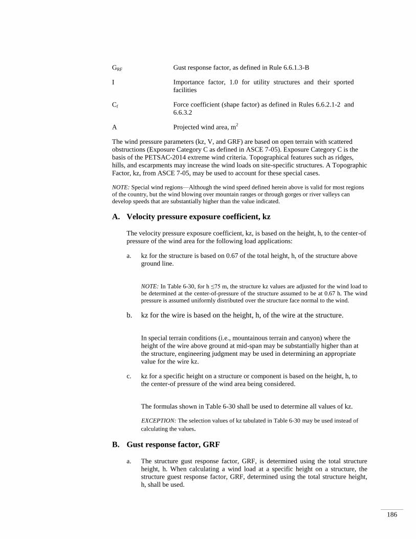
186
The wind pressure parameters (kz, V, and GRF) are based on open terrain with scattered
obstructions (Exposure Category C as defined in ASCE 7-05). Exposure Category C is the
basis of the PETSAC-2014 extreme wind criteria. Topographical features such as ridges,
hills, and escarpments may increase the wind loads on site-specific structures. A Topographic
Factor, kz, from ASCE 7-05, may be used to account for these special cases.
NOTE: Special wind regions—Although the wind speed defined herein above is valid for most regions
of the country, but the wind blowing over mountain ranges or through gorges or river valleys can
develop speeds that are substantially higher than the value indicated.
A. Velocity pressure exposure coefficient, kz
The velocity pressure exposure coefficient, kz, is based on the height, h, to the center-of
pressure of the wind area for the following load applications:
a. kz for the structure is based on 0.67 of the total height, h, of the structure above
ground line.
NOTE: In Table 6-30, for h ≤75 m, the structure kz values are adjusted for the wind load to
be determined at the center-of-pressure of the structure assumed to be at 0.67 h. The wind
pressure is assumed uniformly distributed over the structure face normal to the wind.
b. kz for the wire is based on the height, h, of the wire at the structure.
In special terrain conditions (i.e., mountainous terrain and canyon) where the
height of the wire above ground at mid-span may be substantially higher than at
the structure, engineering judgment may be used in determining an appropriate
value for the wire kz.
c. kz for a specific height on a structure or component is based on the height, h, to
the center-of pressure of the wind area being considered.
The formulas shown in Table 6-30 shall be used to determine all values of kz.
EXCEPTION: The selection values of kz tabulated in Table 6-30 may be used instead of
calculating the values.
B. Gust response factor, GRF
a. The structure gust response factor, GRF, is determined using the total structure
height, h. When calculating a wind load at a specific height on a structure, the
structure guest response factor, GRF, determined using the total structure height,
h, shall be used.
GRF Gust response factor, as defined in Rule 6.6.1.3-B
I Importance factor, 1.0 for utility structures and their sported
facilities
Cf Force coefficient (shape factor) as defined in Rules 6.6.2.1-2 and
6.6.3.2
A Projected wind area, m2

187
b. The wire gust response factor is determined using the height of the wire at the
structure, h, and the design wind span, L. Wire attachment points that are 18 m or
less above ground or water level must be considered if the total structure height is
greater than 18 m above ground or water.
In special terrain conditions (i.e., mountainous terrain ad canyon) where the height
of the wire aboveground at mid-span substantially higher than at the attachment
point, engineering judgment may be used in determining an appropriate value for
the wire GRF.
c. The gust response factor, GRF, to be used on components, such as antennas,
transformers, etc., shall be the structure gust response factor determined in Rule
6.6.1.3-Ba.
Selected values of the structure and wire gust response factors are tabulated in
Table 6-31. The structure and wire gust response factors may also be determined
using the formulas in Table 6-31. For values of h > 75 m and L > 600 m, the GRF
shall be determined using the formulas in Table 6-31.
NOTE: Where structure heights are 50 m or less and spans are 600 m or less, the combined
product of kz and GRF may be conservatively taken as 1.15 it is desired to simplify
calculations.
6.6.1.4 Extreme ice with concurrent wind loading
If no portion of a structure or its supported facilities exceeds 18 m above ground or water
level, the provisions of this rule are not required. Where a structure or its supported
facilities exceeds 18 m above ground or water level, the structure and its supported
facilities shall be designed to withstand the ice and wind load associated with the Uniform
Ice Thickness and Concurrent Wind Speed. The wind pressures for the concurrent wind
speed shall be as indicated in Table 6-32. The wind pressures calculated shall be applied to
the entire structure and supported facilities without ice and to the iced wire diameter
determined in accordance with Rule 6.6.2.
Ice is assumed to weigh 913 kg/m3.
1. For Grade B, the radial thickness of ice shall be multiplied by a factor of 1.00.
2. For Grade C, the radial thickness of ice shall be multiplied by a factor of 0.80.
3. The concurrent wind shall be applied to the projected area resulting from Rules
6.6.1.4-1 and 6.6.1.4-2 multiplied by a factor of 1.00.

188
Table 6-29: Ice, wind pressure, and temperatures
Heavy Loading Areas
Medium Loading Areas Light Loading Areas
Radial
thickness of
ice (mm)
12.5 6.5 0
Horizontal
wind
pressure
(kg/m2)
19 19 43
Temperature
(°C) -20 -10 -1~ +10

189
Table 6-30 : Velocity pressure exposure coefficient kz
Height, h (m) kz (structure) kz (wire, specified height on the structure, and
component)
≤ 10 0.9 1.0
> 10 to 15 1.0 1.1
> 15 to 25 1.1 1.2
> 25 to 35 1.2 1.3
> 35 to 50 1.3 1.4
> 50 to 75 1.4 1.5
> 75 Use formulas Use formulas
Formulas:
Structure kz = 2.01 0.67˙h/275)(2/9.5)
h ≤ 275m
kz = 1.85 h ≤ 275m
Wire, specified height on
the structure, and
Component
kz = 2.01˙(h/275)(2/9.5)
kz = 2.01
h ≤ 275m
h ≤ 275m
h = Structure, specified height on the structure, and component and wire height as defined in
Rule 6.6.1.3-A
Minimum kz = 0.85
Formulas are for exposure Category C, ASCE 7-05
NOTE: Calculations in this table are based on the maximum values in the stated ranges.

190
Table 6-31: Structure and wire gust response factors, GRF
Height Structure Wire GRF, span length, L (m)
h (m) GRF ≤75 75<L
≤150
150<L
≤225
225<L
≤300
300<L
≤450
450<L
≤600
L
>600
≤10 1.00 0.91 0.86 0.79 0.75 0.72 0.69
>10 to
15 0.96 0.87 0.82 0.76 0.73 0.70 0.67
>15 to
25 0.93 0.85 0.80 0.75 0.71 0.69 0.66
>20 to
35 0.89 0.82 0.78 0.73 0.70 0.68 0.65
>35 to
50 0.86 0.81 0.77 0.72 0.69 0.67 0.64
>50 to
75 0.83 0.79 0.75 0.71 0.68 0.66 0.63
>75
Formulas:
Where:
Structure GRF= [1 + (2.7 ˙Es ˙ Bs0.5
)]/kv2 Ew = Wire exposure factor
Wire GRF= [1 + (2.7 ˙Ew˙ Bw0.5
)]/kv2 Es = Structure exposure factor
Es = 0.346 ˙ [10/(0.67.h)]1/7
Bw = Dimensionless response term corresponding to the quasi-
static background wind loads on the structure
Ew = 0.346 ˙ (10/h)1/7
Bs = Dimensionless response term corresponding to the quasi-
static background wind loads on the structure
Bs = 1/(1+0.56 ˙ (0.67 . h)/67
kv = 1.43
Bw = 1/(1+0.8 ˙ L/67) h = Structure or wire height, as defined in Rule 6.6.1.3-B, in
meters
L = Design wind span, in meters
Formulas are for Exposure Category C, ASCE 7-05
For heights greater than 75 m and/or spans greater than 600 m, the formulas shall be used.

191
Table 6-32: Wind speed conversions to pressure
To be used only with the extreme ice with concurrent wind loading of Rule 6.6.1.4
Wind speed
(mph)
Horizontal wind pressure
kg/m2
30 11
40 19
50 31
60 44
6.6.2 Conductor loading
6.6.2.1 General
Ice and wind loads are specified in Rule 6.6.1.
1. Where a cable is attached to a messenger, the specified loads shall be applied to both
cable and messenger.
2. In determining wind loads on a conductor or cable without ice covering, the assumed
projected area shall be that of a smooth cylinder whose outside diameter is the same as
that of the conductor or cable. The force coefficient (shape factor) for cylindrical
surfaces is assumed to be 1.0.
EXCEPTION: The force coefficient (shape factor) of 1.0 may be reduced for the bare conductor
(without radial ice) if wind tunnel tests or a qualified engineering study justifies a reduction.
NOTE: Experience has shown that as the size of multi-conductor cable decreases, the actual
projected area decreases, but the roughness factor increases and offsets the reduction in
projected area.
3. An appropriate mathematical model shall be used to determine the wind and weight
loads on ice-coated conductors and cables. In the absence of a model developed in
accordance with Rule 6.6.2.1-4, the following mathematical model shall be used:
a. On a conductor, lashed cable, or multiple-conductor cable, the coating of ice
shall be considered to be a hollow cylinder touching the outer strands of the
conductor or the outer circumference of the lashed cable or multiple-conductor
cable.
b. On bundled conductors, the coating of ice shall be considered as individual
hollow cylinders around each subconductor.
4. It is recognized that the effects of conductor stranding or of non-circular cross section
may result in wind and ice loadings more or less than those calculated according to
assumptions stated in Rules 6.6.2.1-2 and 6.6.2.1-3. No reduction in these loadings is
permitted unless testing or a qualified engineering study justifies a reduction.

192
6.6.2.2 Load components
The load components shall be determined as follows:
1. Vertical load component
The vertical load on a wire, conductor, or messenger shall be its own weight plus the
weight of conductors, spacers, or equipment that it supports, ice covered where required
by Rule 6.6.1.
2. Horizontal load component
The horizontal load shall be the horizontal wind pressure determined under Rule 6.6.1
applied at right angles to the direction of the line using the projected area of the
conductor or messenger and conductors, spacers, or equipment that it supports, ice
covered where required by Rule 6.6.1.
NOTE: The projected area of the conductor or messenger is equal to the diameter of the conductor
or messenger, plus ice if appropriate, multiplied by the span length (see Rule 6.6.3.2-D). See Rule
6.6.2.1-2 for force coefficient values of different surface shapes.
3. Total load
The total load on each wire, conductor, or messenger shall be the resultant of
components 1 and 2 above, calculated at the applicable temperature in Table 6-33, plus
the corresponding constant in Table 6-33. In all cases the conductor or messenger
tension shall be computed from this total load.

193
Table 6-33: Temperatures and constants
Loading (for use with Rule 6.6.1.2)
Heavy Loading
Areas
Medium Loading
Areas
Light Loading Areas
Temperature (°C) -20 -10 -1
Constant to be added
to the resultant
(all
conductors)(kg/m2)
0.44 0.29 0.073
For cable arrangements supported by a messenger using spacers or rings and where each conductor or cable is
separately loaded with ice and wind as described in Rule 6.6.2.1-3b as opposed to being analyzed with the ice and
wind applied to a hollow cylinder touching the outer strands of the conductors as described in Rule 6.6.2.1-3a, the
constant specified here shall be added to the resultant load of each component conductor and the messenger
6.6.3 Loads on line supports
6.6.3.1 Assumed vertical loads
The vertical loads on poles, towers, foundations, crossarms, pins, insulators, and conductor
fastenings shall be their own weight plus the weight that they support, including all wires
and cables, in accordance with Rules 6.6.2.1 and 6.6.2.2-1, together with the effect of any
difference in elevation of supports. Loads due to radial ice shall be computed on wires,
cables, and messengers, but need not be computed on supports.
6.6.3.2 Assumed transverse loads
The total transverse loads on poles, towers, foundations, crossarms, pins, insulators, and
conductor fastenings shall include the following:
A. Transverse loads from conductors and messengers
The transverse loads from conductors and messengers shall be the horizontal load
determined by Rule 6.6.2.
EXCEPTION: In medium- and heavy-loadings, where supporting structures carry ten or more
conductors on the same crossarm, not including cables supported by messengers, and where the
horizontal pin spacing does not exceed 380 mm (15 in), the transverse wind load may be calculated
on two-thirds of the total number of such conductors if at least ten conductors are used in the
calculations.
B. Wind loads on structures
The transverse load on structures and equipment shall be computed by applying, at right
angles to the direction of the line, the appropriate horizontal wind pressure determined
under Rule 6.6.1. This load shall be calculated using the projected surfaces of the
structures and equipment supported thereon, without ice covering. The following force
coefficient (shape factors) shall be used.

194
a. Cylindrical structures and components
Wind loads on straight or tapered cylindrical structures or structures composed of
numerous narrow relatively flat panels that combine to form a total cross section that is
circular or elliptical in shape shall be computed using a force coefficient (shape factor)
of 1.0.
b. Flat surfaced (not latticed) structures and components
Wind loads on structures or components, having solid or enclosed flat sided cross
sections that are square or rectangular, with rounded corners, shall be computed using a
force coefficient (shape factor) of 1.6.
c. Latticed structures
Wind loads on square or rectangular latticed structures or components shall be
computed using a force coefficient (shape factor) of 3.2 on the sum of the projected
areas of the members of the front face if structural members are flat surfaced or 2.0 if
structural surfaces are cylindrical. The total, however, need not exceed the load that
would occur on a solid structure of the same outside dimension.
EXCEPTION: The force coefficient (shape factor) listed under Rules 6.6.3.2-Ba, 6.6.3.2-Bb, and
6.6.3.2-Bc may be reduced if wind tunnel tests or a qualified engineering study justifies a
reduction.
C. At angles
Where a change in direction of wires occurs, the loads on the structure, including guys,
shall be the vector sum of the transverse wind load and the wire tension load. In
calculating these loads, a wind direction shall be assumed that will give the maximum
resultant load. Proper reduction may be made to the loads to account for the reduced wind
pressure on the wires resulting from the angularity of the application of the wind on the
wire.
D. Span lengths
The calculated transverse load shall be based on the average of the two spans adjacent to
the structure concerned.
6.6.3.3 Assumed longitudinal loading
A. Change in grade of construction
The longitudinal loads on supporting structures, including poles, towers, and guys at the
ends of sections required to be of Grade B construction, when located in lines of lower
than Grade B construction, shall be taken as an unbalanced pull in the direction of the
higher grade section equal to the larger of the following values:
a. Conductors with rated breaking strength of 13.3 kN or less The unbalanced tension
shall be the tension of two-thirds, but not fewer than two, of the conductors having a
rated breaking strength of 13.3 kN or less. The conductors selected shall produce the
maximum stress in the support.

195
EXCEPTION: Where there are one or two conductors having rated breaking strength of 13.3 kN
or less, the load shall be that of one conductor.
b. Conductors with rated breaking strength of more than 13.3 kN. The pull resulting
from one conductor when there are eight or less conductors (including overhead
ground wires) having rated breaking strength of more than 13.3 kN, and the pull of
two conductors when there are more than eight conductors. The conductors selected
shall produce the maximum stress in the support.
B. Jointly used poles at crossings over railroads, telecommunication
lines, or limited access highways
Where a joint line crosses a railroad, a telecommunication line, or a limited access
highway, and Grade B is required for the crossing span, the tension in the
telecommunication conductors of the joint line shall be considered as limited to one-half
their rated breaking strength, provided they are smaller than Stl WG No. 8 if of steel, or
AWG No. 6 if of copper.
C. Deadends
The longitudinal load on a supporting structure at a deadend shall be an unbalanced pull
equal to the tensions of all conductors and messengers (including overhead ground wires);
except that with spans in each direction from the dead-end structure, the unbalanced pull
shall be the difference in tensions.
D. Unequal spans and unequal vertical loads
The structure should be capable of supporting the unbalanced longitudinal load created by
the difference in tensions in the wires in adjacent spans caused by unequal vertical loads
or unequal spans.
E. Stringing loads
Consideration should be given to longitudinal loads that may occur on the structure
during wire stringing operations.
F. Longitudinal capability
It is recommended that structures having a longitudinal strength capability be provided at
reasonable intervals along the line.
G. Telecommunication conductors on unguyed supports at railroad and
limited access highway crossings.
The longitudinal load shall be assumed equal to an unbalanced pull in the direction of the
crossing of all open-wire conductors supported, the pull of each conductor being taken as
50% of its rated breaking strength in the heavy loadings, 33-1/3% in the medium
loadings, and 22-1/4% in the light-loadings.
6.6.3.4 Simultaneous application of loads
Where a combination of vertical, transverse, or longitudinal loads may occur
simultaneously, the structure shall be designed to withstand the simultaneous application of
these loads.
NOTE: Under the extreme wind conditions of Rule 6.6.1.3, an oblique wind may require greater
structural strength than that computed by Rules 6.6.3.2 and 6.6.3.3.

196
6.6.4 Load factors for structures, crossarms, support hardware, guys,
foundations, and anchors
Loads in Rule 6.6.1.2, the extreme wind loading condition in Rule 6.6.1.3, and the extreme ice
with concurrent wind condition in Rule 6.6.1.4 shall be multiplied by the load factors in Table 6-
34.
Table 6-34: Load factors for structures, crossarms, support hardware, guys,
foundations, and anchors to be used with the strength factors of Table 6-35
Load Factors
Grade B Grade C
At crossings Elsewhere
Rule 6.6.1.2 loads
(Combined ice and wind
loadings)
Vertical loads
1.50 1.90 1.90
Transverse loads
Wind
Wire tension
2.50
1.65
2.20
1.30
1.75
1.30
Longitudinal loads
In general
At deadends
1.10
1.65
No requirement
1.30
No requirement
1.30
Rule 6.6.1.3 load
(Extreme wind)
Wind loads
All other loads
1.00
1.00
0.87
1.00
0.87
1.00
Rule 6.6.1.4 loads
(Extreme ice with
concurrent wind)
1.00
1.00
1.00
Includes pole.
For guys and anchors associated with structures supporting telecommunication conductors and cables only, this
factor may be reduced to 1.33.
Where vertical loads significantly reduce the stress in a structure member, a vertical load factor of 1.0 should be
used for the design of such member. Such member shall be designed for the worst case loading.
For metal or prestressed concrete, portions of structures, crossarms, guys, foundations, and anchors, use a value of
1.10.
For metal prestressed concrete, or fiber-reinforced polymer portions of structures and crossarms, guys, foundations,
and anchors, use a value of 1.50.
This applies only where a line crosses another supply or telecommunication line (see Rule 6.5.2.3 and Table 6-28).
For wind velocities above 160 km/hour, a factor of 0.75 may be used.
Support hardware does not include insulators. See Rule 6.8 for insulator strength and loading requirements.

197
6.7 Strength requirements
6.7.1 General
6.7.1.1 Preliminary assumptions
1. It is recognized that deformation, deflections, or displacement of parts of the structure
may change the effects of the loads assumed. In the calculation of stresses, allowance
may be made for such deformation, deflection, or displacement of supporting structures
including poles, towers, guys, crossarms, pins, conductor fastenings, and insulators when
the effects can be evaluated. Such deformation, deflection, or displacement should be
calculated using Rule 6.6.1 loads prior to application of the load factors in Rule 6.6.4. For
crossings or conflicts, the calculations shall be subject to mutual agreement.
NOTE: Depending upon the characteristics of the structural material, significant sustained
(everyday) stress (such as stresses produced by gravity or tension loads) can decrease the strength
during the expected life of the material and may require guying or bracing to be able to meet the
required strength capability.
2. It is recognized that new materials may become available. While these materials are in the
process of development, they must be tested and evaluated. Trial installations are
permitted where the requirements of Rule 1.5.1-2 are met.
6.7.1.2 Application of strength factors
1. Supporting structures and structural components shall be designed to withstand the
appropriate loads multiplied by the load factors in Rule 6.6 without exceeding their
strength multiplied by the strength factors in Table 6-35.
EXCEPTION: For insulators, see Rule 6.8 for strength and loading requirements.
NOTE 1: The latest edition of the following document may be used for providing information for
determining the 5% lower exclusion limit strength of a FRP structure or component for use with an
appropriate strength factor (Table 6-35) and the specified PETSAC loads and load factors (Table 6-
34): ASCE-111, Reliability-Based Design of Utility Pole Structures.
NOTE 2: The latest edition (unless a specific edition is referenced) of the documents (Appendix-A)
are among those available for determining structure design capacity with the specified PETSAC-
2014 loads, load factors, and strength factors:
2. Where strength factors are not defined in Rule 6.7.2, a strength factor of 0.80 shall be
used for the extreme wind loading conditions specified in Rule 6.6.1.3 and for the
extreme ice with concurrent wind specified in Rule 6.6.1.4 for all supported facilities.
6.7.2 Grades B and C construction
6.7.2.1 Supporting structures
The strength requirements for supporting structures may be met by the structures alone or
with the aid of guys or braces or both.
A. Metal, prestressed-, and reinforced-concrete structures

198
a. These structures shall be designed to withstand the loads in Rule 6.6.3 multiplied by the
appropriate load factors in Table 6-34 without exceeding the permitted stress.
NOTE: When determining required strength for axial loads, buckling needs to be considered.
b. The permitted stress shall be the strength multiplied by the strength factors in Table 6-
35 (where guys are used, see Rule 6.7.2.3.
c. All structures including those below 18 m shall be designed to withstand, without
conductors, the extreme wind load in Rule 6.6.1.3 applied in any direction on the
structure and any supported facilities and equipment that may be in place prior to
installation of conductors.
d. Spliced and reinforced structures
Reinforcements or permanent splices to a supporting structure are permitted provided
they develop the required strength of the structure.
B. Wood structures
Wood structures shall be of material and dimensions to meet the following requirements:
a. Wood structures shall be designed to withstand the loads in Rule 6.6.1.3 multiplied by
the appropriate load factors in Table 6-34 without exceeding the permitted stress level
at the point of maximum stress.
EXCEPTION 1: When installed, unguyed naturally grown wood poles 16.8 m or less in total
length, acting as single-based structures or unbraced multiple-pole structures, shall meet the
requirements of Rule 6.7.2.1-Ba without exceeding the permitted stress level at the ground line.
However, all guyed poles, regardless of length, shall meet the requirements of Rule 6.7.2.1-Ba
without exceeding the permitted stress level at points of attachment for guy and guy struts.
EXCEPTION 2: At a Grade B crossing, in a straight section of line, wood structures complying
with the transverse strength requirements of Rule 6.7.2.1-Ba without the use of transverse guys,
shall be considered as having the required longitudinal strength, providing the longitudinal
strength is comparable to the transverse strength of the structure. This EXCEPTION does not
modify the requirements of this rule for deadends.
EXCEPTION 3: At a Grade B crossing of a supply line over a highway or a telecommunication
line where there is an angle in the supply line, wood structures shall be considered as having the
required longitudinal strength if all of the following conditions are met:
(a) The angle is not over 20 degrees.
(b) The angle structure is guyed in the plane of the resultant of the conductor tensions. The
tension in this guy under the loading in Rule 6.7.2.1-Ba multiplied by a load factor of 2.0
shall not exceed the rated breaking strength multiplied by the strength factor in Table 6-35.
(c) The angle structure has sufficient strength to withstand, without guys, the transverse loading
of Rule 6.6.3 multiplied by the appropriate load factors in Table 6-34 which would exist if
there were no angle at that structure without exceeding the permitted stress level.
NOTE: When determining a fiber stress for axial loads, buckling needs to be considered.
b. Permitted stress level
(1) Natural wood pole

199
The permitted stress level of natural wood poles of various species meeting the
requirements of ANSI O5.1-2008 shall be determined by multiplying the designated
fiber strength set forth in that standard by the appropriate strength factors in Table 6-
35.
(2) Sawn or laminated wood structural members, crossarms, and braces.
The permitted stress level of sawn or laminated wood structural members,
crossarms, and braces meeting the requirements of ANSI O5.2-2006 [B16] or ANSI
O5.3-2008 [B17] shall be determined by multiplying the appropriate designated
fiber stress set forth in the respective standard, by the appropriate strength factors in
Table 6-35.
c. Strength of guyed poles
Guyed poles shall be designed as columns, resisting the vertical component of the
tension in the guy plus any other vertical loads.
d. Spliced and reinforced poles
Reinforcements or permanent splices at any section along the pole are permitted
provided they develop the required strength of the pole.
e. All structures including those below 18 m shall be designed to withstand, without
conductors, the extreme wind load in Rule 6.6.1.3 applied in any direction on the
structure and any supported facilities and equipment which may be in place prior to
installation of conductors.
C. Fiber-reinforced polymer structures
a. These structures shall be designed to withstand the loads in Rule 6.6.3 multiplied by the
appropriate load factors in Table 6-34 without exceeding the permitted load.
NOTE: When determining a fiber stress for axial loads, buckling needs to be considered.
b. The permitted load shall be the 5th percentile strength (i.e., “5% lower exclusion limit”)
or less, multiplied by the strength factors in Table 6-35 (where guys are used, see Rule
6.7.2.3).
c. Spliced and reinforced poles
Reinforcements or permanent splices to a supporting pole are permitted provided they
develop the required strength of the pole.
d. All structures including those below 18 m shall be designed to withstand, without
conductors, the extreme wind load in Rule 6.6.1.3 applied in any direction on the
structure and any supported facilities and equipment which may be in place prior to
installation of conductors.
D. Transverse strength requirements for structures where side guying is
required, but can be installed only at a distance
Grade B: If the transverse strength requirements of this section cannot be met except by
the use of side guys or special structures, and where it is physically impractical to employ

200
side guys, the transverse strength requirements may be met by side-guying the line at
each side of, and as near as practical to, the crossing, or other transversely weak structure,
and with a distance between such side-guyed structures of not over 250 m, provided that:
a. The side-guyed structures for each such section of 250 m or less shall be designed to
withstand the calculated transverse load due to wind on the supports and ice-covered
conductors, on the entire section between side-guyed structures.
b. The line between such side-guyed structures shall be substantially in a straight line
and the average span between the side-guyed structures shall not exceed 45 m.
c. The entire section between the structures with the required transverse strength shall
comply with the highest grade of construction concerned in the given section, except
as to the transverse strength of the intermediate poles or towers.
Grade C: The above provisions do not apply to Grade C.
E. Longitudinal strength requirements for sections of higher grade in
lines of a lower grade construction
a. Methods of providing longitudinal strength
Grade B: The longitudinal strength requirements for sections of line of higher grade in
lines of a lower grade (for assumed longitudinal loading, see Rule 6.6.3 may be met
by placing a structure of the required longitudinal strength at each end of the higher
grade section.
Where this is impractical, the structures of the required longitudinal strength may be
located away from the section of higher grade, within 150 m on each side and with not
more than 250 m between the structures of the required longitudinal strength. This is
permitted provided the following conditions are met:
(1) The structures and the line between them meet the requirements for transverse
strength and stringing of conductors of the highest grade occurring in the section,
and
(2) The line between the structures of the required longitudinal strength is
approximately straight or suitably guyed.
The longitudinal strength requirement of the structures may be met by using
guys.
Grade C: The above provisions do not apply to Grade C.
b. Flexible supports
Grade B: When supports of the section of higher grade are capable of considerable
deflection in the direction of the line, it may be necessary to increase the clearances
required in Rule 6.4 or to provide line guys or special reinforcements to reduce the
deflection.

201
Grade C: The above provision does not apply to Grade C.
6.7.2.2 Strength of foundations, settings, and guy anchors
Foundations, settings, and guy anchors shall be designed or be determined by experience to
withstand the loads in Rule 6.6.3 multiplied by the load factors in Table 6-34 without
exceeding the permitted load. The permitted load shall be equal to the strength multiplied
by the strength factors in Table 6-35.
NOTE 1: Excessive movement of foundations, settings, and guy anchors or errors in settings can
reduce clearances or structure capacity.
NOTE 2: Soil saturation can have an adverse effect on the strengths of foundations, settings, and guy
anchors.
6.7.2.3 Strength of guys and guy insulators
The strength requirements for guys and guy insulators are covered under Rules 6.7.4 and
6.8.9.1-Ac respectively.
A. Metal and prestressed-concrete structures
Guys shall be considered as an integral part of the structure.
B. Wood and reinforced-concrete structures
When guys are used to meet the strength requirements, they shall be considered as taking
the entire load in the direction in which they act, the structure acting as a strut only,
except for those structures considered to possess sufficient rigidity so that the guy can be
considered an integral part of the structure.
NOTE: Excessive movement of guys can reduce clearances or structure capacity.
C. Fiber-reinforced polymer structures
When guys are used to meet the strength requirements, the guys shall be considered as
taking the entire load in the direction in which they act, as if the structure is acting as a
strut only, except for those structures considered to possess sufficient rigidity so that the
guys can be considered an integral part of the structure.
NOTE: Excessive movement of guys can reduce clearances or structure capacity.
6.7.2.4 Crossarms and braces
A. Concrete and metal crossarms and braces
Crossarms and braces shall be designed to withstand the loads in Rule 6.6.3 multiplied by
the load factors in Table 6-34 without exceeding the permitted load. The permitted load
shall be equal to the strength multiplied by the strength factors in Table 6-34.
B. Wood crossarms and braces
a. Strength

202
(1) Crossarms and braces shall be designed to withstand the loads in Rule 6.6.3
multiplied by the load factors in Table 6-34 without exceeding their permitted
stress.
(2) The permitted stress level of solid sawn or laminated wood crossarms and braces
shall be determined by multiplying their ultimate fiber stress by the strength
factors in Table 6-35.
b. Material and size
Wood crossarms and braces of selected wood shall have a cross section of not less
than those in Table 6-35. Crossarms of other species may be used provided they
have equal strength.
C. Fiber-reinforced polymer crossarms and braces
Crossarms and braces shall be designed to withstand the loads in Rule 6.6.3 multiplied
by the load factors in Table 6-34 without exceeding the permitted load. The permitted
load shall be the 5th percentile strength (i.e., “5% lower exclusion limit”) or less,
multiplied by the strength factors in Table 6-35.
D. Crossarms and braces of other materials
Crossarms and braces should meet the strength requirements of Rule 6.7.2.4-B.
E. Additional requirements
a. Longitudinal strength
(1) General
(a) Crossarms shall be designed to withstand a load of 3.1 kN applied at the
outer conductor attachment point without exceeding the permitted stress level
for wood crossarms or the permitted load for crossarms of other materials, as
applicable.
(b) At each end of a transversely weak section, as described in Rule 6.7.2.1-D
the longitudinal load shall be applied in the direction of the weak section.
(2) Methods of meeting Rule 6.7.2.4-Ba(1)
Grade B: Where conductor tensions are limited to a maximum of 9.0 kN per
conductor, double wood crossarms having cross sections in Table 6-31 and
properly assembled will comply with the longitudinal strength requirements in
Rule 6.7.2.4-Ba(1).
Grade C: This requirement is not applicable.
(3) Location
At crossings, crossarms should be mounted on the face of a pole away from the
crossing, unless special bracing or double crossarms are used.
b. Bracing

203
Crossarms shall be supported by bracing, if necessary, to support expected loads,
including line personnel working on them. Crossarm braces used only to sustain
unbalanced vertical loads need only to be designed for these unbalanced vertical
loads.
c. Double crossarms, brackets, or equivalent support assembly
Grade B: Where pin-type construction is used, double wood crossarms, each crossarm
having the strength required by Rule 6.7.2.4-Ba(1), or a support assembly equivalent
in strength to double wood crossarms shall be used at each crossing structure, at ends
of joint use or conflict sections, at deadends, and at corners where the angle of
departure from a straight line exceeds 20 degrees. Under similar conditions, where a
bracket supports a conductor operated at more than 750 V to ground and there is no
crossarm below, double brackets or a support assembly equivalent in strength to
double wood crossarms shall be used.
EXCEPTION: The above does not apply where telecommunication cables or conductors cross
below supply conductors and either are attached to the same pole, or where supply conductors
are continuous and of uniform tension in the crossing span and each adjacent span. This
exception does not apply to railroad crossings and limited access highways except by mutual
agreement.
Grade C: The above requirement is not applicable.
6.7.2.5 Insulators
The strength requirements for insulators are covered under Rules 6.8.8 and 6.8.9.
6.7.2.6 Strength of pin-type or similar construction and conductor fastenings
A. Longitudinal strength
a. General
Pin-type or similar construction and ties or other conductor fastenings shall be designed
to withstand the applicable longitudinal loads in Rule 6.6.3, multiplied by the load
factors for longitudinal loads in Table 6-34, or 3.1 kN applied at the pin, whichever is
greater.
b. Method of meeting Rule 6.7.2.6-Aa
Grade B: Where conductor tensions are limited to 9.0 kN and such conductors are
supported on pin insulators, double wood pins and ties or their equivalent will be
considered to meet the requirements of Rule 6.7.2.6-Aa.
Grade C: No requirement.
c. At deadends and at ends of higher grade construction in line of lower grade
Grade B: Pins and ties or other conductor fastenings connected to the structure at a
deadend or at each end of the higher grade section shall be designed to withstand an
unbalanced pull due to the conductor load in Rule 6.6.2 multiplied by the load factors in
Rule 6.6.4.

204
Grade C: This requirement is not applicable except for deadends.
d. At ends of transverse sections described in Rule 6.7.2.1-D
Grade B: Pins and ties or other conductor fastenings connected to the structure at ends
of the transverse section as described in Rule 6.7.2.1-D shall be designed to withstand
the unbalanced pull in the direction of that transverse section under the load in Rule
6.6.3 multiplied by the load factors in Rule 6.6.4.
Grade C: No requirement.
B. Double pins and conductor fastenings
Grade B: Double pins and conductor fastenings shall be used where double crossarms
or brackets are required by Rule 6.7.2.4-D.
EXCEPTION: The above does not apply where telecommunication cables or conductors cross
below supply conductors and either are attached to the same pole, or where supply conductors are
continuous and of uniform tension in a crossing span and each adjacent span. This exception does
not apply in the case of railroad crossings and limited access highway crossings except by mutual
agreement.
Grade C: No requirement.
C. Single supports used in lieu of double wood pins
A single conductor support and its conductor fastening, when used in lieu of double
wood pins, shall develop strength equivalent to double wood pins and their conductor
fastenings as specified in Rule 6.7.2.6-Aa.
6.7.2.7 Armless construction
A. General
Open conductor armless construction is a type of open conductor supply line
construction in which conductors are individually supported at the structure without the
use of crossarms.
B. Insulating material
Strength of insulating material shall meet the requirements of Rule 6.7.
C. Other components
Strengths of other components shall meet the requirements of Rules 6.7.1 and 6.7.2.
6.7.2.8 Open supply conductors and overhead shield wires
A. Tensions
a. The supply conductor and overhead shield wire tensions shall be not more than 60%
of their rated breaking strength for the load of Rule 6.6.1.2 in Rule 6.6.2 multiplied by
a load factor of 1.0. If Rules 6.6.1.3 and 6.6.1.4 are applicable, the supply conductor
and overhead shield wire tensions for these loading cases shall not be stressed beyond
80% of their rated breaking strength under the loads of Rules 6.6.1.3 and 6.6.1.4 in
Rule 6.6.2 multiplied by a load factor of 1.0.

205
b. The tension at the applicable temperature listed in Table 6-33, without external load,
shall not exceed the following percentages of their rated breaking strength:
Initial unloaded tension 35%
Final unloaded tension 25%
EXCEPTION 1: The initial and final unloaded tension limits may be used at higher
temperatures not to exceed 15°C if (a) vibration control devices or self-damping conductors are
appropriately used, or (b) a qualified engineering study, manufacturer’s recommendation, or
experience indicated aeolian vibration damage is not likely to occur.
EXCEPTION 2: In the case of conductors with a generally triangular cross section, such as
cables composed of three wires, the final unloaded tension at the applicable temperature listed
in Table 6-33 shall not exceed 30% of the rated breaking strength of the conductor.
NOTE: The above limitations may not protect the conductor or facilities from damage due to
aeolian vibration.
B. Splices, taps, dead-end fittings, and associated attachment hardware
a. Splices should be avoided in crossings and adjacent spans. If it is impractical to avoid
such splices, they shall have sufficient strength to withstand the maximum tension
resulting from the loads of Rule 6.6.1.2 in Rule 6.6.2 multiplied by a load factor of
1.65. If Rules 6.6.1.3 and 6.6.1.4 are applicable, splices shall not be stressed beyond
80% of their rated breaking strength under the loads of Rules 6.6.1.3 and 6.6.1.4 in
Rule 6.6.2 multiplied by a load factor of 1.0.
b. Taps should be avoided in crossing spans but, if required, shall be of a type that will
not impair the strength of the conductors to which they are attached.
c. Dead-end fittings, including the associated attachment hardware, shall have sufficient
strength to withstand the maximum tension resulting from the loads of Rule 6.6.1.2 in
Rule 6.6.2 multiplied by a load factor of 1.65. If Rules 6.6.1.3 and 6.6.1.4 are
applicable, deadend fittings shall not be stressed beyond 80% of their rated breaking
strength under the loads of Rules 6.6.1.3 and 6.6.1.4 in Rule 6.6.2 multiplied by a load
factor of 1.0.
C. Trolley-contact conductors
In order to provide for wear, no trolley-contact conductor shall be installed of less size
than AWG No. 0, if of copper, or AWG No. 4, if of silicon bronze.
6.7.2.9 Supply cable messengers
Messengers shall be stranded and shall not be stressed beyond 60% of their rated breaking
strength under the loads of Rule 6.6.1.2 in Rule 6.6.2 multiplied by a load factor of 1.0. If
Rules 6.6.1.3 and 6.6.1.4 are applicable, messengers shall not be stressed beyond 80% of
their rated breaking strength under the loads of Rules 6.6.1.3 and 6.6.1.4 in Rule 6.6.2
multiplied by a load factor of 1.0.
NOTE: There are no strength requirements for cables supported by messengers.
6.7.2.10 Open-wire telecommunication conductors
Open-wire telecommunication conductors in Grade B or C construction shall have the
tensions in Rule 6.7.2.8-A for supply conductors of the same grade.

206
EXCEPTION: Where supply conductors are trolley-contact conductors of 0 to 750 V to ground, WG
No. 12 Stl may be used for telecommunication conductors for spans of 0 to 30 m, and Stl WG No. 9
may be used for spans of 38 to 45 m.
6.7.2.11 Telecommunication cables and messengers
A. Telecommunication cables
a. There are no strength requirements for telecommunication cables supported by
messengers. See Rule 6.7.2.11-B for the strength requirements for messengers
supporting telecommunication cables.
b. Self-supporting cables shall not be stressed beyond the limits stated in Rule 6.7.2.1-D
c. For paired metallic telecommunication conductors, see Rule 6.7.2.12.
B. Messenger
The messenger shall not be stressed beyond 60% of its rated breaking strength under the
loads of Rule 6.7.1.2 in Rule 6.6.2 multiplied by a load factor of 1.0. If Rules 6.6.1.3
and 6.6.1.4 are applicable, messengers shall not be stressed beyond 80% of their rated
breaking strength under the loads of Rules 6.6.1.3 and 6.6.1.4 multiplied by a load
factor of 1.0.
6.7.2.12 Paired metallic telecommunication conductors
A. Paired conductors supported on messenger
a. Use of messenger
A messenger may be used for supporting paired conductors in any location, but is
required for paired conductors crossing over trolley-contact conductors of more than
7.5 kV to ground.
b. Tension of messenger
Messenger used for supporting paired conductors required to meet Grade B
construction because of crossing over trolley-contact conductors shall meet the
tension requirements for Grade B.
c. Size and sag of conductors
There are no requirements for paired conductors when supported on messenger.
B. Paired conductors not supported on messenger
a. Above supply lines
Grade B: Tensions shall not exceed those in Rule 6.7.2.8-A for supply conductors of
similar grade.
Grade C: Sizes and tensions
Spans 0 to 30 m —No requirements.
Each conductor shall have a rated breaking strength of not less than 0.75 kN.
Spans 30 to 45 m — Tensions shall not exceed those required for Grade B
telecommunication conductors.

207
Spans exceeding 45 m—Tensions shall not exceed those required for Grade C supply
conductors. (See Rule 6.7.2.8-A)
b. Above trolley-contact conductors
Grade B: Sizes and tensions
Spans 0 to 30 m—No size requirements. Tensions shall not exceed those of Rule
6.7.2.8-A
Spans exceeding 30 m—Each conductor shall have a rated breaking strength of not
less than 0.75 kN. Tensions shall not exceed those of Rule 6.7.2.8-A
Grade C: Sizes and tensions
Spans 0 to 30 m —No requirements.
Spans exceeding 30 m —No tension requirements.
Each conductor shall have a rated breaking strength of not less than 0.75 kN.
6.7.2.13 Support and attachment hardware
The strength required for all support and attachment hardware not covered by Rule
6.7.2.6 or 6.7.2.8-B shall be not less than the load times the appropriate load factor given
in Rule 6.6 and the load factor shall not be less than 1.0. For appropriate strength factors,
see Rule 6.7.1.2.
6.7.2.14 Climbing and working steps and their attachments to the structure
The strength required for all climbing devices (includes steps, ladders, platforms and their
attachments) shall be capable of supporting 2.0 times the maximum intended load. Unless
otherwise quantified by the owner, the maximum intended load shall be assumed to be
1.36 kg, which includes the weight of the lineman, harness, tools, and equipment being
supported by the lineman.
NOTE: See IEEE Std 1307™-2004 [B55].
Table 6-35: Strength factors for structures, crossarms, braces, support hardware,
guys, foundations, and anchors
[It is recognized that structures will experience some level of deterioration after installation,
depending upon materials, maintenance, and service conditions. The table values specify
strengths required at installation. Footnotes specify deterioration allowed, if any. When new or
changed facilities add loads to existing structures (a) the strength of the structure when new shall
have been great enough to support the additional loads and (b) the strength of the deteriorated
structure shall exceed the strength required at replacement. If either (a) or (b) cannot be met, the
structure must be replaced, augmented, or rehabilitated.]
Grade B Grade C
Strength factors for use with loads of Rule 6.6.1.2 (combined ice and wind loadings)
Metal and prestressed-concrete structures, crossarms, and braces 1.0 1.0
Wood and reinforced-concrete structures, crossarms, and braces 0.65 0.85
Fiber-reinforced polymer structures, crossarms, and braces 1.0 1.0
Support hardware 1.0 1.0

208
① Includes poles.
② Wood and reinforced concrete structures shall be replaced or rehabilitated when deterioration reduces the structure
strength to 2/3 of that required when installed. When new or changed facilities modify loads on existing structures,
the required strength shall be based on the revised loadings. If a structure or component is replaced, it shall meet the
strength required by Table 6-350 Rehabilitated portions of structures shall have strength greater than 2/3 of that
required when installed.
③ Wood and reinforced structures shall be replaced or rehabilitated when deterioration reduces the structure strength
to 3/4 of that required when installed. When new or changed facilities modify loads on existing structures, the
required strength shall be based on the revised loadings. If a structure or component is replaced, it shall meet the
strength required by Rule 6.7.2.8-A. If a structure or component is rehabilited, rehabilitated portions of structures
shall have strength greater than 3/4 of that required when installed.
④ Where a wood or reinforced concrete structure is built for temporary service, the structure strength may be reduced
to values as low as those permitted by footnotes (2) and (3) provided the structure strength does not decrease below
the minimum required during the planned life of the structure.
⑤ For guy insulator requirements, see Rule 6.8.9.
⑥ Deterioration during service shall not reduce strength capability below the required strength.
Table 5-36 : Dimensions of crossarm cross section of selected wood
6.7.3 Grade N construction
The strength of Grade N construction need not be equal to or greater than Grade C.
6.7.3.1 Poles
Poles used for lines for which neither Grade B nor C is required shall be of initial size or
guyed or braced to withstand expected loads, including line personnel working on them.
6.7.3.2 Guys
The general requirements for guys are covered in Rules 6.7.4 and 6.8.9.1.
6.7.3.3 Crossarm strength
Crossarms shall be securely supported by bracing, if necessary, to withstand expected loads,
including line personnel working on them.
Guy wire 0.9 0.9
Guy anchor and foundation 1.0 1.0
Strength factors for use with loads of Rules 6.6.1.3 (extreme wind) and 6.6.1.4 (extreme ice with
concurrent wind loadings)
Metal and prestressed-concrete structures, crossarms, and braces 1.0 1.0
Wood and reinforced-concrete structures, crossarms, and braces 0.75 0.75
Fiber-reinforced polymer structures, crossarms, and braces 1.0 1.0
Support hardware 1.0 1.0
Guy wire 0.9 0.9
Guy anchor and foundation 1.0 1.0
Crossarm length Grades of construction
Grade B Grade C
1.20 m or less mm: 75 x 100 70 x 95
2.45 m mm: 80 x 110 75 x 100
3.0 m mm: 80 x 110 75 x 100

209
NOTE: Double crossarms are generally used at crossings, unbalanced corners, and dead ends, in order
to permit conductor fastenings at two insulators to limit the opportunity for slipping, although single
crossarms might provide sufficient strength. To secure extra strength, double crossarms are frequently
used, and crossarm guys are sometimes used.
6.7.3.4 Supply line conductors
A. Size
Supply-line conductors shall be not smaller than the sizes listed in Table 6-37.
RECOMMENDATION: It is recommended that these sizes for copper and steel not be used in spans
longer than 45 m for the heavy-loadings, and 53 m for the medium- and light-loadings.
6.7.3.5 Service drops
A. Size of open-wire service drops
a. Not over 750 V.
Service drops shall be as required by (1) or (2):
(1) Spans not exceeding 45 m
Sizes shall be not smaller than those in Table 6-38.
(2) Spans exceeding 45 m
Sizes shall be not smaller than 8 AWG.
b. Exceeding 750 V
Sizes of service drops of more than 750 V shall be not less than required for supply
line conductors of the same voltage.
B. Tension of open-wire service drops
The tension of the service drop conductors shall not exceed the strength of the conductor
attachment or its support under the expected loads.
C. Cabled service drops
Service conductors may be grouped together in a cable, provided the following
requirements are met:
a. Size
The size of each conductor shall be not less than required for drops of separate conductors
(Rule 6.7.3.5-A).
b. Tension of cabled service drops
The tension of the service drop conductors shall not exceed the strength of the conductor
attachment or its support under the expected loads.
6.7.3.6 Trolley-contact conductors
In order to provide for wear, trolley-contact conductors shall be not smaller than size AWG
No. 0, if of copper, or AWG No. 4, if of silicon bronze.

210
6.7.3.7 Telecommunication conductors
There are no specific requirements for Grade N telecommunication line conductors or service
drops.
6.7.3.8 Street and area lighting equipment
The lowering rope or chain for luminaires arranged to be lowered for examination or
maintenance shall be of a material and strength designed to withstand climatic conditions and
to sustain the luminaire safely.
6.7.3.9 Insulators
The strength requirements for insulators are covered under Rules 6.8.7 and 6.8.9.
Table 6-37: Sizes for Grade N supply line conductors
① Copper or aluminum.
② Steel.
Table 6-38: Sizes of service drops of 750 V or less
(Voltages of trolley-contact conductors are voltage to ground.
AWG used for aluminum and copper wires; Stl WG used for steel wire.)
Installation of service drops of not more than 750 V above supply lines of more than 750 V should be avoided
where practical.
ACSR or high-strength aluminum alloy conductor size shall be not less than No. 6.
6.7.4 Guying and bracing
Material Required AWG
or Stl WG
Soft copper 6
Medium or hard drawn copper 8
Steel 9
Stranded aluminum:
EC 2
ACSR 4
ALLOY 4
ACAR 2
Copper wire
Situation Soft-drawn Medium or
Hard drawn Steel wire
EC
aluminum
wire
Along 10 12 12 4
Concerned with telecommunication
conductor
10 12 12 4
Over supply conductors of
0 to 750 V 10 12 12 4
750 V to 8.7 kV 8 10 12 4
Exceeding 8.7 kV 6 8 9 4
Over trolley-contact conductor
0 to 750 V 8 10 12 4
Exceeding 750 V ac or dc 6 8 9 4

211
6.7.4.1 Where used
When the loads are greater than can be supported by the structure alone, additional strength
shall be provided by the use of guys, braces, or other suitable construction. Such measures
shall also be used where necessary to limit the increase of sags in adjacent spans and
provide sufficient strength for those supports on which the loads are sufficiently
unbalanced, for example, at corners, angles, dead ends, large differences in span lengths,
and changes of grade of construction.
6.7.4.2 Strength
Guys shall be designed to withstand the loads in Rule 6.6.3 multiplied by the load factors in
Table 6-34 without exceeding the permitted load. The permitted load shall be equal to the
strength multiplied by the strength factors in Table 6-35. For guy wires conforming to
ASTM Standards, the minimum breaking strength value therein defined shall be the rated
breaking strength required in this Code.
NOTE: For protection and marking of guys, see Rule 6.2.7.3 Point of attachment
The guy or brace should be attached to the structure as near as is practical to the center of
the conductor load to be sustained. However, on lines exceeding 8.7 kV, the location of the
guy or brace may be adjusted to minimize the reduction of the insulation offered by
nonmetallic support arms and supporting structures.
6.7.4.3 Guy fastenings
Guys having a rated breaking strength of 9.0 kN or more and that are subject to small
radius bends should be stranded and should be protected by suitable guy thimbles or their
equivalent. Any guy having a design loading of 44.5 kN or more wrapped around cedar or
similar softwood poles should be protected by the use of suitable guy shims.
Where there is a tendency for the guy to slip off the shim, guy hooks or other suitable
means of limiting the likelihood of this action should be used. Shims are not necessary in
the case of supplementary guys, such as storm guys.
6.7.4.4 Electrolysis
Where anchors and rods are subject to electrolysis, suitable measures should be taken to
minimize corrosion from this source.
6.7.4.5 Anchor rods
1. Anchor rods should be installed so as to be in line with the pull of the attached guy
when under load.
EXCEPTION: This is not required for anchor rods installed in rock or concrete.
2. The anchor and rod assembly shall have an ultimate strength not less than that required
of the guy(s) by Rule 6.7.4.2.
6.8 Line insulation
6.8.1 Application of rule
These requirements apply only to open-conductor supply lines.

212
NOTE 1: See Rule 6.5.4.3-5.
NOTE 2: See Rule 6.5.3.5 for insulation requirements for neutral conductors.
6.8.2 Material and marking
Insulators for operation of supply circuits shall be made of wet-process porcelain or other
material that will provide equivalent or better electrical and mechanical performance. Insulators
for use at or above 2.3 kV between conductors shall be marked by the maker with its name or
trademark and an identification mark or markings that will permit determination of the electrical
and mechanical properties. The marking shall be applied so as not to reduce the electrical or
mechanical strength of the insulator.
NOTE: The identifying marking can be either a catalog number, trade number, or other means so that
properties of the unit can be determined either through catalogs or other literature.
6.8.3 Ratio of flashover to puncture voltage
Insulators shall be designed so that the ratio of their rated low-frequency dry-flashover voltage to
low-frequency puncture voltage is in conformance with applicable American National Standards.
When a standard does not exist, this ratio shall not exceed 75%.
The applicable American National Standards are as follows:
ANSI C29.1-1988
ANSI C29.2-1992
ANSI C29.3-1986
ANSI C29.4-1989
ANSI C29.5-1984
ANSI C29.6-1996
ANSI C29.7-1996
EXCEPTION: Insulators specifically designed for use in areas of high atmospheric contamination may have
a rated low-frequency dry-flashover voltage not more than 80% of their low-frequency puncture voltage.
6.8.4 Insulation level
The rated dry flashover voltage of the insulator or insulators, when tested in accordance with
ANSI C29.1-1988, shall be not less than that shown in Table 6-39, unless based on a qualified
engineering study. Higher insulation levels than those shown in Table 6-39, or other effective
means, shall be used where severe lightning, high atmospheric contamination, or other
unfavorable conditions exist. Insulation levels for system voltages in excess of those shown shall
be based on a qualified engineering study.
Table 6-39: Insulation level requirements
Nominal voltage
(between phases)
(kV)
Rated dry
Flashover voltage
Of insulators
(kV)
Nominal voltage
(between phases)
(kV)
Rated dry
Flashover voltage
Of insulators
(kV)
0.75 5 115 315
2.4 20 132 390

213
① Interpolate for intermediate values.
6.8.5 Factory tests
Each insulator or insulating part thereof for use on circuits operating at or above 2.3 kV between
conductors shall be tested by the manufacturer in accordance with applicable American National
Standards, or, where such standards do not exist, other good engineering practices to ensure their
performance.
The applicable American National Standards are listed in Rule 6.8.3.
6.8.6 Special insulator applications
6.8.6.1 Insulators for constant-current circuits
Insulators for use on constant-current circuits shall be selected on the basis of the rated full-
load voltage of the supply transformer.
6.8.6.2 Insulators for single-phase circuits directly connected to three-phase
circuits
Insulators used on single-phase circuits directly connected to three-phase circuits (without
intervening isolating transformers) shall have an insulation level not less than that required
for the three-phase circuit.
6.8.7 Mechanical strength of insulators
Insulators shall withstand all applicable loads specified in Rules 6.6.1, 6.6.2, and 6.6.3 except
those of Rules 6.6.1.3 and 6.6.1.4-D without exceeding the percentages of their strength rating
for the respective insulator type shown in Table 6-35. Proper allowance should be made for the
loads in Rules 6.6.3 and 6.6.1.4.
Table 6-40: Allowed percentages of strength ratings
6.9 39 138 390
11 55 161 445
13.2 55 220 640
23.0 75 230 640
33 100 345 830
34.5 100 500 965
46 125 765 1145
66 175
69 175
Insulator type Percent Strength or load rating Reference standard
Ceramic
Suspension type 50% Combined mechanical and
electrical strength
ANSI C29.1-1988 (R2002) and
ANSI C29.2-1992 (R1999)
Line post
40% Cantilever strength ANSI XC29.7-1996 (R2002)
50% Tension, Compression
Strength
Station post 40% Cantilever strength ANSI C29.9-1983 (R2002)
(B9)
50% Tension, compression, or
torsion strength

214
All strengths shall be those supplied by the respective manufacturers.
Suspension type includes deadend applications.
This percentage shall be supplied by the manufacturer.
Industry standards do not currently exist.
6.8.8 Aerial cable systems
6.8.8.1 Electrical requirements
1. Covered or insulated conductors not meeting the requirements of Rule 6.4.1.3-1,
6.4.1.3-2, or 6.4.1.3-3 shall be considered as bare conductors for all insulation
requirements.
2. The insulators or insulating supports shall meet the requirements of Rule 6.8.4.
3. The systems shall be so designed and installed as to minimize long-term deterioration
from electrical stress.
6.8.8.2 Mechanical requirements
1. Insulators other than spacers used to support aerial cable systems shall meet the
requirements of Rule 6.8.8.
2. Insulating spacers used in spacer cable systems shall withstand the loads specified in
Rule 6.6 (except those of Rules 6.6.1.3 and 6.6.1.4) without exceeding 50% of their
rated ultimate strength.
6.8.9 Guy and span insulators
6.8.9.1 Insulators
A. Properties of guy insulators
Station cap and pin 40%
Cantilever tension,
compression, or torsion-
strength
ANSI C29.8-1985 (R2002)
(B8)
Pin 40% Cantilever strength ANSI C29.5-1984 (R2002) and
ANSI C29.6-1996 (R2002)
Spool 50% Transverse strength ANSI C29.3-1986 (R2002)
Nonceramic
Suspension type 50% Specified mechanical load
(SML)
ANSI C29.12-1997 (R2002)
(B12)
and ANSI C29.13-2000 (B13)
Line post 40%
Specified cantilever strength
load (SCL) ANSI C29.17-2002 (B14) and
50% Specified tensile load (STL) ANSI C29.18-2003 (B15)
Station post 40% All strength ratings See Footnote 4
Pin
See
Footnote
3
Cantilever strength See Footnote 4
Spool
See
Footnote
3
Transverse strength See Footnote 4

215
Where guy insulators are used in accordance with Rule 6.2.5.3-B, the guy insulators
shall meet the following requirements:
a. Material
Insulators shall be made of wet-process porcelain, wood, fiber-reinforced polymer, or
other material of suitable mechanical and electrical properties.
b. Electrical strength
The guy insulator shall have a rated dry flashover voltage at least double, and a rated
wet flashover voltage at least as high as, the nominal line voltage between conductors of
the guyed circuit. The dry and wet flashover values shall be determined according to the
Low-Frequency Dry and Low-Frequency Wet Withstand Voltage Tests specified in
ANSI C29.1. Fiber-reinforced polymer plastic guy insulators, or guy insulators of other
suitable materials, that can reasonably be expected to be degraded by ultraviolet light
shall be protected against UV degradation. A guy insulator may consist of one or more
units.
c. Mechanical strength
The rated ultimate strength of the guy insulator shall be at least equal to the required
strength of the guy in which it is installed.
B. Galvanic corrosion and BIL insulation
a. Limitation of galvanic corrosion
An insulator in the guy strand used exclusively to limit galvanic corrosion of metal
in ground rods, anchors, anchor rods, or pipe in an effectively grounded system
shall not be classified as a guy insulator and shall not reduce the mechanical
strength of the guy.
NOTE: See Rule 6.2.5.3-G.
b. BIL insulation
An insulator in the guy strand used exclusively to meet BIL requirements for the
structure in an effectively grounded system, as shown in Figure 6-12, shall not be
classified as a guy insulator, provided mechanical strength of the insulator meets
Rule 6.8.9.1-Ac and either of the following provisions is met:
(1) The guy is otherwise insulated to meet the requirements of Rule 6.2.5.3-D
and 6.8.9.1-A.
(2) Anchor guys are grounded below the insulator in accordance with Rules
4.2.3.2 and 6.2.5.3.
6.8.9.2 Properties of span-wire insulators
Where span-wire insulators are used in accordance with Rule 6.2.4, the span-wire insulators
shall meet the following requirements:
A. Material
Insulators shall be made of wet-process porcelain, wood, fiber-reinforced, or other material
of suitable mechanical and electrical properties.

216
B. Insulation level
The insulation level of span-wire insulators shall meet the requirements of Rule 6.8.5.
A hanger insulator, where used to provide single insulation as permitted by Rule 6.8.9 shall
meet the requirements of Rule 6.8.5.
C. Mechanical strength
The rated ultimate strength of the span-wire insulator shall be at least equal to the required
strength of the span wire in which it is located.
Figure 6-12: Insulator used for BIL insulation

217
SECTION 7
SAFETY RULES FOR THE INSTALLATION AND MAINTENANCE
OF UNDERGROUND ELECTRIC SUPPLY AND
TELECOMMUNICATION LINES
7.1 Purpose and Scope
7.1.1 Purpose
The purpose of this code is to detail the requirements for safe installation, operation and
maintenance of underground or buried supply and telecommunication cables and associated
equipment.
7.1.2 Scope
It covers supply and telecommunication cables and equipment in underground or buried systems
having Utility function. It covers new installations, additions and extensions in existing
installations. It also covers the cables and equipment employed primarily for the utilization of
electric power when such cables and equipment are used by the utility in the exercise of its
function as a utility. It does not cover installations in electric supply stations, domestic,
commercial and Industrial buildings not doing any function of Utility.
7.2 General Requirements Applying to Underground Lines
7.2.1 Referenced Section
The Introduction (Section 1), Definitions (Section 2), Grounding methods (Section 4), Substations (Section
5), Overhead Lines (Section 6) and Appendix-A (bibliography), shall apply to the requirements of this
section.
7.2.2 Installation and maintenance
A. Persons responsible for underground facilities shall be able to indicate the location of their
facilities without any difficulty.
B. Reasonable advance notice should be given to owners or operators of other proximate facilities
that may be adversely affected by new construction or changes in existing facilities.
C. For emergency installations, supply and telecommunication cables should be laid directly on
grade if they are guarded or otherwise located so that they do not unduly obstruct pedestrian or
vehicular traffic and are appropriately marked. Supply cables operating above 400 V shall meet
Rule 7.6.1-B.
7.2.3 Accessibility
All parts that must be examined or adjusted during operation shall be arranged so as to be
accessible to authorized persons by the provision of adequate working spaces, working facilities
and clearances.

218
7.2.4 Inspection and tests of lines and equipment
7.2.4.1 When in service
A. Initial compliance with OSHA Electrical safety Standard.
Lines and equipment shall comply with these safety Sections upon being placed in service.
B. Inspection
Accessible lines and equipment shall be inspected by the responsible party at such intervals
as experience has shown to be necessary.
C. Tests
When considered necessary, lines and equipment shall be subjected to practical tests to
determine their conditions for troubleshooting or replacements.
D. Inspection of Records
If any condition or defect found during inspection or tests which is not promptly removed
or corrected, shall be recorded. Such records shall be maintained until the use of equipment.
E. Corrections
a. Lines and equipment with recorded conditions or defects that would reasonably be
inspected to endanger life or property shall be promptly corrected, disconnected, or
isolated.
b. Other conditions or defects shall be designated for corrections.
7.2.4.2 When out of service
A. Lines infrequently used
Lines and equipment infrequently used shall be inspected or tested as necessary before
being placed into service.
B. Lines temporarily out of service
Lines and equipment temporarily out of service shall be maintained in a safe condition.
C. Lines permanently abandoned
Lines and equipment permanently abandoned shall be removed or maintained in a safe
condition.
7.2.5 Grounding of circuits & equipment
7.2.5.1 Methods
The methods to be used for grounding of circuits and equipment should be as per Section 4 of
this code.
7.2.5.2 Conductive parts to be grounded
Cable sheaths and shields (except conductor shields), equipment frames and cases (including
pad-mounted devices), and conductive lighting poles shall be effectively grounded.
Conductive-material ducts and riser guards that enclose electric supply lines or are exposed
to contact with open supply conductors shall be effectively grounded.

219
7.2.5.3 Circuits
A. Neutrals
Primary neutrals, secondary and service neutrals, and common neutrals shall be effectively
grounded.
EXCEPTION: Circuits designed for ground-fault detection and impedance current-limiting devices.
B. Other conductors
Conductors, other than neutral conductors, that are intentionally grounded, shall be
effectively grounded.
C. Surge arresters
Surge arresters shall be effectively grounded.
D. Use of earth as part of circuit
a. Supply circuits shall not be designed to use the earth normally as the sole conductor
for any part of the circuit.
b. Monopolar operation of a bipolar HVDC system is permissible for emergencies and
limited periods for maintenance.
7.2.6 Telecommunications protective requirements
7.2.6.1 Where required
Where telecommunications apparatus is handled by other than qualified persons, it shall be
protected by one or more of the means listed in Rule 7.2.6.2 if such apparatus is permanently
connected to lines subject to any of the following:
1. Lightning
2. Possible contact with supply conductors with voltages exceeding 300 V
3. Transient rise in ground potential exceeding 300 V
4. Steady-state induced voltage of a level that may cause personal injury
NOTE: When telecommunication cables will be in the vicinity of supply stations where large ground
currents may flow, the effect of these currents on telecommunication circuits should be evaluated.
7.2.6.2 Means of protection
Where telecommunications apparatus is required to be protected under Rule 7.2.6.1,
protective means adequate to withstand the voltage expected to be impressed shall be
provided by insulation, protected where necessary by surge arresters. Severe conditions may
require the use of additional devices such as auxiliary arresters, drainage coils, neutralizing
transformers, or isolating devices.
7.2.7 Induced voltage
Sections covering supply-line influence and telecommunication-line susceptiveness have not
been detailed in this Code. Cooperative procedures are recommended to minimize steady-
state voltages induced from proximate facilities. Therefore, reasonable advance notice should
be given to owners or operators of other known proximate facilities that may be adversely
affected by new construction or changes in existing facilities.

220
7.3 Underground Conduit Systems
NOTE 1: While it is often the practice to use duct and conduit interchangeably, duct, as used herein, is a single
enclosed raceway for conductors or cable; conduit is a structure containing one or more ducts; and conduit system
is the combination of conduit, conduits, manholes, handholes, and/or vaults joined to form an integrated whole.
NOTE 2: For cables installed in a single duct not part of a conduit system: see Rule 7.6.1-G.
7.3.1 Location
7.3.1.1 Routing
A. General
a. Conduit systems should be subject to the least disturbance practical. Conduit systems
extending parallel to other subsurface structures should not be located directly over or
under other subsurface structures. If this is not practical, the section on separation, as
stated in Rule 7.3.1.2, should be followed.
b. Conduit alignment should be such that there are no protrusions that would be harmful
to the cable.
c. Where bends are required, the bending radius shall be sufficiently large to limit the
likelihood of damage to cable being installed in the conduit.
B. Natural hazards
Routes through unstable soils such as mud, shifting soil, etc., or through highly corrosive
soils, should be avoided. If construction is required in these soils, the conduit should be
constructed in such a manner as to minimize movement or corrosion or both.
C. Highways and streets
Where conduit must be installed longitudinally under the roadway, it should be installed in
the shoulder. If this is not practical, the conduit should be installed within the limits of one
lane of traffic.
D. Bridges and tunnels
The conduit system shall be located so as to limit the likelihood of damage by traffic. It
should be located to provide safe access for inspection or maintenance of both the structure
and the conduit system.
E. Crossing railroad tracks
a. The top of the conduit system should be located not less than 900 mm (36 in) below
the top of the rails of a street railway or 1.27 m (50 in) below the top of the rails of a
railroad. Where unusual conditions exist or where proposed construction would
interfere with existing installations, a greater depth than specified above may be
required.
EXCEPTION: Where this is impractical, or for other reasons, this separation may be reduced by
agreement between the parties concerned. In no case, however, shall the top of the conduit or
any conduit protection extend higher than the bottom of the ballast section that is subject to
working or cleaning.
b. At crossings under railroads, manholes, handholes, and vaults should not, where
practical, be located in the roadbed.
F. Submarine crossing

221
Submarine crossings should be routed, installed, or both so they will be protected from
erosion by tidal action or currents. They should not be located where ships normally
anchor.
7.3.1.2 Separation from other underground installations
A. General
The separation between a conduit system and other underground structures paralleling it
should be as large as necessary to permit maintenance of the system without damage to the
paralleling structures. A conduit that crosses over another subsurface structure shall have a
separation sufficient to limit the likelihood of damage to either structure. These separations
should be determined by the parties involved.
EXCEPTION: When conduit crosses a manhole, vault, or subway tunnel roof, it may be supported
directly on the roof with the concurrence of all parties involved.
B. Separations between supply and telecommunication conduit systems
Conduit systems to be occupied by telecommunication conductors shall be separated from
conduit systems to be used for supply systems by not less than
a. 75 mm (3 in) of concrete
b. 100 mm (4 in) of masonry
c. 300 mm (12 in) of well-tamped earth
EXCEPTION: Lesser separations may be used where the parties concur.
C. Sewers, sanitary and storm
a. If conditions require a conduit to be installed parallel to and directly over a sanitary or
storm sewer, it may be done provided both parties are in agreement as to the method.
b. Where a conduit run crosses a sewer, it shall be designed to have suitable support on
each side of the sewer to limit the likelihood of transferring any direct load onto the
sewer.
D. Water lines
Conduit should be installed as far as is practical from a water main in order to protect it
from being undermined if the main breaks. Conduit that crosses over a water main shall be
designed to have suitable support on each side as required to limit the likelihood of
transferring any direct loads onto the main.
E. Gas and other lines that transport flammable material
Conduit should have sufficient separation from gas and other lines that transport flammable
material to permit the use of pipe maintenance equipment. Conduit shall not enter the same
manhole, handhole, or vault with gas or other lines that transport flammable material.
F. Steam lines
Conduit should be installed so as to limit the likelihood of detrimental heat transfer
between the steam and conduit systems.
7.3.2 Excavation and backfill
7.3.2.1 Trench

222
The bottom of the trench should be undisturbed, tamped, or relatively smooth earth. Where
the excavation is in rock, the conduit should be laid on a protective layer of clean tamped
backfill.
7.3.2.2 Quality of backfill
All backfill should be free of materials that may damage the conduit system.
RECOMMENDATION: Backfill within 150 mm (6 in) of the conduit should be free of solid material
greater than 100 mm (4 in) in maximum dimension or with sharp edges likely to damage it. The balance
of backfill should be free of solid material greater than 200 mm (8 in) in maximum dimension. Backfill
material should be adequately compacted.
7.3.3 Ducts and joints
7.3.3.1 General
1. Duct material shall be corrosion-resistant and suitable for the intended environment.
2. Duct materials, the construction of the conduit, or both shall be designed so that a cable
fault in one duct would not damage the conduit to such an extent that it would cause
damage to cables in adjacent ducts.
3. The conduit system shall be designed to withstand external forces to which it may be
subjected by the surface loadings set forth in Rule 7.3.4.1, except that impact loading
may be reduced one third for each 300 mm (12 in) of cover so no impact loading need
be considered when cover is 900 mm (3 ft) or more.
4. The internal surface of the duct shall be free of sharp edges or burrs, which could
damage supply cable.
7.3.3.2 Installation
A. Restraint
Conduit, including terminations and bends, should be suitably restrained by backfill,
concrete envelope, anchors, or other means to maintain its design position under stress of
installation procedures, cable pulling operations, and other conditions such as settling and
hydraulic or frost uplift.
B. Joints
Ducts shall be joined in a manner so as to limit solid matter from entering the conduit line.
Joints shall form a sufficiently continuous smooth interior surface between joining duct
sections so that supply cable will not be damaged when pulled past the joint.
C. Externally coated pipe
When conditions are such that externally coated pipe is required, the coating shall be
corrosion resistant and should be inspected, tested, or both, to see that the coating is
continuous and intact prior to backfill. Precautions shall be taken to prevent damage to the
coating when backfilling.
D. Building walls
Conduit installed through a building wall shall have internal and external seals intended to
limit the likelihood of the entrance of gas into the building. The use of seals may be
supplemented by gas-venting devices in order to minimize building up of positive gas
pressures in the conduit.

223
E. Bridges
a. Conduit installed in bridges shall include the capability to allow for expansion and
contraction of the bridge.
b. Conduits passing through a bridge abutment should be installed so as to avoid or resist
any shear due to soil settlement.
c. Conduit of conductive material installed on bridges shall be effectively grounded.
F. In vicinity of manholes
Conduit should be installed on compacted soil or otherwise supported when entering a
manhole to limit the likelihood of detrimental shear stress on the conduit at the point of
manhole entrance.
7.3.4 Manholes, handholes and vaults
7.3.4.1 Strength
Manholes, handholes, and vaults shall be designed to sustain all expected loads that may be
imposed upon the structure. The horizontal design loads, vertical design loads, or both shall
consist of dead load, live load, equipment load, impact, load due to water table, frost, and any
other load expected to be imposed upon the structure, to occur adjacent to the structure, or
both. The structure shall sustain the combination of vertical and lateral loading that produces
the maximum shear and bending moments in the structure.
1. In roadway areas, the live load shall consist of the weight of a moving tractor-
semitrailer truck illustrated in Figure 7-1. The vehicle wheel load shall be considered
applied to an area as indicated in Figure 7-2. In the case of multilane pavements, the
structure shall sustain the combination of loadings that results in vertical and lateral
structure loadings that produce the maximum shear and bending moments in the
structure.
NOTE: Loads imposed by equipment used in road construction may exceed loads to which the
completed road may be subjected.
2. In designing structures not subject to vehicular loading, the design live load shall be not
less than 14.5 kPa (300 lb/ft2).
3. Live loads shall be increased by 30% for impact.
4. When hydraulic, frost, or other uplift will be encountered, the structure shall either be of
sufficient weight or so restrained as to withstand this force. The weight of equipment
installed in the structure is not to be considered as part of the structure weight.
5. Where pulling iron facilities are furnished, they should be installed to withstand twice
the expected load to be applied to the pulling iron.
7.3.4.2 Dimensions
Manholes shall meet the following requirements: A clear working space sufficient for
performing the necessary work shall be maintained. The horizontal dimensions of the clear
working space shall be not less than 900 mm (3 ft). The vertical dimensions shall be not less
than 1.83 m (6 ft) except in manholes where the opening is within 300 mm (1 ft),
horizontally, of the adjacent interior side wall of the manhole.
EXCEPTION 1: Where one boundary of the working space is an unoccupied wall and the opposite
boundary consists of cables only, the horizontal working space between these boundaries may be
reduced to 750 mm (30 in).

224
EXCEPTION 2: In manholes containing only telecommunication cables, equipment, or both, one
horizontal dimension of the working space may be reduced to not less than 600 mm (2 ft), provided the
other horizontal dimension is increased so that the sum of the two dimensions is at least 1.83 m (6 ft).
7.3.4.3 Manhole access
1. Round access openings in a manhole containing supply cables shall be not less than 650
mm (26 in) in diameter. Round access openings in any manhole containing
telecommunication cables only, or manholes containing supply cables and having a
fixed ladder that does not obstruct the opening, shall be not less than 600 mm (24 in) in
diameter. Rectangular access openings should have dimensions not less than 650 mm ×
560 mm (26 in × 22 in).
2. Openings shall be free of protrusions that will injure personnel or prevent quick egress.
3. Manhole openings shall be located so that safe access can be provided. When in the
highway, they should be located outside of the paved roadway when practical. They
should be located outside the area of street intersections and crosswalks whenever
practical to reduce the traffic hazards to the workers at these locations.
4. Personnel access openings should be located so that they are not directly over the cable
or equipment. When these openings interfere with curbs, etc., they can be located over
the cable if one of the following is provided:
a. A conspicuous safety sign
NOTE: ANSI Z535.1-2006, ANSI Z535.2-2007, ANSI Z535.3-2007, ANSI Z535.4-2007
contain information regarding safety signs.
b. A protective barrier over the cable
c. A fixed ladder
5. Any manhole greater than 1.25 m (4 ft) in depth shall be designed so it can be entered
by means of a ladder or other suitable climbing device. Equipment, cable, and hangers
are not suitable climbing devices.
7.3.4.4 Covers
1. Manholes and handholes, when not being worked in, shall be securely closed by covers
of sufficient weight or proper design so they cannot be easily removed without tools.
2. Covers should be suitably designed or restrained so that they cannot fall into manholes
or protrude into manholes sufficiently far to contact cable or equipment.
3. Strength of covers and their supporting structure shall be at least sufficient to sustain the
applicable loads of Rule 7.3.4.1
7.3.4.5 Vault and utility tunnel access
1. Access openings shall be located so that safe access can be provided.
2. Personnel access openings in vaults should be located so that they are not directly over
or do not directly open into equipment or cable. In vaults, other types of openings (not
personnel access) may be located over equipment to facilitate work on, replacement, or
installation of equipment.
3. Where accessible to the public, access doors to utility tunnels and vaults shall be locked
unless qualified persons are in attendance to restrict entry by unqualified persons. When
vaults and utility tunnels contain exposed live parts, a prominent safety sign shall be
visibly posted before entering the vault.

225
NOTE: ANSI Z535.1-2006, ANSI Z535.2-2007, ANSI Z535.3-2007, and ANSI Z535.4-2007
contain information regarding safety signs.
4. Such doors shall be designed so that a person on the inside may exit when the door is
locked from the outside.
EXCEPTION: This Section does not apply where the only means of locking is by padlock and the
latching system is so arranged that the padlock can be closed on the latching system to prevent
locking from the outside. Clearance of energized parts and controls from penetrable ventilation
openings.
5. Clearance of energized parts and controls from penetrable ventilation openings
Where ventilation openings in an above ground vault are not protected with louvers or
baffles that limit the opportunity for penetration from outside the vault by sticks or other
objects, energized parts and controls that are not guarded shall be located so as to have a
clearance from the outside of the ventilation opening not less than that required by the
safety clearance zone of Rule 5.3.1.1- B and Table 5-2.
7.3.4.6 Ladder requirements
Fixed ladders shall be corrosion-resistant. Portable ladders shall be used in accordance with
relevant rule of Section 9 Work Rules.
RECOMMENDATION: Ladders should conform to ANSI A14.1-1994, ANSI A14.2-1990, ANSI
A14.3-1992, or ANSI A14.5-1992.
7.3.4.7 Drainage
Where drainage is into sewers, suitable traps or other means should be provided to limit the
likelihood of sewer gas entering into manholes, vaults, or tunnels.
7.3.4.8 Ventilation
Adequate ventilation to open air shall be provided for manholes, vaults, and tunnels, having
an opening into enclosed areas used by the public. Where such enclosures house
transformers, switches, regulators, etc., the ventilating system shall be cleaned at necessary
intervals.
EXCEPTION: This does not apply to enclosed areas under water or in other locations where it is
impractical to comply.
7.3.4.9 Mechanical protection
Supply cables and equipment should be installed or guarded in such a manner as to avoid
damage by objects falling or being pushed through the grating.
7.3.4.10 Identification
Manhole and handhole covers should have an identifying mark that will indicate ownership
or type of utility.

226
V=Variable spacing, 4.3m to 9.0m (14ft to 30ft), inclusive. Spacing to be used is that which
results in vertical and lateral structure loading that produces the maximum shear and bending
moments in the structure.
Figure 7-1: Roadway vehicle load
71.2kN ( 16000 lb)
254mm(10in)
508mm920 in)
Figure 7-2: Wheel load area
7.4 Supply Cable
7.4.1 General
RECOMMENDATION: Cables used shall be manufactured and tested in accordance with the standards
issued by a recognized international organization such as British Standard Specifications (BSS),
International Electro-technical Commission (IEC) or any other international/national relevant standard.

227
A. The design and construction of conductors, insulation, separation sheath, jacket and
shielding shall include consideration of mechanical, thermal, environmental, and
electrical stresses that are expected during installation and operation
B. Cables shall be designed and manufactured to retain the specified dimensions and
structural integrity during manufacture, reeling, storage, handling and installation.
C. Cable shall be designed and constructed in such a manner that each component is
protected from harmful effects of other components
D. The conductor, insulation and shielding shall be designed to withstand the effects of the
expected magnitude and duration of fault current, except in the immediate vicinity of the
fault.
7.4.2 Sheaths and jackets
Separation sheaths, jackets, or both shall be provided when necessary to protect the insulation or
shielding from moisture, termite or other adverse environmental conditions.
7.4.3 Shielding
7.4.3.1 General
1. Conductor shielding should, and insulation shielding shall, be provided as specified by
an applicable document issued by a nationally recognized cable standardization
organization.
NOTE: Typical cable standardization organizations include: BSS, IEC or any other relevant
national/international standard.
EXCEPTION: Shielding is not required for short jumpers that do not contact a grounded surface
within enclosures or vaults, provided the jumpers are guarded or isolated.
2. Insulation shielding may be sectionalized provided that each section is effectively
grounded.
7.4.3.2 Material
1. The shielding system may consist of semi conducting materials, nonmagnetic metal, or
both. The shielding adjacent to the insulation shall be designed to remain in intimate
contact with the insulation under all operating conditions.
2. Shielding material shall either be designed to resist excessive corrosion under the
expected operating conditions or shall be protected.
7.4.4 Cable accessories and joints
A. Cable accessories and joints shall be designed to withstand the mechanical, thermal,
environmental and electrical stresses expected during operation.
B. Cable accessories and joints shall be designed and constructed in such a manner that each
component of the cable and joint is protected from harmful effects of the other components.
C. Cable accessories and joints shall be designed and constructed to maintain the structural
integrity of the cables to which they are applied and to withstand the magnitude and duration
of the fault current expected during operation, except in the immediate vicinity of the fault.
D. For insulating joints, see Rule 7.4.3.1-2.

228
7.5 Cable in Underground Structures
7.5.1 General
A. Rule 7.4.3 shall apply to supply cable in underground structures.
B. On systems operating above 2 kV to ground, the design of the conductors or cables installed
in nonmetallic conduit should consider the need for an effectively grounded shield, a sheath,
or both.
7.5.2 Installation
7.5.2.1 General
1. Bending of the supply cable during handling, installation and operation shall be
controlled to avoid damage to the insulation, shielding or jacket and ultimately result in
cable failure. It is therefore very important that the cable is not bent sharply. The
minimum bending radius must be followed as given in the relevant cable standard.
2. Pulling tensions and sidewall pressures on the supply cable should be limited to avoid
damage. The maximum allowable pulling force is dependent on the cable conductor
material.
a. The maximum allowable pulling force in Kg is 6 times the conductor cross
sectional area in mm2 for copper and 3 times the cross sectional area for
aluminum.
b. For multi core cables, the maximum tension can be increased by number of cores
in the cable, provided pulling eye is attached to each conductor.
If the pulling force so calculated is more than 2000Kgs then it is desirable to limit
it to 2000Kgs only.
Maximum side wall pressure is given by the formula:
Max. side wall pressure = Max .pulling force in Kg / Min. bending radius in
Meters
Anyhow, in any case, the maximum side wall pressure shall not exceed 500 kg/m.
3. Ducts should be cleaned of foreign material that could damage the supply cable during
pulling operations.
4. Cable Lubricants shall not be detrimental to cable or conduit systems.
5. On slopes or vertical runs consideration should be given to restraining cables to limit
the likelihood of downhill movement.
6. Supply cable shall not be installed in the same duct with telecommunication cables
unless all of the cables are operated and maintained by the same utility.
7. Telecommunication cables may be installed together in the same duct provided the
telecommunication cables are shielded and all utilities involved are in agreement.
7.5.2.2 Cable in manholes and vaults
A. Supports
a. Cable supports shall be designed to withstand both live and static loading and should
be compatible with the environment.
b. Supports shall be provided to maintain specified clearance between cables.

229
c. Horizontal runs of supply cables shall be supported at least 75 mm (3 in) above the
floor, or shall be suitably protected.
EXCEPTION: This Section does not apply to grounding or bonding conductors.
d. The installation should allow cable movement without destructive concentration of
stresses. The cable should remain on supports during operation.
NOTE: Special protection may be necessary at the duct entrance.
B. Clearance
a. Adequate working space shall be provided in accordance with Rule 7.3.4.2.
b. Between supply and telecommunications facilities (cable, equipment, or both):
(1) Where cable, equipment, or both are to be installed in a joint-use manhole or
vault, it shall be done only with the concurrence of all parties concerned.
(2) Supply and telecommunication cables should be racked from separate walls.
Crossings should be avoided.
(3) Where supply and telecommunication cables must be racked from the same wall,
the supply cables should be racked below the telecommunication cables.
(4) Supply and telecommunications facilities shall be installed to permit access to
either without moving the other.
(5) Clearances shall be not less than those specified in Table 7-1.
C. Identification
7.5.2.2.C.1. General
(1) Cables shall be permanently identified by tags or otherwise at each
manhole or other access opening of the conduit system.
EXCEPTION: This requirement does not apply where the position of a cable,
in conjunction with diagrams or maps supplied to workers, gives sufficient
identification.
(2) All identification shall be of a corrosion-resistant material suitable for
the environment.
(3) All identification shall be of such quality and located so as to be
readable with auxiliary lighting.
7.5.2.2.C.2. Joint-use manholes and vaults
Cables in a manhole or vault that are operated and maintained by
different utilities shall be permanently identified by markings or tags
denoting the utility name and type of cable use.
Table 7-1: Clearance between supply and telecommunications facilities in joint-use
manholes and vaults
Phase- to-phase supply voltage Surface to surface clearance
(mm) (in)
0 to 15000 V 150 6
15001 to 50,000 V 230 9
50001 to 120000 V 300 12
120001 to above V 600 24

230
EXCEPTION 1: These clearances do not apply to grounding conductors
EXCEPTION 2: These clearances may be reduced by mutual agreement between parties concerned when suitable
barriers or guards are installed.
7.5.3 Grounding and bonding
A. Cable and joints with bare metallic shields, sheaths, or concentric neutrals that are exposed to
personnel contact shall be effectively grounded.
B. Cable sheaths or shields that are connected to ground at a manhole shall be bonded or
connected to a common ground.
C. Bonding and grounding leads shall be of a corrosion-resistant material suitable for the
environment or suitably protected.
7.5.4 Fire-proofing
Although fireproofing is not a requirement, it may be provided in accordance with each utility’s
normal service reliability practice to provide protection from external fire.
7.5.5 Telecommunication cables containing special supply circuits
A. Special circuits operating at voltages in excess of 90 V ac or 150 V dc and used for supplying
power solely to telecommunications equipment may be included in telecommunication cables
under the following conditions:
1. Such cables shall have a conductive sheath or shield that shall be effectively grounded
and each such circuit shall be carried on conductors that are individually enclosed with an
effectively grounded shield.
2. All circuits in such cables shall be owned or operated by one party and shall be
maintained only by qualified personnel.
3. Supply circuits included in such cables shall be terminated at points accessible only to
qualified employees.
4. Telecommunication circuits brought out of such cables, if they do not terminate in a
repeater station or terminal office, shall be protected or arranged so that in event of a
failure within the cable, the voltage on the telecommunication circuit will not exceed 400
V to ground.
5. Terminal apparatus for the power supply shall be so arranged that live parts are
inaccessible when such supply circuits are energized.
6. Such cables shall be identified, and the identification shall meet the pertinent
requirements of Rule 7.5.2.2-C.
EXCEPTION: The requirements of Rule 7.5.5-A do not apply to telecommunication circuits where
the transmitted power does not exceed 150 W.
7.6 Direct Buried Cable
Note: The term duct or ducts as used in this section refers to duct(s) not part of conduit system.
7.6.1 General
A. Rule 7.4 shall apply to direct-buried supply cable.
B. Cables operating above 600 V to ground shall have a continuous metallic shield, sheath, or
concentric neutral that is effectively grounded.

231
EXCEPTION: At a splice or joint, the current path of the metallic shield, sheath, or neutral shall be made
continuous but need not be concentric.
C. Cables meeting Rule 7.6.1-B of the same supply circuit may be buried with no deliberate
separation.
D. Cables of the same circuit operating below 600 V to ground and without an effectively
grounded shield or sheath shall be placed in close proximity (no intentional separation) to each
other.
E. Telecommunication cables containing special circuits supplying power solely to
telecommunications equipment shall comply with the requirements of Rules 7.5.5-A1 through
Rule 7.5.5-A5
F. All direct-buried jacketed supply cable meeting Rule 7.6.1-B and all direct-buried
telecommunication cables shall be legibly marked as follows:
The appropriate identification symbol shown in Figure 7-3 shall be indented or embossed in
the outermost cable jacket at a spacing of not more than 1 m (40 in). The symbol may be
separate or sequentially combined with other data, or symbols, or both, printed on the jacket. If
the symbol is sequentially combined, it shall be separated as indicated in Figure 7-3. The rule
in this section shall also apply to supply and telecommunication cables installed in duct that is
not part of conduit system
RECOMMENDATION: If color coding is used as an additional method of identifying cable, the American
Public Works Association Uniform Color Code for marking underground utility lines is recommended.
EXCEPTION 1: Cables with jackets that cannot be effectively marked in accordance with Rule 7.6.1-F
need not be marked.
G. The rules in this section shall also apply to supply and telecommunication cables installed in
duct that is not part of a conduit system.
RECOMMENDATION: If color coding is used as a method of identifying the duct, the American Public
Works Association Uniform Color Code for marking underground utility lines is recommended.

232
Figure 7-3: Symbols for identification of buried cables
7.6.2 Location and routing
7.6.2.1 General
1. Cables should be located so as to be subject to the least disturbance practical. When
cables are to be installed parallel to and directly over or under other subsurface structures,
the sections on separation in Rule 7.6.4 and Rules 7.6.5 as applicable, shall be followed.
2. Cables should be installed in as straight and direct a line as practical. Where bends are
required, the bending radius shall be sufficiently large to limit the likelihood of damage to
the cable being installed.
3. Cable systems should be routed so as to allow safe access for construction, inspection,
and maintenance.
4. The location of structures in the path of the projected cable route shall, as far as practical,
be determined prior to trenching, plowing, or boring operation.
7.6.2.2 Natural hazards
Routes through unstable soil such as mud, shifting soils, corrosive soils, or other natural
hazards should be avoided. If burying is required through areas with natural hazards, the
cables shall be constructed and installed in such a manner as to protect them from damage.
Such protective measures should be compatible with other installations in the area.

233
7.6.2.3 Other conditions
A. Swimming pools (in-ground)
Supply cable should not be installed within 1.5 m (5 ft) horizontally of a swimming
pool or its auxiliary equipment. If 1.5 m (5 ft) is not attainable, supplemental
mechanical protection shall be provided.
NOTE: For aboveground pools, see Rule 7.6.2.3-Cb.
B. Buildings and other structures
Cable should not be installed directly under the foundations of buildings or other
structures. Where a cable must be installed under such a structure, the foundation shall
be suitably supported to limit the likelihood of transfer of a detrimental load onto the
cable.
C. Railroad tracks
a. The installation of cable longitudinally under the ballast section for railroad tracks
should be avoided. Where cable must be installed longitudinally under the ballast
section of a railroad, it should be located at a depth of not less than 1.27 m (50 in)
below the top of the rail.
EXCEPTION: Where this is impractical, or for other reasons, this clearance may be reduced by
agreement between the parties concerned.
NOTE: Where unusual conditions exist or where proposed construction would interfere with
existing installations, a greater depth than specified above would be required.
b. Where a cable crosses under railroad tracks, the same clearances indicated in Rules
7.3.1.1-E shall apply.
D. Highways and streets
The installation of cable longitudinally under traveled surfaces of highways and streets
should be avoided. When cable must be installed longitudinally under the roadway, it
should be installed in the shoulder or, if this is not practical, within the limits of one
lane of traffic to the extent practical.
E. Submarine crossings
Submarine crossings should be routed, installed, or both, so they will be protected from
erosion by tidal action or currents. They should not be located where ships normally
anchor.
7.6.3 Installation
7.6.3.1 Trenching
A. Direct buried cable
The bottom of the trench receiving direct-buried cable should be relatively smooth,
undisturbed earth; well-tamped earth; or sand. When excavation is in rock or rocky
soils, the cable should be laid on a protective layer of well-tamped backfill. Backfill
within 100 mm (4 in) of the cable should be free of materials that may damage the
cable. Backfill should be adequately compacted. Machine compaction should not be
used within 150 mm (6 in) of the cable.

234
B. Cable in Duct
For cable installed in a duct, the bottom of the trench should be undisturbed, tamped or
relatively smooth earth. Where the excavation is in rock, the duct should be laid on a
protective layer of clean tamped backfill. All backfill should be free of materials that
may damage the duct.
7.6.3.2 Plowing
1. Plowing in of cable in soil containing rock or other solid material should be done in such
a manner that the solid material will not damage the cable, either during the plowing
operation or afterward.
2. The design of cable-plowing equipment and the plowing-in operation should be such that
the cable will not be damaged by bending, side-wall pressure, or excessive cable tension.
7.6.3.3 Boring
Where a cable system is to be installed by boring and the soil and surface loading
conditions are such that solid material in the region may damage the cable, the cable shall
be adequately protected.
7.6.3.4 Depth of burial
1. The distance between the top of a cable and the surface under which it is installed (depth
of burial) shall be sufficient to protect the cable from damage imposed by expected
surface usage.
2. Burial depths as indicated in Table 7-2 are considered adequate for supply cables or
conductors, except as noted in a, b, or c following:
a. In areas where frost conditions could damage cables, greater burial depths than
indicated above may be desirable.
b. Lesser depths than indicated above may be used where supplemental protection is
provided. The supplemental protection should be sufficient to protect the cable from
damage imposed by expected surface usage.
c. Where the surface under which a cable is to be installed is not to final grade, the cable
should be placed so as to meet or exceed the requirements indicated above, both at the
time of installation and subsequent thereto.
7.6.3.5 Supply cables
Supply cables shall not be installed in the same duct with telecommunication cables unless
all of the cables are operated and maintained by the same utility.
7.6.3.6 Telecommunication cables.
Telecommunication cables may be installed together in the same duct provided all utilities
involved are in agreement.
Table 7-2: Supply cable or conductor burial depth (Rule 7.6.3.4)
Voltage (Phase to phase) Depth of Burial
(mm) (in)
0 to 600 V 600 24
601 to 50000 V 750 30
50001 and above V 1070 42
EXCEPTION: Where conflicts with other underground facilities exist, street and area lighting cables operating at not
more than 150 V to ground may be buried at a depth not less than 450 mm (18 in).

235
7.6.4 Deliberate separations – equal to or greater than 300 mm (12 in) from
underground structures or other cables
7.6.4.1 General
1. These Sections apply to a radial separation of supply and telecommunication cables or
conductors from each other and from other underground structures such as sewers, water
lines, gas and other lines that transport flammable material, building foundations, steam
lines, etc., when separations equal to or greater than 300 mm (12 in).
NOTE: For radial separation less than 300 mm (12 in) see Rule 7.6.5
2. The radial separation should be adequate to permit access to and maintenance of either
facility to limit damage to the other.
7.6.4.2 Crossings
1. Where a cable crosses under another underground structure, the structure shall be suitably
supported to limit the likelihood of transferring of a detrimental load onto the cable
system.
2. Where a cable crosses over another underground structure, the cable shall be suitably
supported to limit the likelihood of transferring a detrimental load onto the structure.
3. Adequate support may be provided by installing the facilities with sufficient vertical
separation.
7.6.4.3 Parallel facilities
Where a cable system is to be installed directly over and parallel to another underground
structure(or another underground structure installed directly over and parallel to a cable), it
may be done providing all parties are in agreement as to the method. Adequate vertical
separation shall be maintained to permit access to and maintenance of either facility
without damage to the other cables.
7.6.4.4 Thermal protection
Cable should be installed with sufficient separation from other underground structures,
such as steam or cryogenic lines, to avoid thermal damage to the cable. Where it is not
practical to provide adequate clearance, a suitable thermal barrier shall be placed between
the two facilities.
7.6.5 Random separation – separation less than 300 mm (12 in) from
underground structures or other cables
7.6.5.1 General
1. These Sections apply to a radial separation of supply and telecommunication cables or
conductors from each other and from other underground structures when the radial
separation between them will be less than 300 mm (12 in).
2. Radial separation of supply and telecommunications cables or conductors from steam
lines, gas, and other lines that transport flammable material shall be not less than 300 mm
(12 in) and shall meet Rule 7.6.4.
EXCEPTION: For supply cables operating at not more than 300V between conductors, the radial
separation may be less than the required by Rule 7.6.5.1-2, provided supplemental mechanical
protection is used to limit the likelihood of detrimental heat transfer to steam lines, gas and other
lines that transport flammable material due to a cable fault. Agreement to the reduced separation by
all utilities involved is required.

236
3. Supply circuits operating above 300 V to ground or 600 V between conductors shall be so
constructed, operated, and maintained that when faulted, they shall be promptly de-
energized initially or following subsequent protective device operation (phase-to-ground
faults for grounded circuits, phase-to-phase faults for ungrounded circuits).
4. Telecommunication cables and conductors, and supply cables and conductors buried in
random separation may be treated as one system when considering separation from other
underground structures or facilities.
7.6.5.2 Supply cables or conductors
The cables or conductors of a supply circuit and those of another supply circuit may be
buried together at the same depth with no deliberate separation between facilities, provided
all parties involved are in agreement.
7.6.5.3 Telecommunication cables or conductors
The cables or conductors of a telecommunication circuit and those of another
telecommunication circuit may be buried together and at the same depth with no deliberate
separation between facilities, provided all parties involved are in agreement.
7.6.5.4 Supply and telecommunication cables or conductors
Supply cables or conductors and telecommunication cables or conductors may be buried
together at the same depth, with no deliberate separation between facilities, provided all
parties involved are in agreement and the applicable Rules in Rule 7.6.5.4-Aa are met and
either Rule 7.6.5.4-Ab, Rule 7.6.5.4-Ac or Rule 7.6.5.4-Ad met.
EXCEPTION: Entirely dielectric fiber-optic telecommunication cables may be buried together at the
same depth with no deliberate separation from supply cables or conductors provided all parties
involved are in agreement and Rule 7.6.5.4-Aa, Rule 7.6.5.4-Ab, Rule 7.6.5.4-Ac and Rule
7.6.5.4-Ad are met.
A. General
a. Grounded supply systems shall not be operated in excess of 22000 V to ground.
b. Ungrounded supply systems shall not be operated in excess of 5300 V phase to phase.
c. Cables of an ungrounded supply system operating above 300 V shall be of effectively
grounded concentric shield construction. Such cables shall be maintained in close
proximity to each other.
d. Ungrounded supply circuits operating above 300 V between conductors and in
random separation with telecommunication conductors shall be equipped with a
ground-fault indication system.
e. Telecommunication cables and telecommunication service wire having metallic
conductors or metallic components shall have a continuous metallic shield under the
outer jacket.
EXCEPTION: This requirement does not apply to Rule 7.6.5-4
f. Telecommunications-protective devices shall be adequate for the voltage and currents
expected to be impressed on them in the event of contact with the supply conductors.
g. Adequate bonding shall be provided between the effectively grounded supply
conductor or conductors and the telecommunication cable shield or sheath at intervals
that should not exceed 300 m (1000 ft).
h. In the vicinity of supply stations where large ground currents may flow, the effect of
these currents on telecommunication circuits should be evaluated before
telecommunication cables are placed in random separation with supply cables.

237
B. Grounded bare or semiconducting jacketed neutral supply cables
a. A supply facility operating above 300 V to ground shall include a bare or
semiconducting jacketed grounded conductor in continuous contact with the earth.
This conductor, adequate for the expected magnitude and duration of the fault current
that may be imposed, shall be one of the following:
(1) A sheath, an insulation shield, or both
(2) Multiple concentric conductors closely spaced circumferentially
(3) A separate conductor in contact with the earth and in close proximity to the
cable, where such cable or cables also have a grounded sheath or shield not
necessarily in contact with the earth. The sheath, shield, or both, as well as the
separate conductor, shall be adequate for the expected magnitude and duration of
the fault currents that may be imposed.
NOTE: This is applicable when a cable in nonmetallic duct is considered as a direct-
buried cable installation and random separation is desired.
EXCEPTION: Where buried cable passes through a short section of conduit such as under
a roadway, the contact with earth of the grounded conductor can be omitted, provided the
grounded conductor is continuous through the conduit.
b. The bare conductor or conductors in contact with the earth shall be of suitable
corrosion resistant material. The conductor covered by a semiconducting jacket shall
be compatible with the jacketing compound.
NOTE: Experience has shown that in many geographic areas, bare concentric copper neutral
conductors experience severe corrosion.
c. The radial resistivity of the semiconducting jacket shall be not more than 100 Ω • m
and shall remain essentially stable in service. The radial resistivity of the jacket
material is that value calculated from measurements on a unit length of cable, of the
resistance between the concentric neutral and a surrounding conducting medium.
Radial resistivity is equal to the resistance of a unit length times the surface area of the
jacket divided by the average thickness of the jacket over the neutral conductors. All
dimensions are to be expressed in meters.
C. Insulating jacketed grounded neutral supply cables
Each phase conductor of a multi-grounded supply system operating above 300 V to
ground and having an overall insulating jacket shall have an effectively grounded
copper concentric conductor meeting all of the following requirements:
a. A conductance not less than one half that of the phase conductor
b. Adequate for the expected magnitude and duration of fault current that may be
imposed
c. Grounded in accordance with Rule 7.2.5 except that the grounding interval
required by Rule 4.6.3 shall be not less than eight in each 1.6 km (1 mile) of the
random buried section, not including grounds at individual services
D. Insulating jacketed grounded neutral supply cables in nonmetallic
duct
Insulating jacketed grounded neutral supply cables meeting the Rule 7.6.5.4-C, when
installed in nonmetallic duct, may be random-laid with telecommunication cables.

238
7.6.5.5 Supply and telecommunication cables or conductors and non-metallic
water and sewer lines
1. Supply cables and conductors and non-metallic water and sewer lines may be buried
together with no deliberate separation between facilities and at the same depth, provided
all parties involved are in agreement.
2. Telecommunication cables and conductors and non-metallic water and sewer lines may
be buried together with no deliberate separation between facilities and at the same depth,
provided all parties involved are in agreement.
3. Supply cables or conductors, telecommunication cables or conductors, non-metallic water
and sewer lines may be buried together with no deliberate separation between facilities
and at the same depth, provided the applicable sections in Rule 7.6.5.4-D are met and all
parties involved are in agreement.
7.6.6 Additional Rules for duct not part of a conduit system
A. Duct material shall be corrosion-resistant and suitable for the intended environment.
B. The internal surface of the duct shall be free of sharp edges or burrs, which could damage the
supply or telecommunication cable.
C. Ducts shall be joined in a manner so as to limit solid matter from entering the duct line. Joints
shall form a sufficiently continuous smooth interior surface between joining duct sections so
that the supply or telecommunication cable will not be damaged when pulled past the joints.
D. Ducts installed through a building wall shall have internal and external seals intended to limit
the likelihood of the entrance of gas into the building. The use of seals may be supplemented
by gas-venting devices in order to limit the buildup of positive gas pressures in the conduit.
7.7 Risers
7.7.1 General
A. Mechanical protection for supply conductors or cables shall be provided as required by
Rule 6.4.10.4. This protection should extend at least 300 mm (1 ft) below ground level.
B. Supply conductors or cable should rise vertically from the cable trench with only such
deviation as necessary to permit a reasonable cable-bending radius.
C. Exposed conductive pipes or guards containing supply conductors or cables shall be grounded
in accordance with Rule 7.2.5.
D. Moisture resistant cable termination should be installed near the pole at the top of riser. The
cable termination should be bent from top to bottom to prevent rain water entering the cable.
7.7.2 Installation
A. The installation should be designed so that water does not stand in riser pipes above the frost
line.
B. Conductors or cables shall be supported in a manner designed to limit the likelihood of damage
to conductors, cables, or terminals.
C. Where conductors or cables enter the riser pipe or elbow, they shall be installed in such a
manner that shall minimize the possibility of damage due to relative movement of the cable
and pipe.

239
7.7.3 Pole risers – additional requirements
A. Risers should be located on the pole in the safest available position with respect to climbing
space and exposure to traffic damage.
B. The number, size, and location of riser ducts or guards shall be limited to allow adequate
access for climbing.
7.7.4 Pad-mounted Installations
A. Supply conductors or cables rising from the trench to transformers, switchgear, or other
equipment mounted on pads shall be so placed and arranged that they will not bear on the
edges of holes through the pad nor the edges of bends or other duct work below the pad.
B. Cable entering pad-mounted equipment shall be maintained substantially at adequate depth for
the voltage class until it becomes protected by being directly under the pad, unless other
suitable mechanical protection is provided.
7.8 Supply Cable Terminations
7.8.1 General
A. Cable terminations shall be designed and constructed to meet the requirements of Rule 7.4.4.
B. Riser terminations not located within a vault, pad-mounted equipment, or similar enclosure
shall be installed in a manner designed to ensure that the clearance specified in Sections 5 and
6 of this Code are maintained.
C. A cable termination shall be designed to limit the likelihood of moisture penetration into the
cable where such penetration is detrimental to the cable.
D. Where clearances between parts at different potentials are reduced below those adequate for
the voltage and BIL (basic impulse insulation level), suitable insulating barriers or fully
insulated terminals shall be provided to meet the required equivalent clearances.
7.8.2 Support at terminations
A. Cable terminations shall be installed in a manner designed to maintain their installed position.
B. Where necessary, cable shall be supported or secured in a manner designed to limit the
likelihood of the transfer of damaging mechanical stresses to the termination, equipment, or
structure.
7.8.3 Identification
Suitable circuit identification shall be provided for all terminations.
EXCEPTION: This requirement does not apply where the position of the termination, in conjunction with
diagrams or maps supplied to workers, gives sufficient identification.
7.8.4 Clearances in enclosures or vaults
A. Adequate electrical clearances of supply terminations shall be maintained, both between
conductors and between conductors and ground, consistent with the type of terminator used.
B. Where exposed live parts are in an enclosure, clearances or insulating barriers adequate for the
voltages and the design BIL shall be provided.
C. Where a termination is in a vault, un-insulated live parts are permissible provided they are
guarded or isolated.

240
7.8.5 Grounding
A. All exposed conducting surfaces of the termination device, other than live parts and equipment
to which it is attached, shall be effectively grounded, bonded, or both.
B. Conductive structures supporting cable terminations shall be effectively grounded.
EXCEPTION: Grounding, bonding, or both is not required where the above parts are isolated or guarded.
7.9 Equipment
7.9.1 General
A. Equipment includes:
1. Buses, transformers, switches, etc., installed for the operation of the electric supply
system
2. Repeaters, loading coils, etc., installed for the operation of the telecommunications
system
3. Auxiliary equipment, such as sump pumps, convenience outlets, etc., installed incidental
to the presence of the supply or telecommunications systems
B. Where equipment is to be installed in a joint-use manhole, it shall be done with the
concurrence of all parties concerned.
C. Supporting structures, including racks, hangers, or pads and their foundations, shall be
designed to sustain all loads and stresses expected to be imposed by the supported equipment
including those stresses caused by its operation.
D. Pad-mounted equipment, pedestals, and other aboveground enclosures, should be located not
less than 1.2 m (4 ft) from fire hydrants.
EXCEPTION 1: Where conditions do not permit a clearance of 1.2 m (4 ft), a clearance of not less than
900 mm (3 ft) is allowed.
EXCEPTION 2: Clearance as given in Rules 7.9.1-D may be reduced by agreement with the local fire
authority and the equipment owner.
7.9.2 Design
A. The expected thermal, chemical, mechanical, and environmental conditions at the location
shall be considered in the design of all equipment and mountings.
B. All equipment, including auxiliary devices, shall be designed to withstand the effects of
normal, emergency, and fault conditions expected during operation.
C. Switches shall be provided with clear indication of contact position, and the handles or
activating devices clearly marked to indicate operating directions.
RECOMMENDATION: The handles or control mechanism of all switches throughout the system should
operate in a like direction to open and in a uniformly different direction to close in order to minimize
errors.
D. Remotely controlled or automatic devices shall have local provisions to render remote or
automatic controls inoperable if such operation may result in a hazard to the worker.
E. Enclosures containing fuses and interrupter contacts shall be designed to withstand the
effects of normal, emergency, and fault conditions expected during operation.
F. When tools are to be used to connect or disconnect energized devices, space or barriers shall
be designed to provide adequate clearance from ground or between phases.

241
G. Pad-mounted and other aboveground equipment
1. Pad-mounted and other aboveground equipment shall have an enclosure that is either
locked or otherwise secured against unauthorized entry.
2. Access to exposed live parts in excess of 600 V shall require two separate conscious
acts. The first shall be the opening of a door or barrier that is locked or otherwise
secured against unauthorized entry as required by Rule 7.9.2-G1. The second act shall
be either the opening of a door or the removal of a barrier.
RECOMMENDATION: A prominent and appropriate safety sign should be visible when the first
door or barrier is opened or removed.
NOTE: ANSI Z535.1-2006, ANSI Z535.2-2007, ANSI Z535.3-2007 and ANSI Z535.4-2006,
contain information regarding safety signs.
7.9.3 Location in underground structures
A. Equipment shall not obstruct personnel access openings in manholes or vaults, nor shall it
impede egress by persons working in the structures containing the equipment.
B. Equipment shall not be installed closer than 200 mm (8 in) to the back of fixed ladders and
shall not interfere with the proper use of such ladders.
C. Equipment should be arranged in a manhole or vault to permit installation, operation, and
maintenance of all items in such structures.
D. Switching devices that have provision for manual or electrical operation shall be operable
from a safe position. This may be accomplished by use of portable auxiliary devices,
temporarily attached.
E. Equipment should not interfere with drainage of the structure.
F. Equipment shall not interfere with the ability to ventilate any structure or enclosure.
7.9.4 Installation
A. Provisions for lifting, rolling to final position, and mounting shall be adequate for the weight
of the device.
B. Live parts shall be guarded or isolated to limit the likelihood of contact by persons in a
normal position adjacent to the equipment.
C. Operating levers, inspection facilities, and test facilities shall be visible and readily accessible
when equipment is in final location without moving permanent connections.
D. Live parts shall be isolated or protected from exposure to conducting liquids or other material
expected to be present in the structure containing the equipment.
E. Operating controls of supply equipment, readily accessible to unauthorized personnel, shall
be secured by bolts, locks, or seals.
7.9.5 Grounding and bonding
A. Cases and enclosures made of conductive material shall be effectively grounded or guarded.
B. Guards constructed of conductive material shall be effectively grounded.
Bonding should be provided between all aboveground metallic power and
telecommunications apparatus (pedestals, terminals, apparatus cases, transformer cases, etc.)
that are separated by a distance of 1.8 m (6 ft) or less. For the purpose of this Section, pole
grounds are not required to be bonded to the telecommunication enclosures.

242
7.9.6 Identification
Where transformers, regulators, or other similar equipment operate in multiple, tags, diagrams,
or other suitable means shall be used to indicate that fact.
7.10 Installation in Tunnels
7.10.1 General
A. The installation of supply and telecommunications facilities in tunnels shall meet the
applicable requirements contained elsewhere in Section 7 of this Code as supplemented or
modified by this section.
B. Where the space occupied by supply or telecommunications facilities in a tunnel is accessible
to other than qualified persons, or where supply conductors do not meet the requirements of
Section 7 of this Code for cable systems, the installation shall be in accordance with the
applicable requirements of Section 6 of this Code.
C. All parties concerned must be in agreement with the design of the structure and designs
proposed for installations within it.
7.10.2 Environment
A. When the tunnel is accessible to the public or when workers must enter the structure to
install, operate, or maintain the facilities in it, the design shall provide a controlled safe
environment including, where necessary, barriers, detectors, alarms, ventilation, pumps, and
adequate safety devices for all facilities. Controlled safe environment shall include the
following:
1. Design to avoid poisonous or suffocation atmosphere
2. Design to protect persons from pressurized lines, fire, explosion, and high temperatures
3. Design to avoid unsafe conditions due to induced voltages
4. Design to limit the likelihood of hazards due to flooding
5. Design to ensure egress; two directions for egress shall be provided for all points in
tunnels
6. Working space, in accordance with Rule 7.3.4.2 , the boundary of which shall be not
less than 600 mm (2 ft) from a vehicular operating space or from exposed moving parts
of machinery
7. Safeguards designed to protect workers from hazards due to the operation of vehicles or
other machinery in tunnels
8. Unobstructed walkways for workers in tunnels
B. A condition of occupancy in multiple-use tunnels by supply and telecommunications
facilities shall be that the design and installation of all facilities is coordinated to provide a
safe environment for the operation of supply facilities, telecommunications facilities, or both.
Safe environment for facilities shall include the following:
1. Means to protect equipment from harmful effects of humidity or temperature
2. Means to protect equipment from harmful effects of liquids or gases
3. Coordinated design and operation of corrosion-control systems.

243

244
SECTION 8
SAFETY RULES FOR TELECOMMUNICATION FACILITIES
8.1 Purpose and Scope
8.1.1 Purpose
The purpose of this section is the safeguarding of persons during installation, operation and
maintenance of telecommunication systems.
8.1.2 Scope
This section covers the safety requirements for telecommunication systems including wireless
and wireline infrastructures such as telephone exchanges, base stations, mobile switching
centers, base station controllers, access networks (including copper, fiber optic and coaxial
cables), overhead and underground telecommunication lines, terminal equipment and cable
television networks.
This section also covers compliance of telecommunication installations with safety limits for
human exposure to electromagnetic fields (EMFs) produced by telecommunication equipment in
the frequency range 9 kHz to 300 GHz.
8.2 Referenced Section
The Introduction (Section 1), Definitions (Section 2), Administration and Enforcement (Section
3)Grounding methods (Section 4), Substations (Section 5), Overhead Lines (Section 6), Underground
Lines (Section 7), Telecommunication facilities (Section 8) and Appendix-A (bibliography), shall
apply to the requirements of this section.
8.3 Grounding Methods for Telecommunication Systems
Refer to Section 4 of this Code for further details on grounding methods.
8.3.1 Grounding of telecom feeder
1. All telecom feeders and transceivers (transmitting and receiving devices) shall be grounded at
the lowest possible point on the tower or mast.
2. the grounding shall not take place at a point where there is mechanical strain on the feeder such
as on a bend;
3. A suitable 14 mm clearance hole on the mast steelwork shall be near to the earth point on the
feeder;
4. The connection shall be made as follows:
a. remove 40 mm band of the PVC jacket from each feeder, taking great care not to damage
the outer conductor;
b. clean off any tar or other compound using a suitable non-inflammable non-toxic solvent;
c. wrap two layers of braid around the feeder outer and secure with a stainless steel jubilee
clip taking care not to crush the outer. This braid should be aluminum for aluminum
feeders, and copper braid for copper feeders;
d. if aluminum braid is used, this may be bolted directly to a cleaned part of the tower
galvanised surface;
e. if copper braid is used, proceed as follows:

245
i. tin the end of the copper braid, and join to a suitable length of 25 mm x 3 mm
aluminium tape using two M10 galvanised nuts, bolts and spring washers;
ii. bolt the aluminium tape to a cleaned part of the tower galvanised surface.
iii. the connections to the feeders must be covered with several layers of Denso tape;
iv. if copper braid is used, all of the copper braid, an all of the joints to aluminium tape
should also be covered with several layers of Denso tape;
v. keep aluminium tape as straight (free of bends and kinks) as is practicable.
8.3.2 Earthing arrangements for UHF and VHF transmitting aerial towers
generally high and medium powered stations
Following procedures shall be adopted;
Earth rods and plates: two per leg for;
1. Low/medium soil resistivity (clay/arable land); radial conductors with lengths: 1/2 tower
height shown as in Figure 8-1.
2. High soil resistivity sites (sand or rock etc.); additional radial conductor lengths shown in the
Figure 8-1.
Figure 8-1: Layout of buried copper conductors
8.3.3 Earthing arrangements for UHF, VHF and SHF transmitter towers
generally low powered stations
Following procedures shall be adopted;
1. For sites on clay and arable land; one earth rod or earth plate at each leg of tower (only).

246
2. For sites on sand or rock; one earth rod or plate at each leg of tower and four 25 mm x 3
mm (1" x 1/6") conductors shown as in Figure 8-2.
3. For sites on solid rock (in mountainous terrain);
a. Four 25 mm x 3 mm radial conductors shown in Figure 8-2;
b. Three or four 25 mm x 3 mm radial conductors shown in Figure 8-2.
Figure 8-2: Site conditions b and c layout of buried copper conductors
8.3.4 Arrangement for earthing telecom and broadcasting towers
The Figure 8-3 illustrates earthing arrangement for telecom and broadcasting towers and
buildings.

247
Figure 8-3: Earthing for telecom and broadcasting towers and buildings

248
8.4 Protection of Telecom Exchanges and Transmission Equipment
Telecom operators shall take all necessary steps for protection of equipment from the following;
1. Overvoltages
2. Overcurrents
3. Lightning
In areas exposed to frequent and serious disturbances (lightning, power lines, soil of low
conductivity), the telecom operator shall use protective devices between the cable conductors and the
equipment to which they are connected, preferably on the Main Distribution Frame (MDF). The
protective devices shall be fitted to the line side of the MDF to avoid the need to carry discharge
currents in the MDF jumper field and to expose as little of the MDF wiring and terminal strips as
possible to mains voltage in the event that a mains voltage line contact causes a series protective
device to disconnect the line.
In less exposed locations, with low levels and frequency of disturbances (voltages and current) where
the risks do not exceed those resulting from the residual effects for exposed regions, no protective
devices shall be required.
8.5 Safety Requirements for Cable Television Distribution Networks
8.5.1 Reference levels, length of subscriber drop and grade of distribution
cable
A Cable Television Operator shall maintain a specific grade of distribution cable in relation to
the number of subscribers covered. The following shall be the reference levels:
Table 8-1: Grade of distribution cable versus number of subscribers
Number of subscribers terminal connected to the
distribution cable
Grade of distribution cable
Up to and including 5000 RG-11 / ½ inch TFC
Above 5000 ½ inch TFC / Fiber Optics
The cable TV operator shall ensure that the subscriber drop is clamped properly to walls, poles,
as the case may be and shall not cause nuisance to the subscriber, public and environment.
A Cable Television Operator shall adopt distribution cable specification given in Table 8-2 for
the subscriber drop:
Table 8-2: Distribution cable specification for the subscriber drop
Number of subscribers
on the drop
Length of the subscriber's drop without using an
amplifier in the drop①
Grade of distribution
cable
1 Up to 30 meters RG-6

249
2 to 4 Up to 30 meters RG-7
1 to 4 30 to 100 meters RG-11
5 and more Up to 100 meters RG-11
① In all other conditions an amplifier shall be used in the subscriber's drop.
8.5.2 Reference Frequency Band
A Cable Television Operator shall use PAL B/G television system on its cable system. The
frequency bands mentioned in Table 8-3 shall be used:
Table 8-3: Frequency bands
Standard Band Standard Channel Identification Frequency (MHz.)①
VHF (Low) E2-E4 48 – 68
VHF (Low) X, Y, Z 69 – 88
VHF (Mid) S1-S10 108 – 174
VHF (High) E5-E12 175 – 230
VHF (Super) S11-S20 231 – 300
VHF (Hyper) S21-S41 303 - 469
VHF (Ultra High) E21-E69 471 - 861
① The audio center frequency of the audio carrier shall be 4.5 to 5.5 MHz above the frequency of the visual/video
carrier at the output of the modulating or processing equipment of a cable system and at the subscriber end of the
subscriber's drop.
8.5.3 Permissible Signal Leakage Levels
1. A Cable Television Operator shall ensure that the signal leakage from a cable television
system shall be within the limits specified in Table 8-4:
Table 8-4: Signal leakage reference limits
Frequencies(MHz.) Signal leakage limit (µV/meter) Distance
(meters)
Upto and including 54 15 30
Over 54 20 3
2. The carrier-to-noise ratio for each television channel received at subscriber's end of the
subscriber's drop shall not be less than 45 dB.
8.5.4 System/Equipment Layout and Location
1. A Cable Television Operator shall establish the head-end facilities in an area which is easily
accessible to its subscribers and which does not cause nuisance to people living in residential
areas. Provided that no objection certificate (NOC) has been obtained from the relevant
authorities, where required
2. A Cable Television Operator shall ensure that the distribution cable does not become
nuisance to the public and does not pose a hazard to people, animals and the environment,
besides the security of the medium itself.

250
a. In case where the distribution cable has to be buried under ground, the specifications
given in Table 8-5 shall be complied with:
Table 8-5: Buried distribution cable standard
Area Standard
In case of public areas, where the distribution
cable has to be buried under road, footpaths
etc.
PVC pipes shall be used which shall be buried at least one
foot below the ground level.
In all other areas
The distribution cable shall be passed in trenches with
bricks on three sides (two sides and on top) and is filled
with sand.
b. In case where the medium has to be laid overhead, the Cable Television Operator shall
ensure that the distribution cable is installed at a sufficient height, out of reach of people
and vehicles passing under it and that it is properly clamped to the poles. The clearance
of the distribution cable shall at least as per Table 8-6.
Table 8-6: Minimum ground clearance of distribution cable
In case: Minimum Ground Clearance
m ft
Where vehicles, people, animal etc pass under it 4.27 14
All other areas 3.35 11
Provided that High Tension electricity poles (11 kV and above) shall not be used for the
purpose of laying the cable television distribution cable.
Provided further that in case of using electricity/telephone/railway poles, care shall be
taken that disturbance from external sources i.e. electricity, telephone lines etc. does not
cause interference in the distribution cable which may result in the inferior quality of
service to the subscribers. The clearance mentioned in Table 8-7 shall be maintained
between the lines and the distribution cable.
Table 8-7: Clearance between the distribution cable and the lines
In case:
Minimum clearance between the
distribution cable and the lines
(m) (ft)
Where the distribution cable has to be strung on Low
Tension live lines poles(400/230 V) 0.91 3
Where the distribution cable has to be strung on
telecommunication lines. 0.61
2
NOTE 1: A Cable Television Operator shall ensure that its cable system does not cause
interference or harm to the equipment of subscribers and other systems that may be connected to
its system.

251
NOTE 2: In case of an expansion/construction of the cable system, the Cable Television Operator
shall ensure that the work is undertaken only after obtaining proper permission/ NOC from the
relevant authorities in case of digging roads and using other utilities poles etc.
8.5.5 Scalability of Cable Television Distribution System
A Cable Television Operator shall install a system which is scalable and can cater for the future
growth of the subscribers and television channels.
8.5.6 Safety Measures
1. A Cable Television Operator shall take all necessary steps to ensure the safety of its
equipment, personnel/staff, own building, surrounding buildings and environment. The safety
measure shall include the following, but are not limited to:
a. Provision of fire-fighting equipment
b. Use of standard quality cables for electricity and cable system.
2. A Cable Television Operator shall ensure that line isolators are installed at both ends of the
main distribution system, to prevent stray electrical charges from getting on to the cable system
and causing danger to the subscriber's equipment and people. 3. The cable TV operators shall ensure that cables or other installations do not become a nuisance
to the public and do not pose a hazard to people. 4. The cable operator shall make provisions for installing cables at all utility poles at sufficient
height.
8.6 Environmental, Health, and Safety In Telecommunications
Infrastructures
The section is regarding EHS for telecommunications infrastructure such as fixed line and wireless
voice and data transmission infrastructure, including long distance terrestrial and submarine cables
(e.g. fiber optic cables), as well as radio and television broadcasting, and associated
telecommunications and broadcasting installations and equipment.
8.6.1 Environment
Environmental issues in telecommunications primarily include the following:
8.6.1.1 Terrestrial Habitat Alteration
Terrestrial and aquatic habitats may be altered primarily during the construction of
telecommunications infrastructure depending on the type of infrastructure component and
proposed location.
Potential impacts to habitat is more significant during construction and installation of linear
infrastructure, such as long distance fixed line cables, as well as access roads to other types
of infrastructure along previously undeveloped land.
Measures to prevent and control impacts to terrestrial habitats during construction of the
right-of-way includes:
1. Site fixed line infrastructure (e.g. fiber optic cable) and other types of linear
infrastructure rights-of-way, access roads, lines, and towers should avoid critical
habitat through use of existing utility and transport corridors, whenever possible; 2. Avoidance of construction activities during the breeding season and other sensitive

252
seasons or times of day;
3. Revegetation of disturbed areas with native plant species;
8.6.1.2 Avian Collisions
The height of television and radio transmission towers poses a fatal risk to birds mainly
through collisions.
The likelihood of avian collisions increases with the height and design of the
telecommunications tower (e.g. guyed towers represent a higher potential for collisions),
the presence of tower lighting (which attracts some species of birds at night or during low
light conditions), and, most importantly, the tower location with regard to flyways or
migration corridors.
Prevention and control measures to minimize avian collisions include:
1. Siting towers to avoid critical habitats (e.g. nesting grounds, heronries, rookeries,
foraging corridors, and migration corridors);
2. Avoiding the cumulative impact of towers by collocating antennae on existing towers
or other fixed structures (especially cellular telephone telecommunication antennae),
designing new towers structurally and electrically to accommodate future users, and
removing towers no longer in use;
3. To the extent feasible, limiting the tower height and giving preference to non-guyed
tower construction designs (e.g. using lattice structures or monopoles);
4. If guy wired towers are located near critical bird habitats or migratory routes,
installing visibility enhancement objects (e.g. marker balls, bird deterrents, or
diverters) on the guy wires;
5. Limiting the placement and intensity of tower lighting systems to those required to
address aviation safety.
8.6.1.3 Aquatic Habitat Alteration
Depending on their location, the installation of fixed line components, including shore
approaches for long distance fiber optic cables, and access roads to transmission towers and
other fixed infrastructure, may requires construction of corridors crossing aquatic habitats
with the potential to disrupt watercourses, wetlands, coral reefs, and riparian vegetation.
Measures to prevent and control impacts to aquatic habitats include:
1. Site power transmission towers and substations to avoid critical aquatic habitat such
as watercourses, wetlands, and riparian areas, as well as fish spawning habitat, and
critical fish over-wintering habitat, whenever possible;
2. Maintaining fish access when road crossings of watercourses are unavoidable by
utilizing clears pan bridges, open-bottom culverts, or other approved methods;
3. Minimizing clearing and disruption to riparian vegetation;
8.6.1.4 Marine Habitat Alteration
Long distance telecommunications cables (e.g. fiber optic cables) may reaches across ocean
stretches. Cables are typically installed using a cable-laying vessel and a remotely operated,
underwater vehicle. Issues associated with marine habitat alteration include disruption to
intertidal vegetation and marine life, including marine mammals, and sedimentation
resulting in turbidity and reductions in water quality.
Measures to prevent and control impacts to marine habitats include:
1. Locating and siting cable routes, and shore access, to avoid critical marine habitats,
such as coral reefs and breeding grounds;
2. Burying submarine cables when traversing sensitive intertidal habitat;

253
3. Monitoring cable laying path for presence of marine mammals;
4. Avoiding laying of submarine cable during fish and marine mammals breeding
periods, calving periods, and spawning seasons.
8.6.1.5 Visual Impacts
The visual impacts from tower and antennae equipment may depend on the perception of
the local community as well as the aesthetic value assigned to the scenery (e.g. scenic and
tourism areas).
Measures to prevent, minimize and control the visual impacts include:
1. Minimizing construction of additional towers through co-location of proposed
antennae in existing towers or existing structures such as buildings or power
transmission towers;
2. Use of tower and antennae camouflaging or disguising alternatives (e.g. masts or
towers designed to look as trees);
3. Taking into account public perception about aesthetic issues by consulting with the
local community during the siting process of antenna towers.
8.6.1.6 Hazardous Materials and Waste
Telecommunications processes do not normally require the use of significant amounts of
hazardous materials. However, the operation of certain types of switching and transmitting
equipment may require the use backup power systems consisting of a combination of
batteries (typically lead-acid batteries) and diesel-fueled backup generators for electricity.
Operations and maintenance activities may also result in the generation of electronic wastes
(e.g. nickel-cadmium batteries and printed circuit boards from computer and other
electronic equipment as well as backup power batteries). The operation of backup
generators and service vehicles may also result in the generation of used tires, and waste
oils and used filters. Transformer equipment may potentially contain Polychlorinated
Biphenyls (PCBs) while cooling equipment may contain refrigerants (potential Ozone
Depleting Substances [ODSs]).
The hazardous materials management actions include:
1. Implementing fuel delivery procedures and spill prevention and control plans
applicable to the delivery and storage of fuel for backup electric power systems,
preferably providing secondary containment and overfill prevention for fuel storage
tanks;
2. Implementing procedures for the management of lead acid batteries, including
temporary storage, transport and final recycling by a licensed facility;
3. Ensuring that new support equipment does not contain PCBs or ODSs. PCBs from old
equipment should be managed as a hazardous waste;
4. Purchasing electronic equipment that meets international phase out requirements for
hazardous materials contents and implementing procedures for the management of
waste from existing equipment.
Considering the implementation of a take-back program for consumer equipment such as
cellular telephones and their batteries.
8.6.1.7 Emissions to air
The following measures shall be taken to minimize and control emissions from
telecommunications facilities:
1. Implementation of vehicle fleet and power generator emissions management strategies

254
and avoiding the use of backup power generators as a permanent power source, if
feasible;
2. Substitution in use of chlorofluorocarbons (CFCs) in cooling and fire-suppression
systems, using contractors who are properly trained or certified in the management of
CFCs.
8.6.1.8 Noise
The principal source of noise in telecommunication facilities is associated with the
operation of backup power generators. If the noise level exceeds 85 dBA on a time-
weighted average, a hearing conservation program is required. The actual exposure limits
are given in Table 8-8.
Noise management action includes the use of noise suppression shields and mufflers, as
well as the location of noise generating sources away from residential or other noise-
sensitive receptors.
Table 8-8 : Noise level exposure limit
Noise Level Exposure Limit
90 dBA 8.0 Hours
92 dBA 6.0 Hours
95 dBA 5.0 Hours
97 dBA 3.0 Hours
100 dBA 2.0 Hours
102 dBA 1.5 Hours
105 dBA 1.0 Hours
110 dBA 30 Minutes
115 dBA 15 Minutes
8.6.2 Occupational health and safety
Occupational health and safety issues in telecommunications projects primarily include the
following:
Excavation, construction, and repair of some components of a telecommunications system may
result in workers’ exposure to existing aboveground or underground utilities, including aerial or
buried electric transmission lines or buried natural gas and petroleum pipelines. Identification
and location of all relevant existing underground utilities should be undertaken prior to any
excavation and trenching activities.
8.6.2.1 Electrical Safety
Telecommunications workers may be exposed to occupational hazards from contact with
live power lines during construction, maintenance, and operation activities.
Prevention and control measures associated with live power lines include:
1. Only allowing trained and certified workers to install, maintain, or repair
electrical equipment;
2. Deactivating and properly grounding live power distribution lines before work
is performed on, or in close proximity to, the lines;
3. Ensuring that live-wire work is conducted by trained workers with strict

255
adherence to specific safety and insulation standards. Qualified or trained
employees working on transmission or distribution systems should be able to
achieve the following:
a. Distinguish live parts from other parts of the electrical system
b. Determine the voltage of live parts
c. Understand the minimum approach distances outlined for specific live line
voltages
d. Ensure proper use of special safety equipment and procedures when working
near, or on, exposed energized parts of an electrical system
4. Workers should not approach an exposed, energized or conductive part even if
properly trained unless:
a. The worker is properly insulated from the energized part with gloves or
other approved insulation; or
b. The energized part is properly insulated from the worker and any other
conductive object; or
c. The worker is properly isolated and insulated from any other conductive
object (live-line work)
5. Where maintenance and operation is required within minimum setback
distances, specific training, safety measures, personal safety devices, and other
precautions should be defined in a health and safety plan;
6. Measures to prevent, minimize, and control injuries related to electric shock
include:
a. All electrical installations should be performed by certified personnel and
supervised by an accredited person. Certification for such work should
include theoretical as well as practical education and experience;
b. Strict procedures for de-energizing and checking of electrical equipment
should be in place before any maintenance work is conducted. If de-
energizing is not possible, electrical installations should be moved or
insulated to minimize the hazardous effects;
c. Prior to excavation works, all existing underground cable installations
should be identified and marked. Drawings and plans should indicate such
installations;
d. All electrical installations or steel structures, such as masts or towers, should
be grounded to provide safety as the electrical current chooses the grounded
path for electrical discharge. In cases where maintenance work has to be
performed on energized equipment, a strict safety procedure should be in
place and work should be performed under constant supervision;
e. Personnel training should be provided in revival techniques for victims of
electric shock.
8.6.2.2 Optical fiber safety
Workers involved in fiber optic cable installation or repair may be at risk of permanent eye
damage due to exposure to laser light during cable connection and inspection activities.
Workers may also be exposed to minute or microscopic glass fiber shards that can penetrate
human tissue through skin or eyes, or by ingestion or inhalation. Optical fiber installation
activities may also pose a risk of fire due to the presence of flammable materials in high-
powered laser installation areas.
Measures to prevent, minimize, and control injuries related to fiber optic cables installation
and maintenance include:

256
1. Worker training on specific hazards associated with laser lights, including the
various classes of low and high power laser lights, and fiber management;
2. Preparation and implementation of laser light safety and fiber management
procedures which include:
a. Switching off laser lights prior to work initiation, when feasible
b. Use of laser safety glasses during live optical fiber systems installation
c. Prohibition of intentionally looking into the laser of fiber end or pointing it
at another person
d. Restricting access to the work area, placing warning signs and labeling of
areas with potential for exposure to laser radiation, and providing adequate
background lighting to account for loss of visibility with the use of
protective eyewear
e. Inspecting the work area for the presence of flammable materials prior to the
installation of high-powered laser lights
3. Implementation of a medical surveillance program with initial and periodic eye
examinations;
4. Avoiding exposure to fibers through use of protective clothing and separation of
work and eating areas.
8.6.2.3 Elevated and overhead work
The assembly of towers and installation of antennae can pose a physical hazard to workers
using lifts and elevated platforms and those located below due to the potential for falling
objects.
The management strategies include:
1. The area around which elevated work is taking place should be barricaded to
prevent unauthorized access. Working under other personnel should be avoided;
2. Hoisting and lifting equipment should be rated and maintained and operators
trained in their use. Elevating platforms should be maintained and operated
according to established safety procedures that include such aspects as
equipment and use of fall protection measures (e.g. railings), movement of
location only when the lift is in a retracted position, repair by qualified
individuals, and the use of effective locks to avoid unauthorized use by
untrained individuals;
3. Ladders should be used according to pre-established safety procedures
including proper placement, climbing, standing, and the use of extensions.
8.6.2.4 Fall protection
Workers may be exposed to occupational hazards when working at elevation during
construction, maintenance, and operation activities. Prevention and control measures for
working at height include:
1. Implementation of a fall protection program that includes training in climbing
techniques and use of fall protection measures; inspection, maintenance, and
replacement of fall protection equipment; and rescue of fall-arrested workers,
among others;
2. Establishment of criteria for use of 100 percent fall protection (typically when
working over 2 meters (m) above the working surface, but sometimes extended
to 7m, depending on the activity). The fall protection system should be
appropriate for the tower structure and necessary movements, including ascent,
descent, and moving from point to point;
3. Installation of fixtures on tower components to facilitate the use of fall
protection systems;
4. Provision of an adequate work-positioning device system for workers.

257
Connectors on positioning systems should be compatible with the tower
components to which they are attached;
5. Safety belts should be of not less than 16 millimeters (mm) (5/8 inch) two-in-
one nylon or material of equivalent strength. Rope safety belts should be
replaced before signs of aging or fraying of fibers become evident;
6. When operating power tools at height, workers should use a second (backup)
safety strap.
8.6.2.5 Confined spaces
The type of confined spaces encountered in telecommunications projects varies, but may
include underground fixed line infrastructure co-located with other underground
infrastructure in urban areas. Telecommunications facility operators should develop and
implement confined space entry procedures.
8.6.2.6 Motor vehicle safety
The geographically dispersed nature of the infrastructure of some
telecommunications operators may require the frequent use of ground transportation
for maintenance activities. Under these circumstances, companies should prepare and
implement motor vehicle safety programs to protect the safety of its workers and the
communities in which they operate.
8.6.2.7 Electromagnetic fields (EMF)
Telecommunications workers typically have a higher exposure to EMF than the general
public due to working in proximity to transmitting antennas emitting radio waves and
microwaves. Radio wave strength is generally much greater from radio and television
broadcast stations than from cellular phone telecommunication base transceiver stations.
Microwave and satellite system antennas transmit and receive highly concentrated
directional beams at even higher power levels.
Occupational EMF exposure should be prevented or minimized through the preparation and
implementation of an EMF safety program including the following components:
1. Identification of potential exposure levels in the workplace, including surveys
of exposure levels in new projects and the use of personal monitors during
working activities;
2. Training of workers in the identification of occupational EMF levels and
hazards;
3. Establishment and identification of safety zones to differentiate between work
areas with expected elevated EMF levels compared to those acceptable for
public exposure, limiting access to properly trained workers;
4. Implementation of action plans to address potential or confirmed exposure
levels that exceed reference occupational exposure levels developed by
international organizations such as the International Commission on Non-
Ionizing Radiation Protection (ICNIRP), and the Institute of Electrical and
Electronics Engineers (IEEE). Personal exposure monitoring equipment should
be set to warn of exposure levels that are below occupational exposure
reference levels (e.g. 50 percent). Action plans to address occupational exposure
may include deactivation of transmission equipment during maintenance
activities, limiting exposure time through work rotation, increasing the distance
between the source and the worker, when feasible, use of shielding materials; or
installation of ladders or other climbing devices inside the mast or towers, and
behind the transmission beams. Table 8-9 shows the reference levels.

258
Table 8-9 : ICNIRP reference levels (unperturbed rms values)
Type of
exposure
Frequency
range
Electric field
strength (V/m)
Magnetic field
strength (A/m)
Equivalent plane
wave power density
Seq (W/m2)
Occupational
exposure
Up to 1 Hz – 2 105 –
1-8 Hz 20 000 2 105/f
2 –
8-25 Hz 20 000 2 104/f –
0.025-0.82 kHz 500/f 20/f –
0.82-65 kHz 610 24.4 –
0.065-1 MHz 610 1.6/f –
1-10 MHz 610/f 1.6/f –
10-400 MHz 61 0.16 10
400-2000 MHz 3f1/2
0.008f1/2
f/40
2-300 GHz 137 0.36 50
General public
Up to 1 Hz – 2 104 –
1-8 Hz 10 000 2 104/f
2 –
8-25 Hz 10 000 5 000/f –
0.025-0.8 kHz 250/f 4/f –
0.8-3 kHz 250/f 5 –
3-150 kHz 87 5 –
0.15-1 MHz 87 0.73/f –
1-10 MHz 87/f1/2
0.73/f –
10-400 MHz 28 0.073 2
400-2000 MHz 1.375f1/2
0.0037f1/2
f/200
2-300 GHz 61 0.16 10
NOTE 1 – f is as indicated in the frequency range column.
NOTE 2 – For frequencies between 100 kHz and 10 GHz, the averaging time is 6 minutes.
NOTE 3 – For frequencies up to 100 kHz, the peak values can be obtained by multiplying the rms value by
2(1.414). For pulses of duration tp, the equivalent frequency to apply should be calculated as f = 1/(2tp).
NOTE 4 – Between 100 kHz and 10 MHz, peak values for the field strengths are obtained by interpolation
from the 1.5-fold peak at 100 MHz to the 32-fold peak at 10 MHz. For frequencies exceeding 10 MHz, it is
suggested that the peak equivalent plane-wave power density, as averaged over the pulse width, does not
exceed 1000 times the Seq limit, or that the field strength does not exceed the field strength exposure levels
given in the table.
NOTE 5 – For frequencies exceeding 10 GHz, the averaging time is 68/f1.05
minutes (f in GHz).
8.6.2.8 Compliance of mobile handsets
Mobile handsets or other radiating devices operating in the frequency range of 300 MHz to
3 GHz and used against the head, shall comply with the ICNIRP safety limits as given in
Table 8-8 by applying the measurement procedures for SAR in IEC 62209 (2004).
The following Table 8-10 shows the basic limits.

259
Table 8-10 : ICNIRP basic limits
Type of
exposure
Frequency
range
Current density
for head and
trunk (mA/m2)
(rms)
Whole-body
average SAR
(Watt/kg)
Localized
SAR (head
and trunk)
(Watt/kg)
Localized
SAR (limbs)
(Watt/kg)
Occupational
Up to 1 Hz 40 – – –
1-4 Hz 40/f – – –
4 Hz-1 kHz 10 – – –
1-100 kHz f /100 – – –
100 kHz-10 MHz f /100 0.4 10 20
10 MHz-10 GHz – 0.4 10 20
General public
Up to 1 Hz 8 – – –
1-4 Hz 8/f – – –
4 Hz-1 kHz 2 – – –
1-100 kHz f /500 – – –
100 kHz-10 MHz f /500 0.08 2 4
10 MHz-10 GHz – 0.08 2 4
NOTE 1 – f is the frequency in Hertz.
NOTE 2 – Because of electrical in homogeneity of the body, current densities should be averaged over a
cross-section of 1 cm2 perpendicular to the current direction.
NOTE 3 – All SAR values are to be averaged over any 6-minute period.
NOTE 4 – The localized SAR averaging mass is any 10 g of contiguous tissue; the maximum SAR so
obtained should be the value used for the estimation of exposure.
8.6.2.9 Antenna installation, operation directions and safety procedures
1. Roof-mounted antennas shall be elevated at least of twenty five feet (25ft) above the
height of people who may have to be on the rooftop.
2. Radiating surface of all roof-mounted antennas shall be kept twenty
five feet (25ft) away from the public places including roof access points,
telephone service points.
3. All roof-mounted directional antennas shall be placed near the roof periphery
and be pointed away from the building.
4. The large aperture antennas (lower maximum radio frequency) and small
aperture antennas (lower visual impact) shall be considered especially for
installations on building roofs.
5. Precautions should be taken when designing co-location sites, where
multiple antennas owned by different operators are on the same structure,
particularly those sites that include high-power broadcast (FM/TV) antennas.
8.6.2.10 Requirements for installation of telecommunication towers/ antennas
All telecom operators shall ensure compliance to the following:

260
1. The hazard light on top of structure/tower for the safety of aviation should be
installed with the following features:
a. red color;
b. visible at aerial distance of at least three (3) Kilo meters;
c. omni directional; and
d. blinking of light during day shall be at the rate of four (4) seconds on time and
two (2) seconds off
2. The tower should have two colors namely red and white.
3. Information about the site shall be made known by putting a plate in red color on the
structure/tower. The following information shall be engraved on plate:
a. company name;
b. site ID (assigned by company);
c. height of tower (tallest mechanical structure at the site; from
base of the structure and not just the tower);
d. date of Installation;
e. Emergency contact number (24x7); and Contact No. of concerned regulatory
Authority.
f. Contact No. of nearest fire brigade
g. Warning to keep the passer by or someone living in the vicinity away from the site
as its prolonged exposure can be hazardous and injurious to health.
4. The plate shall be:
a. installed at height of five (5) feet from base of tower;
b. made of stainless steel material or an alloy of good quality and
strength;
c. weather resistant;
d. 1'x 1' (ft) in dimensions: and firmly, fixed with at least one leg.
8.6.2.11 Work practices standards
1. Individuals working at antenna sites shall be trained and informed about the
presence of RF energy, the potential for exposure and the steps that shall be taken
to reduce their exposure.
2. Each exposed worker shall be asked to sign a document provided by the operator
(not its contractor or sub-contractor) which clearly identifies the possible hazards
and safety precautions to be taken.
3. In case where the radio frequency radiation at a site exceeds the permissible
limits for general public, the site shall immediately be shut down and posted with
appropriate signs of warning till the time the issue is rectified and cleared by the
concerned regulatory authority.
4. In case where the situation specified in Rule 8.7.5-3 of this code arises, which
shall only be in exceptional circumstances, the complete plan with supporting
information shall be submitted to the concerned regulatory authority prior to the
increase in energy levels, regarding, the time, technical specifications, and
justification for such increase.
5. All antennas shall be presumed to remain active at all times
6. All operators shall take necessary preventive measures and safety precautions for
the protection of their workers including the following: -
a. A minimum distance often feet (10) between the antenna and their workers.
b. A facility to power down (or shut down) the transmitters in the areas which exceed
the guidelines for controlled (occupational) exposures.

261
c. All telecom operators shall ensure wearing of a protective gear kit by their workers
and that the workers are appropriately communicated to keep moving when
working in close proximity of the site.
8.6.2.12 Requirements for Installation of Telecommunication and Terminal
Equipment
1. Objective and Applicability
This section covers the following;
a. Minimum standard of qualification that is required to be possessed by the
Telecommunication and Terminal Equipment Installer to install quality telecom
equipment.
b. Telecommunication wiring, which enables the occupiers with uninterrupted
access to multi-play telecom services or broadband using latest technologies.
c. All Installations (both wired and wireless) have to be laid through a Certified
Telecommunication and Terminal Equipment Installer.
d. Access Networks consisting of wireless, wire/cable (Coaxial, Copper, Fiber) and
telecommunication equipment connecting essentials laying within the Premises,
other than plug into socket, including but not limited to Network Termination
Point (NTP) at a Premises.
Note: Guidelines issued by relevant Regulator may be referred, where applicable.
2. Telecom Operator’s obligation
a. A telecom operator shall not provide any telecommunication service at a premise
where the telecommunication equipment is not installed by a Certified
Telecommunication (Terminal and Equipment) Installer in accordance with the
standards prescribed in this section of the code.
b. All Local Loop (Fixed Local Loop &Wireless Local Loop) telecom operators
shall be required to obtain a Certificate from the concerned authority if any
equipment is required to be installed at the customer Premises.
c. The Network Termination Point shall be securely fixed at the closest customer
Premises from the outside plant. If the terminal equipment is provided by the
telecom operators, the NTP shall be extended upto the terminal box. The telecom
operators shall maintain all NTP termination and installation records for the
duration of the service.
3. Premises Owner’s Obligation
Premises Telecommunication Installations shall be the responsibility of the Premises
owner.

262
4. Telecommunication and Terminal Equipment Installer’s Obligations
a. The Certified Telecommunication and Terminal Equipment Installer shall be
responsible for following, as and where applicable:
i. Wiring shall be as per international standards specified at Appendix-D
ii. Wiring shall be properly terminated at Network Termination Point.
iii. When a telecom cabling is placed alongside an AC electrical power cable
inside a wall space or in the ceiling space, it may have a minimum separation
of 50.4 mm (2 in), or shall be passed through a separate PVC pipe.
iv. When there is a requirement for the telecom cable for voice, data and video
to cross the power cable it shall always cross at right angle.
v. There shall be a clear separation of 2 inches between:
1) Separation from power conduits.
2) Separation and barriers within raceways; and
3) Separation within outlet boxes or compartments.
vi. The voltage shall not be injurious to occupants, it shall be safe and secure
from normal electrical power.
vii. Shall verify that the attenuation and signal losses are minimum.
viii. That the Telecom room (TR) and building entrance facility (BEF) have
enough accommodation for cabling and equipment and additional space is
available for future requirements. Passive equipment like patch panels shall
have 50 % free ports.
ix. General environment requirements shall be adhered which includes sufficient
power requirements, power backup, humidity, ventilation and HVAC etc.
b. The Certified Telecommunication and Terminal Equipment Installer shall execute
a written agreement with the Premises owner after completion of the installation
work to verify satisfactory completion of the installation work in accordance with
this code. A copy of the agreement shall be retained by the Certificate holder and
the Premises owner.
c. No Person, other than the holder of a Certificate shall advertise or otherwise claim
to be an authorized Certificate holder or qualified to perform or carry out such
Installation work.
Note: The application for the grant of certificate shall be submitted to the concerned
regulatory authority.
8.6.3 Community Health and Safety
Examples community health and safety issues identified during the construction phase include
exposure to construction vehicles and transports, and exposure to dust, noise and vibrations
caused by constructions works.
Operational phase occupational hazards associated with telecommunications projects include:
8.6.3.1 Structural and site access issues
Communities may be exposed to structural safety issues in the event of structural failure of
masts or towers. These same sites may also attract unauthorized persons interested in
climbing these structures, also representing a risk to their safety.
Measures to manage site safety issues include:
1. Design and installation of tower structures and components according to good
international industry practice18, taking into account the potential frequency and
magnitude of natural hazards;
2. Erection of fences in combination with other institutional controls and
management approaches, such as the posting of signs forbidding entry and

263
placement of guards to protect the premises surrounding the site;
3. Equipping masts or towers with anti-climbing devices to preclude unauthorized
climbing.
8.6.3.2 Aircraft navigation safety
Antenna towers, if located near an airport or known flight paths, can impact aircraft safety
directly through collision or indirectly through radar interference. Aircraft collision impacts
can be mitigated by:
1. Avoiding the siting of towers close to airports and outside of known flight path
envelopes;
2. Consultation with regulatory air traffic authorities prior to installation, in
accordance with air traffic safety regulations.
8.6.3.3 Driver Safety and Cellular Phones
Telecommunications companies who provide cellular phone service have little or no
influence over the safe use of these devises by their clients. However, to the extent feasible,
companies should promote the safe use of cellular telephones through such methods as
customer information campaigns which may include distribution of information at the time
of customer service sign-up or by mail with billing information, or through public
advertising campaigns.
8.7 Work Environment Rules for Telecommunication Facilities
8.7.1 Application
1. This section sets forth safety and health standards that apply to the work conditions, practices,
means, methods, operations, installations and processes performed at telecommunications
centers and at telecommunications field installations, which are located outdoors or in building
spaces used for such field installations. Center work includes the installation, operation,
maintenance, rearrangement, and removal of telecommunications equipment and other
associated equipment in telecommunications switching centers. Field work includes the
installation, operation, maintenance, rearrangement, and removal of conductors and other
equipment used for signal or telecommunication service, and of their supporting or containing
structures, overhead or underground, on public or private rights of way, including buildings or
other structures.
2. These standards do not apply:
a. To construction work
b. To installations under the exclusive control of electric utilities used for the purpose of
telecommunications or metering, or for generation, control, transformation, transmission,
and distribution of electric energy, which are located in buildings used exclusively by the
electric utilities for such purposes, or located outdoors on property owned or leased by the
electric utilities or on public highways, streets, roads, etc., or outdoors by established
rights on private property.
c. Operations which involve construction work are subject to all the applicable standards
defined by PEC.

264
8.7.2 General
8.7.2.1 For buildings containing telecommunication centers
1. Illumination. Lighting in telecommunication centers shall be provided in an adequate
amount such that continuing work operations, routine observations, and the passage of
employees can be carried out in a safe and healthful manner. Certain specific tasks in
centers, such as splicing cable and the maintenance and repair of equipment frame
lineups, may require a higher level of illumination. In such cases, the employer shall
install permanent lighting or portable supplemental lighting to attain a higher level of
illumination shall be provided as needed to permit safe performance of the required task.
2. Working surfaces. Guard rails and toe boards may be omitted on distribution frame
mezzanine platforms to permit access to equipment. This exemption applies only on the
side or sides of the platform facing the frames and only on those portions of the platform
adjacent to equipped frames.
3. Working spaces. Maintenance aisles, or wiring aisles, between equipment frame lineups
are working spaces and are not an exit route.
4. Special doors. When blast proof or power actuated doors are installed in specially
designed hard site security buildings and spaces, they shall be designed and installed so
that they can be used as a means of egress in emergencies.
5. Equipment Machinery and machine guarding. When power plant machinery in
telecommunications centers is operated with commutates and couplings uncovered, the
adjacent housing shall be clearly marked to alert personnel to the rotating machinery.
8.7.2.2 Battery handling
1. Eye protection devices which provide side as well as frontal eye protection for employees
shall be provided when measuring storage battery specific gravity or handling electrolyte
and the employer shall ensure that such devices are used by the employees. The employer
shall also ensure that acid resistant gloves and aprons shall be worn for protection against
spattering. Facilities for quick drenching or flushing of the eyes and body shall be
provided unless the storage batteries are of the enclosed type and equipped with explosion
proof events, in which case sealed water rinse or neutralizing packs may be substituted
for the quick drenching or flushing facilities. Employees assigned to work with storage
batteries shall be instructed in emergency procedures such as dealing with accidental acid
spills.
2. Electrolyte (acid or base, and distilled water) for battery cells shall be mixed in a well
ventilated room. Acid or base shall be poured gradually, while stirring, into the water.
Water shall never be poured into concentrated (greater than 75 percent) acid solutions.
Electrolyte shall never be placed in metal containers nor stirred with metal objects.
3. When taking specific gravity readings, the open end of the hydrometer shall be covered
with an acid resistant material while moving it from cell to cell to avoid splashing or
throwing the electrolyte.
8.7.2.3 First Aid Kit
Employers should provide employees with readily accessible, adequate, and appropriate
first aid supplies as mentioned in Table 8-11.

265
Table 8-11 : Basic Fill Contents for First Aid Kit
Item and Minimum Size or Volume Minimum Quantity
Absorbent Compress, 32 sq. in. (No
side smaller than 4")
1
Adhesive Bandages, 1" x 3" 16
Adhesive Tape, 5 yd. 1
Antiseptic, .5g application 10
Burn Treatment, .5g application 6
Medical Exam Gloves 2 pairs.
Sterile Pads, 3" x 3" 4
Triangular bandage, 40" x 40" x 56" 1
8.7.2.4 Hazardous materials
Highway mobile vehicles and trailers stored in garages may be equipped to carry more than
one LP-gas container, but the total capacity of LP-gas containers per work vehicle stored in
garages shall not exceed 100 pounds of LP-gas. All container valves shall be closed when
not in use.
8.7.2.5 Compressed gas
When using or transporting nitrogen cylinders in a horizontal position, special
compartments, racks, or adequate blocking shall be provided to prevent cylinder
movement. Regulators shall be removed or guarded before a cylinder is transported.
8.7.2.6 Support structures
No employee, or any material or equipment, may be supported or permitted to be supported
on any portion of a pole structure, platform, ladder, walkway or other elevated structure or
aerial device unless the employer ensures that the support structure is first inspected by a
competent person and it is determined to be adequately strong, in good working condition
and properly secured in place.
8.7.2.7 Approach distances to exposed energized overhead power lines and
parts
The employer shall ensure that no employee approaches or takes any conductive object
closer to any electrically energized overhead power lines and parts than prescribed in Table
8-12, unless
1. The employee is insulated or guarded from the energized parts (insulating gloves rated
for the voltage involved shall be considered adequate insulation).
2. The energized parts are insulated or guarded from the employee and any other
conductive object at a different potential.

266
3. The power conductors and equipment are de-energized and grounded.
Table 8-12: Approach Distances to Exposed Energized Overhead Power
Lines and Parts
Voltage range (phase to
phase, RMS)
Approach Distance
(Meters) (inches)
300 V and less 0.025 1
Over 300V, not over 750V 0.305 12
Over 750V not over 2 kV 0.457 18
Over 2 kV, not over 15 kV 0.610 24
Over 15 kV, not over 37 kV 0.914 36
Over 37 kV, not over 87.5 kV 1.067 42
Over 87.5 kV, not over 121
kV
1.219 48
Over 121 kV, not over 140
kV
1.372 54
8.7.2.8 Illumination of field work
Whenever natural light is insufficient to adequately illuminate the worksite, artificial
illumination shall be provided to enable the employee to perform the work safely.
8.7.3 Training
Employers shall provide training in the various precautions and safe practices described in this
section and shall insure that employees do not engage in the activities to which this section
applies until such employees have received proper training in the various precautions and safe
practices required by this section. However, where the employer can demonstrate that an
employee is already trained in the precautions and safe practices required by this section prior to
his employment, training need not be provided to that employee in accordance with this section.
Where training is required, it shall consist of on-the-job training or classroom-type training or a
combination of both. The employer shall certify that employees have been trained by preparing a
certification record which includes the identity of the person trained, the signature of the
employer or the person who conducted the training, and the date the training was completed. The
certification record shall be prepared at the completion of training and shall be maintained on file
for the duration of the employee’s employment. The certification record shall be made available
upon request to the competent/concerned Authority. Such training shall, where appropriate,
include the following subjects:
1. Recognition and avoidance of dangers relating to encounters with harmful substances and
animal, insect, or plant life.
2. Procedures to be followed in emergency situations
3. First aid training, including instruction in artificial respiration.
8.7.4 Employee protection in public work areas
1. Before work is begun in the vicinity of vehicular or pedestrian traffic which may
endanger employees, warning signs and/or flags or other traffic control devices shall be
placed conspicuously to alert and channel approaching traffic. Where further protection is
needed, barriers shall be utilized. At night, warning lights shall be prominently displayed,
and excavated areas shall be enclosed with protective barricades.

267
2. If work exposes energized or moving parts that are normally protected, danger signs shall
be displayed and barricades erected, as necessary, to warn other personnel in the area.
3. The employer shall insure that an employee finding any crossed or fallen wires which
create or may create a hazardous situation at the work area:
a. Remains on guard or adopts other adequate means to warn other employees of the
danger.
b. Has the proper authority notified at the earliest practical moment.
8.7.5 Tools and personal protective equipment—generally
Personal protective equipment, protective devices and special tools needed for the work of
employees shall be provided and the employer shall ensure that they are used by employees.
Before each day’s use the employer shall ensure that these personal protective devices, tools, and
equipment are carefully inspected by a competent person to ascertain that they are in good
condition.
8.7.6 Rubber insulating equipment.
1. Rubber insulating equipment designed for the voltage levels to be encountered shall be
provided and the employer shall ensure that they are used by employees as required by this
section.
2. The employer is responsible for the periodic retesting of all insulating gloves, blankets, and
other rubber insulating equipment. This retesting shall be electrical, visual and mechanical.
Retesting intervals mentioned in Table 8-13 shall apply:
Table 8-13: Retesting interval of insulating gloves
Gloves, blankets, and other
insulating equipment
Natural rubber Synthetic rubber
Months
New 12 18
Re-issued 9 15
3. Gloves and blankets shall be marked to indicate compliance with the retest schedule, and
shall be marked with the date the next test is due. Gloves found to be defective in the field or
by the tests set forth in Rule 8.7.6-2 of this section shall be destroyed by cutting them open
from the finger to the gauntlet.
8.7.7 Personal climbing equipment
8.7.7.1 General
1. Safety belts and straps shall be provided and the employer shall ensure their use when
work is performed at positions more than 4 feet above ground, on poles, and on towers,
except as provided in Rules 8.7.14-7 and 8.7.14-8 of this section.
2. The employer shall ensure that all safety belts and straps are inspected by a competent
person prior to each day’s use to deter-mine that they are in safe working condition.
8.7.7.2 Telecommunication lineman’s body belts, safety straps, and lanyards
1. General Requirements
a. Hardware for lineman’s body belts, safety straps, and lanyards shall be drop forged
or pressed steel and shall have a corrosion resistant finish. Surfaces shall be
smooth and free of sharp edges. Production samples of lineman’s safety straps,
body belts and lanyards shall be approved by a nationally recognized testing
laboratory, as having been tested in accordance with and as meeting the
requirements of this Rule.

268
b. All buckles shall withstand a 2,000-pound tensile test with a maximum permanent
deformation no greater than one sixty-forth inch.
c. D rings shall withstand a 5,000-pound tensile test without cracking or breaking.
d. Snap hooks shall withstand a 5,000-pound tensile test, or shall withstand a 3,000-
pound tensile test and a 180° bend test. Tensile failure is indicated by distortion of
the snap hook sufficient to release the keeper; bend test failure is indicated by
cracking of the snap hook.
2. Specific requirements
a. All fabric used for safety straps shall be capable of withstanding an A.C. dielectric
test of not less than 25,000 volts per foot ‘‘dry’’ for 3 minutes, without visible
deterioration.
b. All fabric and leather used shall be tested for leakage current. Fabric or leather
may not be used if the leakage current exceeds 1 mille ampere when a potential of
3,000 volts is applied to the electrodes positioned 12 inches apart.
c. In lieu of alternating current tests, equivalent direct current tests may be
performed.
d. The cushion part of the body belt shall:
i. Contain no exposed rivets on the inside. This provision does not apply to
belts used by craftsmen not engaged in line work.
ii. Be at least three inches in width
iii. Be at least five thirty-seconds (5⁄32) inch thick, if made of leather
iv. Reserved
v. Suitable copper, steel, or equivalent liners shall be used around the bars of D
rings to prevent wear between these members and the leather or fabric
enclosing them.
vi. All stitching shall be done with a minimum 42-pound weight nylon or
equivalent thread and shall be lock stitched. Stitching parallel to an edge may
not be less than three-sixteenths (3⁄16) inch from the edge of the narrowest
member caught by the thread. The use of cross stitching on leather is
prohibited.
vii. The keepers of snap hooks shall have a spring tension that will not allow the
keeper to begin to open when a weight of 21⁄2 pounds or less is applied, but
the keepers shall begin to open when a weight of four pounds is applied. In
making this determination, the weight shall be supported on the keeper
against the end of the nose.
viii. Safety straps, lanyards, and body belts shall be tested in accordance with the
following procedure:-
1) Attach one end of the safety strap or lanyard to a rigid support, and the
other end to a 250-pound canvas bag of sand.
2) Allow the 250-pound canvas bag of sand to free fall 4 feet when testing
safety straps and 6 feet when testing lanyards. In each case, the strap or
lanyard shall stop the fall of the 250-pound bag.
3) Failure of the strap or lanyard shall be indicated by any breakage or
slippage sufficient to permit the bag to fall free from the strap or lanyard.
4) Failure of the strap or lanyard shall be indicated by any breakage or
slippage sufficient to permit the bag to fall free from the strap or lanyard.
5) The entire ‘‘body belt assembly’’ shall be tested using on D ring. A safety
strap or lanyard shall be used that is capable of passing the ‘‘impact
loading test’’ described in Rule 8.7.7.2-2(d)(ii) of this section and
attached as required in Rule 8.7.7.2-2(d)(i) of this section. The body belt
shall be secured to the 250-pound bag of sand at a point which simulates
the waist of a man and shall be dropped as stated in Rule 8.9.7.2-2(d)(ii)

269
of this section. Failure of the body belt shall be indicated by any breakage
or slippage sufficient to permit the bag to fall free from the body belt.
3. Pole climbers
a. Pole climbers may not be used if the gaffs are less than 11⁄4 inches in length as
measured on the underside of the gaff. The gaffs of pole climbers shall be covered
with safety caps when not being used for their intended use.
b. The employer shall ensure that pole climbers are inspected by a competent person
for the following conditions: Fractured or cracked gaffs or leg irons, loose or dull
gaffs, broken straps or buckles. If any of these conditions exist, the defect shall be
corrected before the climbers are used.
c. Pole climbers shall be inspected as required in this Rule 8.7.7.2-3 before each
day’s use and a gaff cut-out test performed at least weekly when in use.
d. Pole climbers may not be worn when:
i. Working in trees (specifically designed tree climbers shall be used for tree
climbing),
ii. Working on ladders,
iii. Working in an aerial lift,
iv. Driving a vehicle, nor
v. Walking on rocky, hard, frozen, brushy or hilly terrain.
8.7.8 Ladders
1. The employer shall ensure that no employee nor any material or equipment may be
supported or permitted to be supported on any portion of a ladder unless it is first
determined, by inspections and checks conducted by a competent person that such ladder is
adequately strong, in good condition, and properly secured in place.
2. The spacing between steps or rungs permanently installed on poles and towers shall be no
more than 18 inches (36 inches on any one side). This requirement also applies to fixed
ladders on towers, when towers are so equipped. Spacing between steps shall be uniform
above the initial unstepped section, except where working, standing, or access steps are
required. Fixed ladder rungs and step rungs for poles and towers shall have a minimum
diameter of 5⁄8″. Fixed ladder rungs shall have a minimum clear width of 12 inches. Steps
for poles and towers shall have a minimum clear width of 41⁄2 inches. The spacing between
detachable steps may not exceed 30 inches on any one side, and these steps shall be
properly secured when in use.
3. Portable wood ladders intended for general use may not be painted but may be coated with
a translucent nonconductive coating. Portable wood ladders may not be longitudinally
reinforced with metal.
4. Portable wood ladders that are not being carried on vehicles and are not in active use shall
be stored where they will not be exposed to the elements and where there is good
ventilation
5. The rolling ladders used in telecommunications centers shall have a minimum inside width,
between the side rails, of at least eight inches.
6. Climbing ladders or stairways on scaffolds used for access and egress shall be affixed or
built into the scaffold by proper design and engineering, and shall be so located that their
use will not disturb the stability of the scaffold. The rungs of the climbing device shall be
equally spaced, but may not be less than 12 inches nominal nor more than 16 inches
nominal apart.
7. Horizontal end rungs used for platform support may also be utilized as a climbing device if
such rungs meet the spacing requirement of this Rule 8.7.8.6, and if there is sufficient
clearance between the rung and the edge of the platform to afford an adequate handhold. If
a portable ladder is affixed to the scaffold, it shall be securely attached and shall have rungs
meeting the spacing requirements of this Rule 8.7.8.6. Clearance shall be provided in the

270
back of the ladder of not less than 6 inches from center of rung to the nearest scaffold
structural member.
8. When a ladder is supported by an aerial strand, and ladder hooks or other supports are not
being used, the ladder shall be extended at least 2 feet above the strand and shall be secured
to it (e.g. lashed or held by a safety strap around the strand and ladder side rail). When a
ladder is supported by a pole, it shall be securely lashed to the pole unless the ladder is
specifically designed to prevent movement when used in this application.
9. The following requirements apply to metal manhole ladders.
a. Metal manhole ladders shall be free of structural defects and free of accident hazards
such as sharp edges and burrs. The metal shall be protected against corrosion unless
inherently corrosion-resistant.
b. These ladders may be designed with parallel side rails or with side rails varying
uniformly in separation along the length (tapered), or with side rails flaring at the base
to increase stability.
c. The spacing of rungs or steps shall be on 12-inch centers.
d. Connections between rungs or steps and side rails shall be constructed to insure rigidity
as well as strength.
e. Rungs and steps shall be corrugated, knurled, dimpled, coated with skid-resistant
material, or otherwise treated to minimize the possibility of slipping.
f. Ladder hardware shall meet the strength requirements of the ladder’s component parts
and shall be of a material that is protected against corrosion unless inherently corrosion-
resistant. Metals shall be so selected as to avoid excessive galvanic action.
8.7.9 Other tools and personal protective equipment
8.7.9.1 Head protection
Head protection shall be provided whenever there is exposure to possible high voltage
electrical contact, and the employer shall ensure that the head protection is used by
employees.
8.7.9.2 Eye protection
Eye protection shall be provided and the employer shall ensure its use by employees here
foreign objects may enter the eyes due to work operations such as but not limited to:
1. Drilling or chipping stone, brick or masonry, reeking concrete or pavement, etc. by
hand tools (sledgehammer, etc.) or power tools such as pneumatic drills or hammers;
2. Working on or round high speed emery or other grinding wheels unprotected by guards;
3. Cutting or chipping terra cotta ducts, tile, etc.;
4. Working under motor vehicles requiring hammering;
5. Cleaning operations using compressed air, steam, or sand blast;
6. Acetylene welding or similar predations where sparks are thrown off;
7. Using powder actuated stud drivers;
8. Tree pruning or cutting underbrush;
9. Handling battery cells and solutions, such as taking battery readings with a hydrometer
and thermometer;
10. Removing or rearranging strand or open wire; and
11. Performing lead sleeve wiping and while soldering.
8.7.9.3 Tent heaters
Flame-type heaters may not be used within ground tents or on platforms within aerial tents
unless:
1. The tent covers are constructed of fire resistant materials.

271
2. Adequate ventilation is provided to maintain safe oxygen levels and avoid harmful
buildup of combustion products and combustible gases.
8.7.9.4 Torches
Torches may be used on aerial splicing platforms or in buckets enclosed by tents provided
the tent material is constructed of fire resistant material and the torch is turned off when not
in actual use. Aerial tents shall be adequately ventilated while the torch is in operation.
8.7.9.5 Portable power equipment
Nominal 220V, or less, portable generators used for providing power at work locations do
not require grounding if the output circuit is completely isolated from the frame of the unit.
8.7.9.6 Vehicle-mounted utility generators
Vehicle-mounted utility generators used for providing nominal 220V AC or less for
powering portable tools and equipment need not be grounded to earth if all of the following
conditions are met:
1. One side of the voltage source is solidly strapped to the metallic structure of the
vehicle.
2. Grounding-type outlets are used, with a ‘‘grounding’’ conductor between the outlet
grounding terminal and the side of the voltage source that is strapped to the vehicle;
3. All metallic encased tools and equipment that are powered from this system are
equipped with three-wire cords and grounding-type attachment plugs, except as
designated in Rule 8.7.9.7 of this section.
8.7.9.7 Portable lights, tools, and appliances
Portable lights, tools, and appliances having noncurrent-carrying external metal housing
may be used with power equipment described in Rule 8.9.9.5 of this section without an
equipment grounding conductor. When operated from commercial power such metal parts
of these devices shall be grounded, unless these tools or appliances are protected by a
system of double insulation, or its equivalent. Where such a system is employed, the
equipment shall be distinctively marked to indicate double insulation.
8.7.9.8 Soldering devices
Rounding shall be omitted when using soldering irons, guns or wire-wrap tools on
telecommunications circuits.
8.7.9.9 Lead work
The wiping of lead joints using melted solder, gas fueled torches, soldering irons or other
appropriate heating devices, and the soldering of wires or other electrical connections do
not constitute the welding, cutting and brazing. When operated from commercial power the
metal housing of electric solder pots shall be grounded. Electric solder pots may be used
with the power equipment described in Rule 8.9.9.5 of this section without a grounding
conductor. The employer shall ensure that wiping gloves or cloths and eye protection are
used in lead wiping operations. A drip pan to catch hot lead drippings shall also be
provided and used.

272
8.7.10 Vehicle-mounted material handling devices and other mechanical
equipment
8.7.10.1 General.
1. The employer shall ensure that visual inspections are made of the equipment by a
competent person each day the equipment is to be used to ascertain that it is in good
condition.
2. The employer shall ensure that tests shall be made at the beginning of each shift by a
competent person to insure the vehicle brakes and operating systems are in proper
working condition.
8.7.10.2 Scrapers, loaders, dozers, graders and tractors
1. All rubber-tired, self propelled scrapers, rubber-tired front end loaders, rubber-tired
dozers, agricultural and industrial tractors, crawler tractors, crawler-type loaders, and
motor graders, with or without attachments, that are used in telecommunications work
shall have rollover protective structures.
2. Eye protection shall be provided and the employer shall ensure that it is used by
employees when working in areas where flying material is generated.
8.7.10.3 Vehicle-mounted elevating and rotating work platforms
These devices shall not be operated with any conductive part of the equipment closer to
exposed energized power lines than the clearances set forth in Table-8.12 of this section.
8.7.10.4 Derrick trucks and similar equipment.
1. This equipment shall not be operated with any conductive part of the equipment closer
to exposed energized power lines than the clearances set forth in Table 8-12 of this
section.
2. When derricks are used to handle poles near energized power conductors, these
operations shall comply with the requirements contained in Rules 8.7.2.7 and
8.7.14.11 of this section.
3. Moving parts of equipment and machinery carried on or mounted on
telecommunications line trucks shall be guarded. This may be done with barricades as
specified in Rule 8.7.4.2 of this section.
4. Derricks and the operation of derricks shall comply with the following requirements:
a. Manufacturer’s specifications, load ratings and instructions for derrick operation
shall be strictly observed.
b. Rated load capacities and instructions related to derrick operation shall be
conspicuously posted on a permanent weather-resistant plate or decal in a location
on the derrick that is plainly visible to the derrick operator.
c. Prior to derrick operation the parking brake must be set and the stabilizers
extended if the vehicle is so equipped. When the vehicle is situated on a grade, at
least two wheels must be chocked on the downgrade side.
d. Only persons trained in the operation of the derrick shall be permitted to operate
the derrick.
e. The employer shall ensure that the derrick and its associated equipment are
inspected by a competent person at intervals set by the manufacturer but in no case
less than once per year. Records shall be maintained including the dates of
inspections, and necessary repairs made, if corrective action was required.
f. Modifications or additions to the derrick and its associated equipment that alter its
capacity or affect its safe operation shall be made only with written certification
from the manufacturer, or other equivalent entity, such as a nationally recognized
testing laboratory, that the modification results in the equipment being safe for its

273
intended use. Such changes shall require the changing and posting of revised
capacity and instruction decals or plates. These new ratings or limitations shall be
as provided by the manufacturer or other equivalent entity.
g. Wire rope used with derricks shall be of improved plow steel or equivalent.
h. Wire rope shall be taken out of service, or the defective portion removed, when
any of the following conditions exist:
i. The rope strength has been significantly reduced due to corrosion, pitting, or
excessive heat.
ii. The thickness of the outer wires of the rope has been reduced to two- thirds
or less of the original thickness.
iii. There are more than six broken wires in any one rope lay
iv. There is excessive permanent distortion caused by kinking, crushing, or
severe twisting of the rope.
8.7.11 Materials handling and storage
8.7.11.1 Poles.
When working with poles in piles or stacks, work shall be performed from the ends of the
poles as such as possible, and precautions shall be taken for the safety of employees at the
other end of the pole. During pole hauling operations, all loads shall be secured to prevent
displacement. Lights, reflectors and/or flags shall be displayed on the end and sides of the
load as necessary. The requirements for installation, removal, or other handling of poles in
pole lines are prescribed in Rule 8.7.14 of this section which pertains to overhead lines. In
the case of hoisting machinery equipped with a positive stop load holding device, it shall be
permissible for the operator to leave his position at the controls (while a load is suspended)
for the sole purpose of assisting in positioning the load prior to landing it. Prior to
unloading steel, poles, cross arms, and similar material, the load shall be thoroughly
examined to ascertain that the load has not shifted, that binders or stakes have not broken,
and that the load is not otherwise hazardous to employees.
8.7.11.2 Cable reels
Cable reels in storage shall be checked or otherwise restrained when there is a possibility
that they might accidentally roll from position.
8.7.12 Cable fault locating and testing
1. Employees involved in using high voltages to locate trouble or test cables shall be
instructed in the precautions necessary for their own safety and the safety of other
employees.
2. Before the voltage is applied, cable conductors shall be isolated to the extent
practicable. Employees shall be warned, by such techniques as briefing and tagging at
all affected locations, to stay clear while the voltage is applied.
8.7.13 Grounding for employee protection—pole lines
8.7.13.1 Power conductors.
Electric power conductors and equipment shall be considered as energized unless the
employee can visually determine that they are bonded to one of the grounds listed in Rules
8.7.13.4 & 8.7.13.5 of this section.
8.7.13.2 Nonworking open wire
Nonworking open wire telecommunications lines shall be bonded to one of the rounds
listed in Rules 8.7.13.4 & 8.7.13.5 of this section.

274
8.7.13.3 Vertical power conduit, power ground wires and street light fixtures
1. Metal power conduit on joint use poles, exposed vertical power ground wires, and
street light fixtures which are below telecommunications attachments or less than 20
inches above these attachments, shall be considered energized and shall be tested for
voltage unless the employee can visually determine that they are bonded to the
telecommunications suspension strand or cable sheath.
2. If no hazardous voltage is shown by the voltage test, a temporary bond shall be placed
between such street light fixture, exposed vertical power grounding conductor, or
metallic power conduit and the telecommunications cable strand. Temporary bonds
used for this purpose shall have sufficient conductivity to carry at least 500 amperes
for a period of one second without fusing.
8.7.13.4 Suitable protective grounding
Acceptable grounds for protective grounding are as follows:
A vertical ground wire which has been tested, found safe, and is connected to a power
system multi grounded neutral or the grounded neutral of a power secondary system
where there are at least three services connected;
8.7.13.5 Telecommunications cable sheath or shield and its supporting strand
where the sheath/shield is
1. Bonded to an underground or buried cable which is connected to a central office
ground,
2. Bonded to an underground metallic piping system, or
3. Bonded to a power system multi grounded neutral or grounded neutral of a power
secondary system which has at least three services connected; Guys which are bonded
to the grounds specified in Rules 8.9.13.4 and 8.9.13.5 of this section and which have
continuity uninterrupted by an insulator; and
4. If all of the preceding grounds are not available, arrays of driven ground rods where
the resultant resistance to ground will be low enough to eliminate danger to personnel
or permit prompt operation of protective devices.
8.7.13.6 Attaching and removing temporary bonds
When attaching grounds (bonds), the first attachment shall be made to the protective
ground. When removing bonds, the connection to the line or equipment shall be removed
first. Insulating gloves shall be worn during these operations.
8.7.13.7 Temporary grounding of suspension strand
1. The suspension strand shall be grounded to the existing rounds listed in Rules 8.7.13.4
& 8.7.13.5 of this section when being placed on jointly used poles or during
thunderstorm activity.
2. Where power crossings are encountered on non-joint lines, the strand shall be bonded to
an existing ground listed in Rules 8.7.13.4 & 8.7.13.5 of this section as close as possible
to the crossing. This bonding is not required where crossings are made on a common
crossing pole unless there is an upward change in grade at the pole.
3. Where roller-type bonds are used, they shall be restrained so as to avoid stressing the
electrical connections.
4. Bonds between the suspension strand and the existing ground shall be at least No.
6AWG copper.
5. Temporary bonds shall be left in place until the strand has been tensioned, dead-ended,
and permanently grounded.
6. The requirements of Rules 8.7.13.7-1 through 8.9.13.7-5 of this section do not apply to
the installation of insulated strand.

275
8.7.13.8 Antenna work-radio transmitting stations 3–30 MHZ
1. Prior to grounding a radio transmitting station antenna, the employer shall insure that
the rigger in charge:
a. Prepares a danger tag signed with his signature,
b. Requests the transmitting technician to shut down the transmitter and to ground the
antenna with its grounding switch,
c. Is notified by the transmitting technician that the transmitter has been shutdown
d. Tags the antenna ground switch personally in the presence of the transmitting
technician after the antenna has been grounded by the transmitting technician.
2. Power shall not be applied to the antenna, nor shall the grounding switch be opened
under any circumstances while the tag is affixed.
a. Where no grounding switches are provided, grounding sticks shall be used, one on
each side of line, and tags shall be placed on the grounding sticks, antenna switch, or
plate power switch in a conspicuous place.
b. When necessary to further reduce excessive radio frequency pickup, ground sticks
or short circuits shall be placed directly on the transmission lines near the transmitter
in addition to the regular grounding switches.
c. In other cases, the antenna lines may be disconnected from ground and the
transmitter to reduce pickup at the point in the field.
3. All radio frequency line wires shall be tested for pickup with an insulated probe before
they are handled either with bare hands or with metal tools.
4. The employer shall insure that the transmitting technician warn the riggers about
adjacent lines which are, or may become energized.
5. The employer shall insure that when antenna work has been completed, the rigger in
charge of the job returns to the transmitter, notifies the transmitting technician in charge
that work has been completed, and personally removes the tag from the antenna ground
switch.
8.7.14 Overhead lines
8.7.14.1 Handling suspension strand.
1. The employer shall insure that when handling cable suspension strand which is being
installed on poles carrying exposed energized power conductors, employees shall
wear insulating gloves and shall avoid body contact with the strand until after it has
been tensioned, dead-ended and permanently grounded.
2. The strand shall be restrained against upward movement during installation:
a. On joint-use poles, where there is an upward change in grade at the pole, and
b. On non-joint-use poles, where the line crosses under energized power
conductors.
8.7.14.2 Need for testing wood poles
Unless temporary guys or braces are attached, the following poles shall be tested in
accordance with Rule (8.9.14-3) of this section and determined to be safe before employees
are permitted to climb them:
1. Dead-end poles, except properly braced or guyed ‘‘Y’’ or ‘‘T’’ cable junction poles,
2. Straight line poles which are not storm guyed and where adjacent span lengths exceed
165 feet,
3. Poles at which there is a downward change in grade and which are not guyed or
braced corner poles or cable junction poles
4. Poles which support only telephone drop wire
5. Poles which carry less than ten telecommunication line wires. On joint use poles, one
power line wire shall be considered as two telecommunication wires for purposes of
this Rule 8.7.14.2-5.

276
8.7.14.3 Methods for testing wood poles
One of the following methods or an equivalent method shall be used for testing wood poles:
1. Rap the pole sharply with a hammer weighing about 3 pounds, starting near the
ground line and continuing upwards circumferentially around the pole to a height of
approximately 6 feet. The hammer will produce a clear sound and rebound sharply
when striking sound wood. Decay pockets will be indicated by a dull sound and/or a
less pronounced hammer rebound. When decay pockets are indicated, the pole shall
be considered unsafe. Also, prod the pole as near the ground line as possible using a
pole prod or a screwdriver with a blade at least 5 inches long. If substantial decay is
encountered, the pole shall be considered unsafe.
2. Apply a horizontal force to the pole and attempt to rock it back and forth in a direction
perpendicular to the line. Caution shall be exercised to avoid causing power wires to
swing together. The force may be applied either by pushing with a pike pole or pulling
with a rope. If the pole cracks during the test, it shall be considered unsafe.
8.7.14.4 Unsafe poles or structures
Poles or structures determined to be unsafe by test or observation may not be climbed
until made safe by guying, bracing or other adequate means. Poles determined to be
unsafe to climb shall, until they are made safe, be tagged in a conspicuous place to alert
and warn all employees of the unsafe condition.
8.7.14.5 Test requirements for cable suspension strand
1. Before attaching a splicing platform to a cable suspension strand, the strand shall be
tested and determined to have strength sufficient to support the weight of the platform
and the employee. Where the strand crosses above power wires or railroad tracks it
may not be tested but shall be inspected in accordance with Rule 8.7.14.6 of this
section.
2. The following method or an equivalent method shall be used for testing the strength of
the strand:
A rope, at least three-eighths inch in diameter, shall be thrown over the strand. On
joint lines, the rope shall be passed over the strand using tree pruner handles or a wire
raising tool. If two employees are present, both shall grip the double rope and slowly
transfer their entire weight to the rope and attempt to raise themselves off the ground.
If only one employee is present, one end of the rope which has been passed over the
strand shall be tied to the bumper of the truck, or other equally secure anchorage. The
employee then shall grasp the other end of the rope and attempt to raise himself off
the ground.
8.7.14.6 Inspection of strand
Where strand passes over electric power wires or railroad tracks, it shall be inspected from
an elevated working position at each pole supporting the span in question. The strand may
not be used to support any splicing platform, scaffold or cable car, if any of the following
conditions exist:
1. Corrosion so that no galvanizing can be detected,
2. One or more wires of the strand are broken,
3. Worn spots, or
4. Burn marks such as those caused by contact with electric power wires.
8.7.14.7 Outside work platforms
Unless adequate railings are provided, safety straps and body belts shall be used while
working on elevated work platforms such as aerial splicing platforms, pole platforms,
ladder platforms and terminal balconies.

277
8.7.14.8 Other elevated locations
Safety straps and body belts shall be worn when working at elevated positions on poles,
towers or similar structures, which do not have adequately guarded work areas.
8.7.14.9 Installing and removing wire and cable.
Before installing or removing wire or cable, the pole or structure shall be guyed, braced, or
otherwise supported, as necessary, to prevent failure of the pole or structure.
8.7.14.10 Avoiding contact with energized power conductors or equipment.
When cranes, derricks, or other mechanized equipment are used for setting, moving, or
removing poles, all necessary precautions shall be taken to avoid contact with energized
power conductors or equipment.
8.7.14.11 Handling poles near energized power conductors.
1. Joint use poles may not be set, moved, or removed where the nominal voltage of
open electrical power conductors exceeds 34.5kV phase to phase (20kV to ground).
2. Poles that are to be placed, moved or removed during heavy rains, sleet or wet snow
in joint lines carrying more than 8.7kV phase to phase voltage (5kV to ground) shall
be guarded or otherwise prevented from direct contact with overhead energized
power conductors.
3. In joint lines where the power voltage is greater than 750 volts but less than 34.5kV
phase to phase (20 kV to ground), wet poles being placed, moved or removed shall
be insulated with either a rubber insulating blanket, a fiberglass box guide, or
equivalent protective equipment.
a. In joint lines where the power voltage is greater than 8.7 kV phase to phase
(5kV to ground) but less than 34.5kV phase to phase (20 kV to ground), dry
poles being placed, moved, or removed shall be insulated with either a rubber
insulating blanket, a fiberglass box guide, or equivalent protective equipment.
b. Where wet or dry poles are being removed, insulation of the pole is not
required if the pole is cut off 2 feet or more below the lowest power wire and
also cut off near the ground line.
4. Insulating gloves shall be worn when handling the pole with either hands or tools,
when there exists a possibility that the pole may contact a power conductor.
5. The guard or insulating material used to protect the pole shall meet the appropriate 3
minute proof test voltage requirements.
6. When there exists a possibility of contact between the pole or the vehicle-mounted
equipment used to handle the pole, and an energized power conductor, the following
precautions shall be observed:
a. When on the vehicle which carries the derrick, avoid all contact with the
ground, with persons standing on the ground, and with all grounded objects
such as guys, tree limbs, or metal sign posts. To the extent feasible, remain on
the vehicle as long as the possibility of contact exists.
b. When it is necessary to leave the vehicle, step onto an insulating blanket and
break all contact with the vehicle before stepping off the blanket and onto the
ground. As a last resort, if a blanket is not available, the employee may jump
cleanly from the vehicle.
c. When it is necessary to enter the vehicle, first step onto an insulating blanket
and break all contact with the ground, grounded objects and other persons
before touching the truck or derrick.
8.7.14.12 Working position on poles

278
Climbing and working are prohibited above the level of the lowest electric power conductor
on the pole (exclusive of vertical runs and street light wiring), except:
1. Where telecommunications facilities are attached above the electric power conductors,
and a rigid fixed barrier is installed between the electric power facility and the
telecommunications facility, or
2. Where the electric power conductors are cabled secondary service drops carrying less
than 300 volts to ground and are attached 40 inches or more below the
telecommunications conductors or cables.
8.7.14.13 Metal tapes and ropes.
1. Metal measuring tapes, metal measuring ropes, or tapes containing conductive strands
may not be used when working near exposed energized parts.
2. Where it is necessary to measure clearances from energized parts, only nonconductive
devices shall be used.
8.7.15 Underground lines
The provisions of this Rule apply to the guarding of manholes and street openings, and to the
ventilation and testing for gas in manholes and unvented vaults, where telecommunications
field work is performed on or with underground lines.
8.7.15.1 Guarding manholes and street openings.
1. When covers of manholes or vaults are removed, the opening shall be promptly guarded
by a railing, temporary cover, or other suitable temporary barrier which is appropriate to
prevent an accidental fall through the opening and to protect employees working in the
manhole from foreign objects entering the manhole.
2. While work is being performed in the manhole, a person with basic first aid training
shall be immediately available to render assistance if there is cause for believing that a
safety hazard exists, and if the requirements contained in Rules 8.7.4.1 and 8.7.15.1-1 of
this section do not adequately protect the employee(s). Examples of manhole worksite
hazards which shall be considered to constitute a safety hazard include, but are not
limited to:
a. Manhole worksites where safety hazards are created by traffic patterns that cannot
be corrected by provisions of Rule 8.7.4.1 of this section.
b. Manhole worksites that are subject to unusual water hazards that cannot be abated
by conventional means.
c. Manhole worksites that are occupied jointly with power utilities as described in Rule
8.7.15.3 of this section.
8.7.15.2 Requirements prior to entering manholes and unvented vaults
1. Before an employee enters a manhole, the following steps shall be taken:
a. The internal atmosphere shall be tested for combustible gas and, except when
continuous forced ventilation is provided, the atmosphere shall also be tested for
oxygen deficiency.
b. When unsafe conditions are detected by testing or other means, the work area shall
be ventilated and otherwise made safe before entry.
2. An adequate continuous supply of air shall be provided while work is performed in
manholes under any of the following conditions:
a. Where combustible or explosive gas vapors have been initially detected and
subsequently reduced to a safe level by ventilation,
b. Where organic solvents are used in the work procedure,
c. Where open flame torches are used in the work procedure,

279
d. Where the manhole is located in that portion of a public right of way open to
vehicular traffic and/or exposed to a seepage of gas or gases, or
e. Where a toxic gas or oxygen deficiency is found.
3. The requirements of Rules 8.7.15.2-1 and 8.7.15.2-2 of this section do not apply to
work in central office cable vaults that are adequately ventilated. The requirements of
Rules 8.7.15.2-1 and 8.7.15.2-2 of this section apply to work in unvented vaults.
8.7.15.3 Joint power and telecommunication manholes
While work is being performed in a manhole occupied jointly by an electric utility and a
telecommunication utility, an employee with basic first aid training shall be available in
the immediate vicinity to render emergency assistance as may be required. The
employee whose presence is required in the immediate vicinity for the purposes of
rendering emergency assistance is not to be precluded from occasionally entering a
manhole to provide assistance other than in an emergency. The requirement of this Rule
8.7.15.3 does not preclude a qualified employee, working alone, from entering for brief
periods of time, a manhole where energized cables or equipment are in service, for the
purpose of inspection, housekeeping, taking readings, or similar work if such work can
be performed safely.
1. Ladders. Ladders shall be used to enter and exit manholes exceeding 4 feet in
depth.
2. Flames. When open flames are used in manholes, the following precautions shall
be taken to protect against the accumulation of combustible gas:
a. A test for combustible gas shall be made immediately before using the open
flame device, and at least once per hour while using the device; and
b. A fuel tank (e.g., acetylene) may not be in the manhole unless in actual use.
8.7.16 Microwave Transmission
8.7.16.1 Eye protection
Employers shall insure that employees do not look into an open waveguide which is
connected to an energized source of microwave radiation.
8.7.16.2 Hazardous area
Accessible areas associated with microwave telecommunication systems where the
electromagnetic radiation level exceeds the radiation protection given in 8.6 shall be
posted as described in that section. The lower half of the warning symbol shall include
the following: Radiation in this area may exceed hazard limitations and special
precautions are required. Obtain specific instruction before entering.
8.7.16.3 Protective measures
When an employee works in an area where the electromagnetic radiation exceeds the
radiation protection guide, the employer shall institute measures that insure that the
employee’s exposure is not greater than that permitted by the radiation guide. Such
measures shall include, but not be limited to those of an administrative or engineering
nature or those involving personal protective equipment.
8.7.17 Tree Trimming—electrical hazards
8.7.17.1 General
1. Employees engaged in pruning, trimming, removing, or clearing trees from lines shall
be required to consider all overhead and underground electrical power conductors to be
energized with potentially fatal voltages, never to be touched (contacted) either directly
or indirectly.

280
2. Employees engaged in line-clearing operations shall be instructed that:
a. A direct contact is made when any part of the body touches or contacts an
energized conductor, or other energized electrical fixture or apparatus.
b. An indirect contact is made when any part of the body touches any object in
contact with an energized electrical conductor, or other energized fixture or
apparatus.
c. An indirect contact can be made through conductive tools, tree branches, trucks,
equipment, or other objects, or as a result of telecommunications wires, cables,
fences, or guy wires being accidentally energized.
d. Electric shock will occur when an employee, by either direct or indirect contact
with an energized conductor, energized tree limb, tool, equipment, or other object,
provides a path for the flow of electricity to a grounded object or to the ground
itself. Simultaneous contact with two energized conductors will also cause electric
shock which may result in serious or fatal injury.
3. Before any work is performed in proximity to energized conductors, the system
operator/owner of the energized conductors shall be contacted to ascertain if he knows
of any hazards associated with the conductors which may not be readily apparent. This
rule does not apply when operations are performed by or on behalf of, the system
operator/owner.
8.7.17.2 Working in proximity to electrical hazards
1. Employers shall ensure that a close inspection is made by the employee and by the
foremen or supervisor in charge before climbing, entering, or working around any tree,
to determine whether an electrical power conductor passes through the tree, or passes
within reaching distance of an employee working in the tree. If any of these conditions
exist either directly or indirectly, an electrical hazard shall be considered to exist unless
the system operator/owner has caused the hazard to be removed by de-energizing the
lines, or installing protective equipment.
2. Only qualified employees or trainees, familiar with the special techniques and hazards
involved in line clearance, shall be permitted to perform the work if it is found that an
electrical hazard exists.
3. During all tree working operations aloft where an electrical hazard of more than 750V
exists, there shall be a second employee or trainee qualified in line clearance tree
trimming within normal voice telecommunication.
4. Where tree work is performed by employees qualified in line-clearance tree trimming
and trainees qualified in line-clearance tree trimming, the clearances from energized
conductors given in Table 8-14 shall apply.
Table 8-14: Minimum working distances from energized conductors for line-
clearance tree trimmers and line- clearance tree-trimmer trainees
Voltage range (phase
to phase) (kilovolts)
Minimum working distance
(m) (ft)
2.1 to 11.0 0.61 2 ft. 0 in.
11.0 to 35.0 0.71 2 ft. 4 in
35.1 to 46.0 0.76 2 ft. 6 in.
46.1 to 72.5 0.91 3 ft. 0 in.
72.6 to 121.0 1.02 3 ft. 4 in.
121.0 to 145.0 1.07 3 ft. 6 in.
161.0 to 169.0 1.12 3 ft. 8 in.
220.0 to 242.0 1.52 5 ft. 0 in.
345.0 to 362.0 2.13 7 ft. 0 in.
500.0 to 552.0 3.35 11 ft. 0 in.

281
700.0 to 765.0 4.57 15 ft. 0 in.
5. Branches hanging on an energized conductor may only be removed using appropriately
insulated equipment.
6. Rubber footwear, including lineman’s overshoes, shall not be considered as providing
any measure of safety from electrical hazards.
7. Ladders, platforms, and aerial devices, including insulated aerial devices, may not be
brought in contact with an electrical conductor. Reliance shall not be placed on their
dielectric capabilities.
8. When an aerial lift device contacts an electrical conductor, the truck supporting the
aerial lift device shall be considered as energized.
8.7.17.3 Storm work and emergency conditions
1. Since storm work and emergency conditions create special hazards, only authorized
representatives of the electric utility system operator/ owner and not telecommunication
workers may perform tree work in these situations where energized electrical power
conductors are involved.
2. When an emergency condition develops due to tree operations, work shall be suspended
and the system operator/owner shall be notified immediately.
8.8 Clearance
For clearance safety rules between telecommunication facilities and electric supply lines, refer to Rule
6.4 of this Code.

282
SECTION 9
SAFETY RULES FOR WORK ENVIRONMENT
9.1 Purpose and Scope
9.1.1 Purpose
The purpose of this section is to provide practical work rules as one of the means of safeguarding
employees and the public from injury. It is not the intent of these rules to require unreasonable
steps to comply; however, all reasonable steps shall be taken.
9.1.2 Scope
This Section covers work rules to be followed in the installation, operation and maintenance of
electric supply and telecommunication systems.
9.1.3 Referenced Section
The Introduction (Section 1), Definitions (Section 2), Grounding methods (Section 4),
Substations (Section 5), Overhead Lines (Section 6), Underground Lines (Section 7),
Telecommunication Facilities (Section 8) and Appendix-A (bibliography), shall apply to the
requirements of this section.
9.2 Safety accountability and responsibility
9.2.1 Responsibility of the Employer (CEO, MD or equivalent)
a. Shall be responsible to ensure compliance with the PETSAC-2014 and all relevant safety
laws or regulations of the land
b. Provide a safe working environment/conditions as outlined in this code for each
employee/individual working in his organization
c. Establish a dedicated safety department/section appropriate in size to activities of the
organization/company for implementing and maintaining the PETSAC-2014.
d. Adopt a systemic approach for safety management by outlining safety policy , safety goals
and objectives for the organization/company and ensuring provision of resources to achieve
these
e. Encouraging employees to reduce the number of occupational safety and health hazards at
their places of duty
f. Acquire, maintain, and mandate use of safety equipment, personal protective equipment, and
devices reasonably necessary to protect employees
g. Maintain records of all accidents and illnesses within the scope of PETSAC for proper
evaluation and necessary corrective action
h. Monitor safety performance and record Safety Performance of the organization/company
i. Maintain and provide safety data to authorities as mandated by regulations, acts and laws

283
j. Defines rules and responsibilities of managers and supervisors
k. The employer shall ensure that an assessment is performed to determine potential exposure to
an electric arc for employees who work on or near energized lines, parts, or equipment.
If the assessment determines potential employee exposure, clothing made from acetate, nylon,
polyester, or polypropylene shall not be worn, unless arc rated.
If the assessment determines a potential employee exposure greater than 2 cal/cm2 exists (see
Neal, Bingham, and Doughty), the employer shall:
a. Perform a detailed arc hazard analysis to determine the effective arc rating of clothing or
a clothing system to be worn by employees working on or near energized lines, parts, or
equipment at voltages 50 V to 800 000 V.
The arc hazard analysis shall include a calculation of the estimated arc energy based on
the available fault current, the duration of the arc (cycles), and the distance from the arc to
the employee.
b. Require employees to wear clothing or a clothing system with an effective arc rating not
less than the anticipated level of arc energy.
EXCEPTION: If the clothing or clothing system required by this rule has the potential to create
additional or greater hazards than the possible exposure to the heat energy of the electric arc, then
clothing or a clothing system with an effective arc rating less than that required by the this rule may
be worn.
NOTE 1: Assessments performed to determine potential exposure to an electric arc consider the
affected employee’s assigned tasks and/or work activities.
NOTE 2: A clothing system (multiple layers) that includes an outer layer of flame resistant material
and an inner layer of non-flame resistant natural fiber material has been shown to block more heat
than a single layer. The effect of the combination of these multiple layers may be referred to as the
effective arc rating (e.g., EBT, ATPV).
NOTE 3: Engineering controls can be utilized to reduce arc energy levels and work practices can be
utilized to reduce exposure levels.
9.2.2 Responsibility of managers and supervisors
Managers/Supervisors ensure that:-
a. Employees and/or contractors engaged to do electrical work should have appropriate
knowledge of safety rules and procedures to carry out the task and Supervisors are
competent to supervise the work
b. The safety procedures/instructions are documented and all concerned aware of them.
c. Clearly define the roles and responsibilities of the persons under them including those of
any contractors who may be employed.
d. Workers are aware of limitations of their work allowed under the safety rules. Those
carrying out complex work shall be instructed to carry the safety procedures/instructions
with them.
e. All workers follow the safety rules and control measures identified in risk assessments

284
9.2.3 Responsibility of the employee/Individual
Each employee is required to:-
a. comply with safety standards, rules, regulations, instructions and orders issued pursuant
to this code which are applicable to his/her own actions and conduct namely:
(a) Personal safety
(b) Fellow employee’s safety
(c) Protection to the public
(d) Protection to department property.
b. Be fully informed of the contents of the Safety Code and amendments therein from time
to time, and apply it to his/her work.
c. Report any unsafe conditions to the immediate supervisor before attempting any work, if
the immediate supervisor is unavailable for any reason, report any unsafe conditions to
the next higher level of management.
9.3 General
9.3.1 Safety organization
Every electrical and telecom entity shall have a dedicated safety department appropriate in size
to its activities:
a. Organization comprising of one (1) to twenty-five (25) persons – minimum one (1)
manager safety who may be doing another job in addition to managing safety
b. Organization comprising of more than twenty-five (25) up to hundred (100) persons –
minimum one dedicated safety manager supported by adequate staff
c. Organization comprising of more than hundred (100) persons – a dedicated safety
department appropriate to the nature and activities of the entity.
9.3.2 Safety framework
Each organization shall have a written safety framework. The framework shall be specific to the
safety requirements of the organization, and shall:
a. Include commitment to safety by the employer
b. Be widely circulated and communicated to all employees
c. Must be reviewed from time to time
d. Signed off by the employer/accountable manager
9.3.3 Safety risk management
Organizations shall have a safety risk management program appropriate to the nature of their
activities, capable of identifying hazards before they turn into accidents. The program shall
comprise of at least following considerations:
a. Hazard identification

285
b. Risk assessment
c. Risk mitigation
9.3.4 Safety assurance
Organization shall have a safety assurance program, capable of providing safety oversight of its
activities. The program shall have following accountabilities:
a. Safety performance monitoring and measurement
b. Management of change
c. Continual improvement
9.3.5 Safety promotion
Organization shall have a safety promotion program, capable of identifying its safety training
needs, providing training to its employees and maintaining two way channel of
telecommunication including feedback. The program shall comprise of:
a. Safety Management System Planning
b. Education and Training
c. Safety telecommunication.
9.3.6 Personal Protective Equipment
It is the responsibility of the employer to provide Personal Protective Equipment (PPE) / Special
Protective Equipment (SPE) to each employee/gang (as the case may be) which is appropriate to
the nature of job. The PPE/SPE shall be inspected from time to time to ascertain its condition
and serviceability. Employees shall be trained in the use of PPE/SPE.
9.4 Accident Reporting and Investigating
All accidents must be thoroughly investigated by qualified accident investigators. The purpose of
investigation should not be to apportion blame but the intent should be to find out the “root cause” of
the accident and suggest appropriate corrective and preventive measures to avoid recurrence
a. It is the responsibility of the accountable manager/employer to ensure a system for
accident/incident reporting, investigating and analysis.
b. In addition, the concerned utility shall report all fatal, non-fatal and other major accidents to the
relevant regulator within defined timeline and prescribed format.
c. The regulator shall provide a comprehensive outcome of reported cases to PEC Working Group
to analyze for future refinement in this Code.
9.4.1 Fatal/Non-Fatal Accidents
a. In cases where the Fatal/Near-fatal accident results or is likely to have resulted in loss of life or
grievous injury, an immediate inquiry shall be made to investigate if similar hazardous
conditions exist in other areas, if found so, work shall be stopped before hazard is mitigated.
b. In case of fatal accidents to persons, an immediate report shall be made as per prescribed
manner.

286
9.4.2 Hazards and Hazard Reporting
In order to prevent accidents from happening:
a. Each organization shall have a system for hazard reporting. This system will have provision
for internal hazard reporting for own employees as well as external reporting for all those
who are affected by the organizations activities.
b. The system shall also ensure that reported hazards are timely and effectively addressed.
c. In case where a hazard cannot be removed or corrected immediately, adequate safety
precautions shall be taken for the interim period.
9.4.3 Public Safety
Every reasonable effort shall be made to protect public from hazards arising out of the activities
of the organization, especially:
a. When work is in progress on public places by the use of signs, barricades or personal
warning.
b. When work is conducted along public streets or high-ways, pedestrian and vehicular traffic
shall be warned in compliance with applicable standards.
c. Where necessary, open manholes, ditches and excavations shall be barricaded or be
substantially covered to prevent pedestrians, animals or vehicles from falling into them.
d. During the night, dark locations or conditions of low visibility warning lights and/or
barricades shall be placed at obstructions, excavation or opening which are likely to cause
injury to employees or to the public.
e. When working on customers’ premises or public property, every effort shall be made to
avoid hazards to customers or public and their property. Excess material and scrap shall be
removed when the job is completed.
d. In case where a hazard cannot be removed or corrected immediately, adequate safety
precautions shall be taken for the interim period.
9.4.4 Qualifications of employees
a. Employees whose duties require working on or in the vicinity of energized equipment or
lines shall perform only those tasks for which they are trained, equipped, authorized, and so
directed.
Inexperienced employees shall: (a) work under the direction of an experienced and
qualified person at the site, and (b) perform only directed tasks.
b. Employees operating mechanized equipment shall be qualified to perform those tasks.
c. If an employee is in doubt as to the safe performance of any assigned work, the employee
shall request instructions from the employee’s supervisor or person in charge.
d. Employees who do not normally work on or in the vicinity of electric supply lines
and equipment but whose work brings them into these areas for certain tasks shall proceed
with this work only when authorized by a qualified person.
e. In case where a hazard cannot be removed or corrected immediately, adequate safety

287
precautions shall be taken for the interim period.
9.4.5 Safeguarding oneself and others
1. Employees shall heed safety signs and signals and warn others who are in danger or in the
vicinity of energized equipment or lines.
2. Employees shall report promptly to the proper authority any of the following:
a. Line or equipment defects such as abnormally sagging wires, broken insulators,
broken poles, or lamp supports
b. Accidentally energized objects such as conduits, light fixtures, or guys
c. Other defects that may cause a dangerous condition
3. Employees whose duties do not require them to approach or handle electric equipment and
lines shall keep away from such equipment or lines and should avoid working in areas
where objects and materials may be dropped by persons working overhead.
4. Employees who work on or in the vicinity of energized lines shall consider all of the effects
of their actions, taking into account their own safety as well as the safety of other
employees on the job site, or on some other part of the affected electric system, the property
of others, and the public in general.
5. No employee shall approach or bring any conductive object, without a suitable insulating
handle, closer to any exposed energized part than allowed by Rule 9.8.2 or Rule 9.9.2, as
applicable.
Note: Employees should exercise care when extending metal ropes, tapes, or wires parallel to and
in the proximity of energized high-voltage lines because of induced voltages. When it is necessary
to measure clearances from energized objects, only devices approved for the purpose shall be
used. In case where a hazard cannot be removed or corrected immediately, adequate safety
precautions shall be taken for the interim period.
9.4.6 Energized or unknown conditions
Employees shall consider electric supply equipment and lines to be energized, unless they
are positively known to be de-energized. Before starting work, employees shall perform
preliminary inspections or tests to determine existing conditions. Operating voltages of
equipment and lines should be known before working on or in the vicinity of energized parts.
9.4.7 Ungrounded metal parts
Employees shall consider all ungrounded metal parts of equipment or devices such as
transformer cases and circuit breaker housings, to be energized at the highest voltage to which
they are exposed, unless these parts are known by test to be free from such voltage.
9.4.8 Arcing conditions
Employees should keep all parts of their bodies as far away as practical from switches,
brushes, commutators, circuit breakers, or other parts at which arcing may occur during
operation or handling.
9.4.9 Liquid-cell batteries
1. Employees shall ascertain that battery areas are adequately ventilated before performing work.
2. Employees should avoid smoking, using open flames, or using tools that may produce sparks
in the vicinity of liquid-cell batteries.
3. Employees shall use eye and skin protection when handling an electrolyte.

288
4. Employees shall not handle energized parts of batteries unless necessary precautions are taken
to avoid short circuits and electrical shocks.
9.4.10 Tools and protective equipment
Employees shall use the personal protective equipment, the protective devices, and the special
tools provided for their work. Before starting work, these devices and tools shall be carefully
inspected to make sure that they are in good condition.
a. Clothing
1. Employees shall wear clothing suitable for the assigned task and the work environment.
2. When employees will be exposed to an electric arc, clothing or a clothing system shall
be worn in accordance with Rule 9.2.1-k.
3. When working in the vicinity of energized lines or equipment, employees should avoid
wearing exposed metal articles
b. Ladders and supports
1. Employees shall not support themselves, or any material or equipment, on any portion of
a tree, pole structure, scaffold, ladder, walkway, or other elevated structure or aerial
device, etc., without it first being determined, to the extent practical, that such support is
adequately strong, in good condition, and properly secured in place
2. Portable wood ladders intended for general use shall not be painted except with a clear
non-conductive coating, nor shall they be longitudinally reinforced with metal.
3. Portable metal ladders intended for general use shall not be used when working on or in
the vicinity of energized parts.
4. If portable ladders are made partially or entirely conductive for specialized work,
necessary precautions shall be taken to ensure that their use will be restricted to the work
for which they are intended.
c. Fall protection
1. At elevated locations above 3 m (10 ft), climbers shall be attached to equipment or
structures by a fall protection system while at the worksite, at a rest site, in aerial
devices, helicopters, cable carts, and a boatswain’s chair.
2. Qualified climbers may be permitted to be unattached to equipment or structures
while climbing, transferring, or transitioning across obstacles on structures. Unqualified
climbers shall be attached while performing these activities.
3. Fall protection equipment shall be inspected before use by the employee to ensure that
the equipment is in safe working condition.
4. Fall arrest equipment shall be attached to a suitable anchorage.
5. The employee shall determine that all components of the fall protection system are
properly engaged and that the employee is secure in the line-worker’s body belt,
harness, or any other fall protection system.
NOTE: Climbers need to be aware of accidental disengagement of fall protection components.
Accidental disengagement is the sudden, unexpected release of a positioning strap snaphook
from the D-ring of the line-worker’s body belt without the user directly manipulating the latch
of the snaphook. In general, there are two primary reasons for this occurrence.
(i) Foreign objects may open the latch of the snaphook during normal use. It is possible for
the snaphook to come in contact with such things as hand lines, guy wires, or other
apparatus. These items may place pressure on the latch, causing the snaphook to
separate from the D-ring without the user’s knowledge. This could cause an accident.
The worker must take care to keep the snaphooks away from any potential causes of

289
release. Locking snaphooks reduce the possibility of this occurrence.
(ii) Roll-out is the sudden separation of the snaphook/D-ring combination when the snaphook
is twisted in the D-ring, but the user does not deliberately open the latch. This occurs when
a twist is introduced into a positioning strap with a snaphook/D-ring combination that is
incompatible. However, compatible hardware, when properly maintained, will not separate
in this fashion.
6. Snaphooks shall be dimensionally compatible with the member to which they are
connected so as to prevent unintentional disengagement of the connection.
NOTE: The possibility exists for some snaphooks to roll out of D-rings. Attachment of a
mismatched or multiple snap hooks to a single D-ring should be avoided. Multiple locking
snaphooks may be attached to a single D-ring if they have been evaluated in the combination to
be used. Locking snaphooks reduce the potential for roll-out.
(i) Disengagement through contact of the snaphook keeper with the connected member
may be prevented by the use of a locking snaphook.
(ii) Hardware compatibility can be verified. Simply attach the snaphook to the D-ring,
then roll the snaphook placing the latch towards the body of the D-ring. This is similar
to the action that occurs when the strap is twisted. If the rivet falls beyond the edge of the
inside of the D-ring, placing pressure on the latch, the hardware is not compatible, and a
roll-out potential exists.
(iii) Other factors may increase the potential for accidental disengagement even if the hardware
is compatible (e.g., foreign objects carried on the D-rings, condition of the snaphook, the
shape of the D-ring).
7. Snaphooks shall not be connected to each other.
8. One hundred percentleather positioning straps or non-locking snaphooks shall not be
used.
9. Wire rope lanyards shall be used in operations where the lanyard is subject to being cut.
Wirerope lanyards shall not be used in the vicinity of energized lines or equipment.
d. Fire extinguishers
In fighting fires or in the vicinity of exposed energized parts of electric supply systems,
employees shall use fire extinguishers or materials that are suitable for the purpose. If
this is not possible, all adjacent and affected equipment should first be de-energized.
e. Machines or moving parts
Employees working on normally moving parts of remotely controlled equipment shall
be protected against accidental starting by proper tags installed on the starting devices, or
by locking or blocking where practical. Employees shall, before starting any work,
satisfy themselves that these protective devices have been installed. When working or in
the vicinity of automatically or remotely operated equipment such as circuit breakers
that may operate suddenly, employees shall avoid being in a position where they might
be injured from such operation.
f. Fuses
When fuses must be installed or removed with one or both terminals energized,
employees shall usespecial tools or gloves insulated for the voltage involved. When
installing expulsion-type fuses, employees shall wear personal eye protection and take
precautions to stand clear of the exhaust path of the fuse barrel.
g. Cable reels
Cable reels shall be securely blocked so they cannot roll or rotate accidentally.

290
h. Street and area lighting
1. The lowering rope or chain, its supports, and fastenings shall be examined periodically.
2. A suitable device shall be provided by which each lamp on series-lighting circuits of
more than 300 V may be safely disconnected from the circuit before the lamp is
handled.
EXCEPTION: This rule does not apply where the lamps are always worked on from suitable
insulated platforms or aerial lift devices, or handled with suitable insulated tools, and treated
as under full voltage of the circuit concerned.
i. Telecommunication antennas
When working in the vicinity of telecommunication antennas operating in the
range up to 300 GHz, workers shall not be exposed to radiation levels that exceed
those set forth by the regulatory authority having jurisdiction.
9.5 Rigging & Hoisting
a. Chain hoists, derricks, cranes and other hoisting equipment shall be inspected at regular intervals.
It will be operated by persons who are qualified and competent to operate it and posses a valid
permit to operate it.
b. Any hoisting equipment found defective shall he immediately tagged as unsafe and not used until
repaired.
c. Before the load is lifted, a strain should be taken on the cable and the hitch and slings rechecked
for security.
d. When there is a danger of the load being suddenly released the hooks shall be snubbed with wire
or shackles.
e. Before operating crane, derrick or other hoisting equipment, the operator shall sound warning and
accept only one person’s signal to start raising, lowering or swinging load however, the operator
shall stop immediately upon signal from any one.
f. Before moving a loaded or unloaded crane in close proximity to overhead electric lines, the boom
or load shall be lowered sufficiently to provide the following clearance:
Below 50 kV 1.25 m
50 kV-230 kV 3 m
Above 230 kV 5 m
g. When making heavy lifts, Outriggers shall be used to prevent overturning. The outrigger shall rest
on a secure and firm surface.
h. Extreme caution shall be used when working near cables or ropes under tension. Never place
oneself within the angle formed by ropes or cables under tension.
i. Employees shall familiarize themselves with the proper knots, ties and hitches, safe working loads
for ropes, cables, slings and fittings and proper methods of hooking and slinging required in their
work.
j. Particular care shall be exercised to see that cables, chains, and other hoisting equipment are not
unduly stressed by improper use.

291
k. Chains shall not be spliced or joined by make shift means such as open links, bolts, or wire. New
links shall be inserted by some competent person.
l. Wire ropes or cables should not be allowed to kink as this weakens their basic strength .
m. When applying U-bolt clips to cables, the proper number and spacing shall be used and the base
shall bear on the pulling side of the loop.
n. The rating of hooks, rings, clevises and other fittings used on chains or cables shall exceed the
carrying capacity of the chain or cable.
o. Fiber rope shall be properly cared for to retain its strength and lasting quality by use of the
following precautions:
1. Where a rope sling passes over sharp edges, pads shall be used to protect the fibers against
cutting and undue stress.
2. Do not use too small a pulley or a pulley with rough surfaces or broken edges.
3. Do not let rope slip on winch drum of a mechanically or hydraulic driven winch or lie idle on
moving drum unnecessarily.
4. Do not place kinked rope under stress.
5. Do not allow rope to unravel; finish the ends.
6. Do not tie knots where splices should be used,
7. Do not allow ropes to become oil-soaked or exposed to acid, corrosive substances, remain
dirty and exposed to extremes of weather
p. Synthetic Web Slings:
1. Protect slings from sharp edges.
2. Do not allow slings to become oil soaked or exposed to acid or corrosive substances.
3. Do not allow slings to remain exposed to weather and Sunlight any longer than necessary.
4. The safe working load as marked on each sling shall not be exceeded.
5. Check sling before use for cuts, burns and scrapes and replace if defective.
9.6 Overhead line operating procedures
Employees working on or with overhead lines shall observe the following rules in addition to
applicable rules contained elsewhere in Rules 9.8 to 9.9.
a. Setting, moving, or removing poles in or near energized electric supply lines
1. When setting, moving, or removing poles in or in the vicinity of energized lines,
precautions shall be taken to avoid direct contact of the pole with the energized
conductors. Employees shall wear suitable insulating gloves or use other suitable means
where voltages may exceed rating of gloves in handling poles where conductors energized
at potentials above 750 V can be contacted. Employees performing such work shall not
contact the pole with un-insulated parts of their bodies.
2. Contact with trucks, or other equipment that is not being used to set, move, or remove

292
poles in or in the vicinity of energized lines shall be avoided by employees standing
on the ground or in contact with grounded objects unless employees are wearing suitable
protective equipment.
b. Checking structures before climbing
1. Before climbing poles, ladders, scaffolds, or other elevated structures, employees shall
determine, to the extent practical, that the structures are capable of sustaining the
additional or unbalanced stresses to which they will be subjected.
2. Where there are indications that poles and structures may be unsafe for climbing, they shall
not be climbed until made safe by guying, bracing, or other means.
c. Installing and removing wires or cables
1. Precautions shall be taken to prevent wires or cables that are being installed or removed
from contacting energized wires or equipment. Wires or cables that are not bonded to an
effective ground and which are being installed or removed in the vicinity of energized
conductors shall be considered as being energized.
2. Sag of wire or cables being installed or removed shall be controlled to prevent danger to
pedestrian and vehicular traffic.
3. Before installing or removing wires or cables, the strains to which poles and structures
will be subjected shall be considered and necessary action taken to prevent failure of
supporting structures.
4. Employees should avoid contact with moving winch lines, especially in the vicinity of
sheaves, blocks, and take-up drums.
5. Employees working on or in the vicinity of equipment or lines exposed to voltages higher
than those guarded against by the safety appliances provided shall take steps to be assured
that the equipment or lines on which the employees are working are free from dangerous
leakage or induction or have been effectively grounded.
9.7 Underground line operating procedures
Employees working on or with underground lines shall observe the following rules in addition to
applicable rules contained elsewhere in Rules 9.8 to 9.9.
a. Guarding manhole and street openings
When covers of manholes, handholes, or vaults are removed, the opening shall be
promptly protected with a barrier, temporary cover, or other suitable guard.
b. Testing for gas in manholes and unventilated vaults
1. The atmosphere shall be tested for combustible or flammable gas(es) before entry.
2. Where combustible or flammable gas(es) are detected, the work area shall be ventilated and
made safe before entry.
3. Unless forced continuous ventilation is provided, a test shall also be made for oxygen
deficiency.
4. Provision shall be made for an adequate continuous supply of air.
NOTE: The term adequate includes evaluation of both the quantity and quality of the air.
c. Flames
1. Employees shall not smoke in manholes.

293
2. Where open flames must be used in manholes or vaults, extra precautions shall be taken to
ensure adequate ventilation.
3. Before using open flames in an excavation in areas where combustible gases or liquids may
be present, such as in the vicinity of gasoline service stations, the atmosphere of the
excavation shall be tested and found safe or cleared of the combustible gases or liquids.
4. When a torch or open flame is used (as in heat shrink splicing) in proximity to a visibly
exposed gas or other line(s) that transport flammable material, adequate air space or a
barrier shall be provided to protect the gas or line(s) that transport flammable material
from the heat source.
d. Excavation
1. Cables and other buried utilities in the immediate vicinity shall be located, to the extent
practical, prior to excavating.
2. When using guided boring or directional drilling methods, existing utilities should be
exposed by the personnel performing the boring operation where the bore path crosses
such facilities. See IEEE Std. 1333™
-1994.
3. Hand tools used for excavating in the vicinity of energized supply cables shall be
equipped with handles made of nonconductive material. See IEEE Std. 1333-1994.
4. Mechanized equipment should not be used to excavate in close proximity to cables and
other buried utilities.
5. If a gas or line that transports flammable material is broken or damaged, employees shall:
i. Leave the excavation open
ii. Extinguish flames that could ignite the escaping gas or fuel
iii. Notify the proper authority
iv. Keep the public away until the condition is under control
6. When a worker is required to perform tasks in trenches or excavations where a cave-in
hazard exists or the trench or excavation is in excess of 1.5 m (5 ft) in depth, shoring,
sloping, or shielding methods shall be used to provide employee protection.
e. Identification
1. When underground facilities are exposed, they should be identified and shall be
protected as necessary to avoid damage.
2. Where multiple cables exist in an excavation, cables other than the one being worked
on shall be protected as necessary.
3. Before cutting into a cable or opening a splice, the cable should be identified and
verified to be the proper cable.
4. When multiple cables exist in an excavation, the cable to be worked on shall be
positively identified.
f. Operation of power-driven equipment
Employees should avoid being in manholes where power-driven rodding equipment is in
operation.
9.8 Additional rules for telecommunications employee
9.8.1 General
Telecommunications employees shall observe the following rules in addition to the rules

294
contained in Rule 9.4.
9.8.2 Approach to energized conductors or parts
A. No employee shall approach, or bring any conductive object, within the distances to any
exposed energized part as listed in Table 9-1. When repairing storm damage to
telecommunication lines that are joint use with electric supply lines at that or another
point, employees shall:
1. Treat all such supply and telecommunication lines as energized to the highest voltage
to which they are exposed, or
2. Assure that the supply lines involved are de-energized and grounded in accordance
with Rule 9.4.6.
B. Altitude correction
The distances in Table 9-1 shall be used at elevations below 3600 m (12 000 ft).
Altitude correction factors as indicated in Table 9-4 shall be applied above that
altitude. Altitude correction factors shall be applied only to the electrical component of
the minimum approach distance.
C. When repairing underground telecommunication lines that are joint use with damaged
electric supply cables, employees shall:
1. Treat all such supply and telecommunication lines as energized to the highest voltage
to which they are exposed, or
2. Assure that the supply lines involved are de-energized and grounded in accordance
with Rule 9.9.
Table 9-1: Telecommunication work minimum approach distances
(See Rule 9.8.2 in its entirety.)
Voltage range
phase-to-phase
(rms)
Distance to employee at altitudes from sea level to 3600 m
0 to 50 V Not specified
51 to 300 V Avoid contact
301 to 750 V 0.32 m
751 to 15 kV 0.64 m
15.1 kV to 36 kV 0.91 m
36.1 kV to 46 kV 1.07 m
46.1 kV to 72.5 kV 1.22 m
At altitudes from
Voltage range
phase-to-phase
(rms)
Sea level to 900 m 901 m to 1800 m 1801 m to 3600 m
72.6 kV to 121 kV 1.43 m 1.49 m 1.63 m
121.1 kV to 145 kV 1.60 m 1.70 m 1.85 m
146.1 kV to 169 kV 1.78 m 1.88 m 2.08 m

295
For single-phase lines off three-phase systems, use the phase-to-phase voltage of that
system.
For single-phase systems, use the highest voltage available.
Distances listed are for standard atmospheric conditions. The data used to calculate Table 9-1 was
derived from test data taken under standard atmospheric conditions for dry and clean insulators.
Standard atmospheric conditions are defined as temperatures above freezing, wind less than 24 km per
hr, and normal barometric pressure with unsaturated and uncontaminated air.
The data used to formulate values in this table for voltages above 72.5 kV was obtained from IEEE Std
516-2009 using phase-to-ground exposure with the maximum T values of 3.5 for 72 kV to 420 kV , 3.0
for 420 kV to 550 kV, and 2.5 for 800 kV aC21.1 tool factor. A 2 ft distance was added to the
calculated values: one foot is added for inadvertent movement (as per IEEE Std 516-2009) plus one
extra foot added for telecommunications worker over an electrical worker.
9.8.3 Joint-use structures
When working on jointly used poles or structures, employees shall not approach closer
than distances specified in Table 9-1 and shall not position themselves above the level of
the lowest electric supply conductor exclusive of vertical runs and street lighting.
EXCEPTION: On voltages 140 kV and below, this rule does not apply where telecommunications
facilities are attached above electric supply conductors if a rigid fixed barrier has been installed
between the supply and telecommunications facilities.
9.8.4 Attendant on surface at joint-use manhole
While personnel are in a joint-use manhole, an employee shall be available on the surface in
the immediate vicinity to render assistance as may be required.
9.8.5 Sheath continuity
Metallic or semiconductive sheath continuity shall be maintained by bonding across the opening,
or by equivalent means, when working on buried cable or on cable in manholes.
9.9 Additional rules for electrical supply employees
9.9.1 General
Electrical Supply employees shall observe the following rules in addition to the rules contained
in Rule 9.4.5
9.9.2 Energized conductors or parts
Employees shall not approach within the reach or extended reach, or knowingly permit
others to approach, any exposed ungrounded part normally energized except as permitted by
this rule.
169.1 kV to 242 kV 2.29 m 2.44 m 2.72 m
242.1 kV to 362 kV 3.70 m 3.96 m 4.50 m
362.1 kV to 420 kV 4.55 m 4.88 m 5.54 m
420.1 kV to 550 kV 5.38 m 5.77 m 6.58 m
550.1 kV to 800 kV 7.19 m 7.72 m 8.84 m

296
9.9.2.1 Minimum approach distance to energized lines or parts
1. Employees shall not approach or bring any conductive object within the minimum
approach distance listed in Table 9-2 or 9-5 or distance as determined by an engineering
analysis to exposed parts unless one of the following is met:
i. The line or part is de-energized and grounded per Rule 9.12.4.
ii. The employee is insulated from the energized line or part. Electrical protective
equipment insulated for the voltage involved, such as tools, rubber gloves, or
rubber gloves with sleeves, shall be considered effective insulation for the employee
from the energized line or part being worked on.
iii. The energized line or part is insulated from the employee and from any other line or
part a ta different voltage.
iv. The employee is performing barehand live-line work according to Rule 9.14.
NOTE 1: IEEE Std. 516-2009 contains information that may be used to perform an
engineering analysis to determine minimum approach distances.
NOTE 2: Minimum Approach distance calculated under this rule for 0.301 kV to 0.750 kV
contain the electrical component plus 0.30 m (1ft) for inadvertent movement. Voltages
above 72.5 kV contain the electrical component plus 0.31 m (1ft) for inadvertent movement.
NOTE 3: Methodology for calculating minimum approach distances were taken from IEEE
Std. 516-2009.
NOTE 4: The voltage ranges are contained in ANSI C84.1-1995, Table 1.
2. Precautions for approach—Voltages from 51 V to 300 V
Employees shall not contact exposed energized parts operating at 51 V to 300 V,
unless the provisions of Rule 9.9.2.1-1 are met.
3. Precautions for approach—Voltages from 301 V to 72.5 kV
At voltages from 301 V to 72.5 kV, employees shall be protected from phase-to-phase
and phase-to-ground differences in voltage. See Table 9-2 for the minimum approach
distances to live parts.
i. When exposed grounded lines, conductors, or parts are in the work area, they
shall be guarded or insulated.
ii. When the Rubber Glove Work Method is employed, rubber insulating gloves,
insulated
for the maximum use voltage as listed in Table 9-5, shall be worn whenever
employees
are within the reach or extended reach of minimum approach distances listed in
Table 9-2, supplemented by one of the following two protective methods:
(i) The employee shall wear rubber insulating sleeves, insulated for the
maximum use voltage as listed in Table 9-5, in addition to the rubber
insulating gloves.
EXCEPTION: When work is performed on electric supply equipment energized at
750 V or less, rubber sleeves are not required if only the live parts being worked on
are exposed.
(ii) All exposed energized lines or parts, other than those temporarily exposed
to perform work and maintained under positive control, located within
maximum reach or extended reach of the employee’s work position, shall
be covered with insulating protective equipment.
EXCEPTION: When work is being performed on parts energized between 300
V and 750 V within enclosed spaces, (e.g., control panels and relay cabinets),

297
insulating or guarding of all exposed grounded lines, conductors, or parts in
the work area is not required provided that employees use insulated tools
and/or gloves and that exposed grounded lines, conductors, or parts are covered
to the extent feasible.
iii. When the Rubber Glove Work Method is employed at voltages above 15 kV
phase-to-phase, supplementary insulation (e.g. insulated aerial device or
structure-mounted insulating work platform), tested for the voltage involved
shall be used to support the worker.
iv. Cover-up equipment used to insulate phase-to-phase exposure shall be rated for
not less than the phase-to-phase voltage of the circuit(s) in the work area. All
other cover-up equipment shall be rated for not less than the phase-to-ground
voltage of the circuit(s).
The determination of whether phase-to-phase or phase-to-ground exposure exists
shall be based on factors such as but not limited to: work rules, conductor
spacing, worker position, and task being performed.
v. Cover-up equipment, when used, shall be applied to the exposed facilities as the
employee first approaches the facilities from any direction, be that from the
structure or from an aerial device, and shall be removed in the reverse order. This
protective cover-up shall extend beyond the reach of the employee’s anticipated
work position or extended reach distance.
4. Precautions for approach - Voltage above 72.5 kV
The minimum approach distance for live work is determined by the requirements in
Rule 9.9.2.1-4a or 9.9.2.1-4b. If the requirements in Rule 9.9.2.1-4b cannot be met in
their entirety, Rule 9.9.2.1-4a shall be used.
a. For work on exposed parts operating at phase-to-phase voltage above 72.5 kV,
where the maximum approach distance at the worksite has not been determined by
an engineering analysis, the ac live work minimum approach distances in Table 9-
2, or Table 9-3 shall be used providing all the following conditions are met:
I. While live work is being performed, any switching performed on the line
is done with circuit breakers.
II. At 242 kV and below, automatic instantaneous or high-speed reclosing is
disabled, and
III. Above 420 kV, either closing resistors or surge arrestors (or a combination
of both) are being used to limit switching overvoltages. NOTE: It is recommended to lock reclosing during live work on all voltages.
b. For work on exposed parts operating at phase-to-phase voltage above 72.5 kV,
where the minimum approach distances have been determined by engineering
analysis, the live work minimum approach distance may be used with the
determined value, providing that all of the following conditions are met.
EXCEPTION: If a temporary (transient) overvoltage control device (TTOCD), as
defined in Rule 9.9.2.1-5, has been installed adjacent to the worksite to limit the
maximum anticipated overvoltage (TOV), the value of the maximum anticipated per unit
overvoltage factor (T) used to determine the live work minimum approach distance shall
be the T value determined in Rule 9.9.2.1-5 plus 0.2 p.u When installing or removing the
TTOCD adjacent to the worksite, minimum approach distance determined by Rule
9.9.2.1-4a shall be used.
i. The minimum approach distances determined by the engineering shall
reflect actual operating conditions.

298
ii. Automatic reclosing shall be disabled at all terminals of the line on which
live work is being performed.
EXCEPTION: If required for system stability, one high-speed automatic reclose
may be permitted, providing that the circuit interrupters or isolating devices to be
reclosed cannot produce at the worksite an overvoltage value exceeding the value
of the T being used at the worksite. This value shall be determined from an
engineering analysis.
iii. The altitude corrections according to Rule 9.9.2.1-6b shall be used when
the elevation of the worksite is above 900 m (3000 ft) above sea level.
iv. For dc work, the relative humidity at the worksite shall be less than 85%.
5. Temporary (transient) overvoltage control device (TTOCD)
TTOCD, which are designed and tested for installation adjacent to the worksite to limit
the TOV at the worksite, may be used to obtain a lower value of T.
An engineering analysis, including laboratory testing, of the TTOCD shall be
performed to determine and identify the range of spark over voltages. The withstand
and sparkover characteristics of a TTOCD are determined by sparkover probability
data for the particular protective gap geometry, gap distance, and conductor bundle
geometry. The TOV rating for the TTOCD device shall be determined from test data
and shall be the voltage at which the device sparks over 50% of the time. The TTTOCD
is calculated by dividing the TOV rating of the device by nominal peak voltage
rounded-up to one decimal place.
As an example of determining TTTOCD, for a line operating at 345 kV, using TTOCD
which has been installed adjacent to the worksite to limit the maximum worksite
TTTOCD, having a TOV rating of 510 kV:
TTTOCD = 510 / ((362 x 1.414) / 1.732)
TTTOCD = 510 / 295.53 = 1.72 or 1.8
6. Altitude correction
The distances in Tables 9-2, 9-3, and 9-4 shall be used at elevations below 900 m
(3000 ft). Above that altitude, the minimum approach distance shall be increased by:
a. Multiplying the electrical component of the minimum approach distance by the
applicable altitude correction factors of Table 9-4, and
b. Adding the result to the values for inadvertent movement values as follows:
0.31 kV to 0.750 kV = 0.3 m (1ft)
0.751 kV to 72.5 kV = 0.5 m (2 ft)
72.6 kV to 800 kV = 0.3 m (1ft)
NOTE: The electrical component of clearance included in Tables 9-2, 9-3 is the table value less the
value for inadvertent movement for that voltage.
9.9.2.2 Additional approach requirements
1. The clear insulation distance associated with insulators shall be the shortest straight-
line air-gap distance from the nearest energized part to the nearest grounded part.
2. When working on insulators under live work procedures employing rubber gloves or
live-line tools, the clear insulation distance shall be not less than the straight-line distance
in air required by Rule 9.9.2.1-4.

299
3. Work may be performed at the grounded end of an open switch if all of the
following conditions are met:
a. The air-gap distance of the switch shall not be reduced in any manner. This distance
shall be not less than the minimum approach distances determined by Rules 9.9.2.1-
2, 9.9.2.1-3, and 9.9.2.1-4 less the inadvertent movement values. The inadvertent
movement values of Rule 49.9.2.1-7(a) are not required in this distance.
b. The minimum approach distance to the energized part of the switch shall be not
less than that required by Rules 9.9.2.1-2, 9.9.2.1-3, and 9.9.2.1-4.
4. Special rules for working on insulator assemblies operating above 72.5 kV
a. When work is to be performed at the ground end of an insulator assembly, the
minimum approach distance to the nearest energized part may equal the straight-
line distance measured along the insulators.
b. For suspension insulator assembly installations (see ANSI C29.2-1992)
operating above 72.5 kV (ac), the first insulator at the grounded end may be
temporarily shorted out as part of the work procedure. Before temporarily
shorting out any insulator units, as part of the work procedure, each of the
insulator units in the string shall be tested to determine the number and location
of any failed units.
EXCEPTION: For voltages at 230 kV (ac) and above, up to three insulator units may be
temporarily shorted out as part of the work procedure, provided that the minimum
approach distance requirements of Rule 9.9.2.1-4 are met.
c. When performing live work employing the barehand technique on installations
operating above 72.5 kV (ac), the first insulator at the energized (hot) end of a
suspension insulator assembly (see ANSI C29.2-1992) may be shorted out
during the work. Before temporarily shorting out any insulator units, as part of
the work procedure, each of the insulator units in the string shall be tested to
determine the number and location of any failed units.
EXCEPTION: For voltages at 230 kV (ac) and above, up to three insulator units may be
temporarily shorted out as part of the work procedure, provided that the minimum
approach distance requirements of Rule 9.9.2.1-4 are met.
(1) The minimum approach distance to the grounded end of the insulator
assembly may be equal to the straight-line distance from the nearest
energized part to the closest grounded part across the insulators.
(2) The straight-line insulation distance shall be not less than the values required
by Rule 9.9.2.1-4.
9.9.2.3 Live-line tool clear insulation length
A. Clear live-line tool length
The clear live-line tool distance shall be not less than the distance measured
longitudinally along the live-line tool from the conductive part at the working end of
the tool and any part of the employee. Distances for conducting sections (such as
metallic splices and hardware) shall be subtracted from the clear live-line length.
The clear live-line tool length shall equal or exceed the values for the minimum
approach distance with tools required by rule 9.9.2.1-4for the indicated voltage
ranges. The minimum clear live-line tool distance shall be the distance measured
longitudinally along the live-line tool from the conductive part at the working end of
the tool to any part of the employee.

300
B. Live-line conductor support tool length
Conductor support tools such as link sticks, strain carriers, and insulator cradles
may be used provided that the clear insulating distance is at least as long as the
insulator string or the maxi-mum distance specified in Rule 9.9.2.1-4. When
installing this equipment, the employee shall maintain the minimum approach
distance required equal to the clear insulating length for the support tools.
NOTE: Conductive components of tools disturb the field in the gap and decrease the
insulation value of the tool more than the linear subtraction of the length(s) of the conductive
components.
Table 9-2: AC live work minimum approach distance④
(See Rule 9.9.2 in its entirety.)
For single-phase systems, use the highest voltage available.
For single-phase lines off three phase systems, use the phase-to-phase voltage of the system.
Inadvertent movement factors used in these tables are as follows:
0.31 kV to 0.750 kV = 0.3 m (1ft)
0.751 kV to 72.5 kV = 0.5 m (2 ft)
72.6 kV to 800 kV = 0.3 m (1ft)
Distances listed are for standard atmospheric conditions. The data used to formulate this
table was obtained from test data taken with standard atmospheric conditions. Standard
atmospheric conditions are defined as temperatures above freezing, wind less than 15 mi
per hr or 24 km per hr, unsaturated air, normal barometer, uncontaminated air, and clean
and dry insulators.
For voltagesthe voltage above 72.5 kV, distancesare based on altitudes below 900 m
(3000 ft) above sea level. For altitudes above 900 m (3000 ft), Rule 9.9.2.1-6 applies.
Distances were calculated using the following TOV values:
72.6 kV to 800 kV = 0.3
362.1 kV to 550 kV = 2.4
Voltage in kilovolts
phase-to-phase①②③
Distance to employee④
Phase-to-phase Phase-to-phase
(m) (ft-in) (m) (ft-in)
0 to 0.050 Not specified Not specified
0.051 to 0.300 Avoid contact Avoid contact
0.301 to 0.750 0.32 1-1 0.32 1-1
0.751 to 15 0.64 2-2 0.67 2-3
15.1 to 36.0 0.73 2-5 0.84 2-10
36.1 to 46.0 0.79 2-7 0.94 3-1
46.1 to 72.5 0.89 2-11 1.15 3-9
Distance to employee from energized part④⑤⑥⑩
Voltage in kilovolts
phase-to-phase
Without tools
Phase-to-ground
With tools
Phase-to-ground⑦⑨
Without tools
Phase-to-phase⑧
(m) (ft-in) (m) (ft-in) (m) (ft-in)
72.6 to 121 0.94 3-1 1.01 3-4 1.37 4-7
121.1 to 145 1.07 3-7 1.15 3-10 1.62 5-4
146.1 to 169 1.20 4-0 1.29 4-3 1.88 6-3
169.1 to 242 1.58 5-3 1.71 5-8 2.77 9-2
242.1 to 362 2.56 8-5 2.75 9-1 4.32 14-3
362.1 to 550 3.38 11-1 3.61 11-11 6.01 19-9
550.1 to 800 4.54 14-11 4.82 15-10 8.87 29-2

301
550.1 kV to 800 kV = 2.0
Distances for live-line tools in the air gap were calculated by adding a tool factor to the
electrical component (IEEE 516 C2 1.1 tool factor).
Phase-to-phase live-line tool in the air gap values are not available. If this situation exists, an
engineering evaluation should be performed.
With tools means a live-line tool bridging the air gap to the employee from the energized part. ⑩ For barehand work where the employee is at line potential, this distance is to an object at a
different potential.
Table 9-3: DC live work minimum approach distance.
(See Rule 9.9.2 in its entirety.)
For voltages above 72.6 kV, distance were calculated using a TOV value of 1.8.
The data used to calculate these tables was obtained from test data taken with standard atmospheric
conditions.
Standard atmospheric conditions are defined as temperatures above freezing, wind less than 15
mi per hr or 24 km per hr, unsaturated air, normal barometer, uncontaminated air, and clean and
dry insulators. If standard atmospheric conditions do not exist, extra care must be taken.
For voltages above 72.5 kV, distancesare based on altitudes below 900 m (3000 ft) above sea
level. For altitudes above 900 m (3000 ft), Rule 9.9.2.1-6 applies.
④ Distances for live-line tools in the air gap were calculated by adding a tool factor to the electrical
component (IEEE 516 C2 1.1 tool factor)
Maximum pole-to-pole
Voltage in kilovolts①②③
Distance to employee
Pole-to-ground
(m) (ft-in)
0 to 0.050
Not specified
0.051 to 0.300
Avoid contact
0.301 to 0.750 0.32 1-1
0.751 to 5 0.64 2-2
5.1 to 72.5 0.89 2-11
Maximum pole-to-ground
Voltage in kilovolts①②③
Distance to employee from energized part
Without tools
Phase-to-ground
With tools④
Phase-to-ground
(m) (ft-in) (m) (ft-in)
2.6 to 250 1.28 4-3 1.37 4-7
250.1 to 400 1.95 6-5 2.11 7-0
400.1 to 500 2.61 8-7 2.81 9-3
500.1 to 600 3.39 11-2 3.62 11-11
600.1 to 750 4.79 15-9 5.08 16-8

302
Table 9-4: Altitude correction factor
(See Rule 9.9.2 in its entirety.)
Altitude
Correction factor
(m) (ft)
Sea level to 900 Sea level to 3000 1.00
901 to 1,200 3001 to 4000 1.02
1201 to 1500 4001 to 5000 1.05
1501 to 1800 5001 to 6000 1.08
1801 to 2100 6001 to 7000 1.11
2101 to 2400 7001 to 8000 1.14
2401 to 2700 8001 to 9000 1.17
2701 to 3000 9001 to 10000 1.20
3001 to 3600 10001 to 12000 1.25
3601 to 4200 12001 to 14000 1.30

303
Table 9-5: Maximum use
voltage for rubber insulating equipment
The maximum use voltage is the ac voltage (rms) rating of the protective equipment that designates the
maximum nominal design voltage of the energized system that may be safely worked. The nominal design
voltage is equal to the phase-to-phase voltage on multiphase circuits.
EXCEPTION 1: If there is no multiphase exposure in a system area (at the worksite) and the voltage
exposure is limited to the phase (polarity on dc systems) to ground potential, the phase (polarity on dc
systems) to ground potential shall be considered to be the nominal design voltage.
EXCEPTION 2: If electric equipment and devices are insulated, isolated, or both, such that the multiphase
exposure on a grounded wye circuit is removed and if supplemental insulation (e.g., insulated aerial
device or structure-mounted insulating work platform) is used to insulate the employee from ground, then
the nominal design voltage may be considered as the phase-to-ground voltage on that circuit.
9.10 Switching control procedures
9.10.1 Designated person
Designated person shall:
1. Keep informed of operating conditions affecting the safe and reliable operation of the
system.
2. Maintain a suitable record showing operating changes in such conditions.
3. Issue or deny authorization for switching, as required, for safe and reliable operation.
9.10.2 Specific work
Authorization from the designated person shall be secured before work is begun on or in the
vicinity of station equipment, transmission, or interconnected feeder circuits and where
circuits are to be de-energized at stations. The designated person shall be notified when such
work ceases.
EXCEPTION 1: In an emergency, to protect life or property, or when telecommunication with the
designated person is difficult because of storms or other causes, any qualified employee may make
repairs on or in the vicinity of the equipment or lines covered by this rule without special
authorization if the qualified employee can clear the trouble promptly with available help in
compliance with the remaining rules. The designated person shall thereafter be notified as soon as
possible of the action taken.
EXCEPTION 2: Suspension of normal rule or rules under disaster conditions: Where catastrophic
service disruptions occur (e.g., earthquake, hurricane) and where multiple employer crews may be
imported to assist in service restorations, the normal use of Rule 9.10 procedures may be suspended
provided that:
Class of equipment maximum use voltage①
00 500
0 1000
1 7500
2 17000
3 26500
4 36000

304
(a) Each individual involved in system repairs is informed of the suspension of normal rules.
(b) Employees are required to observe all requirements of Rules 9.11 and 9.12, including protection
Designated from step and touch potentials.
(c) Equipment used to de-energize or re-energize circuits at designated points of control (e.g.,
station breakers) is operated in conformance with Rules 9.10.1 and 9.10.4.
(d) Tagging requirements under Rule 9.12.3, for this EXCEPTION, shall include, and may be
limited to, designated points of control.
9.10.3 Operations at stations
Qualified employees shall obtain authorization from the designated person before switching
sections of circuits.
In the absence of specific operating schedules, employees shall secure authorization
from the designated person before opening and closing supply circuits or portions thereof
or starting and stopping equipment affecting system operation at stations.
EXCEPTION 1: Sections of distribution circuits are excepted if the designated person is notified as
soon as possible after the action is taken.
EXCEPTION 2: In an emergency, to protect life or property, any qualified employee may open circuits
and stop moving equipment without special authorization if, in the judgment of the qualified
employee, this action will promote safety, but the designated person shall be notified as soon as
possible of such action, with reasons therefore.
9.10.4 Re-energizing after work
Instructions to re-energize equipment or lines that have been de-energized by permission
of the designated person shall not be issued by the designated person until all employees
who requested the line to be de-energized have reported clear. Employees who have
requested equipment or lines de-energized for other employees or crews shall not request
that equipment or lines be re-energized until all of the other employees or crews have
reported clear. The same procedure shall be followed when more than one location is
involved.
9.10.5 Tagging electric supply circuits associated with work activities
1. Equipment or circuits that are to be treated as de-energized and grounded per Rule 9.12.4
shall have suitable tags attached to all points where such equipment or circuits can be
energized.
2. When the automatic reclosing feature of a reclosing device is disabled during the course of
work on energized equipment or circuits, a tag shall be placed at the reclosing device
location.
EXCEPTION: If the automatic reclosing feature of a reclosing device is disabled by a Supervisory
Control and Data Acquisition System (SCADA), the system shall provide for the following:
a. At the SCADA operating point
i) A signal is received by the SCADA operator confirming that the disabling operation has
occurred at the reclosing device location, and
ii) A readily visible tag or electronic display is used to inform any potential SCADA
operator that a disabling operation has been initiated, and
iii) The tag or electronic display is removed before action is taken to re-enable the automatic
reclosing feature.
b. At the reclosing device location
i) The reclosing feature is disabled in such a manner as to prevent manual override of the
normal control by any potential on-site operator, or
ii) A signal, flag, or other display is used in such a manner as to alert any potential on-site
operator that the reclosing feature has been disabled.

305
c. The required tags shall be placed to clearly identify the equipment or circuits on which work is
being performed.
9.10.6 Restoration of service after automatic trip
1. When circuits or equipment upon which tags have been placed open automatically, the
circuits or equipment shall be left open until reclosing has been authorized.
2. When circuits open automatically, local operating rules shall determine in what manner and
how many times they may be closed with safety.
9.10.7 Repeating oral messages
Each employee receiving an oral message concerning the switching of lines and equipment
shall immediately repeat it back to the sender and obtain the identity of the sender. Each
employee sending such an oral message shall require it to be repeated back by the
receiver and secure the latter’s identity.
9.11 Work on energized lines and equipment
9.11.1 General requirements
1. When working on energized lines and equipment, one of the following shall be applied:
a. Insulate employee from energized parts
b. Isolate or insulate the employee from ground and grounded structures, and potentials
other than the one being worked on
2. Employees shall not place dependence for their safety on the covering (nonrated
insulation) of wires. All precautions (see Rule 9.9) for working on energized parts shall
be observed.
3. All employees working on or in the vicinity of lines or equipment exposed to voltages
higher than those guarded against by the safety protective equipment provided shall
assure themselves that the equipment or lines on which they are working are free from
dangerous leakage or induction, or have been effectively grounded.
4. Cutting into insulating coverings of energized conductors
a. A supply cable to be worked on as de-energized that cannot be positively identified or
determined to be de-energized shall be pierced or severed at the work location with a tool
designed for the purpose.
b. Before cutting into an energized supply cable, the operating voltage shall be
determined and appropriate precautions taken for handling conductors at that voltage.
c. When the insulating covering on energized wires or cables must be cut into, the employee
shall use a tool designed for the purpose. While doing such work, suitable eye protection
and insulating gloves with protectors shall be worn. Employees shall exercise extreme
care to prevent short-circuiting conductors when cutting into the insulation.
5. Metal measuring tapes, and tapes or ropes containing metal threads or strands, shall not be
used closer to exposed energized parts than the distance specified in Rule 9.9.2.1. Care
should be taken when extending metallic ropes or tapes parallel to and in the proximity of
high-voltage lines because of the effect of induced voltages.
6. Equipment or material of a non-insulating substance that is not bonded to an effective
ground and which extends into an energized area, and which could approach energized
equipment closer than the distance specified in Rule 9.9.2.1, shall be treated as though it
is energized at the same voltage as the line or equipment to which it is exposed.

306
9.11.2 Requirement for assisting employee
In inclement weather or at night, no employee shall work alone outdoors on or
dangerously in the vicinity of energized conductors or parts of more than 750 V between
conductors.
EXCEPTION: This shall not preclude a qualified employee, working alone, from cutting trouble in
the clear, switching, replacing fuses, or similar work if such work can be performed safely.
9.11.3 Opening and closing switches
Manual switches and disconnectors shall always be closed by a continuous motion. Care
should be exercised in opening switches to avoid serious arcing
9.11.4 Working position
Employees should avoid working on equipment or lines in any position from which a shock
or slip will tend to bring the body toward exposed parts at a potential different than the
employee’s body. Work should, therefore, generally be done from below, rather than from
above.
9.11.5 Protecting employees by switches and disconnectors
When equipment or lines are to be disconnected from any source of electric energy
for the protection of employees, the switches, circuit breakers, or other devices designated
and designed for operation under the load involved at sectionalizing points shall be opened
or disconnected first. When re-energizing, the procedure shall be reversed.
9.11.6 Making connections
In connecting de-energized equipment or lines to an energized circuit by means of a
conducting wire or device, employees should first attach the wire to the de-energized part.
When disconnecting, the source end should be removed first. Loose conductors should be
kept away from exposed energized parts.
9.11.7 Switchgear
Switchgear shall be de-energized and grounded per Rule 9.12.4 prior to performing work
involving removal of protective barriers unless other suitable means are provided for
employee protection. The personnel safety features in switchgear shall be replaced after
work is completed.
9.11.8 Current transformer secondaries
The secondary of a current transformer shall not be opened while energized. If the entire
circuit cannot be properly de-energized before working on an instrument, a relay, or other
section of a current transformer secondary circuit, the employee shall bridge the circuit with
jumpers so that the current transformer secondary will not be opened.
9.11.9 Capacitors
Before employees work on capacitors, the capacitors shall be disconnected from the
energizing source, short-circuited, and grounded. Any line to which capacitors are
connected shall be short-circuited and grounded before it is considered de-energized. Since
capacitor units may be connected in series-parallel, each unit shall be shorted between all
insulated terminals and the capacitor tank before handling. Where the tanks of capacitors
are on ungrounded racks, the racks shall also be grounded. The internal resistor shall not be

307
depended upon to discharge capacitors.
9.11.10 Gas-insulated equipment
Employees working on gas-insulated cable systems or circuit breakers shall be
instructed concerning the special precautions required for possible presence of arcing
by-products of sulfur hexafluoride (SF6).
NOTE: By-products resulting from arcing in sulfur-hexafluoride (SF6) gas-insulated systems are
generally toxic and irritant. Gaseous by-products can be removed for maintenance on the
compartments by purging with air or dry nitrogen. The solid residue that must be removed is
mostly metallic fluoride. This fine powder absorbs moisture and produces fluorides of sulfur and
hydrofluoric acid, which are toxic and corrosive.
9.11.11 Attendant on surface
While electric supply personnel are in a manhole, an employee shall be available on the
surface in the immediate vicinity to render assistance from the surface. This shall not
preclude the employee on the surface from entering the manhole to provide short-term
assistance.
EXCEPTION: This shall not preclude a qualified employee, working alone, from entering a
manhole where energized cables or equipment are in service, for the purpose of inspection,
housekeeping, taking readings, or similar work if such work can be performed safely
9.11.12 Unintentional grounds on delta circuits
Unintentional grounds on delta circuits shall be removed as soon as practical.
9.12 De-energizing equipment or lines to protect employees
9.12.1 Application of rule
1. When employees must depend on others to operate switches or otherwise de-energize
circuits on which they are to work, or must secure special authorization before they
operate such switches themselves, the precautionary measures that follow shall be taken in
the order given before work is begun.
2. If the employee under whose direction a section of a circuit is disconnected is in sole charge
of the section and of the means of disconnection, those portions of the following measures
that pertain to dealing with the designated person may be omitted.
3. Records shall be kept on all contractual utility interactive systems on any electric supply
lines. When these lines are de-energized according to Rule 9.12.3, the utility interactive
system shall be visibly disconnected from the lines.
9.12.2 Employee’s request
The employee in charge of the work shall apply to the designated person to have the
particular section of equipment or lines de-energized, identifying it by position, letter, color,
number, or other means.
9.12.3 Operating switches, disconnectors, and tagging
The designated person shall direct the operation of all switches and disconnectors
through which electric energy may be supplied to the particular section of equipment and
lines to be de-energized, and shall direct that such switches and disconnectors be rendered
inoperable and tagged. If switches that are controlled automatically or remotely or both
can be rendered inoperable, they shall be tagged at the switch location. If it is

308
impractical to render such switches and disconnectors inoperable, then these remotely
controlled switches shall also be tagged at all points of control. A record shall be made
when placing the tag, giving the time of disconnection, the name of the person making the
disconnection, the name of the employee who requested the disconnection, and the name or
title or both, of the designated person.
9.12.4 Employee’s protective grounds
When all the switches and disconnectors designated have been operated, rendered inoperable
where practical, and tagged in accordance with Rule 9.12.3, and the employee has been
given permission to work by the designated person, the employee in charge should
immediately proceed to make the employee’s own protective grounds or verify that
adequate grounds have been applied (see Rule 9.13) on the disconnected lines or
equipment. During the testing for potential and/or application of grounds, distances not
less than those shown in Tables 9-2, as applicable, shall be maintained.
Temporary protective grounds shall be placed at such locations and arranged in such a
manner that affected employees are protected from hazardous differences in electrical
potential.
NOTE: Hazardous touch and step potentials may exist around grounded equipment or between
separately grounded systems. Additional measures for worker protection may include barriers,
insulation, work practices, isolation or grounding mats.
The distance in Table 9-2, as applicable, shall be maintained from ungrounded conductors at the work
location. Where the making of a ground is impractical, or the conditions resulting therefrom are more
harardous than working on the lines or equipment without grounding, the ground may be omitted by
special permission of the designated person.
EXCEPTION: Alternative work methods such as isolation of equipment, lines, and conductors from
all sources including induced voltages may be employed when the employer has assured worker
protection from hazardous differences in electrical potential.
9.12.5 Proceeding with work
1. After the equipment or lines have been de-energized and grounded per Rule 9.12.4, the
employee in charge, and those under the direction of the employee in charge, may proceed
with work on the de-energized parts.
Equipment may be re-energized for testing purposes only under the supervision of the
employee in charge and subject to authorization by the designated person.
2. Each additional employee in charge desiring the same equipment or lines to be de-energized
and grounded per Rule 9.12.4 for the protection of that person, or the persons under direction,
shall follow these procedures to secure similar protection.
9.12.6 Reporting clear—Transferring responsibility
1. The employee in charge, upon completion of the work and after ensuring that all persons
assigned to this employee in charge are in the clear, shall remove protective grounds and
shall report to the designated person that all tags protecting that person may be removed.
2. The employee in charge who received the permission to work may, if specifically permitted
by the designated person, transfer the permission to work and the responsibility for persons
by personally informing the affected persons of the transfer.
9.12.7 Removal of tags
1. The designated person shall then direct the removal of tags and the removal shall be

309
reported back to the designated person by the persons removing them. Upon the removal of
any tag, there shall be added to the record containing the name of the designated person or
title or both, and the person who requested the tag, the name of the person requesting
removal, the time of removal, and the name of the person removing the tag.
2. The name of the person requesting removal shall be the same as the name of the person
requesting placement, unless responsibility has been transferred according to Rule 9.12.6.
9.12.8 Sequence of re-energizing
Only after all protective grounds have been removed from the circuit or equipment and
after protective tags have been removed in accordance with Rule 9.12.6 at a specific
location, may the designated person direct the operation of switches and dis-connectors at
that location.
9.13 Protective grounds
Extreme caution shall be exercised that the proper sequence of installing and removing protective
grounds is followed
9.13.1 Installing grounds
When placing protective grounds on a previously energized part, the following
sequence and precautionary measures shall be observed.
EXCEPTION: In certain situations, such as when grounding conductors are supported on some
high-voltage towers, it may be appropriate to perform the voltage test before bringing the grounding
device into the work area.
9.13.1.1 Current-carrying capacity of grounds
The grounding device shall be of such size as to carry the induced current and
anticipated fault current that could flow at the point of grounding for the time necessary
to clear the line.
NOTE: Refer to ASTM F-855-04[B24] for specifications for protective grounding equipment.
9.13.1.2 Initial connections
Before grounding any previously energized part, the employee shall first securely
connect one end of the grounding device to an effective ground. Grounding switches
may be employed to connect the equipment or lines being grounded to the actual
ground connections.
9.13.1.3 Test for voltage
The previously energized parts that are to be grounded shall be tested for voltage
except where previously installed grounds are clearly in evidence. The employee shall
keep every part of the body at the required distance by using insulating handles of
proper length or other suitable devices.
9.13.1.4 Completing grounds
a. If the part shows no voltage, the grounding may be completed.
b. If voltage is present, the source shall be determined to ensure that presence of this
voltage does not prohibit completion of the grounding.
c. After the initial connections are made to ground, the grounding device shall next
be brought into contact with the previously energized part using insulating handles or

310
other suitable devices and securely clamped or otherwise secured thereto. Where
bundled conductor lines are being grounded, grounding of each subconductor
should be made. Only then may the employee come within the distances from the
previously energized parts specified in Rule 9.9.2.1 or proceed to work upon the parts
as upon a grounded part.
9.13.2 Removing grounds
1. The employee shall first remove the grounding devices from the de-energized parts using
insulating tools or other suitable devices.
2. In the case of multiple ground cables connected to the same grounding point, all phase
connections shall be removed before removing any of the ground connections.
EXCEPTION: If the application of Rule 9.13.2-2 produces a hazard such as unintentional contact of
the ground with ungrounded parts, then the grounds may be removed individually from each phase
and ground connection.
3. The connection of the protective ground to the effective ground shall be removed last.
NOTE 1: Hazards due to electric and magnetic field induction may exist when de-energized
conductors, cables, and equipment are in proximity to other energized circuits.
NOTE 2: IEEE Std. 1048TM-1990 and IEEE Std. 1246TM-2002 contain additional information for
personal protective grounding.
9.14 Live work
All employees using live work practices shall observe the following rules in addition to
applicable rules contained elsewhere in Rule 9.9.
The distances specified in Table 9-2, or Table 9-3 shall be maintained from all grounded
objects and from other conductors, lines, and equipment having a potential different from that to
which conductive equipment and devices are bonded in order to maintain the equipotentially
energized work environment in an isolated state.
9.14.1 Training
Employees shall be trained in live work practices, which include rubber glove, hot stick, or
barehand method, before being permitted to use these techniques on energized lines.
9.14.2 Equipment
1. Insulated aerial devices, ladders, and other support equipment used in live work shall be
evaluated for performance at the voltages involved. Tests shall be conducted to ensure the
equipment’s integrity. Insulated aerial devices used in barehand work shall be tested before
the work is started to ensure the integrity of the insulation. See applicable references in
Section 3, specifically IEEE Std. 516-2009 and ANSI/SIA A92.2-1992.
2. Insulated aerial devices and other equipment used in this work shall be maintained in a
clean condition.
3. Tools and equipment shall not be used in a manner that will reduce the overall insulating
strength of the insulated aerial device.
9.14.3 Clearance insulation distance
When working on insulators under live-line procedures, the clear insulation distance shall

311
be not less than the distances required by Tables 9-2 and 9-3.
9.14.4 Bonding and shielding for barehand method
1. A conductive bucket liner or other suitable conducting device shall be provided for bonding
the insulated aerial device to the energized line or equipment.
2. The employee shall be bonded to the insulated aerial device by use of conducting shoes, leg
clips, or other suitable means.
3. Adequate electrostatic shielding in the form of protective clothing that has been evaluated
for electrical performance shall be provided and used where necessary.
NOTE: Electrostatic shielding—Evaluation of protective clothing designed for this purpose is covered
in IEEE Std 516-2009.
4. Before the employee contacts the energized part to be worked on, the aerial device shall be
bonded to the energized conductor by means of a positive connection.
9.15 Protection against arcing and other damage while installing and
maintaining insulators and conductors
In installing and maintaining insulators and conductors, precautions shall be taken to limit the
opportunity for, as far as is practical, any damage that might render the conductors or insulators
liable to fall. Precautions shall also be taken to prevent, as far as is practical, any arc from
forming and to prevent any arc that might be formed from injuring or burning any parts of the
supporting structures, insulators, or conductors.
9.16 Equipment operators
1. The employers shall ensure followings regarding equipment operators.
a. shall have proper permit/license from competent authority for operating the equipment they
are operating
b. shall be medically fit as required by law to operate the equipment
c. shall periodically undergo a medical and competency check as required by applicable law or
in absence of relevant law a reasonable period as determined by the employer
2. The operator shall ensure:
a. defective equipment is reported so that it is corrected before use
b. observance of operating instructions and applicable rules
c. his condition is reported to his superior if not fit for duty
d. Loading/operation of equipment does not exceed the rated capacity.
e. unauthorized persons do not ride the equipment
f. Ensure when not in use the equipment is parked in a safe manner
9.16.1 Equipment
The employers shall ensure following regarding equipment:
a. shall be kept in good operating condition
b. any unsafe conditions of the equipment are corrected before use.
c. Valid permit/license regarding fitness and operating the equipment are maintained
d. Appropriate safety equipment required for safe operation is available on the equipment
e. Any special checks or calibration required for safe operation of the equipment is completed
by competent agency on time
f. Hazardous parts, assemblies or components which can cause accidents must be
appropriately marked to provide adequate caution.

312
9.17 Emergency Response
All electrical and telecommunication entities must have emergency response system to address
hazardous conditions arising out of routine as well as non-routine activities.

313
Appendix-A
Bibliography
1. [60950-1], IEC 60950-1 (2005), Information technology equipment – Safety – Part 1: General
requirements.
2. [ITU-T K.50], Recommendation ITU-T K.50 (2000), Safe limits of operating voltages and
currents for telecommunication systems powered over the network.
3. ACI 318R-02, Building Code Requirements for Structural Concrete and Commentary.
4. ACI-318, 1983, Building Code Requirements for Structural Concrete (for anchor bolts bond
strength and design)
5. ACI-318, Building Code Requirements for Structural Concrete (for reinforced concrete designs)
6. AISI, Specification for the Design of Cold-Formed Steel Structural Members
7. ANSI C29.2-1992 (R1999), American National Standard for Wet-Process Porcelain and
Toughened Glass Insulators (Suspension Type).
8. ANSI C84.1-1995 (R2001), American National Standard for Voltage Ratings for Electric Power
Systems and Equipment (60 Hz). 9. ANSI A1264.1-1995, American National Safety Requirement for Workplace Floor and Wall
Openings.
10. ANSI Z535.1-2006 American National Standard for Safety Colors.
11. ANSI Z535.2-2007 American National Standard for Environmental and Facility Safety Signs.
12. ANSI Z535.3-2007 American National Standard Criteria for Safety Symbols.
13. ANSI Z535.4-2007 American National Standard for Product Safety.
14. ANSI Z535.5-2007 American National Standard for Safety Tags and Barricade Tapes (for
Temporary Hazards).
15. ANSI/ASCE-10, Design of Latticed Steel Transmission Structures
16. ANSI/SIA A92.2-1992, American National Standard for Vehicle Mounted Elevating and Rotating
Aerial Devices.
17. API RP500, 7 January 1998, Recommended Practice for Classification of Locations for Electrical
Installations at Petroleum Facilities Classified as Class I, Division 1 and Division 2.
18. ASCE 31, Seismic Evaluation of Existing Buildings.
19. ASCE 41, Seismic Rehabilitation of Existing Buildings.
20. ASCE-113, Substation Structure Design Guide
21. ASCE-48, Design of Steel Transmission Pole Structures
22. ASCE-104, Recommended Practice for Fiber-Reinforced Polymer Products for overhead utility
line structures
23. ASCE-91, Design of Guyed Electrical Transmission Structure
24. ASCE-PCI, Guide for the Design of Prestressed Concrete Poles
25. ASME B15.1-2000, ASME Standard for Mechanical Power Transmission Apparatus.
26. ASTM D 178-88, Specification for Rubber Insulating Matting.
27. ASTM D 3175, Standard Test Method for Volatile Matter in the Analysis Sample of Coal and
Coke.
28. ASTM F 855-04, Standard Specification for Temporary Grounding Systems to Be Used on De-
energized Electric Power Lines and Equipment.
29. Building Code of Pakistan – Energy Provisions 2011 (BEC-2011).
30. Building Code of Pakistan – Seismic Provisions 2007 (BCP-SP).
31. ETSI ETR 132 Radio broadcasting systems; Code of practice for site engineering Very High
Frequency (VHF), frequency modulated, sound broadcasting transmitters
32. IEEE Std. 516-2009, IEEE Guide for Maintenance Methods on Energized Power-Lines.
33. IEEE Std. 1048-1990, IEEE Guide for Protective Grounding of Power Lines.
34. IEEE Std. 1246-2002, IEEE Guide for Temporary Protective Grounding Systems Used in
Substations.
35. IEEE Std. 693-2005, Recommended Practice for Seismic Design of Substations.
36. IEEE Std. 1313-1993, IEEE Standard for Power Systems - Insulation Coordination.

314
37. IEEE Std. 1333-1994, IEEE Guide for Installation of Cable Using the Guided Boring Method.
38. IEEE Std. 141-1993, Recommended Practice for Electric Power Distribution for Industrial Plants.
39. IEEE Std. 751-1990, IEEE Trial-Use Design Guide for Wood Transmission Structures
40. IEEE Std. 80-2000, IEEE Guide for Safety in AC Substation Grounding.
41. IEEE Std. C62.11-1999, IEEE Standard for Metal-Oxide Surge Arresters for AC Power Circuits
(>1 kV).
42. IEEE Std. C62.1-1989, IEEE Standard for Gapped Silicon-Carbide Surge Arresters for AC Power
Circuits.
43. International Electrotechnical Commission (IEC).
44. ITU-T K.11(01/2009) (Principles of protection against over voltages and over currents)
45. National Disaster Management Act 2010.
46. NFPA 30-2000, Flammable and Combustible Liquids Code.
47. NFPA 30A-2000, Code for Motor Fuel Dispensing Facilities and Repair Garages.
48. NFPA 497M-1997, Manual for Classification of Gases Vapors and Dusts for Electrical Equipment
in Hazardous (Classified) Locations.
49. NFPA 58-2001, Storage and Handling of Liquefied Petroleum Gases.
50. NFPA 59-2001, Storage and Handling of Liquefied Petroleum Gases at Utility Gas Plants.
51. NFPA 59A-1990, Standard for the Production, Storage, and Handling of Liquefied Natural Gas
(LNG)
52. NFPA 8503-1997, Standard for the Installation and Operation of Pulverized Fuel Systems.
53. NPFA 70, 2011 Edition, National Electrical Code (NEC).
54. PCI, Design Handbook-Precast and Prestressed Concrete
55. The Aluminum Association, Aluminum Design Manual
56. IEEE Standard Association, National Electrical Safety Code C2-2012
57. www.engineeringpakistan.com/engpak1/pakistantrailerstandard.pdf

315
Appendix-B
Table B-1
NOTE 1: The portion (s) of guys between guy insulators and the portion(s) of anchor guys above guy insulators that are
not grounded have clearances based on the highest voltage to which they are exposed
NOTE an asterick (*) beside a value indicates an exception to the legend
(1) Does not include neutral conductors meeting Rule 6.4.1.5-1.

316
Table B-2b
Vertical Clearances now apply at the maximum conductor sag conditions, such as outlined in Rule 6.4.3.1
rather than at a 15◦
C (60◦F) conductor temperature conditions as used in the 1987 Edition. This is
illustrated in Figure 6-4(a); 5.6m (18.5ft) is required for open supply conductors, over 750 V to 22 kV, over
roads, for any sag conditions or span length.

317
Appendix-C
CROSS REFERENCE OF AWG AND OTHER GAUGES

318
Appendix-D
Telecommunication Installer Requirement Specifications
The Installer is required to possess the following relevant skill set:
A. Should be aware of International standards for:
a. Residential telecommunication Infrastructure (e.g. EIA/TIA 570B etc)
b. Commercial Building for
i. Telecommunication Pathways and Spaces(e.g. TIA 569B etc) and,
ii. Telecommunication Wiring Standard (e.g. EIA/ TIA 568).
c. Telco on-premise wiring.
d. Public Network OSP Cabling.
B. Should have good knowledge of the network topologies.
C. Should be aware of the latest wired and wireless Access layer technologies, for instance
LAN CAT & Fiber optic terminations, WiFi, RFIDs.
D. Should have a sound knowledge of the Earthing requirements.
E. Aware of high voltage telecom equipment safety requirements.
F. Aware of exposure to hazardous wireless equipment.
G. All standards defined by ITU and other organizations etc. form time to time.

319