paging relay admin guide pdf
TRANSCRIPT

© 2016 Syn-Apps L.L.C.
Paging RelayUser Guide
Version 1.0.5

About Syn-Apps
Syn-Apps L.L.C. was founded in 2001 as a consulting firm focusedon developing software for IP telephony platforms. Since that time,Syn-Apps has evolved as a market leader in enterprise-wide pagingand notification solutions designed to improve business processes,increase safety, and streamline internal and externalcommunication. Since 2001, over 2,000 organizations haveintegrated our notification software with phones, paging systems, IPspeakers, and hundreds of other internal systems and services.
Syn-Apps has an extensive knowledge base in numerousdevelopment technologies. In addition, Syn-Apps has a strongbackground in network design and networking fundamentals. Webelieve this combination of experience in a broad range oftechnologies allows us to offer our customers an end-to-endapplication development solution.
We believe that in order to have a successful applicationdeployment, one should not only understand the developmentenvironment, but also understand how the application will interactwith the rest of network. Syn-Apps has extensive networkingexperience based on a number of network development and designprojects for many Fortune 100 companies. We believe that thisenables us to become a valuable asset to any development team.
Syn-Apps developers have a wide variety of developmentexperience in many diverse industries. Our developers have beenemployed by, or consulted for companies such as Oracle, Microsoft,Cisco, General Motors, General Dynamics, Bloomberg, and manyothers. All of our developers have a keen understanding of thesoftware development life cycle and know how to develop successfulapplications.
At Syn-Apps we understand the importance of a team environmentand are comfortable developing and sharing information to ensurethat the best of breed product is produced.

3Contents
3
© 2016
Table of Contents
Part 1 Installation 6
................................................................................................................................... 71 Network Requirements
................................................................................................................................... 72 Easy Setup
................................................................................................................................... 83 Static IP Setup
................................................................................................................................... 124 SA-Announce Configurations
................................................................................................................................... 165 Help Configuring Switch Port
Part 2 Getting to Know the Device 20
Part 3 Logging Into the Paging Relay Interface 24
Part 4 Understanding Unicast and Multicast 26
Part 5 Paging Relay Additional Features 29
................................................................................................................................... 301 Remote Site Failover
.......................................................................................................................................................... 35Direct Paging
................................................................................................................................... 402 Music Configuration
.......................................................................................................................................................... 42Configure Phones for MoH
.......................................................................................................................................................... 44Configure SA-Announce, Speakers, and Phones for Background Music
......................................................................................................................................................... 47Background Music on IP Phones
................................................................................................................................... 533 Contact Closures
.......................................................................................................................................................... 53Relay Contact Closure Configuration
.......................................................................................................................................................... 58Sensor Contact Closures Use Cases
......................................................................................................................................................... 62Sensor Contact Closure Configurations
................................................................................................................................... 664 Night Ringer Configuration
................................................................................................................................... 695 Configuring IP Speakers
.......................................................................................................................................................... 72Atlas IP Speaker in Standalone Environment
................................................................................................................................... 746 Analog / IP Integration
................................................................................................................................... 787 Standalone Environment
.......................................................................................................................................................... 79Direct Call Manager Registration
.......................................................................................................................................................... 86Play Background Music Over Speakers
.......................................................................................................................................................... 88Play Audio File on Sensor Contact Closure
Part 6 General Functions 90
................................................................................................................................... 901 Audio Files
................................................................................................................................... 912 Autoprovisioning
................................................................................................................................... 913 Backup/Restore Custom Configurations
................................................................................................................................... 924 Standard Syslog for Monitoring
................................................................................................................................... 935 Update Paging Relay Device Firmware
................................................................................................................................... 946 Update IP Speaker Firmware
................................................................................................................................... 957 Miscellaneous Settings

Paging Relay Admin Guide4
© 2016
Part 7 Troubleshooting 97
................................................................................................................................... 991 Identifying Your Device
................................................................................................................................... 1002 Reset Paging Relay to Factory Defaults

Installation
Part
1

Paging Relay Admin Guide6
© 2016
1 Installation
In addition to its patented unicast to multicast
functionality, the Paging Relay allows you to
configure remote site failover, broadcast
background music, play music on hold,
configure contact closures, and more.
Installation and configuration should be performed by a network administrator.
If you are using a DHCP server and can set Option 72 WWW server, follow the Easy Setup
instructions.
If you are not using a DHCP server, or you are using a DHCP server but are required to use a static
IP address, follow the Static IP Setup instructions.

Installation 7
© 2016
1.1 Network Requirements
SA-Announce firewall requirements and port usage can be found in the SA-Announce User Guide for
your phone system.
The following is for the Paging Relay device:
Port Description
20480-032767 UDP - RTP - multicast
80 TCP - HTTP (only when SA-Announce is in SRST failover mode)
6789 Receives paging commands from SA-Announce.
Communication between every device must be bidirectional. Unidirectional communication will notwork. The Paging Relay sends registration packets to SA-Announce and SA-Announce sendscommands to the Paging Relay. Therefore, bidirectional communication is required.
1.2 Easy Setup
Typically, the Paging Relay is configured to reside in the Voice VLan, get its IP Address from a
Dynamic Host Configuration Protocol (DHCP), and auto-registers to SA-Announce via the DHCP
Option 72 WWW server value.
This is the quickest way to get started with the Paging Relay device.
Important: If you're not using a DHCP server, follow the Static IP Setup instructions instead.
1. Configure the network switch port. These are the minimum settings Syn-Apps recommends.
100 Mbps (no support for 1GB)
Full duplex
Flow control enabled
Portfast enabled
See Help Configuring Switch Port for Cisco specific instructions and a general idea of what to
configure for other switch brands.
2. Set the DHCP router Option 72 to the SA-Announce IP Address.
Refer to your DHCP server instructions on how to set Option 72.
3. Connect the Paging Relay device to a POE (802.3af) switch port using an Ethernet cable.
The Paging Relay firmware immediately runs a series of diagnostic tests and automatically
registers the device in SA-Announce.
Status and Paging lights alternate flashing on startup. Once the Paging Relay device is running,
the Status light flashes between blue and white. See Getting to Know the Device for more
information.

Paging Relay Admin Guide8
© 2016
4. Use the default Paging Relay configurations.
5. Verify the Paging Relay displays in SA-Announce > Settings > IP Endpoint Setup > Syn-
Apps IP tab.
If you do not see it, double-check that DHCP option 72 was correctly configured with the SA-
Announce IP address.
6. Add the Paging Relay to the appropriate SA-Announce notification groups.
TroubleshootingIf the DHCP server IP request goes unanswered, then follow the Static IP Setup > Using a Non-
DHCP Server instructions instead.
1.3 Static IP Setup
If you are not using a DHCP server, or you have a DHCP server but are required to use a static IP
address, then you must manually configure the device.
Important: Static IP setup should be performed by your network administrator.
The basic steps are:
1. Gather the data you'll need to configure the Paging Relay device.
2. Configure your network:
Configure the switch port.
Connect the Paging Relay device to the switch using a standard Ethernet cable.
Non-DHCP server users only: configure your network to recognize the Paging Relay.
3. Configure the Paging Relay:
Assign a static IP address in the Paging Relay interface.

Installation 9
© 2016
Enter the SA-Announce IP address in the Paging Relay interface.
4. Add the Paging Relay to the appropriate SA-Announce notification groups.
Important: All steps must be completed.
Before You Begin
The Paging Relay has the following defaults:
Gather the following data to configure the Paging Relay device:
new network subnet mask = __________________________________________________
new default gateway subnet IP address = ________________________________________
DNS server IP address = _____________________________________________________
(Optional) hostname = _______________________________________________________
SA-Announce IP address = ___________________________________________________
(Optional) Virtual Local Area Network (VLAN) ID and priority = ________________________
Configure the Switch Port
These are the minimum settings Syn-Apps recommends.
100 Mbps (no support for 1GB)
Full duplex
Flow control enabled
Portfast enabled
See Help Configuring Switch Port for Cisco specific instructions and a general idea of what to
configure for other switch brands.

Paging Relay Admin Guide10
© 2016
Connect the Paging Relay Device
Connect the Paging Relay device to the switch port using a standard Ethernet cable.
The Paging Relay firmware immediately runs a series of diagnostic tests.
Status and Paging lights alternate flashing on startup. Once the Paging Relay device is running,
the Status light flashes between blue and white.
If you are not using a DHCP server: Before you can access the Paging Relay interface, your computer needs to be able to access
it.
1. Plug computer with NIC into the same switch as the Paging Relay.
2. Log in to the computer.
3. Launch a command prompt.
4. Enter ipconfig /all.
5. Write down all the information for the primary NIC.
6. Navigate to the Properties of the computer’s NIC.
7. Double-click on TCP/IPv4.
8. Enter the information gathered from the command prompt as a static address.
9. Click Advanced.
10. Enter a secondary IP address in the Paging Relay's range, for example: 10.10.10.25
with a subnet mask of 255.0.0.0.
11. Click OK until all windows are closed and you are back to the desktop.
Configure a Static IP Address in Paging Relay
1. Do one of the following:
If you are using a DHCP server, enter the DHCP assigned Paging Relay IP address in a
web browser. (Look up in the DHCP table.)
If you are not using a DHCP server, enter the Paging Relay default IP address 10.10.10.10
in a web browser on your network to open the Paging Relay interface in a web browser on
your network.
2. Log in using the default username=admin / password=admin.
3. Click Networking.
4. Click the Static radio button.
5. Enter a unique IP Address for the Paging Relay.
6. Populate remaining fields.
7. Click Save, and then click Reboot.

Installation 11
© 2016
8. Verify the Paging Relay displays in SA-Announce > Settings > IP Endpoint Setup > Syn-
Apps IP tab.

Paging Relay Admin Guide12
© 2016
Device Configurations
1. From the SA-Announce server, log in to the Paging Relay interface using the static IP
address you just assigned on the Networking screen (our example uses 192.0.2.1), and log in
(default username=admin / password=admin).
Logging in from SA-Announce server also verifies HTTP (port 80) connectivity.
2. Click the Device Config tab. 3. Enter the SA-Announce Server IP Address. 4. Click Save.
Add to Notification Groups
The last step is to log in to SA-Announce and add the Paging Relay to the appropriate
notification groups. See SA-Announce Configuration.
1.4 SA-Announce Configurations
There are two required SA-Announce configurations:
1. Enable multicast. This only needs to be done with the first Paging Relay device install.
2. Add the Paging Relay to the appropriate notification groups. This needs to be completed each
time a Paging Relay device is added.

Installation 13
© 2016
Enable Multicast
The main function of the Paging Relay device is to convert unicast transmissions into multicast
transmissions. Read the Understanding Unicast and Multicast section to understand this
functionality.
If this is the first Paging Relay device installed, you need to enable multicast in SA-Announce.
If you are adding an additional Paging Relay, this step will have already been done.
1. Select Settings > Multicast > Defaults.
2. Check Site-to-Site (WAN) Multicast Enabled and Local Multicast Enabled.
3. Click Save Defaults.
4. Navigate to Services > Broadcast Services > Broadcaster Service section and click
Restart.
If you need to make changes to individual site settings on the Settings > Multicast > Sites tab,
refer to the SA-Announce User Guide for your phone system, or please consult Syn-Apps
Technical Support to help you manage individual site settings.

Paging Relay Admin Guide14
© 2016
Add to Notification Groups
1. Login to the SA-Announce interface.
2. Select Groups > Create/Edit Groups > Paging Relays.
3. Do one, or both, of the following:
add the Paging Relay to existing groups.
create a new group for the Paging Relay.
Add to Existing Groups1. Select a group from the Select Group to Edit drop-down list.
2. Click on the Paging Relay device shown in the Available list.
3. Click to move the selected Paging Relay to the Selected list.
4. (Optional) Check Line Out. Enable Line Out if you have an existing analog PA system that
you plan to connect to this Paging Relay device. This allows SA-Announce to utilize your
analog speakers for pages.
5. Click Save Group.
Note: If you have a high-end model analog paging amplifier that requires an on switch in order
to turn on the input port, click the Relay Action drop-down list, select On, and then click Set
Options.

Installation 15
© 2016
Create New Group1. Click New Group at the bottom of the Groups > Create/Edit Groups > Paging Relays
screen. The screen refreshes.
2. Enter a name for the group.
3. Click on the Paging Relay device shown in the Available list.
4. Click to move the selected Paging Relay to the Selected list.
5. (Optional) Check Line Out. Enable Line Out if you have an existing analog PA system that
you plan to connect to this Paging Relay device. This allows SA-Announce to utilize your
analog speakers for pages.
6. Click Add Group.
Note: If you have a high-end model analog paging amplifier that requires an on switch in order
to turn on the input port, click the Relay Action drop-down list, select On, and then click Set
Options.

Paging Relay Admin Guide16
© 2016
1.5 Help Configuring Switch Port
The minimum configurations Syn-Apps recommends are:
100 Mbps (no support for 1GB)
Full duplex
Flow control enabled
Portfast enabled
Note: The following are general switch port configuration instructions for a Cisco switch. Follow the
manufacturer instructions specific to your switch to make the switch port configurations.

Installation 17
© 2016
Switch Port
Configuration
Command Line Switch Port Command Command Description
Access_Switch# configure terminal (config
t)
Begins terminal configuration process.
Access_Switch(confi
g-if)#
interface (type) shelf/slot/
port
Sets the physical port being configured.
Access_Switch(confi
g-if)#
speed 100 Sets the max-throughput at 100 Mbps. (1 GB not yet supported.)
Access_Switch(confi
g-if)#
duplex full Send and Receive data at the same time.
Access_Switch(confi
g-if)#
switchport mode access Configures switchport as an access port
instead of a trunk port.
Access_Switch(confi
g-if)#
switchport access vlan nn ' nn ' typically denotes the data vlan the paging
audio will be sent out to.
Access_Switch(confi
g-if)#
switchport voice vlan yy ' yy ' denotes the voice vlan used by the
Paging Relay's Networking > VLAN ID field
and used by phones.
Access_Switch(confi
g-if)#
spanning-tree portfast Transitions port into the forwarding state
immediately.
Access_Switch(confi
g-if)#
end Ends terminal configuration process.
Access_Switch# copy running-config
startup-config (copy run
start)
Copies the running config into the start-up
config to make the switch port active.

Paging Relay Admin Guide18
© 2016

Getting to Knowthe Device
Part
2
Paging Relay Admin Guide20
© 2016
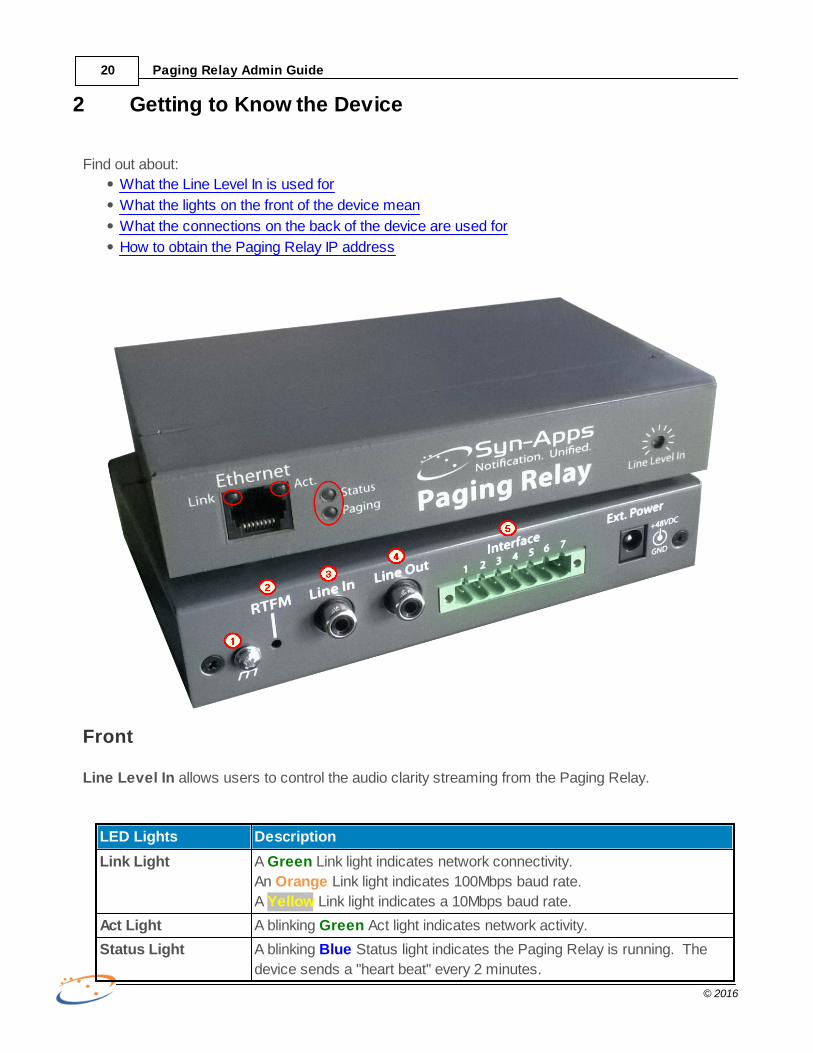
2 Getting to Know the Device
Find out about:
What the Line Level In is used for
What the lights on the front of the device mean
What the connections on the back of the device are used for
How to obtain the Paging Relay IP address
Front
Line Level In allows users to control the audio clarity streaming from the Paging Relay.
LED Lights Description
Link Light A Green Link light indicates network connectivity.
An Orange Link light indicates 100Mbps baud rate.
A Yellow Link light indicates a 10Mbps baud rate.
Act Light A blinking Green Act light indicates network activity.
Status Light A blinking Blue Status light indicates the Paging Relay is running. The
device sends a "heart beat" every 2 minutes.

Getting to Know the Device 21
© 2016
LED Lights Description
Paging Light A Green Paging light indicates the Paging Relay is making a page.
Back
Number Description
1 - Chassis Chassis used for grounding box. If you hear a hum or static in the audio, try
grounding the Paging Relay device.
Connect the earth grounding wire to the Paging Relay device chassis.
2 - RTFM (Reset Test Function Management)
When held briefly, announces the device's IP address. Device must be
connected to a speaker to hear the address.
When held for 15 seconds or longer, resets the device to factory defaults.
3 - Line In Accepts audio in from any standard external audio device. Used for background
music, on-hold music, etc.
4 - Line Out Relays audio from the Line In port. Used to connect to a powered speaker. Mutes
the Line In audio when an active notification is played.
5 - Interface Pins 1 & 2 - Sensor Contact. Used to notify SA-Announce when a contact is
closed. Often connected to buttons, alarms, etc. SA-Announce can be configured
to create a notification upon closure.
Pins 3, 4, & 5 - 600 ohm Audio Output. Used to connect to analog paging
amplifiers.
Pins 6 & 7 - Relay Contact. Used as an on/off switch such as closing doors and
windows or turning on lights.

Paging Relay Admin Guide22
© 2016
Obtaining the Paging Relay IP Address
There are three ways to obtain the Paging Relay IP Address:
Method Description
Line Out Jack Use the Line Out jack on the back of the Paging Relay device to connect to
a powered speaker.
Press the RTFM button briefly. (Note: holding the button for 15 seconds or
longer resets the device to the default settings.)
The IP address broadcasts over the speaker.
DHCP Table If you are using a DHCP server but must use a static IP address:
Plug the Paging Relay device into a DHCP-capable LAN port.
Look up the Paging Relay IP address in the DHCP table using the Paging
Relay device's MAC address located on the bottom of the device.
LAN Connection Log into the switch port and look up the Paging Relay device IP address
using its port number.

Logging Into thePaging Relay
Interface
Part
3

Paging Relay Admin Guide24
© 2016
3 Logging Into the Paging Relay Interface
Enter the Paging Relay IP Address in a browser. See Getting to Know the Device > Obtaining the
Paging Relay IP Address on how to get the address.
Log in with these credentials – admin/admin.
If you are only using the Paging Relay for unicast to multicast streaming, you don't need to make any
configuration changes in the Paging Relay interface.
However, you may want to log into the interface and explore all the features.

UnderstandingUnicast and
Multicast
Part
4

Paging Relay Admin Guide26
© 2016
4 Understanding Unicast and Multicast
There are two common transmission methods used to page registered devices – unicast and
multicast. In a nutshell, unicast transmits duplicate packets of data to the network, one for each
configured endpoint. Multicasting sends only one packet of data to the network, which is then sent
only to interested endpoints by using special IP address assignments. Using multicast to send data
packets is one of the main functions of the Paging Relay device.....although it can do much more.
See the Paging Relay Additional Features section.
Important: If you are using Paging Relay with SA-Announce, multicast must be enabled in SA-
Announce. See SA-Announce Configurations.
Unicast
Unicast is an industry-standard transmission method of sending a packet of data to a single network
destination identified by a unique IP address. Unicast transmission requires no additional network
configuration. Whenever the server receives a packet of data (an audio stream, for example), it then
sends it to each registered device within a notification group. For example, if two phones and one
desktop are in a notification group, then a total of three audio stream packets are transmitted – one
for each endpoint.
Each endpoint must listen to all the packets it receives, checking each packet to see if its device IP
address is contained within the packet. When a device encounters a packet with its address, it grabs
the packet for processing. This can be time consuming and can use a lot of bandwidth. The more
endpoints that are added, the more network bandwidth utilization. At some point, network bandwidth
becomes overloaded, which causes choppy audio over endpoints.
Endpoints are sent the same set of data.
Note: Unicast has also been referred to as point-to-point communication.
Multicast
Multicast sends one data stream to multiple endpoints across the network. This method is more
economical because it optimizes network performance and provides enhanced efficiency by
controlling network traffic and reducing the bandwidth load on network devices. Endpoints on the
network take advantage of network, router, and switch port functionality to decide whether or not to

Understanding Unicast and Multicast 27
© 2016
listen to a multicast IP address, so packets are only sent when asked for by the local switch.
Data is sent to designated endpoints.
Typically, live audio streaming and voice traffic creates heavy bandwidth consumption when sending
via unicast, so multicast is the preferred method. However, multicast is not always available from
ISPs (Internet Service Providers), and often requires specific hardware configuration; both of which
can be costly and time consuming. This is where the Paging Relay comes in. Its patented firmware
converts unicast streams into multicast streams to deliver data streams to endpoints across the
WAN.
One unicast stream is sent from the server to the Paging Relay. The Paging Relay converts the stream to
mulitcast and sends individual streams to the endpoints.
When a notification is triggered, a single unicast stream is sent to each remote Paging Relay device.
The Paging Relay converts this stream into multicast and sends it to the endpoints that have
requested it. The Paging Relay eliminates the need to place a local notification server at remote sites.
It also provides enhanced services. When implemented using a DHCP server utilizing Option 72
WWW server, the Paging Relay devices requires very little technical expertise to implement, and
needs very little configuration. And, it's all at a fraction of the cost of implementing multicast on your
WAN.
Once the Paging Relay device is setup and registered, unicast to multicast is automatic. Now,
instead of phones listening to all data packets to see which apply, each phone only receives data
packets it requests. Note: If multicast is not yet enabled in SA-Announce, the phones won't be able to
receive any data packets.

Paging RelayAdditionalFeatures
Part
5
Paging Relay Additional Features 29
© 2016
5 Paging Relay Additional Features
The Paging Relay device provides many features.
Unicast-to-Multicast – Source multicast audio streams to remote WAN sites.
SA-Announce Integration – Direct integration with SA-Announce allows users to instantly initiate
and distribute SA-Announce notifications from the Paging Relay to selected devices.
Remote Site Failover – Configure the Paging Relay to work with CME or SRST (Survivable Remote
Site Telephony) to provide fault-tolerance in multi-site deployments. SRST direct paging supports
standalone operation to 500 Cisco IP phones. See Direct Paging.
Music on Hold (MoH) – Play music on hold for callers waiting in a call queue or simply placed on
hold.
Background Music – Stream background music to IP and analog speakers. Useful in lobbies,
hallways, retail floors, and more. The Paging Relay can also be paired with SA-Announce to play
background music over IP phones.
Analog Integration – Make use of existing analog PA systems to send pages to phones and
speakers simultaneously. Connect analog PA systems via the 600ohm or Line Out jacks on the
Paging Relay.
Smart Detection & Alerting – Trigger a relay contact closure when an SA-Announce notification
broadcast is sent. The relay contact closure triggers whatever endpoints are connected to the Paging
Relay – close fire doors, lock windows, turn on strobe lights and sirens, etc. Trigger an audio file
stored locally on the Paging Relay through a sensor contact closure, such as a bell tone playing when
a customer crosses your business' entrance. You can also trigger an SA-Announce notification from
the Paging Relay when a sensor contact closes, such as sending an emergency notification to a
specific IP phone when a panic button is pushed.
Night Ringer – Broadcast announcements to overhead speakers to alert personnel of an incoming
call. This is useful in warehouses where staff may not be near the phone or in a garden center where
staff is outside.

Paging Relay Admin Guide30
© 2016
5.1 Remote Site Failover
The Paging Relay supports Cisco Unified Communications Manager Express (CME) and Cisco
Unified Survivable Remote Site Telephony (SRST) for direct device paging for up to 500 Cisco IP
phones. This feature provides true fault-tolerance in the event of system failure. For example, if the
WAN connection between the Paging Relay's physical site and SA-Announce server site goes down,
the SRST single notification group is still operational. When failover is in use, pages initiated at the
remote site are routed from the SRST or CME router directly to the Paging Relay device.
Note: This same setup is used in environments where SA-Announce is not present. See Standalone
Environment for more information.
There are three areas of configuration:
1. Configure router for SRST Mode Session Initiated Protocol (SIP).
2. Configure Paging Relay Interface > SIP Settings and Paging Relay Interface > IP Phones.
3. Configure your phone Call Manager to off-load authentication to the Paging Relay. Important:This requires the phones to be reset. Consider scheduling this change during a maintenance
window.
Router Configuration for SRST Mode SIP Config
Note: The following are general SRST configuration instructions for a Cisco SRST or CME router.
Follow the manufacturer instructions for your router to make the SRST configurations.
Create a SIP trunk that points to the Paging Relay:
Cisco Router SRST
Configuration
Command Line
SRST Commands Command Description
Note: SRST Command configuration is
unique to every customer's environment.
SRST # configure terminal Starts command.
SRST (config) # telephony-service Provide an arbitrary description to
activate the telephony services and
access the telephony services mode.
Our example uses ' telephony-service '.
SRST (config-
telephony) #
dial-peer voice xxxx voip ' xxxx ' denotes the VoIP Dial Voice
Peer.
Note: xxxx can be the Directory Number
(DN) used for the Emergency Alert (EA)
group in SA-Announce.
SRST (config-dial-
peer) #
description Syn-
Apps_Paging_Relay
Provide an arbitrary description for the
device. Our example uses 'Syn-
Apps_Paging_Relay'.

Paging Relay Additional Features 31
© 2016
SRST (config-dial-
peer) #
preference 1 Establishes priority order for DN.
SRST (config-dial-
peer) #
destination-pattern xxxx ' xxxx ' is typically the dial-peer voice
xxxx voip number. This can be the
same number as the most frequently
used SA-Announce notification group
number.
SRST (config-dial-
peer) #
session protocol sipv2 Establishes which SIP protocol to
connect to the Paging Relay, where v2 is
the industry standard.
SRST (config-dial-
peer) #
session target
ipv4:xx.xx.xx.xx
' xx ' denotes the IP address of the
Paging Relay.
(See Obtaining the Paging Relay IP
Address.)
SRST (config-dial-
peer) #
dtmf-relay sip-notify Determines how to deliver the dual-tone
multi-frequency digits.
SRST (config-dial-
peer) #
codec g711ulaw Establishes the audio bandwidth.
g711ulaw is the industry standard in
North America.
SRST (config-dial-
peer) #
no vad Disables VAD (Voice Activity Detection).
This setting is a bandwidth preservation
feature.
SRST (config-dial-
peer) #
end Ends command.
SRST# copy running-config startup-
config (copy run start)
Copies the running config into the start-
up config to make the switch port active.
The screenshot above shows SRST configuration commands.

Paging Relay Admin Guide32
© 2016
Paging Relay Configuration
There are two steps to configuring the Paging Relay for failover:
1. Configure the SIP settings.
2. Configure the IP phones to receive pages during a failover.
Configure SIP Settings1. Navigate to Paging Relay > Device Config > SIP Settings.
2. Check Enable SIP Operation.
3. Configure the following:
Field Default Description
SIP Server 0.0.0.0 Enter the SRST or CME router IP address. This is
the IP address of the SRST or CME router you just
configured.
Remote SIP Port 5060 Default standard SIP port.
Local SIP Port 5060 Default standard SIP port.
Outbound Proxy empty Set if Proxy exists in the environment.
Outbound Proxy Port 0 Set if Proxy exists in the environment.
SIP User ID empty Set to the Directory Number configured when
creating the SIP trunk in the SRST or CME router.
This is the dial-peer voice xxxx voip number
you just configured in the SRST or CME router.
Authenticate ID empty Set to the Directory Number configured when
creating the SIP trunk in the SRST or CME router.
Authentication Password empty Leave empty. Not used at this time.
Re-registration Interval
(in seconds)
360 Adjust as desired.
SIP Multicast Audio
Output Address
230.30.30.
31
This multicast address is used to stream audio to
the desired endpoints (IP phones, IP speakers,
etc.). Typically use the default. If assigning an
address, it must be within the multicast range
224.0.0.0 – 239.255.255.255. Consult your IP
speaker manufacturer documentation to locate the
address for the multicast group section.
SIP Multicast Audio
Output Port
20482 Multicast port used with multicast Output Address.
Typically use the default. If assigning a port
number, it must be even value in the range 20480
– 32768. Consult your IP speaker manufacturer
documentation to locate the port for the multicast
group section.

Paging Relay Additional Features 33
© 2016
Play SIP Calls via Line-
Out
unchecke
d
Check to enable audio play when a page is initiated
through
the Line Out jack, if connected to the Paging
Relay device.
the 600 Ohm connectors, if configured on the
Paging Relay device.
(See Analog / IP Integration to configure these.)
4. Click Save and then click Reboot.
Populate Phones ListFollow the instructions provided in Direct Paging.
Configuration to Off-load Authentication Process to Paging Relay
Next, you must configure the Authentication URL to off-load the authentication process from your
phone system Call Manager to the Paging Relay. If your phone system Call Manager fails over to
SRST mode, the SA-Announce Authentication URL still remains listed in the Call Manager.
Note: The configurations provided below are for a Cisco Unified Call Manager (CUCM) version
10. If you are using an older version of CUCM, the steps may be slightly different. If you are
using a ShoreTel or Avaya Call Manager, please consult your system documentation.
You can configure each phone individually or use the CUCM Bulk Administration.
Set Authentication URL on Individual Phones in CUCM1. Navigate to CUCM > Device > Phone.
2. Search for the specific phone, and then click on the Device Name link to open the
phone's configuration screen.
3. In the External Data Locations Information section, enter the Paging Relay IP address
(for example: http://{PagingRelayIPaddress}/cgi-bin/SAAnnounceLite/authenticate.cgi) in
the Authentication Server and Secure Authentication URL fields.
4. Click Save, and then Apply Config. Note: This may reboot the phone. Verify phone is not
in use prior to clicking Apply Config.

Paging Relay Admin Guide34
© 2016
Set Authentication URL via Bulk Administration in CUCM
Important: This requires the phones to be reset. Consider scheduling this change during a
maintenance window.
1. Navigate to CUCM > Bulk Administration > Phones > Update Phones > Query.
2. Search for desired phones.
3. Click Next.
4. In the Logout/Reset/Restart section, do one of the following:
If all the phones in the search results list are NOT currently in use, click Reset
Phones. All of the phones displayed in the previous search results screen are reset.
If ANY of the phones in the search results list ARE currently in use, click Don't Reset/
Restart phones/Apply Config.
5. In the External Data Locations Information section, enable the following fields and
enter the Paging Relay IP address (for example: http://{PagingRelayIPaddress}/cgi-bin/
SAAnnounceLite/authenticate.cgi):
Authentication Server
Secure Authentication URL

Paging Relay Additional Features 35
© 2016
6. In the Job Information section, do one of the following:
If you chose Reset phones in step 4, click Run Immediately.
If you chose Don't Reset/Restart phones/Apply Config in step 4, click Run Later.
(Don't forget to schedule the job on the Job Scheduler screen. Consult your Call
Manager documentation on how to do this.)
7. Click Submit.
5.1.1 Direct Paging
The Paging Relay supports directly paging up to 500 Cisco IP phones.
Note: The Paging Relay only supports direct paging to Cisco phones at this time.
You can use direct paging in the event of remote site failover, or when you are using the Paging Relay
device without SA-Announce.

Paging Relay Admin Guide36
© 2016
(Optional) Global Settings
You can configure the following settings or simply leave them at their default values.
Global Setting Default Description
Phone Auth UserID Paging
Relay
UserID
Authentication credentials the Paging Relay sends to
the phone. The phone then sends the credentials to
the "Auth URL" asking for permission to listen for the
play audio command. Phone Auth Password Paging
Relay
Password
Redirect URL Blank Typically, the Paging Relay handles authentication.
However, some 3rd-party phone software (such as an
auto attendant software) requires authentication come
from its own software. In this case, enter the software
URL here so authentication is redirected from the
Paging Relay to the 3rd-party software.
Phone Volume 20 Sets the volume for the IP phone speaker or IP
speaker when a page occurs.
Barge in on calls Disabled When enabled, a page to an IP phone interrupts an
active call. Remember this is a global setting. An
active call is interrupted when any page occurs,
whether the page is an emergency or not.
If you need to come back later to populate the Phones section, click Save before leaving this screen.
No need to reboot until after the Phones list is populated.
Populating the Phones List
There are two methods for entering the IP address and Port for each IP phone you want to page to:
manually
fetch the data from either SA-Announce or from a Devices.xml file
Manual Entry1. Navigate to Paging Relay > IP Phones.
2. Manual Config is selected by default. If it isn't, select it.
3. Enter the IP Address and Port in the Phones section for each IP phone you want to direct
page to, and check Active.
4. Click Save and then click Reboot.

Paging Relay Additional Features 37
© 2016
Fetch Data
From SA-Announce
This method requires the use of Syn-Apps' Paging Relay Deploy Tool. This tool looks at all the
SA-Announce groups the Paging Relay is assigned to, and then requests from your Call Manager
the IP addresses for all the phones in the same groups as the Paging Relay. The port number is
already prepopulated to port 80. The tool automatically enables the Active field.

Paging Relay Admin Guide38
© 2016
A request is made daily to SA-Announce and the Call Manager to keep the Paging Relay IP
Phones list up to date. If there are any data changes, the list of phones is updated. So, when you
add the Paging Relay to additional groups, the phones in those groups are automatically added to
the Paging Relay Phones list. Likewise, if you remove the Paging Relay from a group, all the
phones in that group are automatically removed from the Paging Relay Phones list when the next
fetch request is made (unless the phone belongs to a different group that does include the Paging
Relay). If you remove specific phones from the group, but leave the Paging Relay assigned, only
the removed phones are removed from the Paging Relay Phones list.
There are two steps to using this feature:
1. Install the Paging Relay Deploy Tool on the same server as SA-Announce. Contact Syn-
Apps Technical Support from our web site to obtain the tool.
2. Configure the Paging Relay.
Configure Paging Relay
1. Navigate to Paging Relay > IP Phones.
2. Click Fetch Config from SA-Announce.
3. Click Save and then click Reboot.
If there are phones you don't want included during a Paging Relay direct page, uncheck the
Active field for those phones. Important: These phones still receive SA-Announce group
notifications for the groups the phone is assigned to. Inactivating the phone here has no effect
on the SA-Announce group to which it belongs, nor does it inactivate the phone in Call

Paging Relay Additional Features 39
© 2016
Manager.
From Another URL
If you are not using SA-Announce, you can import the IP addresses for the phones from an XML
file. Create a script to pull out the necessary IP phone information. A fetch request is made daily
to the web server where the Device.xml file resides to keep the Paging Relay IP Phones list up to
date.
There are two steps to using this feature:
1. Create the Device.xml file.
2. Configure the Paging Relay.
Create Device.xml
Create the file on a web server.
Use the following format.
Only include the phones you want to direct page to. This could be all your phones, or a
subset.
<?xml version="1.0" encoding="utf-8"?>
<PhoneConfig>
<PhoneList>
<GlobalUserName>SynApps</GlobalUserName>
<GlobalPassword>SynApps</GlobalPassword>
<Phone00Addr>10.10.5.50</Phone00Addr><Phone00Port>80</
Phone00Port><Phone00Active>Yes</Phone00Active><Phone00Type>Cisco</
Phone00Type>
<Phone01Addr>10.10.5.51</Phone01Addr><Phone01Port>80</
Phone01Port><Phone01Active>Yes</Phone01Active><Phone01Type>Cisco</
Phone01Type>
<Phone02Addr>10.10.5.52</Phone02Addr><Phone02Port>80</
Phone02Port><Phone02Active>Yes</Phone02Active><Phone02Type>Cisco</
Phone02Type>
</PhoneList>
</PhoneConfig>
Configure Paging Relay
1. Navigate to Paging Relay > IP Phones.
2. Click Fetch Config from Other URL.
3. Enter the Phone Configure URL. This is the web server IP address and path where
the Device.xml file resides.
4. Click Save and then click Reboot.
If there are phones you don't want included during a Paging Relay direct page and the Phone
list hasn't yet been updated, uncheck the Active field for those phones. You can also use the
Active field to temporarily exclude a phone from direct paging, then reactivate it later, leaving

Paging Relay Admin Guide40
© 2016
the phone in the Device.xml file. Important: Inactivating a phone here does not inactivate it in
Call Manager. It simply excludes the phone from direct paging.
5.2 Music Configuration
The Paging Relay provides the ability to play background music and music on hold at your remote
sites. While you can add an audio file to a router at a remote site, that doesn't allow you to play live
audio. The Paging Relay does.
The Paging Relay accepts audio from any standard external device that can play music. You simply
connect the music device to the Paging Relay's Line In jack. You can stream online radio stations, or
play CDs and MP3s. You can use the same music for background and music on hold (MoH). MoH
and background music are two separate features. You can implement one or the other, or both.
The Paging Relay digitizes the analog signal and transmits it as a multicast stream. You define which
speakers receive background music. You define in your phone system Call Manager which IP
Phones receive background music. Background music can be played on supported IP speakers,
analog PA systems, and IP phones. Our background music functionality includes automatic gating
when played over IP speakers and analog PA systems. That means music is temporarily stopped
when an SA-Announce or SIP notification is broadcasting. When the notification has ended,
background music automatically begins again.
MoH is played when a call is placed on hold or when a call goes into a waiting queue.
These are the basic steps:
1. Connect your external music device to the Paging Relay device.
2. Configure Paging Relay.
3. Want MoH? Configure your phone system Call Manager.
4. Want background music?
over speakers only? Configure SA-Announce and your speakers.
over IP phones only? Configure SA-Announce, your phone system Call Manager, and your
phones.
over speakers and IP phones? Configure SA-Announce, your speakers, your phone system
Call Manager, and your phones.
Important: The following configurations must be done for EACH remote Paging Relay device. If you
have more than one Paging Relay device at the same locale, only one device is configured for music.
Connect Music Device
Connect whatever device you'll use to play music to the back of the Paging Relay device in the
Line In jack using a standard audio coax cable with an RCA plug.

Paging Relay Additional Features 41
© 2016
Configure Paging Relay
Before You Begin: Your phone system Call Manager may require the multicast IP address
entered in step 3 below be in a smaller range than what the Paging Relay allows. Confirm the IP
address range to use in your Call Manager documentation before configuring this feature.
Important: To implement MoH, each remote site Paging Relay device must be configured with
the same Line-in Setting Multicast Address and Multicast Port number in order for MoH to work at
all of your remote sites. This is because you only configure one multicast address and port
number for MoH in Call Managers. Background music is configured as a service in Call Managers
that you then subscribe phones to. MoH is simply a feature that's enabled in your phone template.
Configuration for background music and MoH is basically the same. The only difference is called
out in step 4.
1. Navigate to Paging Relay > Device Config > Line-in Settings section.
2. Check Enable Multicast.
3. (Optional) Enter a Multicast Address and Multicast Port number. Typically, the default
address (230.30.30.30) and port number (20480) are used. If you choose to set these
fields:
Multicast Address range = 224.0.0.0 – 239.255.255.255. (Note: Use an IP address
that is also in an acceptable range per your phone system Call Manager.)
Multicast Port number range = even value between 20480 – 32768.
Choose a unique address and port number, within the designated range, to use.
(Reminder: A unique address and port number is also assigned when configuring
Remote Site Failover, Sensor Contact Closures, and the Night Ringer feature.)
Make note of the IP address and port number. You'll need them when you configure SA-
Announce, your Call Manager, and your IP speakers.
4. Do one of the following:
If you are implementing background music, check Enable Loopback to Line-out.
(loopback = loop through)
If you are implementing MoH only, leave Enable Loopback to Line-out unchecked.
5. (Optional) Check Stop Multicast during Line-In Silence to stop sending multicast packets
when there is no music. If music stops playing, multicast packets continue to be sent. The
silence is simply treated as a blank packet. If there's a chance your music source may get
interrupted and you need to conserve network bandwidth, enabled this feature to stop
multicast when nothing is coming through the Line-In jack. (Note: Typically, this feature is
not used.)
6. Click Save and then Reboot at the bottom of the screen.

Paging Relay Admin Guide42
© 2016
The Paging Relay plays the audio locally and the endpoints listen for the audio at the specified IP
address and port number.
Configure Phones for MoH (Skip this step if you are not using MoH.)
Follow the instructions in Configure Phones for MoH.
Configure SA-Announce, Speakers, Call Manager and IP Phones for
Background Music (Skip these steps if you are not using background music.)
Follow the instructions in Configure SA-Announce, Speakers, & Phones for Background Music.
5.2.1 Configure Phones for MoH
Have you completed the steps in Music Configuration?
There are no configurations needed in SA-Announce if you are only using MoH and not background
music.
Note: The configurations provided below are for CUCM version 10. If you are using an older version
of CUCM, the steps may be slightly different. ShoreTel and Avaya customers, please consult your
Call Manager documentation on how to configure MoH for your system.
In CUCM, there is one default Music on Hold Server. You cannot add a new one. You must edit the
existing default.

Paging Relay Additional Features 43
© 2016
1. Navigate to CUCM > Media Resources > Music on Hold Server.
2. Leave the search parameters 'as is' and click Find.
3. Click the MOH server name.
4. Update the Description to describe what you're configuring.
5. Check Enable Multi-cast Audio Sources on this MOH Server.
6. Enter the following:
Field Input
Base Multi-cast IP
Address
Multicast Address you configured in the Paging Relay.
Base Multi-cast Port
Number
Multicast Port you configured in the Paging Relay.
7. Click Save, and then click Apply Config.

Paging Relay Admin Guide44
© 2016
5.2.2 Configure SA-Announce, Speakers, and Phones forBackground Music
Have you completed the steps in Music Configuration?
There are two basic steps to setting up background music to play over your speakers and/or IP
phones:
1. Configure SA-Announce > Background Music Settings.
2. Configure endpoints to play background music:
over speakers only? Configure SA-Announce and your speakers.
over IP phones only? Configure SA-Announce, your phone system Call Manager, and your
phones.
over speakers and IP phones? Configure SA-Announce, your speakers, your phone system
Call Manager, and your phones.

Paging Relay Additional Features 45
© 2016
SA-Announce
1. Navigate to SA-Announce > Services > Broadcast Services > Background Music
Settings.
2. Enter the following:
Field Input
Music Stream Name Descriptive name of your choice.
Music Stream IP Address Multicast IP Address you configured for the Paging Relay.
Music Stream Port Multicast Port you configured for the Paging Relay.
(Note: The SA-Announce User Guide states the port number
range is 24000-36000. Ignore this range for this setup.)
Important: SA-Announce and Paging Relay IP addresses and port numbers must match.
3. If you plan to play background music over your IP phones, copy the background music
service URL. You'll enter this in your phone system Call Manager. Background music over
speakers only doesn't need this URL.
For ShoreTel customers only: also verify on Services > Broadcast Services > Phone
Services that these three boxes are checked.
Message Browser
Groups Directory
Background Music

Paging Relay Admin Guide46
© 2016
Speakers
Note: If you plan to play background music over IP phones only, skip this section and move on to
Background Music on IP Phones. If you plan to play background music over both speakers and IP
phones, complete this section and the IP Phones section.
IP Speakers
Configuration is slightly different for each brand of IP Speaker. Basically, you need to add the
Multicast Address and Multicast Port you configured in the Paging Relay > Device Config >
Line-in Settings to the IP Speaker so the speaker knows what IP address to listen for.
Configuring IP Speakers provides instructions for Algo, A.N.D., Atlas, and CyberData. If you
have a different brand IP Speaker, consult your speaker documentation for instructions.
Analog Speakers
If you have an existing analog PA system that you plan to play background music over, see
Analog / IP Integration for instructions.
IP Phones
Note: If you plan to play background music over speakers only, skip this section. You only need the
Speakers instructions above. If you plan to play background music over both IP phones and
speakers, complete this section and the Speakers section above.
Call Manager and IP phone configuration is slightly different for each brand of IP phone. See
Background Music on IP Phones for basic steps in configuring background music to play over IP
Phones.

Paging Relay Additional Features 47
© 2016
5.2.2.1 Background Music on IP Phones
Instructions provided here are only the basic steps for configuring your IP phone to play background
music. Refer to your manufacturer documentation for specific instructions. Contact Syn-Apps
Technical Support from our web site if you need assistance.
Basic steps for:
Cisco
ShoreTel
Avaya
Cisco
Note: The configurations provided below are for CUCM version 10. If you are using an older version
of CUCM, the steps may be slightly different.
In CUCM
This is a two-step process:
1. Create a background music phone service.
2. Subscribe the phones you want to play background music on to the background music
service.
Create Background Music Service
1. Navigate to CUCM > Device > Device Settings > Phone Service.
2. Click Add New.
3. Enter the following:
Field Input
Service Name Enter a descriptive name of your choice.
ASCII Service
Name
Enter a descriptive name of your choice. It can be the same as
Service Name.
Service URL Enter the background music service URL from SA-Announce:
http://10.10.4.250/SA-Announce/PhoneServices/
BackgroundMusic.aspx
Service Category Select XML Service
Service Type Select Standard IP Phone Service
4. Check Enable.
5. Click Save.

Paging Relay Admin Guide48
© 2016
Subscribe Individual Phones to Background Music Service
1. Navigate to CUCM > Device > Phone.
2. Search for and select the phone.
3. From the Related Links drop-down list, select Subscribe/Unsubscribe Services, andclick Go.
(Hint: Related Links is in the upper right corner of the CUCM screen.)
A separate, new window opens.
4. From the Select a Service drop-down list, select Background Music.

Paging Relay Additional Features 49
© 2016
5. Click Next.
Window updates.
6. Click Subscribe.
Subscribe Phones to Backgound Music via Bulk Administration
The process for bulk service subscription happens via the template assigned to the phone.
Consult your CUCM documentation on how to use this functionality.
Cisco IP PhonesRemind your end users of how to stop/start background music on their phone when a call is
received.

Paging Relay Admin Guide50
© 2016
ShoreTel
You have two options for configuring background music:
Phone Button Option – Create a phone application and assign it to your ShoreTel phones.
This options allows you to assign background music to a phone button that end users press
to play background music.
Note: The 420 phone does not support this option. All other phone models supported by
SA-Announce do.
Phone Home Screen Option – Edit each phone model's custom configuration file to add
SA-Announce as a trusted server and enter the URL for the browser home page. This
option requires end users to press Mute+Option to access the home screen and then press
the designated key to start background music.
Note: The 655 phone does not support this option. All other phone models supported by
SA-Announce do.
Note: The configurations provided below are for ShoreTel Connect. If you are using ShoreTel
Director, the steps may be slightly different.
Phone Button OptionNote: Use Phone Home Screen Option for 420 phones.
There are two basic steps:
Create a phone application that points to the background music URL.
Assign that phone application to the phones you want to have background music.
Create Phone Application1. In ShoreTel Connect, navigate to Telephones > Phone Applications.
2. Click New.
3. Enter the desired Name and URL in the format http://xx.xx.xx.xx/SA-Announce/PhoneServices/PhoneServices.aspx
where xx.xx.xx.xx is the SA-Announce server IP address.
4. Click Save.

Paging Relay Additional Features 51
© 2016
Assign Phone Application1. Navigate to Users > Programmable Buttons.
2. Select a user's phone.
3. On the IP Phones tab, configure an available line as follows:
Select Telephony from the # drop-down list.
Select Phone Application from the b drop-down list. (This selection causes the Target
drop-down list to display.)
Enter a descriptive Long Label and a Short Label.
Select the phone application you created from the Target drop-down list.
4. Click Save.
Repeat these steps for each user's IP phone for which you want background music available.

Paging Relay Admin Guide52
© 2016
Verify Background Music on Phones1. Press the Background Music Application button.
2. Press the Background Music option to start playing music; press again to stop playing
music.
Phone Home Screen OptionNote: Use Phone Button Option for 655 phones.
1. On the ShoreTel Connect/Director server, navigate to the appropriate c:\inetpub\ftproot in
Windows Explorer.
400 series phones are located in c:\inetput\ftproot\phoneconfig
all other phones are lociated in c:\inetput\ftproot
ShoreTel IP Phones Custom File Name
265 s36custom.txt
420 custom_IP420.txt
480 custom_IP480.txt
480g custom_IP480g.txt
485g custom_IP485g.txt
560 s6custom.txt
560g s6gcustom.txt
565g s6ccustom.txt
2. Edit the two entries below, where xx.xx.xx.xx is the SA-Announce server IP address:
Trusted Servers xx.xx.xx.xx
BrowserHome http://xx.xx.xx.xx/SA-Announce/PhoneServices/PhoneServices.aspx
3. Save the files.
4. Reboot the phones.
Verify Background Music on Phones1. Press the Mute and Options buttons within two seconds of each other.
2. Press the number key associated to background music.
3. Press the Stop soft key or speaker button to stop the background music.
4. Press the Exit soft key to exit the menu.
Note: If you press Exit before stopping the background music, the background music
continues to play.
Press the speaker button to disconnect from the background music.
Avaya Consult your Avaya Call Manager documentation for how to set up background music service.
Remind your end users of how to stop/start background music on their phone when a call is
received.

Paging Relay Additional Features 53
© 2016
5.3 Contact Closures
The Paging Relay has two different types of contact closure connections.
Relay Contact Closure – Used to send a trigger from an SA-Announce Emergency Alert group
to the Paging Relay to close doors and windows, and turn on lights and sirens.
Use Cases
A fire emergency alert is sent, the Paging Relay sends a trigger to close fire doors, turn
on strobe lights, and activate a siren.
Activate a siren for an emergency weather alert.
Sensor Contact Closure – Used to trigger the Paging Relay to play an audio file when an
external switch closes its connection. Can also trigger SA-Announce to send a notification.
Use Cases
A customer comes through the door of your business, a tone plays overhead to alert
staff that a customer is in the building.
A patient wanders into a nursing home hallway late at night. Front desk personnel are
notified.
An employee or student on campus pushes a panic button. Security staff is alerted.
A customer pushes a help button. Notification is sent to the department manager that a
customer is waiting for assistance.
In a nutshell,
Relay contact closures go from SA-Announce > Paging Relay > endpoints.
Sensor contact closures start at endpoints > Paging Relay > (optionally) SA-Announce.
5.3.1 Relay Contact Closure Configuration
The Paging Relay can be configured to send a contact closure signal that can activate any electrical
device that reacts with a simple ‘on switch’. For example, when an Emergency Alert notification is
sent from SA-Announce, the audio can trigger the Paging Relay to send a signal to close fire doors,
lock windows, and turn on strobe lights and sirens.
Endpoints are connected to a bank of relays, one of which is connected to the Paging Relay device.
The SA-Announce notification group tells the Paging Relay device to send a contact closure trigger,
which then propagates through the bank of relays, turning on the endpoints.

Paging Relay Admin Guide54
© 2016
Non-emergency use cases might be:
in a warehouse, lights are turned on to alert staff that they need to pay attention to a notification
being played over the phones.
for integrations with PA systems that require a contact closure to know audio is being sent on aparticular interface and they should play it.
There are three basic steps:
1. Connect the electrical devices to be closed or turned on to one of more connected relays.
2. Connect one of the relays to the Paging Relay device.
3. Configure the appropriate SA-Announce notification groups.
Connect to the Paging Relay
The endpoints to be triggered (doors, windows, lights, sirens, etc.) each have some sort of
electronic settings. These electronic settings are connected to one or more relays throughout the
building. The relays are all connected together, and one of those relays connects to Pins 6 & 7 in
the back of the Paging Relay device.
Important: Consult the manufacturer documentation for the proper amperage and VDC for
the endpoints you are connecting to the Paging Relay. Connecting them improperly can
damage the Paging Relay device.
An open state means the switch is open, which means the relay action is off. When the switch isclosed, the relay action is on.
For example:

Paging Relay Additional Features 55
© 2016
Normal state:
Endpoint Normal State Switch Relay Action
Doors Open
Open OffWindows Unlocked
Lights Off
Sirens Off
Emergency Alert notification sent:
Endpoint Emergency State Switch Relay Action
Doors Closed
Closed OnWindows Locked
Lights On
Sirens On

Paging Relay Admin Guide56
© 2016
All Clear notification sent to return to normal state:
Endpoint Normal State Switch Relay Action
Doors Open
Open OffWindows Unlocked
Lights Off
Sirens Off
Relay Action is set in the SA-Announce notification group.
Paging Relay Configuration
Typically, there is no configuration for the Paging Relay. Contact closure is configured at the
notification group level in SA-Announce. This provides more control over the circumstance in
which a contact closure is triggered.
There is a Relay Settings section in the Paging Relay interface > Device Config screen:
However, be aware that when enabled, the settings here are global and override the SA-Announce
notification group settings that this Paging Relay is associated with. Therefore, typically, the Relay
Settings here are left disabled. The Relay Settings here are used for those customers who have
a high-end model analog audio amplifier that requires an on switch in order to turn on the input
port. (Note: Most amplifiers do not have this requirement.) See Analog / IP Integration.
Configure SA-Announce
In an emergency situation, there will be an initial alert notification that plays an audio for the
emergency situation at hand and turns the contact closures on (which triggers closing doors,
locking windows, etc.). A second "all clear" notification is sent when the emergency is over, which
turns the contact closures back off.
Turn Contact Closures On1. Navigate to SA-Announce > Groups > Create/Edit Groups > Paging Relays.
2. From the Select Group to Edit drop-down list, select the appropriate SA-Announce
group.
3. Do one of the following:
If the Paging Relay device is in the Selected column, click on it.
If the Paging Relay device is in the Available column, click on it and click to
move it to the Selected column.
4. From the Relay Action drop-down list, select On.

Paging Relay Additional Features 57
© 2016
5. Do one of the following:
For emergency scenarios, leave the On Seconds field blank. This allows the relay
action to remain on until a second "all clear" notification is sent to turn them off.
For non-emergency scenarios, such as turning on a light to alert staff that they need to
pay attention to a notification, enter the number of seconds the relay is to remain on.
This action automatically sets the relay action back to off at the end of the time period
specified so a second notification to turn the relay action off is not necessary.
6. Click Set Options.
Turn Contact Closures Back Off1. Navigate to SA-Announce > Groups > Create/Edit Groups > Paging Relays.
2. From the Select Group to Edit drop-down list, select the appropriate Emergency Alert
"all clear" group.
3. Do one of the following:
If the Paging Relay device you configured above is in the Selected column, click on it.
If the Paging Relay device you configured above is in the Available column, click on it
and click to move it to the Selected column.
4. From the Relay Action drop-down list, select Off.
5. Leave the On Seconds field blank.
6. Click Set Options.

Paging Relay Admin Guide58
© 2016
5.3.2 Sensor Contact Closures Use Cases
You can configure the Paging Relay to play a locally stored audio file, an SA-Announce notification, or
play both a local audio file and a notification when triggered by a sensor. For example, when you walk
through the door at a store, an infrared sensor is triggered that causes a tone to play on an overhead
analog speaker system. This tone comes from an audio file stored on the Paging Relay device. No
SA-Announce configuration is required.
We highly recommend reading through the use cases provided here first, so you have an
understanding of what to configure.
Note: Already familiar with use cases and configuration? Jump to the Sensor Contact Closure
Configuration topic.
Sensor Contact Closure Use Cases
Sensor configuration varies depending on the use case. Here are few scenarios to get you started.
Scenario 1: Someone comes through the door of your business, a tone plays over analog
overhead speakers to alert staff that a customer is in the building.
1. You'll have some sort of motion detector that detects when someone has crossed the
entrance threshold.
2. Connect your analog speakers to your paging amplifier, which is then connected to the
Paging Relay device using the Line Out jack or 600 Ohm connectors. (See Analog / IP
Integration.)
3. Connect the motion detector to the Paging Relay device using Pins 1 & 2. (See Sensor
Contact Closure Configuration.)
4. Enable Play Audio Locally. (See Sensor Contact Closure Configuration.)
5. Upload the audio file the Paging Relay will play. (See Sensor Contact Closure
Configuration.)
Note: Sensor Multicast Audio Address and Sensor Multicast Audio Port are prepopulated by
default. Because scenario 1 uses an analog speaker, these settings are not used and are
ignored.
Threshold is crossed.
Motion detector detects movement through doorway, which closes Pins 1 & 2 on the
Paging Relay device.
When Pins 1 & 2 are closed, Paging Relay's local Sensor Triggered audio file plays over
the analog overhead speaker.

Paging Relay Additional Features 59
© 2016
If your business has more than one entrance and you want a tone to play over all of them, you
could:
1. Connect the motion detectors and speakers together using a bank of relays. Connect
one of those relays to the Paging Relay device. The same audio file is played any time
any of the configured entrances are crossed.
2. Use a Paging Relay device for each entrance so that each one has its own tone to let
staff know which entrance the customer came through.
Scenario 2: A patient wanders into a nursing home hallway late at night. A notification is played
over an IP speaker at the front desk.
1. You'll have some sort of motion detector that detects when someone is in the hallway.
2. Connect the motion detector to the Paging Relay device using Pins 1 & 2. (See Sensor
Contact Closure Configuration.)
3. Enable Play Audio via Multicast. (See Sensor Contact Closure Configuration.)
4. Enter a multicast IP address and port number for the IP speaker to listen for. (See Sensor
Contact Closure Configuration.)
5. Upload the audio file the Paging Relay will play. (See Sensor Contact Closure
Configuration.)

Paging Relay Admin Guide60
© 2016
6. Configure the IP speaker to listen to the multicast IP address and port number configured.
Motion detector detects movement in hallway, which closes Pins 1 & 2 on Paging Relay
device.
When Paging Relay device Pins 1 & 2 are closed, local Sensor Triggered audio file plays a
message on an overhead IP speaker at the Front Desk.
Scenario 3: A customer pushes a help button. Notification is sent to the department manager
that a customer is waiting for assistance.
1. Connect help button to Pins 1 & 2 on the Paging Relay device. (See Sensor Contact
Closure Configuration.)
2. Add the Paging Relay and department manager phone to the SA-Announce Emergency
Alert group that will send the notification alert. (See Sensor Contact Closure Configuration.)
3. In SA-Announce > Settings > IP Endpoint Setup, set the GP Input 0 > Activate: to the group
the Paging Relay was added to in step 2 above. (See Sensor Contact Closure
Configuration.)

Paging Relay Additional Features 61
© 2016
Help button is pressed, which closes Pins 1 & 2 on the Paging Relay device.
When Paging Relay device Pins 1 & 2 are closed, SA-Announce picks up the request,
which triggers a notification to the department manager's phone.
Notes: In Scenario 3, neither Play Audio Locally nor Play Audio via Multicast are enabled.
Sensor Multicast Audio Address and Sensor Multicast Audio Port are prepopulated by
default. Since a speaker is not used in this scenario, these settings are not needed and are
ignored.
A Paging Relay device is needed for each help button in order to know the location, so
personnel know which department to go to.
Scenario 4 – Sensor and Relay Contact Closures Combined: An employee or student
on campus pushes a panic button. Security staff is notified and a strobe light is turned on.
1. Connect the panic button to Pins 1 & 2 on the Paging Relay device. (See Sensor Contact
Closure Configuration.)
2. Connect the strobe light to Pins 6 & 7 on the Paging Relay device. (See Relay Contact
Closure Configuration.)
3. Add the Paging Relay to the SA-Announce Emergency Alert group that will turn on the
strobe light. (See Relay Contact Closure Configuration.)
4. Add the Paging Relay and Security desk phone to the SA-Announce Emergency Alert group
that will send the notification to the Security desk phone. (See Sensor Contact Closure
Configuration.)
5. In SA-Announce > Settings > IP Endpoint Setup, set the GP Input 0 > Activate to the group
the Paging Relay was added to in step 3 above. (See Sensor Contact Closure

Paging Relay Admin Guide62
© 2016
Configuration.)
Panic button is pressed, which closes Pins 1 & 2 on the Paging Relay device.
When Paging Relay device Pins 1 & 2 are closed, SA-Announce picks up the request,
which triggers an Emergency Alert notification to the specified Security desk phone and
closes Pins 6 & 7 on the Paging Relay device.
When Paging Relay device Pins 6 & 7 are closed, the strobe light is on.
Notes: In Scenario 4, neither Play Audio Locally nor Play Audio via Multicast are enabled.
Sensor Multicast Audio Address and Sensor Multicast Audio Port are prepopulated by
default. Since a speaker is not used in this scenario, these settings are not needed and are
ignored.
A Paging Relay device is needed for each panic button in order to know the location, so
security officers know where to go.
5.3.2.1 Sensor Contact Closure Configurations
These are the basic steps:
1. Connect the electrical devices to the Paging Relay device that will send the trigger.
2. Configure Sensor Triggered Settings in the Paging Relay interface.
3. Connect speakers, if needed, to the Paging Relay device.
4. Configure where the audio file will come from:
Upload an audio file to the Paging Relay device.
Configure SA-Announce to send a notification.

Paging Relay Additional Features 63
© 2016
Connecting to the Paging Relay
The endpoint sensor (infrared light, motion detector, help button, etc.) is connected to Pins 1 & 2
on the back of the Paging Relay. If more than one endpoint sensor is needed, connect them
through a bank of relays. Connect one of those relays to the Paging Relay. Note: Whether you
can connect multiple endpoint sensors depends on the sensor contact closure use case. See
Sensor Contact Closures Use Cases.
Important: Pins 1 and 2 are dry, meaning there can be no current supplied from a device
connected to them.
The normal state of Pins 1 & 2 are open. When an external sensor closes the switch, a trigger is
sent to close Pins 1 & 2, which triggers a Paging Relay function, such as playing a local audio file
on an overhead speaker.
Configuring the Sensor TriggersNote: How you configure the Sensor Triggered Settings depends on the sensor contact closure use
case. See Sensor Contact Closure Use Cases
1. Navigate to Paging Relay > Sensor.
2. Check Play Audio Locally to play audio over an analog speaker. Plays the audio file stored
locally on the Paging Relay device over an analog speaker.
3. Check Play Audio via Multicast to play audio over IP speakers. Plays the audio file stored
locally on the Paging Relay device over an IP speaker.
4. (Optional) Enter a different unique multicast IP address and port number for the IP speaker to
listen for. Typically, the default address (230.30.30.32) and port number (20484) are used.
If you choose to set these fields:
Sensor Multicast Audio Address. Range = 224.0.0.0 – 239.255.255.255. (Note: Use an IP
address that is also in an acceptable range per your phone system Call Manager.)
Sensor Multicast Port number. Range = even value between 20480 – 32768.
You choose a unique address and port number, within the designated range, to use.
(Reminder: A unique address and port number is also assigned when configuring Remote
Site Failover, Background Music, MoH, and Night Ringer features.)
Make note of the IP address and port number. You'll need them to configure IP speakers.

Paging Relay Admin Guide64
© 2016
5. Click Save and then Reboot at the bottom of the screen.
When a sensor is triggered, an HTTP request is sent to a Web handler. The sensor Web handler
in SA-Announce is always listening for HTTP requests. If the Paging relay belongs to a notification
group, SA-Announce sends that notification to the endpoint(s) connected to the Paging Relay.
Upload Audio FileNote: If your sensor contact closure use case only includes playing an SA-Announce notification,
skip this step. Whether or not you need this step depends on the sensor contact closure use case.
See Sensor Contact Closure Use Cases.
Audio file specifications:
File Type = RIFF (little endian) data, WAV audio, or Microsoft PCM
Parameters = 16 bit resolution, mono, 8000Hz sampling frequency
1. Navigate to Paging Relay > Audio Files.
2. Scroll down to Sensor Triggered.
3. Click Choose File and select audio file to upload for the Paging Relay to use.
4. Click Save.
Paging Relay Additional Features 65
© 2016
Speakers
IP Speakers
Configuration is slightly different for each brand of IP Speaker. Basically, you need to add the
Sensor Multicast Audio Address and Sensor Multicast Audio Port you configured in the Paging
Relay > Device Config > Sensor Trigger Settings to the IP Speaker so the speaker knows
what IP address to listen for.
Configuring IP Speakers provides instructions for Algo, A.N.D., Atlas, and CyberData. If you
have a different brand of IP Speaker, consult your speaker documentation for instructions.
Analog Speakers
If you have an existing analog PA system that you plan to play background music over, see
Analog / IP Integration for instructions.
Configure SA-Announce
Note: If your sensor contact closure use case only includes playing a local audio file, skip this step.
Whether or not you need this step depends on the sensor contact closure use case. See Sensor
Contact Closure Use Cases.
Add to Notification GroupAdd the Paging Relay to the SA-Announce Emergency Alert notification group that will send the
audio file for the sensor triggered. This may be an existing group or you may need to create a new
group. See SA-Announce Configurations > Add to Notification Groups. Important: The Group
Type must be Emergency Alert in order to utilize the GPIO functionality that you must set in the
next step below.
Set GPIO to Activate Notification Group1. Navigate to Settings > IP Endpoint Setup.
2. From the GP Input 0 > Activate drop-down list, select the notification group you just added
the Paging Relay to.
Settings are automatically saved.

Paging Relay Admin Guide66
© 2016
5.4 Night Ringer Configuration
The Paging Relay can be configured to send a loud tone to an outside or overhead speaker to alert
staff that another line is being called.
Use CasesLarge warehouses where staff may not be close enough to hear the phone ring.
Outside areas where staff may not be near the phone, such as garden centers.
After hours when staff may be working in a back room.
Phone line and Nightringer line are both configured in your Call Manager to share the same line.
Paging Relay has Nightringer enabled and is configured with the shared line number.
Customer calls primary line, which rings Nightringer line at the same time.
When the Paging Relay receives the Nightringer line call, it plays its locally stored Night
Ring audio file over the speaker connected to the Paging Relay device.

Paging Relay Additional Features 67
© 2016
These are the basic steps:
1. Configure your Call Manager to share the primary line with a Nightringer line.
2. Configure Nightringer Settings in the Paging Relay interface.
3. Upload your own Night Ring audio file, if desired, or you can just use the default.
4. Configure the outdoor or overhead speaker to the Paging Relay device.
Configure Call Manager
Configure the Paging Relay device as a 3rd-party SIP device in your phone system Call Manager.
For CUCM, refer to the CyberData article for details. (Note: this document is for older CUCM
versions, but the steps are basically the same for the new versions as well.) ShoreTel and Avaya
customers, please consult your Call Manager documentation.
Note: If you are utilizing both the Remote Site Failover (SIP Settings configuration) and
Nightringer Paging Relay features, use the Advanced SIP phone configuration in your Call
Manager so that multiple lines can be configured.
Configure Nightringer Settings
1. Navigate to Paging Relay > Device Config > Nightringer Settings section.
2. Check Enable Nightringer.
3. Configure the following:
Nightringer
SettingsDefault Details
This section configures the Paging Relay to listen for the second phone line.
SIP Server 0.0.0.0 Add the SIP Server address xx.xx.xx.xx. SIP server is your
Call Manager.
Remote SIP Port 5060 Typically left at default. 5060 is the default Remote SIP Port.
Limited to five characters.
Note: This is the same Port number assigned during the
Remote Site Failover configuration.
Local SIP Port 5062 Typically left at default. 5062 is the Local SIP standard port.
Limited to five characters ranging from 2000 to 65535.
Important: This must be a unique Port number from the one
assigned during the Remote Site Failover configuration.
Outbound Proxy empty Set if Outbound Proxy exists in the environment. When
present, it is commonly a numeric IP address in dotted
decimal notations or the Fully Qualified Domain Name FQDN).
Limited to 255 characters
Outbound Proxy
Port
0 Set if Outbound Proxy Port exists in the environment. Limited
to 5 characters ranging from 1 to 65535.
User ID empty Limited to 64 alphanumeric characters. This is the shared
phone line.
Authenticate ID empty Limited to 64 alphanumeric characters. This is your Call

Paging Relay Admin Guide68
© 2016
Nightringer
SettingsDefault Details
Manager User ID.
Authenticate
Password
empty Limited to 64 alphanumeric characters. This is the password
associated with your Call Manager User ID.
Re-Registration
Interval (in sec.)
360 Set as desired.
This section configures what the Paging Relay does when it gets a call.
Nightringer
Multicast Audio
Output Address
230.40.40.
41
Typically the default value is used. If you choose to set this
field, enter a unique multicast IP address in the range of
224.0.0.0 – 239.255.255.255.
Note: Use an IP address that is also in an acceptable range
per your phone system Call Manager.
Nightringer
Multicast Audio
Output Port
21482 Typically the default value is used. If you choose to set this
field, enter a unique port number that is an even value between
20480 – 32768.
Reminder: A unique address and port number is also
assigned when configuring Remote Site Failover, Background
Music, MoH, and Sensor Contact Closure features.
Play Nightringer
via Line-Out
unchecke
d
Check if you are using your existing analog PA system.
Upload Audio File
Audio file specifications:
File Type = RIFF (little endian) data, WAVE audio, or Microsoft PCM
Parameters = 16 bit resolution, mono, 8000Hz sampling frequency
1. Navigate to Paging Relay > Audio Files.
2. Scroll down to Night Ring.
3. Click Choose File an select audio file to upload for the Paging Relay to use.
4. Click Save.

Paging Relay Additional Features 69
© 2016
Configure Speakers
IP Speakers
Configuration is slightly different for each brand of IP Speaker. Basically, you need to add the
Nightringer Multicast Audio Output Address and Nightringer Multicast Audio Output Port you
configured in the Paging Relay > Device Config > Nightringer Settings to the IP Speaker so
the speaker knows what IP address to listen for.
Configuring IP Speakers provides instructions for Algo, A.N.D., Atlas, and CyberData. If you
have a different brand IP Speaker, consult your speaker documentation for instructions.
Analog Speakers
If you have an existing analog PA system that you plan to play background music over, see
Analog / IP Integration for instructions.
5.5 Configuring IP Speakers
IP Speakers can be used:
to play background music
in conjunction with sensor contact closures
in conjunction with the night ringer feature
for direct paging
Note: The following instructions are for speakers running Syn-Apps firmware. If your IP speaker is
not covered below, consult the manufacturer documentation on how to configure multicast in your
speaker.
Which speaker are you configuring?
Advanced Network Devices (A.N.D.)
Algo
Atlas
CyberData
Advanced Network Devices (A.N.D.)
1. Launch a browser, navigate to http://xx.xx.xx.xx where xx.xx.xx.xx is the speaker IP
address, and log in to the speaker user interface.
2. Click Device Settings, and then click Misc.
3. In the Permanent Streams section, set the Priority, Latency, Volume, and Audio Channel
as desired.
4. Enter the IP:Port = Multicast Address:Multicast Port you configured for the Paging Relay >
Device Config > Line-in Settings. For example: 239.5.5.5:20480.
5. (Optional) Enter a Source IP as desired, or leave blank.

Paging Relay Admin Guide70
© 2016
6. Click Save Permanent Stream Changes at the bottom of the screen.
Algo
1. Launch a browser, navigate to http://xx.xx.xx.xx where xx.xx.xx.xx is the speaker IP
address, and log in to the speaker user interface.
2. Click Basic Settings, and then click Multicast.
3. In the Multicast Mode section, click Slave/Receiver.
4. In the Multicast Slave/Receiver Settings section, check the desired zones.
5. In the Zone Definition section, enter the IP:Port for the zone you selected where IP:Port =
Multicast Address:Multicast Port you configured for the Paging Relay > Device Config >
Line-in Settings. For example: 239.5.5.5:20480.
6. Click Save at the bottom of the screen.
Atlas Although the Atlas user interface has a settings screen, there are some known issues with it.
Therefore, Atlas speakers must be configured in an XML file.
Note: If you are using the Paging Relay in a standalone environment (without SA-Announce), use
the Atlas IP Speaker in Standalone Environment instructions instead.
1. Create a virtual directory on your web server called ipspeaker and point it to where the
IPSpeaker.xml file resides on the SA-Announce server – C:\Program Files (x86)\Syn-Apps
\SA-Announce.
2. Open the IPSpeaker.xml file on the SA-Announce server.
3. Append the following element:
<IPSpeakerConfiguration>
<PermanentStreams>
<Channel stream="230.90.90.90"
port="21000" priority="99" volume="4" />
</PermanentStreams>
</IPSpeakerConfiguration>
Attribute Values
Channel
stream
The Multicast Address you configured for the Paging Relay > Device Config
> Line-in Settings.
port The Multicast Port you configured for the Paging Relay > Device Config >
Line-in Settings.
priority Set a priority between 1-100. 1 is the highest priority.
volume Set a volume between 1-13. 13 is the loudest.
4. Save the file.
5. Reboot the speaker.

Paging Relay Additional Features 71
© 2016
You should now see the permanent file setting listed on the Speaker Status screen in the
multicast streams section.
CyberDataOptional: You may want to update your speaker firmware to the most current Syn-Apps version
before beginning. See Update IP Speaker Firmware for instructions on updating the IP Speaker
firmware.
1. Launch a browser, navigate to http://xx.xx.xx.xx where xx.xx.xx.xx is the speaker IP
address, and log in to the speaker user interface.
Login credentials:
Username = admin
Password = admin
2. Click Multicast Config.
3. Check Enable Multicast Operation.
4. Enter the following:
Address = Device Config > Line-in Settings > Multicast Address you configured for the
Paging Relay.
Port = Device Config > Line-in Settings > Multicast Port you configured for the Paging
Relay.

Paging Relay Admin Guide72
© 2016
Multicast Group Name = Descriptive name of your choice.
5. Click Save and then Reboot.
5.5.1 Atlas IP Speaker in Standalone Environment
Note: If you are using the Paging Relay with SA-Announce, use the Configuring IP Speakers > Atlas
instructions instead.
1. Create an XML file here – http://{WebServerIPaddress}/ipspeaker/IPSpeaker.xml – with the
following element:
<IPSpeakerConfiguration>
<PermanentStreams>
<Channel stream="230.90.90.90"
port="21000" priority="99" volume="4" />
</PermanentStreams>
</IPSpeakerConfiguration>
Attribute Value
Channel
stream
The Multicast Address you configured for the Paging Relay > Device Config >
Line-in Settings.
port The Multicast Port you configured for the Paging Relay > Device Config > Line-
in Settings.
priority Set a priority between 1-100. 1 is the highest priority.
volume Set a volume between 1-13. 13 is the loudest.
Note: On a windows web server, the XML file can be moved to: C:\intpub\wwwroot\ipspeaker
\IPSeaker.xml.
2. Save the file.
3. Reboot the speaker.
4. Verify on the Speaker Configuration screen that the file is being retrieved.

Paging Relay Additional Features 73
© 2016
You should now see the permanent file setting listed on the Speaker Status screen in the multicast
streams section.

Paging Relay Admin Guide74
© 2016
5.6 Analog / IP Integration
The Paging Relay can integrate with your existing analog PA system, or be used with a temporary PA
system to broadcast announcements at an event.
Uses CasesAllows SA-Announce to utilize the speakers during a notification so the page can
simultaneously go across phones and speakers.
Allows the Paging Relay to utilize the speakers in the event WAN connection to SA-
Announce is down, if your Paging Relay is set up for failover. See Remote Site Failover.
Paging Relay connected to outdoor speakers can broadcast announcements at a
marathon, street fair, or outdoor concert.
Note: Analog integration works with single-zone paging only. If your company requires multi-zone
paging, contact Syn-Apps Technical Support from our web site.

Paging Relay Additional Features 75
© 2016
There are three basic steps:
1. Connect the Paging Relay and Paging Amplifier devices to each other.
2. Configure Paging Relay.
3. Configure SA-Announce.
Connect Paging Relay and Paging Amplifier
There are two methods for connecting your existing PA systems with a Paging Relay device in that
location.
utilizing the 600 ohm connectors
utilizing the Line Out jack
600 ohm Connector
The 600 ohm connectors provide balanced professional quality output. Some analog audio
amplifiers use the 600 ohm Audio Output connection method exclusively; while others provide
both the 600 ohm connector and RCA-style line out connectors.
Connect the 600 ohm cable from the audio amplifier to the back of the Paging Relay device.

Paging Relay Admin Guide76
© 2016
Note: If you have a high-end model analog audio amplifier that requires an on switch in order
to turn on the input port, do the following addition steps.
1. Connect the audio amplifier Fault Sense Input (Common) to Pin 1 and Fault Sense
(Sense) to Pin 2 in the back of the Paging Relay Device.
2. Configure the Paging Relay > Device Config > Relay Settings section:
Check Close Relay During Notification Audio.
If you are playing background music over your speakers, check Close Relay During
Line-in/Line-out Loopback.
These Paging Relay settings are global, meaning they override any Relay Action settings
configured for the SA-Announce notification groups this Paging Relay is associated with. If
you are also implementing contact and/or sensor closures, we highly recommend contacting
Syn-Apps Technical Support to understand how enabling Relay Settings in the Paging Relay
will affect Relay Action settings in the SA-Announce notification groups.
Line Out Integration
To integrate an analog overhead system that does not contain a 600 ohm connector with thePaging Relay, the Line Out jack on the back of the Paging Relay device is utilized. Thismethod provides a quick and easy setup option valid for a single zone configuration.

Paging Relay Additional Features 77
© 2016
Plug one end of an RCA coax cable into the Line Out jack on the back of the Paging Relay and
the other end into an RCA Line In jack on the analog audio amplifier. This connection provides
an Hi-Z or 10k ohm standard / unbalanced audio signal to the amplifier.
Paging Relay Configuration
Note: If you configured the Paging Relay to play background music, you've already completed this
step as part of Music Configuration.
1. Navigate to Paging Relay > Device Config > Line-in Settings section.
2. Check Enable Loopback to Line-out.
3. Click Save at the bottom of the screen.
SA-Announce Configurations
Note: If you are configuring a feature that does not require an SA-Announce notification, skip this
section. For example, if you are configuring the Paging Relay to play a tone when a customer walks
through the door of your business, that can be done with just the Paging Relay. See Sensor Contact
Closure Configuration for more info. Another scenario is using the Paging Relay for live audio paging
Paging Relay Admin Guide78
© 2016
directly to IP phones and speakers.
There are three basic steps:
1. Add your analog speakers to the appropriate External notification groups. Follow the
instructions in the SA-Announce User Guide > Notification Group Configuration > External
section.
2. Create External Dialers. Follow the instructions in the SA-Announce User Guide > External
Phone Integration section.
3. If you did not already enable Line Out when you added the Paging Relay to the SA-Announce
group(s) when you initially setup the Paging Relay device, you'll need to go back and do this
now. See SA-Announce Configurations in this guide.
5.7 Standalone Environment
SA-Announce Lite is embedded in the Paging Relay firmware, therefore standard SA-Announce
licensing applies. Please contact [email protected] for more information.
There are two standalone environments:
Paging Relay without SA-Announce but with Call Manager
Paging Relay alone, without Call Manager or SA-Announce
Paging Relay without SA-Announce
The Paging Relay can be used with your Call Manager without SA-Announce being present. In this
scenario, you use direct paging to your Cisco IP phones instead of relying on notifications from SA-
Announce. Most of the Paging Relay features are available without SA-Announce.
Music on Hold (MoH) - The Paging Relay device simply provides the method for making the
music available. The Call Manager sends the command to the phone to actually play the music.
Background Music - Background music can be configured to play over speakers, but not IP
phones. SA-Announce is required to utilize the background music service created in your Call
Manager.
Analog / IP Integration - Use your existing PA system to play background music, for direct
paging, to play an audio file stored on the Paging Relay device to overhead speakers (sensor
contact closure and night ringer features).
Relay Contact Closures - Using this feature without SA-Announce requires using our Paging
Relay API to send the relay action. Contact Syn-Apps Technical Support from our web site for
more information.
Sensor Contact Closures - There are many use case scenarios that don't incorporate an SA-
Announce notification. For example, play an audio file, stored on the Paging Relay, when a
customer enters your business.
Direct Paging - You can directly page up to 500 Cisco IP phones. To set up Direct Paging, you
need to do one of the following:
o Go through an SRST or CME router. Follow the steps for Remote Site Failover.

Paging Relay Additional Features 79
© 2016
o Register the Paging Relay directly to your Call Manager. Follow the steps for Direct Call
Manager Registration.
Night Ringer - Play an audio file, stored on the Paging Relay device, on an overhead IP and/or
analog speakers to notify staff that a caller is on the line.
Paging Relay Alone
The Paging Relay can still be used even if you don't have a Call Manager or SA-Announce.
You can:
page to IP speakers and analog PA speakers using SIP Peer-to-Peer dialing to the Paging
Relay. Contact Syn-Apps Technical Support from our web site for more information.
play background music over speakers. Follow the Play Background Music Over Speakers
instructions.
play an audio file over speakers, triggered by a sensor contact closure. See Play Audio File on
Sensor Contact Closure for more information.
use the Paging Relay API to store and play audio files. Contact Syn-Apps Technical Supportfrom our web site for more information.
5.7.1 Direct Call Manager Registration
To use Direct Paging, there are three areas of configuration:
1. Directly register the Paging Relay with your Call Manager.
2. Configure Paging Relay Interface > SIP Settings and Paging Relay Interface > IP Phones.
3. Configure your phone Call Manager to off-load authentication to the Paging Relay. Important:This requires the phones to be reset. Consider scheduling this change during a maintenance
window.
Register to Call Manager
The basic steps are:
1. Create a user in Call Manager > User Management > End User.

Paging Relay Admin Guide80
© 2016
2. Add a new phone in Call Manager > Device > Phone.

Paging Relay Additional Features 81
© 2016

Paging Relay Admin Guide82
© 2016
3. Associate the phone to the user.
4. Obtain the SIP Station KeepAlive Interval value in Call Manager. You'll need this value when
you configure the Paging Relay.

Paging Relay Additional Features 83
© 2016
Paging Relay Configuration
There are two steps to configuring the Paging Relay:
1. Configure the SIP settings.
2. Configure the IP phones to receive pages.
Configure SIP Settings1. Navigate to Paging Relay > Device Config > SIP Settings.
2. Check Enable SIP Operation.
3. Configure the following:
Important: The Re-registration Interval must match the SIP Station Keep Alive value in
CUCM.
Additional configurations:
Field Description
Remote SIP Port 5060 is the default standard SIP port.
Local SIP Port 5060 is the default standard SIP port.
Outbound Proxy Set if Proxy exists in the environment.
Outbound Proxy Port Set if Proxy exists in the environment.
SIP Multicast Audio
Output Address
230.30.30.31 is the default multicast address used to stream
audio to the desired endpoints (IP phones, IP speakers,
etc.).
If assigning an address, it must be within the multicast range
224.0.0.0 – 239.255.255.255. Consult your IP speaker
manufacturer documentation to locate the address for the
multicast group section.
SIP Multicast Audio
Output Port
20482 is the default multicast port used with multicast
Output Address.
If assigning a port number, it must be even value in the range
20480 – 32768. Consult your IP speaker manufacturer

Paging Relay Admin Guide84
© 2016
Field Description
documentation to locate the port for the multicast group
section.
Play SIP Calls via Line-Out Check to enable paging audio to play through
the Line Out jack, if connected to the Paging Relay device.
the 600 Ohm connectors, if configured on the Paging
Relay device.
(See Analog / IP Integration to configure these.)
4. Click Save and then click Reboot.
Populate Phones ListFollow the instructions provided in Direct Paging.
Configuration to Off-load Authentication Process to Paging Relay
Next, you must configure the Authentication URL to off-load the authentication process from your
phone system Call Manager to the Paging Relay. If your phone system Call Manager fails over to
SRST mode, the SA-Announce Authentication URL still remains listed in the Call Manager.
Note: The configurations provided below are for a Cisco Unified Call Manager (CUCM) version
10. If you are using an older version of CUCM, the steps may be slightly different. If you are
using a ShoreTel or Avaya Call Manager, please consult your system documentation.
You can configure each phone individually or use the CUCM Bulk Administration.
Set Authentication URL on Individual Phones in CUCM1. Navigate to CUCM > Device > Phone.
2. Search for the specific phone, and then click on the Device Name link to open the
phone's configuration screen.
3. In the External Data Locations Information section, enter the Paging Relay IP address
(for example: http://{PagingRelayIPaddress}/cgi-bin/SAAnnounceLite/authenticate.cgi) in
the Authentication Server and Secure Authentication URL fields.
4. Click Save, and then Apply Config. Note: This may reboot the phone. Verify phone is not
in use prior to clicking Apply Config.

Paging Relay Additional Features 85
© 2016
Set Authentication URL via Bulk Administration in CUCM
Important: This requires the phones to be reset. Consider scheduling this change during a
maintenance window.
1. Navigate to CUCM > Bulk Administration > Phones > Update Phones > Query.
2. Search for desired phones.
3. Click Next.
4. In the Logout/Reset/Restart section, do one of the following:
If all the phones in the search results list are NOT currently in use, click Reset
Phones. All of the phones displayed in the previous search results screen are reset.
If ANY of the phones in the search results list ARE currently in use, click Don't Reset/
Restart phones/Apply Config.
5. In the External Data Locations Information section, enable the following fields and
enter the Paging Relay IP address (for example: http://{PagingRelayIPaddress}/cgi-bin/
SAAnnounceLite/authenticate.cgi):
Authentication Server
Secure Authentication URL

Paging Relay Admin Guide86
© 2016
6. In the Job Information section, do one of the following:
If you chose Reset phones in step 4, click Run Immediately.
If you chose Don't Reset/Restart phones/Apply Config in step 4, click Run Later.
(Don't forget to schedule the job on the Job Scheduler screen. Consult your Call
Manager documentation on how to do this.)
7. Click Submit.
5.7.2 Play Background Music Over Speakers
Using the Paging Relay to play background music over speakers is pretty easy to setup:
1. Connect your music device to the Paging Relay.
2. Configure the Paging Relay.
3. Configure your speakers.
Important: The following configurations must be done for EACH remote Paging Relay device. If you
have more than one Paging Relay device at the same locale, only one device is configured for music.

Paging Relay Additional Features 87
© 2016
Connect Music Device
Connect whatever device you'll use to play music to the back of the Paging Relay device in the
Line In jack using a standard audio coax cable with an RCA plug.
Configure Paging Relay
1. Navigate to Paging Relay > Device Config > Line-in Settings section.
2. Check Enable Multicast.
3. (Optional) Enter a Multicast Address and Multicast Port number. Typically, the default
address (230.30.30.30) and port number (20480) are used. If you choose to set these
fields:
Multicast Address range = 224.0.0.0 – 239.255.255.255.
Multicast Port number range = even value between 20480 – 32768.
Choose a unique address and port number, within the designated range, to use.
Make note of the IP address and port number. You'll need them when you configure your
IP speakers.
4. Check Enable Loopback to Line-out. (loopback = loop through)
5. (Optional) Check Stop Multicast during Line-In Silence to stop sending multicast packets
when there is no music. If music stops playing, multicast packets continue to be sent. The
silence is simply treated as a blank packet. If there's a chance your music source may get
interrupted and you need to conserve network bandwidth, enabled this feature to stop
multicast when nothing is coming through the Line-In jack. (Note: Typically, this feature is
not used.)
6. Click Save and then Reboot at the bottom of the screen.
The Paging Relay plays the audio locally and the endpoints listen for the audio at the specified
Multicast address and port number.

Paging Relay Admin Guide88
© 2016
Configure Speakers
If you only have IP speakers, follow the Configuring IP Speakers instructions.
If you also have an existing PA system that you want to play background music over, follow the
Analog / IP Integration instructions.
5.7.3 Play Audio File on Sensor Contact Closure
You can use the Paging Relay to play a locally stored audio file triggered by a sensor contact
closure.
For example:
A bell tone can play on an overhead speaker when a customer walks through the door.
A message can play on an overhead speaker at a nurses station when patients are detected in
the hallway at night.
Review Sensor Contact Closures scenarios 1 and 2 for more details.
Then, follow the Sensor Contact Closure Configurations instructions, but skip the Configuring SA-
Announce section. All the other sections apply.

GeneralFunctions
Part
6

Paging Relay Admin Guide90
© 2016
6 General Functions
There are several general functions you may find useful:
Autoprovisioning – The Paging Relay can be configured to pull in configuration settings defined by
an XML file hosted on a remote TFTP or HTTP server. Custom settings override existing Paging
Relay settings.
Backup/Restore Custom Configurations – Some companies simply use the Paging Relay unicast
to multicast functionality, so the default Paging Relay configurations are just fine. Other companies
take advantage of the additional features the Paging Relay offers. Here's how you can back up those
configurations in case you ever need to restore them.
Standard Syslog for Monitoring – Three levels of standard system logging is provided.
Updating Firmware - Use this screen to update your Paging Relay device firmware or to confirm the
current version being used.
6.1 Audio Files
Note: Resetting the Paging Relay device back to factory defaults does not reset the audio files back
to the defaults.
To reset all audio files back to defaults, click Restore Default Audio Files at the bottom of the
screen.
To reset an individual audio file back to the default, click Delete for that file.
The following audio files are used by the Paging Relay device to provide an audio output over an
attached speaker of the device's IP address.
0-9
Dot
Your IP Address is
Similarly, the Rebooting and Restoring Default audio files provided are used by the device.
Unless you are customizing these files into another language, you don't want to change these default
files.
The files you may want to change are:
Sensor Triggered - See Sensor Contact Closure Configuration.
Night Ring - See Night Ringer Configuration.

General Functions 91
© 2016
Audio files uploaded must meet these specifications:
File Type = RIFF (little endian) data, WAV audio, or Microsoft PCM
Parameters = 16 bit resolution, mono, 8000Hz sampling frequency
6.2 Autoprovisioning
The Paging Relay can be configured to pull in configuration settings defined by an XML file hosted on
a remote TFTP or HTTP server. Custom settings override existing Paging Relay settings.
Note: Contact Syn-Apps Technical Support from our web site for Autoprovisioning configuration
assistance.
Autoprovisioning is enabled by default. However, the XML configuration file is not created. Therefore,
you see (Autoprovisioning Failed) on the Paging Relay Interface. You can simply ignore this, which is
what most do, or you can disable autoprovisioning on the Autoprov screen.
6.3 Backup/Restore Custom Configurations
Some companies simply use the Paging Relay unicast to multicast functionality, so the default
Paging Relay configurations are just fine. Other companies take advantage of the additional features
the Paging Relay offers. Here's how you can back up those configurations in case you ever need to
restore them.
Backup Configurations
1. Click Home.
2. Click Export Configuration in the Import/Export Settings section.
An export_configuration.xml file is exported to the downloads folder of the machine your on. (For
example: this would be the Downloads folder if you're on a desktop computer.)

Paging Relay Admin Guide92
© 2016
Restore Configurations
1. Click Home.
2. Click Choose File and select the export_configuration.xml file you previously exported.
3. Click Import Configuration.
4. Click Reboot for the configurations to be applied.
If you need to return to the default configurations, see Reset Paging Relay to Factory Defaults.
6.4 Standard Syslog for Monitoring
This functionality is disabled by default.
This is standard Syslog output, using the standard Syslog default port of 514.
Each company determines what Syslog Server to use. Enter the IP Address of your Syslog Server.

General Functions 93
© 2016
6.5 Update Paging Relay Device Firmware
Use the Firmware screen to:
identify your current firmware version
update your firmware
Identify Firmware
Update Firmware
1. Download the current firmware version from the Syn-Apps site > Documents & Downloads >
Hardware section.

Paging Relay Admin Guide94
© 2016
2. Click Choose File and select the file you downloaded in step 1.
3. Click Submit.
6.6 Update IP Speaker Firmware
Note: The following instructions are for Cyberdata speakers running Syn-Apps firmware. Consult
your speaker manufacturer documentation for instructions on how to enable multicast.

General Functions 95
© 2016
To upgrade your IP speaker to the most current Syn-Apps firmware:
1. Download the latest Syn-Apps Ceiling Speaker firmware from Syn-Apps site > Support >
Documents & Downloads > Hardware section.
2. Unzip the file to the desktop.
3. Launch a browser, navigate to http://xx.xx.xx.xx where xx.xx.xx.xx is the speaker IP address,
and log in to the speaker user interface.
Login credentials:
Username = admin
Password = admin
4. Click Update Firmware.
5. Browse to the downloaded firmware on the desktop.
6. Click Upgrade.
Speaker automatically reboots after the upgrade.
Note: Some DHCP Servers may give the speaker a new IP address.
6.7 Miscellaneous Settings
There are a couple of Paging Relay configurations that are seldom used by customers but are here if
you need them.
Multicast TTL
TTL = time to live
This is the number of network routers (or hops) packets can travel through before being dropped.
When left at the default value of 255, packets can travel through an indefinite number of routers. For
example, changing the value to 0 means that packets only travel to the Paging Relay switch and any
device directly connected to the Paging Relay device. Typically, customers do not change the default
value.
However, should you desire to define the network area packets can travel through,
1. Navigate to Device Config > Misc Settings.
2. Enter the number of routers (or hops).
3. Click Save.
Custom HTTP Response
This field is used with custom applications created through our API commands.
{RESPONSE} must be included in the custom HTTP Response.
Device Config > Custom HTTP Response is typically not used by customers.
Please contact Syn-Apps Technical Support from our web site if you are interested in our API.

Troubleshooting
Part
7

Troubleshooting 97
© 2016
7 Troubleshooting
For help and support, first consult our Knowledge Base webpage (https://www.syn-apps.com/
resources/knowledge-base) to find articles pertaining to current Paging Relay issues. You may want
to identify your device model number and firmware beforehand. See Identifying Your Device.
For help and support from Syn-Apps, the most efficient method is to use the Prepare Report featurein SA-Announce. This method automatically opens a Support ticket that includes all the pertinentsoftware information Support needs to begin troubleshooting.

Paging Relay Admin Guide98
© 2016
Alternate methods of contacting Syn-Apps Support:contact Syn-Apps Technical Support from our web site
email us directly at [email protected]
call 1-866-664-6071 and select option 2

Troubleshooting 99
© 2016
7.1 Identifying Your Device
Identifying the Serial Number, Model Number, and MAC Address.
Method Description
Paging Relay User
Interface
Navigate to the Paging Relay's User Interface > Home screen. The
serial number and MAC Address are located in the Current Settings
section. You cannot get the model number from the interface. That's on
the sticker on the bottom of the device.

Paging Relay Admin Guide100
© 2016
Method Description
Paging Relay Sticker Refer to the sticker on the bottom of the Paging Relay to obtain the Model
Number and MAC Address.
7.2 Reset Paging Relay to Factory Defaults
If you have made a lot of configuration changes and are having trouble with your system, it may be
easiest to resolve any issues by reverting back to the factory defaults. Use a small object such as a
paper clip to press and hold for 30 seconds the RTFM (Reset Test Function Management) button on
the back of the device.

Troubleshooting 101
© 2016
Or from the Paging Relay interface > Device Config screen by clicking Reset to Factory
Defaults at the bottom.
Factory Defaults
Note: RTFM does not reset the audio files back to the defaults. That can be done from the Audio
Files screen.
