pages copy masters sample - …ultimate2.shoppepro.com/~ibidcoma/samples/star/ibid physics ia... ·...
TRANSCRIPT

SAMPLE PAGES
IB Physics IA Handbook
COPY MASTERS
(For use with the IB Diploma Programme)
(Fourth edition)
Authors: Cesar Reyes and Chris Talbot
Series editor: David Greig

SAMPLE PAGES
Table of Contents
Chapter 1 - Personal Engagement (Criterion 1) 1
Chapter 2 - Exploration (Criterion 2) 4
2.1 The Research Question 5
2.2 The Investigation In Context 8
2.3 The Investigative Process 11
Chapter 3 - Analysis (Criterion 3) 14
3.1 Recording raw data 15
3.2 Processing Raw Data 18
3.3 Presenting Processed Data 19
3.4 Concluding 22
Chapter 4 - Evaluation (Criterion 4) 24
4.1 Evaluating procedure(s) 25
4.2 Improving the Investigation 26
Chapter 5 - Communication (Criterion 5) 33
5.1 Organization of the written report 35
5.2 Referencing 44
5.3 Use of units
Chapter 6 - Laboratory Skills 52
6.1 Following instructions 52
6.2 Assembling equipment 53
6.3 Adapting to circumstances 54
6.4 Carrying out techniques 54
6.5 Working safely 73
6.6 Risk Assessment 76

SAMPLE PAGES
Chapter 7 - The Extended Essay 79
Chapter 8 - Using ICT 86
8.1 Introduction to Data-logging 86
8.2 Data logging within a narrowly focused task 87
8.3 Data logging in an open-ended investigation 88
8.4 Using Microsoft Word functions 89
8.5 Using Excel functions 90
8.6 Using the Internet for research 92
Chapter 9 - The Group 4 Project 93
9.1 Stages of the Group 4 Project 93
9.2 Examples of Group 4 Project themes 94
9.3 Self motivation 95
9.4 Working within a team 96
9.5 Self-reflection 97
Chapter 10 - Measurement, uncertainties and errors 98
10.1 Uncertainties and errors 98
10.2 Graphs 117
Chapter 11 - Practical reports 130
Chapter 12 - Revision Exercises 134
Questions 134
Answers 136
Chapter 13 - Glossary of terms 138

SAMPLE PAGES
52
©ib
id.c
om
.au
20
14
Th
is p
ag
e m
ay
on
ly b
e le
ga
lly u
se
d u
nd
er
th
e c
on
dit
ion
s o
f sa
le
IAI
nt
er
na
ti
on
al
B
ac
ca
la
ur
ea
te
Ph
ys
ic
s
In
te
rn
al
A
ss
es
sm
en
t
Ha
nd
bo
ok
Chapter 6 - Laboratory Skills
6.1 Following instructionsA school’s practical scheme of work should allow students to experience the full breadth and depth of the course including the option. This practical scheme of work must also prepare students to undertake the independent investigation that is required for the internal assessment. The development of students’ manipulative skills should involve them being able to follow instructions accurately and demonstrate the safe, competent and methodical use of a range of techniques and equipment.
© IBO 2014
6.1.1 Listening to verbal instructions effectively
When only verbal instructions are given by your IB Physics teacher, you must listen carefully to the instructions given.
• Record. Do not sit passively. Instead, use your laboratory notebook and write down the main instructions and the precautions given. Note any values you have to use.
• Reduce. Write to a minimum. Draw symbols and use key words to record the steps and the instruments to be used.
• Revise. After the verbal instructions are given, read your notes. Ensure that they make sense to you. If there is anything unclear to you, clarify it with your teacher.
6.1.2 Watching demonstrations efficiently
When introducing a new technique, your IB Physics teacher might demonstrate the method that you will be expected to repeat afterwards.
• Before your teacher starts with the demonstration, ensure that you have a good view of both your teacher and the equipment that will be used for the demonstration.
• While the demonstration is being carried out, record each stage of the procedure in your laboratory notebook. Also, take note of any precautions or safety issues.
• After the demonstration, read your notes and see whether they make sense to you. If there is anything unclear to you, clarify it with your teacher.
6.1.3 Exploiting instruction sheets
When you are given an instruction sheet to guide you through the investigation:
• Read. If an instruction sheet is provided, read it thoroughly. Read the entire procedure before starting with the investigation so you have a complete picture of the investigation.
• Reason out. Wherever possible, suggest reasons for some of the procedures or method involved. This will help you to understand the investigation better and may assist you with the evaluation later on.
• Reconstruct. Try to divide the set of instructions into parts, for example: setting-up part, measurement 1, measurement 2, verification part, and so on. This helps to achieve more effective management of time.
• Reflect. You should understand the objective of the investigation and how the procedure fulfills the objective. Further to this, obtain a better picture of the investigation by connecting the investigation to the concepts that you have learnt. This will help you to decide later on whether your results are accurate and reliable.

SAMPLE PAGES
53
©ib
id.c
om
.au
20
14
Th
is p
ag
e m
ay
on
ly b
e le
ga
lly u
se
d u
nd
er
th
e c
on
dit
ion
s o
f sa
le
Chapter 6 - Laboratory SkillsIAI
nt
er
na
ti
on
al
B
ac
ca
la
ur
ea
te
Ph
ys
ic
s
In
te
rn
al
A
ss
es
sm
en
t
Ha
nd
bo
ok
6.2 Assembling equipmentWhen doing an investigation, you will be expected to assemble equipment. In IB Physics investigations, you will assemble a wide variety of equipment and apparatus which includes weights, pulleys, sensors and electrical equipment.
An example of an investigation set-up that you might need to assemble is shown in Figure 601. This apparatus is used to investigate the momentum and kinetic energy of the colliding objects. This apparatus consists of mechanical equipment like the linear air track, the gliders and the retort stands to hold the light gates, and of special electronic devices like the light gates and the motion reader. It is expected that you will be able to assemble many of the equipment and apparatus without assistance or with minimum assistance.
Photobridge 1
Photobridge 2
Glider 1
Glider 2
Timer 1 Timer 2
Track
Air fromblower
Figure 601 Apparatus to study conservation of kinetic energy
In setting up this apparatus, the following are essential:
• the linear air track is leveled.
• the two light gates are aligned.
• both interrupt masks pass clearly through each light gate.
• the leads connecting the light gates to the data logger are not tangled.

SAMPLE PAGES
54
©ib
id.c
om
.au
20
14
Th
is p
ag
e m
ay
on
ly b
e le
ga
lly u
se
d u
nd
er
th
e c
on
dit
ion
s o
f sa
le
Chapter 6 - Laboratory SkillsIAI
nt
er
na
ti
on
al
B
ac
ca
la
ur
ea
te
Ph
ys
ic
s
In
te
rn
al
A
ss
es
sm
en
t
Ha
nd
bo
ok
Setting up apparatus and equipment effectively requires thought and care.
Below are some guidelines when setting up apparatus for an investigation.• Lay out the different equipment and apparatus on the work bench before putting them together. Arrange them
such that electrical devices are near a power point and are far from hazards (e.g. water taps). Scales to be read should be readily visible.
• Put all mechanical devices together first, e.g. retort stands, pulleys, inclined planes, etc. Once the mechanical part of the investigation is set up and stable, connect the electrical and electronic devices.
• Before turning on any electrical or electronic devices, be clear what is expected from you. Ensure that the dial settings of the electronic and electrical devices are correct. If you are to make adjustments during the investigation, you must know which dials or knobs to turn.
• If you are not sure on how to operate any of the mechanical, electrical and electronic devices, ask for guidance from your teacher.
6.3 Adapting to circumstancesThis aspect will also examine your ability to adapt to new circumstances. This means that you are expected to respond appropriately to serious sources of systematic and random errors by modifying a technique or a stage in the procedure in order to obtain results which are as accurate and reliable as allowed by the apparatus. For example, during a Hooke’s Law investigation, it may happen that the suggested masses that hang do not produce measurable extensions of the spring. You would then be expected to increase the masses that you hung to obtain more reliable results.
Readings are usually taken at regular intervals. However, you need to be mindful of your data. If, after repeated measurements, you notice that the data has changed rapidly or slowly over a certain range, then readings must be taken at closer intervals over this range. This will help you plot a better graph later on. You might have obtained a critical value where the linear relationship between the variables you are investigating no longer applies. For example, the voltage - current graph for a filament lamp is linear for low voltages but curved for higher voltages. Or the spring might have exceeded its elastic limit, which is why the extension of the spring becomes irregular as more loads are added.
In some IB Physics Investigations, you will be instructed to measure a certain quantity (dependent variable) but you may not be told exactly how to measure it. Before starting with the investigation, devise a plan so that you can effectively measure this quantity. As an example, in the Hooke’s Law investigation, you may be instructed to measure the extension of the spring. But you may not be told exactly how to measure it. Efficient measurement of the extension would include the use of a pointer to avoid parallax error, placing the load on the spring carefully and taking the reading only when the spring has stopped moving.
6.4 Carrying out techniquesAside from accurately following instructions, you should also be able to carry out techniques effectively. This would involve the correct use of a range of basic Physics apparatus and the sound development and efficient implementation of good practical techniques with due regard for safety.
The succeeding pages will outline techniques that you can use when performing investigations.

SAMPLE PAGES
55
©ib
id.c
om
.au
20
14
Th
is p
ag
e m
ay
on
ly b
e le
ga
lly u
se
d u
nd
er
th
e c
on
dit
ion
s o
f sa
le
Chapter 6 - Laboratory SkillsIAI
nt
er
na
ti
on
al
B
ac
ca
la
ur
ea
te
Ph
ys
ic
s
In
te
rn
al
A
ss
es
sm
en
t
Ha
nd
bo
ok
6.4.1 Mechanics Experiments
1. Measuring lengths
a) Using a Metre Rule
A metre rule is a very simple instrument but care must be taken when using it to take measurements. To avoid ‘parallax error’, there must be no gap between the object being measured and the rule, and the line of sight must be at right angles to the scale. For metre rules, the zero position is always doubtful either because the end is worn out or the zero marking is incorrect in some way. To avoid the ‘zero error’ when measuring length, use the 1 cm mark as your reference point, as shown in Figure 602. Align the object against the 1 cm mark and subtract 1 cm from the reading.
Reading 1
Reading 2
(a) Bad practice (b) Good practice
18
76
54
32
CM
18
76
54
32
CM
Figure 602 Measuring the length of an object
b) Diameter of round objects
If the diameter of the object you are going to measure is less than 5 mm (e.g. a bare wire or a small ball bearing), use a micrometer screw gauge. If the diameter of the object you are measuring is between 5 mm and 5 cm (e.g. a coin or a test tube), use a vernier caliper (see Figure 604).
If the diameter is greater than 5 cm, the method is shown in Figure 603 below. You will need a metre rule and two set squares.
Set square A Set square B
Figure 603 Measuring the diameter of large objects

SAMPLE PAGES
56
©ib
id.c
om
.au
20
14
Th
is p
ag
e m
ay
on
ly b
e le
ga
lly u
se
d u
nd
er
th
e c
on
dit
ion
s o
f sa
le
Chapter 6 - Laboratory SkillsIAI
nt
er
na
ti
on
al
B
ac
ca
la
ur
ea
te
Ph
ys
ic
s
In
te
rn
al
A
ss
es
sm
en
t
Ha
nd
bo
ok
c) The Vernier Caliper
main scale
vernier scale
To measure inner diameter
To measure outer diameter
To measure depth
Figure 604 The vernier caliper
A vernier caliper (see Figures 604, 605) can measure up to a length of 15 cm with a higher degree of precision. It has two scales, the main scale which is fixed and the vernier scale which is movable. The outside jaw is used to measure the external diameter of an object and the inside jaw is used to measure the internal diameter of the object. The depth gauge is used to measure the depth of a container.
Figure 605 Uses of the vernier caliper
4 5 6 7
0 10
vernier scale
main scale in cm
Coincidence
start of vernier scale
Figure 606 Reading the vernier caliper

SAMPLE PAGES
57
©ib
id.c
om
.au
20
14
Th
is p
ag
e m
ay
on
ly b
e le
ga
lly u
se
d u
nd
er
th
e c
on
dit
ion
s o
f sa
le
Chapter 6 - Laboratory SkillsIAI
nt
er
na
ti
on
al
B
ac
ca
la
ur
ea
te
Ph
ys
ic
s
In
te
rn
al
A
ss
es
sm
en
t
Ha
nd
bo
ok
What is the reading in the vernier scale shown in Figure 606?
i) The “0” mark of the vernier scale lies between the 4.7 cm and 4.8 cm marks of the main scale. Thus, the reading is between these two marks.
ii) Look at the vernier scale. Find which mark in the vernier scale coincides with the main scale mark. That vernier line gives the fraction of the main scale division you are looking for. Here it is the “4” mark, i.e. 0.04 cm.
iii) The reading is 4.7 + 0.04 = 4.74 cm
iv) Uncertainty in the reading. In the above model of the vernier caliper, the smallest division in the main scale is 1 mm or 0.1 cm. The 10 divisions in the vernier scale imply that 1 mm in the main scale is further divided into 10 divisions. This means that the smallest division in the vernier caliper is 1 mm / 10 divisions = 0.1 mm. Therefore, the scale uncertainty is 0.1 mm or 0.01 cm.
v) Finally, the complete reading is 4.74 cm ± 0.01 cm.
Note that there are various models of the vernier caliper. This implies that the scale uncertainty will be different.4 5 6 7
0 10
main scale in cm
reading: 5.07 cm
(a)
4 5 6 7
0 10
main scale in cm
reading: 6.16 cm
(b)
Figure 607 (a) and (b) Test yourself – can you read the vernier?
d) Micrometer screw gauge
Figure 608 The micrometer screw gauge

SAMPLE PAGES
58
©ib
id.c
om
.au
20
14
Th
is p
ag
e m
ay
on
ly b
e le
ga
lly u
se
d u
nd
er
th
e c
on
dit
ion
s o
f sa
le
Chapter 6 - Laboratory SkillsIAI
nt
er
na
ti
on
al
B
ac
ca
la
ur
ea
te
Ph
ys
ic
s
In
te
rn
al
A
ss
es
sm
en
t
Ha
nd
bo
ok
Scale line
Millimetre
Half millimetre
(1) (2)
15
20
25
30
0 1 2 3
Figure 609 Reading the micrometer screw gauge
Reading the micrometer screw gauge:
1. From the main scale, the reading is between 3.5 mm and 4.0 mm. Thus, the reading is 3.5 mm plus a value less than 0.5 mm.
2. The micrometer scale reads 21.5, i.e. 0.215 mm.
3. The reading is 3.5 mm + 0.215 mm = 3.715 mm.
4. The measurement is 3.710 ± 0.005 mm.
SAMPLE PAGES
59
©ib
id.c
om
.au
20
14
Th
is p
ag
e m
ay
on
ly b
e le
ga
lly u
se
d u
nd
er
th
e c
on
dit
ion
s o
f sa
le
Chapter 6 - Laboratory SkillsIAI
nt
er
na
ti
on
al
B
ac
ca
la
ur
ea
te
Ph
ys
ic
s
In
te
rn
al
A
ss
es
sm
en
t
Ha
nd
bo
ok
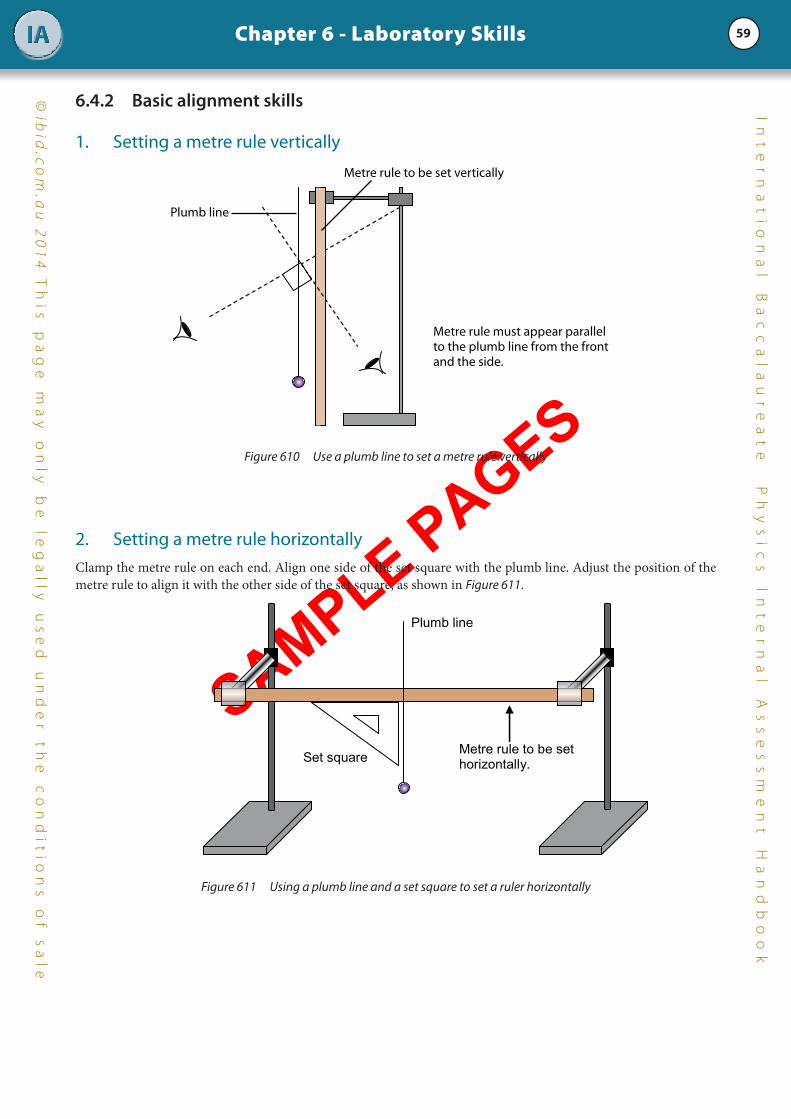
6.4.2 Basic alignment skills
1. Setting a metre rule vertically
Metre rule must appear parallel to the plumb line from the front and the side.
Plumb line
Metre rule to be set vertically
Figure 610 Use a plumb line to set a metre rule vertically
2. Setting a metre rule horizontallyClamp the metre rule on each end. Align one side of the set square with the plumb line. Adjust the position of the metre rule to align it with the other side of the set square, as shown in Figure 611.
Metre rule to be set horizontally.
Plumb line
Set square
Figure 611 Using a plumb line and a set square to set a ruler horizontally

SAMPLE PAGES
60
©ib
id.c
om
.au
20
14
Th
is p
ag
e m
ay
on
ly b
e le
ga
lly u
se
d u
nd
er
th
e c
on
dit
ion
s o
f sa
le
Chapter 6 - Laboratory SkillsIAI
nt
er
na
ti
on
al
B
ac
ca
la
ur
ea
te
Ph
ys
ic
s
In
te
rn
al
A
ss
es
sm
en
t
Ha
nd
bo
ok
6.4.3 Setting up an oscillation apparatus
The string or the spring’s end needs to be clamped tightly between two small wooden blocks. Do not simply tie the string to the clamp as this will affect the stability of the oscillation.
Figure 612 Setting up oscillating apparatus
6.4.4 Ticker timer to study motion
The speed of moving objects can be measured by using a ticker timer. A ticker timer is connected to an alternating current supply and makes 50 ticks or dots every second. The time interval ∆t between consecutive dots is
501
s or
0.02 s. (In some countries, the a.c. frequency is 60 Hz, hence ∆t = 601
s or 0.17 s.)
Terminals connected to 12 V a.c.
Ticker tape
Carbon paper
Moveable to adjust
Figure 613 A ticker timer
An example of a ticker timer tape record is shown in Figure 614.

SAMPLE PAGES
61
©ib
id.c
om
.au
20
14
Th
is p
ag
e m
ay
on
ly b
e le
ga
lly u
se
d u
nd
er
th
e c
on
dit
ion
s o
f sa
le
Chapter 6 - Laboratory SkillsIAI
nt
er
na
ti
on
al
B
ac
ca
la
ur
ea
te
Ph
ys
ic
s
In
te
rn
al
A
ss
es
sm
en
t
Ha
nd
bo
ok
time /s 0 0.1 0.2 0.3 0.4 0.5
3.0 cm 5.0 cm 7.0 cm 7.0 cm 4.2 cm
Start
one �vetick
A B C D E
First distinct dot
Figure 614 An example of a ticker tape
The speed of the object at different times is determined as follows:
i) Note the first distinct dot on the tape.
ii) Mark out all the “fiveticks” along the tape as shown above. A fivetick consists of 5 tick-spaces. Note that one 5 tick-space contains 6 dots. (You may use a ten-tick if the ticker tape record is quite long).
iii) Measure the length of each fivetick.
iv) The time interval for each fivetick is 0.1 s. (∆t = 5 × 0.02 s = 0.1 s).
v) The average speed for an interval is given by the ratio of its length and the time interval 0.1 s.
For example, the average speed for:
Interval A: average speeds
cms
cm 301.0
0.3==
Interval D: average speeds
cms
cm 701.0
0.7==
Note: If the a.c. frequency is 60 Hz, then it is most sensible to mark out your ticker tape into ‘sixticks’ or ‘twelveticks’
6.4.5 Hooke’s Law investigation• Use a pointer to enable you to accurately mark the position of the bottom of an unstretched spring and the new
position of the bottom of a stretched spring.
• Ensure that the spring is hung vertically.
• Wait for mechanical equilibrium to be established before recording the extension of the spring.
• Place the slotted masses on the mass holder carefully and slowly. The smaller the disturbance in the spring, the faster it reaches mechanical equilibrium.
Metre rule is clamped vertically and its scale is visible.
A horizontal pointer is placed to mark the extension of the spring.
The end of the spring is tightly clamped between two wooden blocks.
Avoid parallax error.
Figure 615 Measuring the extension of a spring

SAMPLE PAGES
62
©ib
id.c
om
.au
20
14
Th
is p
ag
e m
ay
on
ly b
e le
ga
lly u
se
d u
nd
er
th
e c
on
dit
ion
s o
f sa
le
Chapter 6 - Laboratory SkillsIAI
nt
er
na
ti
on
al
B
ac
ca
la
ur
ea
te
Ph
ys
ic
s
In
te
rn
al
A
ss
es
sm
en
t
Ha
nd
bo
ok
6.4.6 Timing oscillations (e.g. simple pendulum, loaded spring)• Have a marker behind the oscillating object that can be used to judge when the object passes the reference point.
Count each time it passes the marker in the same direction.
• It is good practice to time the oscillation when the object is at its fastest. For a simple pendulum or a loaded spring, it is at its fastest when it travels past its equilibrium position.
• Do not start the timer at the same time you start the oscillation because chances are, you cannot. Instead let the simple pendulum or the loaded spring oscillate a few times before you start the timer. Count ‘0’ as the object passes the marker and start the timer. When it passes the marker in the same direction, count ‘1’ and so on.
• Before oscillating a loaded spring, ensure that the slotted masses are securely attached to the mass holder and the mass holder is attached to the spring. Furthermore, do not excessively extend the spring when starting to oscillate it.
Marker for centre ofoscillation
Split cork
Thin string
Pendulum bob
One complete oscillation
Figure 616 Setting up oscillations for a pendulum
Marker for centre ofoscillation
Split cork
Spring
One complete oscillation
Figure 617 Setting up oscillations for a spring

SAMPLE PAGES
63
©ib
id.c
om
.au
20
14
Th
is p
ag
e m
ay
on
ly b
e le
ga
lly u
se
d u
nd
er
th
e c
on
dit
ion
s o
f sa
le
Chapter 6 - Laboratory SkillsIAI
nt
er
na
ti
on
al
B
ac
ca
la
ur
ea
te
Ph
ys
ic
s
In
te
rn
al
A
ss
es
sm
en
t
Ha
nd
bo
ok
6.4.7 Using electronic balances• Always tare to zero the electronic balance before using it. This eliminates the zero error.
• Warm up the electronic balance before using it. The required warming-up time is usually indicated on the balance. This is needed to enable all parts of the balance to equilibrate to the same temperature and therefore give stable readings.
• Place the object to be weighed on the centre of the pan. This ensures that a uniform pressure is applied on the mechanisms inside the balance and that more reliable results are obtained.
• Place objects carefully on the pan. Dropping objects on the pan can damage the electronic balance and affect the accuracy of the readings.
• Do not place a hot object directly on the pan. Use an insulating pad between the hot object and the pan if you need to measure the mass of a hot object.
6.4.8 Heat experiments
1. General skills• Use tongs to handle and safely transfer hot objects.
• Stir the hot liquid before measuring its temperature. This ensures that the liquid is at a uniform temperature. However, do not use the thermometer as a stirrer unless instructed to do so. (Some thermometers have reinforced bulbs and can be used as a stirrer.)
• Wait for the thermometer to reach thermal equilibrium before taking a reading.
• Ensure that the thermometer does not touch the bottom of the container when measuring the temperature of a liquid that is being heated. This is because the bottom of the container is hotter than the liquid. Ideally, the thermometer should be clamped as shown below.
The thermometer is clamped at the top part so as not to block the scale when reading higher temperatures.
rubber bung
The thermometer bulb must be fully immersed in the liquid and must nottouch any part of the container.
Avoid parallax error
Figure 618 Setting up a liquid-in-glass thermometer

SAMPLE PAGES
64
©ib
id.c
om
.au
20
14
Th
is p
ag
e m
ay
on
ly b
e le
ga
lly u
se
d u
nd
er
th
e c
on
dit
ion
s o
f sa
le
Chapter 6 - Laboratory SkillsIAI
nt
er
na
ti
on
al
B
ac
ca
la
ur
ea
te
Ph
ys
ic
s
In
te
rn
al
A
ss
es
sm
en
t
Ha
nd
bo
ok
2. Calorimetry Calorimetry is the name given to the experimental technique used to determine the heat energy absorbed or released during a chemical reaction. Calorimetry experiments in Physics use special containers called calorimeters (see Figure 619).
The outer calorimeter cup serves to insulate the inner calorimeter cup and its contents.
The inner calorimeter cup.
The stirrer Insulating stand
Figure 619 A calorimeter
a) Precautions to minimise heat losses
• Polish the inner part of the calorimeter to reduce heat loss due to radiation.
• Support the calorimeter on an insulating stand to reduce conduction losses.
• Place the inner calorimeter inside a larger calorimeter to reduce convection and conduction losses.
b) Initial cooling method
In this method, the calorimeter and its contents are cooled down to 10 0C below room temperature. It is then heated steadily by electrical means to 10 0C above room temperature.
When the substance is below room temperature, it will absorb heat from the surroundings. When the substance is above room temperature, it will lose heat to the surroundings. It is assumed that the heat absorbed by the substance when it is below room temperature is equal to the heat lost by the substance to the environment when it is above room temperature.
Note that you may cool down the calorimeter and its contents to a different temperature below room temperature. It is important that the calorimeter is cooled below room temperature by the same amount that it will be increased above room temperature.
It is possible that the calorimeter and its contents are heated up first and then cooled down. As an example, the specific latent heat of fusion of ice can be obtained by the method of mixtures. In this method, a known mass of ice is mixed with a known mass of water. Temperature changes are measured and the specific latent heat of fusion of ice is calculated. More accurate results would be obtained if the water-calorimeter system is heated up first, i.e. to around 10 0C above room temperature. You then need to estimate the mass of ice you need to mix with the water so that the final temperature of the water-ice-calorimeter system is approximately 10 0C below room temperature.

SAMPLE PAGES
65
©ib
id.c
om
.au
20
14
Th
is p
ag
e m
ay
on
ly b
e le
ga
lly u
se
d u
nd
er
th
e c
on
dit
ion
s o
f sa
le
Chapter 6 - Laboratory SkillsIAI
nt
er
na
ti
on
al
B
ac
ca
la
ur
ea
te
Ph
ys
ic
s
In
te
rn
al
A
ss
es
sm
en
t
Ha
nd
bo
ok
c) Determination of the specific latent heat of fusion of water by an electrical method
This is one investigation where your manipulative skills will be very important.
Electrical heater Ice in funnel Wire gauze to prevent small bits of ice passing through the funnel.
Low voltage power supply
V
A
(a) Experimental apparatus (b) Control apparatus
Stop watch
Figure 620 Experimental set-up to measure the specific latent heat of fusion of ice
A concern with this method is that the ammeter and voltmeter readings change over time. This is because the resistance of the electric heater increases as its temperature increases. Prepare a table similar to Figure 621 so you will have a more accurate value of the electrical energy supplied over the 10 minute period.
Time elapsed
/ min
Voltage
/ V
Current
/ A
Power
/ W
Electrical energy
/ J
0.0 Current × Voltage Power × 30 s
0.5
1.0
↓ 10.0
Total electrical energy
Figure 621 A sample table

SAMPLE PAGES
66
©ib
id.c
om
.au
20
14
Th
is p
ag
e m
ay
on
ly b
e le
ga
lly u
se
d u
nd
er
th
e c
on
dit
ion
s o
f sa
le
Chapter 6 - Laboratory SkillsIAI
nt
er
na
ti
on
al
B
ac
ca
la
ur
ea
te
Ph
ys
ic
s
In
te
rn
al
A
ss
es
sm
en
t
Ha
nd
bo
ok
6.4.9 Electricity experiments
1. Building electric circuits• Ensure that the power is switched off when connecting the components together or when taking them apart.
• If you have to build a circuit from a schematic diagram, follow the polarities of the components. For ammeters and voltmeters, it is positive terminal to positive terminal.
• When building electric circuits, there must be a minimum of tangles, or if possible none at all, so that the circuit can be easily followed. Tangles can be reduced or avoided by completing the series part of the circuit first and connecting the electrical component that has to be connected in parallel last (e.g. voltmeter).
• It is important to keep the temperature of the electrical components constant. Turn on the electrical circuit when you are ready to take a reading and turn it off to allow the component to cool.
2. Use of analogue ammeters and voltmeters• Before using, give the moving-coil part of the ammeter or voltmeter a gentle tap. This is to loosen the coil parts
just in case there is some residual friction in it.
• Check that the ammeter or voltmeter reads zero before connecting it to the circuit. If it does not, with your teacher’s permission, you can set the needle pointer to zero by adjusting the screw at the base of the pointer (see Figure 622).
• To avoid parallax error, analogue ammeters and voltmeters are equipped with a strip of mirror on the scale. Position your eyes vertically above the needle, such that the needle and its image on the mirror coincide.
(a) Voltmeter scale with zero error
Zero adjustment screw
Strip of mirror to eliminate parallax error
Positive terminal (red)
Negative terminal (black)
(b) An ammeter
Figure 622 An analogue voltmeter and ammeter

SAMPLE PAGES
67
©ib
id.c
om
.au
20
14
Th
is p
ag
e m
ay
on
ly b
e le
ga
lly u
se
d u
nd
er
th
e c
on
dit
ion
s o
f sa
le
Chapter 6 - Laboratory SkillsIAI
nt
er
na
ti
on
al
B
ac
ca
la
ur
ea
te
Ph
ys
ic
s
In
te
rn
al
A
ss
es
sm
en
t
Ha
nd
bo
ok
3. Connecting an ammeter and voltmeterThe ammeter must be connected in series to the circuit in order to measure the current passing through the circuit. On the other hand the voltmeter is connected in parallel to the device to measure the potential difference across the device. See Figure 623.
The terminals of the ammeter and the voltmeter have a polarity. They need to be connected to the correct poles of the power source. The red terminal is positive (remember ‘red cross’) while the black terminal is negative. To work properly, the positive terminal of the ammeter or of the voltmeter must be connected to the positive side of the power source.
4. Dual range ammeter and voltmeterA dual range ammeter or voltmeter has three terminals (one negative terminal and two positive terminals) and two scales. When using this type of ammeter or voltmeter, it is critically important that you read the correct scale.
Take the voltmeter below (Figure 624) as an example. It has three terminals: 0 V (terminal A), 3 V (terminal B), and 15 V (terminal C). It has two scales: the upper scale reads 0 – 15 V while the lower scale reads 0 – 3 V. Since the maximum reading for the upper scale is 15 V, it has a full scale deflection (fsd) of 15 V. The lower scale has a fsd of 3 V.
When terminals A and B are connected to the circuit, the voltmeter can measure up to a maximum of 3 V. You must therefore read the lower scale. On the other hand, when terminals A and C are connected to the circuit, the voltmeter can measure up to a maximum of 15 V and you must read the upper scale. Note that it is not possible to connect the three terminals concurrently to the circuit.
A B C
The upper scale has a full scalede�ection of 15 V T he lower scale has a full scalede�ection of 3 V
Terminal C is a positive terminal that can measure up to a maximum of 15 V Terminal B is a positive terminal that can measure up to a maximum of 3 V Terminal A: 0 V (negative terminal)
Figure 624 A dual range voltmeter
V
A
+ -
- +
+ -
Figure 623 Connecting the ammeter and voltmeter

SAMPLE PAGES
68
©ib
id.c
om
.au
20
14
Th
is p
ag
e m
ay
on
ly b
e le
ga
lly u
se
d u
nd
er
th
e c
on
dit
ion
s o
f sa
le
Chapter 6 - Laboratory SkillsIAI
nt
er
na
ti
on
al
B
ac
ca
la
ur
ea
te
Ph
ys
ic
s
In
te
rn
al
A
ss
es
sm
en
t
Ha
nd
bo
ok
5. Multi-range metersA multi-range meter has two components: a milliammeter or microammeter and a series of specially-mounted resistors. A milliammeter is a galvanometer that can measure currents within the range of 10-3 A (mA) while a microammeter can measure very small currents within the range of 10-6 A (µA). The unit stamped on the meter will tell you whether it is microammeter or a milliammeter (see Figure 425). The specially-mounted resistors are designed to be connected in parallel (i.e. as shunts) to produce a range of ammeters or in series (ie, as multipliers) to produce a range of voltmeters.
Consider the multi-range meter below (Figure 625) as an example. The multiplier resistor will convert the microammeter into a dual range voltmeter with fsd 1 V and 5 V. The shunt resistor will convert the microammeter into a dual range ammeter with fsd 1 A and 5 A.
As various shunt and multiplier resistors can be mounted onto the microammeter, care must be exercised when reading the scale. If the fsd of the mounted multiplier or shunt resistor is 5 V or 5 A, common sense tells you to read from the upper scale. However, if the fsd is some other value (e.g. 2.5 A), then the correct reading can be obtained by using the formula:
scaleonreadingmaximumscaleonreadingrawvaluefsdreadingcorrect ×= .
For example, the maximum reading on the upper scale is 10.00 A and the raw reading is 7.60 A. The shunt resistor has a fsd of 2.5 A. Then the correct reading is:
Correct reading = 2.5 00.1060.7
× = 1.90 A
A microammeter
The multiplier resistor converts the microammeter into a dual range voltmeter with fsd 5 V and 1 V.
The shunt resistor converts the microammeter into a dual range ammeter with fsd 5 A and 1 A.
The upper scale has a range of -2 to 10units. The lower scale has a range of -1 to 5 units.
Figure 625 A multi-range meter

SAMPLE PAGES
69
©ib
id.c
om
.au
20
14
Th
is p
ag
e m
ay
on
ly b
e le
ga
lly u
se
d u
nd
er
th
e c
on
dit
ion
s o
f sa
le
Chapter 6 - Laboratory SkillsIAI
nt
er
na
ti
on
al
B
ac
ca
la
ur
ea
te
Ph
ys
ic
s
In
te
rn
al
A
ss
es
sm
en
t
Ha
nd
bo
ok
6. Using an ammeter and a voltmeter to measure resistance Moving coil galvanometers used as ammeters or voltmeters need a small amount of current to operate. As such, the use of these devices changes the current flowing in the circuit. See Figure 626.
An ammeter is connected in series to the circuit. For it to have minimal effect on the current, it should have a very small resistance. Since it is connected in series, its presence increases the total resistance. This additional resistance, though small, causes the current in the circuit to decrease.
A voltmeter, on the other hand, is connected parallel to the circuit. For it to have minimal effect on the current, it should have a very high resistance. The voltmeter creates an extra parallel branch and as such, it draws additional current. However, due to its very high resistance, the current drawn by the voltmeter is very small. Even so, the voltmeter causes an increase, however minimal, to the total current in the circuit.
I I R I V
A
V
R
The current (I) measured by the ammeter is higher than the actual current (I R ) that�ows through the resistor. The voltmeter draws a current I V.
IR is much larger than I V.
Figure 626 Systematic error due to the voltmeter
A voltmeter and an ammeter are used in tandem to determine the resistance of a conductor or of a resistor. How the two devices are to be connected depends on the resistance of the conductor relative to the resistance of the voltmeter.
Measuring small resistances
When the resistance R of the resistor is much smaller compared to the resistance of the voltmeter, the circuit in Figure 627 is used to determine the resistance R.
In the circuit the resistance of the voltmeter is much higher. As a consequence, it draws a small current and this increases the total current in the circuit. Therefore, the current measured by the ammeter is higher than the actual current flowing through the resistor.
Since IVR = , then the calculated resistance R is underestimated. This is an example of a systematic error.
I IR IV
A
V
R
Figure 627 Ammeter-voltmeter connection to determine low resistances
SAMPLE PAGES
70
©ib
id.c
om
.au
20
14
Th
is p
ag
e m
ay
on
ly b
e le
ga
lly u
se
d u
nd
er
th
e c
on
dit
ion
s o
f sa
le
Chapter 6 - Laboratory SkillsIAI
nt
er
na
ti
on
al
B
ac
ca
la
ur
ea
te
Ph
ys
ic
s
In
te
rn
al
A
ss
es
sm
en
t
Ha
nd
bo
ok
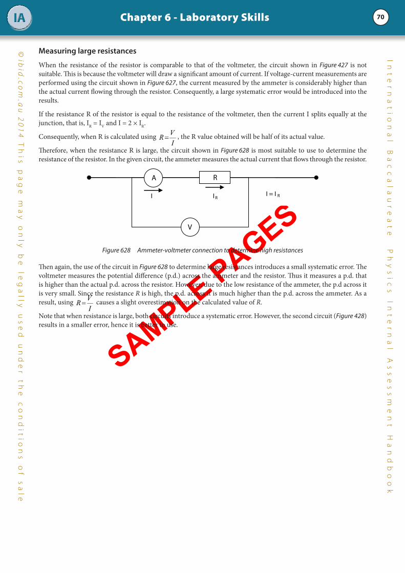
Measuring large resistances
When the resistance of the resistor is comparable to that of the voltmeter, the circuit shown in Figure 427 is not suitable. This is because the voltmeter will draw a significant amount of current. If voltage-current measurements are performed using the circuit shown in Figure 627, the current measured by the ammeter is considerably higher than the actual current flowing through the resistor. Consequently, a large systematic error would be introduced into the results.
If the resistance R of the resistor is equal to the resistance of the voltmeter, then the current I splits equally at the junction, that is, IR = IV and I = 2 × IR.
Consequently, when R is calculated using IVR = , the R value obtained will be half of its actual value.
Therefore, when the resistance R is large, the circuit shown in Figure 628 is most suitable to use to determine the resistance of the resistor. In the given circuit, the ammeter measures the actual current that flows through the resistor.
V
A R
I I R
I = I R
Figure 628 Ammeter-voltmeter connection to determine high resistances
Then again, the use of the circuit in Figure 628 to determine large resistances introduces a small systematic error. The voltmeter measures the potential difference (p.d.) across the ammeter and the resistor. Thus it measures a p.d. that is higher than the actual p.d. across the resistor. However, due to the low resistance of the ammeter, the p.d across it is very small. Since the resistance R is high, the p.d. across it is much higher than the p.d. across the ammeter. As a result, using
IVR = causes a slight overestimation on the calculated value of R.
Note that when resistance is large, both circuits introduce a systematic error. However, the second circuit (Figure 428) results in a smaller error, hence it is better to use.

SAMPLE PAGES
71
©ib
id.c
om
.au
20
14
Th
is p
ag
e m
ay
on
ly b
e le
ga
lly u
se
d u
nd
er
th
e c
on
dit
ion
s o
f sa
le
Chapter 6 - Laboratory SkillsIAI
nt
er
na
ti
on
al
B
ac
ca
la
ur
ea
te
Ph
ys
ic
s
In
te
rn
al
A
ss
es
sm
en
t
Ha
nd
bo
ok
7. Rheostat A rheostat is a resistor that has a variable resistance and it is an important instrument for controlling current. It has three terminals. You have to connect the wires to the correct terminals of the rheostat to achieve a varying resistance when the slider is moved. The diagrams in Figure 629 describe how the resistance between points x and y changes when different terminals of the rheostat are used.
THE RHEOSTAT AS A FIXED RESISTOR
Moving the slider does not change the resistance
x y
x y
Equivalent circuit diagram
THE RHEOSTAT AS A VARIABLE RESISTOR
Moving the slider to the right increases the resistance
x
y x
y
y x
Moving the slider to the right decreases the resistance
x y
Figure 629 The terminals connected to the circuit affects how its resistance changes

SAMPLE PAGES
72
©ib
id.c
om
.au
20
14
Th
is p
ag
e m
ay
on
ly b
e le
ga
lly u
se
d u
nd
er
th
e c
on
dit
ion
s o
f sa
le
Chapter 6 - Laboratory SkillsIAI
nt
er
na
ti
on
al
B
ac
ca
la
ur
ea
te
Ph
ys
ic
s
In
te
rn
al
A
ss
es
sm
en
t
Ha
nd
bo
ok
8. Measurement of magnetic forceAn electronic balance can be used to measure the magnetic force on a current-carrying conducting wire. Figure 630 shows how this can be done.
Alligator clip
These terminals are connected into the circuit
Conducting wire
U-shaped magnet
Electronic balance
A
Conducting wire in the magnetic �eld
Rheostat
Figure 630 Experimental set-up to measure the magnetic force on a current-carrying conducting wire
A U-shaped magnet is placed on the top of the electronic balance. The conducting wire is fixed horizontally between the poles of the magnet such that the length lies in the field of the magnet. The conducting wire is connected into the circuit shown above. The current flowing in the conducting wire can be varied through the rheostat.
When a current is flowing through the conducting wire, the magnet will experience an upward or a downward force, depending on the direction of the magnetic field of the U-shaped magnet and of the current. Either way, this will result in a change in the electronic balance reading, that is, the reading in the electronic balance may increase or decrease. The change in the electronic balance reading is proportional to the force between the conducting wire and the U-shaped magnet. The force is obtained by multiplying the change in the electronic balance reading (in kg) by 9.8 N/kg.
Note that the strength of an electromagnet can be investigated in the same manner by replacing the conducting wire by the electromagnet.

SAMPLE PAGES
73
©ib
id.c
om
.au
20
14
Th
is p
ag
e m
ay
on
ly b
e le
ga
lly u
se
d u
nd
er
th
e c
on
dit
ion
s o
f sa
le
Chapter 6 - Laboratory SkillsIAI
nt
er
na
ti
on
al
B
ac
ca
la
ur
ea
te
Ph
ys
ic
s
In
te
rn
al
A
ss
es
sm
en
t
Ha
nd
bo
ok
6.5 Working safelyYour approach to safety during investigations in the laboratory or in the field is very important. Nevertheless, the IB Physics teacher will not put you, the students, in situations of unacceptable risk.
In Physics laboratories there are many potential hazards and your safety depends on your awareness and understanding of these. In most cases, these hazards will be dealt with by your teacher as they arise, often in connection with the investigation. Any practical work should be approached sensibly and carefully. If there is anything you do not understand, ask your teacher first.
Listed and discussed below are the types of dangers that can cause problems or injuries when performing IB Physics investigations.
6.5.1 What you need to do • Carry out laboratory work only when supervised by a teacher.
• Use common sense. Accidents during an investigation can be avoided if you, the student, have really thought about what you need to do.
• Listen to instructions carefully. Ask your teacher if there is anything unclear to you.
• Before doing anything, remove all clutter from your work bench.
• Before starting, ensure that you have all the necessary apparatus, equipment and material. This prevents you from stopping your investigation halfway through to locate missing equipment.
• Stay in your work area and monitor your investigation closely.
• Consult your teacher before making any modification in the suggested method.
• If you need to handle any potentially dangerous substances, wear gloves and wash your hands thoroughly after the investigation.
• Before you leave your work area, ensure that the water, electricity and gas are all turned off. Equipment should be returned to its proper storage place.
6.5.2 Mechanics investigations
Investigations in mechanics usually involve rapidly moving objects, falling objects and stretched springs. Being hit by rapidly moving objects can produce bruises, scratches and cuts. Safety precautions are mostly common sense.
Projectiles • Pre-test the projectile to determine the path it will take. Ensure that no one is along the path or the impact area.
• Do not use sharp-pointed objects as projectiles.
• Wear safety goggles.
• Use a simple mechanical launcher (e.g., compressed spring, compressed air, stretched elastic). Load the launcher only when it is to be fired.
Falling objects and moving equipmentHeavy masses may be used in experiments involving Atwood’s machine, free fall, Newton’s laws, and momentum. Care should be taken to prevent hands and feet from being caught between a moving heavy mass and the floor or table surfaces. For falling objects, always place a ‘crash box’ (a box which contains a soft material that will cushion the fall of the object and prevent it from bouncing).

SAMPLE PAGES
74
©ib
id.c
om
.au
20
14
Th
is p
ag
e m
ay
on
ly b
e le
ga
lly u
se
d u
nd
er
th
e c
on
dit
ion
s o
f sa
le
Chapter 6 - Laboratory SkillsIAI
nt
er
na
ti
on
al
B
ac
ca
la
ur
ea
te
Ph
ys
ic
s
In
te
rn
al
A
ss
es
sm
en
t
Ha
nd
bo
ok
Powerful permanent magnetsLarge permanent magnets and electromagnets may attract opposite poles or steel objects with an unanticipated strong force. There is the potential risk that fingers get pinched when caught between the magnet and the metallic object.
Stretched or compressed springs Care should be taken to avoid unexpected release of the spring’s potential energy when working with dynamics carts, spring-type simple harmonic oscillators, and springs used in wave investigations. A stretched spring, unexpectedly released, can tweak fingers. A compressed spring, when suddenly released, can hit someone or send a projectile at high velocity toward an observer.
6.5.3 Heating• Loose fitting clothes or long hair not tied back can pose a hazard when working with a naked flame.
• Beakers of liquid on a tripod are tall structures that are top heavy and can easily fall over. Place them on the centre of the work bench to reduce the chances of them being accidentally knocked down.
• Know where the fire blanket, fire extinguisher and sand bucket are before starting an investigation which will utilise a naked flame,
• Many materials like glass remain hot for a long time after they are removed from the heat source. Always check an objects’ temperature by bringing the back of the hand near it before attempting to pick it up without tongs, hot pads, or gloves.
• Never set hot glassware on cold surfaces or change its temperature suddenly (e.g. pouring cold water), because uneven contraction may cause breakage.
• Never heat a closed or sealed container that has no means to release pressure.
• Make sure that steam outlets are not directed towards yourself or to anyone else.
6.5.4 Laser
The laser produces an intense, highly directional beam of light that can cause burns and retinal damage. Some lasers concentrate visible light to an extent that retinal damage can occur in a very short time. Fortunately, lasers found in secondary school science laboratories are the low power (0.5 – 3.0 mW) helium-neon lasers. Nonetheless, they should be handled with great care and certain precautionary measures need to be taken when working with lasers.
• Never put your eye directly in path of the laser beam.
• Ordinary safety goggles or sun glasses will not protect your eyes against lasers.
• When using lasers, do not darken the room more than is necessary as this dilates or enlarges the pupil. A dilated pupil is more prone to damage when accidentally hit by laser light.
• Before switching on the laser, remove any reflective material or object that lies in the path of the laser beam. Ensure that there is no possibility of multiple reflections. In this regard, do not use the laser in rain, snow, fog or heavy dust.
• Investigations using a laser should not be set up at eye level.
• Do not move the laser when it is on.
• Do not leave the laser unattended.
• When the laser is not in use, block off the beam or better still, turn it off.

SAMPLE PAGES
75
©ib
id.c
om
.au
20
14
Th
is p
ag
e m
ay
on
ly b
e le
ga
lly u
se
d u
nd
er
th
e c
on
dit
ion
s o
f sa
le
Chapter 6 - Laboratory SkillsIAI
nt
er
na
ti
on
al
B
ac
ca
la
ur
ea
te
Ph
ys
ic
s
In
te
rn
al
A
ss
es
sm
en
t
Ha
nd
bo
ok
6.5.5 Ultraviolet (UV) rays• UV rays pose a danger to the eyes. When a UV lamp is used, it should be shielded. You need to wear
eye protection.
• UV rays used for investigating the photoelectric effect have short wavelengths and they do not transmit through ordinary glass. Therefore, ordinary glass may be used as a shield.
• Turn off the UV lamp when not in use.
6.5.6 Electricity
Safety measures in investigations using electricity are as follows:
• Use only low voltage (LT) power packs which have a maximum of 12 V.
• During initial experiments, ask your teacher to check your circuit before switching it on.
• Monitor the temperature of your wires. When the circuit is on, feel the wires by putting the back of your hand close to it but not touching it. If they are warming up, there is a current overload. Reduce the current by lowering the emf or by increasing the resistance.
• When part of the circuit has been assembled, check that the ammeter and voltmeter are deflected in the right direction. This can be safely done by quickly touching the final connection to one terminal of the power pack.
• Damaged three-pin plugs, exposed wires and worn and frayed leads must be reported to the teacher immediately.
• Always switch off your circuit when making any changes to it.
• The use of high voltage (HT) and extra high voltages (EHT) are usually reserved for teacher demonstrations. Experiments with EHT, for example in electrostatics or cathode rays, can involve a few thousand volts. If you are instructed to use EHT, the current must be limited to a few milliamperes.
• For completed circuits to watch out for:
• hand-to-hand connections that allow current to flow through the heart
• hand-to-ground connections that allow for maximal current flow through the body.

SAMPLE PAGES
76
©ib
id.c
om
.au
20
14
Th
is p
ag
e m
ay
on
ly b
e le
ga
lly u
se
d u
nd
er
th
e c
on
dit
ion
s o
f sa
le
Chapter 6 - Laboratory SkillsIAI
nt
er
na
ti
on
al
B
ac
ca
la
ur
ea
te
Ph
ys
ic
s
In
te
rn
al
A
ss
es
sm
en
t
Ha
nd
bo
ok
6.5.7 Radioactive sources
Radioactive sources used in the laboratory are relatively weak emitters. The α, β and γ sources that are used for the Geiger-Muller tubes are mounted in metal holders and one face is open. The source is held in place inside by gauze or a wire mesh. These sources always come in lead-lined containers.
Listed below are some precautions to be followed when handling radioactive sources.
• Use the radioactive source only if you have permission from your teacher and when your teacher is present in the laboratory.
• The radioactive sources must always be transported in their containers.
• Keep your exposure to the radioactive source to a minimum. Prepare everything and ensure that apparatus and equipment are all set-up before taking out the radioactive source from its container.
• Use one radioactive source at a time. Return one radioactive source to its container before using another.
• Always use a pair of tongs or forceps when handling radioactive sources. Hold the forceps with stretched arms and keep the radioactive source as far as possible from your body. Wear protective gloves if available.
• Always make sure that the open face of the radioactive source is pointing away from you and from anybody else.
• Do not tamper with any radioactive source. Report to your teacher if you observe any damage in the radioactive source.
• Wash your hands thoroughly after handling radioactive sources.
6.6 Risk AssessmentBasic safety instructions are described in the IBID Press Physics Practical Investigations and potential hazards are identified in the investigations described. However, sometimes the investigation will be more open-ended, for example, your Group 4 Project or your Individual Investigation.
If you are planning your own practical work, then your IB Physics teacher will need to approve your plans from the point of view of safety. You are also required to take into account any environmental impact your investigation may have.
A Risk Assessment is a way of identifying and assessing risks and hazards associated with the materials and equipment that you plan to utilize in an investigation. This includes predicting what might go wrong, how likely it is to go wrong and how severe the consequences would be.
Figure 632 A laboratory laser

SAMPLE PAGES
77
©ib
id.c
om
.au
20
14
Th
is p
ag
e m
ay
on
ly b
e le
ga
lly u
se
d u
nd
er
th
e c
on
dit
ion
s o
f sa
le
Chapter 6 - Laboratory SkillsIAI
nt
er
na
ti
on
al
B
ac
ca
la
ur
ea
te
Ph
ys
ic
s
In
te
rn
al
A
ss
es
sm
en
t
Ha
nd
bo
ok
The stages in carrying out a Risk Assessment are given below:
1) Identify the nature of the risk. For IB Physics investigations, the hazard may be one of the following:
a) Ultraviolet rays/ Lasers
b) Nuclear Radiation
c) Naked Flame/Hot equipment/Hot Liquid
d) Moving Objects/Heavy Objects/Sharp objects
e) Compressed/Stretched Springs or wires
f) Electricity
2) Assess the hazards.
a) What is the worst case scenario that could happen?
i) First aid is enough
ii) Medical attention
iii) Serious medical attention
iv) Permanent disability
v) Fatal
b) What is the possibility that this will happen?
i) High
ii) Medium
iii) Low
3) Control the hazards. This means thinking about and implementing measures that can reduce or eliminate the risks and hazards related to the investigation.
a) Can you eliminate it?
b) Can you substitute a less hazardous alternative?
c) Can you change the way the task is done?
d) Will you have to use personal protective equipment?

SAMPLE PAGES
78
©ib
id.c
om
.au
20
14
Th
is p
ag
e m
ay
on
ly b
e le
ga
lly u
se
d u
nd
er
th
e c
on
dit
ion
s o
f sa
le
Chapter 6 - Laboratory SkillsIAI
nt
er
na
ti
on
al
B
ac
ca
la
ur
ea
te
Ph
ys
ic
s
In
te
rn
al
A
ss
es
sm
en
t
Ha
nd
bo
ok
4) Overall assessment
RISK ASSESSMENT FORM
Title of investigation Completed by
……………………………………………………….. ………………………………………………………..
Date
Approved by Nature of risk
Ultraviolet rays/ Lasers Naked flame/Hot equipment/Hot Liquid
Electricity
Nuclear Radiation Moving/Heavy/ Pointed Objects
Compressed/Stretched Spring or wire
What harm can these risks bring?
Worst case scenario
Possibility of occuring
What can be done to avoid or reduce risks?
High Medium Low
High Medium Low
High Medium Low
High Medium Low
Overall risk assessment
Insignificant
Significant but effectively controlled
Significant and not readily controlled
Comment : ……………………………………………………… ……………………………………………………….
……………………………………………………….
Figure 633 A sample of a Risk Assessment form