page1ofl - far circuits detector.pdfsemel! coil fig. 1. variations of fr~
TRANSCRIPT
Page 1 ofl
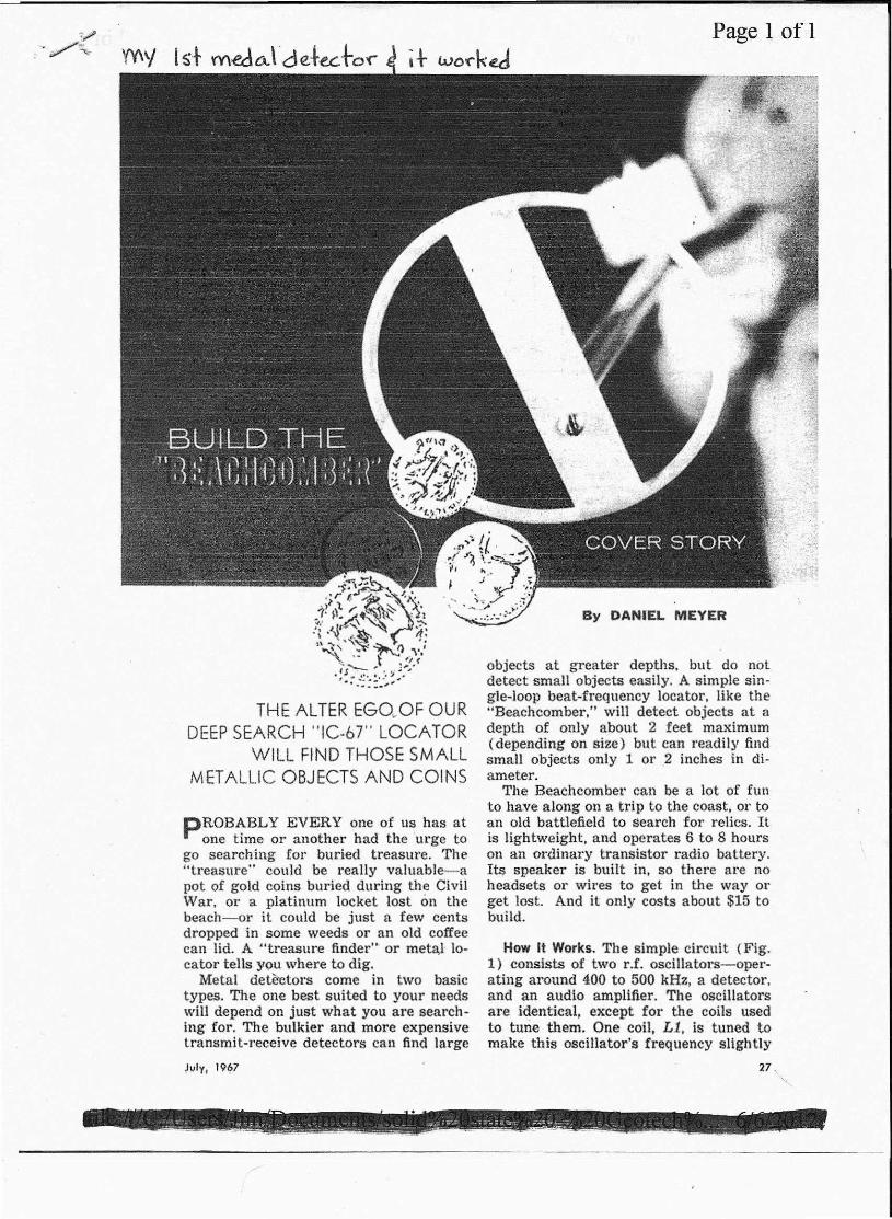
THE ALTER EGQ,.OF OURDEEPSEARCH "IC·67" LOCATOR
WILL FIND THOSE SMALLMETALLIC OBJECTS AND COINS
pROBABLY EVERYone of us has atone time or another had the urge to
go searching for buried treasure. The"treasure" could be really valuable-apot of gold coins buried during the CivilWar, or a platinum locket lost on thebeach-or it could be just a few centsdropped in some weeds or an old coffeecan lid. A "treasure finder" or metal 10·cator tells Y9U where to dig.
Metal deteetors come in two basictypes, The one best suited to your needswill depend on just what you are search-ing for. The bulkier and more expensivetransmit-receive detectors can find large
July, '9~7
By DANIEL MEYER
objects at greater depths, but do notdetect small objects easily. A simple sin-gle-loop beat-frequency locator, like the"Beachcomber,' will detect objects at adepth of only about 2 feet maximum(depending On size) but can readi Iy findsmall objects only 1 or .2 inches in di-ameter.
The Beachcomber can be a lot of funto have along on a trip to the coast; or toan old battlefield to search for relics. Itis lightweight, and operates 6 to 8 hourson an 'Ordinary transistor radio battery.Its speaker is built in, so there are noheadsets 01' wires to get in the way orget lost, And it only costs about $15 tobuild.
How It Works, The simple circuit (Fig.1) consists of two r.f. oscillators-oper-ating around 400 to 500 kHz, a detector,and an audio amplifier. The oscillatorsare identical. except for the coils usedto tune them. One coil, Ll, is' tuned tomake this oscillator's frequency slightly
27 \'..
- .__ ,,_:-_: ~ :::;::_e,,~_~~~...:::; __ ~,_ ~__ "::"-:"::''';__: ;i ..-::;;-~:-~ ::,,-:::,:,~_r ~_;.~..~_ ....:.-.::..__ ~ ...._""'""- _ __ _

RS33K
R'fII<
RIO101(
+
AI?II(
RI~4.1K
R14'11<
IIOrE: L.ETTERS .1"'OICA-TE. COp.;NECTIONPOINTS TO PRINTEO CIRCOIT
higher or lower then that of the searchcoil oscillator. The two signals are corn-bined in detector stage Q3, whose OUt.-
put is the andible difference between thetwo frequencies. This signal is fed toemitter follower Q4 and output stageQ5, and finally to the speaker.The search coil oscillator. frequency
changes slightly whenever the conduc-tance of the material in the field of theloop changes. This means that if the coilpasses over a metal object, the oscillatorfrequency will change slightly, and thepitch of the audio beat note you heal'from your speaker will also change. It iseasier to hear a small frequency changein a low-pitched sound than an equalchange in a higher frequency tone.
To get the best results from the Beach-comber, set the oscillators as neal' thesame frequency as possible. Both oscil-lator« must be 'very stable. Good sturdyconstruction with no loose parts is amust, The circuit must also be so laidout as to reduce coupling between thetwo oscillators to the minimum. Other-28
1.2SEMel! COIL
Fig. 1. Variations of fr~<lu~ncy of th~ Ql cir-cuit. caused by "pickup" of a metallic objectin U's field arc compared with the Q2 oscll-tater's output. and the difference Signal ispassed on to the speaker through Q3, Q4. andQ5. Nontinear operation of Q5 "encourages"generation of harmonics of the difference sig.nal which can be more efficiently handledby the speaker, and heard by the listener.
Page 1 of!
SI
,,19V-
PARTS UST[J !-f)'1ioit balleryCT. C.5-0./-'JIP,lo·;t"_'ortugc tlisc cr;/'(Jllfir GUfJ<!fi.
lotC1. C6-0.QU/-J!F POI,l'.flYTCIII: capacitorCJ. C7---O.0J·jtF fIQI~·$(.I'fCillr; capacitorC4. cs, C i:J-I0'}JF, H-t'oft dccirolvtic capacitorn). C /(J-.I.i-pP WfIIlJIJ(, disi: capacitorC 11-0.(}.I.iJP.l'tlw-:I(llltJ~c disc ceramic cnpoclto«C 12-2(J~-1f"'. ti.::,olt drctrotytic caoacltorC1;:J-iJ.Z2~jtF loill-lIQllOKC disc ceramic capacitorL 7-,jQ-J()O·J,11 uariab!« ;iIi!"ct(Jr ('j'/iQrdIiTSall
IfIC-l!;J:W. ?.fillcr :;::611)6,or similar}12--$,;orr./t CDiI-sl;I' irst{)1. (J~-;l.IPSJ6JS transistor (illol()rolu)OJ. (J4. O.j-M PS,liOS transistor (M%rola)R 1. lU-33,O(J() atints .?R2 . .R6-1'1,OQO (lilm.sR.J. RI/. R7, RS, /U2. RJ;1 .·HI
--WOO otuns resistorsRIJ-lOa,UOO Villi/of ) Y, ~-ua/IN 10. I? II-/(J.OOO O"IIISR1J-4700 ohmsSf-S.p,s.l. slille Stuil(/I'F I-Tramis/.ol' oul.p/ll treusjnr mer: pl'illl(Ir~', ;i()i)
O"/1I.~ CT {do 11(11 'lSI: (.'1') ; secondur»; .~ ohms,15(/ HIW_
,1Ji.<I;.-li1i1ll(JiIITC Sllcllka. cJw.f.is box, bulll'rydip. iIllamdeu seirc, spacers. solder .• uc,
>
",OTt::: Prlnied circuit. board for this project isavatlable . Ior $2.50 (rom D E;\'ICO. 219 WcHRhupsody,.$ilO Arltonio. Texas 7821 (,. ,\ CMlptclCkit. (Ill(tludint: tile tillil form. chns~is .Mld .ro.1) isalso flvailrlblc lor $15 postpaid.
~~ ----------------------------------------------------------------------------------- -~
POPULAR ELECTRONICS

r ..
wise, the oscillators will "puU"-slldden-Iy lock together every time the beat fre-quency is brought down to a low pitch.That is why both oscillators are de-coupled from the battery supply ami fromeach other ( througu R4-C4 and RS-C8)and why such small value capacitors areused [or C9 and Cl0.
The output stage is purposely designedto produce "distortion," so that the low-frequency beat notes can be heard fromthe small speaker. If the audio cir-cuit were designed for linear operationand little distortion, the speaker wouldproduce lIttle or no output below 150to 200 hertz. In this circutt the audio out-put stage is not biased "on" at. all. Whenit is driven with an audio signal fromemitter follower QJ" transistor Q5 con-ducts and produces an output on eachpositive half cycle. The signal to thespeaker is tnerefore a series of pulsesat the frequency of the beat signal. Sincethe pulses contain many harmonics, theycan be heard down to a few hertz.
Construction. The electronic portion ofthe metal detector is easy to assemble,and there, is no 'chalice:Of coupling prob-lems or shifting parts .i.t the printed cir-cuit board construction shown is used.,1'he board (Fig. 2) serves as a templateto locate the holes for L1, the mountingspacers, and the sp'~altei~.
Cut a 7'J41Il-c'iiamete.r hole for L.1 andanother of the correct diameter for your
- J
Page 1 of 1
speaker. Then mount the small partsby simply inserting them in the positionsindicated by the parts numbers on thetop side of the board, turning the boardover, and soldering them in place.File the switch hole in the cabinet to
fit the type of switch used. Mount theswitch, speaker, battery clip, and Ll as.shown in the photograph (Fig. 3). Wirethe switch and battery clip as shown.The lead from the positive terminal ofthe battery goes to one switch contact,and a short lead should be soldered tothe other eontact=-to go to point 1:1'onthe board. A doughnut cut from plasticfoam is placed around the rear of thespeaker; the board compresses the foamwhen it is mounted, and thus holds thespeaker snugly.
Now connect the battery and speakerwires to the underside of the board atthe points indicated on the schematicdiagram. Mount the completed circuit
.f,Y' . - '~-i:: -c ; •••• " ••
. CJC '0' ;;;;:,.:.t ~;.,o ~6~14@'_ f\ ~...•fF"~ ..1-.8+,.,! 6 ., .11.. .i f Cl t, AT f. ,_,' -t. D.,ot> Rl j C$·1 15
, f" 1 • b~'0' 0 T 0 &10m cn~ oCJ1 Rl T c• ~: ... C! I RI 0 as
,,~" m + . . '" ,0 wp o? ~ + 0 •oo:.~o.o . q·o 00 ..0. ~~'Il~.(+' I t2 0 t «. : \~.tt-O)' ,!en llQ ~ ~ A R2~
." _ ,,,,.,i?, .1;,>~ .08 HI~'r • __ , 00
Fig. 2. Actual size draw-ing of foil side 'of printedcircuit (left) will help youmake your own board. Partsare installed on the plainSIde of the'board as shownabove, Figure 4 showsparts assemblec on board.
29
-.-- --~ ._" ,--_.-
i "i
t·t.[";.:r\c :I· .
. It:•.,:
July, 1967
.._
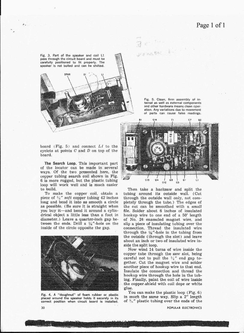
Fig. 3. Part of the speaker and coli 11pass through the circuit board and must becarefully positioned to fit properly. Thespeaker is 110t bolted and can be shifted.
board (Fig. 5j and connect £1 to theeyelets at points C and D on top of theboard.
The Search loop. This important partof the locator can be made ill severalways. Of tile two pr¢'!:Jelite~here, thecopper tubing search c'oil shown in Pig.S is more rugged, but the ,plastid tubingloop will work well !;Ina:t6 much easiert«) build.
'1'0 make the copper coil. obtain apiece of 11.1" soft copper tubing 42 incheslong and bend it ,intp as smooth a circleas possible. (Be sure it is straight whenyou buy it-and bend it lU'o~md a cylin-drical object a little less than a foot indiameter.} L~ .a ,quatt~ ...inch .gap .ee-tween the ends, Drill a :!h/l.hoie on theinside of the circle opposite the gap.
Fig. 4. A "doughnut" of ~ rubhe! O~ plasticplaced around the speaker holds it securely in itscorrect position when circuit board is installed.
30
Page 1 of1
Fig. '5. 'CieMl, firm ass!1m:bly of irt-ternat as well as external componentsand other nardware means clean oper·ation. Any variations due to movement01 parts can cause false rM!Jings.
Tben take a bac:ksaw and split thetubing around its outside wall. (Cutthrough the outside wall only. not com-pletely thrOUgh the tube.) The edges ofthe cut can be smoothed with a smalffile. SpIder about 6 inches of insulatedhookup wire to one end of a. 50' length,of No. U ...enameled :magnet wir-e, andslip a piece of Insulating tubing over the'connection. Thread the insulated wirethrough the %tq~.()lein the tubing fromthe oiltai«e (through the slot) and leaveabout an inch or two of insulated wire in-side the split loop.
Now Whld 14 turns <l! wire inside thecopper tube through the saw slot, beingcareful not to pull the YI" end gap to"-gether, Cut the magnet wire and solderanother piece: of hookup 'wire to that end.Insulate the connection and thread thehookup wire through the hole in the tub-ing.li'iJUtUYt paint the coil of wilee mside'the coppershteld with coil dope or whiteglue.
You can make the plastic loop (Fig. 6)in much the same way. Slip a 2"'~lengthof %1' plastic tubing over the ends of the
POPULAR elECTRONICS
~- ....... .. - ~ . - - -- -.,.- ~ .,..-....~-~ ~ -- ~'<-.-- -- - -~~--~ -- - ,- - --

Page 1 of 1
1I1'P~QX_~~--12"'-~---
SAW 5101 MIOUNOOlJTSltiE OF" HHlln<>
fig, 6. Loop hQ.t:Jsing made of copper fS shownabove, aM plastic: tUb-IJli{':attight, above. If plastic Isused, a metal duter-coviiril'lg can be made from alu-minum foil. In either Case. there must be a gap.
L~I" plastic tubing to hold the ends inplace. 'l'hen cut or dtil1 a hole on the In-side of the loop opposite the gap, andsplit the outside of the loop with a knife.Cut out a VII;" strip all the way aroundthe outside.
Make up the magnet wire as describedfor the copper loop and wind the searchloop with 14 turns. Cement the turns to-gather. Since the plasti.c loop does notshield the coil-as does the c-opper loop·-it must be shielded before mounting.
You, shield the plastic. loop by cuttinga piece about ;}~"wide from the end of aroll of aluminum foil. Stick the foil to apiece of Vi" plastic masking tape, leav-ing a border on each side. 'then strip theinsulatiol'l off of about half of a 6i( pieceof st'randed hookup wire, and. placethe hare portion between the foil and
Fig. 7, Plastic-covered loop must be secufely posi-ttoned. Use p.lastic cable clamps and putty or ceoment to hold the entire loop on the plywood board.
July. 1967
/lPPR(}X(ifiiil ...... ----12··,_-----
CUT 5\;OT AF!OUr~Ooutslor Of rUSING
tape at the beginning of the spiral 1.'011.Now, star-ting at the point where the
connections come out of the loop, spiral-\Vrap the tape-foil sandwich around thecoil form. When you have gam'! all theway round, tear the foil off and go round
Completed "Beacnccmber" is ready to "took tor"buried treasure. Adjust loop so it is parallel to theground whfle you hold unit at comfortable angle.
31
~ .... - - -- -~__ __ y - _ _ _ _ __ _" • ~_ - _'~r.~' _-=:.._ ,- ., _ < =_ '" ~ ~>'7~' -

The copper tubing loop assembly is rigid enough topermit the use of a small wood brace for assembly.Someweight reduction can begained in this manner.
again with the masking tape only, tohold everylhing firmly in place. Note thatthe foil mllst not form, (l, continuous loop.Do not let the end of the foil-where youstop-touch the beginning of the wind-ing.
The finished loop is mounted with plas-tic cable clamps to a %" plywood base(see Fig. 7). Use at least four clamps.The plastic loop must be potted in placeon the plywood base with water puttyto make sure it won't move or bend.
Finishing Touches. The handle on theBeachcomber can be any convenientlength of %/# aluminum tubing. and itcan be fastened to the plywood base witha universal elbow made for ;~~I"tubing.(These items were obtained by the au-thor of[ a "do-it-yourself" rack in a localhardware store. If you have trouble find-ing them, the handle can be made ofwood. Even an old hoe handle will do.)
Connect the two ends of the loop tothe two wires and the shield to the shieldbraid of a two-conductor shielded cablelong enough to run up the handle to thecontrol box. Screw the bottom of the boxto the handle and bring the cable througha hole in the bottom of the box to athree-lug terminal strip, which can bemounted with one of the screws thathold the box to the handle.
Connect circuit board points A and Bto the loop wires at the terminal stripwith about 3 to 4 inches of hookup wiretwisted toget-her. Clip in the battery, putthe box together, and you're ready to go.32
Page 1 of 1
Using the Detector. The Beachcomberis simple to use and-with a little prac-tice-you should be able to tind buriedmetal easily. The first thing to do is toset the tuning control. to produce a beatnote. Since the adjustment range of Utecoil is very wide, you should be able toget a beat note even if your search coilis not identical to the one shown.If you are not sure whether the circuit
is operating, hold a transistor radio nearthe detector while you turn the tuningcontrol. You should be able to get astrong signal near the low end of thebroadcast band somewhere in the tuningcontrol's range.
Place the search loop flat on the groundand adjust the tuning to give a low beatnote. Raising the loop 4 to 6 inches.,
,0'/APPkOKIIoU[ SENSITIV,TY
0' II£ACtlCOMOEIIUf OAMP SOIL
Fig. 8. When loop is on ground surface. you canpinpoint an object within 2 square inches. As loopis raised abOveground. it will cover a wider area:about 50 square Inches at a height of 12 inches.100 square inches at a height of 16 inches, etc.
above ground should not change the beatnote very much. To search, you simplyhold the coil near the ground and swingit from side to side, parallel to theground. If you heal' a change in thepitch of the beat note, move the coilslowly around the area to get an idea ofthe exact location and size of your find.
The change in beat note will dependon the size of the buried object and itsarea as seen from straight above. Thus.while you can easily find a coffee canlid buried tlat, you might miss it if itwere buried on edge. Figure 8 shouldgive you a good idea of the results youcan expect with the detector,
(Continued. on page 84)
POPULAR ElECTRQNIC;~
- - - - - - - - _- ~ - - - - ~