page lighti | preface€¦ · page i | preface . u.s. u.s. drive . highlights of technical...
TRANSCRIPT

Page i | Preface Light

Page i | Preface
U.S. U.S. DRIVE Highlights of Technical Accomplishments Overview Through precompetitive collaboration and technical exchange, U.S. DRIVE accelerates the development of energy-efficient advanced automotive and energy infrastructure technologies.
U.S. DRIVE (Driving Research for Vehicle efficiency and Energy sustainability) is a voluntary government-industry partnership focused on precompetitive, advanced automotive and related infrastructure technology research and development. Partners are the United States Department of Energy (DOE) and leaders in the automotive industry (United States Council for Automotive Research LLC, the collaborative technology company of FCA US LLC, Ford Motor Company, and General Motors); energy industry (BP, Chevron, Phillips 66, ExxonMobil, and Shell); and electric utility industry (DTE Energy, Southern California Edison, and the Electric Power Research Institute).
The Partnership benefits from a history of successful collaboration across multiple technical areas, each focused on a key area of the U.S. DRIVE portfolio (see below). These teams convene the best and brightest scientists and engineers from across the Partnership to discuss key technical challenges, identify possible solutions, and evaluate progress toward goals and targets published in technology roadmaps. By providing a framework for frequent and regular interaction among technical experts in common areas of expertise, U.S. DRIVE accelerates technical progress, helps to avoid duplication of efforts, ensures that publicly-funded research delivers high-value results, and overcomes high-risk barriers to technology commercialization.
U.S. DRIVE teams selected the highlights in this document from many hundreds of DOE-funded projects conducted by some of the nation’s top research organizations. Each one-page summary represents what Partnership experts collectively consider to be significant progress in the development of advanced automotive and infrastructure technologies. The report features technical highlights in two general categories:
Vehicles • Advanced Combustion and Emission Control • Electrical and Electronics • Electrochemical Energy Storage • Fuel Cells • Hydrogen Storage • Materials
Infrastructure and Integration
• Fuels • Grid Interaction • Hydrogen Codes and Standards • Hydrogen Delivery • Hydrogen Production • Integrated Systems Analysis • Vehicle and Mobility Systems Analysis
More information about U.S. DRIVE, including prior-year accomplishments reports and technology roadmaps, is available on the DOE (https://www.energy.gov/eere/vehicles/us-drive) and USCAR (www.uscar.org) web sites.

Page ii | Preface
Table of Contents
VEHICLES .......................................................................................................................................... 1
Advanced Combustion and Emission Control ....................................................................................... 1 Cavitation in Diesel Injectors is Linked to Nozzle Geometry and Quantified with X-Rays ...............................2 Quantifying the Effects of Real-World Injector Geometry on Spray Atomization .............................................3 Heat of Vaporization and Octane Sensitivity Effects on Knock-Limited Spark Ignition Engine Performance ..4 Co-Optima Blendstocks for Spark Ignited Engines Have Minimal Impact on Catalyst Light-off in Fuel Blends ...................................................................................................................................................5 Lean Gasoline Emissions Control Approach Demonstrates Fuel-Efficient Pathway to Tier 3 Target..............6 New Durable Passive Nitrogen Oxides Adsorber Shows Theoretical Maximum Palladium Utilization............7 New Catalyst Exhibits the Elusive Combination of Low Temperature Activity and High Temperature Durability ...........................................................................................................................................................8 Ducted Fuel Injection Enables Simultaneously Lower Diesel Soot and Nitrogen Oxides Emissions ..............9
Electrical and Electronics .................................................................................................................... 10 Characterization and Model for Electric Machine Lamination Materials and Interfaces................................ 11 U.S. DRIVE Develops New Cooling Technology to Enable a 100 kW/L Inverter .......................................... 12 Novel Wireless Electric Vehicle Charging Architecture Enables Compact Cost-Effective Wireless Chargers ....................................................................................................................................................................... 13 Open Source Modeling Tool OeRSTED Facilitates High Throughput Optimization of Electric Motors ........ 14
Electrochemical Energy Storage ......................................................................................................... 15 Anode Stabilization Improves Cathode Power and Life ................................................................................ 16 High-Voltage Lithium-Ion Cell with Improved Life via a Fluorinated Electrolyte ............................................ 17 Improved Lithium-Ion Cell Life via Electrolyte Additives ................................................................................ 18 Insights on Stabilizing Nickel-Rich, NMC Cathodes ...................................................................................... 19 Cycle Life Advancement Achieved in a Lithium-Metal Pouch Cell with High Energy Density ...................... 20 Synthesis of Next-Generation Lithium-Ion Cathodes by Design ................................................................... 21 High-Energy, Long-Life Lithium-Ion Battery .................................................................................................. 22 Microstructure Model Explains Battery Fast Charge ..................................................................................... 23 Significant Cycle Life with Pilot Pouch Cells Comprising NMC 811 Aqueous-Processed Cathodes ............ 24 Development of an Extreme Fast-Charging Battery ...................................................................................... 25 Stable Lithium-Metal Electrodes Enabled by Atomic Layer Deposition Sealed Three-Dimensional Hosts .. 26 Higher-Rate Solid-State Lithium-Metal Batteries ........................................................................................... 27 Development of Low-Cobalt Cathodes for Next-Generation, High-Energy-Density Lithium-Ion Batteries ... 28 High-Loading, Lean-Electrolyte Lithium-Sulfur Cells ..................................................................................... 29 Cells Fabricated with Recycled Cathode Powder Demonstrate Excellent Cycling Behavior ........................ 30
Fuel Cells ............................................................................................................................................. 31 Highly Efficient and Durable Fuel Cell Catalyst ............................................................................................. 32 High Power Durable Membrane Electrode Assembly Exceeds Performance Targets ................................. 33 New Intermetallic Catalysts Meet Durability Targets ..................................................................................... 34 Electrospun Electrode Fabrication Improves Performance and Durability .................................................... 35 Characterizing State-of-the-Art Fuel Cell Materials ....................................................................................... 36
Hydrogen Storage ............................................................................................................................... 37 Improving the Kinetics and Thermodynamics of High-Capacity Complex Metal Hydrides ........................... 38 Low-Cost High-Strength Carbon Fiber for Composite Overwrapped Pressure Vessel Applications ............ 39
Materials ............................................................................................................................................. 40

Page iii | Preface
Integrated Computational Materials Engineering Development of Carbon Fiber Composites for Lightweight Vehicles ......................................................................................................................................................... 41 Development and Integration of Predictive Models for Manufacturing and Structural Performance of Carbon Fiber Composites in Automotive Applications ............................................................................................... 42 Advanced Characterization of Magnesium Coatings .................................................................................... 43 Close Proximity Electromagnetic Carbonization............................................................................................ 44 Thin, Advanced High-Strength Steel with Carbon Fiber Reinforced Polymer Coating ................................. 45 Joining Core Program Established as Multi-Lab Partnership ........................................................................ 46 Low-Cost Magnesium Extrusion via Shear Assisted Processing and Extrusion (ShAPE™) ........................ 47 Metal Matrix Composite Brakes Using Titanium Diboride ............................................................................. 48 Low-Cost Magnesium Sheet Component Development and Demonstration Project.................................... 49
INFRASTRUCTURE AND INTEGRATION ............................................................................................. 50
Grid Interaction ................................................................................................................................... 50 120 kW Wireless Charging Enables Convenient Fast Charging of Electric Vehicles ................................... 51 Customer Preference-Enabled Workplace Vehicle Charging with Building Integration ................................ 52
Hydrogen Codes and Standards .......................................................................................................... 53 New Standards Developed for Hydrogen Compatibility of Polymeric Materials in the Infrastructure ........... 54
Hydrogen Delivery ............................................................................................................................... 55 Electrochemical Hydrogen Compressor ........................................................................................................ 56 Wireless, High-Accuracy Hydrogen Dispensers ............................................................................................ 57
Hydrogen Production .......................................................................................................................... 58 Platinum-Free Catalyst Outperforms Platinum for Microbial Electrolysis Hydrogen Production ................... 59
Integrated Systems Analysis ............................................................................................................... 60 Automated Vehicles Can Reduce Greenhouse Gas Emissions by up to 50% ............................................. 61 Battery Manufacturing and Charging Infrastructure Support Widescale Electric Vehicle Use without Major Grid Impact .................................................................................................................................................... 62

VEHICLES
Advanced Combustion and Emission Control

Page 2 | Advanced Combustion and Emission Control Technical Team
2018 U.S. DRIVE Highlight
Cavitation in Diesel Injectors is Linked to Nozzle Geometry and Quantified with X-Rays Cavitation damages fuel injectors and impacts engine performance. Recent measurements can enable the design of injectors capable of higher pressures and improved performance over an engine’s lifetime.
Argonne National Laboratory
Cavitation is an important phenomenon in fuel injectors that can lead to nozzle damage, decrease performance, and increase exhaust emissions over the life of the engine. Modern injectors are designed to suppress cavitation, but this has been achieved using slow, expensive trial-and-error, because cavitation is poorly understood. As engine designers demand ever-higher pressures from their fuel injection systems, the problems of cavitation are becoming more critical.
Researchers at Argonne National Laboratory have tracked the process of cavitation formation inside a diesel fuel injector and quantified its impact on fuel distribution outside the injector. First, researchers captured high precision measurements of the injector geometry using X-ray tomography (Figure 1). Next, high-speed X-ray imaging revealed streams of cavitating fuel emerging from the sharpest corner inside the injector. As the fuel passed over this sharp corner, a low-pressure region was formed, causing the fuel to cavitate. Finally, time-resolved X-ray
tomography of the spray quantified the density distribution of the fuel as it emerged from the nozzle and mixed with the ambient air. This highly accurate (±3%) measurement revealed that cavitation inside the nozzle generated a highly asymmetric fuel spray, with a low-density region corresponding to the location of strongest cavitation.
These capabilities represent a significant advance in injection research. For the first time, measurements reveal a complete picture of cavitation, from its geometric inception, flow through the injector, and its manifestation in the external spray. Typically, cavitation simulations are tested against data acquired in oversized plastic nozzles at lower pressures. These in situ data allow cavitation models to be tested at engine-relevant conditions and will lead to a better understanding of cavitation in fuel injectors. This accomplishment can enable the design of injectors capable of higher pressures and improved performance, improving efficiency and reducing emissions over the engine’s lifetime.
Figure 1. High-precision X-ray tomography reveals the internal geometry of the injector (left), while X-ray imaging (center) captures the bright signature of cavitation being produced by the sharp inlet corner and continuing downstream. This region of cavitation persists to the nozzle exit, and causes a low-density region in the fuel distribution (right) just outside the nozzle.

Page 3 | Advanced Combustion and Emission Control Technical Team
2018 U.S. DRIVE Highlight
Quantifying the Effects of Real-World Injector Geometry on Spray Atomization High-resolution measurements combined with high-fidelity computational simulations show that fine details of fuel injector geometry have a significant impact on fuel and air mixing.
Argonne National Laboratory
Typical production fuel injectors deliver fuel into an engine cylinder through orifices with diameters on the order of the width of a human hair. While the injectors are carefully designed with tight tolerances, the manufacturing process can result in deviations from the intended geometry. This can cause unexpected spray behavior and non-optimal fuel distribution and combustion.
Until recently, simulations of fuel flow inside injectors relied on approximations of the internal geometry, using either the manufacturer’s nominal geometry or X-ray measurements with spatial resolution of 10 micrometers at best. This is insufficient for high-fidelity simulations, which can simulate injector features down to only a few micrometers, and leads to uncertainty when comparing high-fidelity simulations with experimental measurements using real injector nozzles.
New experimental facilities at Argonne National Laboratory (ANL) can capture the three-dimensional internal geometry of fuel injectors with spatial resolution better than two micrometers. Computational meshes constructed from these X-ray data provide modelers with more realistic boundary conditions for benchmarking internal and near-nozzle spray simulations.
Using the realistic injector geometry, ANL performed high-fidelity computational fluid dynamics simulations (shown in Figure 1) to investigate the effects of injector geometry on the spray atomization process for a gasoline direct injection nozzle. Simulations included both internal nozzle flow and the external spray with micron-level computational resolution, and compared manufacturer’s nominal geometry with the realistic geometry. The numerical results indicate that the
surface details of the manufacturing process have a significant impact on fuel injection. Researchers observed changes in several spray features, including the spray morphology, Sauter mean diameter, injector tip wetting, and mass flow rate. Liquid penetration was slower, the spreading angle was wider, and breakup was earlier when utilizing the real geometry.
These results demonstrate that high-resolution injector measurements paired with high-fidelity computational simulations can improve predictions of fuel injection. Better simulations of injection and combustion will speed the development of advanced combustion engines, enabling increased energy efficiency while protecting the environment.
Figure 1. Comparison of injector geometry and spray simulations using nominal (left) and measured (right) injector geometries. High-fidelity simulations showed that utilizing the real-world geometry had a significant impact on the spray atomization process.

Page 4 | Advanced Combustion and Emission Control Technical Team
2018 U.S. DRIVE Highlight
Heat of Vaporization and Octane Sensitivity Effects on Knock-Limited Spark Ignition Engine Performance Separating chemical versus thermal effects provides greater understanding of how fuel knock resistance enables increased engine output for greater efficiency.
National Renewable Energy Laboratory
A recently completed engine research study focused on separating fuel knock resistance in terms of chemical versus thermal effects. Evaporative cooling is known to increase fuel knock resistance with direct injection (DI) versus port fuel injection in spark ignition gasoline engines. For hydrocarbon fuels, a research octane number (RON) increase of 3-5 units allows the engine compression ratio to be increased by ~1 unit. Studies also show additional charge cooling for high heat of vaporization (HOV) ethanol fuel blends. Yet there are conflicting results on whether this increases knock resistance: when octane sensitivity (S) and HOV are covariant, knock resistance increases; when S is constant, higher HOV does not increase knock resistance.
Researchers investigated knock-limited (KL) loads for a set of surrogate gasolines with nominal 100 RON, ~11 S, and an HOV range of 390 to 595 kJ/kg in a research single cylinder engine at various intake air temperatures (IATs) (Figure 1). The team used two fuel systems, DI and pre-vaporized upstream injection (UI) supplied by a fuel injector mounted far upstream of the intake valves, to separate chemical and thermal effects of fuel knock resistance. The study highlights how fuel HOV can affect the temperature at intake valve closing, and consequently the pressure-temperature history of the end gas leading to more negative values of K (where octane index [OI] = RON – K * S), thereby enhancing the effect of S on knock resistance at beyond RON conditions. For downsized boosted engines, K is negative at the most KL operating conditions, such that increasing S increases OI.
The results show that within the constraints of OI theory K is not only a function of engine design and operating conditions, it can also be affected by a fuel property. High HOV fuels (i.e., alcohols) increase
charge cooling, making K more negative relative to hydrocarbon fuels. Reanalyzing the literature data suggest that with high HOV fuels, which reduce intake valve closure temperature (IVCT) relative to hydrocarbon fuels, an incorrect assumption of K = 0 in the RON test is the source of how HOV acts as a thermal component of S. For DI engines, HOV reduces IVCT which can significantly reduce K, enhancing the positive impact of S on knock resistance for beyond RON conditions. Fuels with higher HOV, such as ethanol blends, will therefore have lower values of K, all other factors being equal.
Figure 1. Knock-limited IAT sweep results from DI and UI modes at 1,500 revolutions per minute with the crank angle where 50% of heat is released held constant at 20.5° after top dead center. Fuel HOV values shown are for 25°C. Figure from SAE Technical Paper 2018-01-0218, 2018, doi:10.4271/2018-01-0218.

Page 5 | Advanced Combustion and Emission Control Technical Team
2018 U.S. DRIVE Highlight
Co-Optima Blendstocks for Spark Ignited Engines Have Minimal Impact on Catalyst Light-off in Fuel Blends Fuels containing 10% to 30% of Co-Optima blendstocks for spark ignited engines should not have a significant impact on three-way catalyst performance during cold start.
Oak Ridge National Laboratory
The U.S. Department of Energy’s Co-Optimization of Fuels and Engines (Co-Optima) initiative aims to simultaneously transform both transportation fuels and engines to maximize performance and energy efficiency. New fuels and engines must still meet emissions regulations to be commercially viable, which is why enabling compliance with U.S. Environmental Protection Agency Tier 3 emissions regulations is a U.S. DRIVE goal. Because nearly all of the tailpipe emissions from boosted spark ignited (SI) engines occur during cold start before the emissions control catalysts are functional, fuel formulations that change the light-off temperature of the catalyst could impact emissions compliance for both NMOG (non-methane organic gases, mostly unburned fuel) and oxides of nitrogen (NOx). This is because NOx conversion requires consumption of all unburned fuel species in engines with a stoichiometric air/fuel ratio.
Researchers at Oak Ridge National Laboratory (ORNL) have been measuring the catalytic light-off performance of fuel blends containing 10% to 30% by volume of the most promising Co-Optima fuel components mixed into a surrogate blendstock for oxygenated blending (BOB). These fuel components were identified as having favorable fuel properties that would enable advanced engines to meet the U.S. DRIVE efficiency targets. While the pure Co-Optima fuel components have significantly different light-off temperatures, the fuel mixtures containing up to 30% of the components do not show significant differences in catalyst light-off.
The T90s (the temperatures at which 90% of the fuel species are converted over the catalyst) for all the blends are essentially within experimental error of each other, and there are no discernible trends with blend level (Figure 1). There are small effects of
blend composition on T50 (the temperature at which 50% of the fuel species are converted over the catalyst), and the blend trends are consistent with the pure component light-off results. Ethanol, which has a relatively low T50, reduces the blend light-off temperature. Isobutanol, the aromatics, and the alkene, which have higher T50s, increase blend light-off temperatures. However, the overall shift in T50 is only about 12°C from the least reactive to the most reactive fuel blend. This shift would not have a significant impact on overall cold start emissions. Thus, the light-off temperature is primarily determined by the BOB composition, and fuel blends containing up to 30% of the Co-Optima fuel components will likely not have a significant impact on cold start NMOG or NOx emissions for stoichiometric boosted SI engines.
Figure 1. Temperatures at which 50% (T50) and 90% (T90) of the fuel species are converted over an aged production three-way catalyst in a synthetic exhaust mixture containing: a surrogate BOB; 10%, 20%, and 30% ethanol blended into the BOB; 100% ethanol; 10%, 20%, and 30% isobutanol blended into the BOB; 100% isobutanol; 10%, 20%, and 30% of an aromatic mixture blended into the BOB; 100% aromatic mixture; 10%, 20%, and 30% di-isobutylene blended into the BOB; and 100% di-isobutylene.

Page 6 | Advanced Combustion and Emission Control Technical Team
2018 U.S. DRIVE Highlight
Lean Gasoline Emissions Control Approach Demonstrates Fuel-Efficient Pathway to Tier 3 Target Demonstration achieved using non-urea, passive selective catalytic reduction and a 6-mode pseudo-transient drive cycle with nearly 6% less fuel usage than stoichiometric operation.
Oak Ridge National Laboratory
The transition to high-efficiency lean combustion supports the U.S. DRIVE target of 20% improved fuel efficiency over current gasoline vehicles. However, lean-burn engines still must comply with U.S. Environmental Protection Agency (E.P.A.) Tier 3 emissions regulations, which is especially difficult for oxides of nitrogen (NOx) in lean exhaust. Thus, development of strategies for lean-gasoline vehicles to meet emissions regulations will enable significant efficiency improvements.
Stoichiometric gasoline vehicles rely on well-established three-way catalyst (TWC) technology to meet the emissions requirements for NOx, hydrocarbons (HCs), and carbon monoxide (CO). Vehicles with lean-burn engines, such as those that run on diesel fuel, employ a complex selective catalytic reduction (SCR) system that requires urea tanks and injectors to introduce ammonia (NH3) that reacts with NOx over the SCR catalyst. Oak Ridge National Laboratory (ORNL), in collaboration with General Motors and Umicore, is investigating a pathway that combines TWC and SCR and thus could remove the complexity and cost associated with urea tanks and injectors. In this “passive SCR” approach, NH3 is generated over the TWC during mildly fuel-rich operation and stored on the downstream SCR. The stored NH3 reduces NOx during fuel-efficient lean operation.
Using a lean-gasoline engine platform, ORNL employed a 6-mode pseudo-transient cycle to mimic the federal test protocol used to measure emissions compliance. Using the TWC+SCR “passive SCR” system to control emissions, the researchers were able to limit NOx+HC emissions to 0.03 g/mile (E.P.A. Tier 3 standard), while also showing a reduction in fuel consumption of 6% compared to stoichiometric-only operation. CO emissions were still higher than required levels and
may require the introduction of a clean-up catalyst after the SCR to meet the 1.0 g/mi standard.
Figure 1. NOx and HC emissions from a lean gasoline engine are reduced to E.P.A. Tier 3 levels, 0.03 g/mi, employing only TWC and SCR technologies in a “passive SCR” approach, while reducing fuel consumption by 6% compared to stoichiometric operation. CO levels remain above the standard and will be the focus of future research.

Page 7 | Advanced Combustion and Emission Control Technical Team
2018 U.S. DRIVE Highlight
New Durable Passive Nitrogen Oxides Adsorber Shows Theoretical Maximum Palladium Utilization Palladium/SSZ-13 zeolites are shown to be high-performance passive nitrogen oxide and carbon monoxide adsorber materials exhibiting attractive uptake and release characteristics.
Pacific Northwest National Laboratory
Improved low-temperature and cold-start exhaust aftertreatment strategies are necessary to further reduce criteria pollutant emissions and enable widespread deployment of advanced combustion strategies in transportation. This is described in the 150°C grand challenge, which tasks researchers developing aftertreatment technologies to achieve a greater than 90% emission reduction at less than 150°C, to enable the Tier 3 Bin 30 limit of 30 mg/mile of non-methane organic gases (NMOG) + oxides of nitrogen (NOx) by 2025. This presents a significant challenge to low-temperature NOx removal due to the ≥200°C required for current ammonia (NH3) selective catalytic reduction (SCR) technology to be effective, and ≥180°C required for urea dosing to supply the critical SCR reductant. To meet these regulations, low-temperature passive NOx adsorber (PNA) materials have been developed, including Johnson-Matthey’s palladium (Pd)-loaded zeolites. These materials need to be advanced to improve expensive Pd utilization and optimize NOx release characteristics.
Pacific Northwest National Laboratory (PNNL) has developed a facile and scalable method of PNA synthesis that introduces atomically dispersed Pd(II) ions into small-pore zeolites (SSZ-13). This method allows for maximum Pd utilization (nitric oxide [NO]/Pd = 1) at up to 2 wt% Pd loading. The resulting PNA exhibits unrivaled NOx storage capacity, complete removal of NOx for more than 1.5 minutes, and attractive release characteristics (Figure 1). Therefore, PNNL’s PNA is a critical technology that, when combined with a NOx conversion catalyst, enables near-complete cold-start NOx abatement that is unrivaled when compared with current technology. PNNL found that the PNA technology functions through formation of a mixed complex that involves both NO and carbon
monoxide (CO), thus providing efficient NO and CO abatement simultaneously. This complex is largely responsible for the superior performance of these PNA formulations in the presence of CO and water vapor. Furthermore, research has revealed that only select Pd cations are PNA active under practical exhaust conditions, which are achieved by the PNNL synthesis method. Even in the presence of water vapor, the active Pd cations are durable due to the reversible formation of the CO-NO Pd(II) complex. The resulting PNA exhibits near-optimum performance by providing atom-economy efficiency (with essentially each Pd atom utilized) in a manner that is durable to hydrothermal aging at 750°C/16 hours and durable to sulfur exposure.
Figure 1. PNA performance showing excellent capacity and release characteristics of Pd SSZ-13.

Page 8 | Advanced Combustion and Emission Control Technical Team
2018 U.S. DRIVE Highlight
New Catalyst Exhibits the Elusive Combination of Low Temperature Activity and High Temperature Durability Catalyst activated by steam treatment under harsh conditions is a promising and novel approach that demonstrates progress towards overcoming “The 150°C Challenge.”
Pacific Northwest National Laboratory, Washington State University, and the University of New Mexico
Future combustion engines are expected to have lower exhaust temperatures that require aftertreatment catalysts that are both active at low temperatures and durable at high temperatures in engine exhaust. This is described in the 150°C grand challenge, which tasks researchers developing aftertreatment technologies that achieve greater than 90% emission reduction at less than 150°C, and collectively is necessary to enable the Tier 3 Bin 30 limit of 30 mg/mile of non-methane organic gases + nitrogen oxides (NOx) by 2025.
For carbon monoxide (CO) and hydrocarbon (HC) oxidation, platinum group metal (PGM)-based catalysts are currently applied. However, zero-valent PGMs are notoriously mobile at high temperatures and tend to agglomerate towards larger particles, resulting in a loss of catalytic activity. Although several promising candidate materials and substrates have been previously reported, the combination of low-temperature activity and high-temperature durability remains a challenge.
Pacific Northwest National Laboratory (PNNL) researchers, together with collaborators from Washington State University and the University of New Mexico, have discovered a platinum (Pt)-based catalyst that exhibits the elusive combination of low-temperature activity and high temperature durability. The catalyst is atomically-dispersed ionic Pt2+ on Pt/cerium(IV) oxide (CeO2), and is activated via a steam treatment process at 750°C. The synthesis involves a novel approach to trap and stabilize Pt atoms on a CeO2 surface, resulting in atomically-dispersed Pt that enables more efficient and economical use of the precious metal. The catalyst is subsequently treated in high-temperature (750°C) steam to result in a CeO2 catalyst that is
thermally-stable even under harsh hydrothermal conditions.
Work has demonstrated stable low-temperature CO oxidation activity (see Figure 1) without detrimental impact from other pollutants (e.g., hydrocarbons and NOx) and significantly reduced impact from sulfur exposure (compared to conventional CeO2-based materials systems). Activated lattice oxygen, acquired via steam treatment, is believed to be responsible for the extraordinary activity. Ultra-high resolution imaging confirms atomic dispersion of Pt that is retained after 800°C hydrothermal treatment.
Figure 1. CO oxidation light-off performance showing excellent low-temperature activity and stability of the hydrothermally-treated Pt/CeO2 catalyst under exhaust conditions.

Page 9 | Advanced Combustion and Emission Control Technical Team
2018 U.S. DRIVE Highlight
Ducted Fuel Injection Enables Simultaneously Lower Diesel Soot and Nitrogen Oxides Emissions New technology shows promise for enabling high-efficiency engines that are cleaner and less costly.
Sandia National Laboratories
Ducted fuel injection (DFI), a concept invented at Sandia National Laboratories (SNL), involves injecting each diesel fuel spray down the axis of a small cylindrical duct within the combustion chamber. The left side of Figure 1 shows a rendering of DFI with two ducts in an engine. The main objective of DFI is to achieve more-uniform local fuel/charge-gas mixtures where combustion occurs, at or beyond the downstream end of each duct, thereby attenuating soot formation. Previously, DFI has been shown to curtail diesel soot formation by an order of magnitude or more in combustion-vessel experiments.
SNL conducted the first DFI experiments in an engine in fiscal year 2018, to determine the impacts of DFI on engine performance, including emissions, efficiency, and heat-release rate. The two-duct
configuration shown in Figure 1 was tested at a 1,200-rpm, light-load condition. The results indicate that DFI can lower soot by approximately an order of magnitude relative to conventional diesel combustion (CDC) at constant intake-mixture dilution, as shown in Figure 1 right. The results also show that when combined with intake-mixture dilution, DFI oxides of nitrogen (NOx) and soot emissions simultaneously decrease, breaking the long-standing diesel soot/NOx trade-off with dilution. This is achieved without significant degradation in other emissions or efficiency; hence, it could enable higher efficiency due to lower aftertreatment-system backpressure and longer regeneration intervals. DFI also preserves the simple control of ignition timing and the inherent fuel-flexibility of CDC, both of which facilitate the broader use of renewable fuels.
Figure 1. Left: DFI with two ducts as implemented for the first-ever testing in an engine. Right: Comparison of indicated-specific (IS) engine-out emissions of soot and NOx for CDC versus DFI, as a function of intake-mixture dilution (i.e., oxygen mole fraction, mol% O2). DFI with dilution enables lower combined soot and NOx levels than CDC. Results shown were obtained using a commercial diesel fuel.

Electrical and Electronics

Page 11 | Electrical and Electronics Technical Team
2018 U.S. DRIVE Highlight
Characterization and Model for Electric Machine Lamination Materials and Interfaces Rigorous experimental characterization and model for electric machine lamination stack thermal resistance helps reduce design iterations in advanced motor designs.
National Renewable Energy Laboratory
Thermal models of electric motors, such as finite element and computational fluid dynamics models, are becoming increasingly sophisticated and are being utilized earlier in the design process; however, the modeling efforts are dependent on accurate material properties and data for material interfaces such as thermal interface resistance. The limited information in open literature detailing the thermal properties of key materials common in electric machines creates challenges in simulating new or innovative motor designs. The lack of available literature, coupled with the strong interest from industry, led to this work to characterize and model the thermal contact resistance between machine laminations.
Silicon steel lamination materials are critical in the construction and operation of systems including inductors for power systems and electric motors. Thinner laminations decrease core losses within the lamination stack but increase the number of contacts and consequently the thermal resistance within the stack. The increased number of contacts or interfaces between laminations impacts the effective thermal conductivity through the stack of laminations, influencing the temperature distribution within the motor assembly.
The thermal conductivity of the lamination stack is orthotropic, as shown in Figure 1(a). Thus, it was important to determine effective properties for both the in-plane (shown in Figure 1(a) as the x-y plane) and through-stack direction (shown in Figure 1(a) as the z direction). The National Renewable Energy Laboratory (NREL) developed a procedure to experimentally characterize layered materials (Figure 1(b)), and applied the technique to silicon steel laminations. NREL measured data for different lamination materials ranging in thickness from
0.178 mm to 0.47 mm and with different surface topologies. Using the experimental results, NREL developed a model that provided a good prediction for the interlamination contact resistance and the through-stack thermal conductivity (Figure 1(c)). The work was recently published in the International Journal of Heat and Mass Transfer (“Experimental Characterization and Modeling of Thermal Resistance of Electric Machine Lamination Stacks,” vol. 129, pp. 152–159, Feb. 2019).
These results fill a current need for material property data and models specific to electric machine design that currently do not exist in the public/open literature. The data and modeling approach is especially useful for simulating heat extraction axially through the lamination materials within the machine, which is particularly important for cooling rotors used in permanent-magnet machines.
Figure 1. (a) Orthotropic thermal property orientation for machine laminations. (b) Photo of experimental setup (Photo Credit: Emily Cousineau, NREL). (c) Results predicted by the model compared to the experimental data for one example sample material.

Page 12 | Electrical and Electronics Technical Team
2018 U.S. DRIVE Highlight
U.S. DRIVE Develops New Cooling Technology to Enable a 100 kW/L Inverter Innovative cooling concept is predicted to improve thermal performance and enable achieving the 2025 power density target of 100 kW/L.
National Renewable Energy Laboratory
The U.S. DRIVE Electrical and Electronics Technical Team (EETT) Roadmap proposes aggressive research targets to improve power electronics technology to support the mass-market penetration of electric drive vehicles. Achieving these aggressive targets will require a significant increase in power density (2025 EETT power density target: 100 kW/L) as compared with current, on-road technology. The National Renewable Energy Laboratory (NREL) has been working to develop innovative thermal management solutions to achieve this aggressive target.
Through thermal and computational fluid dynamics (CFD) modeling, NREL has developed a novel power electronics cooling concept that is predicted to enable achieving the 100 kW/L power density target. The cooling concept is unique (i.e., not used in automotive cooling systems) and is predicted to provide better thermal performance as compared with current automotive technology (~50% lower thermal resistance than the on-road technology). Submerged dielectric fluid jets impinging on highly dense finned structures are used to cool a planar module via single-phase heat transfer (Figure 1). The planar module design eliminates layers to reduce package/conduction thermal resistance but requires using a dielectric fluid because the fluid is in direct contact with electrically-active surfaces. The cooling concept and planar module design also eliminate the need for thermally conductive ceramics (e.g., silicon nitride), which are expensive and prone to thermomechanical failures, especially at high-temperature conditions (≥ 200°C). An added benefit of the cooling concept is the ability to directly cool the electrical interconnections, which will decrease capacitor and gate driver temperatures and enable more compact packaging (high power density).
Thus far, EC-140 and Alpha 6 dielectric fluids have been used for the modeling design work. Both dielectric fluids have relatively high flash point temperatures, are safe (nontoxic, environmentally friendly), and have good material compatibility. However, NREL plans to evaluate using automatic transmission fluid (ATF) as the dielectric coolant to decrease cost, allow for using an automotive-grade fluid, and enable integration of the power electronics with the electric motor.
NREL performed extensive CFD simulations to optimize the fin structures (Figure 1) and to design the electrical interconnect cooling system. Future work includes modeling the effect of multiple dielectric fluid jets cooling multiple devices, evaluating the effect of high fluid viscosity at low-temperature conditions (-40°C temperature), and evaluating the use of ATF as the dielectric coolant. Once the design (via modeling) is complete, NREL will fabricate a prototype for experimental validation of the concept.
Figure 1. CFD-computed temperatures for the 2.5-mm-tall fins configuration and jet velocity of 0.5 m/s predicted to enable reaching the 100 kW/L power density target.

Page 13 | Electrical and Electronics Technical Team
2018 U.S. DRIVE Highlight
Novel Wireless Electric Vehicle Charging Architecture Enables Compact Cost-Effective Wireless Chargers A wireless coil and a resonant capacitor are the only extra components needed to add wireless charging capability to any electric vehicle.
Oak Ridge National Laboratory
Cost-effective, convenient, and compact charging systems for battery electric vehicles (BEVs) are critical in accelerating the transition to electrified mobility. Although conventional conductive charging systems are cost-effective, they suffer from increased conductor weight as the charging power level increases and are inherently less suitable for automated charging as they require the user to physically plug-in the charger. This can be especially cumbersome in inclement weather conditions. Wireless BEV charging is a convenient alternative to plug-in or wired charging. Weight, volume, and cost of the on-board power electronic components of the wireless BEV charging system are the main challenges to increasing the appeal of wireless BEV charging systems.
The on-board components of a wireless BEV charging system include a vehicle side coil, resonant capacitor, high-frequency rectifier (and the heat sink), and a filter capacitor. Oak Ridge National Laboratory (ORNL) proposed an integrated wireless charger architecture, which utilizes the existing traction inverter and the direct current (DC) link capacitor of the electric drivetrain as the secondary side rectifier of the wireless BEV charging system (Figure 1). This leads to increased power density, specific power, and reduced cost. ORNL also designed and prototyped an optimized interoperable double D coil pair to facilitate validation of the proposed integrated wireless charging architecture. The proposed integrated wireless BEV charging architecture aligns very well with the overall Electrical and Electronics Technical Team goals that envision ways to improve the power density and cost effectiveness of on-board BEV components.
Figure 1. Schematic of the integrated wireless BEV charging architecture proposed by ORNL.
ORNL developed an 11-kW integrated wireless charging system utilizing a 2016 BMW i3 traction inverter as the secondary side rectifier of a wireless BEV charging system. Researchers also evaluated the effect of integrating the rectifier function into the traction inverter on the motor. ORNL experimentally validated the prototyped integrated wireless EV charging architecture for 12 kW operation for a coil-t0-coil gap of 165.1 mm (6.5 inches). The DC-to-DC efficiency of the integrated wireless charging system without the motor connected was 91.8% and with the motor connected was 88.96%. One of the key observations was that when the motor was connected to the traction inverter and operated as the rectifier for the integrated charger, the rotor showed no displacement and there were no signs of heating or chatter in the motor. Researchers evaluated this for different starting positions of the rotor, corresponding to different inductances as measured at the motor terminals (inverter was disconnected for inductance measurements). The worst-case measured loss of 340 W in the traction motor is a fraction of the rated capacity of the traction motor of 125 kW.

Page 14 | Electrical and Electronics Technical Team
2018 U.S. DRIVE Highlight
Open Source Modeling Tool OeRSTED Facilitates High Throughput Optimization of Electric Motors Simulation Toolkit will enable rapid design of electric motors and support achieving U.S. DRIVE 2025 power density targets of 50 kW/L.
Oak Ridge National Laboratory
Designing high power density, low-cost electric motors with excellent reliability and long lifetimes requires optimizing drive systems to push the boundaries of feasibility. Because electric motors are geometrically complex multi-material systems, the amount of computational resources required to explore spaces consisting of dozens or even hundreds of design variables are staggering. Motor lifetime, reliability, and cost are strongly influenced by strict thermal and efficiency constraints and require precise magnetic material models to evaluate accurately within a simulation environment.
To meet the 2025 Electrical and Electronics Technical Team goals for electric motors, Oak Ridge National Laboratory (ORNL) has begun developing an open source high-performance computing toolkit for electric motor modeling and optimization, the Oak Ridge Toolkit for Electromagnetic Devices (OeRSTED). The toolkit is scalable from workstations to the U.S. Department of Energy’s first-class high-performance computing (HPC) resources for high-throughput optimization of electric motors. Increasing throughput is achieved by developing analysis methods for quickly characterizing motor designs on single nodes/workstations and researching new and improved evolutionary optimization methods for simultaneous analysis of multiple designs.
Identifying the efficiency map for a single motor design is important for evaluating candidate design fitness. OeRSTED has been demonstrated to achieve 30x speedup in efficiency map identification on both a workstation and a single HPC node with 32 available cores. Additionally, ORNL developed and demonstrated a novel asynchronous particle swarm optimization method to achieve linear scaling up to the number of simultaneous design evaluations,
which was 40 in the largest demonstration. Combined, this represents more than a 1000x increase in optimization speed. Thus far, the speed increase has only been limited by the amount of computational resources.
OeRSTED’s standard analysis methods have been validated against existing commercial finite element software. Figure 1 shows a flux density plot generated from an OeRSTED simulation of a synchronous reluctance motor, which demonstrated excellent agreement with other simulation tools. Advanced material models under development are driven by high-fidelity characterization methods. Material models, which would otherwise be too computationally expensive to implement within a finite element analysis framework, have been made feasible through the availability of advanced computing tools. Ultimately, these techniques will provide a step change in predicting phenomena that are critical for electric motor reliability and cost, such as demagnetization of permanent magnets.
Figure 1. Magnetic flux density distribution in a 1/8th section model of a permanent magnet free synchronous reluctance electric motor simulated using OeRSTED.

Electrochemical Energy Storage

Page 16 | Electrochemical Energy Storage Technical Team
2018 U.S. DRIVE Highlight
Anode Stabilization Improves Cathode Power and Life Researchers have shown that robust anode solid electrolyte interphase can be formed electrochemically using advanced, high-voltage, fluorinated electrolytes, enabling better performance with NMC cathodes.
Argonne National Laboratory
Nickel-rich layered oxide cathodes, Li(Ni1-x-
yMnxCoy)O2 (NMC), are promising cathodes for next-generation batteries. Significantly more energy can be stored in these batteries when charged to higher voltages. However, higher charging voltages can result in increased loss of both energy and power as the battery ages. This loss is thought to originate in part due to reactions between the high-voltage NMC surface and a reactive electrolyte. In this work, a treatment of the opposite electrode (a graphite anode), showed a benefit in high voltage cycling stability with NMC-graphite batteries. The graphite anode in traditional batteries also suffers from reactions with the electrolyte, which occur predominantly during the first charge of the battery. These reactions create a protective layer, the solid electrolyte interphase (SEI), that prevents further reactions. This project explores the effect of using graphite electrodes that have had the SEI formed separately, prior to cycling, through reactions with various electrolytes; either 1.2 M LiPF6 EC:EMC (3:7), known as the Gen2 electrolyte, or FE-3, a novel highly fluorinated electrolyte. Note that this research is an SEI formation investigation.
Researchers found that changing characteristics of the graphite anode surface with this preformed coating decreases the unwanted reactions that take place on both the anode and NMC cathode. Figure 1 shows evidence of these benefits. Figure 1 Top shows the effect of the various anode coatings. Graphite preformed with fluorinated FE-3 electrolyte (FE-3 Gr) shows higher and more stable capacity. Graphite preformed with the baseline electrolyte (Gen2 Gr) does not show the same benefit. Likewise, the power performance of these batteries is improved. Figure 1 Bottom shows the resistance (which slows power delivery). The cells containing FE-3 preformed graphite show more stable performance and power
delivery over the battery life than the cells containing Gen2 preformed graphite.
The conclusion is that reactive components from the graphite anode can cause performance loss at the opposite electrode, and that a more stabilizing protective layer on the graphite can lead to better battery performance. The insights from this work are that engineered changes at the graphite-electrolyte interface can stabilize the NMC-electrolyte interface. This finding provides another pathway to stabilize this reactive NMC surface and thus enable higher energy cells in vehicle applications.
Figure 1. Top. Battery cycle life for either FE-3 formed, Gen2 formed, or pristine graphite (baseline) showing better retention for FE-3 Gr. Bottom. Power loss over the course of the cycling shown in the top for cells containing FE-3 (left) and Gen2 (right) preformed graphite showing improved power retention on left.

Page 17 | Electrochemical Energy Storage Technical Team
2018 U.S. DRIVE Highlight
High-Voltage Lithium-Ion Cell with Improved Life via a Fluorinated Electrolyte A polyfluorinated carbonate electrolyte developed as a high-voltage enabling electrolyte for next-generation high-energy density lithium-ion batteries.
Argonne National Laboratory
Designed for 4 volt (V)-class lithium (Li)-ion chemistry, conventional carbonate-based electrolytes suffer from oxidative instability at the cathode/electrolyte interface at high charging voltages, which leads to severe transition metal (TM) dissolution and rapid capacity and power fade.
Argonne National Laboratory (ANL) researchers have developed a high-voltage enabling polyfluorinated carbonate electrolyte comprised of 1.0 M LiPF6 in difluoroethylene carbonate (DFEC)/bis(2,2,2-trifluoroethyl) carbonate (HFDEC) (3/7 weight ratio, coded as FE-3). Due to its enhanced oxidative stability, the new electrolyte remains stable during the charging process and suppresses the dissolution of TMs at potentials higher than 4.4V vs. Li+/Li. This new electrolyte is also capable of forming a resilient solid electrolyte interphase (SEI) on the graphite anode surface during the first formation cycle, an indispensable property that many new electrolytes lack. The formed SEI is resistant to TM attack, yielding a reversible Li+ intercalation/deintercalation chemistry without active Li loss caused by the TM-catalyzed parasitic reactions on the anode surface.
A LiNi0.5Mn0.3Co0.2O2 (NMC532)/graphite cell showed superior long-term cycling stability at high voltages (4.6V vs. Li+/Li) when the fluorinated electrolyte was used (Figure 1(a)). Post-test analysis using inductively coupled plasma mass spectrometry indicated that the fluorinated electrolyte suppressed the dissolution of TMs (Figure 1(b)) and subsequent crossover to the anode surface (not shown), which is consistent with the material structural analysis by high-resolution transmission electron microscopy electron energy loss spectroscopy data. The three test conditions referenced in Figure 1b refer to the number of cycles that were completed before the measurement was taken.
Future work will include testing this and other fluorinated electrolytes with higher nickel (Ni) cathodes like NMC 622 and 811.
Figure 1. (a) Capacity retention and Coulombic efficiency of NMC532/graphite cells with Gen 2 and FE-3 electrolyte, and (b) TM (Ni, cobalt [Co], manganese [Mn]) dissolution at various testing conditions.
Page 18 | Electrochemical Energy Storage Technical Team
2018 U.S. DRIVE Highlight
Improved Lithium-Ion Cell Life via Electrolyte Additives Certain additives, when allowed to “age” in common electrolyte formulations, undergo chemical transformations that result in stabilization of cathodes under high-voltage operation.
Argonne National Laboratory
The energy storage system of choice for electric vehicles is the lithium (Li)-ion battery. The more energy stored in that battery, the longer the driving range. Currently, the cathode limits the maximum energy storage for Li-ion batteries. Overcoming that limitation requires cathode materials that have high capacity and operate at high voltage. While such materials have been identified, their long-term use remains problematic, because they degrade the liquid electrolyte when in contact with the energized cathode during cycling.
One well-known means of improving this situation involves inserting a performance-boosting additive in the liquid electrolyte. This additive modifies the cathode surface by forming a protective layer that stalls the electrolyte decomposition. One such common additive is tris(trimethylsilyl)phosphite (TMSPi). The mechanism behind its beneficial effect has been a mystery—until now.
The new result is that the TMSPi molecule is not involved directly in the protection of the cathode. The active component is a different molecule, PF2OSiMe3, which is chemically derived from TMSPi. PF2OSiMe3 is gaseous at room temperature and difficult to synthesize in the lab, thus in situ synthesis is critical. This compound slowly forms as the Li salt in the electrolyte reacts with TMSPi, a process that can be compared to the fermentation of cucumbers in brine that produces pickles.
The reaction product generated during this “pickling” process lessens the rise in electrical resistance that occurs in the battery during cycling. The TMPSi product also reduces the harmful loss of transition metals (typically cobalt or manganese) from the cathode and reduces the occurrence of parasitic currents that degrade the cell.
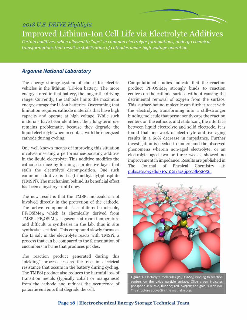
Computational studies indicate that the reaction product PF2OSiMe3 strongly binds to reaction centers on the cathode surface without causing the detrimental removal of oxygen from the surface. This surface-bound molecule can further react with the electrolyte, transforming into a still-stronger binding molecule that permanently caps the reaction centers on the cathode, and stabilizing the interface between liquid electrolyte and solid electrode. It is found that one week of electrolyte additive aging results in a 60% decrease in impedance. Further investigation is needed to understand the observed phenomena wherein non-aged electrolyte, or an electrolyte aged two or three weeks, showed no improvement in impedance. Results are published in The Journal of Physical Chemistry at: pubs.acs.org/doi/10.1021/acs.jpcc.8b02056.
Figure 1. Electrolyte molecules (PF2OSiMe3) binding to reaction centers on the oxide particle surface. Olive green indicates phosphorus; purple, fluorine; red, oxygen; and gold, silicon (Si). The structure above Si is the methyl group.

Page 19 | Electrochemical Energy Storage Technical Team
2018 U.S. DRIVE Highlight
Insights on Stabilizing Nickel-Rich, NMC Cathodes Protection layers, deposited on cathode surfaces, have long been employed to mitigate unwanted reactions that lead to cell degradation. Researchers are discovering why materials such as aluminum oxide have not so far enabled long-term, high-voltage cycling of nickel-rich NMCs.
Argonne National Laboratory
Nickel-rich, LiNi1-x-yMnxCoyO2 (NMC) cathodes, where Ni comprises more than 60%, are being developed for high-voltage applications such as electric vehicles. These materials are desirable because of their high volumetric energy and power densities. However, degradation phenomena related to surface instabilities of charged Ni-rich cathodes have been, and remain, a major concern with respect to cycle-life and safety. This is due, in part, to the difficulty of characterizing and understanding the behavior of Ni at surfaces separately from its behavior in the bulk, especially during operation of a working cell. Researchers at Argonne National Laboratory (ANL) have developed a system that allows monitoring of Ni in the near-surface regions of cathode particles during operation of a lithium (Li)-ion battery. This system was recently used to probe the efficacy of conformal aluminum oxide (Al2O3) coatings in stabilizing charged cathodes having Ni-rich surfaces.
ANL developed a synthesis method whereby Ni can be substituted into the surface of a layered cathode consisting of only Li, manganese (Mn), and cobalt (Co). Controlling conditions enabled a Ni-rich, layered, NMC structure to be integrated into the top ~20 nm of the surface of cathode particles (Figure 1(a)). This system allows the use of penetrating, hard X-rays for spectroscopy of a working cell, where signatures of Ni activity originate from surface-Ni only, giving an unprecedented look at the surface of a working cell. Figure 1(b) shows a spectroscopic image of a ~3 nm Al2O3 coating deposited by atomic layer deposition (ALD) on the model system. Figure 1(c) shows Ni spectroscopy of the Al2O3-coated system that was charged to 4.4 volt (V) (Li/Li+). The dashed line represents the charge state that Ni, residing in the bulk of an NMC particle, would reach at just 4.3V. The data collected at ~4.2-4.4V for the
coated system show that a lower state of charge is reached for surface Ni. Similar data were observed for the uncoated system, revealing that the presence of the ~3 nm, Al2O3 coating did not stabilize near-surface Ni to higher states of charge. These findings hint that these coatings do not prevent oxygen loss from surface Ni. Accordingly, this points to the need for more advanced research and new material/surface designs, including perhaps dopants to further stabilize Ni at high states of delithiation, and tailored to specific cathode compositions.
Figure 1. (a) Microscopy/spectroscopy showing layered, Ni-rich, NMC-type surfaces of the model system. (b) ~3nm Al2O3 coating. (c) In situ X-ray data revealing the difference between bulk Ni and Al2O3-coated surface Ni during charge.
25 nm
(a) (b)
Bulk Ni/no coating
Surface Ni/Al2O3
Sharifi-Asl (UIC)

Page 20 | Electrochemical Energy Storage Technical Team
2018 U.S. DRIVE Highlight
Cycle Life Advancement Achieved in a Lithium-Metal Pouch Cell with High Energy Density Battery500 Consortium achieves more than 150 charge-discharge cycles for 350 Wh/kg pouch cells.
Battery500 Consortium Team
Lithium (Li)-ion batteries are widely used for consumer electronics and electric vehicles, but it is difficult to increase the energy density beyond 300Wh/kg and reduce the cost to less than $100/kWh with today’s cell materials. The objective of the U.S. Department of Energy’s Battery500 Consortium is to develop a next-generation high-energy and low-cost rechargeable Li battery using Li-metal anodes:
• The Battery500 Consortium aims to develop next-generation batteries with a specific energy up to 500 Wh/kg.
• The Battery500 Consortium team consists of leading experts from materials science, materials chemistry, battery chemistry, electrochemistry, and cell engineering.
• The consortium focuses on high-energy cells using a Li-metal anode, which has the highest theoretical energy density.
• The consortium addresses the scientific and technical challenges to improve the cell level properties and performances.
The Battery500 Consortium made significant progress in the synthesizing and understanding the cathode, anode, and electrolyte materials. These advances were integrated and optimized in industry-relevant pouch cells. The Battery500 Consortium achieved outstanding cell performances in fiscal year 2018.
• The team identified the desired cathode materials and maximized their usable capacities for the pouch cells.
• The team identified the main causes for the degradation of the electrode materials and cell level performance, and developed methods to mitigate such degradations.
• The team developed new electrolyte recipes to substantially reduce side reactions.
• The team developed cell design and fabrication capabilities to optimize the battery performance.
• The team developed standard testing protocols to bridge the gap between laboratory scale research and industry need.
• The team achieved more than 200 charge discharge cycles to date for 350 Wh/kg pouch cells (Figure 1), which are still being tested. This is more than a 10x improvement compared with the baseline pouch cells, and is enabled through new materials and cell designs developed by the team.
Figure 1. The cell capacity (blue) and the energy (red) of a 2.5 Ah pouch cell as a function of cycling. The cell energy was measured based on the weight of the whole pouch cell including all cell components. More than 94% of the cell capacity and 92% of the specific energy can be retained after 150 cycles. The cell was charged within 10 hours (C/10) and discharged within 3 hours (C/3).

Page 21 | Electrochemical Energy Storage Technical Team
2018 U.S. DRIVE Highlight
Synthesis of Next-Generation Lithium-Ion Cathodes by Design Using bright X-rays, researchers monitor the process of synthesizing high-nickel layered oxides, revealing how defects in the crystal structure form and how they affect performance.
Brookhaven National Laboratory
A bottleneck for the large-scale application of today’s batteries is low lithium (Li) storage capacity, which is largely constrained by cathodes, typically with a gravimetric capacity equivalent to ~½ of the graphite anode. Although there are a large number of promising cathode materials with high predicted capacity, very few of them have been synthesized, and even fewer have realized full capacity. A major challenge lies in the complexity of the synthesis procedures, which are affected by a variety of parameters (precursors, temperature, pressure, pH value, cation type, etc.), and are often undertaken under non-equilibrium conditions. To date, synthesizing new cathode materials often relies on trial and error processes.
At Brookhaven National Laboratory (BNL), scientists have developed in situ capabilities/techniques using state-of-the-art facilities at National Synchrotron Light Source-II for real-time studies of synthesis to capture intermediates and their structural evolution, elucidating how temperature, pressure, time, and the precursors affect the kinetic reaction pathways. This capability enables probing of synthesis reactions at scales varying from the bulk phases to a single particle, as well as interfaces (Figure 1). Such studies open a new avenue for developing novel cathodes through synthetic control of the stoichiometry, phase, and morphology of active materials. The BNL team is currently developing high-nickel (Ni) layered oxide cathodes and learning how the structural ordering evolves both in the bulk and locally down to individual octahedra, as materials are being synthesized (Figure 2). Real-time observation reveals a topotactic transformation throughout the entire process with the layered framework retained. However, due to preferential oxidation of cobalt (Co)/manganese (Mn) over Ni,
significant changes occur within NiO6 octahedra, involving symmetry breaking and subsequent reconstruction, which plays a crucial role in governing the reaction pathway and cationic ordering. Findings from these studies have now been used to develop general principles for design and synthesis of high-Ni layered oxides and other high-performance cathodes for next-generation Li-ion batteries. These design principles will be tested in the future studies.
Figure 1. Schematic illustration of the experimental setup for in situ X-ray probing of synthesis reaction, at scales varying from the bulk phases, to a single particle, and interfaces.
Figure 2. Schematics of cationic ordering coupled to the reconstruction of the basic building units during synthesizing high-Ni layered oxides from the hydroxide counterparts.

Page 22 | Electrochemical Energy Storage Technical Team
2018 U.S. DRIVE Highlight
High-Energy, Long-Life Lithium-Ion Battery Patent-pending excess lithium reservoir and control method doubles silicon battery lifetime.
National Renewable Energy Laboratory
With 10 times the specific capacity of graphite, silicon (Si) holds promise to increase battery energy density. Unfortunately, today’s Si-based lithium (Li)-ion batteries may only last 50-500 cycles, short of the 1,000+ cycles needed for electric vehicles. Loss of Li inventory is the main factor limiting capacity. On the first formation cycle, a battery can lose as much as 15% capacity when the solid electrolyte interface (SEI) layer forms on the Si anode. A Si-prelithiation manufacturing step is often suggested as a countermeasure, but the practicality of this method for high-volume manufacturing is a subject of continued research. Also, during cycling, Si volume expansion/contraction pulverizes the SEI, resulting in fresh SEI formation that consumes Li.
The National Renewable Energy Laboratory (NREL) has developed a device, called Long-life Li-ion (L3B), that passively releases excess Li into a cell at the beginning and throughout its lifetime. The technology introduces a supplemental Li electrode at the side of the electrode stack (stacked pouch cells) or top/bottom of the jellyroll (wound cells). A passive internal control device enables controllable release of Li including compensation for first cycle loss similar to prelithiation, compensation for Li loss during calendar and cycle life, and triggered release when Li inventory is low and the battery is deeply discharged.
Figure 1 shows application of the device in a 400 mAh Si/graphite-blended pouch cell, with a specific anode capacity of 600 mAh/g (~2X that of graphite), from Argonne National Laboratory’s Cell Prototyping Facility. L3B doubles the cycle life of this prototype cell. Safety of the metallic Li and the impact of degradation other than Li loss (e.g., electrolyte dry out, gassing) will be explored as NREL begins to work with cell manufacturers. A next
step is to demonstrate the technology in large-format automotive cells. One concern with large cells is the increased transport distance from the Li reservoir to each location in the cell. To address this concern, NREL is measuring uniformity of relithiation at several rates and has calibrated an electrochemical model. The model predicts 10% excess lithiation can be achieved in ~1 month, and further indicates that relithiation compensating for 20% capacity fade is possible at timescales of 6 months. The model suggests that uniform relithiation is achievable in a large cell at rates much faster than it is lost under an automotive service life of 10 years. The technology is projected to enable a 20% to 30% increase in today’s battery energy density through introduction of Si, provide reduced lithiation cost relative to currently demonstrated techniques, provide a more constant capacity throughout its lifetime through both prelithiation and relithiation, and require no additional sensing or control connections as the technology is packaged entirely inside the cell.
Figure 1. Demonstration of life extension for Si/graphite pouch cell using passive/internal release from Li reservoir.

Page 23 | Electrochemical Energy Storage Technical Team
2018 U.S. DRIVE Highlight
Microstructure Model Explains Battery Fast Charge Predictive modeling of tortuosity enhances design of future electrode architectures.
National Renewable Energy Laboratory
Under the U.S. Department of Energy’s (DOE) Extreme Fast Charge Program, the National Renewable Energy Laboratory (NREL), Argonne National Laboratory (ANL), and Idaho National Laboratory (INL) are working to reduce the charge time of electric vehicle batteries to 15 minutes. One of NREL’s primary roles is to guide the design of prototype electrodes by applying electrochemical models to better understand experimental behavior observed by the DOE team.
ANL fabricated thin electrodes from six commercial graphite materials with various morphologies, sizes, and surface coatings. All six materials cycled at the 6C charge rate over hundreds of cycles, albeit with a range of different capacities achieved at the high charge rate.
Tortuosity is one metric controlling cell rate performance. It quantifies the sinuous pathways that ions face as they travel through electrodes. The battery community typically estimates tortuosity by fitting a model to cycling data, providing no guidance on how to improve performance. To better understand tortuosity, NREL developed microstructure models and characterization tools under DOE’s Computer-Aided Engineering of Batteries program. The tools used active material microstructure geometry imaged with X-ray-computed tomography. An algorithm developed by Purdue University’s Partha Mukherjee numerically added a carbon/binder-inert phase not visible to X-rays. NREL validated the microstructure model versus experimental methods and published it (F. Usseglio-Viretta et al., J. Echem Soc. 2018).
Tortuosity calculated by the microstructure model not only predicts the performance of ANL’s fast-charge electrodes (Figure 1), it also provides an
explanation as to why certain graphites have better or worse performance. Figure 2 correlates tortuosity with particle sphericity and alignment. Non-spherical/platelet-like materials tend to lay flat, blocking through-plane electrolyte transport. If platelet-like particles could be aligned vertically, tortuosity would be lower. The DOE team is presently investigating various techniques to enable such alignment. NREL is applying this predictive model to guide future electrode architecture designs to make 15-minute charging a reality.
Figure 1. Capacity difference explained by correlation with anode tortuosity.
Figure 2. Tortuosity of six different electrodes explained by correlation with particle morphology and orientation.
Page 24 | Electrochemical Energy Storage Technical Team
2018 U.S. DRIVE Highlight
Significant Cycle Life with Pilot Pouch Cells Comprising NMC 811 Aqueous-Processed Cathodes Aqueous processing promises cost reduction of lithium-ion low-cobalt cathode electrodes.
Oak Ridge National Laboratory
Low-cobalt (Co) layered active materials are promising candidates for next-generation cathodes for lithium-ion batteries (LIBs). Co content is a significant cost issue for LIBs and is difficult to mine properly. Popular examples of these materials are LiNi0.8Mn0.1Co0.1O2 (NMC 811) and LiNi0.85Co0.1Al0.05O2. However, these materials present processing and performance challenges, such as compatibility with water during aqueous electrode formulation, unoptimized surface film formation conditions during cell assembly, and capacity fade when cycled above 4.3 volt (V) vs. Li/Li+.
The U.S. Department of Energy’s Battery Manufacturing R&D Facility (BMF) at Oak Ridge National Laboratory has recently switched to low-Co-containing and high-energy NMC 811 as an internal cathode baseline and away from LiNi0.5Mn0.3Co0.2O2 (NMC 532) for conducting cathode water stability and formation protocol studies. Water-based electrode processing is critical for cost and environmental impact reduction, and it presents several important manufacturing challenges that BMF has previously addressed.
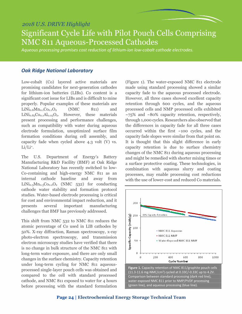
This shift from NMC 532 to NMC 811 reduces the atomic percentage of Co used in LIB cathodes by 50%. X-ray diffraction, Raman spectroscopy, x-ray photo-electron spectroscopy, and transmission electron microscopy studies have verified that there is no change in bulk structure of the NMC 811 with long-term water exposure, and there are only small changes in the surface chemistry. Capacity retention under long-term cycling for NMC 811 aqueous-processed single-layer pouch cells was obtained and compared to the cell with standard processed cathode, and NMC 811 exposed to water for 4 hours before processing with the standard formulation
(Figure 1). The water-exposed NMC 811 electrode made using standard processing showed a similar capacity fade to the aqueous processed electrode. However, all three cases showed excellent capacity retention through 600 cycles, and the aqueous processed cells and NMP processed cells exhibited ~75% and ~80% capacity retention, respectively, through 1,000 cycles. Researchers also observed that the differences in capacity fade for all three cases occurred within the first ~100 cycles, and the capacity fade slopes were similar from that point on. It is thought that this slight difference in early capacity retention is due to surface chemistry changes of the NMC 811 during aqueous processing and might be remedied with shorter mixing times or a surface protective coating. These technologies, in combination with aqueous slurry and coating processes, may enable processing cost reductions with the use of lower-cost and reduced Co materials.
Figure 1. Capacity retention of NMC 811/graphite pouch cells (11.3-11.6 mg-NMC/cm2) cycled at 0.33C/-0.33C up to 4.2V. Comparison between standard processing (dark red line), water-exposed NMC 811 prior to NMP/PVDF processing (green line), and aqueous processing (blue line).

Page 25 | Electrochemical Energy Storage Technical Team
2018 U.S. DRIVE Highlight
Development of an Extreme Fast-Charging Battery Researchers developed an internally heated fast-charging cell technology for low-temperature environments, demonstrating 10-minunte charging of high-energy lithium-ion batteries with significant cycle life.
The Pennsylvania State University
Fast-charging of lithium (Li)-ion batteries has been recognized as a key enabler of electric vehicles (EVs). There is development worldwide to build fast-charging stations with power up to 400 kW, able to charge a 200-mile-range EV (e.g., Chevrolet Bolt) in ~10 minutes.
A critical barrier to fast-charging is a phenomenon called Li plating, which can drastically reduce battery capacity and may result in safety hazards. Li plating occurs more seriously at higher charge rates, lower temperatures, and higher cell energy densities. Therefore, some state-of-the-art, high-energy battery cells (greater than 200 Wh/kg) may only withstand 30 minute charging at optimal temperatures and must utilize significantly reduced charge rates at low temperatures.
Researchers from Penn State University have developed an extreme fast-charging (XFC) technology that enables 10 minute charging of high-energy Li-ion cells at low temperatures without significantly impacting cell life. The XFC cells utilize a heated-charging strategy. A pre-heating step is performed before charging, which warms up the cell to ~60oC and thereby removes restrictions on cell charging. Although high temperatures degrades cell life, the relatively short time at high temperature is predicted to minimally impact cell life. By using a self-heating battery structure, the XFC cells have a rapid heating speed of less than 1oC/second, making the heating time short. Moreover, the elevated temperature at 60oC significantly boosts the kinetics of electrochemical reactions as well as mass transport in electrolyte and electrode materials, effectively alleviating Li plating.
Penn State University fabricated first-generation 33 Ah XFC pouch cells using a graphite anode and an NMC-based cathode, with an anode areal capacity of
3.0 mAh/cm2, giving a cell-level specific energy of 216 Wh/kg. Researchers performed cycling tests with 6C charging to 80% state of charge (SOC) followed by 1C discharge. Figure 1 shows the total charge time to reach 80% SOC and the 1C specific energy in the subsequent discharge of each cycle. The ambient temperature was 22°C. Pre-heat time was ~60 seconds. The rest time between two cycles was 11 minutes. Only about 10-min charging was at 60°C, and the rest of the cycle was at lower temperatures. Penn State estimates that the cell was exposed to 60°C for 167 hours over 1,000 cycles, i.e., 10-minute/cycle*1,000 cycles=10,000 min=167 hours. The Gen-1 cells sustained 700 XFC cycles before reaching 20% energy loss.
Researchers are now working to understand the impacts to pack energy density when the pack is being operated in a normal mode outside of the low-temperature fast-charge scenario, as well as the impacts to overall system efficiency with the inclusion of internal cell heating.
Figure 1. Dischargeable specific energy at 33 Ah size and total charge time of each XFC cycle. The cell is charged at 6C to 80% SOC in each cycle.

Page 26 | Electrochemical Energy Storage Technical Team
2018 U.S. DRIVE Highlight
Stable Lithium-Metal Electrodes Enabled by Atomic Layer Deposition Sealed Three-Dimensional Hosts Researchers demonstrate that applying a thin-layer coating through atomic layer disposition results in impressive cycling behavior at a Coulombic efficiency of 96%.
Stanford University, SLAC National Accelerator Laboratory
Lithium (Li)-metal has long been considered one of the most promising anode materials for advanced Li batteries (for example, Li-sulfur and Li-oxide), which could offer significantly improved energy density compared to state-of-the-art Li-ion batteries. Despite decades of intense research efforts, its commercialization remains limited by poor cyclability and safety concerns. The root causes are parasitic reaction between metallic Li and the organic liquid electrolyte, resulting in the formation of solid electrolyte interphase; and volume change upon Li plating/stripping, resulting in continuous formation and breaking of solid electrolyte interphase, which consumes both active Li and the electrolyte.
Until now, it has been challenging to completely shut down the parasitic reaction. Researchers found that a thin-layer coating applied through atomic layer deposition (ALD) on a hollow carbon sphere (HCS) host guides Li deposition inside the HCS and simultaneously prevents electrolyte infiltration by sealing pinholes on the shell of the hollow carbon sphere (Figure 1). By encapsulating Li inside the stable host, parasitic reactions were prevented, resulting in impressive cycling behavior. The team reported more than 100 cycles (in coin cells) at a high Coulombic efficiency (CE) of 96% in a carbonate-based electrolyte at a cycling rate of 2 mA/cm2 and a cycling capacity of 1 mAh/cm2 using ALD aluminum oxide (Al2O3)/HCS electrode, which
is superior to that of pristine copper electrodes and pristine HCS electrodes (Figure 2).
Figure 1. Soaking and electrochemical Li plating experiments. (A to C). Schematic and scanning electronic microscopy (SEM) of HCS electrodes soaked and dried in 1 M Li hexafluorophosphate (LiPF6)/EC/DEC electrolyte and saturated sodium chloride (NaCl)/water (H2O) solution. Blue arrows highlight the location of NaCl precipitation. (D to F) Schematic and SEM of ALD Al2O3/HCS electrodes soaked and dried in 1 M LiPF6/EC/DEC electrolyte or saturated NaCl/H2O solution. (H to J) Schematic and SEM of HCS electrodes after electrochemical Li plating in LiPF6/EC/DEC electrolyte. Red circles highlight the locations of plated Li inside and outside HCS. (K to M) Schematic and SEM of ALD Al2O3/HCS electrodes after electrochemical Li plating in LiPF6/EC/DEC electrolyte. Dashed red outline areas highlight the location of plated Li inside ALD Al2O3/HCS. All electrodes were cut open using focused ion beam for viewing. SEM images were taken with a sample rotation angle of 52°.
Figure 2. CE vs. cycle number plots of Cu, HCS, and ALD Al2O3/HCS in 30 μl of EC/DEC electrolyte with 1 M LiPF6, 1% VC, and 10% FEC.

Page 27 | Electrochemical Energy Storage Technical Team
2018 U.S. DRIVE Highlight
Higher-Rate Solid-State Lithium-Metal Batteries Solid-state non-flammable ceramic electrolytes enable use of high-capacity lithium-metal anodes with enhanced energy and abuse tolerance. Integrating a novel three-dimensional electrode architecture with low resistance interfacial layers has enabled high current density with ceramic electrolytes.
University of Maryland
Solid-state batteries are considered a possible next-generation energy storage device because they may enable the use of high-capacity lithium (Li)-metal anodes and provide abuse tolerance advantages due to inherently non-flammable solid-state electrolytes. Limiting issues have included high Li-electrolyte interfacial resistance and Li dendrite formation at high current density that leads to internal shorts. Researchers at the University of Maryland have made progress on these issues by modifying the Li-electrolyte interface and developing a unique three-dimensional (3D) extended electrode-electrolyte structure, achieving the U.S. Department of Energy’s (DOE) fast-charge target of 10 mA/cm2 for Li-metal cycling across a non-flammable, solid-ceramic electrolyte with low resistance and no degradation or shorting at room temperature.
The University of Maryland first overcame the intrinsic interfacial resistance between the Li7La3Zr2O12 (LLZ) ceramic electrolyte and Li-metal by developing nanometer thin coatings that enabled the Li-metal to wet the ceramic electrolyte surface. Researchers then developed a unique 3D architecture that extended the electrode/electrolyte interfacial area by 50X and provided support for a thin (~10 micron) dense separator layer, thus dramatically reducing resistance and enabling high current density cycling.
The tri-layer structures were produced through a scalable tape casting process. Without any gaps between grains, the dense layer was free of structural defects, thereby increasing mechanical strength while blocking dendritic Li growth that could short circuit the cell. The porous anode layer was then filled with Li-metal and the porous cathode layer filled with the desired cathode material. This was achieved with a Li-sulfur cell, as shown in Figure 1.
The maximum electrode size fabricated in the University of Maryland lab was 30 cm2.
This architecture has achieved the DOE fast-charge current density goal for Li cycling with a large per-cycle areal capacity, which has not previously been demonstrated for Li cycling in solid electrolytes. Future work will focus on increasing cumulative plating capacity and increasing the fraction of Li passed per cycle to further achieve higher energy targets. These results illustrate a potential means of producing Li-metal batteries with high specific energy density and improved abuse tolerance.
Figure 1. Tri-layer Li garnet cell with high interfacial surface area and short Li-ion conduction pathways resulting in high Li cycling current density and obtaining high energy density as a Li-sulfur cell.

Page 28 | Electrochemical Energy Storage Technical Team
2018 U.S. DRIVE Highlight
Development of Low-Cobalt Cathodes for Next-Generation, High-Energy-Density Lithium-Ion Batteries Ultra-low cobalt cathodes with higher energy density beyond current technology can address cost and cobalt supply chain volatility issues, which may become issues for transportation electrification.
University of Texas at Austin
Cobalt is a necessary transition metal in current lithium-ion batteries as it enables long-term cycle life. Unfortunately, raw cobalt materials have a volatile supply chain with costs tripling over the past 2 years. Some estimates suggest that the surging demand for electric vehicles could lead to cobalt shortages in less than half a decade.
The University of Texas at Austin (UT Austin) has developed high-nickel (Ni) LiNi1-xMxO2 cathodes (x ≤ 0.15), currently with 6% cobalt, with further cobalt content reductions expected in upcoming years. These materials achieve good energy and cyclability compared to commercial cathodes (Figure 1). Conventional high-Ni oxide cathodes suffer from issues such as structural defects, moisture sensitivity, high surface reactivity with electrolytes, and poor electrochemical reversibility during battery operation. In order to mitigate these issues, UT Austin has explored a wide variety of treatments on the high-Ni LiNi1-xMxO2 cathodes in conjunction with electrolyte modifications that can improve cycling stability, rate capability, and abuse tolerance. These materials are readily compatible with conventional cell components and fabrication technology, which is important for industrial adoption. The materials are synthesized at the kg-scale tank reactor at UT Austin.
The developments at UT Austin are supported by a host of characterization techniques, such as in-house X-ray diffraction and electron microscopy for compositional, morphological, and microstructural fine tuning. Additional material characterization is conducted through collaboration with synchrotron X-ray techniques at national laboratories, such as Brookhaven and Argonne National Laboratories. Advanced surface chemistry studies are performed with in-house X-ray photoelectron spectroscopy and
time-of-flight secondary-ion mass spectrometry (TOF-SIMS) experiments. TOF-SIMS provides sub-nanometer surface sensitivity and ultrahigh chemical selectivity, a technique for understanding unwanted electrode-electrolyte interactions. Figure 2 shows TOF-SIMS mapping of high-Ni LiNi1-xMxO2 electrodes after battery operation. Abuse tolerance of high-Ni LiNi1-xMxO2 cathodes is a known issue; thus further work will include cell level abuse testing.
Figure 1. Energy density of generation 1 (Gen #1) proprietary, LiNi1-xMxO2 ultralow-cobalt material compared with state-of-the-art commercial LiNi0.8Co0.1Mn0.1O2 (NCM811) cathode cycled in full pouch cells paired with graphite anodes.
Figure 2. TOF-SIMS images of cycled high-Ni LiNi1-xMxO2 cathode particles with Ni (58NiO-) indicated in green, as well as decomposed electrolytes (F-) in orange.

Page 29 | Electrochemical Energy Storage Technical Team
2018 U.S. DRIVE Highlight
High-Loading, Lean-Electrolyte Lithium-Sulfur Cells A novel cathode substrate enables high-energy sulfur cathodes to attain an improved cycle life of 200 cycles and capacity retention of 85% in a lean electrolyte condition necessary for higher energy cells.
University of Texas at Austin
Lithium (Li)-sulfur batteries are among the most promising and potentially low-cost high-energy density future battery systems due to their inherently high capacity, low cost, and the wide availability of sulfur. Developing Li-sulfur cells with a high-loading sulfur cathode in lean electrolyte conditions is one key to bringing the Li-sulfur battery technology to market. However, it has proven extremely challenging to develop a cell that simultaneously satisfies the above-mentioned metrics while also displaying acceptable cell performance in terms of high electrochemical efficiency and stability. As a result, the high performance of some Li-sulfur cells, as reported in the literature, are often obtained by using an insufficient sulfur loading of less than 4 mg/cm2 and sulfur content of less than 60 wt.% and an excess electrolyte/sulfur (E/S) ratio of greater than 11 μL/mg along with extra mass from aluminum-metal current collectors (~ 5 mg cm-2).
Researchers at the University of Texas at Austin have demonstrated a new concept by using a three-dimensional (3D), conductive cathode substrate with low surface area and nanoporosity that enables high sulfur loading (13 and 17 mg/cm) and sulfur content (75 and 80 wt.%) with an extremely low E/S ratio of 4.0μL/mg (Figures 1(a) and 1(b), respectively). The 3D conductive carbon substrate is commercially available and currently has a thickness of 70 microns. The electrode area used in these experiments is 1 cm2.
Such a cathode design simultaneously exhibits high effective capacity and long-term cycle stability. The high-loading cathodes demonstrate high areal capacities of 9-10 mAh/cm2 and high energy densities of 19-20 mWh/cm2, which are higher than relevant commercial rechargeable batteries, 2-4
mAh/cm2 and 8-13 mWh/cm2. On cycling at the lean electrolyte condition, the high-loading cathodes exhibit superior cycle stability for 200 cycles and attain capacity retention of as high as 85%, outperforming the benchmarks established for commercial Li-sulfur cells of 200 cycles and capacity retention of 80%. This work suggests that applying conductive cathode substrates with limited nanoporosity may be a viable pathway to enable further design and development of practical Li-sulfur batteries that could become competitive with commercial Li-ion technology in the long term.
Figure 1. Cyclability of the cells fabricated with the 3D conductive substrate cathodes with a sulfur loading, sulfur content, and E/S ratio of, respectively, (a) 13 mg cm-2, 75 wt.%, and 4.0 μL mg-1 and (b) 17 mg cm-2, 80 wt.%, and 3.9 μL mg-1.

Page 30 | Electrochemical Energy Storage Technical Team
2018 U.S. DRIVE Highlight
Cells Fabricated with Recycled Cathode Powder Demonstrate Excellent Cycling Behavior 1 Ah cells using recycled NMC111 have reached 3,800 cycles, showing less capacity fade than control cells made with commercial NMC111 material.
Worcester Polytechnic Institute and U.S. Advanced Battery Consortium
Given the steady rise in lithium-ion battery (LIB) use for electrified mobility applications, it is critical to ensure a viable strategy is in place to recycle end-of-life batteries efficiently and economically. Returning valuable materials back into the value chain minimizes the amount that must be extracted from primary sources such as mines.
LIB recycling faces some new challenges not seen with older technologies such as lead acid and nickel metal hydride. The successful drive to reduce costly metals such as cobalt and nickel (per unit energy) in automotive batteries has led directly to the lower intrinsic (metal) value present at end-of-life, which strains conventional business models. To address this, efforts have focused on developing cathode to cathode (C2C) recycling processes that would maximize the value of the recovered materials. However, most C2C processes grapple with the profusion of nickel/manganese/cobalt (NMC) cathode variants and their evolving nature (changing ratio of nickel/manganese/cobalt); LIB chemistry of choice for today’s electric vehicles (EVs) will not be the same in 10 years when the battery is recycled. Worcester Polytechnic Institute (WPI) has developed a hydrometallurgical recycling process with the flexibility to accommodate a complex and variable input stream. A mid-process adjustment enables “tuning” of the output to a desired stoichiometry (NMC ratio), as driven by changing market demand.
Over the course of the program, the project team (WPI, start-up Battery Resourcers and A123 Systems) recycled more than 1 full pack each of spent Chevrolet Volt cells, Focus EV cells and FCA 500-e cells, generating several hundred kilograms of cathode powder. The powder was used to make multiple lots of 1 Ah and 11 Ah cells, each from a different combination of incoming cell chemistries,
to demonstrate the process’ ability to make consistent NMC from a variable feedstock. Each build was accompanied by a control lot of equivalent cells made using commercial cathode powder for side-by-side evaluation. Figure 1 shows three lots of 1 Ah cells using recycled NMC111 made from different input feeds, as well as the control group (purple) made from commercial NMC111. The recycled lots have achieved 3,800 cycles to date under an aggressive cycling regime, and all three exhibit less capacity fade than the control group.
Figure 1. Results from 1 Ah cells made with recycled cathode NMC111 shown in red, green, and blue. Results from control cells made with commercial NMC111 shown in purple.
Finally, the team used process data to explore three different input feed scenarios using two separate cost models, one developed by Battery Resourcers and the new ReCell tool developed by Argonne National Laboratory. Both models considered a product of NMC111, as well as revenue-generating outlets for other recovered materials such as lithium carbonate, copper, and aluminum. In both cases (and with close agreement) economic modeling results indicate that at high volume (5 tpd), a cost neutral/positive recycling business case is achievable, whereby the extracted value of the cathode material compensates fully for recycling BOM, labor, CAPEX and other costs.

Fuel Cells

Page 32 | Fuel Cells Technical Team
2018 U.S. DRIVE Highlight
Highly Efficient and Durable Fuel Cell Catalyst Development of ultralow platinum loaded cathode catalyst that meets the U.S. DRIVE 2025 performance target.
Argonne National Laboratory
The performance, durability, and cost of fuel cell catalysts have a direct impact on the application of fuel cell vehicles (FCVs). To enable a full range of efficient, clean, and advanced light-duty FCVs, innovative cathode catalysts with high performance, particularly at high current density/power density regions are required. A team led by Argonne National Laboratory (ANL) recently developed a series of hybrid catalysts with ultralow platinum (Pt) dispersed on platinum group metals-free (PGM-free) nanofiber supports. The active catalytic support was derived from a metal-organic-framework through heat activation and contained uniformly dispersed, high-density active sites. The new catalysts have demonstrated improved activity and durability at a significantly reduced Pt-loading. Table 1 shows that the new catalyst has met a majority of the U.S. DRIVE 2025 fuel cell catalyst/membrane electrode assembly (MEA) performance metrics, including the target at high current/power density regions (performance @675 mV). A paper describing this work was published in a recent issue of Science (DOI: 10.1126/science.aau0630, 2018).
ANL’s hybrid catalysts improved oxygen reduction reaction (ORR) performance through catalysis between the Pt-transition metal core-shell nanoparticles (NPs) and transition metal-based active catalytic substrate. Figure 1 shows the scheme of the catalysis process. Briefly, both Pt-transition metal NPs and PGM-free sites simultaneously convert the incoming oxygen in the fuel cell cathode. Because PGM-free sites are densely populated, they can interact with high flux of oxygen more efficiently than the low number of Pt NPs. Pt NPs, on the other hand, catalyze ORR at a much faster rate and complete conversion of the intermediate products such as peroxide generated by PGM-free sites. The
synergy between the two catalytic components enabled ANL’s catalyst to reach ORR performance similar to the state-of-art commercial catalyst.
Remaining challenges include further reducing Pt loading while maintaining synergistic interaction at different fuel cell voltages, better humidity management, and improved fuel cell operation with air. Scale-up manufacture in a cost-effective manner will be a challenge as well.
Table 1. Catalyst performance and durability met US DRIVE’s target matrix.
Figure 1. Schematic showing of synergistic ORR catalysis between PGM-free active site and Pt-transition metal nanoparticles.

Page 33 | Fuel Cells Technical Team
2018 U.S. DRIVE Highlight
High Power Durable Membrane Electrode Assembly Exceeds Performance Targets State-of-the-art membrane electrode assembly exceeds the U.S. DRIVE 2020 performance targets and combines chemical-mechanical accelerated protocols for durability testing.
General Motors
The performance and durability of the membrane electrode assembly (MEA) directly impacts the cost of fuel cells and their adaptation as a mainstream alternative to internal combustion engines. Using highly active catalysts at low platinum loading, and thinner membranes aimed at lowering cost, tends to negatively impact both performance and long-term durability of the MEA, and hence cost. General Motors (GM), in partnership with Giner, University of Texas at Austin, and the U.S. Department of Energy’s FC-PAD Consortium, has performed a systematic evaluation of best-in-class materials and integrated them to generate a state-of-the-art MEA. The final MEA exhibits 1,275 mW/cm2 power density, and platinum group metal (PGM) content of 10 kW/g PGM, both exceeding current U.S. DRIVE 2020 targets.
Oxygen and proton transport resistance negatively impact high power performance. Studies of several best-in-class catalysts indicate the carbon support pore size distribution and corresponding surface area as the most significant factors influencing transport properties. As shown in Figure 1, the oxygen transport resistance is dependent on the “micropore” (less than 2 nm) surface area, lower micropore area exhibit lower oxygen transport resistance. Similarly, the proton transport resistance is dependent on the macropore (defined as larger than 8 nm) surface area. An ideal carbon support for high power would have lower micropore and macropore surface area in favor of mesopore surface area (3-7 nm).
Another key accomplishment of the project is the development of a combined chemical and mechanical highly accelerated stress test. Using a current distribution tool enabled quantitative measurement of mechanical stress (high frequency resistance) and corresponding membrane state of
health (cross over measurement). The study indicates severe membrane thinning (chemical in nature) at the outlet where mechanical stress is high, suggesting a possible interaction between mechanical stress and chemical degradation (Figure 2). (GM also observed a depleted concentration of the chemical degradation mitigant, cerium [Ce], at the outlet). Future work will focus on the role of Ce movement in regions of high mechanical stress as well as the impact of local shorts on membrane thinning. A voltage cycling design of experiments will identify benign operating condition for extended durability.
Figure 1. Effect of carbon support on transport properties.
Figure 2. Distributed segment mapping at 1213 h. (a) hydration amplitude (Δλ), (b) diffusive crossover current change (mA/cm2), (c) Ce concentration X-ray fluorescence image, and (d) Ce intensity scale.

Page 34 | Fuel Cells Technical Team
2018 U.S. DRIVE Highlight
New Intermetallic Catalysts Meet Durability Targets New catalysts based on ordered platinum-cobalt alloy nanoparticles have improved cobalt retention during fuel cell testing, enabling high durability.
Los Alamos National Laboratory
New intermetallic platinum-cobalt catalysts developed at Los Alamos National Laboratory (LANL) use atomic-level ordering to stabilize cobalt atoms within the catalyst nanoparticles, reducing the leaching rate of cobalt and enabling high cobalt content to be maintained even after durability testing. The key innovation in 2018 was developing a new synthetic method that enables simultaneous achievement of small nanoparticle size (4 nanometers or less) and high degree of ordering. Previous efforts on intermetallic platinum-cobalt nanoparticles were limited by excessive particle growth suffered during the ordering process. By avoiding this particle growth, the LANL catalyst maintains high surface area and high catalytic activity while also exhibiting improved durability.
Conventional fuel cell catalysts use alloying with a base metal, which is usually cobalt, to increase the catalytic activity of the platinum-based catalyst. Cobalt leaching during fuel cell operation typically reduces the cobalt content to around 10% to 12% of the total metal content. The loss of cobalt causes degradation of the catalyst performance, while the leached cobalt accumulates in the fuel cell membrane and ionomer, degrading the performance of those components. Therefore, finding ways to maximize cobalt content and prevent cobalt leaching are critical to improving fuel cell durability.
The intermetallic platinum-cobalt nanoparticles developed at LANL retain the ordered structure even after durability testing (Figure 1). They also have greatly improved cobalt retention compared to random alloys, enabling 40% higher cobalt content after durability testing (Table 1). This higher cobalt content enables higher catalytic activity throughout the catalyst's lifetime. As a result, these catalysts meet U.S. DRIVE’s mass activity target as well as the
durability targets of 40% loss in mass activity and 30 mV loss in performance at 0.8 A/cm2 after 30,000 square-wave voltage cycles. These catalysts also enable high fuel cell performance, achieving a power density of 1.1 W/cm2 at 250 kPaabs in hydrogen/air testing.
Figure 1. Scanning transmission electron micrograph of an intermetallic platinum-cobalt nanoparticle after 30,000 voltage cycles in a fuel cell. The distinctive striped pattern reveals that the ordered platinum-cobalt core remains intact even after durability testing.
Table 1. Cobalt atomic percentage in random alloy versus ordered alloy platinum-cobalt nanoparticles before and after durability testing. Ordered intermetallic platinum-cobalt exhibits 40% higher cobalt content after durability testing, despite beginning the test with lower cobalt content.
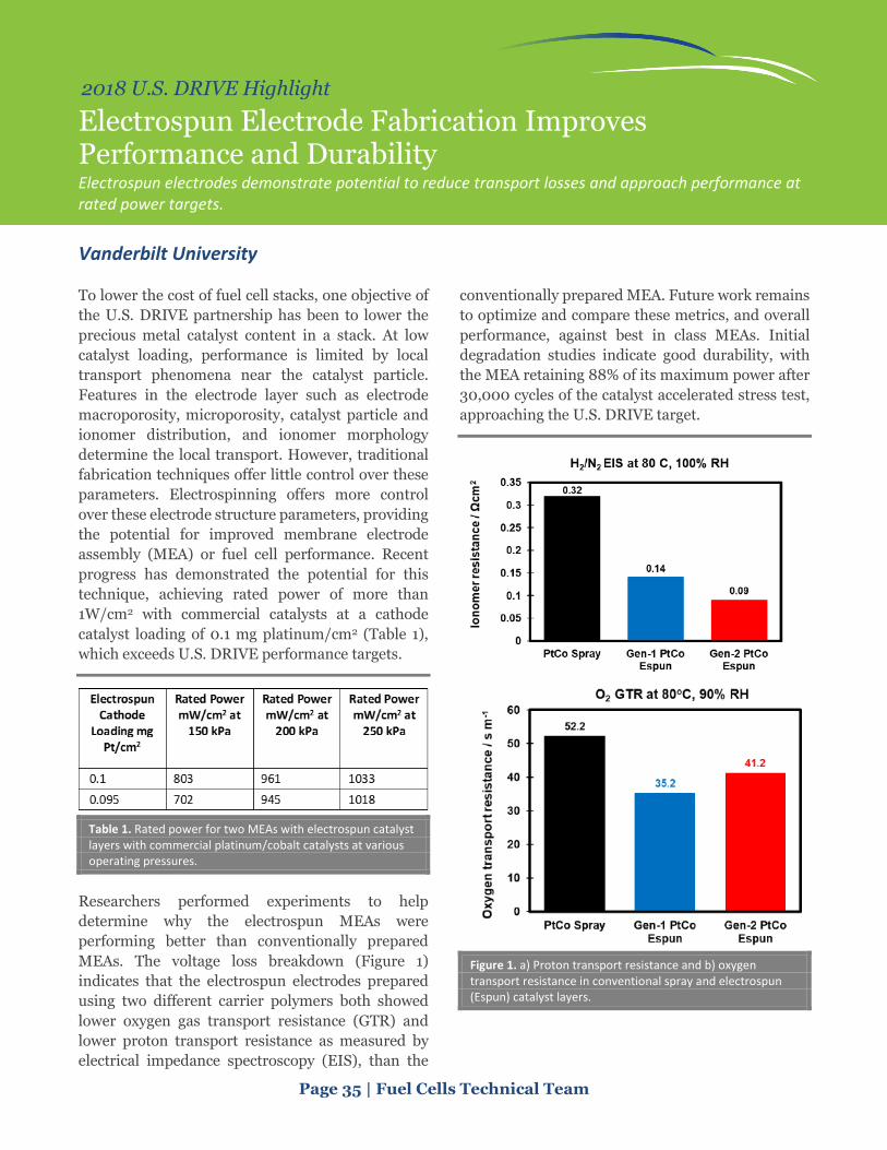
Page 35 | Fuel Cells Technical Team
2018 U.S. DRIVE Highlight
Electrospun Electrode Fabrication Improves Performance and Durability Electrospun electrodes demonstrate potential to reduce transport losses and approach performance at rated power targets.
Vanderbilt University
To lower the cost of fuel cell stacks, one objective of the U.S. DRIVE partnership has been to lower the precious metal catalyst content in a stack. At low catalyst loading, performance is limited by local transport phenomena near the catalyst particle. Features in the electrode layer such as electrode macroporosity, microporosity, catalyst particle and ionomer distribution, and ionomer morphology determine the local transport. However, traditional fabrication techniques offer little control over these parameters. Electrospinning offers more control over these electrode structure parameters, providing the potential for improved membrane electrode assembly (MEA) or fuel cell performance. Recent progress has demonstrated the potential for this technique, achieving rated power of more than 1W/cm2 with commercial catalysts at a cathode catalyst loading of 0.1 mg platinum/cm2 (Table 1), which exceeds U.S. DRIVE performance targets.
Table 1. Rated power for two MEAs with electrospun catalyst layers with commercial platinum/cobalt catalysts at various operating pressures.
Researchers performed experiments to help determine why the electrospun MEAs were performing better than conventionally prepared MEAs. The voltage loss breakdown (Figure 1) indicates that the electrospun electrodes prepared using two different carrier polymers both showed lower oxygen gas transport resistance (GTR) and lower proton transport resistance as measured by electrical impedance spectroscopy (EIS), than the
conventionally prepared MEA. Future work remains to optimize and compare these metrics, and overall performance, against best in class MEAs. Initial degradation studies indicate good durability, with the MEA retaining 88% of its maximum power after 30,000 cycles of the catalyst accelerated stress test, approaching the U.S. DRIVE target.
Figure 1. a) Proton transport resistance and b) oxygen transport resistance in conventional spray and electrospun (Espun) catalyst layers.

Page 36 | Fuel Cells Technical Team
2018 U.S. DRIVE Highlight
Characterizing State-of-the-Art Fuel Cell Materials Characterizing state-of-the-art fuel cell materials in terms of composition, structure, performance, and durability yields knowledge to advance fuel cell system development.
Fuel Cell Performance and Durability Consortium
The U.S. Department of Energy’s Fuel Cell Performance and Durability Consortium (FC-PAD) applied its analytical capability to state-of-the-art fuel cell stack components from the Toyota Mirai, evaluating the membrane electrode assembly (MEA) and bipolar plates. The results yield knowledge that the fuel cell community can use t0 advance fuel cell system development. FC-PAD’s analysis included the following:
• Measured the thickness of the anode, cathode catalyst layers, gas diffusion layers (GDLs), and membrane with scanning electron microscope cross-sections.
• Determined the MEA composition, quantitated the catalyst loading, and mapped elemental distribution with X-ray fluorescence.
• Determined the relative platinum (Pt) particle distribution with small angle X-ray scattering and X-ray diffraction.
• Used the relative platinum (Pt) and cobalt (Co) lattice parameters with extended X-ray absorption fine structure.
• Measured the catalyst surface area. • Determined the 3-dimensional MEA structure
and location of particles, such as ceria radical scavenging particles utilizing X-ray computed tomography.
• Determined the electrochemically active surface area.
• Mapped the catalyst layer and carbon/PtCo/ionomer distributions and measured PtCo particle size with energy dispersive spectroscopy-scanning tunneling electron microscopy.
• Evaluated the ionomeric polymer compositional side groups with Fourier transmission infrared and nuclear magnetic resonance.
• Examined the inomer/catalyst composition using thermal gravimetric analysis.
• Defined the GDL porosity with mercury intrusion porosimetry.
• Measured the bipolar plate composition and evaluated the surface coating depth utilizing X-ray photoelectron spectroscopy.
• Measured relative water content within the operating fuel cell using neutron imaging.
Figure 1 shows the catalyst layer thickness on the 300-hour operated MEA and after accelerated stress tests (ASTs). The MEA showed significant performance degradation and thinner catalyst layer after both catalyst and catalyst support ASTs. However, no significant changes to the structure or chemistry were observed in the real-world MEA that had been run for 3,000 hours in the Mirai, meaning that sophisticated system mitigation strategies in the vehicle system enabled use of conventional materials to achieve fuel cell durability.
There are factors that still need to be resolved to enable widespread commercialization. For example, U.S. DRIVE has established a 2025 cost target of $40/kW to reduce the amount of Pt in the MEA to 0.10 mg Pt/cm2. The total amount of Pt loading in the cathode and anode was around 0.37 mg/cm2.
Figure 1. Cathode catalyst layer thickness after 300 hours, catalyst AST, and catalyst support AST.

Hydrogen Storage

Page 38 | Hydrogen Storage Technical Team
2018 U.S. DRIVE Highlight
Improving the Kinetics and Thermodynamics of High-Capacity Complex Metal Hydrides Collaborative work by several projects enabled by the HyMARC effort has resulted in significant improvements in the hydrogen storage properties of magnesium borohydride.
Hydrogen Materials—Advanced Research Consortium
Multiple projects collaborating within the U.S. Department of Energy’s Hydrogen Materials—Advanced Research Consortium (HyMARC) Energy Materials Network consortium have successfully reduced the temperature and pressure required for magnesium borohydride (Mg(BH4)2) to reversibly store hydrogen (H2). Mg(BH4)2 is a promising H2
storage material for fuel cell electric vehicles potentially offering increased H2 capacity (14.8 wt.% theoretical) and significantly lower pressure operation. This results in lower cost while maintaining vehicle range and performance. High temperatures and pressures are required to overcome the constraints with thermodynamics and kinetics of this material’s complex H2 uptake and release reactions pathways. This prevented using the material in a practical storage system.
New results from HyMARC show that there are routes to reduce these barriers, enabled by the consortium’s collaborative experimental and theoretical approach across national laboratories, universities, and industry. Previously, reversibly charging H2 into magnesium diboride (MgB2) to form Mg(BH4)2 required 400°C/900 bar recharging pressure. A HyMARC project at the University of Hawaii set out to improve these conditions by forming etherate adducts of MgB2 in an effort to alter the chemical pathways by which H2 is stored and subsequently released. When MgB2 is ball milled with tetrahydrofuran (THF), an etherate material forms, which enables hydrogenation to Mg(BH4)2 at milder conditions of 300°C /700 bar.
Theory and computational work by the HyMARC core team at Lawrence Livermore National Laboratory helped to explain why this improvement was observed. Their molecular dynamics simulations indicated that binding THF molecules to
the MgB2 structure disrupts the material’s very stable sheet-like structure. This causes the formation of structural defects and an overall energetic destabilization of the structure, subsequently facilitating H2 storage under milder conditions.
A second HyMARC project with Liox Power and HRL Laboratories demonstrated improvements in the rate at which MgB2 absorbs H2. Their technique utilizes a molten salt eutectic that acts as a solvent to mitigate the typically balky diffusion reactions that occur in solid state hydride systems. Cycling of MgB2 mixed with an iodide-based eutectic was achieved. The H2 uptake was approximately 20 times greater than those measured for neat MgB2 with identical temperature ramp rates up to 350 °C. (Figure 1).
The results described are only initial proof-of-concept results obtained within Phase 1. Phase 2 efforts will focus on optimizing the recharging conditions necessary for Mg(BH4)2 to meet U.S. DRIVE’s 2025 H2 storage system cost target of $9/kWh.
Figure 1. H2 release data for MgB2 after hydrogenation using an iodide electrolyte salt (red) implying improved H2 uptake compared to MgB2 hydrogenated with no electrolyte (blue).

Page 39 | Hydrogen Storage Technical Team
2018 U.S. DRIVE Highlight
Low-Cost High-Strength Carbon Fiber for Composite Overwrapped Pressure Vessel Applications Identified a path towards achieving an 18% reduction in the cost of high-strength carbon fiber.
University of Kentucky Center for Applied Energy Research
The University of Kentucky Center for Applied Energy Research (UK CAER) has shown a path to achieve an 18% reduction in the cost of carbon fiber (CF) (Figure 1), with potential for an overall cost reduction of greater than 60% when compared to traditional T700S-type CF. U.S. Department of Energy analyses concluded that over 70% of the cost of Type IV, 700-bar hydrogen storage composite overwrapped pressure vessels (COPVs) is from the CF alone. As a result, CF cost reduction is key to achieving the U.S. DRIVE 2025 hydrogen storage system goal of $9/kWh.
The 60% overall CF cost reduction can be accomplished through developing a novel, lower-cost polyacrylonitrile (PAN) precursor (14% cost reduction identified); efficient solvent recovery from wastewater (4% cost reduction identified); hollow precursor fibers (~15% cost reduction projected); and faster oxidation and carbonization times (~30% cost reduction projected).
During phase 1 of the project, UK CAER validated a new, low-cost PAN precursor polymer called TechPAN ($3/kg polymer), which is 14% lower cost than traditional T700S-type CF with a cost of ~$29/kg. In addition to lower cost, the brand-agnostic, TechPAN precursor material resulted in an average CF strength of 550 ksi, with nearly 20% of the filaments showing more than 700 ksi and a modulus of 46.3 Msi. This is nearing the performance of the incumbent T700S CF, which has a tensile strength of 711 ksi and modulus of 33.4 Msi.
UK CAER also demonstrated an efficient solvent recovery process from wastewater, resulting in an additional 4% cost reduction compared to the baseline T700S-type CF. This process uses activated carbon to remove the solvent from the waste water,
which resulted in nearly a 40% reduction in fresh water usage required to produce precursors.
Finally, in the second phase of the project, UK CAER is pursuing hollow precursor fiber tow spinning. If successful, hollow fibers will offer potential for lower mass of CF required as well as faster oxidation and carbonization processing times due to oxidation occurring from both inside and outside of the fiber. In total, the use of hollow precursor fibers could offer an additional ~45% cost reduction.
Traditional high-strength CF production is capital intensive, driven by the production of high-quality PAN precursors. This creates a significant barrier to entry into the market space for new CF producers. These results show that T700S CF strength can be obtained with lower cost, off-the-shelf precursors without the need to develop new PAN formulations. As a result, this project offers a pathway to significantly lower the risk for new CF producers to enter into the COPV market space.
Figure 1. UK CAER’s identified (18%) and projected (~45%) cost reductions (total of greater than 60%) when compared against the baseline T700S CF.

Materials

Page 41 | Materials Technical Team
2018 U.S. DRIVE Highlight
Integrated Computational Materials Engineering Development of Carbon Fiber Composites for Lightweight Vehicles Project developed engineering tools needed for designing a light-duty vehicle carbon fiber subframe.
Ford Motor Company
Auto manufacturers use lightweight materials to meet the increasing demands of fuel efficiency. Carbon fiber reinforced polymer (CFRP) composites with a density of 1.55 g/cm3 and a tensile strength of 2,000 MPa in the fiber direction are among the most promising candidates to replace the metals currently used for structural components. This project develops integrated computational materials engineering (ICME) tools to design a light-duty vehicle carbon fiber subframe (Figure 1). The subframe must meet requirements and achieve at least a 25% weight reduction with a cost increase of less than $4.27 per pound of weight saved when compared to the baseline stamped steel subframe.
Researchers from Ford lead the project team with colleagues from Dow Chemical Company, Northwestern University, the University of Maryland, and partners from software companies, Livermore Software Technology Corporation (LS-DYNA), Esteco (modeFRONTIER), HBM Prencia (nCode), and Autodesk, Inc. (Moldflow). The 4-year project concludes in early fiscal year 2019, and focuses on three epoxy CFRP composites: chopped carbon fiber, unidirectional carbon fiber, and woven carbon fiber.
The mechanical properties of CFRP are highly direction-dependent. The initial fabric, the material layout, and the preforming and molding processes determine the final local orientation of the fiber. An optimized component design needs tools that are capable of predicting the performance of the CFRP subframe based on fiber architecture, molding process, and curing history with consideration of the uncertainties and probabilistic nature of materials and molding processes. The ICME tools developed in this project meet this design challenge. Including the effects of the manufacturing process on the CFRP material in the subframe improves the robustness of
the design, thus avoiding costly redesign and prototype iterations.
Results reinforce the need to predict the local fiber orientation in order to predict CFRP performance. Over a quarter of the project’s efforts address material testing to populate detailed material models for molding, crash, and structural performance. A large volume of material data with test parameters is now included in a National Institute of Standards and Technology (NIST) database for composites. The software partners improved their models and analyses for carbon fiber composite. The subframe design demonstrates the success of the ICME tools. The project suggests a steel intensive design with 16% sheet molding compound and 5% unidirectional carbon fiber meets both the cost and weight targets.
Figure 1. ICME-based process of top-down material design and bottom-up component design with uncertainty and validation.

Page 42 | Materials Technical Team
2018 U.S. DRIVE Highlight
Development and Integration of Predictive Models for Manufacturing and Structural Performance of Carbon Fiber Composites in Automotive Applications
ICME technologies can potentially eliminate significant bottlenecks to meeting lightweighting potential.
General Motors
The goal of this project is to develop an integrated suite of state-of-the-art computational modeling tools based on integrated computational materials engineering (ICME) methodology that are critically needed to enable structural carbon fiber (CF) applications in automobiles (Figure 1). These tools are designed to predict the manufacturing and structural performance of CF composites. During the first phase of the project, General Motors (GM) calibrated and validated both the manufacturing and structural performance tools, including a stochastic driver, against coupon and component level tests. The difference between predictions and experimental results was limited to less than 15%. During the second phase of the project, the manufacturing and performance tools will be integrated by mapping the manufacturing outcomes (e.g., fiber angles, residual stresses, degree of cure, and defects such as voids, dry patches, and wrinkles) into the structural models. Also, using the tools developed in this project, the team is redesigning an automotive assembly currently manufactured in steel using CF composites, with the objective of comparing the assembly performance with modeling predictions. The team will determine mass savings and cost increase per pound saved compared to the steel assembly.
In fiscal year 2018, GM made major efforts in designing a CF automotive assembly for a high-volume, light-duty automobile using the integrated manufacturing and structural performance tools developed in this project. The team investigated various CF materials friendly to high-volume automotive manufacturing (e.g., non-crimp and chopped systems) and manufacturing processes (e.g., resin transfer molding [RTM] and compression molding), enabling a 3-5 minute cycle time. Researchers designed four large components to be
manufactured using high-pressure resin transfer molding (HP-RTM). Final designs of the components of the assembly, including the HP-RTM process design, were provided for building the tools.
In fiscal year 2019, researchers will build and certify a CF automotive assembly. The team will validate stochastic manufacturing tools developed in the project by comparing the experimental data measured using sensors embedded in the tools. The computational structural performance tools developed in this project will be validated by comparing the experimental results and predictions for a challenging crashworthiness load case (side pole impact performance) of the assembly. Furthermore, the team will compare the weight, cost, and performance with the existing steel design.
The availability of these integrated computational tools to predict manufacturing and structural performance of structural composites can potentially eliminate significant bottlenecks to achieving substantial lightweighting potential with large-scale implementation of CF composites.
Figure 1. Process flow of ICME tool development.

Page 43 | Materials Technical Team
2018 U.S. DRIVE Highlight
Advanced Characterization of Magnesium Coatings Better understanding of how the substrate magnesium alloy influences protective coating formation provides a basis to design alloy-coating systems for improved corrosion resistance.
Oak Ridge National Laboratory
Inadequate corrosion resistance is a key limiting factor to the widespread adoption of magnesium (Mg) alloys for vehicle lightweighting and improved fuel economy. Oak Ridge National Laboratory researchers are employing advanced electron microscopy, neutron scattering, and mass spectrometric characterization tools to gain fundamental knowledge needed to successfully design more corrosion-resistant Mg alloys and coatings. Project collaborators include a Mg alloy producer, a coating producer, a Tier 1 automotive supplier, and three universities.
In 2018, the project team studied the impact of the Mg alloy substrate on the resultant morphology, chemistry, and protectiveness of the coatings formed by state-of-the-art electro-ceramic and electro-coat top coat processing. The Mg alloys were selected to represent a range of key alloy classes: Mg-aluminum (Al)-type wrought AZ31B; cast AZ91D; zirconium (Zr)/rare earth (RE)-type-wrought ZE10A; and wrought WE43. The same coating processing parameters were used for all Mg alloys studied.
Cross-section scanning electron microscope (SEM) and scanning transmission electron microscope (STEM) analysis of electro-ceramic coated Mg alloys found that the substrate alloy had an unexpectedly strong impact on electro-ceramic coating thickness and morphology. The Mg substrate alloys with higher levels of Al or RE additions resulted in much rougher and thicker electro-ceramic coatings and, in the case of high RE additions in WE43, an unexpected striated local-layered structure at the alloy coating interface. Electro-ceramic coating thicknesses ranged from a few microns for AZ31B to several tens of microns on WE43 (Figure 1). Researchers observed segregation of Al from the alloy to the electro-ceramic for AZ31B nd AZ91D,
whereas Zr and RE additions were not observed to migrate to the electro-ceramic coatings formed on ZE10A and WE43.
The team found the electro-coat top coats thoroughly percolated into the inner regions of the porous electro-ceramic structures, which were also fully preserved after deposition of the electro-coat (Figure 1). The corrosion resistance of the as-electro-ceramic coated alloys followed trends observed for the uncoated alloys. The addition of the electro-coat top coat resulted in excellent corrosion resistance that was comparable for all four alloys. However, corrosion exposures for scribed (i.e., intentionally damaged) coatings resulted in a significant degradation of resistance for the WE43 alloy. Preliminary findings suggest the susceptibility to attack may be related to the inner striated coating morphology formed on WE43 but not the other alloys. These findings will help provide the basis to guide optimization of Mg alloy coating systems.
Figure 1. Cross-section images by SEM (a, b) and STEM (c, d) showing the as-coated structure formed on wrought AZ31B and WE43 alloys with electro-ceramic coating and electro-coat top coat.

Page 44 | Materials Technical Team
2018 U.S. DRIVE Highlight
Close Proximity Electromagnetic Carbonization Development of a lower-cost, less energy-intensive method for converting precursors into carbon fiber.
Oak Ridge National Laboratory
Carbon fiber (CF) is used in composite parts mostly for structural applications because of its low density, high strength, and modulus. However, use of this material was limited to the aerospace and defense industries until the late 1990s, when its cost began to decrease. The U.S. Department of Energy and Oak Ridge National Laboratory (ORNL) are currently pursuing a strategy to further reduce the cost of manufacturing CF during the carbonization stage. Lower-cost precursors and composite production methods are under development, and a less expensive cost oxidative stabilization process is being commercialized.
The carbonization stage of the conversion process (highlighted in green in Figure 1) consumes a significant amount of energy. The current state of the art still uses traditional high-temperature furnaces that not only heat the fiber but the interior walls and gases as well. A much more energy-efficient approach would be to directly couple the heat to the fiber and nothing else.
In 2013, experimental work undertaken by RMX Technologies and ORNL led to an initial furnace prototype that demonstrated possible carbonization of oxidized polyacrylonitrile (PAN) fiber in the near field of antennas using radio frequency power. However, the carbonized area was not uniform. In 2016, the Close Proximity Electromagnetic Carbonization (CPEC) project was initiated to demonstrate over a 3-year period that this furnace concept was commercially viable and that the cost of the carbonization stage could be reduced such that large-scale adoption of the concept by industry would be achieved (for production of 1,500 annual metric tons or more, 24 hours per day/365 days a year).
The objectives of this project are to reduce unit energy consumption (kWh/kg) by 50%, reduce carbonization costs by 25%, produce the same or better quality CF compared to currently available industrial grades, and scale the technology to an annual nameplate capacity of 1 metric ton and demonstrate this capability by the project end date.
In 2018, demonstration work with a lab-scale furnace, the CPEC-3, was completed, and this led to the design and start of fabrication for the CPEC-4 furnace with an annual capacity of 1 metric ton.
The CPEC-4 will demonstrate scalability and performance capabilities of the technology going from the lab scale to the pilot line scale. The project will be completed in fiscal year 2019 with the goal of subsequently combining this technology, which completes the low-temperature carbonization step, with ORNL’s Microwave Assisted Plasma technology focused on the high-temperature carbonization step. This expected follow-on project will result in a combined carbonization process that fully utilizes electromagnetic heating at atmospheric pressure to produce high-quality CF.
Figure 1. Flow diagram of the conventional PAN–based CF conversion process. The highlighted carbonization stage is the focus of this project. The low-temperature stage is the main focus (solid line), but the high-temperature stage is partially covered as well (dashed line).

Page 45 | Materials Technical Team
2018 U.S. DRIVE Highlight
Thin, Advanced High-Strength Steel with Carbon Fiber Reinforced Polymer Coating Development of a carbon fiber/epoxy stiffening coating for downgauging advanced high-strength steel.
Oak Ridge National Laboratory
This project’s goal is to develop a carbon fiber-epoxy coating for downgauging advanced high-strength steel body panels, to reduce vehicle weight and lower the cost of weight reduction. The process involves using thinner gauge steels than are currently used, stiffened by the application of the carbon fiber reinforced epoxy (CFRE) on one side. The development team includes two industrial manufacturers; the U.S. Department of Energy’s Lightweight Materials Consortium (LightMAT); and two DOE national laboratories, Oak Ridge National Laboratory (ORNL) and Idaho National Laboratory (INL). The team is developing an understanding of how to apply the coating, along with how it will perform in service. Evaluating the long-term durability of materials manufactured using this technology is one of the goals as well.
The team developed a proprietary, low specific gravity CFRE, and preliminary testing demonstrated the concept. Researchers applied a thin layer of a CFRE to a stamped sheet of steel with residual stamping oils from the mill in a time corresponding to automotive processing (~15 seconds) and processed following automotive e-coat procedures (phosphating + 175-200oC heating for 20 minutes) to complete the curing. No problems with adherence or performance were noted. While the CFRE adds weight to a thin gauge steel panel, it is much less weight than is displaced from using thicker conventional mild steel gauges. Total door coverage adds 450 grams while selective coverage adds 115 grams. Coupled with downgauging from 0.6 mm to 0.5 mm thick panels, the system mass savings is greater than 15%. The application of the coating showed significantly increased dent resistance, oil canning resistance, and part stiffness.
This program used recycled carbon fiber. The final coating selected was with the 100 µm fiber at the lowest concentration (15 wt.%) evaluated. ORNL conducted three-point bend tests to determine the coating thickness on coated and uncoated steel samples varying both the coating thickness and the thickness of the steel substrate. A steel thickness of 0.80 mm could be replaced by a steel door thickness of 0.60 mm with a 0.5 mm CFRE coating (Table 1).
Table 1. Flexural bending load of DP500 steel to achieve a 0.1 mm deflection with the CFRE coating applied.
Next, the team conducted dent testing (Figure 1) and oil canning testing of the coated and uncoated steel samples. Researchers used a 25.4 mm diameter hemispherical indenter to apply a vertical load, then recorded the amount of force necessary to create an indentation of 0.1 mm. A 0.5 mm door panel with the patch applied had the same or better dent resistance than a 0.6 mm door panel without the patch applied.
Figure 1. Test sample showing the three test locations and the dent testing indenter.

Page 46 | Materials Technical Team
2018 U.S. DRIVE Highlight
Joining Core Program Established as Multi-Lab Partnership National laboratories are conducting early stage research on difficult to join combinations of lightweight materials.
Oak Ridge National Laboratory, Pacific Northwest National Laboratory, and Argonne National Laboratory
The U.S. DRIVE Materials Technical Team has identified joining as one of the major research priorities to enable use of lightweight materials. Current joining practices employed in high-volume automotive manufacturing were developed primarily for steels with some more recently adapted and deployed technologies designed for aluminum-aluminum and aluminum-steel joints. Aluminum joining technologies have limited use for carbon fiber reinforced polymer (CFRP) and magnesium (Mg), which are viewed as the two materials of highest potential for vehicle lightweighting.
The Joining Core Program is a collaborative research program initiated jointly between Oak Ridge National Laboratory and Pacific Northwest National Laboratory with support from Argonne National Laboratory, leveraging existing expertise and past efforts in joining technology development and lightweight materials R&D capabilities. Collaborative, early-stage research conducted through this program will address multi-material joining and associated compatibility challenges that currently limit the integration of lightweight materials for vehicle structures. The initial three material combinations researched through the program are CFRP-steel, Mg-steel (Figure 1), and CFRP-Mg. The program seeks to develop scientific understanding across five areas: microstructure and morphology, mechanical characterization, simulation of joining processes and performance, corrosion science, and manufacturability. The program will emphasize an increased understanding of the joining interface from the atomic length scale to the lab sample length scale for all joining methods and material combinations.
Figure 1. Cross-section of an ultrasonic weld between Mg and galvanized steel at the center of the weld (left) and the edge of the weld (right). Optical images on the top with elemental mapping on the bottom.
The objective of the Joining Core Program is to deliver industrially relevant joining technologies that enable increased use of lightweight materials in vehicles. These technologies will be proven at the lab scale with a robust understanding of the underlying science. Once lab-proven (technology readiness level 4), industry can either license the technology directly for internal development or partner with the national laboratories to further mature the technology in the public domain. The fundamental scientific investigations that take place during the course of developing the joining technologies will be disseminated as early-stage research publications.

Page 47 | Materials Technical Team
2018 U.S. DRIVE Highlight
Low-Cost Magnesium Extrusion via Shear Assisted Processing and Extrusion (ShAPE™) Extruding advanced magnesium alloys with higher strength, ductility, and energy absorption rival more costly rare-earth containing alloys, but without complicated production methods.
Pacific Northwest National Laboratory
Magnesium (Mg), being the lightest of structural metals, has a huge potential for lightweighting the chassis or body of future vehicles. However, automotive manufactures have been slow to adopt Mg due to factors such as the need for costly rare-earth (RE) additives and slow manufacturing cycle-times. The Pacific Northwest National Laboratory (PNNL) and a Tier 1 supplier are collaborating to develop a new technology that achieves greater properties with Mg alloys, but without RE additives or complex processing methods. Shear assisted processing and extrusion (ShAPE™) (Figure 1) is being developed as a new approach to fabricating extruded profiles with improved material performance and significant process advantages, such as improved efficiency.
Figure 1. Cross section of tooling showing direct tubular extrusion using the ShAPE™ process.
With ShAPE™, the extrusion die and Mg billet counter rotate as the die plunges into the billet. Heating occurs where the die and billet ends make contact, causing the Mg to soften and plastically flow inward toward the extrusion orifice through spiral grooves. The flowing material is then densified between the mandrel and die to form an extrudate. Due to a high shear region in the die, unique microstructures are possible that cannot be achieved through conventional extrusion methods. A video showing the process in action is available at: https://www.youtube.com/watch?v=rsjkZZv-irg.
Using PNNL’s one-of-kind ShAPE™ machine, researchers have extruded non-RE ZK60 Mg alloy tubes with a 50 mm outer diameter and wall thickness down to 1.5 mm. Aided by the rotating spiral grooves, the extrusion force is only a fraction (5%) of that required by conventional extrusion, which may lead to dramatically smaller and less expensive extrusion equipment.
PNNL made hollow extrusions directly from as-cast ZK60 billets in a single step, requiring no additional thermomechanical processing. Figure 2 shows that ShAPE™ is able to refine grain size to less than 5 microns and align crystallographic texture to 20 degrees from the extrusion axis, while also breaking down and dispersing deleterious second phases. These effects combined to achieve an ultimate tensile strength of 297 MPa and remarkable room temperature elongation of more than 20%. The end result is a lower-cost Mg extrusion with higher strength that can now be designed into the crumple-zone of lighter-weight automobiles.
Figure 2. Before and after micrographs of ZK60 ShAPE™ extrusions showing significant grain refinement and texture alignment.

Page 48 | Materials Technical Team
2018 U.S. DRIVE Highlight
Metal Matrix Composite Brakes Using Titanium Diboride With lower rotating mass and unsprung weight compared to cast-iron, aluminum brake rotors could improve vehicle fuel efficiency and wear life.
Pacific Northwest National Laboratory
In recent years, a variety of vehicle components have been made lighter-weight thanks to weight-saving materials and designs. However, the automotive industry has yet to find a viable, cost-competitive alternative for heavy cast iron brake rotors.
Automotive researchers know that much lighter-weight metal matrix composites (MMCs), such as those made of aluminum (Figure 1), could replace heavier brake assembly components in certain vehicles. In fact, a 50% reduction in mass of these brake components could save consumers upwards of 0.25 to 0.35 miles per gallon in a mid-sized car. MMCs also can favorably impact the life cycle of brake systems; for example, a 50% increase in wear life can double the time between rotor change-outs and reduce vehicle downtime and maintenance costs.
Figure 1. Example of lightweight aluminum corner unit. (Picture courtesy of Delphi Automotive.)
Past efforts to develop aluminum MMCs have traditionally involved reinforcement with silicon carbide (SiC), but barriers—particularly costs associated with feedstock, production, and sizing—have prevented them from being widely deployed. Now researchers from Pacific Northwest National Laboratory (PNNL) are collaborating with a material
supplier to provide an alternative reinforcement to SiC. Titanium diboride (TiB2) has shown finer particle size, better homogeneity, and potentially lower cost when paired with aluminum.
The goal is to reduce the weight of a prototypical part—like a brake rotor—by more than 50%, while improving performance, wear life, and life cycle. PNNL is taking a multi-step approach in a 2-year project sponsored by the U.S. Department of Energy’s Lightweight Materials (LightMAT) Consortium, beginning with the production of a master composite alloy containing TiB2, followed by using PNNL’s unique stir-casting technology to cast aluminum-MMC plates. These plates will subsequently be used to test and evaluate mechanical and wear property performance.
During the project’s first year, the team fabricated the master alloy, constituting approximately 50% aluminum and 50% TiB2 based on microstructure and density measurements. The team sectioned the master alloy and A356 block and combined at ratios to produce 5- and 10-vol% TiB2 reinforced melts.
A series of stir casting trials helped to establish the necessary mixing times, melt temperatures, mixing paddle geometry, and mixing paddle speeds. PNNL then poured the melts into open steel book molds, producing rectangular castings that are approximately 10 inches by 7 inches by 1 inch, and hot-rolled to a final thickness for testing.
By combining novel technologies including lower-cost TiB2 reinforcement particles, and rapid stir-casting techniques, PNNL and its material supply partner are hoping to make available a high-performance, strong and stiff, yet lightweight material option for future chassis component designs.

Page 49 | Materials Technical Team
2018 U.S. DRIVE Highlight
Low-Cost Magnesium Sheet Component Development and Demonstration Project Collaborative research with academia and materials, coatings, and stamping suppliers accelerate the development of low-cost advanced magnesium alloys and sheet forming technology.
United States Automotive Materials Partnership
This project’s objective is to research, develop, and demonstrate at least one large, challenging magnesium (Mg) sheet component on a model year 2013 or newer vehicle at a manufacturing cost of less than $2.50 per pound of weight saved. To accomplish this, the United States Automotive Materials Partnership (USAMP) is working with at least one Mg alloy and commensurate processing configuration(s) suitable for rolling thin, automotive appearance grade sheet, and forming door inner and outer panels based on the 2013 Ford Fusion as validation.
The 3-year project consists of technical cost guidance to identify key cost drivers associated with current Mg component production; material characterization and modeling studies; rolling trials on ingots; pretreatment, coating application, and lubrication studies; forming studies and scaling to large components; and joining studies. Public data and codes developed as part of the project will be curated and hosted in a repository that the U.S. Department of Energy’s Lightweight Materials (LightMAT) Consortium developed and maintains.
During Year 2, the sub-recipients and vendors completed testing on the baseline alloy ZEK100 and began evaluating new Mg sheet alloys: E-Form Plus (EFP) commercial sheet, USAMP-derived Alloy 1 (ATMZ3100), and Alloy 2 (ZXME2100). Alloy 1 did not meet formability requirements, so the team focused on Alloy 2. The USAMP team determined the final composition of Alloy 2, cast ingots, and rolled thin strips for the team’s evaluation. Concurrently, a university partner cast Alloy 2 and processed it with optimized parameters, obtaining better grain texture, surface quality, and elongation.
Forming evaluations performed using the Erichsen deep draw cup test on ZEK100, EFP, and rolled Alloy 2 revealed that EFP is capable of forming the full cup without cracking (Figure 1). This achievement of forming a cup at low temperature overcame a significant barrier, and it is a good indicator that this project will be able to successfully form door panels. This finding led to a key decision to use EFP sheet to form the door panels. The team will conduct formability testing and optimization of rolled Alloy 2 sheets in Year 3.
Figure 1. Erichsen cup test of ZEK100 and EFP.
The team performed lubricant and pretreatment evaluations on EFP and compared it to ZEK100. Another project partner developed a process for zinc plating on Mg substrate. Two other coating supplier partners used tribology testing to identify optimum lubricants that will soon be evaluated via cup testing.
The team revised the joining task scope to focus on EFP using resistance spot welding (RSW), laser welding, and Arplas methods. Initial results show RSW on pretreated EFP can be a viable joining method.
In modeling and validation, the team plans a cross-form stamping test of an intermediate sized part to verify simulations. The selected computational simulation code was updated with temperature and strain rate capabilities to accurately model the properties unique to Mg. This is a significant step toward predictive modeling of Mg forming, which is not currently possible.

INFRASTRUCTURE AND INTEGRATION
Grid Interaction
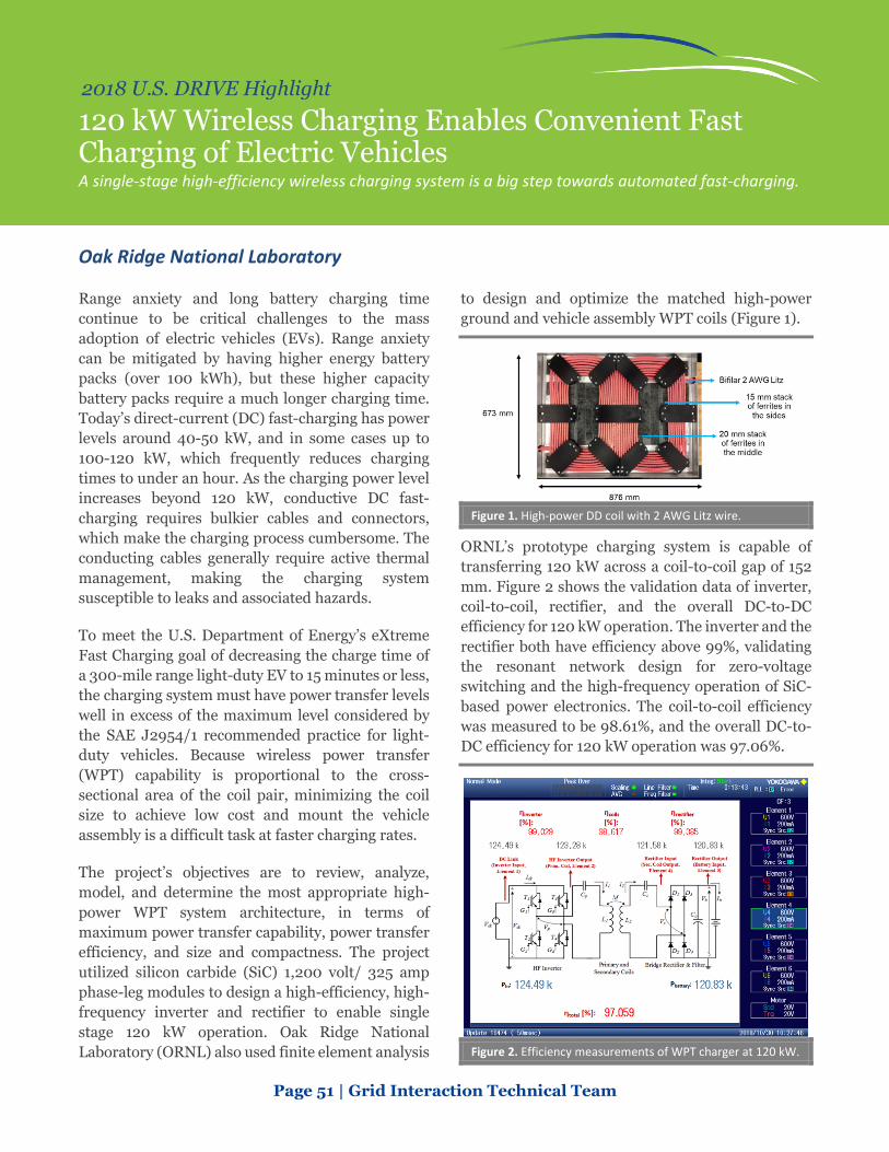
Page 51 | Grid Interaction Technical Team
2018 U.S. DRIVE Highlight
120 kW Wireless Charging Enables Convenient Fast Charging of Electric Vehicles A single-stage high-efficiency wireless charging system is a big step towards automated fast-charging.
Oak Ridge National Laboratory
Range anxiety and long battery charging time continue to be critical challenges to the mass adoption of electric vehicles (EVs). Range anxiety can be mitigated by having higher energy battery packs (over 100 kWh), but these higher capacity battery packs require a much longer charging time. Today’s direct-current (DC) fast-charging has power levels around 40-50 kW, and in some cases up to 100-120 kW, which frequently reduces charging times to under an hour. As the charging power level increases beyond 120 kW, conductive DC fast-charging requires bulkier cables and connectors, which make the charging process cumbersome. The conducting cables generally require active thermal management, making the charging system susceptible to leaks and associated hazards.
To meet the U.S. Department of Energy’s eXtreme Fast Charging goal of decreasing the charge time of a 300-mile range light-duty EV to 15 minutes or less, the charging system must have power transfer levels well in excess of the maximum level considered by the SAE J2954/1 recommended practice for light-duty vehicles. Because wireless power transfer (WPT) capability is proportional to the cross-sectional area of the coil pair, minimizing the coil size to achieve low cost and mount the vehicle assembly is a difficult task at faster charging rates.
The project’s objectives are to review, analyze, model, and determine the most appropriate high-power WPT system architecture, in terms of maximum power transfer capability, power transfer efficiency, and size and compactness. The project utilized silicon carbide (SiC) 1,200 volt/ 325 amp phase-leg modules to design a high-efficiency, high-frequency inverter and rectifier to enable single stage 120 kW operation. Oak Ridge National Laboratory (ORNL) also used finite element analysis
to design and optimize the matched high-power ground and vehicle assembly WPT coils (Figure 1).
Figure 1. High-power DD coil with 2 AWG Litz wire.
ORNL’s prototype charging system is capable of transferring 120 kW across a coil-to-coil gap of 152 mm. Figure 2 shows the validation data of inverter, coil-to-coil, rectifier, and the overall DC-to-DC efficiency for 120 kW operation. The inverter and the rectifier both have efficiency above 99%, validating the resonant network design for zero-voltage switching and the high-frequency operation of SiC-based power electronics. The coil-to-coil efficiency was measured to be 98.61%, and the overall DC-to-DC efficiency for 120 kW operation was 97.06%.
Figure 2. Efficiency measurements of WPT charger at 120 kW.

Page 52 | Grid Interaction Technical Team
2018 U.S. DRIVE Highlight
Customer Preference-Enabled Workplace Vehicle Charging with Building Integration Multi-lab development of a customer-focused charging control system can enhance the plug-in electric vehicle owner’s experience, incorporate renewables, and reduce building owners’ utility costs.
Pacific Northwest National Laboratory
Cost-effectively expanding plug-in electric vehicle (PEV) adoption through workplace charging requires that the building owner deliver enough charging energy to meet the transportation requirements of all vehicles, without incurring additional demand charges. The PEV owner may have personal preferences or transportation demands that conflict with electrical system or building constraints. Pacific Northwest National Laboratory developed a control algorithm to simultaneously meet multiple vehicle charging requirements, including mitigating demand charges and equitably sharing charging energy among all PEV charging, and meet three overarching customer provided preferences, “Fastest,” “Greenest,” and “Cheapest,” while using a photovoltaic (PV) energy supply to the building.
PEV charging can mitigate electrical distribution challenges resulting from adding PV generation to buildings by limiting export power in certain conditions. Figure 1 shows the controlled PEV charging load (purple line) and the total building load with PEV charging (blue line) using this algorithm. Most building load transients (brown line) are removed, solar power (yellow line) is incorporated into PEV charging, and building power remains below the demand charge limit (red line).
Figure 1. Preference-based PEV charging for demand mitigation.
The algorithm equitably divides the available charging power, PEV power (purple line), between the Fastest (black line), Greenest (green line), and Cheapest (red line) customer preference (Figure 2). Impacts from power fluctuations from PV power (yellow line) and uncontrolled PEV demand (grey line) were minimized.
Figure 2. Equitable available power sharing.
The power sharing algorithm allocated power among the three preference groups and 11 total cars by first calculating a priority for each vehicle using the vehicle battery’s state of charge (SOC), capacity, charging duration, and maximum charging power.
𝑃𝑃𝑃𝑃𝑃𝑃𝑃𝑃𝑃𝑃𝑃𝑃𝑃𝑃𝑃𝑃 = 𝑆𝑆𝑆𝑆𝑆𝑆 ∗ 𝑏𝑏𝑏𝑏𝑃𝑃𝑃𝑃𝑏𝑏𝑃𝑃𝑃𝑃 𝑐𝑐𝑏𝑏𝑐𝑐𝑏𝑏𝑐𝑐𝑃𝑃𝑃𝑃𝑃𝑃
𝑐𝑐ℎ𝑏𝑏𝑃𝑃𝑎𝑎𝑃𝑃𝑎𝑎𝑎𝑎 𝑑𝑑𝑑𝑑𝑃𝑃𝑏𝑏𝑃𝑃𝑃𝑃𝑃𝑃𝑎𝑎 ∗ 𝑐𝑐ℎ𝑏𝑏𝑃𝑃𝑎𝑎𝑃𝑃𝑎𝑎𝑎𝑎 𝑐𝑐𝑃𝑃𝑝𝑝𝑏𝑏𝑃𝑃
This priority value is then biased by customer preference. The approach distinguishes between Fastest, Greenest, and Cheapest vehicles by lengthening the charge time used by the control system. Fastest starts when plugged in at full charge rate (no delay), the Cheapest charging duration is multiplied by 10, and Greenest is tripled. The total priority is determined by summing all priorities and each car receives its share (Priority/Total Priority) of the available power. This approach was demonstrated in multiple PV, building load, and PEV charging scenarios and found to enable PV power to be effectively directed to PEV charging while accounting for customer preferences.

Hydrogen Codes and Standards

Page 54 | Hydrogen Codes and Standards Technical Team
2018 U.S. DRIVE Highlight
New Standards Developed for Hydrogen Compatibility of Polymeric Materials in the Infrastructure National laboratories and industry partnered to develop new standards and test methodologies that will help to improve polymer material durability and reliability for the hydrogen industry.
Pacific Northwest National Laboratory, Sandia National Laboratories, Oak Ridge National Laboratory, and Ford Motor CompanyIn 2018, Pacific Northwest National Laboratory, Sandia National Laboratories, Oak Ridge National Laboratory, and Ford teamed to close knowledge gaps and support hydrogen (H2) stakeholders in the proper selection of polymers for H2 applications. For the first time, standardized test methodologies and a database of material experimental results have been made available to the H2 design community to guide polymer material selection. Their aim is to improve safety and reduce development costs while accelerating the use of new materials to serve the growing H2 market. The team developed new tests and modified environmental conditions on existing tests by working with stakeholders and the CSA Group CHMC-2 committee. This work resulted in the new ANSI/CSA CHMC 2-2018 standard “Test methods for evaluating material compatibility in compressed hydrogen applications—Polymers,” currently under public review for release.
The standard’s scope is to provide uniform test methods for industry to compare polymer performance in H2 applications. The team advanced test methodologies from conceptual approaches to fully defined approaches and documented them for dissemination (Figure 1). The standards committee consisted of over 25 stakeholders from various parts of the H2 community. This document will provide a common framework for industry to consistently compare material performance. Such a framework has not previously existed, and its publication will help improve material durability and reliability in the H2 infrastructure.
Polymers are critical to H2 infrastructure applications. They reduce costs and complement metallic components with unique functionalities. However, unlike metals that have been studied extensively in high-pressure H2, there was a
significant knowledge gap in understanding polymer performance under these same conditions.
The lab team surveyed nearly 50 stakeholders ranging from material suppliers, component manufacturers, and H2 infrastructure consultants for feedback on the most common polymeric materials used, testing standards applied, challenges in material performance, and methods of disseminating information to the community. Survey results guided the subsequent material and test methodology focus.
The team developed a technical foundation to understand the effects of H2 on polymers. This enabled the development of appropriate test protocols for evaluating materials for H2 service. The team used model material systems to generate data in conjunction with test method development that helped the team understand the influence of material characteristics and characterize H2 effects.
Figure 1. Process in test methodology and document development.

Hydrogen Delivery

Page 56 | Hydrogen Delivery Technical Team
2018 U.S. DRIVE Highlight
Electrochemical Hydrogen Compressor Record-setting electrochemical hydrogen compression efficiency for 350-bar operation.
Giner ELX, Inc., National Renewable Energy Laboratory, Rensselaer Polytechnic Institute, and Gaia Energy Research Institute LLC.
In 2018, Giner ELX, Inc. completed experiments establishing that their electrochemical hydrogen compression (EHC) concept can achieve an efficiency of 2.7 kWh/kg, at an inlet pressure of 100 bar, outlet pressure of 350 bar, and current density of 1,000 mA/cm2. The energy consumption of their concept is half that of the previously known state of the art and represents a giant stride in enabling reliable hydrogen (H2) delivery with EHC technology.
H2 refueling stations, traditionally equipped with mechanical compressors, are on the rise in the United States, with the 39th station opening in California in 2018 and several stations planned in the Northeast corridor. However, one challenge with H2 refueling stations is that the mechanical compressors have high capital and maintenance costs. EHC technology, on the other hand, has the potential to achieve higher reliability than conventional mechanical compressors because it does not involve moving mechanical components. In the EHC process (Figure 1), low-pressure H2 gas is fed to the anode of an acidic electrolyte cell, where H2 gas is oxidized to form protons (H+) and electrons (e-). The protons are ionically transported across the electrolyte, in this case a polymer electrolyte membrane (PEM), to the cathode, where they are reduced, forming H2 at a higher pressure.
As shown in Figure 1, electrons move from the anode to the cathode through an external circuit and represent the electrical work needed to produce H2 at the higher pressure. Giner’s achievement is that it has reduced the voltage required for 350-bar compressors by 50% compared to the previously known state of the art, thus enhancing the efficiency of the EHC. Further, the PEM requires water to
transport H+ (electro-osmotically) and a significant innovation within Giner’s EHC concept is integrating a proprietary water management membrane (WAMM) to finely control the amount of water for operation. Additional innovations by Giner include developing a novel aromatic membrane that exhibits 30% less drag than conventional membranes and 50% less back-diffusion of H2. These novel membranes are being integrated with the WAMM and other supporting membranes to increase the stack’s mechanical strength, and manage water and temperature.
In 2019, Giner will focus on enhancing the durability of the EHC system components to achieve 875-bar compression of H2 at an efficiency of 4 kWh/kg. Compression to 875-bar (required for light-duty fuel cell vehicle refueling) can theoretically be achieved at less than 2 kWh/kg given an inlet pressure of 100 bar. EHC has the theoretical potential to achieve higher durability than mechanical compressors, at comparable efficiency.
Figure 1. Basic operating principle of EHC.

Page 57 | Hydrogen Delivery Technical Team
2018 U.S. DRIVE Highlight
Wireless, High-Accuracy Hydrogen Dispensers Using emerging secure wireless vehicle-dispenser communication methods and novel Coriolis meters to enhance the reliability and accuracy of hydrogen fueling.
IVYS Energy Solutions, Inc., Air Liquide Advanced Technologies U.S., Rheonik GmBH, and the National Renewable Energy Laboratory
A team lead by IVYS Energy Solutions, Inc. has developed a novel wireless approach that can enable reliable communication between fueling stations and vehicles, along with a high-accuracy hydrogen metering technology that exceeds the National Institute of Standards and Technology’s (NIST) standards (Handbook 44). Hydrogen fuel cell vehicles (FCVs) are currently filled per the SAE J2601 fueling protocol, which prescribes fill rates as a function of ambient temperature and vehicle state-of-charge. Infrared communications technologies are currently used to transmit data between a vehicle and the fueling station (e.g., tank volume, pressure, and temperature). Station communications technologies comply with the SAE J2799 standard. Additionally, meters are used to ensure the accuracy of fill amount.
Conventional Coriolis meters are challenged under the rapid fluctuations in temperature and pressure experienced during hydrogen fueling, particularly when fills have short durations. To date, challenges with communications and metering technologies are managed using non-communications fueling methods. Additionally, states and recent editions of the NIST Handbook 44 have adopted relaxed requirements for meter accuracy, of 5%. In the long term, reliable dispensing technologies are essential to ensure vehicles achieve the highest possible state-of-charge during fueling.
To enhance fueling accuracy and reliability, IVYS and partners developed: (1) wireless methods for vehicle-to-station communication, leveraging dedicated short-range communications (DSRC) technology that is currently being explored for other vehicle-to-infrastructure applications (e.g., crash avoidance, traffic data collection); and (2) a Coriolis
meter that has been enhanced with additional pressure and temperature sensors. The wireless technology developed can ultimately be used to reduce cost and complexity of stations by anticipating near-term station demand (through detection of vehicles arriving at the station), and thereby enabling optimization of station operation.
In 2018, researchers validated the performance of optimized Coriolis meters under a number of SAE J2601 refueling events. Results demonstrated repeatable accuracy of ≤ 2% with a 95% confidence interval over all conditions tested. In addition, vehicle-to-dispenser wireless communication (via DSRC) was validated at the bench scale. Over one million SAE J2799 messages (equivalent to 160 refueling events) were exchanged during testing with only 0.01% messages missed. All of the successfully received messages had zero errors and completed cyclic redundancy checks, exceeding requirements specified in SAE J2799. Following component testing, the design of a prototype intelligent dispenser system was completed.
Activities in 2019 include building the dispenser prototype and validating its performance at the National Renewable Energy Laboratory’s Hydrogen Infrastructure Testing and Research Facility.
Figure 1. Wireless hydrogen vehicle-to-station dispenser.

Hydrogen Production

Page 59 | Hydrogen Production Technical Team
2018 U.S. DRIVE Highlight
Platinum-Free Catalyst Outperforms Platinum for Microbial Electrolysis Hydrogen Production A molybdenum-phosphorous catalyst had higher activity and durability than platinum catalysts and a 5x improvement over platinum-free catalysts reported in the literature for microbial electrolysis.
Oregon State University and Pacific Northwest National Laboratory
Microbial processes utilizing biomass or waste streams have promise to enable affordable hydrogen (H2) production from diverse domestic feedstocks and energy resources. Fermentation is a low-temperature sustainable technology that has potential to achieve this goal. However, there are challenges: H2 yields are low, H2 production is slow and competes with methane production, and the product stream requires expensive cleanup due to other byproducts from fermentation. Microbial electrolysis cells (MECs) provide another opportunity for renewable H2 from biomass and waste streams. MECs are bio-electrochemical systems where an electrical current coupled with bacteria decompose organics to make H2. MEC’s challenges are using expensive platinum (Pt) as an electrode and low productivity. Because of these challenges, both of these promising technologies require early stage research and development.
One approach to overcoming these challenges is through a novel hybrid microbial electrochemical system that Oregon State University (OSU) developed.1 The design integrates fermentation and MEC into a single pot, which increases productivity—by enabling fermentation byproducts to be directly consumed by the MEC functionality, thus overcoming the limitations of a stand-alone fermentation reactor—while also lowering capital cost. OSU’s system has been demonstrated with glucose, lignocellulose hydrolysate, and wastewater.
In 2018, OSU and partner Pacific Northwest National Laboratory (PNNL) developed a new, extremely active and inexpensive molybdenum-phosphorous (MoP) catalyst for this reactor (Figure 1). The new catalyst eliminates Pt, reducing the capital cost of the system further, while producing
1 https://www.hydrogen.energy.gov/pdfs/review18/pd129_liu_2018_p.pdf.
more H2 than Pt under the same conditions. It is also five times more active than other Pt-free catalysts reported in the literature. With this catalyst, the hybrid MEC exceeded the project’s H2 production target by 2.5x, achieving 19L H2/L/day.
Figure 1. MoP catalyst exceeding Pt performance.
In addition, OSU made an important contribution to the fermentation process in general. OSU identified a low-cost additive (less than 5¢/kg H2) that effectively inhibits methane production, thus maximizing H2 production from the fermentation process.
The current projected H2 production cost for the hybrid MEC system with the additive to inhibit methane production and the low-cost, highly active MoP catalyst is ~$3.30/kg H2 using lignocellulosic hydrolysate and ~$2.20/kg H2 from a wastewater stream. The OSU-PNNL team believes it can decrease the H2 production cost even more to $2.90/kg H2 and $1.90/kg H2 with additional capital cost reduction. Assuming a credit for using wastewater, the H2 cost drops to less than $1/kg H2.

Integrated Systems Analysis

Page 61 | Integrated Systems Analysis Technical Team
2018 U.S. DRIVE Highlight
Automated Vehicles Can Reduce Greenhouse Gas Emissions by up to 50% A cradle-to-grave environmental analysis of automated vehicles with various levels of accessory loads.
Integrated Systems Analysis Technical Team
Automated vehicles (AVs) collect information from their surroundings using sensors and accessories. A control system interprets the information to safely and efficiently navigate the vehicle through its environment. AVs can enhance the mobility experience, reduce cost, and increase safety. SAE defines six levels of automation for AVs, spanning levels 0-5 (L0 to L5). Higher levels of automation, e.g., L4 and L5, where vehicles become more autonomous, acquire more sensory information and impose additional power load. The additional power load from automation accessories impacts the fuel economy of AVs. However, a driverless (L5) AV in a fully automated mobility system can be redesigned with much lighter weight and a more efficient powertrain with “smooth” driving patterns, thus improving its fuel economy compared to conventional non-automated vehicles.
The U.S. DRIVE Integrated Systems Analysis Technical Team (ISATT) evaluated the impacts of vehicle redesign and more efficient driving, increased vehicle miles travelled (VMT) over the vehicle’s lifetime, and various power loads of AV accessories on their environmental performance using a cradle-to-grave (C2G) analysis of a fully automated (L5), midsize internal combustion engine vehicle (ICEV). Based on recent literature, ISATT considered three possible automation power loads, 240 W, 600 W, and 2,000 W; a reduction in vehicle weight by 75%; and an increase in AV lifetime VMT to 500,000 (compared to 200,000 of a baseline conventional ICEV). ISATT expanded Argonne National Laboratory’s Greenhouse gas, Regulated Emissions, and Energy use in Transportation (GREET®) model to conduct C2G greenhouse gas (GHG) emissions analysis of AVs. The C2G analysis in GREET included energy use and emissions for both fuel and vehicle cycles. The fuel cycle includes
fuel production and fuel consumption during vehicle operation, and the vehicle cycle includes acquisition of vehicle materials, vehicle manufacturing, and end of life disposal and recycling of vehicle components.
Figure 1 shows C2G GHG emissions of a baseline conventional midsize car ICEV, and impacts from AV power load (240 W), vehicle redesign (75% weight decrease), increased lifetime VMT (500,000), and AVs with power loads of 600 and 2,000 W. Fuel economy improvement associated with vehicle redesign more than offsets the impact of fuel economy reduction due to AV power loads. AVs can reduce C2G GHG emissions, compared to a baseline conventional ICEV, by 50%, 45% and 25% for AV loads of 240, 600 and 2,000 W, respectively (Figure 1). Most of the improvement in the environmental performance of AVs will be realized through vehicle redesign. While the impact of AV power load on fuel cycle GHG emissions can be significant, its impact on vehicle cycle is not significant. The increased AV lifetime VMT significantly decreases vehicle cycle GHG emissions.
Figure 1. C2G GHG emissions of a midsize car AV showing the impacts of vehicle redesign, lifetime VMT, and AV power loads.

Page 62 | Integrated Systems Analysis Technical Team
2018 U.S. DRIVE Highlight
Battery Manufacturing and Charging Infrastructure Support Widescale Electric Vehicle Use without Major Grid Impact A series of first-order analytical estimates offers context for electric vehicles at scale.
Integrated Systems Analysis Technical Team
Electric vehicles (EVs) can power U.S. personal transportation using domestic energy resources and offer local air pollutant benefits. However, widescale EV use could entail special considerations for battery manufacturing, charging infrastructure, and the electric grid. Using a range of EV market penetration scenarios from the Electric Power Research Institute, the U.S. DRIVE Integrated Systems Analysis Technical Team (ISATT) performed a series of analyses to yield first-order estimates of such impacts.
U.S. EV production will require additional battery manufacturing beyond current domestic capacity (18 GWh commissioned/48 GWh total announced in 2017) to support EVs in a “most likely” projected market penetration: 14 million vehicles on the road in 2030. ISATT estimates such additional capacity corresponds to the equivalent of an additional 1-3 Gigafactories at an investment of $40-$70 billion. For a largest-projected market (40 million vehicles in 2030), that estimate roughly triples; whereas, for a smallest-market case (3 million vehicles in 2030), current capacity is sufficient.
Similarly, greater EV use requires additional non-residential EV charging infrastructure support. According to the National Renewable Energy Laboratory’s Plug-In Vehicle Infrastructure tool, approximately 560,000 Level 2 and 24,000 direct-current fast-chargers—both strategically spread across cities, towns, rural areas, and interstate corridors—could provide sufficient recharging opportunities to satisfy the charging needs of 14 million EVs. These estimates are most heavily dependent on assumed EV market size: increasing or decreasing the projected market increases or decreases, respectively, the charging needs roughly proportionally. Other important assumptions
include vehicles’ electric range, the amount of charging done at home, and the relative number and charging behavior of plug-in hybrid electric vehicles.
Finally, the grid is expected to be able to support a growing EV fleet as that grid evolves over time. A comparison of the amount of new generation and capacity needed for 2 million new EVs in 2030 (consistent with the 14 million EVs total scenario at that time) offers illustrative context that the grid can keep up. As Figure 1 shows, data since 2000 show the grid has added new generation and capacity from one year to the next equivalent to as many as 50-to-60 million EVs per year (assuming an EV requires roughly 3,500 kWh of energy each year and, in general, 1 kW relative to the peak for charging demand), 25-30 times the “most likely” projected market penetration studied here. Managed charging offers utilities additional flexibility in accommodating EV demand. It should be noted that distribution impacts may present additional costs; however, lower power and modest management efforts can reduce these costs, and subsequent revenues are expected to exceed costs except in the case of high power (greater than 10–15 kW).
Figure 1. Grid capacity installations over time versus equivalent need for 320k, 2 million, and 7 million new-EVs market scenarios.
