page intentionally left blankxsteel girder bridge xconcrete girder bridge (pre-stressed or...
TRANSCRIPT


PAGE INTENTIONALLY LEFT BLANK
IDAHO MANUAL FOR BRIDGE EVALUATION
ABBREVIATED TABLE OF CONTENTS
SECTION 1: INTRODUCTION
SECTION 4: INSPECTION
SECTION 6: LOAD RATING
IMBE Revision History
IMBE First Edition Published December 2013
IMBE 2015 Edition Published December 2014
IMBE 2016 Edition Published February 2016
IMBE 2018 Edition Published December 2017

PAGE INTENTIONALLY LEFT BLANK
IDAHO MANUAL FOR BRIDGE EVALUATIONSECTION 1: INTRODUCTION
TABLE OF CONTENTS
1-i
1.1—PURPOSE...................................................................................................................................................................... 1 1.4—QUALITY MEASURES................................................................................................................................................ 1
1.4.1—Introduction............................................................................................................................................................. 1 1.4.2—Definitions............................................................................................................................................................... 1 1.4.3—Quality Review Procedures for ITD Bridge Section Performed Inspections .......................................................... 2 1.4.4—Quality Review Procedures for Bridge Inspections Performed by Consultants...................................................... 3 1.4.5—Quality Review Procedures for Load Rating .......................................................................................................... 4 1.4.6—Qualifications of Personnel ..................................................................................................................................... 5 1.4.7—Personnel Files ........................................................................................................................................................ 5 1.4.8—Continued Training Requirements .......................................................................................................................... 5 1.4.9—Reference Manuals and Publications ...................................................................................................................... 6

1-ii IDAHO MANUAL FOR BRIDGE EVALUATION
PAGE INTENTIONALLY LEFT BLANK
IDAHO MANUAL FOR BRIDGE EVALUATIONSECTION 1:
INTRODUCTION
1-1
1.1—PURPOSE
The Idaho Manual for Bridge Evaluation (IMBE) is written as a supplement to the AASHTO Manual for Bridge Evaluation (MBE) Second Edition 2011. The IMBE is not intended to override information in the MBE; it is intended to provide supplemental information specific to the State of Idaho. The section/article headings in this manual match the section/article headings in the MBE. Gaps in the sequencing of sections and articles occur due to the MBE providing sufficient guidance resulting in no need to provide supplemental information specific to Idaho.
1.4—QUALITY MEASURES
1.4.1—Introduction
In order to insure that Idaho’s bridges are being inspected and data is gathered in an accurate and consistent manner, it is necessary to implement quality control and quality assurance plans. Accuracy and consistency of the data is important since the bridge inspection process is the foundation of the entire bridge management operation. The accuracy and consistency of the inspection and documentation is vital because it not only impacts programming and funding appropriations, it also affects public safety.
These procedures are intended to maintain the quality of Idaho Transportation Department (ITD) bridge inspection and load rating at or above a specified level. These are daily functions of persons performing safety inspections or load ratings, including consultants. These procedures will provide for uniformity and consistency among the numerous personnel responsible for bridge inspection and load rating.
1.4.2—Definitions
Bridge Asset Management Engineer (BAME) - ITD person in charge of the National Bridge Inspection Standards (NBIS) program who has been assigned or delegated the duties and responsibilities for bridge inspection, reporting, inventory, and load rating. The BAME provides overall leadership and is available to bridge inspectors, load rating engineers, database managers, consultants, and equipment specialists to provide guidance. The BAME is responsible for the bridge inspection program statewide.
Bridge Inspector - ITD personnel in charge of a bridge inspection team (NBIS Team Leader), is responsible for planning, preparing, and performing field inspections. The Bridge Inspector is responsible for the overall management/supervision of an inspection team composed of one or more inspectors. The Bridge Inspector assures that inspections within thejurisdiction of the team are performed on-time and in accordance with the NBIS and ITD’s current policies and procedures.
Bridge Inspector’s Reference Manual (BIRM) - An FHWA publication that explains the basic concepts of bridge inspection and requirements of the National Bridge Inspection Standards.
Bridge Inspector Trainee - An individual who assists a Bridge Inspector with the inspection of a structure.
Consultant Bridge Inspector - Personnel hired by ITD to act as a Bridge Inspector on behalf of ITD.
Consultant Load Rating Engineer - Personnel hired by ITD to act as a Load Rating Engineer on behalf of ITD
Database Manager – ITD personnel in charge of maintaining and updating the central bridge files and the BrM™ Bridge Management System in accordance with ITD’s current policies and procedures.
1-2 IDAHO MANUAL FOR BRIDGE EVALUATION
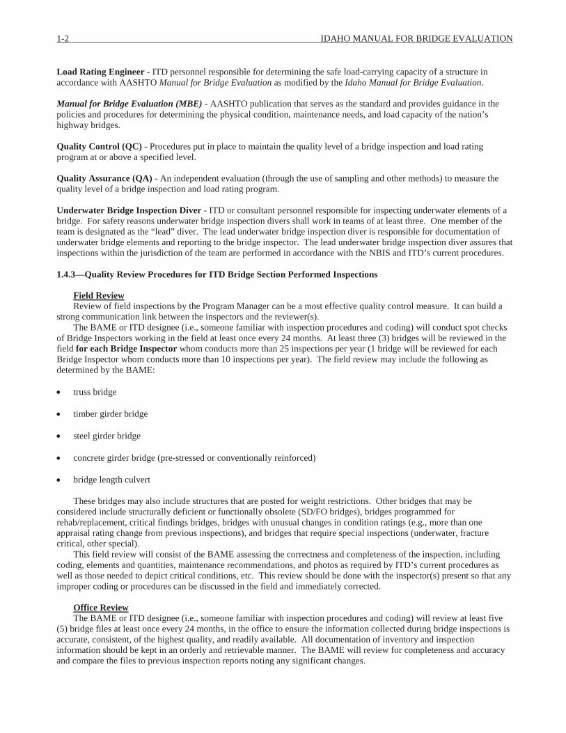
Load Rating Engineer - ITD personnel responsible for determining the safe load-carrying capacity of a structure in accordance with AASHTO Manual for Bridge Evaluation as modified by the Idaho Manual for Bridge Evaluation.
Manual for Bridge Evaluation (MBE) - AASHTO publication that serves as the standard and provides guidance in the policies and procedures for determining the physical condition, maintenance needs, and load capacity of the nation’s highway bridges.
Quality Control (QC) - Procedures put in place to maintain the quality level of a bridge inspection and load rating program at or above a specified level.
Quality Assurance (QA) - An independent evaluation (through the use of sampling and other methods) to measure the quality level of a bridge inspection and load rating program.
Underwater Bridge Inspection Diver - ITD or consultant personnel responsible for inspecting underwater elements of a bridge. For safety reasons underwater bridge inspection divers shall work in teams of at least three. One member of the team is designated as the “lead” diver. The lead underwater bridge inspection diver is responsible for documentation of underwater bridge elements and reporting to the bridge inspector. The lead underwater bridge inspection diver assures that inspections within the jurisdiction of the team are performed in accordance with the NBIS and ITD’s current procedures.
1.4.3—Quality Review Procedures for ITD Bridge Section Performed Inspections
Field ReviewReview of field inspections by the Program Manager can be a most effective quality control measure. It can build a
strong communication link between the inspectors and the reviewer(s).The BAME or ITD designee (i.e., someone familiar with inspection procedures and coding) will conduct spot checks
of Bridge Inspectors working in the field at least once every 24 months. At least three (3) bridges will be reviewed in the field for each Bridge Inspector whom conducts more than 25 inspections per year (1 bridge will be reviewed for each Bridge Inspector whom conducts more than 10 inspections per year). The field review may include the following as determined by the BAME:
truss bridge
timber girder bridge
steel girder bridge
concrete girder bridge (pre-stressed or conventionally reinforced)
bridge length culvert
These bridges may also include structures that are posted for weight restrictions. Other bridges that may be considered include structurally deficient or functionally obsolete (SD/FO bridges), bridges programmed for rehab/replacement, critical findings bridges, bridges with unusual changes in condition ratings (e.g., more than oneappraisal rating change from previous inspections), and bridges that require special inspections (underwater, fracture critical, other special).
This field review will consist of the BAME assessing the correctness and completeness of the inspection, including coding, elements and quantities, maintenance recommendations, and photos as required by ITD’s current procedures as well as those needed to depict critical conditions, etc. This review should be done with the inspector(s) present so that any improper coding or procedures can be discussed in the field and immediately corrected.
Office ReviewThe BAME or ITD designee (i.e., someone familiar with inspection procedures and coding) will review at least five
(5) bridge files at least once every 24 months, in the office to ensure the information collected during bridge inspections isaccurate, consistent, of the highest quality, and readily available. All documentation of inventory and inspection information should be kept in an orderly and retrievable manner. The BAME will review for completeness and accuracy and compare the files to previous inspection reports noting any significant changes.
SECTION 1: INTRODUCTION 1-3
As necessary, the BAME will review the need to rotate inspection teams including consultants between the Districts.
1.4.4—Quality Review Procedures for Bridge Inspections Performed by Consultants
The BAME may delegate the Quality Review procedure of Consultant Bridge Inspectors working in their districts to the Bridge Inspectors, to ensure the quality is acceptable. Consultants are responsible for internal QC/QA controls within their own organization and should be aligned with the QC/QA procedures described in this manual.
Field ReviewThe Bridge Inspector will conduct spot checks of Consultant Bridge Inspectors working in the field at least once every
24 months. The Bridge Inspector will randomly choose at least five (5) bridges to review in the field for each Consultant Bridge Inspector. These bridges will typically have been previously inspected by said Consultant Bridge Inspector. The composition of these five bridges will be such that they represent a cross-section of bridge types inspected. It is strongly recommended that they include one of each of the following:
truss bridge
timber girder bridge
steel girder bridge
concrete girder bridge (pre-stressed or conventionally reinforced)
bridge length culvert
Two (2) of these representative bridges will include bridges that are posted for weight restrictions (if available in the bridges area assigned to the Consultant Bridge Inspector). Other bridges to be considered may include structurally deficient bridges, functionally obsolete bridges, bridges programmed for rehab/replacement, critical findings bridges, bridges with unusual changes in condition ratings (e.g., more than one appraisal rating change from previous inspections), and bridges that require special inspections (underwater, fracture critical, other special).
This field review will consist of the Bridge Inspector assessing the correctness and completeness of the inspection, including coding, elements and quantities, maintenance recommendations, and photos as required by ITD’s latest policies and procedures as well as those needed to depict critical conditions, etc. This review should be done with the Consultant Bridge Inspector(s) present so that any improper coding or procedures can be discussed in the field and immediately corrected.
Office ReviewThe Bridge Inspector and/or the Database Manager will review all consultant bridge inspection reports to ensure the
information collected during bridge inspections is accurate, consistent, and of the highest quality. Among items to be reviewed are:
the appropriateness of the identified BrM™ elements and their approximate quantities
all necessary BrM™ element defects have been identified and properly coded
the correlation between spread of BrM™ condition states and the NBIS coding
work candidates, if needed, are present and appropriate
load restrictions, if present, correlate with load rating and recommended posting
all required photos are attached
the “wearing surface/dead load” does not exceed “max wearing surface for load capacity” by more than ½ inch

1-4 IDAHO MANUAL FOR BRIDGE EVALUATION
all items necessary for accurate reporting to the NBI are properly coded
any significant changes from the previous inspection reports
file documentation is sufficient
bridge owner was notified of any critical findings and the follow up documentation was received to indicate the critical finding has been resolved.
The Database Manager will make completed consultant bridge inspection reports readily available.
DisqualificationWhen the inspection review indicates that a consulting firm and/or Consultant Bridge Inspector continue to make the
same or similar mistakes, omissions, etc., ITD may implement disqualification procedures as follows:Upon receiving notice of incorrect coding and significant findings, the Consultant Bridge Inspector shall address the
findings and prepare a report which explains the steps that will be taken to correct the problems to insure they will not be repeated in the future.
The Consultant Bridge Inspector will be placed on probation and reviewed again in three months. This review will be conducted by a team consisting of the Consultant Bridge Inspector, the (ITD) Bridge Inspector, and the BAME. A member of the FHWA also may attend the review if they desire.
If the same or similar mistakes are found during this second review, the Consultant Bridge Inspector shall be given notification that they will be disqualified if these problems are not corrected and avoided in the future, and placed on a secondary probation period of three months.
The Consultant Bridge Inspector shall be reviewed again in three months by the reviewing team. If the same or similar problems are found, the Consultant Bridge Inspector and/or consulting firm will be notified that they are hereby disqualified for a minimum of two years.
A disqualified Consultant Bridge Inspector and/or firm may be re-qualified after the two-year period if they indicate in their term agreement proposal how they have corrected their deficiencies, i.e. refresher training, change in personnel, etc.
Reasons for DisqualificationTypical reasons for disqualification can be, but are not limited to, the following:
lack of proper contact with the bridge owner after finishing inspections in the area
lack of proper follow-up with the bridge owner for critical findings
failure to report significant deterioration or damage such as fractured load-carrying members, critical scour at foundations, and vehicular impacts
failure to perform bridge inspections and produce inspection reports on time
failure to attend training provided by ITD
1.4.5—Quality Review Procedures for Load Rating
An initial rating will be done based on the as-built condition of the bridge for every state and local bridge in accordance with AASHTO Manual for Bridge Evaluation as modified by the Idaho Manual for Bridge Evaluation and AASHTO LRFD Bridge Design Specifications as modified by the Bridge Design LRFD Manual. Once the initial rating is done the rating will be modified to reflect any changes in condition of the bridge or dead load applied. These changes will be brought to the attention of the Load Rating Engineer by review of the bridge inspection reports.
The following procedures shall apply for all load ratings done by ITD personnel; procedures for consultants may vary per the consultant agreement:

SECTION 1: INTRODUCTION 1-5
RaterAll the data available for the structure to be load rated shall be collected and reviewed for completeness and accuracy.
The inspection report and photos will be compared to any plans or sketches to ensure they are for the bridge in place. The load rating will be based on the current loads on the bridge. The rater will generate a computer file for the bridge and fillout an ITD Load Rating Summary Form (LRS).
CheckerThe checker will review all the available data for the bridge and check the rater’s conclusions for current loads. The
input for the load rating computer file will be confirmed by the checker and the file will be run to confirm the output. Allinformation on the LRS will be checked for completeness and accuracy. The computer file and LRS along with any comments are returned to the rater for correction, or a stamp and signature.
QC/QAOnce the rater and checker have a completed checked rating, the computer file and LRS will be submitted to the
QC/QA person for review. The ITD Quality Assurance Checklist (internal ITD document only) will be filled out for the load rating. If there are any comments, the rating goes back to the rater for correction. Once the QC/QA person determines the computer file and LRS form are correct, the rating information is input into the BrM™ database, a hard copy of the LRS form is put in the bridge file, and the computer model is put into use for the analysis of overweight permit vehicles. Additional QC/QA information for the load rating analysis can be found in Section 6 of this manual.
1.4.6—Qualifications of Personnel
See Article 4.4 for detailed qualifications of personnel.
1.4.7—Personnel Files
Personnel qualifications are maintained in ITD central HR files. HR files contain:
years, position title, and responsible duties
training completed
certifications/registrations
1.4.8—Continued Training Requirements
The Program Manager and Bridge Inspectors (ITD and Consultant) must take at least one training course every four years. Training courses may be scheduled by the Bridge Asset Management Engineer as budget considerations allow.Suggested topics include:
any NHI training courses, these may be rotated over several inspection cycles to cover all topics
Bridge Inspection Refresher Training
Engineering Concepts for Bridge Inspectors
Safety Inspection of In-Service Bridges
Fracture Critical Inspection Techniques for Steel Bridges
Inspection of Ancillary Highway Structures
Underwater Bridge Inspection
OSHA Confined Space Training

1-6 IDAHO MANUAL FOR BRIDGE EVALUATION
Specialized Equipment Training
other safety training
1.4.9—Reference Manuals and Publications
As can be true with any inspection, specific problems not covered in these general procedures may be encountered. If that is the case, the inspector will want to refer to manuals which describe special inspection procedures and equipment needs in greater detail.
Suggestions are:
Idaho Bridge Inspection Coding Guide
FHWA Recording and Coding Guide for the Structure Inventory and Appraisal of the Nations Bridges
AASHTO The Manual for Bridge Evaluation (MBE)
NHI Bridge Inspector’s Reference Manual (BIRM)
AASHTO Manual for Bridge Element Inspection
FHWA Inspection of Fracture Critical Bridge Members
HEC 18 Evaluating Scour at Bridges
HEC 20 Stream Stability at Highway Structures
HEC 23 Bridge Scour and Stream Instability Countermeasures Experience, Selection, and Design Guidance
FHWA Guidelines for the Installation, Inspection, Maintenance and Repair of Structural Supports for Highway Signs, Luminaries, and Traffic Signals
If the inspector does not find the guidance needed, the concern should be brought to the attention of the BAME.Consultant Bridge Inspectors should contact the Bridge Inspector responsible for the area they are working in.
IDAHO MANUAL FOR BRIDGE EVALUATIONSECTION 4: INSPECTION
TABLE OF CONTENTS
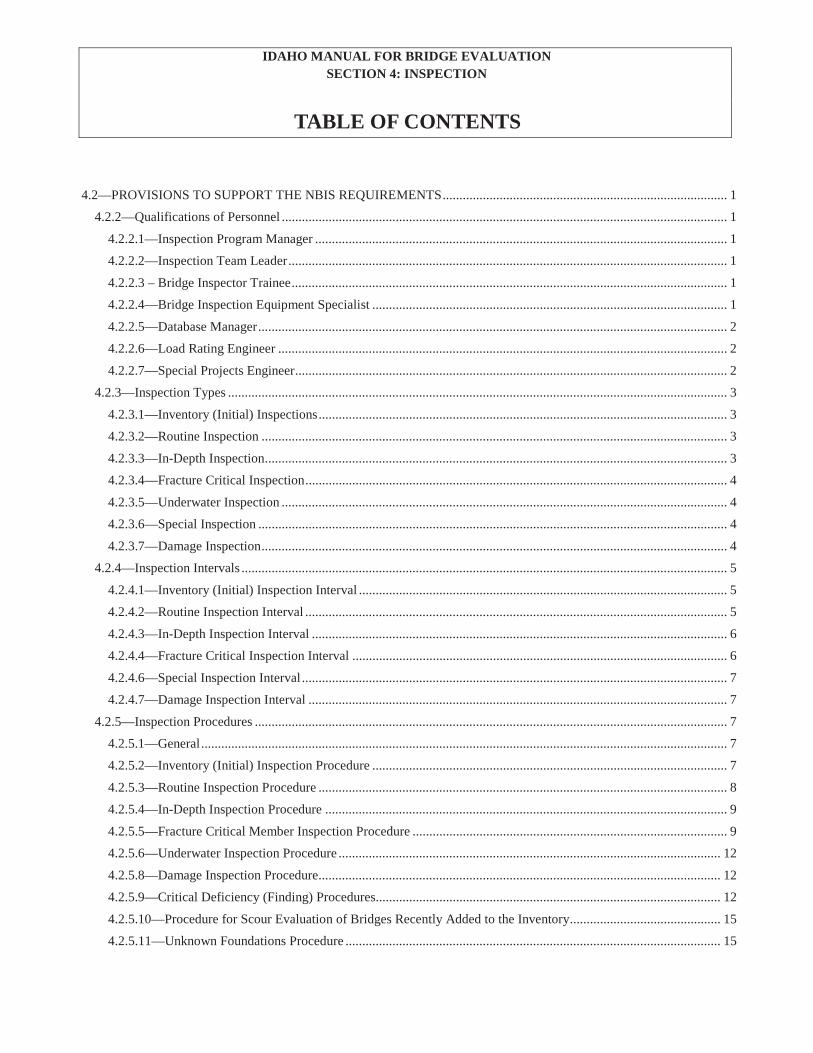
4.2—PROVISIONS TO SUPPORT THE NBIS REQUIREMENTS..................................................................................... 1
4.2.2—Qualifications of Personnel ..................................................................................................................................... 1 4.2.2.1—Inspection Program Manager ........................................................................................................................... 1 4.2.2.2—Inspection Team Leader................................................................................................................................... 1 4.2.2.3 – Bridge Inspector Trainee.................................................................................................................................. 1 4.2.2.4—Bridge Inspection Equipment Specialist .......................................................................................................... 1 4.2.2.5—Database Manager............................................................................................................................................ 2 4.2.2.6—Load Rating Engineer ...................................................................................................................................... 2 4.2.2.7—Special Projects Engineer................................................................................................................................. 2
4.2.3—Inspection Types ..................................................................................................................................................... 3 4.2.3.1—Inventory (Initial) Inspections.......................................................................................................................... 3 4.2.3.2—Routine Inspection ........................................................................................................................................... 3 4.2.3.3—In-Depth Inspection.......................................................................................................................................... 3 4.2.3.4—Fracture Critical Inspection.............................................................................................................................. 4 4.2.3.5—Underwater Inspection ..................................................................................................................................... 4 4.2.3.6—Special Inspection ............................................................................................................................................ 4 4.2.3.7—Damage Inspection........................................................................................................................................... 4
4.2.4—Inspection Intervals ................................................................................................................................................. 5 4.2.4.1—Inventory (Initial) Inspection Interval .............................................................................................................. 5 4.2.4.2—Routine Inspection Interval .............................................................................................................................. 5 4.2.4.3—In-Depth Inspection Interval ............................................................................................................................ 6 4.2.4.4—Fracture Critical Inspection Interval ................................................................................................................ 6 4.2.4.6—Special Inspection Interval ............................................................................................................................... 7 4.2.4.7—Damage Inspection Interval ............................................................................................................................. 7
4.2.5—Inspection Procedures ............................................................................................................................................. 7 4.2.5.1—General............................................................................................................................................................. 7 4.2.5.2—Inventory (Initial) Inspection Procedure .......................................................................................................... 7 4.2.5.3—Routine Inspection Procedure .......................................................................................................................... 8 4.2.5.4—In-Depth Inspection Procedure ........................................................................................................................ 9 4.2.5.5—Fracture Critical Member Inspection Procedure .............................................................................................. 9 4.2.5.6—Underwater Inspection Procedure .................................................................................................................. 12 4.2.5.8—Damage Inspection Procedure........................................................................................................................ 12 4.2.5.9—Critical Deficiency (Finding) Procedures....................................................................................................... 12 4.2.5.10—Procedure for Scour Evaluation of Bridges Recently Added to the Inventory............................................. 15 4.2.5.11—Unknown Foundations Procedure ................................................................................................................ 15
4-ii IDAHO MANUAL FOR BRIDGE EVALUATION
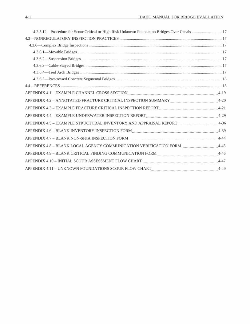
4.2.5.12 – Procedure for Scour Critical or High Risk Unknown Foundation Bridges Over Canals ............................. 17 4.3—NONREGULATORY INSPECTION PRACTICES ................................................................................................... 17
4.3.6—Complex Bridge Inspections ................................................................................................................................. 17 4.3.6.1—Movable Bridges ............................................................................................................................................ 17 4.3.6.2—Suspension Bridges ........................................................................................................................................ 17 4.3.6.3—Cable-Stayed Bridges..................................................................................................................................... 17 4.3.6.4—Tied Arch Bridges.......................................................................................................................................... 17 4.3.6.5—Prestressed Concrete Segmental Bridges ....................................................................................................... 18
4.4—REFERENCES ............................................................................................................................................................ 18 APPENDIX 4.1 – EXAMPLE CHANNEL CROSS SECTION 4-19
APPENDIX 4.2 – ANNOTATED FRACTURE CRITICAL INSPECTION SUMMARY 4-20
APPENDIX 4.3 – EXAMPLE FRACTURE CRITICAL INSPECTION REPORT 4-21
APPENDIX 4.4 – EXAMPLE UNDERWATER INSPECTION REPORT 4-29
APPENDIX 4.5 – EXAMPLE STRUCTURAL INVENTORY AND APPRAISAL REPORT 4-36
APPENDIX 4.6 – BLANK INVENTORY INSPECTION FORM 4-39
APPENDIX 4.7 – BLANK NON-SI&A INSPECTION FORM 4-44
APPENDIX 4.8 – BLANK LOCAL AGENCY COMMUNICATION VERIFICATION FORM 4-45
APPENDIX 4.9 – BLANK CRITICAL FINDING COMMUNICATION FORM 4-46
APPENDIX 4.10 – INITIAL SCOUR ASSESSMENT FLOW CHART 4-47
APPENDIX 4.11 – UNKNOWN FOUNDATIONS SCOUR FLOW CHART 4-49

IDAHO MANUAL FOR BRIDGE EVALUATIONSECTION 4:
INSPECTION
4.2—PROVISIONS TO SUPPORT THE NBIS REQUIREMENTS
4.2.2—Qualifications of Personnel
Responsibilities of Inspection Personnel may vary due to section needs and staffing availability. Duties not covered by the CFR may be switched as necessary and new duties may be assigned as allowed in the ITD Human Resources Employee Policy & Procedure Handbook.
4.2.2.1—Inspection Program Manager
The Bridge Asset Management Engineer (BAME) is the inspection program manager and meets all qualification requirements specified in 23 CFR 650.309. The BAME is responsible for Idaho’s compliance with the National Bridge Inspection Standards which include the inspections, load ratings, and scour evaluations of all bridges in Idaho. The BAME is also responsible for the analyses of state bridges for over legal truck loads.
The BAME manages a staff which includes state bridge inspectors, load rating engineers, a special projects engineer, and a bridge inspection equipment specialist. The BAME or designee also administers contracts with local bridge inspection consultants, and load rating consultant engineers.
4.2.2.2—Inspection Team Leader
Staff Inspectors meet the qualification requirements for team leader specified in 23 CFR 650.309 and are responsible for the inspection of state bridges. Staff Inspectors are centralized at the Boise headquarters and travel to their respective areas.
ITD contracts with 7-10 consultants to inspect locally-owned bridges throughout the state. These contracts are negotiated annually with qualified firms from ITD’s term agreement list. All consultants are qualified as team leaders according to 23 CFR 650.309. The consultant inspection areas typically follow county lines.
Inspectors are responsible for the inventory, routine, fracture critical, underwater, complex, damage and all special inspections of the bridges in their areas. ITD presently is a licensee of BrM™ and inspectors use this software for all data collection and reporting. The state bridge inspectors are responsible for the consultant prepared inspection reports of areas in their districts.
ITD contracts with a firm to perform the underwater inspections for all state and local bridges whose foundations cannot be inspected and evaluated during a routine inspection.
4.2.2.3 – Bridge Inspector Trainee
The trainee position gives an individual the experience necessary to meet the requirements of team leader as specified in 23 CFR 650.309. Experience is gained by successfully completing required training and assisting the team leaders with performing routine, fracture critical, in-depth, and other inspection types. The inspector trainee, after gaining experience, is also responsible for the inventory, inspection and reporting of the short-span bridges. These are structures on the state system with lengths greater than or equal to 10 feet but less than or equal to 20 feet.
4.2.2.4—Bridge Inspection Equipment Specialist
The Bridge Inspection Equipment Specialist (BIES) is responsible for the operation and maintenance of ITD’s under-bridge inspection truck (UBIT). This includes all maintenance, repairs and inspections of the boom and the UBIT itself. The BIES shall maintain all records showing maintenance and inspections of the UBIT. This position also makes sure all equipment required for inspections is maintained and is in working order. The BIES shall make recommendation(s) for the purchase of new equipment.
The BIES is responsible for scheduling the UBIT with the state inspectors and consultant inspectors, making every effort to coordinate the truck with the inspection due date. This position is responsible for scheduling the truck with outside agencies and all contractual documents required by ITD for use of the truck, other equipment and additional inspection personnel.
4-2 IDAHO MANUAL FOR BRIDGE EVALUATION
4.2.2.5—Database Manager
ITD uses an Oracle database with BrM™. The database manager is responsible for the accuracy and integrity of the items required by the NBI, additional Idaho specific items, and element data for all bridges in Idaho. The database manager is also responsible for the yearly update to the NBI of Idaho’s bridge data.
Additional responsibilities of this position include:
creating reports for ITD management, other sections and outside agencies requesting bridge data
testing new versions of the BrM™ software
troubleshooting and responding to users’ questions regarding BrM™
coordinate data from ITD and consultant inspectors
assigning permissions to users for access to bridge data
overseeing the Critical Findings process
overseeing the posting & closing of bridges
quality assurance of inspection reports
4.2.2.6—Load Rating Engineer
All new bridges must be load rated according the procedures described in this manual and Articles 0.3 and 0.4 of the Bridge Design Manual. This as-built model provides a benchmark for future load ratings as the bridge deteriorates over time. Overlays, improvements, and deterioration may trigger a new load rating. Bridges are analyzed for live load carrying capacity.
ITD has a team of licensed engineers in BAM whose primary duties are load ratings. All meet the qualifications as specified in 23 CRF 650.309(c). Responsibilities include modeling the bridge in the AASHTOWare Bridge Ratingprogram (BrR™), analyzing the results, troubleshooting errors, and providing rating factors for the required trucks. All load ratings are checked by another engineer and QA’d before the electronic bridge model is finalized. Additionally, the load rating engineer fills out a load rating summary sheet for the bridge file and prepares posting letters for the BAME’s signature if load posting is required.
4.2.2.7—Special Projects Engineer
The special projects engineer has a variety of duties, including being the sentinel for the BridgeWatch™ system. This person is responsible for evaluating and responding to alerts from the system, working with the contractor to ensure that all scour critical and high risk unknown foundation bridges are in the system and advising the scour committee of changes or adjustments necessary so that personnel can respond to alerts in a timely manner.
This position is responsible for maintaining the IMBE and ensuring that it is compatible with all updates to the MBE. This position also is part of the load rating staff and may be assigned other duties of the section that have to do with inspection, scour evaluation, and overweight permitting.
SECTION 4: INSPECTION 4-3
4.2.3—Inspection Types
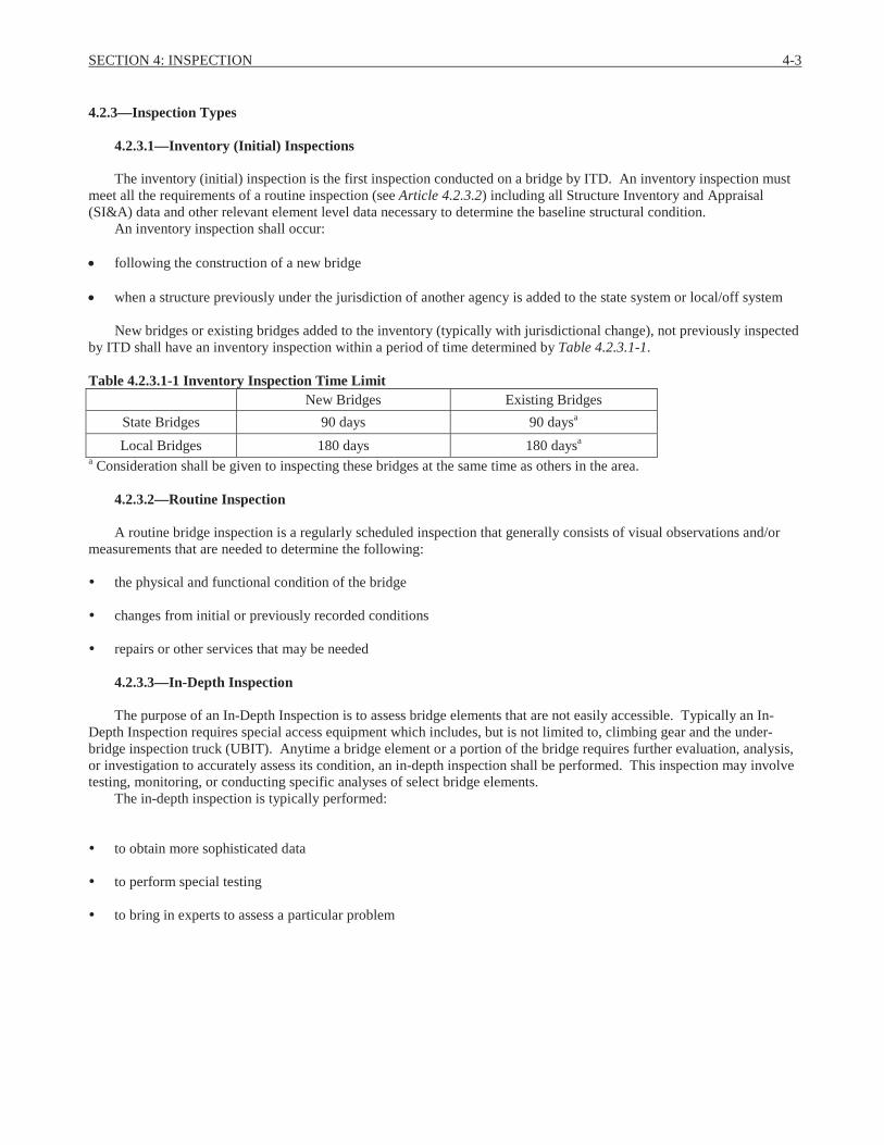
4.2.3.1—Inventory (Initial) Inspections
The inventory (initial) inspection is the first inspection conducted on a bridge by ITD. An inventory inspection must meet all the requirements of a routine inspection (see Article 4.2.3.2) including all Structure Inventory and Appraisal (SI&A) data and other relevant element level data necessary to determine the baseline structural condition.
An inventory inspection shall occur:
following the construction of a new bridge
when a structure previously under the jurisdiction of another agency is added to the state system or local/off system
New bridges or existing bridges added to the inventory (typically with jurisdictional change), not previously inspected by ITD shall have an inventory inspection within a period of time determined by Table 4.2.3.1-1.
Table 4.2.3.1-1 Inventory Inspection Time LimitNew Bridges Existing Bridges
State Bridges 90 days 90 daysa
Local Bridges 180 days 180 daysa
a Consideration shall be given to inspecting these bridges at the same time as others in the area.
4.2.3.2—Routine Inspection
A routine bridge inspection is a regularly scheduled inspection that generally consists of visual observations and/or measurements that are needed to determine the following:
the physical and functional condition of the bridge
changes from initial or previously recorded conditions
repairs or other services that may be needed
4.2.3.3—In-Depth Inspection
The purpose of an In-Depth Inspection is to assess bridge elements that are not easily accessible. Typically an In-Depth Inspection requires special access equipment which includes, but is not limited to, climbing gear and the under-bridge inspection truck (UBIT). Anytime a bridge element or a portion of the bridge requires further evaluation, analysis, or investigation to accurately assess its condition, an in-depth inspection shall be performed. This inspection may involve testing, monitoring, or conducting specific analyses of select bridge elements.
The in-depth inspection is typically performed:
to obtain more sophisticated data
to perform special testing
to bring in experts to assess a particular problem

4-4 IDAHO MANUAL FOR BRIDGE EVALUATION
4.2.3.4—Fracture Critical Inspection
A fracture critical member (FCM) is a steel member, in tension, that is not load path redundant. Fatigue is the primary cause of failure in fracture critical members. Failure of a FCM has the potential to cause the bridge to collapse.
The purpose of a fracture critical (FC) inspection is to identify and record the location of FCMs and any problems or potential problems at these locations in order to determine the safety of the structure. FC inspections provide a history of cracking (time of initiation, rate of growth, etc.) that can greatly assist the engineer in determining the need and priority of repairs and in estimating the remaining life of the bridge.
Fracture critical inspections are always done in conjunction with a routine inspection, the fracture critical inspection schedule and follow up procedures are part of the routine inspection report.
4.2.3.5—Underwater Inspection
If the underwater portion of a bridge substructure or the surrounding stream channel cannot be inspected visually at low water by wading or probing, it shall require an underwater inspection using divers or other appropriate techniques to accomplish these tasks. An inspection team leader must be present for all underwater inspections.
4.2.3.6—Special Inspection
Special inspections are performed to monitor known or suspected deficiencies. Special inspection reports shall clearly indicate what elements were looked at, what methods of inspection were used (visual, dye penetrant, ultrasonic, hands on,etc.), and what was found. Bridges meeting the following criteria may have special inspections:
Fatigue-prone details on steel girder bridges: Fatigue-prone details are category E or E’ details and fatigue to these details is typically caused by out of plane bending. Generally, the procedures for special inspections are the same as those for fracture critical.
Other defects: These are defects that are identified by the inspection team leader where additional monitoring may be needed. These defects should be documented in the inspection report and discussed with the BAME for concurrence to perform special inspections.
There is no unique report for special inspections. Conditions are included in the appropriate BrM™ element commentary. Repair recommendations are documented in the Maintenance Recommendations section of the report.
4.2.3.7—Damage Inspection
Damage inspections are unscheduled inspections required when a bridge has been damaged. A damage inspection must be conducted by an inspection team leader.
A damage inspection can occur following:
a vehicle striking the bridge
high water under the bridge
a severe environmental event such as an earthquake or tornado
4.2.3.7.1—Damage Assessments
Following notification of potential damage to a bridge, the BAME may request an onsite damage assessment be conducted by ITD personnel who are near the affected bridge. Damage assessors usually do not meet the requirements of an inspection team leader but serve an important role because they are often the first-responder(s) for the Department.
Measurements and photographs of damage may be required so that the BAME can determine:
whether or not to dispatch a bridge inspection team
if a bridge should be closed or restricted until bridge inspectors can get to the site and inspect the damage
No official report is required. A phone call or email to BAM staff is sufficient documentation of a damage assessment.
SECTION 4: INSPECTION 4-5
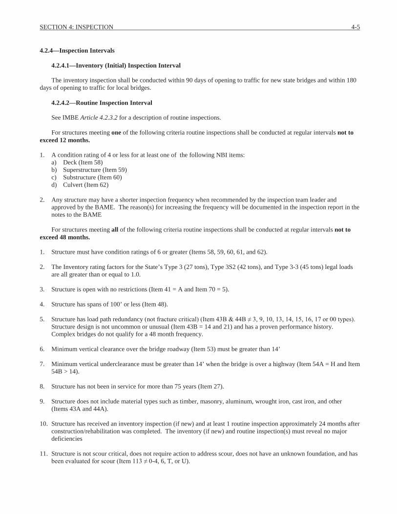
4.2.4—Inspection Intervals
4.2.4.1—Inventory (Initial) Inspection Interval
The inventory inspection shall be conducted within 90 days of opening to traffic for new state bridges and within 180 days of opening to traffic for local bridges.
4.2.4.2—Routine Inspection Interval
See IMBE Article 4.2.3.2 for a description of routine inspections.
For structures meeting one of the following criteria routine inspections shall be conducted at regular intervals not to exceed 12 months.
1. A condition rating of 4 or less for at least one of the following NBI items:a) Deck (Item 58) b) Superstructure (Item 59)c) Substructure (Item 60)d) Culvert (Item 62)
2. Any structure may have a shorter inspection frequency when recommended by the inspection team leader and approved by the BAME. The reason(s) for increasing the frequency will be documented in the inspection report in the notes to the BAME
For structures meeting all of the following criteria routine inspections shall be conducted at regular intervals not to exceed 48 months.
1. Structure must have condition ratings of 6 or greater (Items 58, 59, 60, 61, and 62).
2. The Inventory rating factors for the State’s Type 3 (27 tons), Type 3S2 (42 tons), and Type 3-3 (45 tons) legal loads are all greater than or equal to 1.0.
3. Structure is open with no restrictions (Item 41 = A and Item 70 = 5).
4. Structure has spans of 100’ or less (Item 48).
5. Structure has load path redundancy Structure design is not uncommon or unusual (Item 43B = 14 and 21) and has a proven performance history. Complex bridges do not qualify for a 48 month frequency.
6. Minimum vertical clearance over the bridge roadway (Item 53) must be greater than 14’
7. Minimum vertical underclearance must be greater than 14’ when the bridge is over a highway (Item 54A = H and Item 54B > 14).
8. Structure has not been in service for more than 75 years (Item 27).
9. Structure does not include material types such as timber, masonry, aluminum, wrought iron, cast iron, and other (Items 43A and 44A).
10. Structure has received an inventory inspection (if new) and at least 1 routine inspection approximately 24 months after construction/rehabilitation was completed. The inventory (if new) and routine inspection(s) must reveal no major deficiencies
11. Structure is not scour critical, does not require action to address scour, does not have an unknown foundation, and has -4, 6, T, or U).
4-6 IDAHO MANUAL FOR BRIDGE EVALUATION
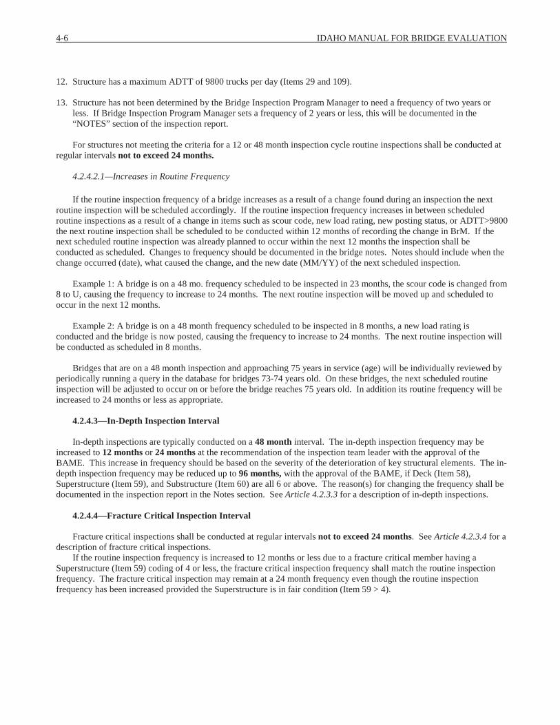
12. Structure has a maximum ADTT of 9800 trucks per day (Items 29 and 109).
13. Structure has not been determined by the Bridge Inspection Program Manager to need a frequency of two years or less. If Bridge Inspection Program Manager sets a frequency of 2 years or less, this will be documented in the “NOTES” section of the inspection report.
For structures not meeting the criteria for a 12 or 48 month inspection cycle routine inspections shall be conducted at regular intervals not to exceed 24 months.
4.2.4.2.1—Increases in Routine Frequency
If the routine inspection frequency of a bridge increases as a result of a change found during an inspection the next routine inspection will be scheduled accordingly. If the routine inspection frequency increases in between scheduled routine inspections as a result of a change in items such as scour code, new load rating, new posting status, or ADTT>9800 the next routine inspection shall be scheduled to be conducted within 12 months of recording the change in BrM. If the next scheduled routine inspection was already planned to occur within the next 12 months the inspection shall be conducted as scheduled. Changes to frequency should be documented in the bridge notes. Notes should include when the change occurred (date), what caused the change, and the new date (MM/YY) of the next scheduled inspection.
Example 1: A bridge is on a 48 mo. frequency scheduled to be inspected in 23 months, the scour code is changed from 8 to U, causing the frequency to increase to 24 months. The next routine inspection will be moved up and scheduled to occur in the next 12 months.
Example 2: A bridge is on a 48 month frequency scheduled to be inspected in 8 months, a new load rating is conducted and the bridge is now posted, causing the frequency to increase to 24 months. The next routine inspection will be conducted as scheduled in 8 months.
Bridges that are on a 48 month inspection and approaching 75 years in service (age) will be individually reviewed by periodically running a query in the database for bridges 73-74 years old. On these bridges, the next scheduled routine inspection will be adjusted to occur on or before the bridge reaches 75 years old. In addition its routine frequency will be increased to 24 months or less as appropriate.
4.2.4.3—In-Depth Inspection Interval
In-depth inspections are typically conducted on a 48 month interval. The in-depth inspection frequency may be increased to 12 months or 24 months at the recommendation of the inspection team leader with the approval of the BAME. This increase in frequency should be based on the severity of the deterioration of key structural elements. The in-depth inspection frequency may be reduced up to 96 months, with the approval of the BAME, if Deck (Item 58), Superstructure (Item 59), and Substructure (Item 60) are all 6 or above. The reason(s) for changing the frequency shall be documented in the inspection report in the Notes section. See Article 4.2.3.3 for a description of in-depth inspections.
4.2.4.4—Fracture Critical Inspection Interval
Fracture critical inspections shall be conducted at regular intervals not to exceed 24 months. See Article 4.2.3.4 for a description of fracture critical inspections.
If the routine inspection frequency is increased to 12 months or less due to a fracture critical member having a Superstructure (Item 59) coding of 4 or less, the fracture critical inspection frequency shall match the routine inspection frequency. The fracture critical inspection may remain at a 24 month frequency even though the routine inspection frequency has been increased provided the Superstructure is in fair condition (Item 59 > 4).
SECTION 4: INSPECTION 4-7
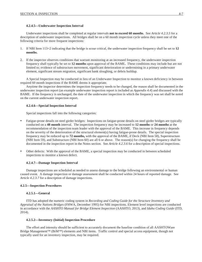
4.2.4.5—Underwater Inspection Interval
Underwater inspections shall be completed at regular intervals not to exceed 60 months. See Article 4.2.3.5 for a description of underwater inspections. All bridges shall be on a 60 month inspection cycle unless they meet one of the following criteria for more frequent inspections:
1. If NBI Item 113=2 indicating that the bridge is scour critical, the underwater inspection frequency shall be set to 12months.
2. If the inspector observes conditions that warrant monitoring at an increased frequency, the underwater inspection frequency shall typically be set to 12 months upon approval of the BAME. These conditions may include but are not limited to; evidence of substructure movement, significant deterioration or undermining in a primary underwater element, significant stream migration, significant bank sloughing, or debris buildup.
A Special Inspection may be conducted in lieu of an Underwater Inspection to monitor a known deficiency in between required 60 month inspections if the BAME deems it appropriate.
Anytime the inspector determines the inspection frequency needs to be changed, the reason shall be documented in the underwater inspection report (an example underwater inspection report is included as Appendix 4.4) and discussed with the BAME. If the frequency is unchanged, the date of the underwater inspection in which the frequency was set shall be noted on the current underwater inspection report.
4.2.4.6—Special Inspection Interval
Special inspections fall into the following categories:
Fatigue-prone details on steel girder bridges: Inspections on fatigue-prone details on steel girder bridges are typically conducted on a 48 month interval. The inspection frequency may be increased to 12 months or 24 months at the recommendation of the inspection team leader with the approval of the BAME. This increase in frequency depends on the severity of the deterioration of the structural element(s) having fatigue-prone details. The special inspection frequency may be reduced up to 72 months, with the approval of the BAME, if Deck (NBI Item 58), Superstructure (NBI Item 59), and Substructure (NBI Item 60) are all 6 or above. The reason(s) for changing the frequency shall be documented in the inspection report in the Notes section. See Article 4.2.3.6 for a description of special inspections.
Other defects: With the approval of the BAME, a special inspection may be conducted in between scheduled inspections to monitor a known defect.
4.2.4.7—Damage Inspection Interval
Damage inspections are scheduled as needed to assess damage to the bridge following an environmental or human caused event. A damage inspection or damage assessment shall be conducted within 24 hours of reported damage. See Article 4.2.3.7 for a description of damage inspections.
4.2.5—Inspection Procedures
4.2.5.1—General
ITD has adopted the numeric coding system in Recording and Coding Guide for the Structure Inventory and Appraisal of the Nations Bridges (FHWA, December 1995) for NBI inspections. Element level inspections are conductedin accordance with the AASHTO Manual for Bridge Element Inspection (AASHTO, 2013), and Idaho Coding Guide (ITD, 2014).
4.2.5.2—Inventory (Initial) Inspection Procedure
The effort and intensity should be sufficient to accurately document the baseline condition of all AASHTOWare Bridge Management™ (BrM™) elements and NBI items. Traffic control and special access equipment, though not typically used for an inventory inspection, may be required.

4-8 IDAHO MANUAL FOR BRIDGE EVALUATION
The inspection team should have a set of as-built bridge drawings (if available) to refer to when performing the inventory inspection. When bridge plans are not available, the inspection team shall take field measurements to complete the inventory inspection.
An example of a completed Structural Inventory and Appraisal report is included as Appendix 4.5. A blank Inventory Inspection form is included as Appendix 4.6
4.2.5.3—Routine Inspection Procedure
The inspection team shall provide all Structure Inventory and Appraisal (SI&A) data and other relevant element level data needed to determine the structural condition in sufficient detail to clearly establish the bridge’s condition and to ensure its continued safe operation.
The level of scrutiny and effort required to perform a routine inspection shall vary according to the structure’s type, size, design complexity, and existing conditions. To provide a reasonable level of confidence in the safety of the bridge, knowledge of the structure and good engineering judgment are necessary to determine those portions that shall receive close-up scrutiny during a routine inspection.
Routine inspections are generally conducted from the deck, ground, and/or water levels. Typically ladders are utilized and permanent work platforms or walkways may also be used, if present. Inspection of underwater members of the substructure is generally limited to observations during periods of low flow and/or probing/sounding for evidence of local scour.
If scour is occurring at foundations, in addition to documenting it with the scour defect, a detailed drawing of the scour as it relates to the foundation shall be provided as part of the inspection report. Detailed pictures should also beprovided for documented scour issues.
Photographs shall accompany the inspection reports showing:
bridge looking down roadway
elevation view of bridge
posting signs (if applicable)
any damage noted in the report
anything that warrants further review by the BAME
In general, the more severe the issue, the more detail and photographs should be provided in the inspection report. An example of a completed ITD Structure Inventory and Appraisal report is included in Appendix 4.5.
One channel cross section upstream of the bridge must be performed when the substructure or some portion of the substructure is in the water during routine inspections. Channel cross sections shall be performed at least every four years. If Item 113 = 2, a channel cross section shall be performed every two years. Certain circumstances, such as a flooding event or shift in stream flow, may require that channel cross sections be performed more frequently.
A channel cross section is not required when:
1. Channel cross sections are performed as part of an underwater inspection.
2. The structures SI&A item 113 is coded a ‘9’ for being on dry land.
3. Substructure is unseasonably wet but the substructure is typically dry at the time of inspection and all substructure elements can be inspected using surface techniques (e.g. visual, wading, probe, etc).
4. The bridge is a single span over a canal.
5. The structure has a constructed floor or full channel lining through it. This also includes pipes.
If the structure foundations are founded on rock and the probability of changes to the channel near the foundation are low then the frequency of the cross section may be extended to 10 years at the discretion of the BAME (this will be included in the channel notes). If not performing a channel cross section the inspector shall state the reason in the channel
SECTION 4: INSPECTION 4-9
notes of the inspection report. This shall give inspectors in the future the information they need to determine whether or not they are required to perform a channel cross section during the following inspection.
An example of a channel cross section is included in Appendix 4.1.
4.2.5.4—In-Depth Inspection Procedure
In-depth inspection reports shall generally contain sufficient detail to understand what elements were inspected at an in-depth level, description of findings (including sketches and photos as appropriate), and any other pertinent information to facilitate future inspections such as equipment and/or methods used to analyze and assess elements.
If an in-depth inspection is not done in association with a routine inspection and report it should be recorded on the non-SI&A inspection form. A blank non-SI&A inspection form is included as Appendix 4.7.
4.2.5.5—Fracture Critical Member Inspection Procedure
The inspection intensity of all FCM’s during a fracture critical inspection should be sufficient to discover the onset of fatigue cracking. The inspector must have a hands-on level of access to all FCMs. Prior to the inspection the inspector should review the available information for the bridge such as the construction plans, sketches, specifications, shop drawings, prior inspection reports, photos, etc. and consider the details present on the bridge along with the condition of the FCMs.
Inspection for each FCM shall adhere to the following general procedures.
1. Visually inspect for cracks, rust, nicks, gouges, or impact damage.
2. Check for loose, bent, misaligned, un-even or un-evenly loaded members.
3. Check all bolted, riveted, or welded connections in tension areas.
4. Use mirrors or other equipment to check inside surfaces.
5. Check all connections at gusset plates, with emphasis on the first row (closest row to edge of plate).
6. Check for any welds, including plug, tack, or repair welds.
7. Check the flanges of the steel girders in tension areas where they change thickness or widths.
In addition to the general procedures, each FC bridge shall have unique procedures specific to the bridge which contain information necessary to convey to an inspector preparing to perform an FC inspection. The unique procedures describe additional steps in the inspection plan and are intended to mitigate significant risk factors associated with a particular bridge.
The unique procedures summarize in the written narrative and where feasible by annotation on the drawings identifying FCMs, the pertinent details and/or focus (emphasis) areas for the bridge. It is not necessary to list each FCM in the narrative of the unique procedure, as other sections of the report contain this information. However, if one FCM is especially severe then specific mention of that FCM and its particular concern might warrant specific mention in the unique procedures.
Generally speaking unique procedures are brief and concise. On some bridges in very good condition with no known defects or risk factors, unique procedures may not be applicable beyond a reference to the general procedures. Note this accordingly on the form. In other instances, bridges in poor condition or bridges with several risk factors present will contain several steps in the unique procedures to convey this information to future inspectors.
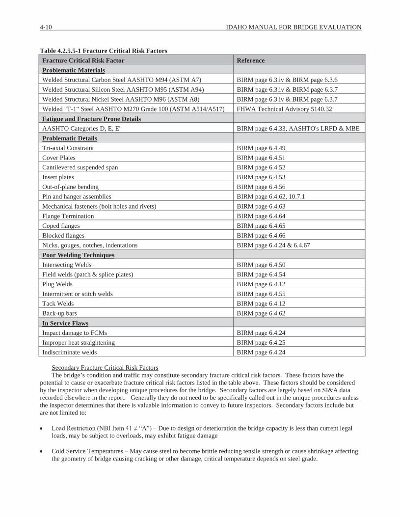
Potential risk factors for FCMs and their reference can be found in table 4.2.5.5-1; the table is not all inclusive but is to be used as a guide to assess risk and to develop specific/unique inspection procedures.
4-10 IDAHO MANUAL FOR BRIDGE EVALUATION
Table 4.2.5.5-1 Fracture Critical Risk FactorsFracture Critical Risk Factor ReferenceProblematic MaterialsWelded Structural Carbon Steel AASHTO M94 (ASTM A7) BIRM page 6.3.iv & BIRM page 6.3.6Welded Structural Silicon Steel AASHTO M95 (ASTM A94) BIRM page 6.3.iv & BIRM page 6.3.7Welded Structural Nickel Steel AASHTO M96 (ASTM A8) BIRM page 6.3.iv & BIRM page 6.3.7Welded "T-1" Steel AASHTO M270 Grade 100 (ASTM A514/A517) FHWA Technical Advisory 5140.32Fatigue and Fracture Prone DetailsAASHTO Categories D, E, E' BIRM page 6.4.33, AASHTO's LRFD & MBEProblematic DetailsTri-axial Constraint BIRM page 6.4.49Cover Plates BIRM page 6.4.51Cantilevered suspended span BIRM page 6.4.52Insert plates BIRM page 6.4.53Out-of-plane bending BIRM page 6.4.56Pin and hanger assemblies BIRM page 6.4.62, 10.7.1Mechanical fasteners (bolt holes and rivets) BIRM page 6.4.63Flange Termination BIRM page 6.4.64Coped flanges BIRM page 6.4.65Blocked flanges BIRM page 6.4.66Nicks, gouges, notches, indentations BIRM page 6.4.24 & 6.4.67Poor Welding TechniquesIntersecting Welds BIRM page 6.4.50Field welds (patch & splice plates) BIRM page 6.4.54Plug Welds BIRM page 6.4.12Intermittent or stitch welds BIRM page 6.4.55Tack Welds BIRM page 6.4.12Back-up bars BIRM page 6.4.62In Service FlawsImpact damage to FCMs BIRM page 6.4.24Improper heat straightening BIRM page 6.4.25Indiscriminate welds BIRM page 6.4.24
Secondary Fracture Critical Risk FactorsThe bridge’s condition and traffic may constitute secondary fracture critical risk factors. These factors have the
potential to cause or exacerbate fracture critical risk factors listed in the table above. These factors should be consideredby the inspector when developing unique procedures for the bridge. Secondary factors are largely based on SI&A data recorded elsewhere in the report. Generally they do not need to be specifically called out in the unique procedures unless the inspector determines that there is valuable information to convey to future inspectors. Secondary factors include but are not limited to:
– Due to design or deterioration the bridge capacity is less than current legal loads, may be subject to overloads, may exhibit fatigue damage
Cold Service Temperatures – May cause steel to become brittle reducing tensile strength or cause shrinkage affecting the geometry of bridge causing cracking or other damage, critical temperature depends on steel grade.

SECTION 4: INSPECTION 4-11
Poor Superstructure (NBI – Significant section loss in critical stress area. Minor fatigue or out of plane bending cracks may be present in major structural elements.
– Fatigue, fracture, and toughness were not primary concerns when designing bridges prior to the 1980’s. Material standards have become more stringent over time; there may be problematic materials or problematic details that should be noted on these older bridges.
Long Service Life (Years of service > 75) – In addition to material standards, these bridges have been subjected to more loading cycles increasing the likelihood of fatigue issues.
– Bridge is subject to more loading cycles and potentially more overweight traffic increasing the likelihood of fatigue issues.
Retrofits and repairs – Has the potential to introduce problematic details and poor welding techniques, may be an indication that the bridge has a history of structural problems.
EquipmentAt a minimum the inspector should have a dye penetrant kit and magnifying glass on-hand. Lighting to ensure details
are visible may also be necessary on some bridges. Equipment necessary to access FCM’s such as ladder, UBIT or climbing equipment should be listed on the FC report.
In some cases it may be appropriate for the inspector to recommend using additional NDT equipment such as magnetic particle, ultrasonic, eddy current, acoustic emission, and radiography to evaluate a detail, particularly if there are known defects or past history of problems with the detail on the bridge. Additional NDT equipment usually requires additional supporting resources such as a generator or personnel with expertise using this equipment. Additional NDT testing shall be at the discretion of the BAME.
The recommendation for additional NDT testing should be in the NOTES section of the routine inspection report. If additional NDT testing is necessary for future FC inspections in order to monitor an issue, the bridge’s unique procedures should describe where (what portion of the FCM) and at what frequency (how often) these defects are to be inspected with these additional tools. This is to inform future inspectors of the tools they will need to properly evaluate the FCMs on thebridge during future FC inspections.
Fracture Critical ReportAn annotated Fracture Critical Inspection Summary form can be found in Appendix 4.2, an example Fracture Critical
Inspection Report can be found in Appendix 4.3. At a minimum the FC report should include:
a schematic of the superstructure with all FCM’s and unique features (if feasible) identified
equipment required to properly access and assess FCMs (access equipment required is a dropdown menu on FC summary)
Sketches or annotated design plans showing FCM members to be visually monitored over time
A description and condition of each FCM inspected
Procedures necessary to inspect FCMs including:
a reference to the general procedures of article 4.2.5.5
any procedures to monitor risk factors listed in table 4.2.5.5-1
any hazards or other challenges to properly access FCMs
4-12 IDAHO MANUAL FOR BRIDGE EVALUATION
4.2.5.6—Underwater Inspection Procedure
Each underwater inspection has procedures that are unique to the bridge as part of the inspection report. Procedures should include:
a description of underwater elements to be inspected
scour countermeasures, if any, to be inspected
inspection methods, frequencies, other scheduling considerations
equipment needed for the inspection
access points
hydraulic features affecting the structure and/or inspection
risk factors
At the conclusion of every dive, the diver must go over the inspection findings with the team leader in order to verify that the notes taken by staff on the surface are a correct representation of what the diver found. The diver should also go over all underwater photos, making sure that the photo numbers and descriptions are correct.
One channel cross section upstream of the bridge shall be performed on each underwater inspection. An example of an underwater inspection report is included as Appendix 4.4. An example of a channel cross section is included in Appendix 4.1.
4.2.5.8—Damage Inspection Procedure
The scope of damage inspections varies widely depending on upon the extent of the damage, the volume of traffic encountered, the location of the damage on the structure, and documentation needs. At a minimum, photographs and measurements shall be taken to show the extent of damage.
The inspector shall obtain sufficient information for the BAME to accurately assess the condition of bridge and determine a course of action. Potential courses of action include but are not limited to:
placement of emergency load restrictions
partial or full closure of the bridge to traffic
repairs
For scour critical bridges, ITD utilizes a proprietary alert system BridgeWatch™. BridgeWatch™ takes rain, snow, and stream gauge data into account to determine when there is a potential for high flows. If it is determined that a high flow has occurred or is occurring at a scour critical bridge, a damage assessment (see Article 4.2.3.7.1) or inspection may be required to assess possible damage.
A damage inspection should be recorded on the non-SI&A inspection form. A blank non-SI&A inspection form is included as Appendix 4.7.
4.2.5.9—Critical Deficiency (Finding) Procedures
4.2.5.9.1 –Critical Finding Definition
A critical finding is any one or more of the following conditions:
1. A maintenance recommendation with an emergency priority assigned by the bridge inspector
SECTION 4: INSPECTION 4-13
2. Any of the following NBI items are a 2 or less:a) Item 58 (Deck)b) Item 59 (Superstructure)c) Item 60 (Substructure)1
3. Any of the following NBI items are a 3 or less:a) Item 61 (Channel and Channel Protection)b) Item 62 (Culverts)
4. Item 41 (Structure Status) = B
5. Any event causing immediate concern to the traveling public, e.g., a bridge hit, flood, earthquake, etc.
6. When a bridge has a significant structural problem that requires an emergency load restriction, lane closure, bridge closure, or if a bridge has failed.
4.2.5.9.2—Critical Finding Reporting
The Inspection Team Leader shall notify the bridge owner/district personnel of all critical findings immediately. Due to the urgent nature, notification may be initially done through a phone call, meeting, or an email. However, formal notification shall occur shortly thereafter by completing and sending a Local Agency Communication Verification (see Appendix 4.8 for blank form) to local bridge owners or a Critical Finding Communication (see Appendix 4.9 for blank form) to appropriate ITD personnel. The purpose of these forms is to provide added visibility and attention for bridge owners/district personnel so that they can quickly and diligently take actions to resolve. Typically the Local Agency Communication Verification will be shared and signed at the initial meeting with the bridge owner.
A complete list of highway officials is contained in the Directory of Idaho Government Officials published yearly by the Association of Idaho Cities, www.idahocities.org
In addition to completing these forms, the following information shall be documented in the Notes section of the inspection report:
1. a brief summary of the critical finding
2. contact information for the bridge owner representative (name, title, phone number, etc.)
3. date of conversation with bridge owner representative
4. brief summary of interim actions that were/are to be taken, e.g., bridge closure, lane restriction, load posting
5. assign a priority (2 days, 10 days, 30 days)
The inspector shall inform the bridge owner or district personnel that the Bridge Asset Management office must be notified when repairs are completed.
4.2.5.9.3– Emergency Notification to Police and Public
If the inspector determines that there is an immediate danger to the traveling public, state or local law enforcement and the BAME shall be contacted immediately. The bridge shall be closed. If the bridge is owned by the state, it shall be closed in accordance with the ITD Maintenance Manual, Article 322.03.
1 If Item 60 is a 2 because Item 113 (Scour Critical Bridges) = 2: An initial Critical Finding notification shall be made. Subsequent Critical Finding notifications shall be made every five years, rather than yearly. The bridge shall be monitored with BridgeWatch™, an online scour critical bridge monitoring system.

4-14 IDAHO MANUAL FOR BRIDGE EVALUATION
4.2.5.9.4 – Critical Finding Procedures for ITD Maintained Structures
When a critical finding(s) is discovered during the inspection of a state-owned structure, the following procedure shall be followed:
1. Notification: In addition to the immediate notification described in Article 4.2.5.9.2, a completed Critical Findings Communications form shall be sent to the District Engineer and Maintenance Engineer within 24 hours of discovery of the critical finding. Copy the BAME and the Database Manager when sending Critical Findings Notification Forms to the Districts.
2. Action: The District Engineer or designee shall be required to perform the necessary actions within the prescribed timeframes on the form. A representative from the District is required to notify the Database Manager when proper action has been taken. Once BAM is notified, the BrM™ database shall be updated to reflect the current bridge condition.
3. Follow Up: If BAM is not notified that necessary actions were taken within the required timeframes, the District shall be contacted again by either e-mail or phone. The bridge shall be added to the Critical Deficiency Tracking System and continue to be monitored. If after two attempts BAM is unable to obtain confirmation from the District Engineer or designee that the necessary actions were taken, then the BAME will escalate the matter to the Chief of Operations.
All correspondence between the District and the Bridge Asset Management office should be documented in the bridge file. The date and brief summary of repairs that were made, or are scheduled to be made, shall be documented if it is not detailed in the correspondence.
The BrM™ Database Manager shall forward copies of the critical findings inspection reports and local agency communication verifications to the Bridge Asset Management Engineer, the Bridge Design Engineer, and the FHWA Division Bridge Engineer monthly.
4.2.5.9.5 – Critical Finding Procedures for Locally Owned Structures
When a critical finding(s) is discovered during the inspection of a locally-owned structure, the following procedures shall be followed:
1. Notification: In addition to the immediate notification described in Article 4.8.1.4.2, a completed Local Agency Communication Verification form shall be sent to the local agency within 24 hours of discovery of the critical finding. Copy the BAME and the Database Manager when sending Critical Findings Notification Forms to local agencies.
2. Action: The local agency shall be required to perform the necessary actions within the prescribed timeframes on the form and contact the Database Manager when proper action has been taken. Once BAM is notified, the BrM™database shall be updated to reflect the current bridge condition.
3. Follow Up: If the local agency fails to notify BAM within the timeframes identified above, a follow-up letter shall be sent by the BAM Engineer. At this point the bridge shall be added to the Critical Deficiency Tracking System. If the local agency fails to notify BAM within 5 business days that corrective action has been taken, a second follow-up letter shall be sent by the Chief Engineer or designee. This letter shall inform the local agency that Federal and State funds may be suspended until appropriate corrective actions are taken. The FHWA Division Administrator and LHTAC shall be copied on the letter in addition to appropriate ITD personnel. Additionally, the appropriate ITD District Engineer shall be contacted and either he/she or designee shall follow-up with local highway agency personnel and offer assistance to get proper action taken.
4.2.5.9.6 – Critical Findings Tracking System
ITD shall maintain a system that tracks all critical findings. When a critical finding has been resolved, the tracking system shall be updated to indicate the critical finding has been closed. A historical record of resolved critical findings shall be maintained in order to track the types of critical findings found and to identify other bridges which may have similar structural details. At the discretion of the Program Manager, inspection of other bridges with similar structural details may be scheduled to verify that the critical finding is isolated to the identified bridge(s).

SECTION 4: INSPECTION 4-15
4.2.5.10—Procedure for Scour Evaluation of Bridges Recently Added to the Inventory
As part of federal requirements, all new bridges designed and constructed with federal funds must be assessed for their scour vulnerability during the design phase according to HEC 18 and therefore are assumed to be low risk for failure due to scour, i.e. Item 113 = 8 unless inspection findings show otherwise. For new non-federal aid bridges and existing bridges recently added to Idaho’s inventory the following process will occur:
At least once every two months, the Special Projects Engineer will obtain a report from the bridge inspection database of all bridges that haven’t been evaluated for scour, i.e. Item 113 = 6.
This set of bridges will be screened according to the flow chart located in Appendix 4.10 and a new code for Item 113 may be assigned.
If the Scour Committee is unable to properly assess the bridge, it will be assigned to a consultant engineer for a complete scour evaluation.
Assessments that can be done by the Scour Committee will be completed within 90 days of the database inquiry. In an effort to control costs and understanding that site visits to a bridge are best performed at certain times of the year, ITD anticipates that a consultant evaluation can take up to one year after the initial screening by the Scour Committee. Bridgesthat are being evaluated for scour by a consultant will be considered scour critical and added to the BridgeWatch™ system until the evaluation is completed.
4.2.5.11—Unknown Foundations Procedure
ITD utilizes all its resources, e.g., plan archives, inspection files, design files, and local highway district contacts to locate plans for each bridge in the inventory. However in some cases, primarily with local bridges, plans cannot be located. Without foundation drawings, appropriate calculations for scour evaluations cannot be made. Item 113 (Scour Critical Bridges) is coded a U for bridges with unknown foundations. This coding is primarily used when it cannot be determined if a bridge’s foundations are spread footings or piles. If the foundation type can be determined by routine or underwater inspection, Item 113 shall be changed to the appropriate code.
ITD has developed a flow chart (see Appendix 4.11), based on a select number of NBI items, to determine whether an unknown foundation bridge is at high or low risk for failure during a flooding event. A bridge is categorized as low risk if it has performed well, has a low ADT, short detour length and has no history of significant scour related problems. High risk infers that the bridge has performed satisfactorily, but because of ITD defined criteria and experiences, a higher level of scrutiny is needed.
The risk category for an unknown foundation bridge is based on the following NBI items:
Item 71 - Waterway Adequacy
Item 61 - Channel and Channel Protection
Item 45 - Number of Main Spans
Item 46 - Number of Approach Spans
Item 19 - Detour Length
Item 29 – ADT
Failure risk for unknown foundation bridges with four or more spans shall be determined by the scour committee on a case-by-case basis since potential risk factors for multi-spans may not be adequately represented in the above NBI items.
A plan-of-action (POA) shall be developed for all unknown foundation bridges. BrM™ is the Department’s filing location (electronic only) for scour POA’s. Each POA shall be electronically linked to the bridge record in BrM™. All other scour related documents (if applicable) shall be retained in the bridge file.

4-16 IDAHO MANUAL FOR BRIDGE EVALUATION
High RiskA bridge shall be categorized as high risk if it meets one of the following criteria:
1. The bank and/or protection is undermined or if overtopping of the bridge deck is possible (Waterway Adequacy or Channel Protection < 5).
2. The bridge has 2 or 3 spans, bank and/or protection is beginning to slump or erode, and overtopping is a slight possibility (Waterway Adequacy and Channel Protection < 7).
3. The bridge has one span, bank and/or protection is beginning to slump or erode, overtopping is a slight possibility, ADT is greater than 100, and the detour length is greater than 10 miles (Waterway Adequacy and Channel Protection < 7 and Detour Length > 10 and ADT > 100).
4. The Scour Committee has determined that exhibited scour warrants High Risk monitoring. Undermining is minimal and foundation type is unable to be determined.
High risk unknown foundation bridges shall be monitored on the BridgeWatch™ system in addition to their routine and/or underwater inspections at frequencies specified in Article 4.2.4.2 – Routine Inspection Interval and Article 4.2.4.5– Underwater Inspection Interval
A high risk POA is similar to those for bridges determined to be scour critical. At a minimum, each high risk bridge is monitored in BridgeWatch™. BridgeWatch™ utilizes real-time data to continuously monitor bridge sites for local conditions that may increase the likelihood of a scour event occurring (high stream flow, heavy rainfall, etc.).
In addition to BridgeWatch™, additional monitoring occurs during routine and underwater (if applicable) inspections and after major flood events. The bridge inspector shall review high risk bridge POAs with the bridge owner(s) at least once every five years or more frequently if significant scour is observed by the inspector. Inspectors shall review and consider the POA as they perform bridge inspections.
Based on information in bridge inspection reports and feedback from bridge inspectors and bridge owners/maintenance personnel, the Scour Committee may make recommendations to the bridge owner for:
foundation investigation
countermeasure installation
programming for bridge replacement (usually if significant scour occurs or recurs frequently)
Low RiskLow risk unknown foundation bridges shall be monitored by routine and/or underwater inspections at frequencies
specified in Article 4.2.4.2 – Routine Inspection Interval and Article 4.2.4.5 – Underwater Inspection Interval.The POA for a low risk bridge shall describe an ongoing monitoring plan. Monitoring typically occurs during routine
biennial inspections and after major flood events. The POA shall be sent to the bridge owner once every five years. Inspectors shall review and consider the POA as they perform bridge inspections. Inspectors may make a recommendation to the Scour Committee to re-assign a low risk bridge to high risk if field conditions warrant. The inspection report shall document findings and other pertinent information that the Scour Committee should consider for reassignment.
Additional Information:
FHWA memo 1/9/2008: Technical Guidance for bridges over waterways with unknown foundations
FHWA memo 6/3/2009: FAQs - Bridges over waterways with unknown foundations
FHWA memo 10/29/2009: Additional Guidance for assessment of bridges over waterways with unknown foundations
SECTION 4: INSPECTION 4-17
4.2.5.12 – Procedure for Scour Critical or High Risk Unknown Foundation Bridges Over Canals
Bridges over irrigation canals that have been determined to be scour critical or a high risk unknown foundation shall not be placed on BridgeWatch. Inspection frequency and Plan of Actions will be the same as other scour critical or high risk unknown foundation bridges. BridgeWatch utilizes the bridges drainage basin to determine if an over-threshold rainfall or snowmelt event is occurring. Canals have no natural drainage basin so an alert will never occur.
4.3—NONREGULATORY INSPECTION PRACTICES
4.3.6—Complex Bridge Inspections
Complex bridge inspections are required on bridges that include details such as moving parts, cable suspension, oreyebar-chain suspension systems. These complex details require individual inspection procedures that are not typically inspected with sufficient scrutiny in the routine inspection. The complex bridges in Idaho and their inspection procedures are included in below. Complex bridge inspections shall be on the same inspection frequency as routine inspections.
The Code of Federal Regulations [CFR 650.313(f)] requires state agencies to “Identify specialized inspection procedures and additional inspector training and experience required to inspect complex bridges according to those procedures.” Inspectors should review the inspection procedures specific to a complex bridge prior to completing an inspection on these bridges. ITD does not maintain a special staff for inspection of complex bridges. The procedures for all complex bridges inspected by ITD are linked in BrM™.
4.3.6.1—Movable Bridges
Idaho has the following lift bridge:
Snake River (Br. Key 10360), US 12, in Lewiston at State Line
This is a border bridge shared with Washington. Washington Department of Transportation is responsible for the development of inspection procedures and inspection of this bridge.
4.3.6.2—Suspension Bridges
Cable suspended structures contain fracture critical members and fatigue-prone details, and the inspection of those components are specifically covered in those types of inspections. The intent of the inspection of these complex details is to identify the structural geometry and the different load paths in order to assure that the structure is functioning as originally designed. The two distinct load paths consist of the cable suspension system back to the cable anchorages,along the stiffener truss, and down the interior piers. Over time, the cable suspension system shall relax or the interior bents can settle, transferring more of the load into these components. This inspection shall assess whether that load transfer is still within tolerable limits.
Idaho has the following suspension bridge:
Dent Bridge (Br. Key 20295), N. Fork Clearwater River, STC 4783, 8.8 N. 3.7 E. Orofino
4.3.6.3—Cable-Stayed Bridges
Idaho does not have any publicly owned cable-stayed vehicular bridges.
4.3.6.4—Tied Arch Bridges
ITD does not consider these bridge types to be complex. Follow routine and applicable fracture critical inspection procedures.
4-18 IDAHO MANUAL FOR BRIDGE EVALUATION
4.3.6.5—Prestressed Concrete Segmental Bridges
ITD does not consider these bridge types to be complex. Follow routine inspection procedures.
4.4—REFERENCES
Code of Federal Regulations
AASHTO Manual for Bridge Evaluation Second Edition, 2014
FHWA manual “Inspection of Fracture Critical Bridge Members” (FHWA-IP-86-26)
The ‘‘Recording and Coding Guide for Structure Inventory and Appraisal of the Nation’s Bridges,’’
December 1995, Report No. FHWA–PD–96–001, http//www.fhwa.dot.gov//bridge/mtguide.doc
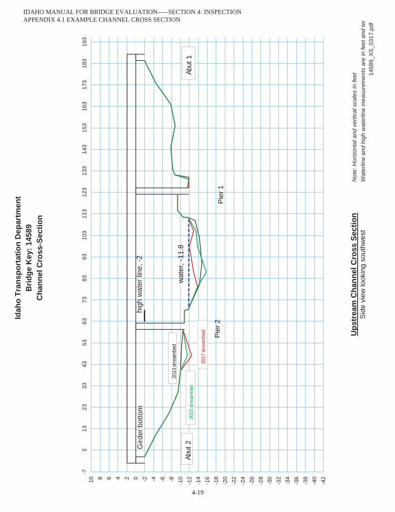
Idah
o Tr
ansp
orta
tion
Dep
artm
ent
Brid
ge K
ey: 1
4589
Cha
nnel
Cro
ss-S
ectio
n
Ups
trea
m C
hann
el C
ross
Sec
tion
Not
e: H
oriz
onta
l and
ver
tical
sca
les
in fe
etS
ide
view
look
ing
sout
hwes
tW
ater
line
and
high
wat
erlin
e m
easu
rem
ents
are
in fe
et a
nd te
n14
589_
XS_0
317.
3/2/
2017
Jim
Hol
land
wat
er, -
11.8
high
wat
er li
ne, -
2G
irder
bot
tom
Pier
2Pi
er 1
-42
-40
-38
-36
-34
-32
-30
-28
-26
-24
-22
-20
-18
-16
-14
-12
-10-8-6-4-20246810
-73
1323
3343
5363
7383
9310
311
312
313
314
315
316
317
318
319
3
Abut
1
Abut
2
2013
stre
ambe
d
2015
stre
ambe
d
2017
stre
ambe
d
IDAHO MANUAL FOR BRIDGE EVALUATION-----SECTION 4: INSPECTION APPENDIX 4.1 EXAMPLE CHANNEL CROSS SECTION
4-19
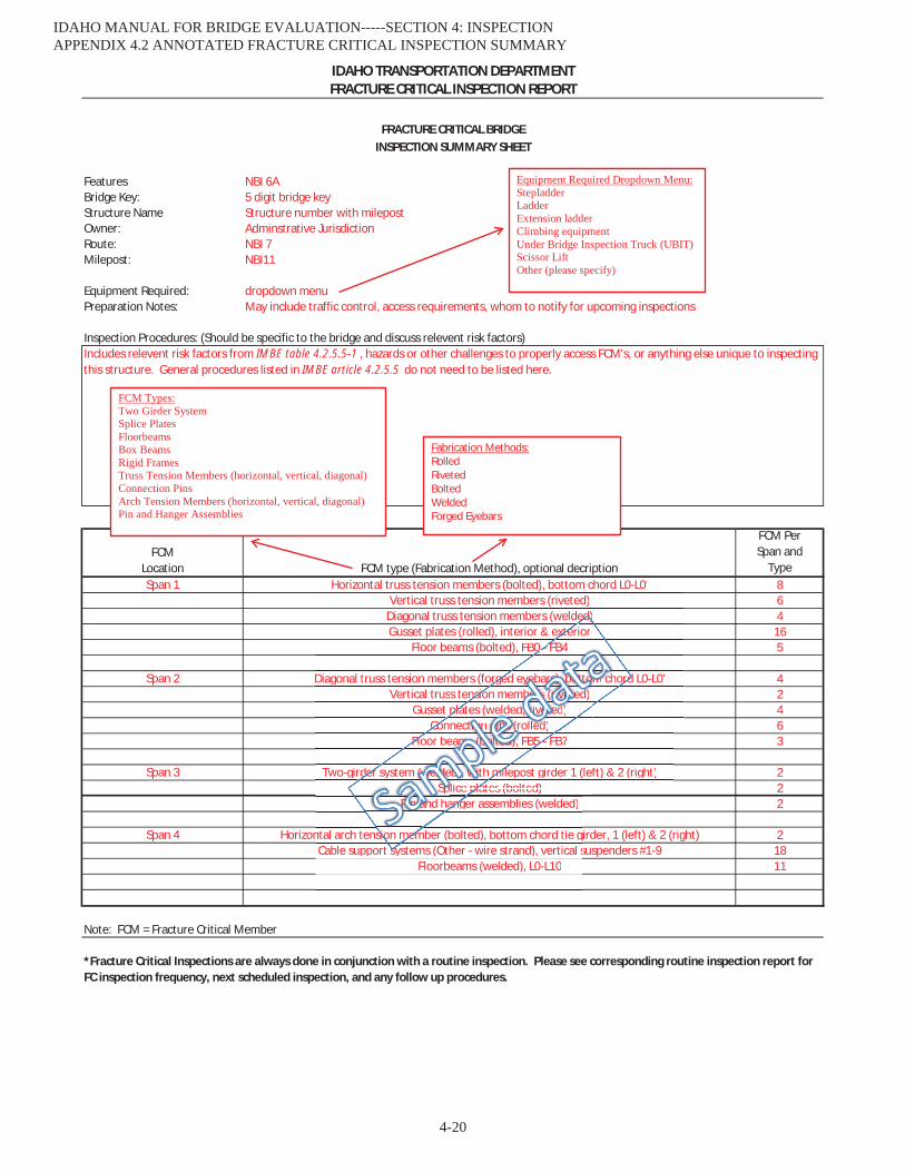
Features NBI 6ABridge Key: 5 digit bridge keyStructure Name Structure number with milepostOwner: Adminstrative JurisdictionRoute: NBI 7Milepost: NBI11
Equipment Required: dropdown menuPreparation Notes: May include traffic control, access requirements, whom to notify for upcoming inspections
Inspection Procedures: (Should be specific to the bridge and discuss relevent risk factors)
FCM Per Span and
Type864
165
42463
222
21811
Note: FCM = Fracture Critical Member
Span 2
Span 3
FRACTURE CRITICAL BRIDGEINSPECTION SUMMARY SHEET
FRACTURE CRITICAL INSPECTION REPORTIDAHO TRANSPORTATION DEPARTMENT
FCM Location
Includes relevent risk factors from IMBE table 4.2.5.5-1 , hazards or other challenges to properly access FCM's, or anything else unique to inspecting this structure. General procedures listed in IMBE article 4.2.5.5 do not need to be listed here.
FCM type (Fabrication Method), optional decription
*Fracture Critical Inspections are always done in conjunction with a routine inspection. Please see corresponding routine inspection report for FC inspection frequency, next scheduled inspection, and any follow up procedures.
Span 4
Span 1 Horizontal truss tension members (bolted), bottom chord L0-L0'Vertical truss tension members (riveted)
Diagonal truss tension members (welded)
Splice plates (bolted)
Vertical truss tension members (riveted)Gusset plates (welded, riveted)
Gusset plates (rolled), interior & exteriorFloor beams (bolted), FB0 - FB4
Two-girder system (welded), with milepost girder 1 (left) & 2 (right)
Diagonal truss tension members (forged eyebars), bottom chord L0-L0'
Connection pins (rolled)
Cable support systems (Other - wire strand), vertical suspenders #1-9
Floor beams (bolted), FB5 - FB7
Floorbeams (welded), L0-L10
Horizontal arch tension member (bolted), bottom chord tie girder, 1 (left) & 2 (right)
Pin and hanger assemblies (welded)
Vertical trusGusset
Two-girder
Diagonal truss tension mem
Co
Cable support systems (Other - wire strand), vertical s
Fl
Floorbeams (welded), L0-L10
ntal arch tension member (bolted), bottom chord tie g
anger assemblies (welded)SpSpSpSpppppppppp
der system (w(w(w(w(w(w(w(w(w(w(w(wwwwww(w(w(w(w(w(w(wwww(www(ww(w(ww(ww(w(w(wwweleleleleleleleleleleleleeleleleleeeleleleeleleleleleleleleleelllldddddddeddedededededdddddddddddddddddddddddddddd
ConFloor be
sion mem
PPPPPPiPiPiPiPiiPiPiPPPiPiPiPiPiPPiPPiiPiPiPiPiPPiPiPPiiPiPP nnnnnnnnnnnnnnnnnnnnnnnnnnnnnnnnnnnnn aaaaaaaanananananananaaaaananaaaaananaaaaanaaaa d hang
eam
plates (bolted)llice p
pla
eed)d)d)d)d)d)d)d)d)d)d)d)d)d)d)d)d)d)d)d)d)d)d)d)d)d)d)dd)d)d)d)d)d)d)d))d
neeammmmmm
s tpla
mbe
ft) & 2 (right)
members (bolted)tension memberstension member(rolled), interior &
(b lt d) FB0
(lef
ms (bolted), FB0
lates (bolted)milepost girder 1 (
5 - FB7
ce pla
nsion membebebebebebebebebebebebebeebeebebebebebebebebebebebebeeebeebebeebeersrsrsrsrsrsrsrsrsssssrsrsrsrssrsrssssrssrsrsrsrsrsates (welded,,,,,,,,, rrrrrrrrrrrrrrrrrrrrrrrrrrrrrrrriviviviviviviviiviviviivi eeeeeeeeeeee
))))))))))))))))))),,,,,,,,,,,,,,, wiwwiwiwiwwwwwwwiwiwiwiwiwiwiwiwiwwwiwiwiwiwiwiwwwiwiwiwwiwiwwiww thtt mi
rged eyeyeyeyeyeyeyeeyeyeyeeeeeeeeeeeeeeeeeey bab
ectitititititiiiiiiiiiiiiitiiitiitiiiioooooooononononononooooonoononononoooooonoononnooonoooo ppppppppppppppppppppppppppppppppppinininnnininininnnininininininininininininininininininininininnns sssssssssss s sss ss ssssssss sss s s ss ssss (r(r(r(r(r(r(((((( ollel dddddd)mmmmmmmmmmmmmmmmmmmmmmmmmmmmmmmmmmmmmmssssssssssssssssssssssssssss (b(b(b(b(b(b(b(b(b(b(b(b(b(b(b(b(b(b(b(b(b(bbb(bb(b(b(b(b(bbb(bbb(bb(b( oloololololololololololooololololoolooooooooooooooo teteteteteteeteteteteteteteteteteteteteteteteteteteteteeteteeteteteeeteteeteeeed)d)d)d)d)d)d)d)dd)d)d)d)d)d)d)d)d)d)d)d)d)d)d)d)d)d)d)d)d)d)d)d))ddddd , FB5 -
tensio
( ),
ers (forge
bottom chord L0-L0', bottom chord L0 L0s (riveted)s (welded)& exte
F
rd L0-L0'
ed)xterior
FB4
mmmmmmmmmmmmmmmmmmmmmmmmmmmmmmmmmmmmm cchorddd)
- FB4
totototototototoooototootoooototootoototoototootototooo
-
sssssssssssssssssssssssssssssssss ((((((((rrrrrriririririririrriririririririririririrrrriririririrrririveveveveveveveveveveveveeveeeeeeveveveveveeeeeeeeeeeeeeveetttttttttetetetetettttttttttttttttttettttt detetetetetetetetetetetetetetetetetetetetetetetettetetteteteteteteeteetetetedededededededededeeeeeeeeeee )))
aarsrsrsrsrsrsrsrsrsrssrssrsrsrsrsrsrsrsrrssrsrsssrsrsrsssrsrsrrsr ),),),),),),),),),),),),),),),),),),)),),),)),),),),),,),),),),)),,),),, bbbbbbbbbbbbbbbbbbbotototototototototototototototototototototototototototootototototototootooottttttttt
dd)
Equipment Required Dropdown Menu:StepladderLadderExtension ladderClimbing equipmentUnder Bridge Inspection Truck (UBIT)Scissor LiftOther (please specify)
FCM Types:Two Girder SystemSplice PlatesFloorbeamsBox BeamsRigid FramesTruss Tension Members (horizontal, vertical, diagonal)Connection PinsArch Tension Members (horizontal, vertical, diagonal)Pin and Hanger Assemblies
Fabrication Methods: Rolled Riveted Bolted Welded Forged Eyebars
IDAHO MANUAL FOR BRIDGE EVALUATION-----SECTION 4: INSPECTION APPENDIX 4.2 ANNOTATED FRACTURE CRITICAL INSPECTION SUMMARY
4-20

Features Payette River Inspection Date: xx/xx/xxxxBridge Key: 26680 Drawing #: 17195Structure Name X993080 100.32Owner: Boise CountyRoute: Boise StreetMilepost: 100.320
Equipment Required:Preperation notes:
Inspection Procedures:123
45678
FCM Per Girder or Truss Line
10124
1310124
13
Note: FCM = Fracture Critical Member
Floorbeams (rolled)Connection Pins (rolled)
Span 2Span 2
Climbing equipment needed to access floor beams
Span 2Span 2
Floorbeams (rolled)Span 1
Horizontal Truss Tension Members (forged eyebar), L0 - L7Diagonal Truss Tension Members (forged eyebar)
IDAHO TRANSPORTATION DEPARTMENT
Check spacers on pin assemblies to ensure members are being held in their proper positions.
Span 1
Bridge is >100 yrs old with unknown design load, unknown history of vehicle loading, unknown steel alloys in tension members.Emphasis on the eyebars - particularly the forged area around the eyebar head and shank looking for cracks.
FCMLocation
Connection Pins (rolled)
Diagonal Truss Tension Members (forged eyebar)Span 1Span 1
FCM Type
Check the misaligned eyebars for evidence of substructure movement, impact damage, and/or unitended force reversal.Emphasis on the misaligned eyebars as they may cause uneven and excessive loading on adjacent members.Check pins for signs of wear and corrosion. Recommend UT on a sample of pins periodically to check for internal flaws.
Horizontal Truss Tension Members (forged eyebar), L0 - L7
FRACTURE CRITICAL BRIDGEINSPECTION SUMMARY SHEET
FRACTURE CRITICAL INSPECTION REPORT
Emphasis on the misaligned pin. This is creating a single shear (double the intended load) concentration on the pin.
*Fracture Critical Inspections are always done in conjunction with a routine inspection. Please see corresponding routine inspection report for FCinspection frequency, next scheduled inspection, and any follow up procedures.
Climbing gear, ladder, scaffold
Inspect according to General procedures in IMBE 4.2.5.5.
IDAHO MANUAL FOR BRIDGE EVALUATION-----SECTION 4: INSPECTIONAPPENDIX 4.3 EXAMPLE FRACTURE CRITICAL INSPECTION REPORT
4-21
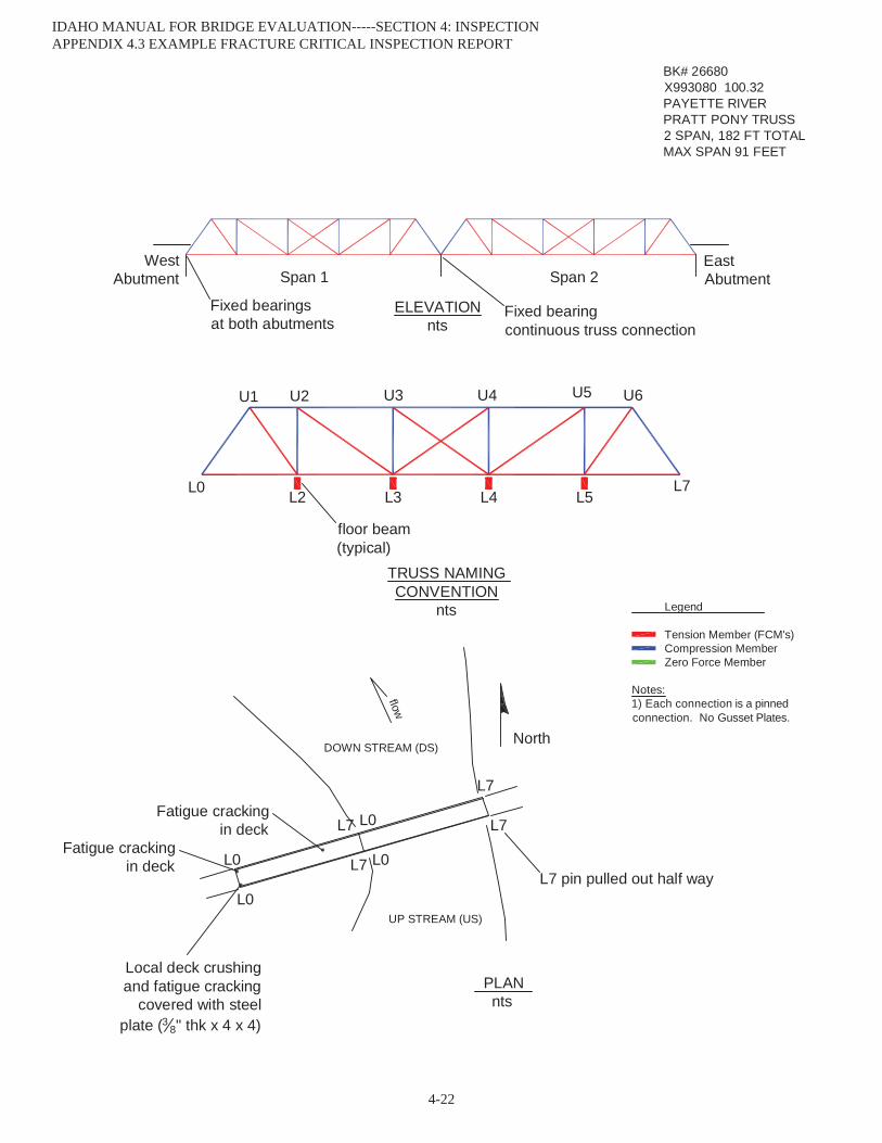
UP STREAM (US)
DOWN STREAM (DS)North
BK# 26680X993080 100.32PAYETTE RIVERPRATT PONY TRUSS2 SPAN, 182 FT TOTALMAX SPAN 91 FEET
PLAN nts
flow
W 880-9111 - F 463-75801117 So Camas - Nampa, ID
Hughes Engineering, P.C.
floor beam(typical)
L0
U1 U2 U3 U4 U6
ELEVATIONnts
Legend
Tension Member (FCM's)Compression MemberZero Force Member
Notes:1) Each connection is a pinned connection. No Gusset Plates.
TRUSS NAMING CONVENTION
nts
WestAbutment
EastAbutmentSpan 1 Span 2
26680_FC_0815.pdf
L2L7
U5
L0
L0L7
L7
L0
L0L7
L7
L3 L4 L5
Local deck crushing and fatigue cracking
covered with steel plate (3 8" thk x 4 x 4)
L7 pin pulled out half way
Fixed bearingcontinuous truss connection
Fixed bearingsat both abutments
Fatigue crackingin deck
Fatigue crackingin deck
IDAHO MANUAL FOR BRIDGE EVALUATION-----SECTION 4: INSPECTION APPENDIX 4.3 EXAMPLE FRACTURE CRITICAL INSPECTION REPORT
4-22

Feat
ures
:Pa
yett
e Ri
ver
FC In
spec
tion
Date
8/20
/201
5Br
idge
Key
:26
680
Hour
s1.
5St
ruct
ure
Nam
e:X9
9308
0 1
00.3
2O
wne
r:Bo
ise C
ount
yIn
spec
tor:
Davi
d Hu
ghes
Rout
e:Bo
ise S
tree
tCo
-Insp
ecto
r:M
ilepo
st:
100.
320
Trus
s/ G
irder
Span
Loca
tion
FCM
Insp
ecte
dDe
tail
Desc
riptio
nIn
spec
tion
Met
hod
Surf
ace
Prep
arat
ion
Rem
arks
Sout
h - U
S1
L0 -
L2Bo
ttom
Cho
rdDo
uble
bar
, for
ged
ends
VN
O
Sout
h - U
S1
L2 -
L3Bo
ttom
Cho
rdDo
uble
bar
, for
ged
ends
VN
O
Sout
h - U
S1
L3 -
L4Bo
ttom
Cho
rdDo
uble
bar
, for
ged
ends
VN
O
Sout
h - U
S1
L4 -
L5Bo
ttom
Cho
rdDo
uble
bar
, for
ged
ends
VN
O
Sout
h - U
S1
L5 -
L7Bo
ttom
Cho
rdDo
uble
bar
, for
ged
ends
VN
O
Sout
h - U
S1
L2 -
U1
Diag
onal
Doub
le b
ar, f
orge
d en
dsV
NO
Sout
h - U
S1
L3 -
U2
Diag
onal
Doub
le b
ar, f
orge
d en
dsV
NO
Sout
h - U
S1
L3 -
U4
Diag
onal
Sing
le b
ar, f
orge
d en
ds w
/ tur
n bu
ckle
VN
O
Sout
h - U
S1
L4 -
U3
Diag
onal
Sing
le b
ar, f
orge
d en
ds w
/ tur
n bu
ckle
VN
O
Sout
h - U
S1
L4 -
U5
Diag
onal
Doub
le b
ar, f
orge
d en
dsV
NO
Sout
h - U
S1
L5 -
U6
Diag
onal
Doub
le b
ar, f
orge
d en
dsV
NO
Sout
h - U
S1
L6 -
U7
Diag
onal
Doub
le b
ar, f
orge
d en
dsV
NO
Sout
h - U
S1
L0Pi
nV
NO
Sout
h - U
S1
L2Pi
nV
NO
Sout
h - U
S1
L3Pi
nV
NO
Sout
h - U
S1
L4Pi
nV
NO
Sout
h - U
S1
L5Pi
nV
NO
Sout
h - U
S1
L7Pi
nV
NO
Heav
y ru
stin
g an
d pi
ttin
g
Heav
y ru
stin
g an
d pi
ttin
g
Heav
y ru
stin
g an
d pi
ttin
g
Heav
y ru
stin
g, m
oder
ate
pitt
ing.
Slig
htly
ben
t
Heav
y ru
stin
g, m
oder
ate
pitt
ing
Heav
y ru
stin
g, m
oder
ate
pitt
ing
Heav
y ru
stin
g an
d pi
ttin
g
Heav
y ru
stin
g an
d pi
ttin
g
Heav
y ru
stin
g an
d pi
ttin
g
Heav
y ru
stin
g, m
oder
ate
pitt
ing
Heav
y ru
stin
g, m
oder
ate
pitt
ing
Heav
y ru
stin
g, m
oder
ate
pitt
ing
Heav
y ru
stin
g, m
oder
ate
pitt
ing.
Ext
erio
r bar
ben
t app
roxi
mat
ely
1"
Heav
y ru
stin
g, m
oder
ate
pitt
ing
Heav
y ru
stin
g, m
oder
ate
pitt
ing
FRAC
TURE
CRI
TICA
L IN
SPEC
TIO
N R
EPO
RTID
AHO
TRA
NSP
ORT
ATIO
N D
EPAR
TMEN
T
Heav
y ru
stin
g, m
oder
ate
pitt
ing
Heav
y ru
stin
g, m
oder
ate
pitt
ing
Heav
y ru
stin
g, m
oder
ate
pitt
ing
2668
0 FC
Rep
ort 0
815.
xls
Page
1 o
f 6
IDAHO MANUAL FOR BRIDGE EVALUATION-----SECTION 4: INSPECTION APPENDIX 4.3 EXAMPLE FRACTURE CRITICAL INSPECTION REPORT
4-23
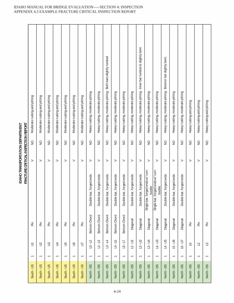
FRAC
TURE
CRI
TICA
L IN
SPEC
TIO
N R
EPO
RTID
AHO
TRA
NSP
ORT
ATIO
N D
EPAR
TMEN
T
Sout
h - U
S1
U1Pi
nV
NO
Sout
h - U
S1
U2Pi
nV
NO
Sout
h - U
S1
U3Pi
nV
NO
Sout
h - U
S1
U4Pi
nV
NO
Sout
h - U
S1
U5Pi
nV
NO
Sout
h - U
S1
U6Pi
nV
NO
Sout
h - U
S1
U7Pi
nV
NO
Nor
th -
DS1
L0 -
L2Bo
ttom
Cho
rdDo
uble
bar
, for
ged
ends
VN
O
Nor
th -
DS1
L2 -
L3Bo
ttom
Cho
rdDo
uble
bar
, for
ged
ends
VN
O
Nor
th -
DS1
L3 -
L4Bo
ttom
Cho
rdDo
uble
bar
, for
ged
ends
VN
O
Nor
th -
DS1
L4 -
L5Bo
ttom
Cho
rdDo
uble
bar
, for
ged
ends
VN
O
Nor
th -
DS1
L5 -
L7Bo
ttom
Cho
rdDo
uble
bar
, for
ged
ends
VN
O
Nor
th -
DS1
L2 -
U1
Diag
onal
Doub
le b
ar, f
orge
d en
dsV
NO
Nor
th -
DS1
L3 -
U2
Diag
onal
Doub
le b
ar, f
orge
d en
dsV
NO
Nor
th -
DS1
L3 -
U4
Diag
onal
Sing
le b
ar, f
orge
d en
ds w
/ tur
n bu
ckle
VN
O
Nor
th -
DS1
L4 -
U3
Diag
onal
Sing
le b
ar, f
orge
d en
ds w
/ tur
n bu
ckle
VN
O
Nor
th -
DS1
L4 -
U5
Diag
onal
Doub
le b
ar, f
orge
d en
dsV
NO
Nor
th -
DS1
L5 -
U6
Diag
onal
Doub
le b
ar, f
orge
d en
dsV
NO
Nor
th -
DS1
L6 -
U7
Diag
onal
Doub
le b
ar, f
orge
d en
dsV
NO
Nor
th -
DS1
L0Pi
nV
NO
Nor
th -
DS1
L2Pi
nV
NO
Nor
th -
DS1
L3Pi
nV
NO
Heav
y ru
stin
g, m
oder
ate
pitt
ing.
Ext
erio
r bar
slig
htly
ben
t.
Heav
y ru
stin
g, m
oder
ate
pitt
ing
Heav
y ru
stin
g, m
oder
ate
pitt
ing
Heav
y ru
stin
g an
d pi
ttin
g
Heav
y ru
stin
g an
d pi
ttin
g
Heav
y ru
stin
g an
d pi
ttin
g
Heav
y ru
stin
g, m
oder
ate
pitt
ing
Heav
y ru
stin
g, m
oder
ate
pitt
ing
Heav
y ru
stin
g, m
oder
ate
pitt
ing
Heav
y ru
stin
g, m
oder
ate
pitt
ing.
Inn
er b
ar tw
isted
& sl
ight
ly b
ent
Heav
y ru
stin
g, m
oder
ate
pitt
ing
Heav
y ru
stin
g, m
oder
ate
pitt
ing
Heav
y ru
stin
g, m
oder
ate
pitt
ing.
Bot
h ba
rs sl
ight
ly tw
isted
Mod
erat
e ru
stin
g an
d pi
ttin
g
Mod
erat
e ru
stin
g an
d pi
ttin
g
Mod
erat
e ru
stin
g an
d pi
ttin
g
Mod
erat
e ru
stin
g an
d pi
ttin
g
Heav
y ru
stin
g, m
oder
ate
pitt
ing
Heav
y ru
stin
g, m
oder
ate
pitt
ing
Mod
erat
e ru
stin
g an
d pi
ttin
g
Mod
erat
e ru
stin
g an
d pi
ttin
g
Mod
erat
e ru
stin
g an
d pi
ttin
g
2668
0 FC
Rep
ort 0
815.
xls
Page
2 o
f 6
IDAHO MANUAL FOR BRIDGE EVALUATION-----SECTION 4: INSPECTION APPENDIX 4.3 EXAMPLE FRACTURE CRITICAL INSPECTION REPORT
4-24
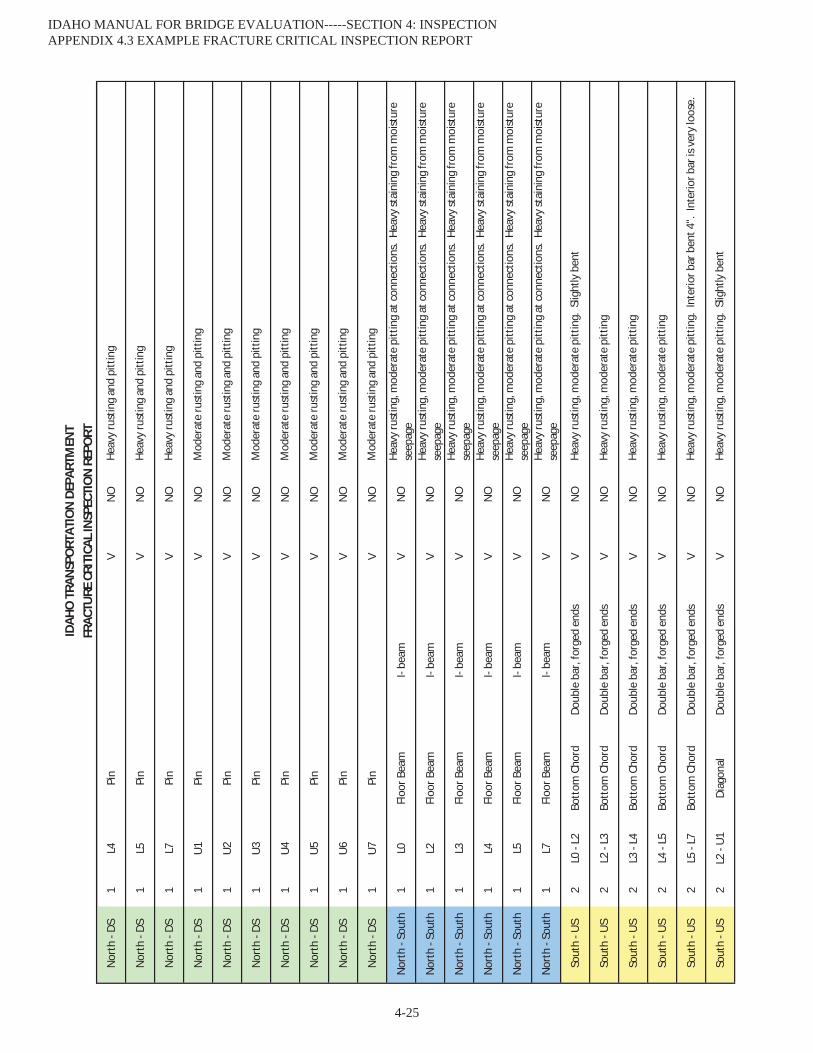
FRAC
TURE
CRI
TICA
L IN
SPEC
TIO
N R
EPO
RTID
AHO
TRA
NSP
ORT
ATIO
N D
EPAR
TMEN
T
Nor
th -
DS1
L4Pi
nV
NO
Nor
th -
DS1
L5Pi
nV
NO
Nor
th -
DS1
L7Pi
nV
NO
Nor
th -
DS1
U1
Pin
VN
O
Nor
th -
DS1
U2
Pin
VN
O
Nor
th -
DS1
U3
Pin
VN
O
Nor
th -
DS1
U4
Pin
VN
O
Nor
th -
DS1
U5
Pin
VN
O
Nor
th -
DS1
U6
Pin
VN
O
Nor
th -
DS1
U7
Pin
VN
O
Nor
th -
Sout
h1
L0Fl
oor B
eam
I- be
amV
NO
Nor
th -
Sout
h1
L2Fl
oor B
eam
I- be
amV
NO
Nor
th -
Sout
h1
L3Fl
oor B
eam
I- be
amV
NO
Nor
th -
Sout
h1
L4Fl
oor B
eam
I- be
amV
NO
Nor
th -
Sout
h1
L5Fl
oor B
eam
I- be
amV
NO
Nor
th -
Sout
h1
L7Fl
oor B
eam
I- be
amV
NO
Sout
h - U
S2
L0 -
L2Bo
ttom
Cho
rdDo
uble
bar
, for
ged
ends
VN
O
Sout
h - U
S2
L2 -
L3Bo
ttom
Cho
rdDo
uble
bar
, for
ged
ends
VN
O
Sout
h - U
S2
L3 -
L4Bo
ttom
Cho
rdDo
uble
bar
, for
ged
ends
VN
O
Sout
h - U
S2
L4 -
L5Bo
ttom
Cho
rdDo
uble
bar
, for
ged
ends
VN
O
Sout
h - U
S2
L5 -
L7Bo
ttom
Cho
rdDo
uble
bar
, for
ged
ends
VN
O
Sout
h - U
S2
L2 -
U1
Diag
onal
Doub
le b
ar, f
orge
d en
dsV
NO
Heav
y ru
stin
g, m
oder
ate
pitt
ing
Heav
y ru
stin
g, m
oder
ate
pitt
ing
Heav
y ru
stin
g, m
oder
ate
pitt
ing.
Int
erio
r bar
ben
t 4".
Int
erio
r bar
is v
ery
loos
e.
Heav
y ru
stin
g, m
oder
ate
pitt
ing.
Slig
htly
ben
t
Heav
y ru
stin
g, m
oder
ate
pitt
ing
at c
onne
ctio
ns.
Heav
y st
aini
ng fr
om m
oist
ure
seep
age
Heav
y ru
stin
g, m
oder
ate
pitt
ing
at c
onne
ctio
ns.
Heav
y st
aini
ng fr
om m
oist
ure
seep
age
Heav
y ru
stin
g, m
oder
ate
pitt
ing
at c
onne
ctio
ns.
Heav
y st
aini
ng fr
om m
oist
ure
seep
age
Heav
y ru
stin
g, m
oder
ate
pitt
ing
at c
onne
ctio
ns.
Heav
y st
aini
ng fr
om m
oist
ure
seep
age
Heav
y ru
stin
g, m
oder
ate
pitt
ing.
Slig
htly
ben
t
Heav
y ru
stin
g, m
oder
ate
pitt
ing
Mod
erat
e ru
stin
g an
d pi
ttin
g
Mod
erat
e ru
stin
g an
d pi
ttin
g
Mod
erat
e ru
stin
g an
d pi
ttin
g
Mod
erat
e ru
stin
g an
d pi
ttin
g
Heav
y ru
stin
g, m
oder
ate
pitt
ing
at c
onne
ctio
ns.
Heav
y st
aini
ng fr
om m
oist
ure
seep
age
Heav
y ru
stin
g, m
oder
ate
pitt
ing
at c
onne
ctio
ns.
Heav
y st
aini
ng fr
om m
oist
ure
seep
age
Heav
y ru
stin
g an
d pi
ttin
g
Heav
y ru
stin
g an
d pi
ttin
g
Heav
y ru
stin
g an
d pi
ttin
g
Mod
erat
e ru
stin
g an
d pi
ttin
g
Mod
erat
e ru
stin
g an
d pi
ttin
g
Mod
erat
e ru
stin
g an
d pi
ttin
g
2668
0 FC
Rep
ort 0
815.
xls
Page
3 o
f 6
IDAHO MANUAL FOR BRIDGE EVALUATION-----SECTION 4: INSPECTION APPENDIX 4.3 EXAMPLE FRACTURE CRITICAL INSPECTION REPORT
4-25
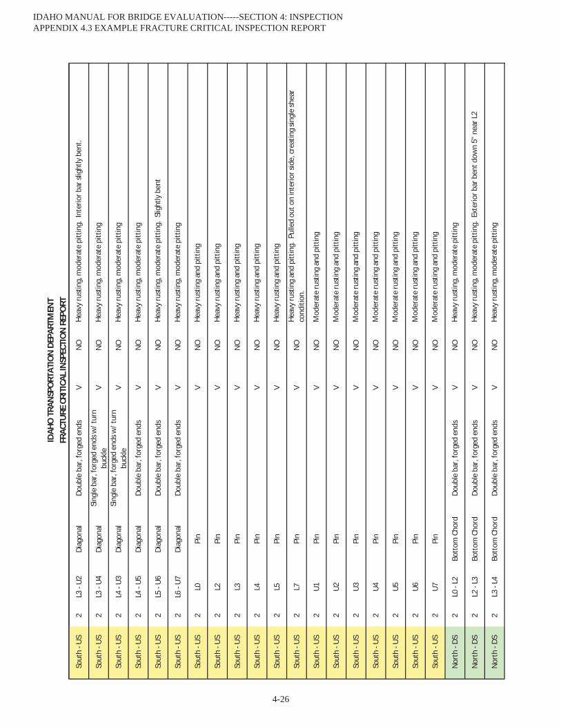
FRAC
TURE
CRI
TICA
L IN
SPEC
TIO
N R
EPO
RTID
AHO
TRA
NSP
ORT
ATIO
N D
EPAR
TMEN
T
Sout
h - U
S2
L3 -
U2
Diag
onal
Doub
le b
ar, f
orge
d en
dsV
NO
Sout
h - U
S2
L3 -
U4
Diag
onal
Sing
le b
ar, f
orge
d en
ds w
/ tur
n bu
ckle
VN
O
Sout
h - U
S2
L4 -
U3
Diag
onal
Sing
le b
ar, f
orge
d en
ds w
/ tur
n bu
ckle
VN
O
Sout
h - U
S2
L4 -
U5
Diag
onal
Doub
le b
ar, f
orge
d en
dsV
NO
Sout
h - U
S2
L5 -
U6
Diag
onal
Doub
le b
ar, f
orge
d en
dsV
NO
Sout
h - U
S2
L6 -
U7
Diag
onal
Doub
le b
ar, f
orge
d en
dsV
NO
Sout
h - U
S2
L0Pi
nV
NO
Sout
h - U
S2
L2Pi
nV
NO
Sout
h - U
S2
L3Pi
nV
NO
Sout
h - U
S2
L4Pi
nV
NO
Sout
h - U
S2
L5Pi
nV
NO
Sout
h - U
S2
L7Pi
nV
NO
Sout
h - U
S2
U1Pi
nV
NO
Sout
h - U
S2
U2Pi
nV
NO
Sout
h - U
S2
U3Pi
nV
NO
Sout
h - U
S2
U4Pi
nV
NO
Sout
h - U
S2
U5Pi
nV
NO
Sout
h - U
S2
U6Pi
nV
NO
Sout
h - U
S2
U7Pi
nV
NO
Nor
th -
DS2
L0 -
L2Bo
ttom
Cho
rdDo
uble
bar
, for
ged
ends
VN
O
Nor
th -
DS2
L2 -
L3Bo
ttom
Cho
rdDo
uble
bar
, for
ged
ends
VN
O
Nor
th -
DS2
L3 -
L4Bo
ttom
Cho
rdDo
uble
bar
, for
ged
ends
VN
O
Heav
y ru
stin
g, m
oder
ate
pitt
ing.
Ext
erio
r bar
ben
t dow
n 5"
nea
r L2
Heav
y ru
stin
g, m
oder
ate
pitt
ing
Mod
erat
e ru
stin
g an
d pi
ttin
g
Mod
erat
e ru
stin
g an
d pi
ttin
g
Mod
erat
e ru
stin
g an
d pi
ttin
g
Mod
erat
e ru
stin
g an
d pi
ttin
g
Mod
erat
e ru
stin
g an
d pi
ttin
g
Heav
y ru
stin
g, m
oder
ate
pitt
ing
Heav
y ru
stin
g an
d pi
ttin
g
Heav
y ru
stin
g an
d pi
ttin
g
Heav
y ru
stin
g an
d pi
ttin
g
Heav
y ru
stin
g an
d pi
ttin
g. P
ulle
d ou
t on
inte
rior s
ide,
cre
atin
g sin
gle
shea
r co
nditi
on.
Mod
erat
e ru
stin
g an
d pi
ttin
g
Mod
erat
e ru
stin
g an
d pi
ttin
g
Heav
y ru
stin
g, m
oder
ate
pitt
ing
Heav
y ru
stin
g, m
oder
ate
pitt
ing
Heav
y ru
stin
g, m
oder
ate
pitt
ing.
Slig
htly
ben
t
Heav
y ru
stin
g, m
oder
ate
pitt
ing
Heav
y ru
stin
g an
d pi
ttin
g
Heav
y ru
stin
g an
d pi
ttin
g
Heav
y ru
stin
g, m
oder
ate
pitt
ing.
Int
erio
r bar
slig
htly
ben
t.
Heav
y ru
stin
g, m
oder
ate
pitt
ing
2668
0 FC
Rep
ort 0
815.
xls
Page
4 o
f 6
IDAHO MANUAL FOR BRIDGE EVALUATION-----SECTION 4: INSPECTION APPENDIX 4.3 EXAMPLE FRACTURE CRITICAL INSPECTION REPORT
4-26
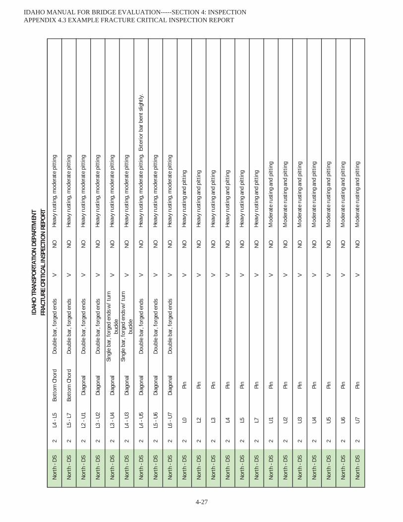
FRAC
TURE
CRI
TICA
L IN
SPEC
TIO
N R
EPO
RTID
AHO
TRA
NSP
ORT
ATIO
N D
EPAR
TMEN
T
Nor
th -
DS2
L4 -
L5Bo
ttom
Cho
rdDo
uble
bar
, for
ged
ends
VN
O
Nor
th -
DS2
L5 -
L7Bo
ttom
Cho
rdDo
uble
bar
, for
ged
ends
VN
O
Nor
th -
DS2
L2 -
U1
Diag
onal
Doub
le b
ar, f
orge
d en
dsV
NO
Nor
th -
DS2
L3 -
U2
Diag
onal
Doub
le b
ar, f
orge
d en
dsV
NO
Nor
th -
DS2
L3 -
U4
Diag
onal
Sing
le b
ar, f
orge
d en
ds w
/ tur
n bu
ckle
VN
O
Nor
th -
DS2
L4 -
U3
Diag
onal
Sing
le b
ar, f
orge
d en
ds w
/ tur
n bu
ckle
VN
O
Nor
th -
DS2
L4 -
U5
Diag
onal
Doub
le b
ar, f
orge
d en
dsV
NO
Nor
th -
DS2
L5 -
U6
Diag
onal
Doub
le b
ar, f
orge
d en
dsV
NO
Nor
th -
DS2
L6 -
U7
Diag
onal
Doub
le b
ar, f
orge
d en
dsV
NO
Nor
th -
DS2
L0Pi
nV
NO
Nor
th -
DS2
L2Pi
nV
NO
Nor
th -
DS2
L3Pi
nV
NO
Nor
th -
DS2
L4Pi
nV
NO
Nor
th -
DS2
L5Pi
nV
NO
Nor
th -
DS2
L7Pi
nV
NO
Nor
th -
DS2
U1
Pin
VN
O
Nor
th -
DS2
U2
Pin
VN
O
Nor
th -
DS2
U3
Pin
VN
O
Nor
th -
DS2
U4
Pin
VN
O
Nor
th -
DS2
U5
Pin
VN
O
Nor
th -
DS2
U6
Pin
VN
O
Nor
th -
DS2
U7
Pin
VN
O
Mod
erat
e ru
stin
g an
d pi
ttin
g
Mod
erat
e ru
stin
g an
d pi
ttin
g
Mod
erat
e ru
stin
g an
d pi
ttin
g
Mod
erat
e ru
stin
g an
d pi
ttin
g
Mod
erat
e ru
stin
g an
d pi
ttin
g
Mod
erat
e ru
stin
g an
d pi
ttin
g
Heav
y ru
stin
g an
d pi
ttin
g
Heav
y ru
stin
g an
d pi
ttin
g
Heav
y ru
stin
g an
d pi
ttin
g
Heav
y ru
stin
g an
d pi
ttin
g
Heav
y ru
stin
g an
d pi
ttin
g
Mod
erat
e ru
stin
g an
d pi
ttin
g
Heav
y ru
stin
g, m
oder
ate
pitt
ing
Heav
y ru
stin
g, m
oder
ate
pitt
ing
Heav
y ru
stin
g, m
oder
ate
pitt
ing.
Ext
erio
r bar
ben
t slig
htly
.
Heav
y ru
stin
g, m
oder
ate
pitt
ing
Heav
y ru
stin
g, m
oder
ate
pitt
ing
Heav
y ru
stin
g an
d pi
ttin
g
Heav
y ru
stin
g, m
oder
ate
pitt
ing
Heav
y ru
stin
g, m
oder
ate
pitt
ing
Heav
y ru
stin
g, m
oder
ate
pitt
ing
Heav
y ru
stin
g, m
oder
ate
pitt
ing
2668
0 FC
Rep
ort 0
815.
xls
Page
5 o
f 6
IDAHO MANUAL FOR BRIDGE EVALUATION-----SECTION 4: INSPECTION APPENDIX 4.3 EXAMPLE FRACTURE CRITICAL INSPECTION REPORT
4-27

FRAC
TURE
CRI
TICA
L IN
SPEC
TIO
N R
EPO
RTID
AHO
TRA
NSP
ORT
ATIO
N D
EPAR
TMEN
T
Nor
th -
Sout
h2
L0Fl
oor B
eam
I- be
amV
NO
Nor
th -
Sout
h2
L2Fl
oor B
eam
I- be
amV
NO
Nor
th -
Sout
h2
L3Fl
oor B
eam
I- be
amV
NO
Nor
th -
Sout
h2
L4Fl
oor B
eam
I- be
amV
NO
Nor
th -
Sout
h2
L5Fl
oor B
eam
I- be
amV
NO
Nor
th -
Sout
h2
L7Fl
oor B
eam
I- be
amV
NO
INSP
ECTI
ON
MET
HODS
SURF
ACE
PREP
ARAT
ION
S(V
) VIS
UAL
(NO
) NO
NE
(DP)
DYE
PEN
TRAN
T(W
B) W
IRE
BRU
SH(U
T) U
LTRA
SON
IC(G
R) G
RIN
DIN
G(M
P) M
AGN
ETIC
PAR
TICL
E(C
E) C
HEM
ICAL
(OT)
OTH
ER(S
B) S
AND
BLAS
TIN
G(C
H) C
HIPP
ING
HAM
MER
(OT)
OTH
ER
Heav
y ru
stin
g, m
oder
ate
pitt
ing
at c
onne
ctio
ns.
Heav
y st
aini
ng fr
om m
oist
ure
seep
age
Heav
y ru
stin
g, m
oder
ate
pitt
ing
at c
onne
ctio
ns.
Heav
y st
aini
ng fr
om m
oist
ure
seep
age
Heav
y ru
stin
g, m
oder
ate
pitt
ing
at c
onne
ctio
ns.
Heav
y st
aini
ng fr
om m
oist
ure
seep
age
Heav
y ru
stin
g, m
oder
ate
pitt
ing
at c
onne
ctio
ns.
Heav
y st
aini
ng fr
om m
oist
ure
seep
age
Heav
y ru
stin
g, m
oder
ate
pitt
ing
at c
onne
ctio
ns.
Heav
y st
aini
ng fr
om m
oist
ure
seep
age
Heav
y ru
stin
g, m
oder
ate
pitt
ing
at c
onne
ctio
ns.
Heav
y st
aini
ng fr
om m
oist
ure
seep
age
2668
0 FC
Rep
ort 0
815.
xls
Page
6 o
f 6
IDAHO MANUAL FOR BRIDGE EVALUATION-----SECTION 4: INSPECTION APPENDIX 4.3 EXAMPLE FRACTURE CRITICAL INSPECTION REPORT
4-28

IDAHO TRANSPORTATION DEPARTMENTUNDERWATER INSPECTION REPORT
Bridge Key: 19796 Structure Name: 99773A 1.71Feature Intersected: Boise River; N. Channel Location: 0.7 S. 3.0 W. Eagle
Facility Carried: Linder Road Admin Jurisdiction: 0101 ADA COUNTY HWY DISTRICT
Macs Seg: 002570 Milepost: 001.692 District: 3Latitude: N 43o 41’ 15” Longitude: W 116o 24’ 49” Owner: ADA COUNTY HWY DISTRICTCounty: 001 ADA Year Built: 1992
RPT_10/2014 1 of 3
Proposed UW Insp. Freq: 60 months Previous UW Insp. Freq: 60 months Previous UW Insp. Date: 8/26/2013
Reason for Proposed Changeto UW Insp. Freq: N/A
Items to Inspect: Bent 3
Foundation Type: Steel piles
Scour Countermeasures: Yes No If Yes, Describe:
Structural Details: Reinforced concrete footings supported by steel piles
Plans Available: General Plan andElevation
Substructure UnitDetails
Repair/RehabilitationDrawings
No PlansAvailable
Hydraulic Features & Characteristics: No significant hydraulic features at this bridge.
Inspection Method: Wet/Dry Suit Scuba Surface Supplied Air Other
Comments:No Comments
Inspection Level: Level I Level II Level III
Comments: Level I inspection over 100 percent of each underwater element. Level II inspection over 10 percent of each underwaterelement.
Specialized Equip: None required
Flow control located upstream or immediately downstream of structure? Yes No
Contact to flow control agency required to adequately inspect structure? Yes No
Flow Controlling Agency: Lucky Peak Dam
Contact: Park manager
Phone: (208) 343-0671
Bridge Contact:
Phone:
Team Leader (Print & Sign): Michael Banasiak P.E. Inspection Date: 8/26/2017
INSPECTION INFORMATION AND PROCEDURES
IDAHO MANUAL FOR BRIDGE EVALUATION-----SECTION 4: INSPECTION APPENDIX 4.4 EXAMPLE UNDERWATER INSPECTION REPORT
4-29
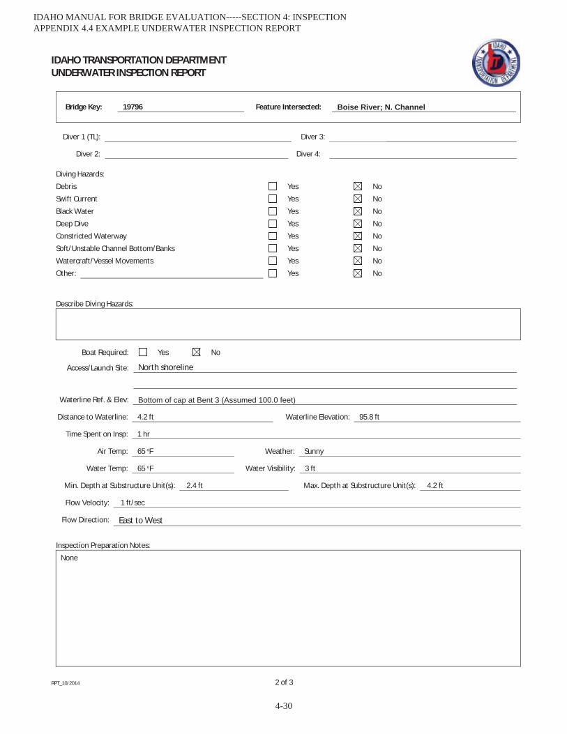
IDAHO TRANSPORTATION DEPARTMENTUNDERWATER INSPECTION REPORT
Bridge Key: 19796 Feature Intersected: Boise River; N. Channel
RPT_10/2014 2 of 3
Diver 1 (TL): Michael Banasiak Diver 3: Dylon Moss
Diver 2: Charles Euwema Diver 4:
Describe Diving Hazards:
Boat Required: Yes No
Access/Launch Site: North shoreline
Waterline Ref. & Elev: Bottom of cap at Bent 3 (Assumed 100.0 feet)
Distance to Waterline: 4.2 ft Waterline Elevation: 95.8 ft
Time Spent on Insp: 1 hr
Air Temp: 65 oF Weather: Sunny
Water Temp: 65 oF Water Visibility: 3 ft
Min. Depth at Substructure Unit(s): 2.4 ft Max. Depth at Substructure Unit(s): 4.2 ft
Flow Velocity: 1 ft/sec
Flow Direction: East to West
Inspection Preparation Notes:
None
Diving Hazards:
Debris Yes No
Swift Current Yes No
Black Water Yes No
Deep Dive Yes No
Constricted Waterway Yes No
Soft/Unstable Channel Bottom/Banks Yes No
Watercraft/Vessel Movements Yes No
Other: Yes No
IDAHO MANUAL FOR BRIDGE EVALUATION-----SECTION 4: INSPECTION APPENDIX 4.4 EXAMPLE UNDERWATER INSPECTION REPORT
4-30
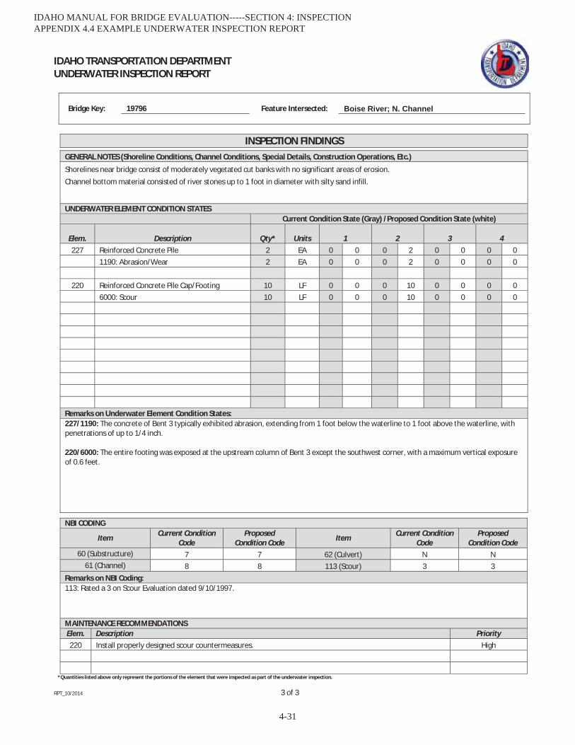
IDAHO TRANSPORTATION DEPARTMENTUNDERWATER INSPECTION REPORT
Bridge Key: 19796 Feature Intersected: Boise River; N. Channel
RPT_10/2014 3 of 3
*Quantities listed above only represent the portions of the element that were inspected as part of the underwater inspection.
INSPECTION FINDINGSGENERAL NOTES (Shoreline Conditions, Channel Conditions, Special Details, Construction Operations, Etc.)
Shorelines near bridge consist of moderately vegetated cut banks with no significant areas of erosion.Channel bottom material consisted of river stones up to 1 foot in diameter with silty sand infill.
UNDERWATER ELEMENT CONDITION STATESCurrent Condition State (Gray) /Proposed Condition State (white)
Elem. Description Qty* Units 1 2 3 4227 Reinforced Concrete Pile 2 EA 0 0 0 2 0 0 0 0
1190: Abrasion/Wear 2 EA 0 0 0 2 0 0 0 0
220 Reinforced Concrete Pile Cap/Footing 10 LF 0 0 0 10 0 0 0 06000: Scour 10 LF 0 0 0 10 0 0 0 0
Remarks on Underwater Element Condition States:227/1190: The concrete of Bent 3 typically exhibited abrasion, extending from 1 foot below the waterline to 1 foot above the waterline, withpenetrations of up to 1/4 inch.
220/6000: The entire footing was exposed at the upstream column of Bent 3 except the southwest corner, with a maximum vertical exposureof 0.6 feet.
NBI CODING
Item Current ConditionCode
ProposedCondition Code Item Current Condition
CodeProposed
Condition Code60 (Substructure) 7 7 62 (Culvert) N N
61 (Channel) 8 8 113 (Scour) 3 3Remarks on NBI Coding:113: Rated a 3 on Scour Evaluation dated 9/10/1997.
MAINTENANCE RECOMMENDATIONSElem. Description Priority220 Install properly designed scour countermeasures. High
IDAHO MANUAL FOR BRIDGE EVALUATION-----SECTION 4: INSPECTION APPENDIX 4.4 EXAMPLE UNDERWATER INSPECTION REPORT
4-31

UNDERWATER INSPECTIONBridge Key 19796 • Linder Road over N. Channel Boise RiverNear Eagle, Idaho • August 2017
Photograph 1: OverallView of Bridge, LookingWest.
Photograph 2: View ofBent 3, Looking South.
IDAHO MANUAL FOR BRIDGE EVALUATION-----SECTION 4: INSPECTION APPENDIX 4.4 EXAMPLE UNDERWATER INSPECTION REPORT
4-32

UNDERWATER INSPECTIONBridge Key 19796 • Linder Road over N. Channel Boise RiverNear Eagle, Idaho • August 2017
Photograph 3: TypicalCondition of Concreteat the Waterline.
IDAHO MANUAL FOR BRIDGE EVALUATION-----SECTION 4: INSPECTION APPENDIX 4.4 EXAMPLE UNDERWATER INSPECTION REPORT
4-33

IDAHO MANUAL FOR BRIDGE EVALUATION-----SECTION 4: INSPECTION APPENDIX 4.4 EXAMPLE UNDERWATER INSPECTION REPORT
4-34
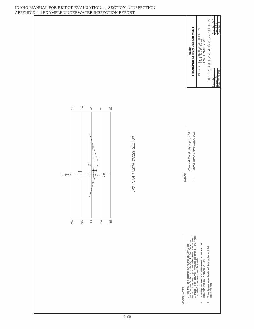
IDAHO MANUAL FOR BRIDGE EVALUATION-----SECTION 4: INSPECTION APPENDIX 4.4 EXAMPLE UNDERWATER INSPECTION REPORT
4-35
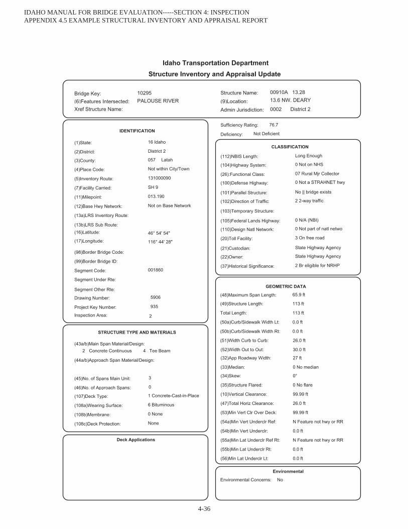
IDAHO MANUAL FOR BRIDGE EVALUATION-----SECTION 4: INSPECTION APPENDIX 4.5 EXAMPLE STRUCTURAL INVENTORY AND APPRAISAL REPORT
4-36
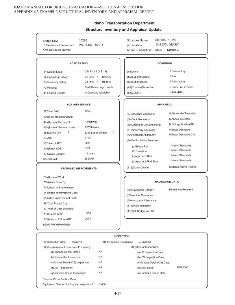
IDAHO MANUAL FOR BRIDGE EVALUATION-----SECTION 4: INSPECTION APPENDIX 4.5 EXAMPLE STRUCTURAL INVENTORY AND APPRAISAL REPORT
4-37

IDAHO MANUAL FOR BRIDGE EVALUATION-----SECTION 4: INSPECTION APPENDIX 4.5 EXAMPLE STRUCTURAL INVENTORY AND APPRAISAL REPORT
4-38
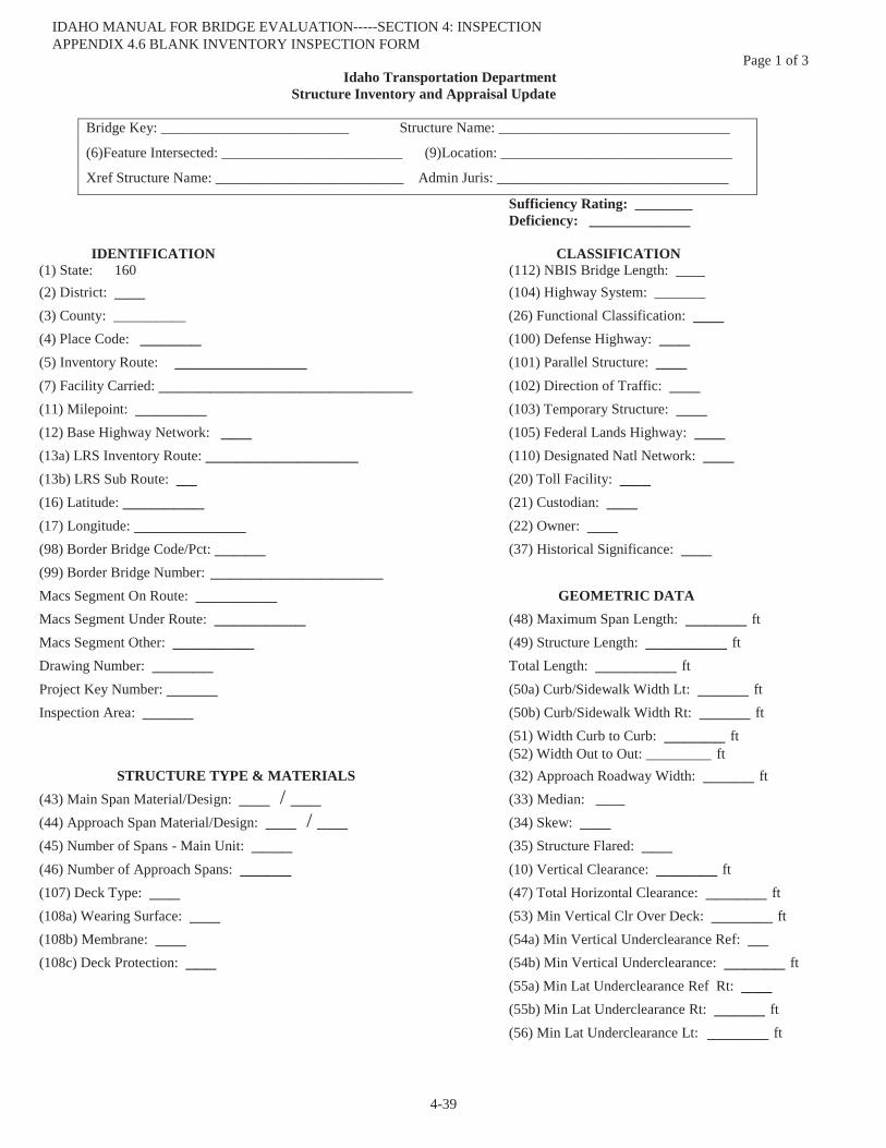
Page 1 of 3 Idaho Transportation Department
Structure Inventory and Appraisal Update
Bridge Key: __________________________ Structure Name: ________________________________
(6)Feature Intersected: _________________________ (9)Location: ________________________________
Xref Structure Name: __________________________ Admin Juris: ________________________________
Sufficiency Rating: ________ Deficiency: ______________
IDENTIFICATION CLASSIFICATION (1) State: 160 (112) NBIS Bridge Length: ____ (2) District: ___ (104) Highway System: _______ (3) County: __________ (26) Functional Classification: ___(4) Place Code: ______ (100) Defense Highway: ___(5) Inventory Route: _____________ (101) Parallel Structure: ___(7) Facility Carried: _________________________ (102) Direction of Traffic: ___(11) Milepoint: _______ (103) Temporary Structure: ___(12) Base Highway Network: ___ (105) Federal Lands Highway: ___(13a) LRS Inventory Route: _______________ (110) Designated Natl Network: ___(13b) LRS Sub Route: __ (20) Toll Facility: ___(16) Latitude: ________ (21) Custodian: ___(17) Longitude: ___________ (22) Owner: ___(98) Border Bridge Code/Pct: _____ (37) Historical Significance: ___(99) Border Bridge Number: _________________Macs Segment On Route: ________ GEOMETRIC DATAMacs Segment Under Route: _________ (48) Maximum Span Length: ______ ftMacs Segment Other: ________ (49) Structure Length: ________ ftDrawing Number: ______ Total Length: ________ ftProject Key Number: _____ (50a) Curb/Sidewalk Width Lt: _____ ftInspection Area: _____ (50b) Curb/Sidewalk Width Rt: _____ ft
(51) Width Curb to Curb: ______ ft(52) Width Out to Out: _________ ft
STRUCTURE TYPE & MATERIALS (32) Approach Roadway Width: _____ ft(43) Main Span Material/Design: ___ / ___ (33) Median: ____(44) Approach Span Material/Design: ___ / ___ (34) Skew: ___(45) Number of Spans - Main Unit: ____ (35) Structure Flared: ___(46) Number of Approach Spans: _____ (10) Vertical Clearance: ______ ft(107) Deck Type: ___ (47) Total Horizontal Clearance: ______ ft(108a) Wearing Surface: ___ (53) Min Vertical Clr Over Deck: ______ ft(108b) Membrane: ___ (54a) Min Vertical Underclearance Ref: __(108c) Deck Protection: ___ (54b) Min Vertical Underclearance: ______ ft
(55a) Min Lat Underclearance Ref Rt: ___(55b) Min Lat Underclearance Rt: _____ ft(56) Min Lat Underclearance Lt: ______ ft
IDAHO MANUAL FOR BRIDGE EVALUATION-----SECTION 4: INSPECTION APPENDIX 4.6 BLANK INVENTORY INSPECTION FORM
4-39
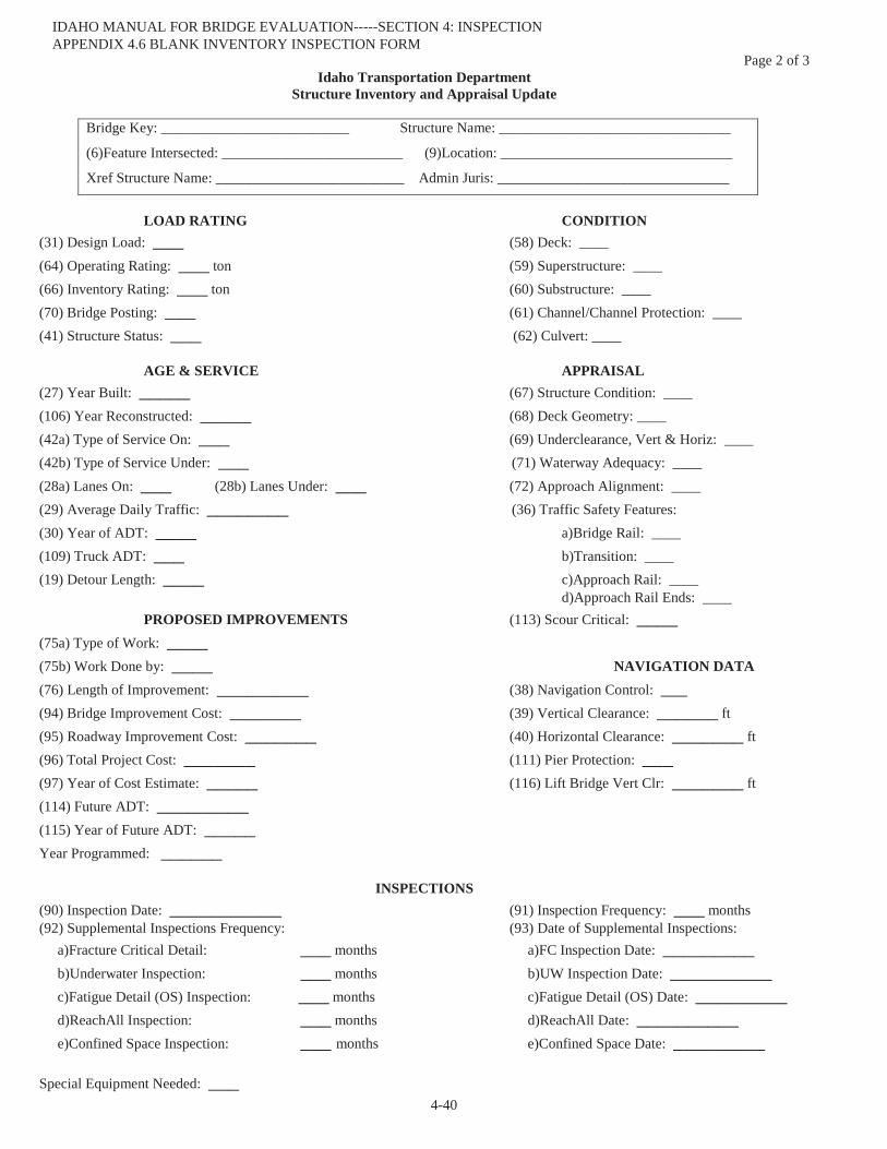
Page 2 of 3 Idaho Transportation Department
Structure Inventory and Appraisal Update
Bridge Key: __________________________ Structure Name: ________________________________
(6)Feature Intersected: _________________________ (9)Location: ________________________________
Xref Structure Name: __________________________ Admin Juris: ________________________________
LOAD RATING CONDITION(31) Design Load: ___ (58) Deck: ____ (64) Operating Rating: ___ ton (59) Superstructure: ____(66) Inventory Rating: ___ ton (60) Substructure: ____(70) Bridge Posting: ___ (61) Channel/Channel Protection: ____(41) Structure Status: ___ (62) Culvert: ____
AGE & SERVICE APPRAISAL (27) Year Built: _____ (67) Structure Condition: ____ (106) Year Reconstructed: _____ (68) Deck Geometry: ____ (42a) Type of Service On: ___ (69) Underclearance, Vert & Horiz: ____ (42b) Type of Service Under: ___ (71) Waterway Adequacy: ____ (28a) Lanes On: ___ (28b) Lanes Under: ___ (72) Approach Alignment: ____ (29) Average Daily Traffic: ________ (36) Traffic Safety Features: (30) Year of ADT: ____ a)Bridge Rail: ____(109) Truck ADT: ___ b)Transition: ____(19) Detour Length: ____ c)Approach Rail: ____
d)Approach Rail Ends: ____PROPOSED IMPROVEMENTS (113) Scour Critical: ____
(75a) Type of Work: ____(75b) Work Done by: ____ NAVIGATION DATA (76) Length of Improvement: _________ (38) Navigation Control: ___(94) Bridge Improvement Cost: _______ (39) Vertical Clearance: ______ ft(95) Roadway Improvement Cost: _______ (40) Horizontal Clearance: _______ ft(96) Total Project Cost: _______ (111) Pier Protection: ___(97) Year of Cost Estimate: _____ (116) Lift Bridge Vert Clr: _______ ft(114) Future ADT: _________(115) Year of Future ADT: _____Year Programmed: ______
INSPECTIONS (90) Inspection Date: ___________ (91) Inspection Frequency: ___ months(92) Supplemental Inspections Frequency: (93) Date of Supplemental Inspections:
a)Fracture Critical Detail: ___ months a)FC Inspection Date: _________b)Underwater Inspection: ___ months b)UW Inspection Date: __________c)Fatigue Detail (OS) Inspection: ___ months c)Fatigue Detail (OS) Date: _________d)ReachAll Inspection: ___ months d)ReachAll Date: __________e)Confined Space Inspection: ___ months e)Confined Space Date: _________
Special Equipment Needed: ___
IDAHO MANUAL FOR BRIDGE EVALUATION-----SECTION 4: INSPECTION APPENDIX 4.6 BLANK INVENTORY INSPECTION FORM
4-40
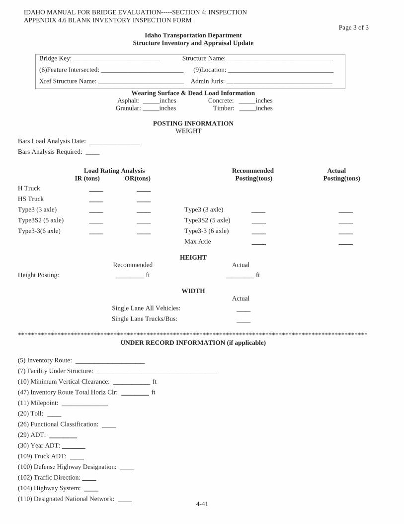
Page 3 of 3 Idaho Transportation Department
Structure Inventory and Appraisal Update
Bridge Key: __________________________ Structure Name: ________________________________
(6)Feature Intersected: _________________________ (9)Location: ________________________________
Xref Structure Name: __________________________ Admin Juris: ________________________________
Wearing Surface & Dead Load Information Asphalt: _____inches Concrete: _____ inches
Granular: _____inches Timber: _____inches
POSTING INFORMATION WEIGHT
Bars Load Analysis Date: ___________Bars Analysis Required: ___
Load Rating Analysis Recommended Actual IR (tons) OR(tons) Posting(tons) Posting(tons)
H Truck ___ ___ HS Truck ___ ___ Type3 (3 axle) ___ ___ Type3 (3 axle) ___ ___Type3S2 (5 axle) ___ ___ Type3S2 (5 axle) ___ ___Type3-3(6 axle) ___ ___ Type3-3 (6 axle) ___ ___
Max Axle ___ ___
HEIGHT Recommended Actual
Height Posting: ______ ft ______ ft
WIDTH Actual ___Single Lane All Vehicles:
Single Lane Trucks/Bus: ___
********************************************************************************************************** UNDER RECORD INFORMATION (if applicable)
(5) Inventory Route: _______________(7) Facility Under Structure: __________________________(10) Minimum Vertical Clearance: ________ ft(47) Inventory Route Total Horiz Clr: ______ ft(11) Milepoint: __________ (20) Toll: ___ (26) Functional Classification: ___ (29) ADT: ______(30) Year ADT: _____(109) Truck ADT: ___(100) Defense Highway Designation: ___ (102) Traffic Direction: ___ (104) Highway System: ___(110) Designated National Network: ___
IDAHO MANUAL FOR BRIDGE EVALUATION-----SECTION 4: INSPECTION APPENDIX 4.6 BLANK INVENTORY INSPECTION FORM
4-41

Idaho Transportation DepartmentPontis Field Inspection Report
Bridge Key: __________________________ Structure Name: ________________________________Feature Intersected: ________________________ Location: ________________________________
Admin Jurisdiction: ________________________________Xref Structure Name: _______________________ District: ________________________________
Element Description Env Total Unit %State %State %State %State %State
Notes:______________________________________________________________________________________________________________________________________________________________________________________________________________________________________________________________________________________________________________________________________________________________________________________________________________________________________________________________________________________________________________________________________________________________________________________________________________________________________________________
______________________________________________________________________________________________________________________________________________________________________________________________________________________________________________________________________________________________________________________________________________________________________________________________________________________________________________________________________________________________________________________________________________________________________________________________________________________________________________________
______________________________________________________________________________________________________________________________________________________________________________________________________________________________________________________________________________________________________________________________________________________________________________________________________________________________________________________________________________________________________________________________________________________________________________________________________________________________________________________
______________________________________________________________________________________________________________________________________________________________________________________________________________________________________________________________________________________________________________________________________________________________________________________________________________________________________________________________________________________________________________________________________________________________________________________________________________________________________________________
IDAHO MANUAL FOR BRIDGE EVALUATION-----SECTION 4: INSPECTION APPENDIX 4.6 BLANK INVENTORY INSPECTION FORM
4-42
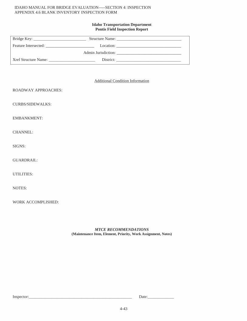
Idaho Transportation DepartmentPontis Field Inspection Report
Bridge Key: __________________________ Structure Name: ________________________________
Feature Intersected: ________________________ Location: ________________________________
Admin Jurisdiction: ________________________________
Xref Structure Name: _______________________ District: ________________________________
Additional Condition Information
ROADWAY APPROACHES:
CURBS/SIDEWALKS:
EMBANKMENT:
CHANNEL:
SIGNS:
GUARDRAIL:
UTILITIES:
:
WORK ACCOMPLISHED:
MTCE RECOMMENDATIONS(Maintenance Item, Element, Priority, Work Assignment, Notes)
Inspector:___________________________________________________ Date:_____________
IDAHO MANUAL FOR BRIDGE EVALUATION-----SECTION 4: INSPECTION APPENDIX 4.6 BLANK INVENTORY INSPECTION FORM
4-43

IDAHO TRANSPORTATION DEPARTMENTINSPECTION FORM
DISTRICT NO.
BRIDGE KEY: STRUCTURE NO:FEATURES INTERSECTED:LOCATION:
TYPE OF INSPECTIONDAMAGEUNDER BRIDGE INSPECTION TRUCK (UBIT)IN DEPTHSUPPLEMENTAL INSPECTION
DECK:
SUPERSTRUCTURE:
BEARINGS:
SUBSTRUCTURE:
EXPANSION JOINTS:
NOTES TO BAME:
MISCELLANEOUS ITEMS:
WORK ACCOMPLISHED:
MTCE RECOMMENDATIONS:
INSPECTOR’S SIGNATURE: DATE:
IDAHO MANUAL FOR BRIDGE EVALUATION-----SECTION 4: INSPECTION APPENDIX 4.7 BLANK NON-SI&A INSPECTION FORM
4-44
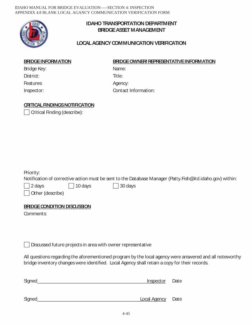
IDAHO TRANSPORTATION DEPARTMENT BRIDGE ASSET MANAGEMENT
LOCAL AGENCY COMMUNICATION VERIFICATION
BRIDGE INFORMATION BRIDGE OWNER/REPRESENTATIVE INFORMATION Bridge Key: Name:
District: Title: Features: Agency:
Inspector: Contact Information:
CRITICAL FINDINGS NOTIFICATION Critical Finding (describe):
Priority: Notification of corrective action must be sent to the Database Manager ([email protected]) within:
2 days 10 days 30 days Other (describe)
BRIDGE CONDITION DISCUSSION Comments:
Discussed future projects in area with owner representative
All questions regarding the aforementioned program by the local agency were answered and all noteworthy bridge inventory changes were identified. Local Agency shall retain a copy for their records. Signed Inspector Date Signed Local Agency Date
IDAHO MANUAL FOR BRIDGE EVALUATION-----SECTION 4: INSPECTION APPENDIX 4.8 BLANK LOCAL AGANCY COMMUNICATION VERIFICATION FORM
4-45

IDAHO TRANSPORTATION DEPARTMENT BRIDGE ASSET MANAGEMENT
CRITICAL FINDING COMMUNICATION
BRIDGE INFORMATION DISTRICT REPRESENTATIVE INFORMATION Bridge Key: Name: District: Title: Features: Inspector:
CRITICAL FINDINGS NOTIFICATION Critical Finding (describe):
Priority: Notification of corrective action must be sent to the Database Manager ([email protected]) within:
days days 30 days ther (describe)
IDAHO MANUAL FOR BRIDGE EVALUATION-----SECTION 4: INSPECTION APPENDIX 4.9 BLANK CRITICAL FINDING COMMUNICATION FORM
4-46

SCOUR COMMITTEE ASSESSMENT FLOW CHART BRIDGES REQUIRING A SCOUR EVALUATION (ITEM 113 = 6)
Bridge foundations (including piles) are on dry
land well above flood water elevation?
Item 113 = 9
Bridge is a single span with Channel Pro
or Bridge is over an irrigation canal?
or Bridge is over a quiescent pool such as a wetland, pond, or lake?
or Bridge has spread footing founded on highly scour resistant rock?
or Bridge has deep footings outside the main channel and lateral migration or stream stability is not an issue?
or Bridge foundations determined to be stable for the assessed scour condition?
Yes
No
No
Foundation type is able to be determined?
Item 113 =
Item 113 = U (Use Unknown Foundations Risk Assessment Flow Chart to determine high/low risk)
No
Yes
Send to consultant to perform scour
calculations and determine Item 113.
Bridge is exhibiting scour?
No
Yes
Go to page 2
Yes
IDAHO MANUAL FOR BRIDGE EVALUATION-----SECTION 4: INSPECTION APPENDIX 4.10 INITIAL SCOUR ASSESSMENT FLOW CHART
4-47
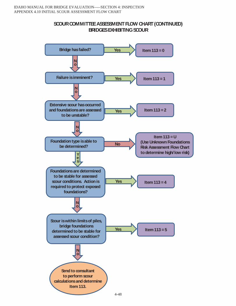
SCOUR COMMITTEE ASSESSMENT FLOW CHART (CONTINUED) BRIDGES EXHIBITING SCOUR
Item 113 = 1 Failure is imminent?
Bridge has failed?
Scour is within limits of piles, bridge foundations
determined to be stable for assessed scour condition?
Yes
No
Foundations are determined to be stable for assessed
scour conditions. Action is required to protect exposed
foundations?
Yes Item 113 = 2
No
Extensive scour has occurred and foundations are assessed
to be unstable?
Yes Item 113 = 4
No
Yes
Yes
No
Foundation type is able to be determined?
Item 113 = 0
Item 113 = U (Use Unknown Foundations Risk Assessment Flow Chart to determine high/low risk)
No
Yes
Item 113 = 5
Send to consultant to perform scour
calculations and determine Item 113.
No
IDAHO MANUAL FOR BRIDGE EVALUATION-----SECTION 4: INSPECTION APPENDIX 4.10 INITIAL SCOUR ASSESSMENT FLOW CHART
4-48

UNKNOWN FOUNDATIONS BRIDGES RISK ASSESSMENT FLOW CHART
Channel Protection (Item 61)
Waterway Adequacy(Item 71)
Yes
Yes
No
No
< 5
< 5
< 7
< 7
High
High
High
Low Low
No
Yes
Number of Spans
(Item 45 + 46) > 3 Review by Scour
Committee
No
YesHigh
Waterway Adequacy (Item 71)
& Channel
Protection (Item 61)
Number of Spans = 1 Number of Spans = 2 or 3
Waterway Adequacy (Item 71)
& Channel
Protection (Item 61)
& Detour Length
(Item 19) &
ADT (Item 29)
> 10
> 100
< 7
< 7
Yes
No
No
High Scour Committee has determined that exhibited scour
warrants High Risk monitoring. Undermining is minimal and foundation type is unable to be determined.
Yes
IDAHO MANUAL FOR BRIDGE EVALUATION-----SECTION 4: INSPECTION APPENDIX 4.11 UNKNOWN FOUNDATIONS SCOUR FLOW CHART
4-49

PAGE INTENTIONALLY LEFT BLANK
IDAHO MANUAL FOR BRIDGE EVALUATIONSECTION 6: LOAD RATING
TABLE OF CONTENTS
6-i
6.0—LOAD RATING PROCEDURES ...............................................................................................................................1
6.0.1—Abbreviations........................................................................................................................................................1 6.0.2—General Load Rating Criteria................................................................................................................................2 6.0.3—Load Rating Software and Analysis Engine .........................................................................................................2 6.0.4—Required Deliverables...........................................................................................................................................3
6.0.4.1—New/Replacement Bridge Projects, or Existing Bridges without a BrR™ File .............................................3 6.0.4.2—Rehabilitated Bridges.....................................................................................................................................3
6.0.5—Rating Results and Rating Units ...........................................................................................................................4 6.0.6—Quality Assurance and Quality Control ................................................................................................................4 6.0.7—Rating Model ........................................................................................................................................................5
6.0.7.1—Prestressed Girders ........................................................................................................................................5 6.0.7.2—Steel Girders ..................................................................................................................................................6 6.0.7.3—Reinforced Concrete Girders .........................................................................................................................6 6.0.7.4—Reinforced Concrete Frames and Box Structures ..........................................................................................6 6.0.7.5—Corrugated Metal Decks and Concrete Filled Grid Decks.............................................................................9 6.0.7.6—Corrugated Metal Culverts (Pipes, Arches, Boxes, etc.)................................................................................9 6.0.7.7—Railroad Flatcar & Boxcar Bridges................................................................................................................9
6.1—SCOPE.........................................................................................................................................................................9 6.1.1—Assumptions .........................................................................................................................................................9 6.1.2—Condition of Bridge Members ............................................................................................................................10 6.1.3—Evaluation Methods ............................................................................................................................................10 6.1.4—Bridges with Unknown Structural Components .................................................................................................10
6.1.4.1—Corrugated Metal Pipe and Arches ..............................................................................................................12 6.1.4.2—Steel and Timber Bridges ............................................................................................................................12
6.1.5—Component-Specific Evaluation .........................................................................................................................12 6.1.5.1—Decks ...........................................................................................................................................................12 6.1.5.2—Substructures................................................................................................................................................12
6.1.8—Qualifications and Responsibilities.....................................................................................................................12 6.1.9—Documentation of Load Rating...........................................................................................................................12
PART A—LOAD AND RESISTANCE FACTOR RATING............................................................................................13 6A.1—INTRODUCTION ..................................................................................................................................................13
6A.1.2—Scope................................................................................................................................................................13 6A.1.5—Load and Resistance Factor Rating..................................................................................................................13
6A.2—LOADS FOR EVALUATION ...............................................................................................................................13 6A.2.2—Permanent Loads and Load Factors .................................................................................................................13
6-ii IDAHO MANUAL FOR BRIDGE EVALUATION
6A.2.2.1—Dead Loads: DC and DW..........................................................................................................................13 6A.2.2.3—Load Factors .............................................................................................................................................14
6A.2.3—Transient Loads................................................................................................................................................14 6A.2.3.1—Vehicular Live Loads (Gravity Loads): LL...............................................................................................14 6A.2.3.2—Application of Vehicular Live Load .........................................................................................................15
6A.4—LOAD RATING PROCEDURES ..........................................................................................................................15 6A.4.1—Introduction......................................................................................................................................................15 6A.4.2—General Load Rating Equation.........................................................................................................................16
6A.4.2.2—Limit States ...............................................................................................................................................16 6A.4.2.3—Condition Factor: c..................................................................................................................................17
6A.5—CONCRETE STRUCTURES.................................................................................................................................17 6A.5.8—Evaluation for Shear ........................................................................................................................................17 6A.5.12—Rating of Reinforced Concrete Box Culverts ................................................................................................17
6A.6—STEEL STRUCTURES..........................................................................................................................................17 6A.8—POSTING OF BRIDGES .......................................................................................................................................17 PART B—ALLOWABLE STRESS RATING AND LOAD FACTOR RATING ............................................................18 6B.5—NOMINAL CAPACITY: C ....................................................................................................................................18
6B.5.2—Allowable Stress Method .................................................................................................................................18 6B.5.2.7—Timber.......................................................................................................................................................18
6B.5.3—Load Factor Method.........................................................................................................................................18 6B.5.3.1—Structural Steel ..........................................................................................................................................18 6B.5.3.2—Reinforced Concrete..................................................................................................................................18 6B.5.3.3—Prestressed Concrete .................................................................................................................................19
6B.6—LOADINGS ............................................................................................................................................................19 6B.6.1—Dead Load: D ...................................................................................................................................................19 6B.6.2—Rating Live Load .............................................................................................................................................19
6B.6.2.2—Truck Loads ..............................................................................................................................................20 6B.6.3—Distribution of Loads .......................................................................................................................................20
6B.7—POSTING OF BRIDGES........................................................................................................................................21 6B.7.1—General .............................................................................................................................................................21
6B.7.1.1—Posting and Closure Procedures of ITD Maintained Structures................................................................21 6B.7.1.2—Posting and Closure Procedures of Locally Owned Structures .................................................................22 6B.7.1.3—Emergency Posting of Weight Restrictions on Structures ........................................................................22
6B.7.2—Posting Loads...................................................................................................................................................23 6B.7.3—Posting Analysis...............................................................................................................................................23 6B.7.4—Regulatory Signs ..............................................................................................................................................23
6C.1—REFERENCES .......................................................................................................................................................23
SECTION 6: LOAD RATING 6-iii
APPENDIX 6.1.1—EXAMPLE LRFR LOAD RATING SUMMARY FORM 6-24
APPENDIX 6.1.2—LRFR LOAD RATING SUMMARY DIRECTIONS 6-26
APPENDIX 6.1.3—EXAMPLE LFR LOAD RATING SUMMARY FORM 6-29
APPENDIX 6.1.4—LFR LOAD RATING SUMMARY DIRECTIONS 6-31
APPENDIX 6.1.5—EXAMPLE ENGINEERING JUDGEMENT LOAD RATING SUMMARY FORM 6-34
APPENDIX 6.1.6—EXAMPLE LFR LOAD RATING SUMMARY FORM FOR CULVERT > 8' OF FILL 6-36
APPENDIX 6.1.7—EXAMPLE CMP LFR LOAD RATING SUMMARY FORM 6-37
APPENDIX 6.1.8—EXAMPLE CMP LRFR LOAD RATING SUMMARY FORM 6-39
APPENDIX 6.2.1—IDAHO LEGAL TRUCK SCHEMATICS 6-41
APPENDIX 6.2.2—121KIP TRUCK SCHEMATIC 6-42
APPENDIX 6.2.3—UNDER BRIDGE INSPECTION TRUCK SCHEMATIC 6-43
APPENDIX 6.2.4—UNDER BRIDGE INSPECTION TRUCK SCHEMATIC 6-44
APPENDIX 6.3.1—VIRTIS™ SETUP TUTORIAL 6-45
APPENDIX 6.3.2—CREATING A NEW BRIDGE IN VIRTIS™ 6-53
APPENDIX 6.3.3—ENTERING DESCRIPTION DATA IN VIRTIS™ 6-55
APPENDIX 6.3.4—VIRTIS™ IMPORT EXPORT DELETE TUTORIAL 6-59
APPENDIX 6.3.5—MODIFICATIONS TO STANDARD VIRTIS™ SETTINGS 6-61
APPENDIX 6.3.6—ANALYZE AND VIEW VIRTIS™ RESULTS TUTORIAL 6-63
APPENDIX 6.3.7—USING NON-STANDARD GAUGES WITH VIRTIS™ 6-66
APPENDIX 6.4.1—IN-HOUSE REHABILITATION RATINGS CHECKLIST 6-70

6-iv IDAHO MANUAL FOR BRIDGE EVALUATION
PAGE INTENTIONALLY LEFT BLANK

SECTION 6: LOAD RATING 6-1
6.0—LOAD RATING PROCEDURES
The procedures and requirements in Section 6: Load Rating shall be adhered to by anyone conducting load ratingsfor the Idaho Transportation Department.
Refer to the Idaho Transportation Department Bridge Design LRFD Manual (BDM) Article 0.3 and Article 0.4 for submittal procedures on load rating of new/replacement bridges and bridge rehabilitation projects.
Questions about this section or Idaho Transportation Department (ITD) load rating issues shall be directed to the ITD Load Rating Engineer.
Tisha HydeITD Load Rating Engineer(208) [email protected]
6.0.1—Abbreviations
ASD – Allowable Stress Design
ASR – Allowable Stress Rating
BAM – ITD Bridge Asset Management Section
BDM – ITD Bridge Design LRFD Manual: The ITD LRFD Bridge design policies which can be found at the following link: http://itd.idaho.gov/bridge/?target=LRFD-bridge-manual
BrM™ – AASHTOWare Bridge Management™ software (formerly known as Pontis™): Database used by ITD to store bridge inspection and load rating data
BrR™ – AASHTOWare Bridge Rating™ software (formerly known as Virtis™): ITD preferred load rating software
DC – Dead load of structural components and nonstructural attachments
DW – Dead load of wearing surfaces and utilities
EV – Emergency Vehicle as defined by the FAST Act (EV2, EV3)
FHWA – Federal Highway Administration
IR – Inventory Rating
ITD – Idaho Transportation Department
LFD – Load Factor Design
LFR – Load Factor Rating
LHTAC – Local Highway Technical Assistance Council
LRFD – Load and Resistance Factor Design
LRFR – Load and Resistance Factor Rating
LRS – Load Rating Summary: Form used by ITD to report load rating results
MBE – AASHTO Manual for Bridge Evaluation
6-2 IDAHO MANUAL FOR BRIDGE EVALUATION
MUTCD – Manual on Uniform Traffic Control Devices
NBI – National Bridge Inventory
NDS – National Design Specification for Wood Construction
NRL – Notional Rating Load
OR – Operating Rating
PS&E – Plans, Specifications, and Estimate
QA – Quality Assurance
QC – Quality Control
RCB – Reinforced Concrete Box
RCF – Reinforced Concrete Frame
SHV – Single Unit Specialized Hauling Vehicles (SU4, SU5, SU6, and SU7)
SI&A – Structural Inventory and Appraisal
6.0.2—General Load Rating Criteria
The load rating of new bridges or existing bridges with modifications shall be completed within 90 days after the notification of completion of the work for State or Federal agency bridges and within 180 days after the notification of completion of the work for all other bridges.
Bridges requiring a load rating that are added to the ITD inventory due to a jurisdictional change shall be completedwithin 90 days after the inventory inspection for State or Federal agency bridges and within 180 days of the inventory inspection for all other bridges. Time extensions may be accepted in extenuating circumstances as approved by the FHWA.
All load ratings shall be in accordance with the MBE version currently used by ITD as supplemented by this manual.
6.0.3—Load Rating Software and Analysis Engine
Load ratings shall be done with the most current version of BrR™ as licensed by ITD. Reinforced concrete, prestressed concrete and steel bridges shall be analyzed in BrR™ utilizing the AASHTO engine, unless otherwise approved by ITD. All timber bridges shall be analyzed in BrR™ utilizing the Madero engine. If the structure cannot be load rated with BrR™, the ITD Load Rating Engineer shall be contacted for guidance on what load rating program should be used.
The BrR™ software is an AASHTOWare product and can be obtained by contacting AASHTO. The order form can be found at:
http://www.aashtoware.org
The BrR™ Special Consultant License can be purchased to do work for ITD. Please follow the steps below to obtain a BrR™ Special Consultant License.
1. Fill out the form at the link shown above and e-mail it to the AASHTO e-mail address listed on the form.
2. Send a copy of the e-mail to the ITD Load Rating Engineer: [email protected]
There are several Appendices regarding the use of the BrR™ software they can be found as follows:
SECTION 6: LOAD RATING 6-3
Appendix 6.3.1—VIRTIS™ SETUP TUTORIALAppendix 6.3.2—CREATING A NEW BRIDGE IN VIRTIS™Appendix 6.3.3—ENTERING DESCRIPTION DATA IN VIRTIS™Appendix 6.3.4—VIRTIS™ IMPORT EXPORT DELETE TUTORIALAppendix 6.3.5—MODIFICATIONS TO STANDARD VIRTIS™ SETTINGSAppendix 6.3.6—ANALYZE AND VIEW VIRTIS™ RESULTS TUTORIALAppendix 6.3.7—USING NON-STANDARD GAUGES WITH VIRTIS™
Appendices 6.3.1-6.3.7 were created in Virtis™ version 6.3 or earlier which is no longer the current version. Some screenshots and instructions may vary. Any inconsistencies that may affect the load rating shall be brought to the attention of the Load Rating Engineer prior to completing the load rating.
New corrugated metal structures shall be analyzed using the appropriate CMP spreadsheet originally developed by the Ohio Department of Transportation, as modified by ITD for the Idaho rating trucks; a copy of which can be obtained by contacting the ITD Load Rating Engineer.
6.0.4—Required Deliverables
6.0.4.1—New/Replacement Bridge Projects, or Existing Bridges without a BrR™ File
Refer to the BDM Article 0.3 and Article 0.4 for submittal procedures on load rating of new/replacement bridges. Load rating submittals for new/replacement bridges, or existing bridges which do not have an existing BrR™ file, shall require the following deliverables:
1. BrR™ file (no hard copy; XML electronic file only), or CMP spreadsheet (.xlxs and pdf)
2. Stamped and signed Load Rating Summary (LRS) form (hard copy and PDF format). An electronic copy of the LRS can be obtained by contacting the ITD Load Rating Engineer or downloaded using the following links(ASR/LFR, LRFR or CMP LFR, CMP LRFR). Example forms and directions on filling them out can be found in the following appendices:
Appendix 6.1.1—EXAMPLE LRFR LRS FORMAppendix 6.1.2—LRFR LRS DIRECTIONS Appendix 6.1.3—EXAMPLE LFR LRS FORMAppendix 6.1.4—LFR LRS DIRECTIONSAppendix 6.1.5—EXAMPLE ENGINEERING JUDGEMENT LRS FORMAppendix 6.1.6—EXAMPLE LFR LRS FOR CULVERTS WITH MORE THAN 8’ FILLAppendix 6.1.7—EXAMPLE CMP LFR LRSFORMAppendix 6.1.8—EXAMPLE CMP LRFR LRS FORM
3. Supporting calculations. If the rating is done in BrR™, supporting calculations shall be included in the Member Description as shown in Appendix 6.3.3. If the supporting calculations are too cumbersome to put in the Member Description, they may be submitted as a separate document in PDF format. Examples of this are LRFD live load distribution factors. Calculations for live load distribution factors do not need to be shown if they are automatically calculated by BrR™ from the bridge typical section.
4. Independent calculations for design truck inventory rating factors less than 0.90 or greater than 1.50 shall be submitted per Article 6.0.6.
5. For new/replacement bridges, the PS&E plans (11x17 hard copy or PDF format), and the approved shop drawings (PDF format).
6.0.4.2—Rehabilitated Bridges
All bridge rehabilitation projects shall have their load rating reviewed and updated as necessary. The load rating file should be updated to reflect the rehabilitation project changes, such as changes in wearing surface depth and/or unit weight, and rail retrofits.
6-4 IDAHO MANUAL FOR BRIDGE EVALUATION
Refer to the BDM Article 0.3 and Article 0.4 for submittal procedures on load rating of bridge rehabilitation projects. For bridge rehabilitation projects designed by ITD staff, refer to the checklist in Appendix 6.4.1 for the required steps for updating the BrR™ file. Load rating submittals for rehabilitated bridges shall require the following deliverables:
1. Updated BrR™ file (no hard copy; XML electronic file only).
2. Stamped (not necessary for minor rehabilitations) and signed Load Rating Summary (LRS) form (hard copy and PDF format). An electronic copy of the LRS can be obtained by contacting the ITD Load Rating Engineer or downloaded using the following links (ASR/LFR, LRFR). Examples of ITD LRS forms and directions on how to fill them out can be found in Appendices 6.1.1-6.1.4. The LRS is not required to be stamped by the bridge rehabilitation project designer.
3. Any supporting calculations (PDF format).
4. Independent calculations for design truck inventory rating factors less than 0.90 or greater than 1.50 do not need to be submitted.
5. The bridge rehabilitation project plans (11x17 hard copy or PDF format).
6.0.5—Rating Results and Rating Units
All rating results shall be reported in English units on the LRS form. BrR™ allows the rater to toggle between Metric and English units in the load rating summary output.
The live load models for load rating shall be evaluated under the rating criteria listed in Tables 6A.2.3.1-1, 6A.2.3.1-2, and 6B.6.2-1 and summarized in the appropriate Load Rating Summary form, found in Appendices 6.1.1-6.1.4.
Bridge plans in English units shall be input into the rating software using English units and the rating results shall be reported in English Tons. Bridge plans in Metric units may be input into the rating software using Metric or English units, but the rating results shall be reported in English Tons.
6.0.6—Quality Assurance and Quality Control
All load ratings by consultants must have a load rater, a checker, and a QC engineer. Either the load rater or the checker must be a registered Professional Engineer licensed in the state of Idaho.
All new load ratings by ITD staff (Bridge Design or Bridge Asset Management) that do not have a BrR™ filerequire a load rater and a checker, at least one of which must be a registered Professional Engineer licensed in the state of Idaho. The QC of the load rating shall be performed by the ITD Bridge Asset Management staff.
All load ratings that are required due to the rehabilitation of a structure done by ITD staff (Bridge Design or Bridge Asset Management) require a load rater and a checker, at least one of which must be a registered Professional Engineer licensed in the state of Idaho. The exception to this is if the rehabilitation is limited to the deck. In this case, only a load rater and QC person are required. The QC of the load rating shall be performed by the ITD Bridge Asset Management staff. A checklist for ITD rehabilitation load ratings that have an existing BrR™ file can be found in Appendix 6.4.1.
For bridge load ratings that are based on design plans and/or shop drawings; if the inventory rating factor for the design vehicle is less than 0.90 or greater than 1.50, independent calculations for the design truck must be submitted with the load rating package for the controlling location on the controlling member for the controlling limit state.
The independent calculations shall be performed for the dead loads, design truck live load, and capacities by hand calculations or by load rating software other than BrR™.
No portion of the independent calculations shall be taken from the BrR™ output. A short description of the reason the structure rates low or high must also be included with the rating package (ex: code has changed significantly since the time this structure was built, this structure was designed for future loads that are not currently on the bridge, etc.)
For bridge load ratings that are based on bridge measurements from field sketches, independent calculations do not need to be performed for any rating factor.

SECTION 6: LOAD RATING 6-5
6.0.7—Rating Model
Bridges modeled in BrR™ shall use a girder system definition when possible. Single line girder analysis shall not be conducted unless approved in advance by the ITD Load Rating Engineer.
All primary superstructure members shall be load rated. For girder type bridges, load rating shall be performed for the girders and stringer/floor beam systems, if applicable. Load rating of cross-beams, diaphragms, and cross-frames shall not be performed unless the bridge has curved girders or other special circumstances. This does not apply to girders with minor curvature as defined by LRFD.
Concrete bridge decks need not routinely be evaluated, but timber and corrugated metal decks shall be evaluated per Article 6.1.5.1. Substructures need not routinely be evaluated per Article 6.1.5.2.
Model each simple span as a separate, single span superstructure. Model a continuous span as a multi-span superstructure. Restraint moments for continuous girders shall not be considered, except for cantilevered spans. Only one superstructure model is necessary for spans that are identical.
Example 1: Simple 2 span bridge. Both spans are identical (span length, typical section, applied loads, etc.). Only one superstructure model is necessary.
Example 2: Simple 3 span bridge. Spans 1 & 3 are identical, but Span 2 is longer. One superstructure model representing Spans 1 & 3 and one superstructure model representing Span 2 are necessary.
Simple span bridges modeled in BrR™ shall not have the deck reinforcement input into the model.Varied Girder Spacing for LFR – In the case where girder spacing varies, the live load distribution factor shall be
calculated using the spacing at the maximum third point along the span.For bridges with a composite concrete deck, the structural deck thickness shall be reduced by 0.50 inch to account
for a sacrificial wearing surface if both of the following are true:
1. If the design plans do not show at least a 1.0-inch asphalt wearing surface applied at the time of bridge construction.
2. There is not at least 1.0 inch of asphalt wearing surface on the bridge per the most recent bridge inspection report.
The 0.50-inch sacrificial concrete wearing surface shall NOT be reported on the LRS form under the “Existing Wearing Surface Type & Depth” box. For bridges which have had a concrete overlay applied to the deck, the deck structural thickness shall be considered as the combined thickness of the original deck and the concrete overlay minus the 0.50-inch sacrificial wearing surface.
In BrR™ files, the general description data and notes in the file shall be in accordance with Appendix 6.3.3.
6.0.7.1—Prestressed Girders
The actual strand pattern shown on the shop drawings shall be used in the rating model. If the shop drawings are not available, strand locations from the design drawings shall be used. If the strand locations are not available, the center of gravity of the prestressing steel shall be used.
Prestress losses shall be as shown on the plans and input into the rating model as lump sum losses. If losses are not shown on the plans, the final working force and number of strands shall be used to calculate the prestress losses. However, if losses less than 35 ksi are shown on the plans or calculated based on final working force, 35 ksi losses shall be used. Losses less than 35 ksi may be used if the structure was designed using LRFD and loss calculations accompany the rating. If losses and final working force and/or number of strands are not shown on the plans, 45 ksi losses shall be used.
LFRFor prestressed girder inventory ratings, concrete tension at the Service III limit state shall be
For prestressed girder operating ratings, the Service III limit state shall not be checked. Shear ratings shall be performed at a distance h/2 from the face of the support and at tenth points in accordance with Article 9.20.1.4 of the Standard Specifications for Highway Bridges. Distances can be specified by utilizing points of interest in BrR™.

6-6 IDAHO MANUAL FOR BRIDGE EVALUATION
LRFRFor legal ratings, concrete tension at the Service III limit state shall be limited in accordance with Table 5.9.4.2.2-1
of the AASHTO LRFD Bridge Design Specifications. For permit ratings, the Service III limit state shall not be checked.Shear ratings shall be performed at a distance dv from the face of the support and at tenth points in accordance withArticle 5.8.3.2 of the AASHTO LRFD Bridge Design Specifications. Distances can be specified by utilizing points of interest in BrR™.
6.0.7.2—Steel Girders
Steel I-girders that satisfy the criteria in Article 4.6.1.2.4b of the AASHTO LRFD Bridge Design Specifications may be analyzed as straight girders.
For steel girder ratings on structures with field measurements only (no plans):
If the inspection report specifically notes that the girders are rolled shapes, use the field dimensions to pick the closest rolled shape in the historic list of AISC shapes.
If the inspection report does not indicate that the girders are rolled shapes, input the girders as a built up member using the actual dimensions on the field sketch.
For all steel:
Plastic analysis is allowed if permitted by the Article 6.12.2 of the AASHTO Bridge Design Specifications (for LRFD) and Articles 10.48.1, 10.53.1.1and 10.54.2.1 of the AASHTO Standard Specifications (for LFR).
Bearing stiffeners shall be considered in the rating.
For LFR, steel serviceability (overload) shall be checked for both inventory and operating ratings.
Stiffener and splice plate dead loads shall be input into the BrR™ model as concentrated Member Loads.
6.0.7.3—Reinforced Concrete Girders
Shear ratings shall be performed at a distance d from the face of the support and at tenth points in accordance with Article 8.16.6.1.2 of the AASHTO Standard Specifications for Highway Bridges (Article 5.8.3.2 of the AASHTO LRFD Bridge Design Specifications). Distances can be specified by utilizing points of interest in BrR™. Schedule based input shall be used for reinforced concrete girders.
Support conditions shall be set to “free” at bridge ends and “frame" at piers for both LFR and LRFR ratings of reinforced concrete bridges with cantilevered end spans. The effective width of the concrete deck slab in tension shall be taken as the tributary width perpendicular to the axis of the member for determining flexural resistance in accordance with Article 4.6.2.6.1 of the AASHTO LRFD Bridge Design Specifications.
6.0.7.4—Reinforced Concrete Frames and Box Structures
AnalysisReinforced concrete frame (RCF) and box (RCB) structures shall be input into BrR™ as Culvert Definitions when
possible. For situations where the Culvert Definition is not possible, a line girder definition shall be used.For Culvert Definitions:
For both LFR and LRFR, structures shall be fixed against lateral movement at the base and free to side-sway at the top in accordance with BDM Article 12.11.
RCF structures shall have moments released at the bottom of the walls. RCB structures shall NOT have moments released at the bottom of the walls.
SECTION 6: LOAD RATING 6-7
If the bottom slab of an RCB structure controls and has a low rating, a k-value (subgrade modulus also called the Modulus of Subgrade Reaction) may be entered for the subgrade soil. A k-value of 150 pci is recommended unless additional information is provided on the design plans or by the Load Rating Engineer.
Shear in the top slab shall be ignored in the analysis.
At-grade top slabs shall not have a 0.50-inch sacrificial wearing surface deducted from their thickness.
If all the following conditions exist, the inside face of wall rating shall be ignored in the analysis:
1. The inventory rating for the design vehicle is less than 1.0 and is controlled by the rating of the inside face of the wall.
2. The structure has an NBI condition rating of 5 or greater for the substructure Item 60 or culvert Item 62.
3. The structure has been in place for 20 years or more.
Ignoring the inside face of wall can be accomplished by inputting points of interest along the structure and setting the control options to only evaluate at points of interest. Tenth points in the slab shall be input from the front faces of the walls or haunch so they match the tenth point locations generated by the AASHTO engine.
For Line Girder Definitions:
Cross section based BrR™ input shall be used.
Soil pressure shall be incorporated, but live load surcharge neglected.
Where monolithic haunches inclined at 45 degrees are used, the negative moment shall be evaluated at the intersection of the haunch and the uniform depth member per the BDM, Article 12.11, for both LFR and LRFR.
The structure width shall be input as one foot.
Shear shall be ignored in the analysis.
At-grade top slabs shall not have a 0.50-inch sacrificial wearing surface deducted from their thickness.
For LRFR models, impact values shall be based on the depth of fill being used in the BrR™ member, not the minimum depth of fill on the structure.
LoadsFor RCF and RCB structures, the inspection reports only show the fill and wearing surface depths for one location.
The inspection report does not necessarily match the plans, and often does not cover the controlling case. When the minimum and maximum fill depths vary by more than approximately one foot, both cases shall be analyzed in BrR™. The fill depth shall be based on the more conservative case of the approximate depth calculated from the plans or the value listed in the inspection report. The certainty of the actual condition versus what is shown on the plans is low; therefore, the accuracy of the fill depth calculations over the culverts does not need to be more accurate than ± 6”.
At-rest soil pressures shall be used in the analysis per MBE Article 6A.5.12.10.2b, and applied to both sides of the structure. If the at-rest soil properties are listed in the LRFD design notes on the plans, they should be used in the analysis. However, care shall be taken when inputting them to ensure they are applied properly in the model. For all other ratings, the default soil properties shown in Table 6.0.7.4-1 shall be used.

6-8 IDAHO MANUAL FOR BRIDGE EVALUATION
Table 6.0.7.4-1 Default Soil Properties for Load Ratinga weighted average of the soil unit load used for the
verticle earth load in pcf
sat
at-rest lateral earth pressure coefficient (LRFD) ko
active lateral earth pressure coefficient (LRFD) ka leave input blankpassive lateral earth pressure coefficient (LRFD) kp leave input blankmaximum lateral soil pressure (LFD) - RCF (stifflegs) 71.5 pcfminimum lateral soil pressure (LFD) - RCF (stifflegs) 27.5 pcfmax. and min. lateral soil pressure (LFD) - RCB (box culverts) 55.0 pcf
a May use as shown on the plans if it is available. If not, use default values as shown in Table 6A.2.2.1-1.
LRFR Ratings:ITD’s geotechnical engineer recommends using a default value of 125 pcf and a ko value of 0.44 to calculate the
lateral earth loads for flat top backfill with no hydrostatic pressure. However, BrR™ does not have a way to input different values for vertical and horizontal earth loads. Therefore, the ko value input under the soil properties tab shall be adjusted so when it is multiplied by the value input for the vertical earth loads it gives the proper lateral earth pressure (55 pcf).
LFR Ratings:Lateral Earth Pressure (EH)The maximum and minimum lateral soil pressure for LFR listed in Table 6.0.7.4-1 is based on
Eko .E values per Article 3.22 of the AASHTO Standard Specification of Highway Bridges.E = 1.3 for lateral earth pressure for RCF structuresE = 0.5 for lateral earth pressure when checking the positive moment in the top slab of RCF structures (This is also
consistent with MBE Article C6A.5.12.10.2b).E = 1.0 for lateral earth pressure for rigid culverts (RCB)
p = lateral soil pressureko = 0.44 for flat top backfill with no hydrostatic pressure per recommendation from the ITD geotechnical engineer
= 125 pcf per recommendation from the ITD geotechnical engineerMaximum lateral soil pressure for RCF = 1.3 (0.44) (125 pcf) = 71.5 pcfMinimum lateral soil pressure for RCF = 0.5 (0.44) (125 pcf) = 27.5 pcfMax. and min. lateral soil pressure for RCB = 1.0 (0.44) (125 pcf) = 55 pcf
E value used in BrR™ E values, they must be applied to the soil pressure input under the soil properties tab.
In BrRTM v6.4.1, the minimum lateral soil pressure field does not get passed to the AASHTO culvert engine and is E =0.5 and the rest of the structure with
E =1.3, two separate culvert definitions that are exact copies of each other with different soils are required. The soil for the negative moment model should be input with maximum and minimum soil pressures both equal to 71.5 pcf. The soil for the positive moment model should be input with maximum and minimum soil pressures both equal to 27.5 pcf.
Live load surcharge shall be included when calculating negative moments at the corners and shall be neglected when calculating positive moments. For live load surcharge equivalent soil depths, see Article 3.20.3 of the AASHTO Standard Specification of Highway Bridges for LFR and Table 3.11.6.4-1 of the AASHTO LRFD Bridge Design Specifications for LRFR. However, an adjusted live load surcharge depth shall be used for LFR when using BrR™ to ensure the correct load is being applied in the model. The for live load surcharge. BrR™
E per the procedure described above. Therefore, the equivalent height of soil input into BrR™ E to get the correct load. The water load on interior walls shall be neglected per MBE Article 6A.5.12.2.
SECTION 6: LOAD RATING 6-9
Table 6.0.7.4-2 Live Load Surcharge Height for BrR™ Input (heq)Ha LFR LRFR
Positive Moment Model any H value 0' 0'
Negative Moment Model
<5'
2 '/ E
4.0'5'-10' 4.0' - 0.2 (H - 5')
10'-20' 3.0' - 0.1 (H-10')>20' 2.0'
a H is the distance between the surface of the road and the bottom of footing at the minimum fill rating location.
6.0.7.5—Corrugated Metal Decks and Concrete Filled Grid Decks
The corrugated metal deck shall be assumed to provide full lateral support for steel beams (due to the typical practice of welding the corrugations to the top flange of the steel beam during installation) unless the condition of the deck or other notes in the inspection report indicates that the welds have failed.
The distribution of wheel loads in the evaluation of corrugated metal decks shall be in accordance with Article 9.8.5.2 of the AASHTO LRFD Bridge Design Specifications for both LFR and LRFR.
Live load distribution factors for LFR ratings of steel girders with concrete filled steel grid decks shall be in accordance with the live load distribution factors for steel girders with concrete decks in Table 3.23.1 of the AASHTO Standard Specifications for Highway Bridges.
6.0.7.6—Corrugated Metal Culverts (Pipes, Arches, Boxes, etc.)
For corrugated metal culverts with sufficient information available to calculate a load rating, a load rating shall be performed with the Ohio Department of Transportation corrugated metal culvert Excel spreadsheets. The load rating results shall be documented on the LRS found in Appendix 6.1.6. 6.1.7, or 6.1.8.
If the inventory rating tons for the HS-20 or HL-93 exceeds 99.9 tons, it is reasonable to assume that live load has little effect on the structure. In this case, the LFR LRS, found in in Appendix 6.1.7, shall be used to document the rating. The inventory and operating ratings for the HS-20 will be input as 99.9 tons in accordance with the guidance for Items 64 and 66 found in the Idaho Bridge Inspection Coding Guide, January 2014, for structures under sufficient fill that live load is negligible. For structures designed by LRFD after October 1, 2010, the HL-93 inventory and operating rating factors will be input as 2.77.
6.0.7.7—Railroad Flatcar & Boxcar Bridges
Consult Load Rating Engineer for rating of Railroad Flatcar & Boxcar Bridges.
6.1—SCOPE
The Idaho Manual for Bridge Evaluation (IMBE) is intended to supplement and provide interpretation for the AASHTO Manual for Bridge Evaluation (MBE). Part A incorporates provisions specific to the Load and Resistance Factor Rating method and Part B is specific to the Allowable Stress and Load Factor methods of evaluation.
6.1.1—Assumptions
All load rating assumptions used in the load rating model shall be documented. It is preferable to have the assumptions listed in the remarks on the LRS form, however due to space constraints it is acceptable to document the load rating assumptions in the supporting calculations.
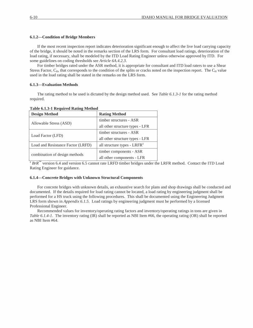
6-10 IDAHO MANUAL FOR BRIDGE EVALUATION
6.1.2—Condition of Bridge Members
If the most recent inspection report indicates deterioration significant enough to affect the live load carrying capacity of the bridge, it should be noted in the remarks section of the LRS form. For consultant load ratings, deterioration of the load rating, if necessary, shall be modeled by the ITD Load Rating Engineer unless otherwise approved by ITD. For some guidelines on coding thresholds see Article 6A.4.2.3.
For timber bridges rated under the ASR method, it is appropriate for consultant and ITD load raters to use a Shear Stress Factor, CH, that corresponds to the condition of the splits or cracks noted on the inspection report. The CH value used in the load rating shall be stated in the remarks on the LRS form.
6.1.3—Evaluation Methods
The rating method to be used is dictated by the design method used. See Table 6.1.3-1 for the rating method required.
Table 6.1.3-1 Required Rating MethodDesign Method Rating Method
Allowable Stress (ASD)timber structures - ASRall other structure types - LFR
Load Factor (LFD)timber structures - ASRall other structure types - LFR
Load and Resistance Factor (LRFD) all structure types - LRFRa
combination of design methodstimber components - ASRall other components - LFR
a BrR™ version 6.4 and version 6.5 cannot rate LRFD timber bridges under the LRFR method. Contact the ITD Load Rating Engineer for guidance.
6.1.4—Concrete Bridges with Unknown Structural Components
For concrete bridges with unknown details, an exhaustive search for plans and shop drawings shall be conducted and documented. If the details required for load rating cannot be located, a load rating by engineering judgment shall be performed for a HS truck using the following procedures. This shall be documented using the Engineering Judgment LRS form shown in Appendix 6.1.5. Load ratings by engineering judgment must be performed by a licensed Professional Engineer.
Recommended values for inventory/operating rating factors and inventory/operating ratings in tons are given in Table 6.1.4-1. The inventory rating (IR) shall be reported as NBI Item #66, the operating rating (OR) shall be reported as NBI Item #64.

SECTION 6: LOAD RATING 6-11
Table 6.1.4-1 Inventory and Operating Ratings by NBI Condition RatingLowest NBI Condition Ratinga Rating Factor Rating in Tonsb
IR OR IRb ORb
9 1.00 1.67 36 608 1.00 1.67 36 607 0.86 1.45 31 526 0.64 1.06 23 385 0.50 0.84 18 304c 0.33 0.56 12 203c 0.17 0.28 6 102c 0.08 0.09 3 3
1 or 0c 0 0 0 0a Choose the lowest NBI Condition Rating for either the #59 (Superstructure), #60 (Substructure), or #62 (Culvert). NBI Item #58 (Deck) does not apply to this policy. b IR and OR are based on the HS-20 truck with a weight (W) of 36 Tons.c Shaded areas where the Condition Rating for the Superstructure, Substructure or Culvert is 4 or less indicate that weight limit posting for State legal loads may be necessary.
Careful consideration should also be given to the specific BrM™ Element Condition States and their corresponding notes in the inspection report. Concrete slabs in Condition State 5 and reinforced concrete and prestressed beams with quantities in Condition State 4 may be considered for lower load rating values.
Coding of the NBI Items in BrM™ shall be as shown in Table 6.1.4-2.
Table 6.1.4-2 BrM™ Inputs for Engineering Judgment RatingsNBI Item # NBI Item Name BrM™ Input
63 Operating Method 0 - Field Eval./Engr. Judgment64 Operating Rating Operating Rating (Tons)65 Inventory Method 0 - Field Eval/Engr. Judgment66 Inventory Rating Inventory Rating (Tons)
RT = RF x W ( 6.1.4-1)RT = Rating in tons for HS truck rounded down the nearest whole tonRF = Rating factor for HS truckW = Weight in tons of HS truck
Load ratings for State legal loads shall not be performed, unless at least one of the NBI Items #58 (Deck), #59 (Superstructure), #60 (Substructure), or # 62 (Culvert) is coded as 4 or less and/or engineering judgment concludes that weight limit posting is required.
A common method used by ITD in establishing weight restrictions for a bridge which is in poor condition (i.e. NBI condition ratings are 4 or less) is to compare the bridge being rated to two similar bridges that have calculated load ratings based on design plans and/or shop drawings. The operating tons for the posting trucks (Idaho Type 3, 3S2 and 3-3) for the EJ bridge rating are derived by multiplying the operating rating tons for the HS-20 as taken from Table 6.1.4-1by the ratio of the operating rating for the posting vehicle for the two similar bridges. The ratings are interpolated basedon this ratio and the span length of the two similar bridges. If possible the bridges used for comparison are constructed around the same time frame as the bridge being rated.

6-12 IDAHO MANUAL FOR BRIDGE EVALUATION
6.1.4.1—Corrugated Metal Pipe and Arches
For corrugated metal pipe and arches with unknown details, an exhaustive search for plans and shop drawings shall be conducted. If plans cannot be located, it usually is possible to field measure the metal pipe and perform a load rating using the Ohio Department of Transportation corrugated metal pipe Excel spreadsheet. If field measurements cannot be obtained or measurements are insufficient to calculate load capacity, a load rating by engineering judgment shall be performed as outlined in Article 6.1.4.
In addition to the live loads listed in Article 6A.2.3.1, all new corrugated structures shall be load rated for a standard gage 120 kip tridem axles (40 kips per axle) with 4.5 foot spacing between axles. This live load can be found on the ITD-modified CMP spreadsheets and the 120 kip tridem load rating results shall be reported on the CMP LRFR LRS.
6.1.4.2—Steel and Timber Bridges
For steel and timber bridges where design plans cannot be located, the rating shall be based on field measurements. Self-weight loads of field-measured structural members shall be increased by ten percent to account for uncertainties in the measured dimensions. If the bridge exhibits severe deterioration or other structural problems the procedures listed in Article 6.1.4 for a load rating by engineering judgment may be performed.
6.1.5—Component-Specific Evaluation
6.1.5.1—Decks
Concrete bridge decks with an NBI rating of 5 or greater need not be evaluated for load capacity, unless bridge has wide spacing between girders or other unusual features. If the deck NBI rating is a 4 or less, consideration should be given to evaluating the bridge deck, if plans are available. For consultant load ratings, the concrete bridge deck rating model shall be done by the ITD Load Rating Engineer unless otherwise approved.
Timber bridge decks and corrugated metal bridge decks shall be evaluated for load capacity using the BrR™software regardless of their condition.
6.1.5.2—Substructures
Substructures are not routinely evaluated; special cases are detailed in the MBE. If the substructure NBI rating is a 4 or less, consideration should be given to evaluating the substructure if plans are available. For consultant load ratings, the substructure rating model shall be done by the ITD Load Rating Engineer unless otherwise approved.
6.1.8—Qualifications and Responsibilities
A registered Professional Engineer licensed in the state of Idaho shall be charged with the overall responsibility for the load rating per Article 6.0.6.
6.1.9—Documentation of Load Rating
The original LRS shall be placed in the appropriate bridge inspection file. A copy of the LRS, the electronic LRS, and supporting calculations shall be placed in the bridge rating files. The BrR™ model shall be maintained in the BrR™database by the ITD Load Rating Engineer. Load rating models utilizing approved software other than BrR™ shall be maintained by the ITD Load Rating Engineer.

SECTION 6: LOAD RATING 6-13
PART A—LOAD AND RESISTANCE FACTOR RATING
6A.1—INTRODUCTION
All new bridges designed under the LRFD code shall be load rated by the LRFR method. Refer to the BDM Article 0.3 and Article 0.4 for submittal procedures on load rating of new bridges and bridge rehabilitation projects and IMBEArticle 6.04 – Required Deliverables for details on the load rating submittal documentation requirements.
Present practice for BAM is to perform evaluations for LRFD bridges using both the LRFR and LFR methods. This is because ITD is currently using LFR to make posting and permitting decisions. For consultant load ratings using the LRFR method, the LFR shall be performed by BAM load rating staff.
6A.1.2—Scope
Part A details procedures for load rating bridges for the LRFD design loading, State legal loads and permit loads. The LRFR shall be consistent with the philosophy and approach of the AASHTO LRFD Bridge Design Specifications and the most current version of the BDM.
6A.1.5—Load and Resistance Factor Rating
For LRFD bridges load rated prior to the inventory bridge inspection, the load rating results for the design vehicle shall be placed on the LRFR Bridge LRS form, an example is shown in Appendix 6.1.1. The legal and permit live load factors, LL, are based on Average Daily Truck Traffic (ADTT). As ADTT will be unknown until the initial bridge inspection, the legal and permit load rating results shall be left blank.
For LRFD bridges already on the State Bridge Inventory, the load rating results shall be placed on the LRFR Bridge LRS found in Appendix 6.1.1 and shall include the design vehicle, legal and permit load rating results. The legal and permit rating results shall be based on the most recent ADTT to determine the appropriate legal and permit live load factors, LL. The ADTT can be calculated based on NBI Items 29 - ADT and 109 – % ADTT.
If no changes to the bridge occur during construction which would affect the initial LRFR design vehicle load rating results, the BAM staff shall complete the legal and permit load ratings in accordance with Article 6.0.2. The bridge designer shall email the ITD Load Rating Engineer stating no changes occurred during construction which would affect the results.
If changes do occur which would affect the rating results, the bridge load rating shall be updated by the bridge designer. If traffic data from the inventory bridge inspection is available at the time of the updated load rating, the updated LRFR Bridge LRS shall include the design vehicle, legal and permit load rating results. The legal and permit rating results shall be based on the most recent ADTT to determine the appropriate legal and permit live load factors, LL.
6A.2—LOADS FOR EVALUATION
6A.2.2—Permanent Loads and Load Factors
6A.2.2.1—Dead Loads: DC and DW
All dead load computations shall be documented in the BrR™ model or supporting calculations. The girder self-weight and composite deck dead loads need not be documented unless providing independent calculations to verify the design load rating (Refer to Article 6.0.6).
The dead loads should be entered into the BrR™ model under separate Load Case Descriptions (i.e. Asphalt, Parapet, Sign Post, etc.). The use of Load Case Descriptions entitled “Composite” or “Non-Composite” is highly discouraged as it is causes problems when updating the model for rehabilitation, repair or other condition changes.
Dead loads to be used in load rating of existing structures shall include the existing loads as noted in the plans and inspection report. Wearing surface dead load shall be based on the thickness of wearing surface noted on the most recent inspection report.
When material unit weights are not listed on the plans, dead load calculations shall be in accordance with Table 3.5.1-1 of the most current edition of the AASHTO LRFD Bridge Design Specifications except as listed in Table 6A.2.2.1-1.
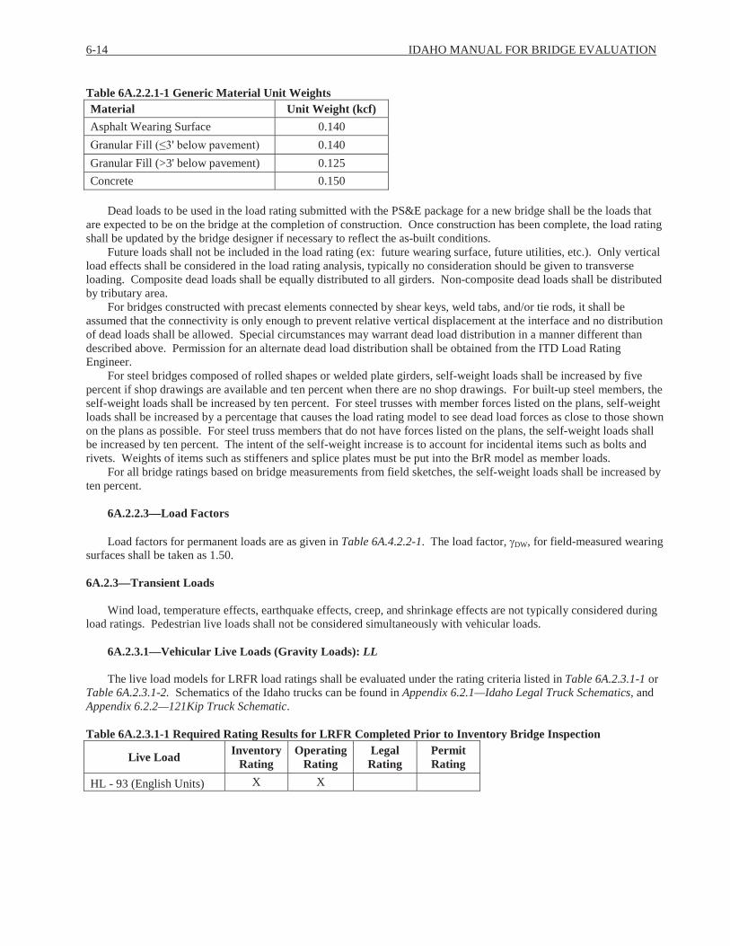
6-14 IDAHO MANUAL FOR BRIDGE EVALUATION
Table 6A.2.2.1-1 Generic Material Unit WeightsMaterial Unit Weight (kcf)Asphalt Wearing Surface 0.140
0.140Granular Fill (>3' below pavement) 0.125Concrete 0.150
Dead loads to be used in the load rating submitted with the PS&E package for a new bridge shall be the loads that are expected to be on the bridge at the completion of construction. Once construction has been complete, the load rating shall be updated by the bridge designer if necessary to reflect the as-built conditions.
Future loads shall not be included in the load rating (ex: future wearing surface, future utilities, etc.). Only vertical load effects shall be considered in the load rating analysis, typically no consideration should be given to transverse loading. Composite dead loads shall be equally distributed to all girders. Non-composite dead loads shall be distributed by tributary area.
For bridges constructed with precast elements connected by shear keys, weld tabs, and/or tie rods, it shall be assumed that the connectivity is only enough to prevent relative vertical displacement at the interface and no distribution of dead loads shall be allowed. Special circumstances may warrant dead load distribution in a manner different than described above. Permission for an alternate dead load distribution shall be obtained from the ITD Load Rating Engineer.
For steel bridges composed of rolled shapes or welded plate girders, self-weight loads shall be increased by five percent if shop drawings are available and ten percent when there are no shop drawings. For built-up steel members, the self-weight loads shall be increased by ten percent. For steel trusses with member forces listed on the plans, self-weight loads shall be increased by a percentage that causes the load rating model to see dead load forces as close to those shown on the plans as possible. For steel truss members that do not have forces listed on the plans, the self-weight loads shall be increased by ten percent. The intent of the self-weight increase is to account for incidental items such as bolts and rivets. Weights of items such as stiffeners and splice plates must be put into the BrR model as member loads.
For all bridge ratings based on bridge measurements from field sketches, the self-weight loads shall be increased by ten percent.
6A.2.2.3—Load Factors
Load factors for permanent loads are as given in Table 6A.4.2.2-1. The load factor, DW, for field-measured wearing surfaces shall be taken as 1.50.
6A.2.3—Transient Loads
Wind load, temperature effects, earthquake effects, creep, and shrinkage effects are not typically considered during load ratings. Pedestrian live loads shall not be considered simultaneously with vehicular loads.
6A.2.3.1—Vehicular Live Loads (Gravity Loads): LL
The live load models for LRFR load ratings shall be evaluated under the rating criteria listed in Table 6A.2.3.1-1 or Table 6A.2.3.1-2. Schematics of the Idaho trucks can be found in Appendix 6.2.1—Idaho Legal Truck Schematics, and Appendix 6.2.2—121Kip Truck Schematic.
Table 6A.2.3.1-1 Required Rating Results for LRFR Completed Prior to Inventory Bridge Inspection
Live Load Inventory Rating
Operating Rating
Legal Rating
Permit Rating
HL - 93 (English Units) X X

SECTION 6: LOAD RATING 6-15
Table 6A.2.3.1-2 Required Rating Results for LRFR Completed After the Inventory Bridge Inspection
Live Load Inventory Rating
Operating Rating
Legal Rating
Permit Rating
HL - 93 (English Units) X XIdaho Type 3 X X
Idaho Type 3S2 X XIdaho Type 3-3 X XIdaho 121 kip X X
NRL Xa Xa
EV2 Xb Xb
EV3 Xb Xb
a If the legal and/or permitrating for the NRL is less than 1.0, the legal and/or permit tonnages for the SU4, SU5, SU6, and SU7 vehicles must be reported on the LRS.b Ratings needed for EV2, EV3 on bridges on interstate and all public bridges within one road mile of an interstate interchange.
6A.2.3.2—Application of Vehicular Live Load
Roadway widths less than 20 feet shall be rated for one lane of traffic.
6A.4—LOAD RATING PROCEDURES
6A.4.1—Introduction
LRFR ratings shall be reported in rating factors and rating tonnages as shown on the LRS in Appendix 6.1.1.
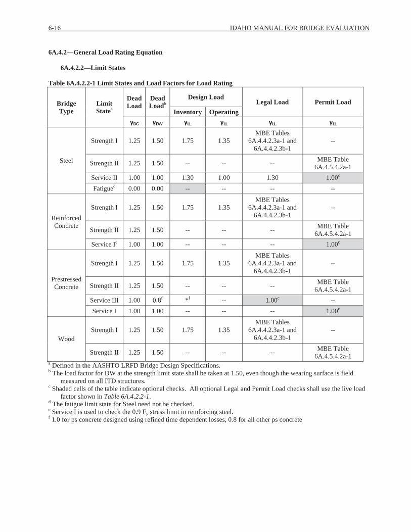
6-16 IDAHO MANUAL FOR BRIDGE EVALUATION
6A.4.2—General Load Rating Equation
6A.4.2.2—Limit States
Table 6A.4.2.2-1 Limit States and Load Factors for Load Rating
Bridge Type
Limit Statea
Dead Load
Dead Loadb
Design LoadLegal Load Permit Load
Inventory Operating
DC DW LL LL LL LL
Steel
Strength I 1.25 1.50 1.75 1.35MBE Tables
6A.4.4.2.3a-1 and 6A.4.4.2.3b-1
--
Strength II 1.25 1.50 -- -- -- MBE Table 6A.4.5.4.2a-1
Service II 1.00 1.00 1.30 1.00 1.30 1.00c
Fatigued 0.00 0.00 -- -- -- --
Reinforced Concrete
Strength I 1.25 1.50 1.75 1.35MBE Tables
6A.4.4.2.3a-1 and 6A.4.4.2.3b-1
--
Strength II 1.25 1.50 -- -- -- MBE Table 6A.4.5.4.2a-1
Service Ie 1.00 1.00 -- -- -- 1.00c
Prestressed Concrete
Strength I 1.25 1.50 1.75 1.35MBE Tables
6A.4.4.2.3a-1 and 6A.4.4.2.3b-1
--
Strength II 1.25 1.50 -- -- -- MBE Table 6A.4.5.4.2a-1
Service III 1.00 0.8f *f -- 1.00c --Service I 1.00 1.00 -- -- -- 1.00c
WoodStrength I 1.25 1.50 1.75 1.35
MBE Tables 6A.4.4.2.3a-1 and
6A.4.4.2.3b-1--
Strength II 1.25 1.50 -- -- -- MBE Table 6A.4.5.4.2a-1
a Defined in the AASHTO LRFD Bridge Design Specifications.b The load factor for DW at the strength limit state shall be taken at 1.50, even though the wearing surface is field
measured on all ITD structures.c Shaded cells of the table indicate optional checks. All optional Legal and Permit Load checks shall use the live load
factor shown in Table 6A.4.2.2-1.d The fatigue limit state for Steel need not be checked.e Service I is used to check the 0.9 Fy stress limit in reinforcing steel.f 1.0 for ps concrete designed using refined time dependent losses, 0.8 for all other ps concrete

SECTION 6: LOAD RATING 6-17
6A.4.2.3—Condition Factor: c
Use c = 1.0 for bridge components that have NBI ratings in accordance with Table 6A.4.2.3-1.
Table 6A.4.2.3-1NBI Coding Thresholds for Use of c = 1.0NBI Item NBI Coding(58) Deck 5 or greater(59) Superstructure 5 or greater(60) Substructure 5 or greater(62) Culvert 6 or greater
The BAM load rating staff may assign a value of c less than 1.0 for a bridge component if the NBI coding is not in accordance with Table 6A.4.2.3-1. Consultant load rating engineers shall use c = 1.0 in the load rating model. If the NBI coding for a bridge is not in accordance with Table 6A.4.2.3-1, a note should be made in the remarks on the LRS form.
6A.5—CONCRETE STRUCTURES
For specifics on the rating models for concrete members, see the following articles: 6.0.7.1 – Prestressed Girders6.0.7.3 – Reinforced Concrete Girders6.0.7.4 – Reinforced Concrete Frames and Box Structures
6A.5.8—Evaluation for Shear
Reinforced concrete and prestressed bridge members shall be evaluated for shear for the design live loads, state legal live loads and permit live loads.
The Shear Computation Method under the LRFR Control Options in the BrR™ model can be set to any method (General Procedure, Simplified Procedure, or Simplified Procedure – Vci, Vcw). It may be preferable to use the same shear computation method in the analysis that was used in the original bridge design calculations.
6A.5.12—Rating of Reinforced Concrete Box Culverts
Refer to Article 6.0.7.4.
6A.6—STEEL STRUCTURES
For specifics on the rating models for steel members, see the following articles:
Article 6.0.7.2 – Steel GirdersArticle 6.0.7.5 – Corrugated Metal Decks and Concrete Filled Grid Decks
6A.8—POSTING OF BRIDGES
Posting decisions are not made based on LRFR. See Article 6B.7 for posting procedures.
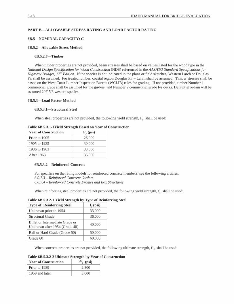
6-18 IDAHO MANUAL FOR BRIDGE EVALUATION
PART B—ALLOWABLE STRESS RATING AND LOAD FACTOR RATING
6B.5—NOMINAL CAPACITY: C
6B.5.2—Allowable Stress Method
6B.5.2.7—Timber
When timber properties are not provided, beam stresses shall be based on values listed for the wood type in the National Design Specification for Wood Construction (NDS) referenced in the AASHTO Standard Specifications for Highway Bridges, 17th Edition. If the species is not indicated in the plans or field sketches, Western Larch or Douglas Fir shall be assumed. For treated lumber, coastal region Douglas Fir – Larch shall be assumed. Timber stresses shall be based on the West Coast Lumber Inspection Bureau (WCLIB) rules for grading. If not provided, timber Number 1 commercial grade shall be assumed for the girders, and Number 2 commercial grade for decks. Default glue-lam will be assumed 20F-V3 western species.
6B.5.3—Load Factor Method
6B.5.3.1—Structural Steel
When steel properties are not provided, the following yield strength, Fy, shall be used:
Table 6B.5.3.1-1Yield Strength Based on Year of ConstructionYear of Construction Fy (psi)Prior to 1905 26,0001905 to 1935 30,0001936 to 1963 33,000After 1963 36,000
6B.5.3.2—Reinforced Concrete
For specifics on the rating models for reinforced concrete members, see the following articles:6.0.7.3 – Reinforced Concrete Girders6.0.7.4 – Reinforced Concrete Frames and Box Structures
When reinforcing steel properties are not provided, the following yield strength, fy, shall be used:
Table 6B.5.3.2-1 Yield Strength by Type of Reinforcing Steel Type of Reinforcing Steel fy (psi)Unknown prior to 1954 33,000Structural Grade 36,000Billet or Intermediate Grade or Unknown after 1954 (Grade 40) 40,000
Rail or Hard Grade (Grade 50) 50,000Grade 60 60,000
When concrete properties are not provided, the following ultimate strength, f’c, shall be used:
Table 6B.5.3.2-2 Ultimate Strength by Year of ConstructionYear of Construction f’c (psi)Prior to 1959 2,5001959 and later 3,000

SECTION 6: LOAD RATING 6-19
6B.5.3.3—Prestressed Concrete
For specifics on the rating models for prestressed concrete members, see Article 6.0.7.1. When prestressed concrete properties are not provided, the following ultimate strength, f’c, shall be used:
Table 6B.5.3.3-1 Ultimate Strength by Year of Construction for Prestressed ConcreteYear of Construction f’c (psi)Prior to 1959 3,0001959 and later 3,500
When the type of prestressing strand is unknown, stress relieved strands should be assumed and the following tensile strength, fpu, shall be used:
Table 6B.5.3.3-2 Tensile Strength by Year of Construction for Prestressed ConcreteYear of Construction fpu (psi)Prior to 1963 2321963 and later 250
6B.6—LOADINGS
Wind load, temperature effects, earthquake effects, creep, and shrinkage effects are typically not considered during load ratings. Pedestrian live loads shall not be considered simultaneously with vehicular loads.
6B.6.1—Dead Load: D
The provisions of Article 6A.2.2.1 shall apply for Load Factor and Allowable Stress Ratings.
6B.6.2—Rating Live Load
The live load models for LFR and ASR load ratings shall be evaluated under the rating criteria listed in Table 6B.6.2-1. Schematics of the Idaho trucks can be found in Appendix 6.2.1 (Idaho Type 3, 3S2, and 3-3) and Appendix 6.2.2 (121Kip truck).
Table 6B.6.2-1 Required Rating Results for ASR and LFRLive Load Inventory Rating Operating RatingDesign Truck Shown on Plansa X XHS-20 X XIdaho Type 3 X XIdaho Type 3S2 X XIdaho Type 3-3 X XIdaho 121 kip X XNRL X Xb
EV2 Xc Xc
EV3 Xc Xc
a If the design truck shown on the plans is the HS-20, this line shall be left blank on the LRS form.b If the operating rating for the NRL is less than 1.0, operating tonnages for the SU4, SU5, SU6, and SU7 vehicles must
be reported on the LRS.c Ratings needed for EV2, EV3 on bridges on interstate and all public bridges within one road mile of an interstate interchange.
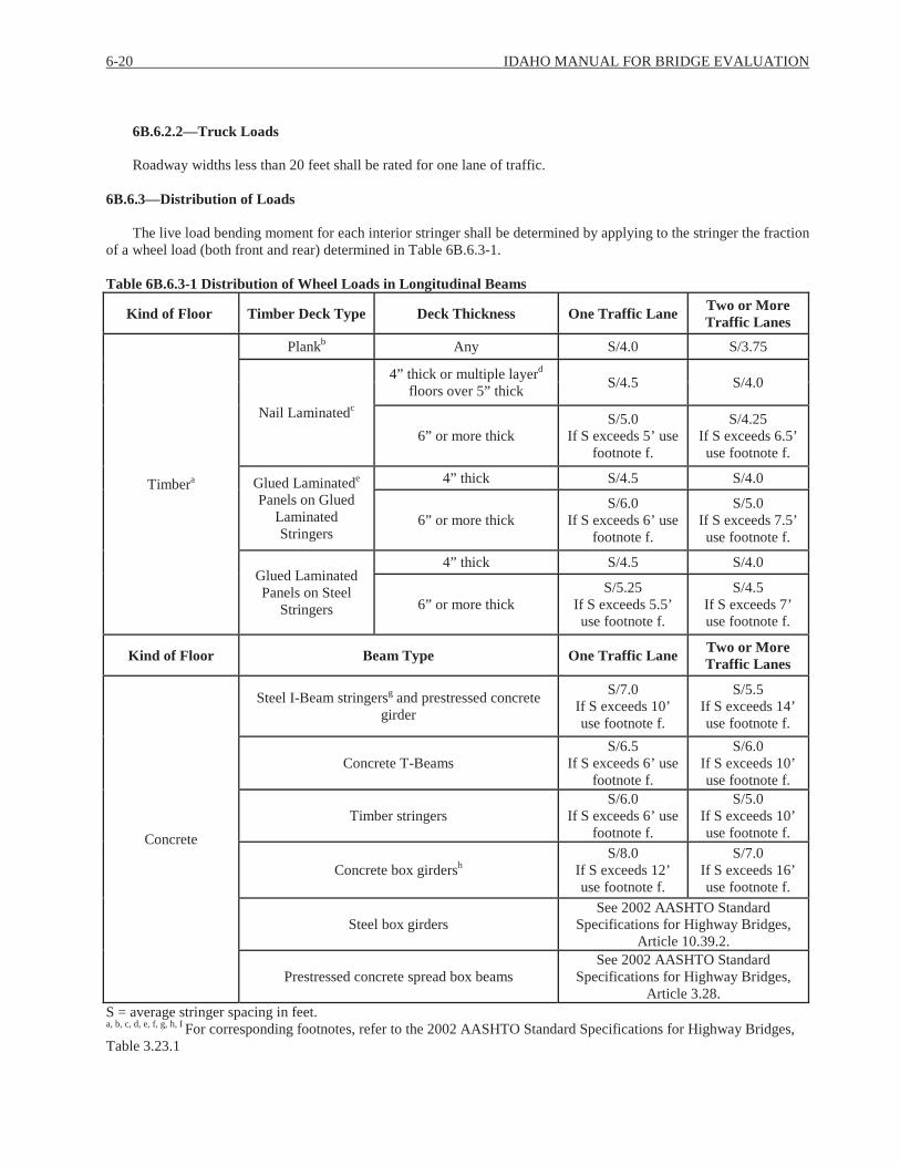
6-20 IDAHO MANUAL FOR BRIDGE EVALUATION
6B.6.2.2—Truck Loads
Roadway widths less than 20 feet shall be rated for one lane of traffic.
6B.6.3—Distribution of Loads
The live load bending moment for each interior stringer shall be determined by applying to the stringer the fraction of a wheel load (both front and rear) determined in Table 6B.6.3-1.
Table 6B.6.3-1 Distribution of Wheel Loads in Longitudinal Beams
Kind of Floor Timber Deck Type Deck Thickness One Traffic Lane Two or More Traffic Lanes
Timbera
Plankb Any S/4.0 S/3.75
Nail Laminatedc
4” thick or multiple layerd
floors over 5” thick S/4.5 S/4.0
6” or more thickS/5.0
If S exceeds 5’ use footnote f.
S/4.25 If S exceeds 6.5’ use footnote f.
Glued Laminatede
Panels on Glued Laminated Stringers
4” thick S/4.5 S/4.0
6” or more thickS/6.0
If S exceeds 6’ use footnote f.
S/5.0 If S exceeds 7.5’ use footnote f.
Glued Laminated Panels on Steel
Stringers
4” thick S/4.5 S/4.0
6” or more thickS/5.25
If S exceeds 5.5’ use footnote f.
S/4.5 If S exceeds 7’ use footnote f.
Kind of Floor Beam Type One Traffic Lane Two or More Traffic Lanes
Concrete
Steel I-Beam stringersg and prestressed concrete girder
S/7.0 If S exceeds 10’ use footnote f.
S/5.5 If S exceeds 14’ use footnote f.
Concrete T-BeamsS/6.5
If S exceeds 6’ use footnote f.
S/6.0 If S exceeds 10’ use footnote f.
Timber stringersS/6.0
If S exceeds 6’ use footnote f.
S/5.0 If S exceeds 10’ use footnote f.
Concrete box girdershS/8.0
If S exceeds 12’ use footnote f.
S/7.0 If S exceeds 16’ use footnote f.
Steel box girdersSee 2002 AASHTO Standard
Specifications for Highway Bridges, Article 10.39.2.
Prestressed concrete spread box beamsSee 2002 AASHTO Standard
Specifications for Highway Bridges, Article 3.28.
S = average stringer spacing in feet.a, b, c, d, e, f, g, h, I For corresponding footnotes, refer to the 2002 AASHTO Standard Specifications for Highway Bridges, Table 3.23.1

SECTION 6: LOAD RATING 6-21
Table 6B.6.3-1 (Continued) Distribution of Wheel Loads in Longitudinal Beams
Kind of Floor Deck Thickness One Traffic Lane Two or More Traffic Lanes
Steel Grid
Less than 4” thick S/4.5 S/4.0
4” or more thickS/6.0
If S exceeds 6’ usefootnote f.
S/5.0 If S exceeds
10.5’ use footnote f.
Kind of Floor Corrugation Depth One Traffic Lane Two or More Traffic Lanes
Steel bridge corrugated planki 2” min. depth S/5.5 S/4.5
S = average stringer spacing in feet.a, b, c, d, e, f, g, h, I For corresponding footnotes, refer to the 2002 AASHTO Standard Specifications for Highway Bridges, Table 3.23.1
6B.7—POSTING OF BRIDGES
6B.7.1—General
If load rating calculations indicate that any of the State legal loads or SHV loads has an operating rating factor less than 1.0, then the bridge must be load posted for weight restrictions. For a schematic of the Idaho Load Posting trucks see Appendix 6.2.1.
ITD and consultant load raters shall routinely load rate state and local government structures and develop recommendations for weight restrictions. Recommendations are to be submitted to the BAME and entered into a database containing all bridge inspection information for each structure (BrM™). Recommended postings shall be compared with actual postings to verify whether the structure is properly posted for weight restrictions. If a structure is not properly posted, the procedures outlined in Articles 6B.7.1.1 and 6B.7.1.2 shall be used.
Bridges not capable of carrying a minimum gross live load weight of three tons at the operating level must be closed.
The authority and responsibility of Bridge Owners to post or restrict bridges is outlined in the following regulations:
Idaho Statute 40-619
Idaho Statute 40-1206
Idaho Statute 10-1207
23 CFR 650.307
23 CFR 650.313
In situations where a local Bridge Owner does not post or close a bridge in accordance with the policies outlined in the IMBE, ITD may have to take actions to ensure the public’s safety on locally owned highway bridges.
6B.7.1.1—Posting and Closure Procedures of ITD Maintained Structures
When an ITD structure requires closure or load restrictions, and signage and/or barricades are not yet installed or properly installed, the following procedure shall be followed:
1. Notification—The District Engineer and Maintenance Engineer are notified of the posting or closure requirements via phone call or e-mail from the BAME or designee. As a follow-up, a letter prepared by the BAM Engineer is sent
6-22 IDAHO MANUAL FOR BRIDGE EVALUATION
to the District detailing required actions. If load posting is required, the letter shall also contain schematics of the required signs.
2. Action—The District Engineer shall be required to perform the necessary actions to properly load post or close the structure. Bridge closure shall occur within 2 days of notification and load posting shall occur within 10 days. Arepresentative from the District is required to contact the BAME when the posting signs or barricades have been installed. Once BAM is notified that the proper signs and/or barricades have been installed, the BrM™ database shall be updated to reflect the actual posting tonnages or closure.
3. Follow Up—If BAM is not notified of compliance within the required timeframes, the District shall be contacted again by either e-mail or phone. The bridge shall be added to the Critical Deficiency Tracking System and continue to be monitored in accordance with Article 4.8.1.4.4. The bridge inspector confirms signs are in place and correct at all routine bridge inspections.
6B.7.1.2—Posting and Closure Procedures of Locally Owned Structures
When a locally owned structure requires closure or load restrictions, and signage and/or barricades are not yet installed or properly installed, the following procedures shall be followed:
1. Notification— The local agency shall be notified via phone call or email from the BAM Engineer or designee if closure is required. A letter prepared by the BAME shall be sent to the local agency detailing required actions. If load posting is required, the letter shall also contain schematics of the required signs.
2. Action—The local agency shall be required to perform the necessary actions to properly post or close the structure.Bridge closure shall occur within 5 days of notification and posting within 30 days. Certain unforeseen circumstances such as weather-related events may legitimately preclude the local agency from meeting these timelines. In that case the BAM and local agency shall agree to a reasonable date for the posting or closure. The local agency is required to contact the BAME when the posting signs or barricades have been installed.
3. Follow Up—If the local agency fails to notify BAM within the timeframes identified above, a follow-up letter shall be sent by the BAME. At this point the bridge shall be added to the Critical Deficiency Tracking System and shall continue to be monitored in accordance with Article 4.8.1.4.5. If the local agency fails to notify BAM within 5 business days that corrective action has been taken, a second follow-up letter shall be sent by the Chief Engineer or designee. This letter shall inform the local agency that Federal and State funds may be suspended until appropriate corrective actions are taken. The FHWA Division Administrator and LHTAC shall be copied on the letter in addition to appropriate ITD personnel. Additionally, the appropriate ITD District Engineer shall be contacted and either he/she or designee shall follow-up with local highway agency personnel and offer assistance to get the bridge properly posted or closed.
Once BAM is notified that the proper signs and/or barricades have been installed, the BrM™ database shall be updated to reflect the actual posting tonnages or closure. The bridge inspector confirms proper signs are in place and correct at all routine bridge inspections.
6B.7.1.3—Emergency Posting of Weight Restrictions on Structures
In case of bona fide emergencies, the District Engineer or designee shall take the necessary steps to protect the public safety. Examples of emergencies are collision, flood, or fire damage.
Corrective action may be required prior to a complete evaluation by BAM or Bridge Design. Such action may consist of restricting the traffic to certain lanes or posting the structure for no trucks, or only trucks below a specified gross weight.
The offices of Ports of Entry, Motor Carrier, and over legal permits should immediately be verbally notified with a follow-up notification in writing of any temporary restrictions on the State Highway system as well as the time the restrictions are lifted or modified.
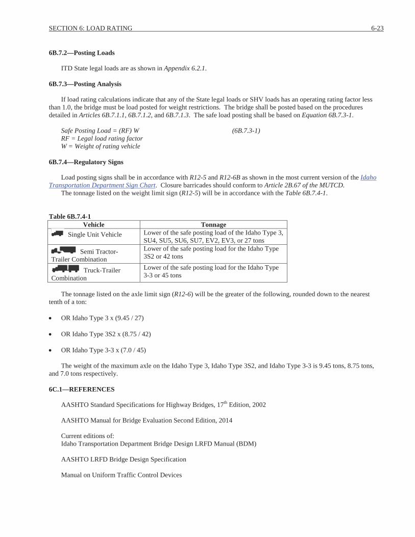
SECTION 6: LOAD RATING 6-23
6B.7.2—Posting Loads
ITD State legal loads are as shown in Appendix 6.2.1.
6B.7.3—Posting Analysis
If load rating calculations indicate that any of the State legal loads or SHV loads has an operating rating factor less than 1.0, the bridge must be load posted for weight restrictions. The bridge shall be posted based on the procedures detailed in Articles 6B.7.1.1, 6B.7.1.2, and 6B.7.1.3. The safe load posting shall be based on Equation 6B.7.3-1.
Safe Posting Load = (RF) W (6B.7.3-1)RF = Legal load rating factorW = Weight of rating vehicle
6B.7.4—Regulatory Signs
Load posting signs shall be in accordance with R12-5 and R12-6B as shown in the most current version of the Idaho Transportation Department Sign Chart. Closure barricades should conform to Article 2B.67 of the MUTCD.
The tonnage listed on the weight limit sign (R12-5) will be in accordance with the Table 6B.7.4-1.
Table 6B.7.4-1Vehicle Tonnage
Single Unit Vehicle Lower of the safe posting load of the Idaho Type 3, SU4, SU5, SU6, SU7, EV2, EV3, or 27 tons
Semi Tractor-Trailer Combination
Lower of the safe posting load for the Idaho Type 3S2 or 42 tons
Truck-Trailer Combination
Lower of the safe posting load for the Idaho Type 3-3 or 45 tons
The tonnage listed on the axle limit sign (R12-6) will be the greater of the following, rounded down to the nearest tenth of a ton:
OR Idaho Type 3 x (9.45 / 27)
OR Idaho Type 3S2 x (8.75 / 42)
OR Idaho Type 3-3 x (7.0 / 45)
The weight of the maximum axle on the Idaho Type 3, Idaho Type 3S2, and Idaho Type 3-3 is 9.45 tons, 8.75 tons, and 7.0 tons respectively.
6C.1—REFERENCES
AASHTO Standard Specifications for Highway Bridges, 17th Edition, 2002
AASHTO Manual for Bridge Evaluation Second Edition, 2014
Current editions of:Idaho Transportation Department Bridge Design LRFD Manual (BDM)
AASHTO LRFD Bridge Design Specification
Manual on Uniform Traffic Control Devices

PAGE INTENTIONALLY LEFT BLANK
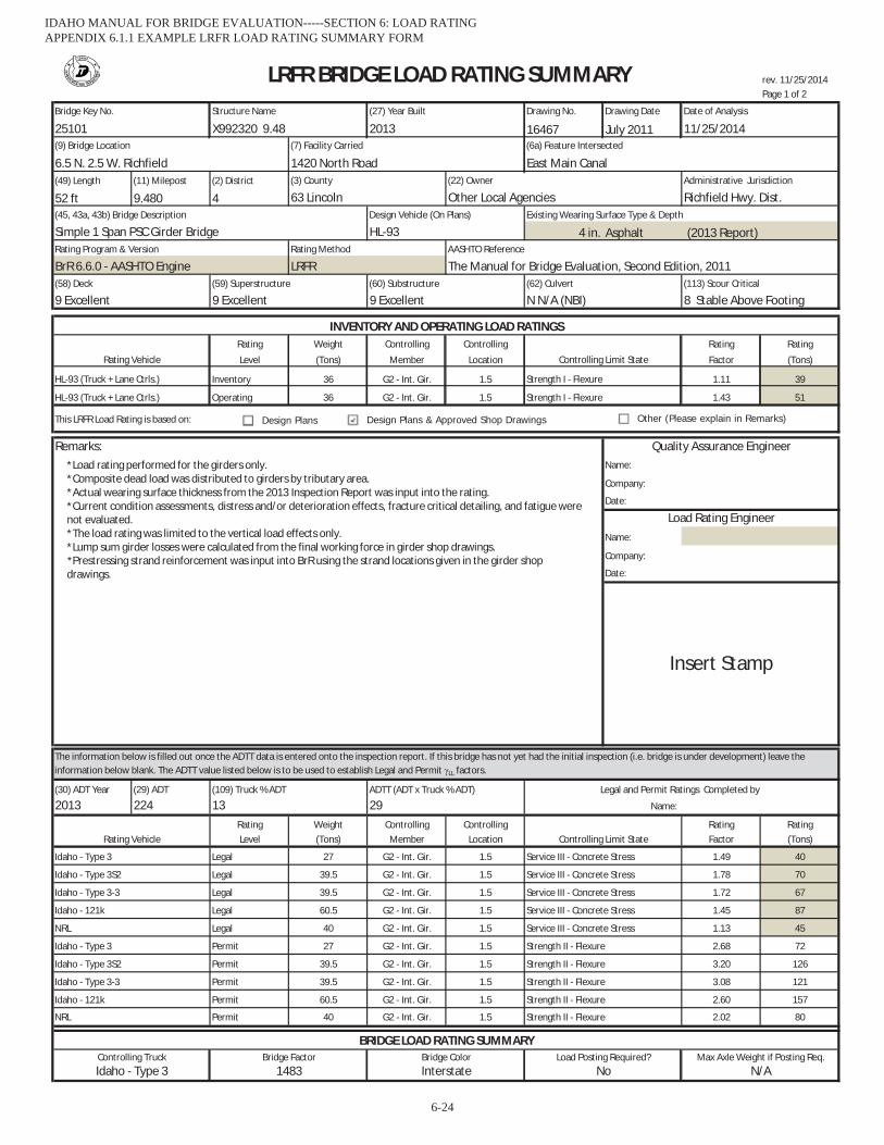
rev. 11/25/2014Page 1 of 2
Drawing No. Drawing Date
16467 July 2011
(49) Length (11) Milepost (2) District
52 ft 9.480 4
4 in. Asphalt (2013 Report)
Rating Weight Controlling Controlling Rating Rating
Level (Tons) Member Location Factor (Tons)
Inventory 36 G2 - Int. Gir. 1.5 1.11 39
Operating 36 G2 - Int. Gir. 1.5 1.43 51
This LRFR Load Rating is based on:
Remarks:Name:
Company:
Date:
Name:
Company:
Date:
(30) ADT Year (29) ADT
2013 224Rating Weight Controlling Controlling Rating RatingLevel (Tons) Member Location Factor (Tons)
Legal 27 G2 - Int. Gir. 1.5 1.49 40
Legal 39.5 G2 - Int. Gir. 1.5 1.78 70
Legal 39.5 G2 - Int. Gir. 1.5 1.72 67
Legal 60.5 G2 - Int. Gir. 1.5 1.45 87
Legal 40 G2 - Int. Gir. 1.5 1.13 45
Permit 27 G2 - Int. Gir. 1.5 2.68 72
Permit 39.5 G2 - Int. Gir. 1.5 3.20 126
Permit 39.5 G2 - Int. Gir. 1.5 3.08 121
Permit 60.5 G2 - Int. Gir. 1.5 2.60 157
Permit 40 G2 - Int. Gir. 1.5 2.02 80
N/AControlling Truck Bridge Factor Load Posting Required? Max Axle Weight if Posting Req.Bridge Color
BRIDGE LOAD RATING SUMMARY
Idaho - Type 3
Idaho - Type 3S2
NRL
The information below is filled out once the ADTT data is entered onto the inspection report. If this bridge has not yet had the initial inspection (i.e. bridge is under development) leave the information below blank. The ADTT value listed below is to be used to establish Legal and Permit LL factors.
Idaho - Type 3-3
Idaho - Type 3S2
Rating Vehicle Controlling Limit State
(109) Truck % ADT ADTT (ADT x Truck % ADT)
13 29 Name:
Legal and Permit Ratings Completed by
Idaho - 121k
Idaho - Type 3 1483 Interstate No
Idaho - Type 3
Idaho - Type 3-3
Strength II - Flexure
Service III - Concrete Stress
Strength II - Flexure
Service III - Concrete Stress
Strength II - Flexure
Service III - Concrete Stress
Service III - Concrete Stress
Strength II - Flexure
Service III - Concrete Stress
Strength II - Flexure
Idaho - 121k
NRL
(9) Bridge Location (7) Facility Carried (6a) Feature Intersected
6.5 N. 2.5 W. Richfield
Simple 1 Span PSC Girder Bridge HL-93Existing Wearing Surface Type & Depth
1420 North Road East Main Canal
(45, 43a, 43b) Bridge Description Design Vehicle (On Plans)
(3) County
63 Lincoln(22) Owner
Other Local Agencies Richfield Hwy. Dist.Administrative Jurisdiction
AASHTO Reference
BrR 6.6.0 - AASHTO Engine(58) Deck (59) Superstructure (62) Culvert (113) Scour Critical
9 Excellent 9 Excellent 9 Excellent N N/A (NBI)
The Manual for Bridge Evaluation, Second Edition, 2011LRFRRating Program & Version Rating Method
LRFR BRIDGE LOAD RATING SUMMARY
25101 X992320 9.48 2013 11/25/2014Bridge Key No. Structure Name Date of Analysis(27) Year Built
Strength I - Flexure
8 Stable Above Footing
Quality Assurance Engineer
Load Rating Engineer
(60) Substructure
INVENTORY AND OPERATING LOAD RATINGS
Controlling Limit State
Strength I - Flexure
Insert Stamp
Rating Vehicle
HL-93 (Truck + Lane Ctrls.)
HL-93 (Truck + Lane Ctrls.)
*Load rating performed for the girders only. *Composite dead load was distributed to girders by tributary area. *Actual wearing surface thickness from the 2013 Inspection Report was input into the rating. *Current condition assessments, distress and/or deterioration effects, fracture critical detailing, and fatigue were not evaluated. *The load rating was limited to the vertical load effects only. *Lump sum girder losses were calculated from the final working force in girder shop drawings. *Prestressing strand reinforcement was input into BrR using the strand locations given in the girder shop drawings.
Design Plans & Approved Shop DrawingsDesign Plans Other (Please explain in Remarks)
IDAHO MANUAL FOR BRIDGE EVALUATION-----SECTION 6: LOAD RATING APPENDIX 6.1.1 EXAMPLE LRFR LOAD RATING SUMMARY FORM
6-24
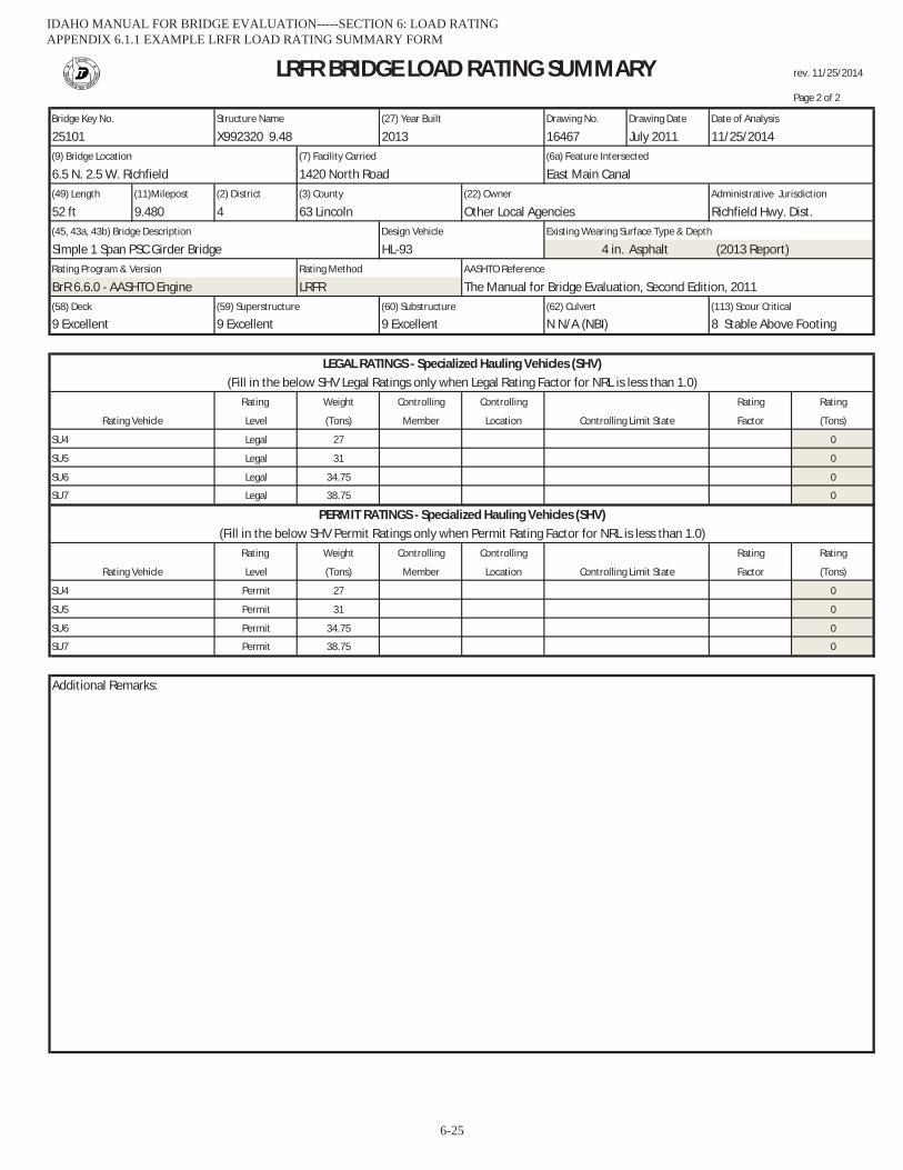
rev. 11/25/2014
Page 2 of 2
Drawing No. Drawing Date
16467 July 2011
(49) Length (11)Milepost (2) District
52 ft 9.480 4
4 in. Asphalt (2013 Report)
Rating Weight Controlling Controlling Rating Rating
Level (Tons) Member Location Factor (Tons)
Legal 27 0
Legal 31 0
Legal 34.75 0
Legal 38.75 0
Rating Weight Controlling Controlling Rating Rating
Level (Tons) Member Location Factor (Tons)
Permit 27 0
Permit 31 0
Permit 34.75 0
Permit 38.75 0
Additional Remarks:
HL-93Rating Program & Version Rating Method AASHTO Reference
BrR 6.6.0 - AASHTO Engine LRFR The Manual for Bridge Evaluation, Second Edition, 2011
Simple 1 Span PSC Girder Bridge
63 Lincoln Other Local Agencies Richfield Hwy. Dist.(45, 43a, 43b) Bridge Description Design Vehicle Existing Wearing Surface Type & Depth
East Main Canal
LRFR BRIDGE LOAD RATING SUMMARY
(3) County (22) Owner Administrative Jurisdiction
Bridge Key No. Structure Name (27) Year Built Date of Analysis
25101 X992320 9.48 2013 11/25/2014
(60) Substructure (113) Scour Critical
Rating Vehicle
(9) Bridge Location (7) Facility Carried (6a) Feature Intersected
Controlling Limit State
6.5 N. 2.5 W. Richfield 1420 North Road
(58) Deck (62) Culvert
LEGAL RATINGS - Specialized Hauling Vehicles (SHV)
(59) Superstructure
(Fill in the below SHV Legal Ratings only when Legal Rating Factor for NRL is less than 1.0)
8 Stable Above Footing
SU6
SU7
SU5
SU4
9 Excellent 9 Excellent 9 Excellent N N/A (NBI)
SU6
SU7
PERMIT RATINGS - Specialized Hauling Vehicles (SHV)(Fill in the below SHV Permit Ratings only when Permit Rating Factor for NRL is less than 1.0)
Rating Vehicle Controlling Limit State
SU4
SU5
IDAHO MANUAL FOR BRIDGE EVALUATION-----SECTION 6: LOAD RATING APPENDIX 6.1.1 EXAMPLE LRFR LOAD RATING SUMMARY FORM
6-25
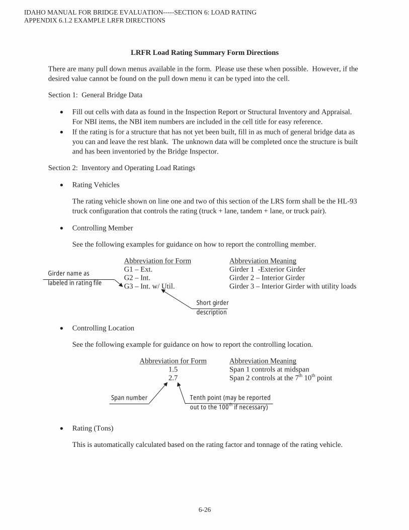
LRFR Load Rating Summary Form Directions
There are many pull down menus available in the form. Please use these when possible. However, if the desired value cannot be found on the pull down menu it can be typed into the cell.
Section 1: General Bridge Data
Fill out cells with data as found in the Inspection Report or Structural Inventory and Appraisal. For NBI items, the NBI item numbers are included in the cell title for easy reference.If the rating is for a structure that has not yet been built, fill in as much of general bridge data as you can and leave the rest blank. The unknown data will be completed once the structure is built and has been inventoried by the Bridge Inspector.
Section 2: Inventory and Operating Load Ratings
Rating Vehicles
The rating vehicle shown on line one and two of this section of the LRS form shall be the HL-93 truck configuration that controls the rating (truck + lane, tandem + lane, or truck pair).
Controlling Member
See the following examples for guidance on how to report the controlling member.
Abbreviation for Form Abbreviation MeaningG1 – Ext. Girder 1 -Exterior GirderG2 – Int. Girder 2 – Interior GirderG3 – Int. w/ Util. Girder 3 – Interior Girder with utility loads
Controlling Location
See the following example for guidance on how to report the controlling location.
Abbreviation for Form Abbreviation Meaning1.5 Span 1 controls at midspan2.7 Span 2 controls at the 7th 10th point
Rating (Tons)
This is automatically calculated based on the rating factor and tonnage of the rating vehicle.
Girder name as labeled in rating file
Short girder description
Span number Tenth point (may be reported out to the 100th if necessary)
IDAHO MANUAL FOR BRIDGE EVALUATION-----SECTION 6: LOAD RATING APPENDIX 6.1.2 EXAMPLE LRFR DIRECTIONS
6-26
Load Rating Basis
Please indicate if the load rating is based on Design Plans, Design Plans and Approved Shop Drawings or Other. When “Other” is used, provide an explanation in the remarks (e.g., Approved Shop Drawings only, or Field Measurements).
Section 3: Remarks and Signature
There is a text box under remarks. Please fill this in with any assumptions that were made for the load rating. If needed, the bottom of page 2 of the LRS has extra room for additional remarks. Please fill in the information for the people that worked on the load rating. Please have a Professional Engineer licensed in the State of Idaho stamp the final copy. For load ratings completed prior to the inventory inspection, the stamp will only apply to the HL-93 ratings.
Section 4: Legal, Permit, and Emergency Vehicle (EV) Ratings
Fill in the traffic data per the inspection report. The ADTT shown on this form shall also be used to compute the Legal and Permit Live Load Factors ( LL) used in the load rating model. If the bridge has not had the inventory inspection, the Legal and Permit Ratings shall be left blank. Once the inventory inspection is completed, the Legal and Permit Ratings shall be completed. If there were design changes during construction requiring modifications to the load rating, the Legal and Permit Ratings shall be completed by the original Load Rater. If there were no changes during construction, ITD staff will complete the Legal and Permit Ratings. The Legal and Permit rating vehicles shall be as shown on the LRS form.If the Legal and/or Permit Rating Factor for the NRL truck is less than 1.0, refer to Section 7: Legal and Permit Ratings for Specialized Hauling Vehicle (SHV). Emergency vehicle rating (when applicable) Type EV2 & EV3 shall be reported as legal rating factor in the remarks.
Section 5: Bridge Load Rating Summary
All of the fields in this section are automatically calculated based on the ratings input in Section 4. These fields are related to ITD’s over legal weight permit vehicle screening process and ITD’s Route Capacity Map.
Section 6: General Bridge Data
The General Bridge Data on page 2 of the LRS will automatically be populated once the General Bridge Data on page 1 is completed.
Section 7: Legal and Permit Ratings for Specialized Hauling Vehicle (SHV)
If the Legal Rating Factor for the NRL truck is less than 1.0, the Legal Ratings for the four SHV trucks (SU4, SU5, SU6, and SU7) on page 2 of the LRS must be completed. If the Legal Rating Factor for the NRL truck is 1.0 or above, leave the Legal Ratings for the SHV blank.
IDAHO MANUAL FOR BRIDGE EVALUATION-----SECTION 6: LOAD RATING APPENDIX 6.1.2 EXAMPLE LRFR DIRECTIONS
6-27

If the Permit Rating Factor for the NRL truck is less than 1.0, the Permit Ratings for the four SHV trucks on page 2 of the LRS must be completed. If the Permit Rating Factor for the NRL is 1.0 or above, leave Permit Ratings for the SHV blank.
IDAHO MANUAL FOR BRIDGE EVALUATION-----SECTION 6: LOAD RATING APPENDIX 6.1.2 EXAMPLE LRFR DIRECTIONS
6-28
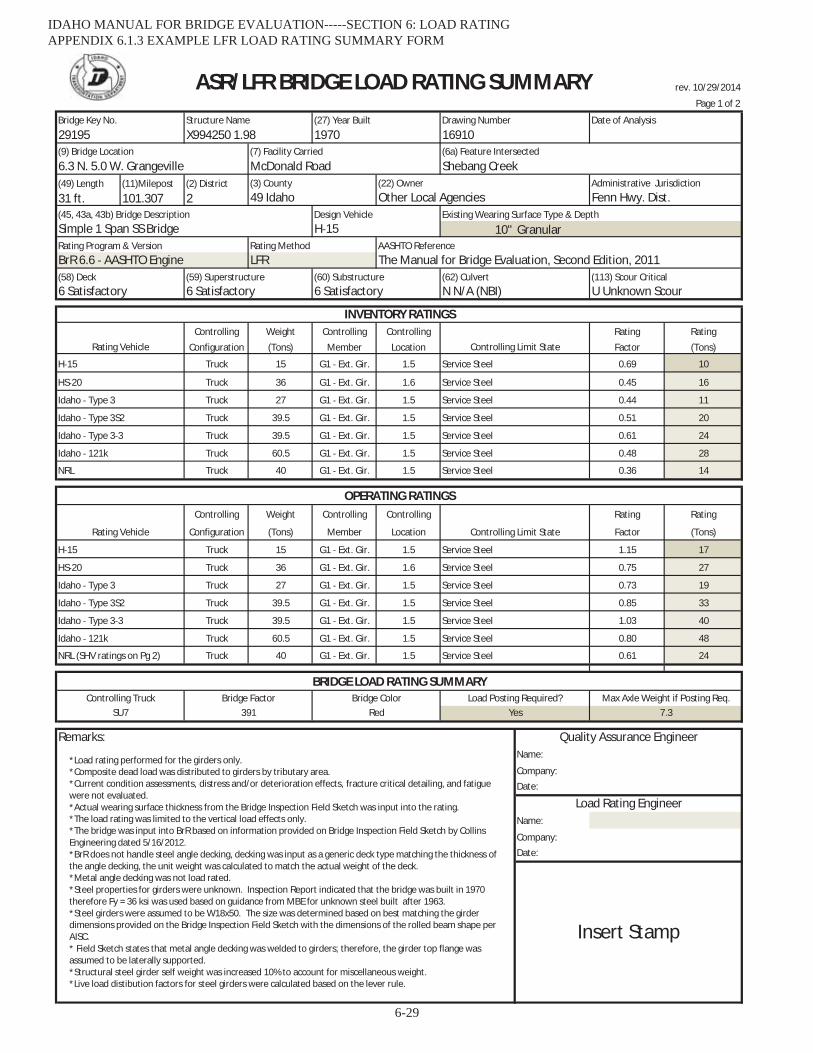
rev. 10/29/2014
Page 1 of 2
(49) Length (11)Milepost (2) District31 ft. 101.307 2
10" Granular
Controlling Weight Controlling Controlling Rating RatingConfiguration (Tons) Member Location Factor (Tons)
Truck 15 G1 Ext. Gir. 1.5 0.69 10
Truck 36 G1 Ext. Gir. 1.6 0.45 16
Truck 27 G1 Ext. Gir. 1.5 0.44 11
Truck 39.5 G1 Ext. Gir. 1.5 0.51 20
Truck 39.5 G1 Ext. Gir. 1.5 0.61 24
Truck 60.5 G1 Ext. Gir. 1.5 0.48 28
Truck 40 G1 Ext. Gir. 1.5 0.36 14
Controlling Weight Controlling Controlling Rating Rating
Configuration (Tons) Member Location Factor (Tons)
Truck 15 G1 Ext. Gir. 1.5 1.15 17
Truck 36 G1 Ext. Gir. 1.6 0.75 27
Truck 27 G1 Ext. Gir. 1.5 0.73 19
Truck 39.5 G1 Ext. Gir. 1.5 0.85 33
Truck 39.5 G1 Ext. Gir. 1.5 1.03 40
Truck 60.5 G1 Ext. Gir. 1.5 0.80 48
Truck 40 G1 Ext. Gir. 1.5 0.61 24
Remarks:Name:
Company:Date:
Name:
Company:Date:
(9) Bridge Location (7) Facility Carried (6a) Feature Intersected
ASR/LFR BRIDGE LOAD RATING SUMMARY
29195 X994250 1.98 1970 16910Bridge Key No. Structure Name Date of AnalysisDrawing Number(27) Year Built
(62) CulvertN N/A (NBI)
BrR 6.6 AASHTO EngineRating Program & Version
(113) Scour CriticalU Unknown Scour
(58) Deck (59) Superstructure (60) Substructure6 Satisfactory 6 Satisfactory 6 Satisfactory
6.3 N. 5.0 W. Grangeville McDonald Road Shebang Creek
The Manual for Bridge Evaluation, Second Edition, 2011LFR
(45, 43a, 43b) Bridge Description Design VehicleSimple 1 Span SS Bridge H 15
Existing Wearing Surface Type & Depth
(22) OwnerOther Local Agencies Fenn Hwy. Dist.
Administrative Jurisdiction
AASHTO Reference
(3) County49 Idaho
Rating Method
INVENTORY RATINGS
Service Steel
Service Steel
H 15
Controlling Limit State
Service Steel
Idaho Type 3
Idaho Type 3 3
Idaho 121k
Rating Vehicle
Service Steel
Idaho Type 3S2
Service Steel
HS 20 Service Steel
NRL Service Steel
Controlling Limit State
Service Steel
OPERATING RATINGS
Rating Vehicle
Idaho Type 3S2 Service Steel
Idaho Type 3 3 Service Steel
Idaho Type 3 Service Steel
H 15
HS 20 Service Steel
Quality Assurance Engineer
Service Steel
Yes
BRIDGE LOAD RATING SUMMARYControlling Truck Bridge Factor Load Posting Required? Max Axle Weight if Posting Req.
SU7 391 Red 7.3
Load Rating Engineer
Insert Stamp
Idaho 121k
NRL (SHV ratings on Pg 2) Service Steel
Bridge Color
*Load rating performed for the girders only.*Composite dead load was distributed to girders by tributary area.*Current condition assessments, distress and/or deterioration effects, fracture critical detailing, and fatiguewere not evaluated.*Actual wearing surface thickness from the Bridge Inspection Field Sketch was input into the rating.*The load rating was limited to the vertical load effects only.*The bridge was input into BrR based on information provided on Bridge Inspection Field Sketch by CollinsEngineering dated 5/16/2012.*BrR does not handle steel angle decking, decking was input as a generic deck type matching the thickness ofthe angle decking, the unit weight was calculated to match the actual weight of the deck.*Metal angle decking was not load rated.*Steel properties for girders were unknown. Inspection Report indicated that the bridge was built in 1970therefore Fy = 36 ksi was used based on guidance from MBE for unknown steel built after 1963.*Steel girders were assumed to be W18x50. The size was determined based on best matching the girderdimensions provided on the Bridge Inspection Field Sketch with the dimensions of the rolled beam shape perAISC.* Field Sketch states that metal angle decking was welded to girders; therefore, the girder top flange wasassumed to be laterally supported.*Structural steel girder self weight was increased 10% to account for miscellaneous weight.*Live load distibution factors for steel girders were calculated based on the lever rule.
IDAHO MANUAL FOR BRIDGE EVALUATION-----SECTION 6: LOAD RATING APPENDIX 6.1.3 EXAMPLE LFR LOAD RATING SUMMARY FORM
6-29
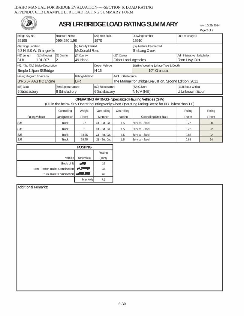
rev. 10/29/2014
Page 2 of 2
(49) Length (11)Milepost (2) District31 ft. 101.307 2
10" Granular
Controlling Weight Controlling Controlling Rating Rating
Configuration (Tons) Member Location Factor (Tons)
Truck 27 G1 Ext. Gir. 1.5 0.77 20
Truck 31 G1 Ext. Gir. 1.5 0.72 22
Truck 34.75 G1 Ext. Gir. 1.5 0.65 22Truck 38.75 G1 Ext. Gir. 1.5 0.63 24
Posting
Vehicle Schematic (Tons)
19
33
40
Max Axle 7.3
Additional Remarks:
(9) Bridge Location (7) Facility Carried (6a) Feature Intersected6.3 N. 5.0 W. Grangeville McDonald Road Shebang Creek
(3) County (22) Owner Administrative Jurisdiction
BrR 6.6 AASHTO Engine LFR The Manual for Bridge Evaluation, Second Edition, 2011(59) Superstructure (60) Substructure (113) Scour Critical
6 Satisfactory 6 Satisfactory 6 Satisfactory N N/A (NBI) U Unknown Scour(58) Deck (62) Culvert
49 Idaho Other Local Agencies Fenn Hwy. Dist.(45, 43a, 43b) Bridge Description Design Vehicle Existing Wearing Surface Type & Depth
Simple 1 Span SS Bridge H 15Rating Program & Version Rating Method AASHTO Reference
(Fill in the below SHV OperatingRatings only when Operating Rating Factor for NRL is less than 1.0)
Single Unit
Semi Tractor Trailer Combination
Truck Trailer Combination
POSTING
Service Steel
ASR/LFR BRIDGE LOAD RATING SUMMARY
SU6 Service Steel
SU7 Service Steel
OPERATING RATINGS Specialized Hauling Vehicles (SHV)
Bridge Key No. Structure Name (27) Year Built Drawing Number Date of Analysis
29195 X994250 1.98 1970 16910
Rating Vehicle Controlling Limit State
SU4 Service Steel
SU5
IDAHO MANUAL FOR BRIDGE EVALUATION-----SECTION 6: LOAD RATING APPENDIX 6.1.3 EXAMPLE LFR LOAD RATING SUMMARY FORM
6-30
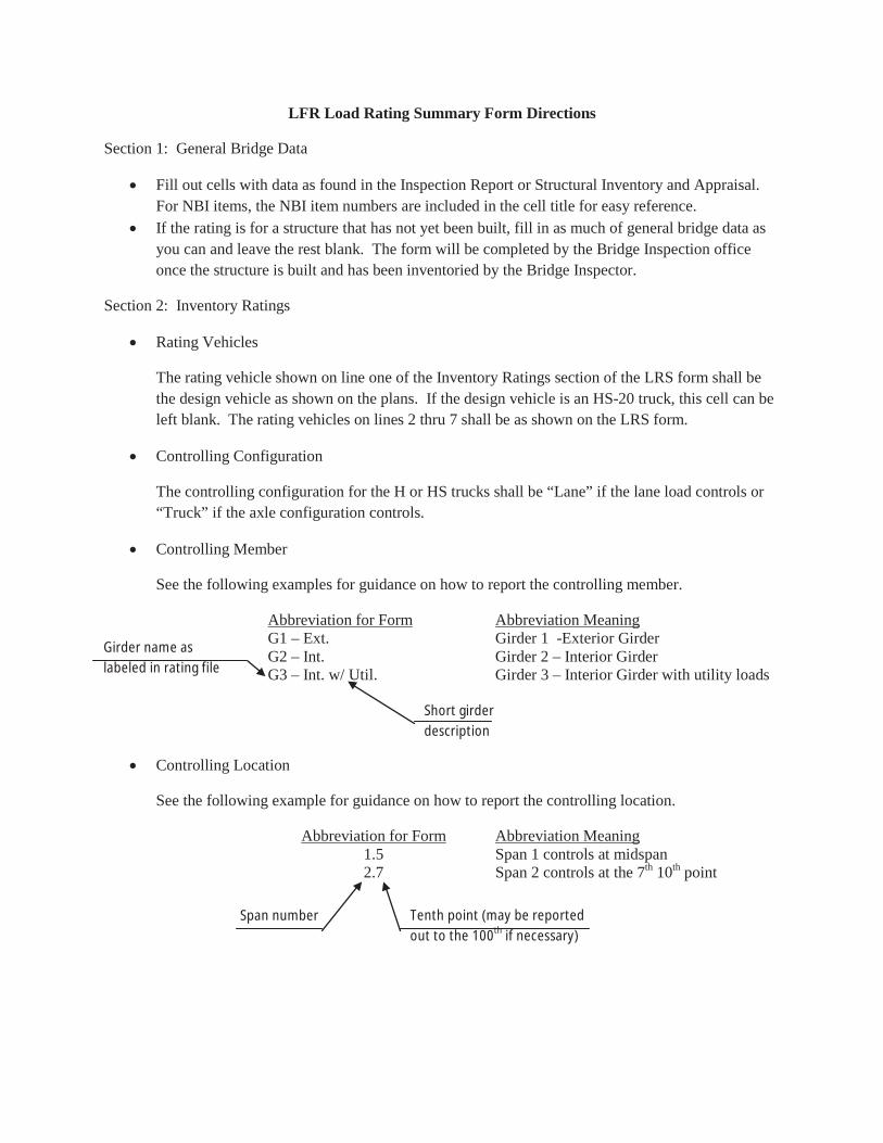
LFR Load Rating Summary Form Directions
Section 1: General Bridge Data
Fill out cells with data as found in the Inspection Report or Structural Inventory and Appraisal. For NBI items, the NBI item numbers are included in the cell title for easy reference.If the rating is for a structure that has not yet been built, fill in as much of general bridge data as you can and leave the rest blank. The form will be completed by the Bridge Inspection office once the structure is built and has been inventoried by the Bridge Inspector.
Section 2: Inventory Ratings
Rating Vehicles
The rating vehicle shown on line one of the Inventory Ratings section of the LRS form shall be the design vehicle as shown on the plans. If the design vehicle is an HS-20 truck, this cell can be left blank. The rating vehicles on lines 2 thru 7 shall be as shown on the LRS form.
Controlling Configuration
The controlling configuration for the H or HS trucks shall be “Lane” if the lane load controls or “Truck” if the axle configuration controls.
Controlling Member
See the following examples for guidance on how to report the controlling member.
Abbreviation for Form Abbreviation MeaningG1 – Ext. Girder 1 -Exterior GirderG2 – Int. Girder 2 – Interior GirderG3 – Int. w/ Util. Girder 3 – Interior Girder with utility loads
Controlling Location
See the following example for guidance on how to report the controlling location.
Abbreviation for Form Abbreviation Meaning1.5 Span 1 controls at midspan2.7 Span 2 controls at the 7th 10th point
Girder name as labeled in rating file
Short girder description
Span number Tenth point (may be reported out to the 100th if necessary)
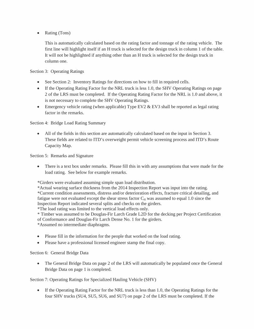
Rating (Tons)
This is automatically calculated based on the rating factor and tonnage of the rating vehicle. The first line will highlight itself if an H truck is selected for the design truck in column 1 of the table. It will not be highlighted if anything other than an H truck is selected for the design truck in column one.
Section 3: Operating Ratings
See Section 2: Inventory Ratings for directions on how to fill in required cells.If the Operating Rating Factor for the NRL truck is less 1.0, the SHV Operating Ratings on page 2 of the LRS must be completed. If the Operating Rating Factor for the NRL is 1.0 and above, it is not necessary to complete the SHV Operating Ratings. Emergency vehicle rating (when applicable) Type EV2 & EV3 shall be reported as legal rating factor in the remarks.
Section 4: Bridge Load Rating Summary
All of the fields in this section are automatically calculated based on the input in Section 3. These fields are related to ITD’s overweight permit vehicle screening process and ITD’s Route Capacity Map.
Section 5: Remarks and Signature
There is a text box under remarks. Please fill this in with any assumptions that were made for the load rating. See below for example remarks.
*Girders were evaluated assuming simple span load distribution.*Actual wearing surface thickness from the 2014 Inspection Report was input into the rating.*Current condition assessments, distress and/or deterioration effects, fracture critical detailing, and fatigue were not evaluated except the shear stress factor CH was assumed to equal 1.0 since the Inspection Report indicated several splits and checks on the girders.*The load rating was limited to the vertical load effects only.* Timber was assumed to be Douglas-Fir Larch Grade L2D for the decking per Project Certification of Conformance and Douglas-Fir Larch Dense No. 1 for the girders. *Assumed no intermediate diaphragms.
Please fill in the information for the people that worked on the load rating.Please have a professional licensed engineer stamp the final copy.
Section 6: General Bridge Data
The General Bridge Data on page 2 of the LRS will automatically be populated once the General Bridge Data on page 1 is completed.
Section 7: Operating Ratings for Specialized Hauling Vehicle (SHV)
If the Operating Rating Factor for the NRL truck is less than 1.0, the Operating Ratings for the four SHV trucks (SU4, SU5, SU6, and SU7) on page 2 of the LRS must be completed. If the

Operating Rating Factor for the NRL truck is 1.0 or above, leave the Operating Ratings for the SHV blank.
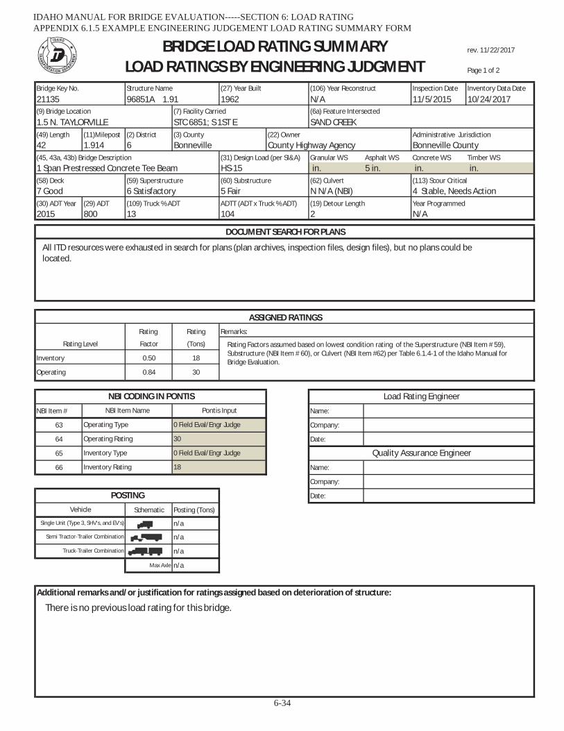
rev. 11/22/2017
Page 1 of 2
Bridge Key No. Structure Name (27) Year Built (106) Year Reconstruct Inspection Date Inventory Data Date
21135 96851A 1.91 1962 N/A 11/5/2015 10/24/2017(9) Bridge Location (7) Facility Carried (6a) Feature Intersected
1.5 N. TAYLORVILLE STC 6851; S 1ST E SAND CREEK(49) Length (11)Milepost (2) District (3) County (22) Owner Administrative Jurisdiction42 1.914 6 Bonneville County Highway Agency Bonneville County(45, 43a, 43b) Bridge Description (31) Design Load (per SI&A) Granular WS Asphalt WS Concrete WS Timber WS1 Span Prestressed Concrete Tee Beam HS 15 in. 5 in. in. in.(58) Deck (59) Superstructure (60) Substructure (62) Culvert (113) Scour Critical7 Good 6 Satisfactory 5 Fair N N/A (NBI) 4 Stable, Needs Action(30) ADT Year (29) ADT (109) Truck % ADT ADTT (ADT x Truck % ADT) (19) Detour Length Year Programmed2015 800 13 104 2 N/A
Rating Rating
Factor (Tons)
0.50 18
0.84 30
NBI Item # Name:
63 Company:
64 Date:
65
66 Name:
Company:
Date:
Schematic Posting (Tons)
n/a
n/a
n/a
Max Axle n/a
BRIDGE LOAD RATING SUMMARYLOAD RATINGS BY ENGINEERING JUDGMENT
NBI CODING IN PONTIS
Rating Level
DOCUMENT SEARCH FOR PLANS
ASSIGNED RATINGSRemarks:
Operating
Inventory
Load Rating Engineer
Inventory Type 0 Field Eval/Engr Judge
NBI Item Name Pontis Input
Operating Type 0 Field Eval/Engr Judge
Operating Rating 30
Semi Tractor Trailer Combination
Quality Assurance EngineerInventory Rating 18
Vehicle
POSTING
Single Unit (Type 3, SHV's, and EV's)
Truck Trailer Combination
Additional remarks and/or justification for ratings assigned based on deterioration of structure:
All ITD resources were exhausted in search for plans (plan archives, inspection files, design files), but no plans could belocated.
Rating Factors assumed based on lowest condition rating of the Superstructure (NBI Item # 59),Substructure (NBI Item # 60), or Culvert (NBI Item #62) per Table 6.1.4 1 of the Idaho Manual forBridge Evaluation.
There is no previous load rating for this bridge.
IDAHO MANUAL FOR BRIDGE EVALUATION-----SECTION 6: LOAD RATING APPENDIX 6.1.5 EXAMPLE ENGINEERING JUDGEMENT LOAD RATING SUMMARY FORM
6-34
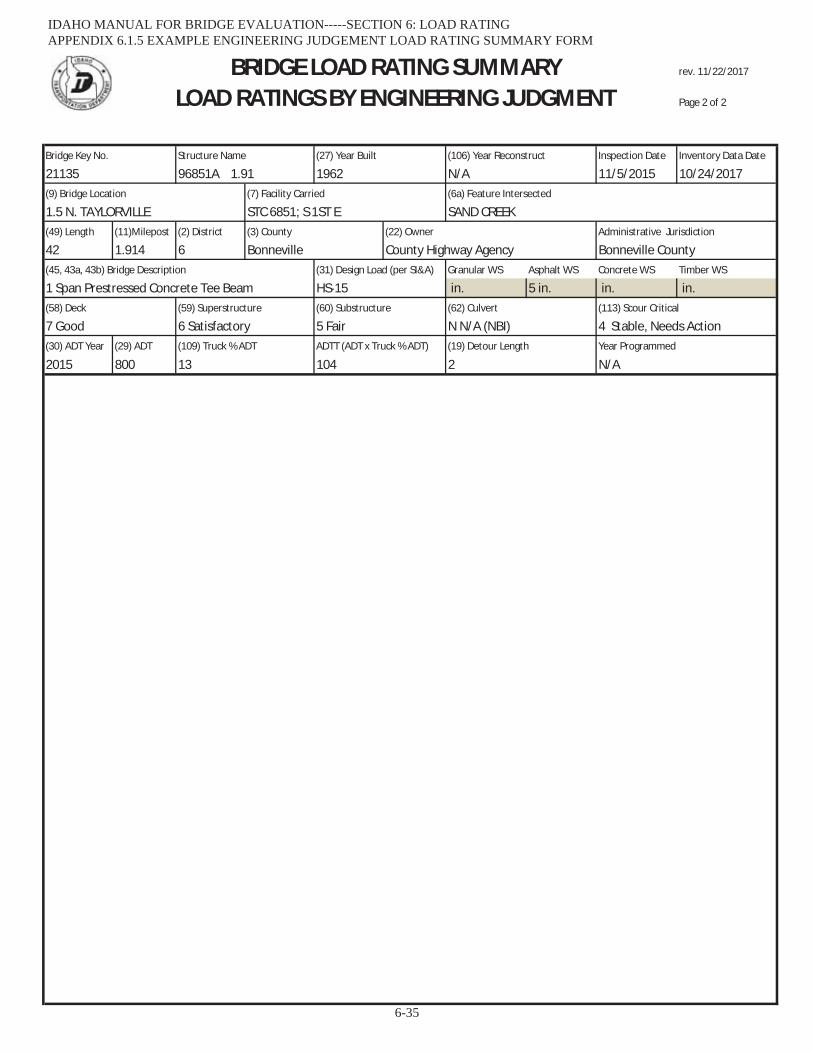
rev. 11/22/2017
Page 2 of 2
Bridge Key No. Structure Name (27) Year Built (106) Year Reconstruct Inspection Date Inventory Data Date
21135 96851A 1.91 1962 N/A 11/5/2015 10/24/2017(9) Bridge Location (7) Facility Carried (6a) Feature Intersected
1.5 N. TAYLORVILLE STC 6851; S 1ST E SAND CREEK(49) Length (11)Milepost (2) District (3) County (22) Owner Administrative Jurisdiction
42 1.914 6 Bonneville County Highway Agency Bonneville County(45, 43a, 43b) Bridge Description (31) Design Load (per SI&A) Granular WS Asphalt WS Concrete WS Timber WS
1 Span Prestressed Concrete Tee Beam HS 15 in. 5 in. in. in.(58) Deck (59) Superstructure (60) Substructure (62) Culvert (113) Scour Critical
7 Good 6 Satisfactory 5 Fair N N/A (NBI) 4 Stable, Needs Action(30) ADT Year (29) ADT (109) Truck % ADT ADTT (ADT x Truck % ADT) (19) Detour Length Year Programmed
2015 800 13 104 2 N/A
BRIDGE LOAD RATING SUMMARYLOAD RATINGS BY ENGINEERING JUDGMENT
IDAHO MANUAL FOR BRIDGE EVALUATION-----SECTION 6: LOAD RATING APPENDIX 6.1.5 EXAMPLE ENGINEERING JUDGEMENT LOAD RATING SUMMARY FORM
6-35

rev. 2/14/2017
(49) Length (11)Milepost (2) District28 ft 254.300 2
6 in. Asphalt 330 in. Granular
(30) ADT Year (29) ADT2015 3300
Rating Rating
Factor (Tons)
2.775 99.9
2.775 99.9
NBI Item # Name:
63 Company:
64 Date:
65
66 Name:
Company:
Date:
n/a
Idaho Type 3 3 n/a
Max Axle n/a
Bridge Key No. Structure Name Inspection Date(106) Year Reconstruct(27) Year Built
(9) Bridge Location (7) Facility Carried (6a) Feature Intersected
18369 09520D 254.30 1978 n/a 2/6/2017
6 Deterioration(113) Scour Critical8 Stable Above Footing
(58) Deck (59) Superstructure (60) SubstructureN N/A (NBI) N N/A (NBI) N N/A (NBI)
Dist. 2Administrative Jurisdiction(3) County
49 Idaho
(62) Culvert
Operating
Rating Level
DOCUMENT SEARCH FOR PLANS
ASSIGNED RATINGSRemarks:
Inventory
BURIED STRUCTURE LOAD RATING SUMMARYLOAD RATINGS BY LFR
(109) Truck % ADT ADTT (ADT x Truck % ADT) (19) Detour Length Year Programmed
S. of Cottonwood SCL US 95 Cottonwood Creek
(45, 43a, 43b) Bridge Description (31) Design Load (per SI&A)1 Span Steel Culvert HS 20
Existing Wearing Surface Type & Depth
(22) OwnerState Hwy Agency
20 660 1 mile n/a or unknown
NBI CODING IN PONTIS Load Rating EngineerNBI Item Name Pontis Input
Operating Type 1 Load Factor (LFR)
Operating Rating 99.9
Additional remarks and/or justification for ratings assigned based on deterioration of structure:
Inventory Type 1 Load Factor (LFR) Quality Assurance EngineerInventory Rating 99.9
POSTING
Vehicle Recommended Post (Tons)
Idaho Type 3 n/a
Idaho Type 3S2
Plans were found under Drawing # 16774. The design plans show a 132 inch diameter corrugated plate pipe on a 68.25degree skew (measured normal to the roadway). Depth of fill per the plans is (Elev. @ Road Centerline = 3490 ft; Elev. @Top of Pipe = 3464 ft; 3490 ft 3464 ft = 26 ft).
The HS 20 inventory and operating ratings are being input as 99.9 tons in accordance withIMBE Article 6.0.7.6 and the guidance for Items 64 and 66 found in the Idaho Bridge InspectionCoding Guide, January 2014, for structures under sufficient fill that live load is neglible.
There is no previous load rating for this structure.The structural span of this bridge is 11 feet since it is a 132 inch diameter pipe. Since the depth of fill is 28 feet (330 inch granularand 6 inch asphalt per 2017 inspection), live load effects have been neglected on this structure per AASHTO Standard SpecificationsArticle 6.4.2. . 11ft/cos(68.25) = 29.7ft
IDAHO MANUAL FOR BRIDGE EVALUATION-----SECTION 6: LOAD RATING APPENDIX 6.1.6 EXAMPLE LFR FOR CULVERTS WITH MORE THAN 8' FILL
6-36
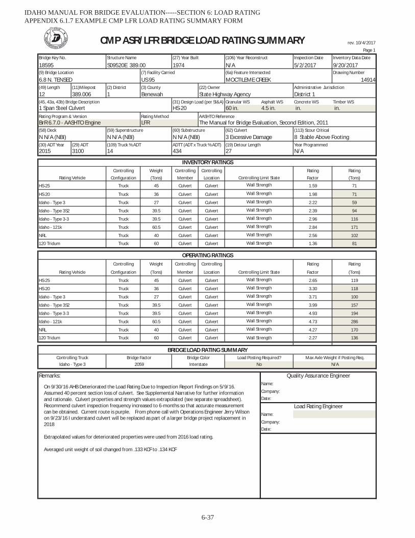
rev. 10/4/2017
Page 1
Bridge Key No. Structure Name (27) Year Built (106) Year Reconstruct Inspection Date Inventory Data Date
18595 S09520E 389.00 1974 N/A 5/2/2017 9/20/2017(9) Bridge Location (7) Facility Carried (6a) Feature Intersected Drawing Number
6.8 N. TENSED US 95 MOCTILEME CREEK 14914(49) Length (11)Milepost (2) District (3) County (22) Owner Administrative Jurisdiction
12 389.006 1 Benewah State Highway Agency District 1(45, 43a, 43b) Bridge Description (31) Design Load (per SI&A) Granular WS Asphalt WS Concrete WS Timber WS1 Span Steel Culvert HS 20 60 in. 4.5 in. in. in.Rating Program & Version Rating Method AASHTO ReferenceBrR 6.7.0 AASHTO Engine LFR The Manual for Bridge Evaluation, Second Edition, 2011(58) Deck (59) Superstructure (60) Substructure (62) Culvert (113) Scour Critical
N N/A (NBI) N N/A (NBI) N N/A (NBI) 3 Excessive Damage 8 Stable Above Footing(30) ADT Year (29) ADT (109) Truck % ADT ADTT (ADT x Truck % ADT) (19) Detour Length Year Programmed2015 3100 14 434 27 N/A
Controlling Weight Controlling Controlling Rating Rating
Configuration (Tons) Member Location Factor (Tons)
Truck 45 Culvert Culvert 1.59 71
Truck 36 Culvert Culvert 1.98 71
Truck 27 Culvert Culvert 2.22 59
Truck 39.5 Culvert Culvert 2.39 94
Truck 39.5 Culvert Culvert 2.96 116
Truck 60.5 Culvert Culvert 2.84 171
Truck 40 Culvert Culvert 2.56 102
Truck 60 Culvert Culvert 1.36 81
Controlling Weight Controlling Controlling Rating Rating
Configuration (Tons) Member Location Factor (Tons)
Truck 45 Culvert Culvert 2.65 119
Truck 36 Culvert Culvert 3.30 118
Truck 27 Culvert Culvert 3.71 100
Truck 39.5 Culvert Culvert 3.99 157
Truck 39.5 Culvert Culvert 4.93 194
Truck 60.5 Culvert Culvert 4.73 286
Truck 40 Culvert Culvert 4.27 170
Truck 60 Culvert Culvert 2.27 136
Remarks:Name:
Company:Date:
Name:
Company:Date:
Load Rating Engineer
Idaho 121k
NRL Wall Strength
Bridge Color
120 Tridum Wall Strength
Quality Assurance Engineer
HS 20 Wall Strength
Wall Strength
No
BRIDGE LOAD RATING SUMMARYControlling Truck Bridge Factor Load Posting Required? Max Axle Weight if Posting Req.
Idaho Type 3 2059 Interstate N/A
Idaho Type 3S2 Wall Strength
Idaho Type 3 3 Wall Strength
Idaho Type 3 Wall Strength
NRL Wall Strength
Controlling Limit State
Wall Strength
OPERATING RATINGS
Rating Vehicle
HS 25
120 Tridum Wall Strength
Idaho 121k
Rating Vehicle
Wall Strength
Idaho Type 3S2
Wall Strength
HS 20 Wall Strength
CMP ASR/LFR BRIDGE LOAD RATING SUMMARY
INVENTORY RATINGS
Wall Strength
Wall Strength
HS 25
Controlling Limit StateWall Strength
Idaho Type 3
Idaho Type 3 3
On 9/30/16 AHB Deteriorated the Load Rating Due to Inspection Report Findings on 5/9/16.Assumed 40 percent section loss of culvert. See Supplemental Narrative for further informationand rationale. Culvert properties and strength values extrapolated (see separate spreadsheet).Recommend culvert inspection frequency increased to 6 months so that accurate measurementcan be obtained. Current route is purple. From phone call with Operations Engineer Jerry Wilsonon 9/23/16 I understand culvert will be replaced as part of a larger bridge project replacement in2018
Extrapolated values for deteriorated properties were used from 2016 load rating.
Averaged unit weight of soil changed from .133 KCF to .134 KCF
IDAHO MANUAL FOR BRIDGE EVALUATION-----SECTION 6: LOAD RATING APPENDIX 6.1.7 EXAMPLE CMP LFR LOAD RATING SUMMARY FORM
6-37

rev. 10/4/2017
Page 2 of 2
Bridge Key No. Structure Name (27) Year Built (106) Year Reconstruct Inspection Date Inventory Data Date
18595 S09520E 389.00 1974 N/A 42857 42998(9) Bridge Location (7) Facility Carried (6a) Feature Intersected Drawing Number
6.8 N. TENSED US 95 MOCTILEME CREEK 14914(49) Length (11)Milepost (2) District (3) County (22) Owner Administrative Jurisdiction
12 389.006 1 Benewah State Highway Agency District 1(45, 43a, 43b) Bridge Description (31) Design Load (per SI&A) Granular WS Asphalt WS Concrete WS Timber WS
1 Span Steel Culvert HS 20 60 in. 4.5 in. in. in.Rating Program & Version Rating Method AASHTO Reference
BrR 6.7.0 AASHTO Engine LFR The Manual for Bridge Evaluation, Second Edition, 2011(58) Deck (59) Superstructure (60) Substructure (62) Culvert (113) Scour Critical
N N/A (NBI) N N/A (NBI) N N/A (NBI) 3 Excessive Damage 8 Stable Above Footing(30) ADT Year (29) ADT (109) Truck % ADT ADTT (ADT x Truck % ADT) (19) Detour Length Year Programmed
2015 3100 14 434 27 N/A
Controlling Weight Controlling Controlling Rating Rating
Configuration (Tons) Member Location Factor (Tons)
Truck 27 0
Truck 31 0
Truck 34.75 0
Truck 38.75 0
Posting
Vehicle Schematic (Tons)
N/A
N/A
N/A
Max Axle N/A
Additional Remarks:
CMP ASR/LFR BRIDGE LOAD RATING SUMMARY
SU6
SU7
OPERATING RATINGS Specialized Hauling Vehicles (SHV)
Rating Vehicle Controlling Limit State
SU4
SU5
(Fill in the below SHV OperatingRatings only when Operating Rating Factor for NRL is less than 1.0)
Single Unit
Semi Tractor Trailer Combination
Truck Trailer Combination
POSTING
IDAHO MANUAL FOR BRIDGE EVALUATION-----SECTION 6: LOAD RATING APPENDIX 6.1.7 EXAMPLE CMP LFR LOAD RATING SUMMARY FORM
6-38
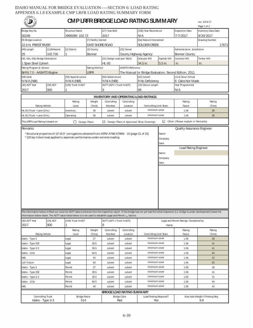
rev. 10/4/17
Page 1 of 2
Bridge Key No. Structure Name (27) Year Built (106) Year Reconstruct Inspection Date Inventory Data Date
30248 X995090 102.73 2017 N/A 7/7/2017 9/20/2017(9) Bridge Location (7) Facility Carried (6a) Feature Intersected Drawing Number
22.6 N. PRIEST RIVER EAST SHORE ROAD SOLDIER CREEK 17671(49) Length (11)Milepost (2) District (3) County (22) Owner Administrative Jurisdiction
25 102.726 1 Bonner County Highway Agency Bonner County(45, 43a, 43b) Bridge Description (31) Design Load (per SI&A) Granular WS Asphalt WS Concrete WS Timber WS
1 Span Steel Culvert HL 93 34.5 in. 5.5 in. in. in.Rating Program & Version Rating Method AASHTO Reference
BrR 6.7.0 AASHTO Engine LRFR The Manual for Bridge Evaluation, Second Edition, 2011(58) Deck (59) Superstructure (60) Substructure (62) Culvert (113) Scour Critical
N N/A (NBI) N N/A (NBI) N N/A (NBI) 9 No Deficiency 6 Calcs Not Made(30) ADT Year (29) ADT (109) Truck % ADT ADTT (ADT x Truck % ADT) (19) Detour Length Year Programmed
2017 900 1 9 99 N/A
Rating Weight Controlling Controlling Rating Rating
Level (Tons) Member Location Factor (Tons)
Inventory 36 culvert culvert 1.06 38
Operating 36 culvert culvert 1.06 38
This LRFR Load Rating is based on:
Remarks:Name:
Company:
Date:
Name:
Company:
Date:
(30) ADT Year (29) ADT
2017 900Rating Weight Controlling Controlling Rating RatingLevel (Tons) Member Location Factor (Tons)
Legal 27 culvert culvert 1.06 28
Legal 39.5 culvert culvert 1.06 41
Legal 39.5 culvert culvert 1.06 41
Legal 60.5 culvert culvert 1.06 64
Legal 40 culvert culvert 1.06 42
Legal 60 culvert culvert 1.06 63
Permit 27 culvert culvert 1.06 28
Permit 39.5 culvert culvert 1.06 41
Permit 39.5 culvert culvert 1.06 41
Permit 60.5 culvert culvert 1.06 64
Permit 40 culvert culvert 1.06 42
Legal and Permit Ratings Completed by
Idaho 121k minimum cover
minimum cover
Idaho Type 3S2
Idaho Type 3 minimum cover
minimum cover
Idaho Type 3 3
120 Tridum minimum cover
Rating Vehicle
INVENTORY AND OPERATING LOAD RATINGS
Controlling Limit State
(109) Truck % ADT ADTT (ADT x Truck % ADT)
1 9 Name:
HL 93 (Truck + Lane Ctrls.) minimum cover
Quality Assurance Engineer
Load Rating Engineer
CMP LRFR BRIDGE LOAD RATING SUMMARY
The information below is filled out once the ADTT data is entered onto the inspection report. If this bridge has not yet had the initial inspection (i.e. bridge is under development) leave theinformation below blank. The ADTT value listed below is to be used to establish Legal and Permit LL factors.
Controlling Limit Stateminimum cover
Rating Vehicle
HL 93 (Truck + Lane Ctrls.)
NRL minimum cover
Idaho 121k minimum cover
NRL minimum cover
minimum coverIdaho Type 3 3
Idaho Type 3 minimum cover
Idaho Type 3S2 minimum cover
Idaho Type 3 3 514 Red Yes
BRIDGE LOAD RATING SUMMARY
9.8Controlling Truck Bridge Factor Load Posting Required? Max Axle Weight if Posting Req.Bridge Color
*Structural properties of 15"x5.5" corrugations obtained from ASTM A796/A796M 10 (page 21 of 22)*120 kip tridum load applied to ascertain performance under extreme loading
Design Plans & Approved Shop DrawingsDesign Plans Other (Please explain in Remarks)
IDAHO MANUAL FOR BRIDGE EVALUATION-----SECTION 6: LOAD RATING APPENDIX 6.1.8 EXAMPLE CMP LRFR LOAD RATING SUMMARY FORM
6-39
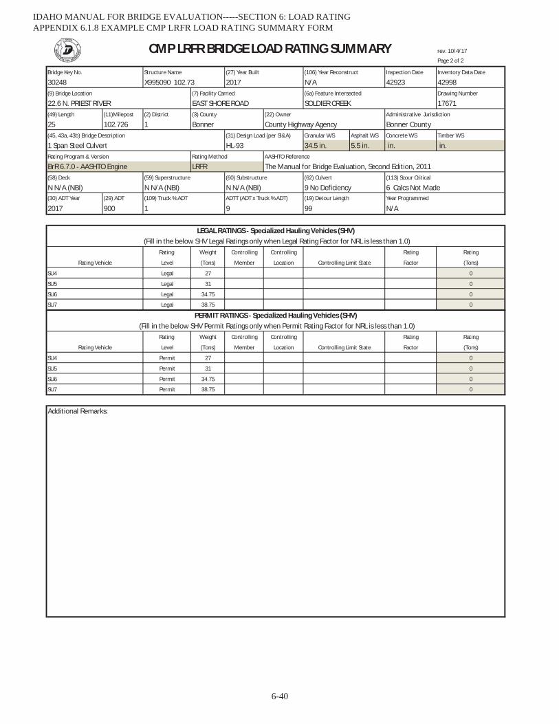
rev. 10/4/17
Page 2 of 2
Bridge Key No. Structure Name (27) Year Built (106) Year Reconstruct Inspection Date Inventory Data Date
30248 X995090 102.73 2017 N/A 42923 42998(9) Bridge Location (7) Facility Carried (6a) Feature Intersected Drawing Number
22.6 N. PRIEST RIVER EAST SHORE ROAD SOLDIER CREEK 17671(49) Length (11)Milepost (2) District (3) County (22) Owner Administrative Jurisdiction
25 102.726 1 Bonner County Highway Agency Bonner County(45, 43a, 43b) Bridge Description (31) Design Load (per SI&A) Granular WS Asphalt WS Concrete WS Timber WS
1 Span Steel Culvert HL 93 34.5 in. 5.5 in. in. in.Rating Program & Version Rating Method AASHTO Reference
BrR 6.7.0 AASHTO Engine LRFR The Manual for Bridge Evaluation, Second Edition, 2011(58) Deck (59) Superstructure (60) Substructure (62) Culvert (113) Scour Critical
N N/A (NBI) N N/A (NBI) N N/A (NBI) 9 No Deficiency 6 Calcs Not Made(30) ADT Year (29) ADT (109) Truck % ADT ADTT (ADT x Truck % ADT) (19) Detour Length Year Programmed
2017 900 1 9 99 N/A
Rating Weight Controlling Controlling Rating Rating
Level (Tons) Member Location Factor (Tons)
Legal 27 0
Legal 31 0
Legal 34.75 0
Legal 38.75 0
Rating Weight Controlling Controlling Rating Rating
Level (Tons) Member Location Factor (Tons)
Permit 27 0
Permit 31 0
Permit 34.75 0
Permit 38.75 0
Additional Remarks:
SU4
SU5
(Fill in the below SHV Legal Ratings only when Legal Rating Factor for NRL is less than 1.0)LEGAL RATINGS Specialized Hauling Vehicles (SHV)
Rating Vehicle Controlling Limit State
CMP LRFR BRIDGE LOAD RATING SUMMARY
SU6
SU6
SU7
SU7
PERMIT RATINGS Specialized Hauling Vehicles (SHV)(Fill in the below SHV Permit Ratings only when Permit Rating Factor for NRL is less than 1.0)
Rating Vehicle Controlling Limit State
SU4
SU5
IDAHO MANUAL FOR BRIDGE EVALUATION-----SECTION 6: LOAD RATING APPENDIX 6.1.8 EXAMPLE CMP LRFR LOAD RATING SUMMARY FORM
6-40

IDAHO MANUAL FOR BRIDGE EVALUATION-----SECTION 6: LOAD RATING APPENDIX 6.2.1 IDAHO LEGAL TRUCK SCHEMATICS
6-41
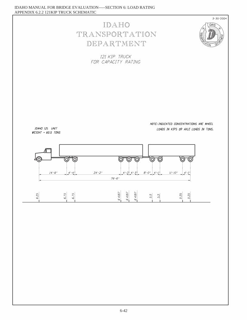
IDAHO MANUAL FOR BRIDGE EVALUATION-----SECTION 6: LOAD RATING APPENDIX 6.2.2 121KIP TRUCK SCHEMATIC
6-42

IDAHO MANUAL FOR BRIDGE EVALUATION-----SECTION 6: LOAD RATING APPENDIX 6.2.3 UNDER BRIDGE INSPECTION TRUCK SCHEMATIC
6-43
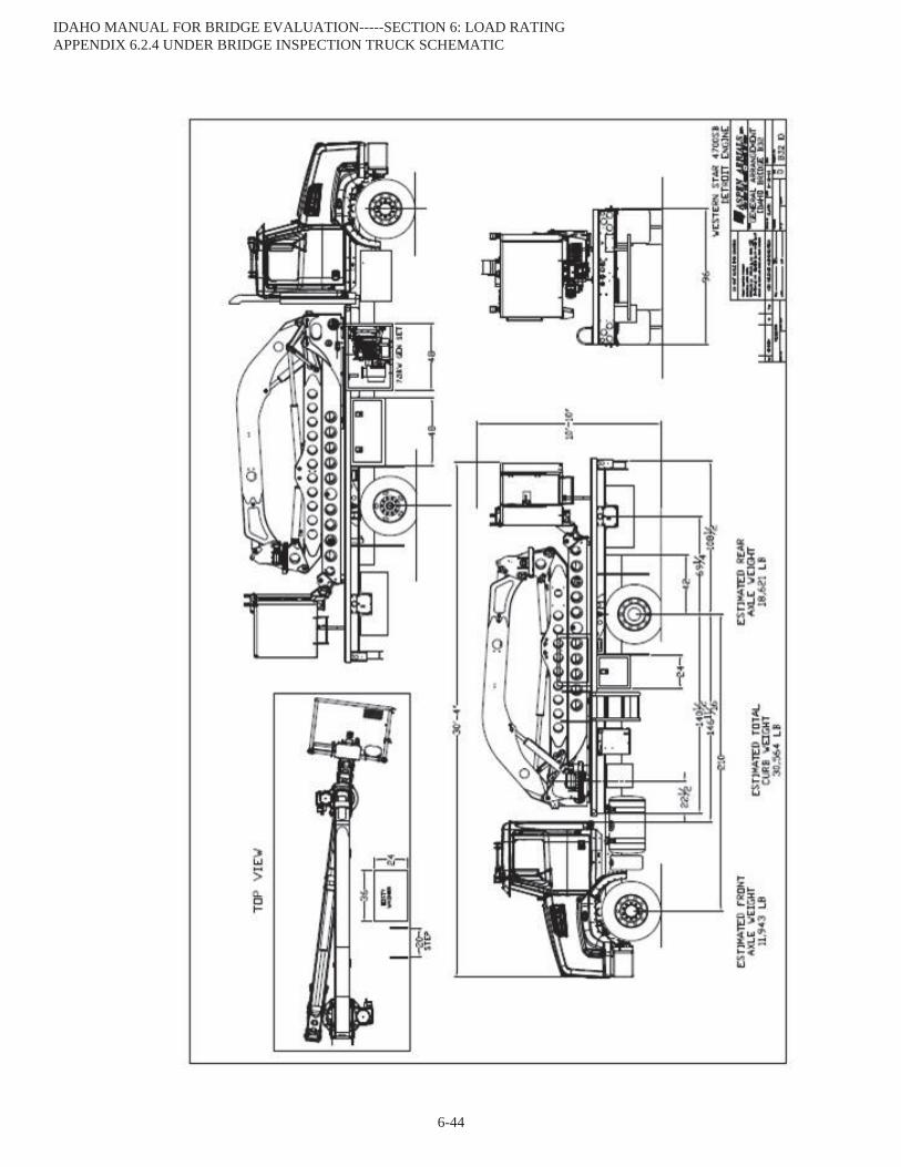
IDAHO MANUAL FOR BRIDGE EVALUATION-----SECTION 6: LOAD RATING APPENDIX 6.2.4 UNDER BRIDGE INSPECTION TRUCK SCHEMATIC
6-44
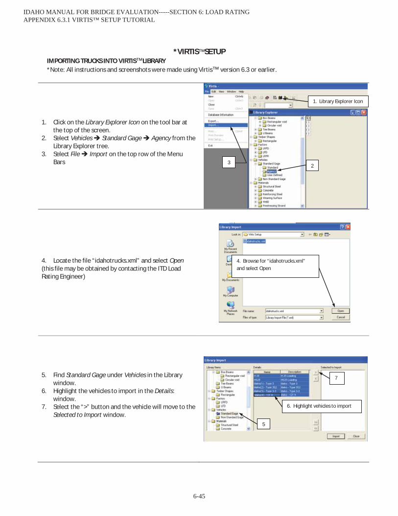
*VIRTIS™ SETUPIMPORTING TRUCKS INTO VIRTIS™ LIBRARY *Note: All instructions and screenshots were made using Virtis™ version 6.3 or earlier.
1. Click on the Library Explorer Icon on the tool bar atthe top of the screen.
2. Select Vehicles Standard Gage Agency from theLibrary Explorer tree.
3. Select File Import on the top row of the MenuBars
4. Locate the file “idahotrucks.xml” and select Open(this file may be obtained by contacting the ITD Load Rating Engineer)
5. Find Standard Gage under Vehicles in the Librarywindow.
6. Highlight the vehicles to import in the Details:window.
7. Select the “>” button and the vehicle will move to theSelected to Import window.
5
6. Highlight vehicles to import
7
1. Library Explorer Icon
2 3
4. Browse for “idahotrucks.xml” and select Open
IDAHO MANUAL FOR BRIDGE EVALUATION-----SECTION 6: LOAD RATING APPENDIX 6.3.1 VIRTIS™ SETUP TUTORIAL
6-45

8. When all vehicles have been moved to the Selected to Import window, select the Import button.
The imported vehicles will now be located in the Agency folder.
8
IDAHO MANUAL FOR BRIDGE EVALUATION-----SECTION 6: LOAD RATING APPENDIX 6.3.1 VIRTIS™ SETUP TUTORIAL
6-46

SETTING UP AN ANALYSIS TEMPLATE IN VIRTIS™
1. Click on the Bridge Explorer Icon on the tool bar atthe top of the screen.
2. Open any bridge in the Bridge Explorer window bydouble clicking on the row it appears in.
3. Select Bridge Analysis Settings from the topmenu row.
4. Select the Vehicles tab.5. Select a rating method in the Rating Menu drop
down menu. This example is for LFD, but thatsame steps can be used for LRFR and AS.
6. Click on the works Rating Vehicles to highlight it inthe Vehicle Summary window. This will allow thevehicles that will be selected to be added to boththe Inventory and Operating lists at the same time.
7. Select a vehicle to move to the Vehicle Summary.8. Select the Add to Rating “>>” button. The selected
vehicle will now be part of the Inventory andOperating lists.
2. Double Click
3
4
1. Bridge Explorer Icon
5
6
7
8
IDAHO MANUAL FOR BRIDGE EVALUATION-----SECTION 6: LOAD RATING APPENDIX 6.3.1 VIRTIS™ SETUP TUTORIAL
6-47

9. Select the Output tab in the Analysis Settingwindow.
10. Select to generate all available output.
11. Select the Engine tab in the Analysis Settingswindow.
12. Select the engine desired from the pull downmenu.
13. Select the Properties button.
14. Select to print all available output and calculationsfor girder properties, dead load distribution,prestress losses, and P/S moment calculations.
9
10. Check all boxes
11 12
13
14. Check all boxes
IDAHO MANUAL FOR BRIDGE EVALUATION-----SECTION 6: LOAD RATING APPENDIX 6.3.1 VIRTIS™ SETUP TUTORIAL
6-48
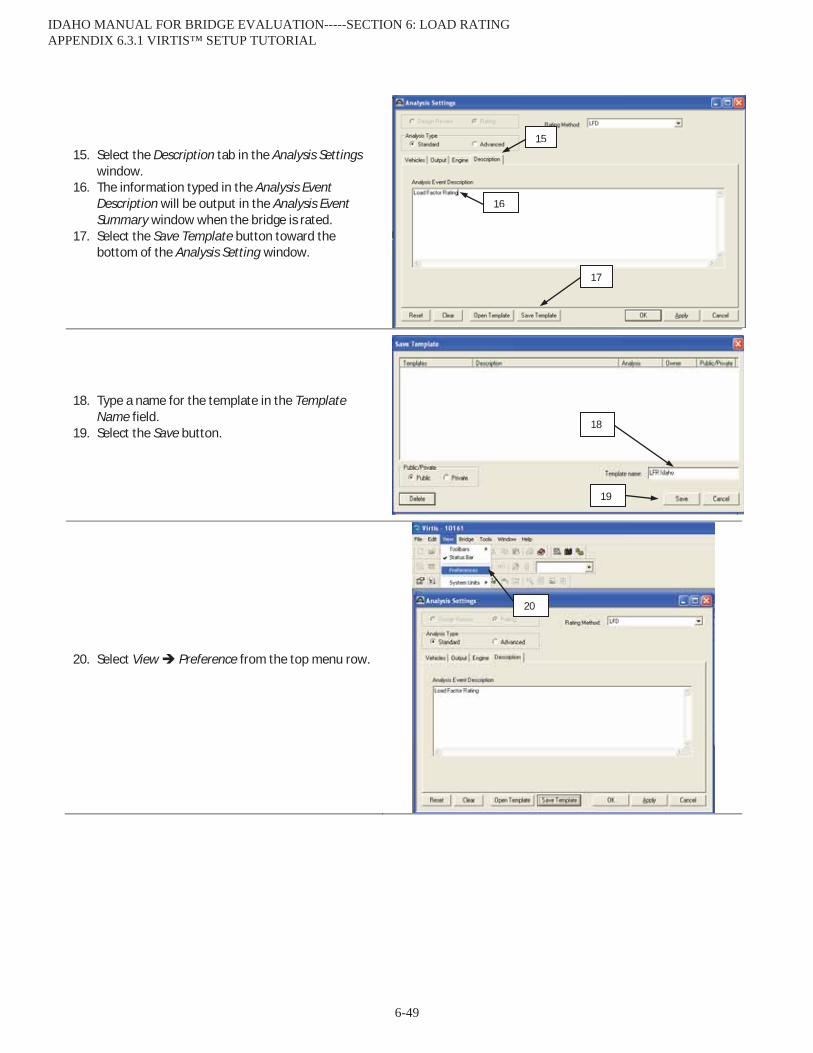
15. Select the Description tab in the Analysis Settingswindow.
16. The information typed in the Analysis EventDescription will be output in the Analysis EventSummary window when the bridge is rated.
17. Select the Save Template button toward thebottom of the Analysis Setting window.
18. Type a name for the template in the TemplateName field.
19. Select the Save button.
20. Select View Preference from the top menu row.
15
16
17
18
19
20
IDAHO MANUAL FOR BRIDGE EVALUATION-----SECTION 6: LOAD RATING APPENDIX 6.3.1 VIRTIS™ SETUP TUTORIAL
6-49

21. Select the Analysis tab in the Preferences window. 22. Select the template that has been created above
using the drop down menu under Default Analysis Setting Template.
The default template will now load with each bridge that is to be rated.
21
22
IDAHO MANUAL FOR BRIDGE EVALUATION-----SECTION 6: LOAD RATING APPENDIX 6.3.1 VIRTIS™ SETUP TUTORIAL
6-50
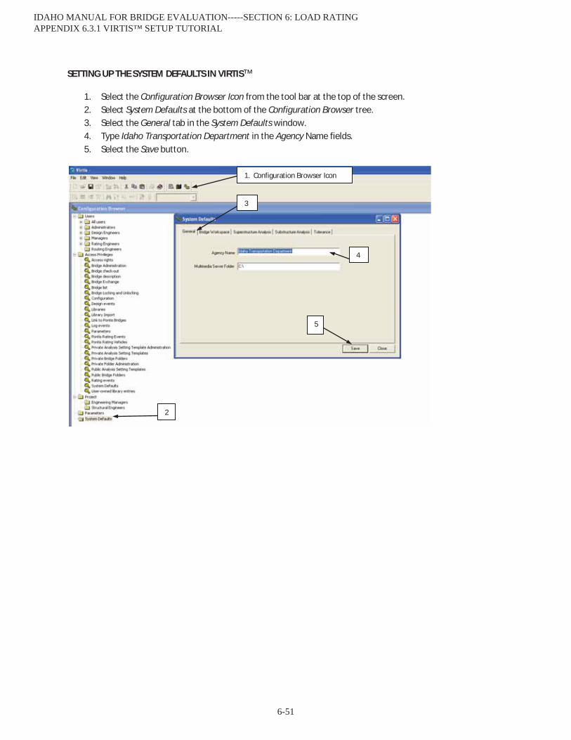
SETTING UP THE SYSTEM DEFAULTS IN VIRTIS™
1. Select the Configuration Browser Icon from the tool bar at the top of the screen. 2. Select System Defaults at the bottom of the Configuration Browser tree. 3. Select the General tab in the System Defaults window. 4. Type Idaho Transportation Department in the Agency Name fields. 5. Select the Save button.
1. Configuration Browser Icon
2
3
4
5
IDAHO MANUAL FOR BRIDGE EVALUATION-----SECTION 6: LOAD RATING APPENDIX 6.3.1 VIRTIS™ SETUP TUTORIAL
6-51
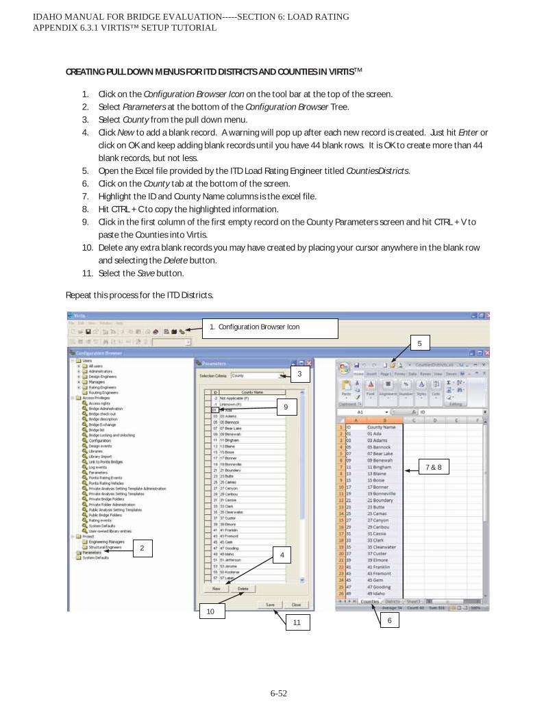
CREATING PULL DOWN MENUS FOR ITD DISTRICTS AND COUNTIES IN VIRTIS™
1. Click on the Configuration Browser Icon on the tool bar at the top of the screen. 2. Select Parameters at the bottom of the Configuration Browser Tree. 3. Select County from the pull down menu. 4. Click New to add a blank record. A warning will pop up after each new record is created. Just hit Enter or
click on OK and keep adding blank records until you have 44 blank rows. It is OK to create more than 44 blank records, but not less.
5. Open the Excel file provided by the ITD Load Rating Engineer titled CountiesDistricts. 6. Click on the County tab at the bottom of the screen. 7. Highlight the ID and County Name columns is the excel file. 8. Hit CTRL + C to copy the highlighted information. 9. Click in the first column of the first empty record on the County Parameters screen and hit CTRL + V to
paste the Counties into Virtis. 10. Delete any extra blank records you may have created by placing your cursor anywhere in the blank row
and selecting the Delete button. 11. Select the Save button.
Repeat this process for the ITD Districts.
1. Configuration Browser Icon
2
3
4
5
6
7 & 8
9
10 11
IDAHO MANUAL FOR BRIDGE EVALUATION-----SECTION 6: LOAD RATING APPENDIX 6.3.1 VIRTIS™ SETUP TUTORIAL
6-52

CREATING A NEW BRIDGE IN *VIRTIS™
CREATING A NEW BRIDGE *Note: All instructions and screenshots were made using Virtis™ version 6.3 or earlier.
1. Click on the Bridge Explorer Icon on the tool barat the top of the screen.
2. Select File New New Bridge from the topmenu row.
3. Fill the information on the Bridge ID field, NBIStructure ID field, Description tab, Description(cont’d) tab, Global Reference tab, and Traffictab per the instructions in Virtis Description Data.
4. Select the OK button.
5. You will now see a bridge workspace tree, readyfor data input. Click on the Save Icon on the toolbar at the top of the screen.
You have now created a bridge from scratch and have saved it to your database. You may complete your data input now, or exit (click on the red X button in the top right corner of the window) and return in the future to complete your input.
1. Bridge Explorer Icon
2
3
4
5
IDAHO MANUAL FOR BRIDGE EVALUATION-----SECTION 6: LOAD RATING APPENDIX 6.3.2 CREATING A NEW BRIDGE IN VIRTIS™
6-53

CREATING A NEW BRIDGE FROM A COPY OF AN EXISTING BRIDGE
1. Click on the Bridge Explorer Icon on thetoll bar at the top of the screen.
2. Highlight the bridge you would like tocopy.
3. Right click on the mouse and select Copy.
4. Right click on the mouse and selectPaste.
5. Modify the NBI Structure ID for the newbridge.
6. Select the OK button.
The copy has been saved and will now appear in Bridge Explorer and can be modified.
1. Bridge Explorer Icon
2 3
4
5
6
IDAHO MANUAL FOR BRIDGE EVALUATION-----SECTION 6: LOAD RATING APPENDIX 6.3.2 CREATING A NEW BRIDGE IN VIRTIS™
6-54
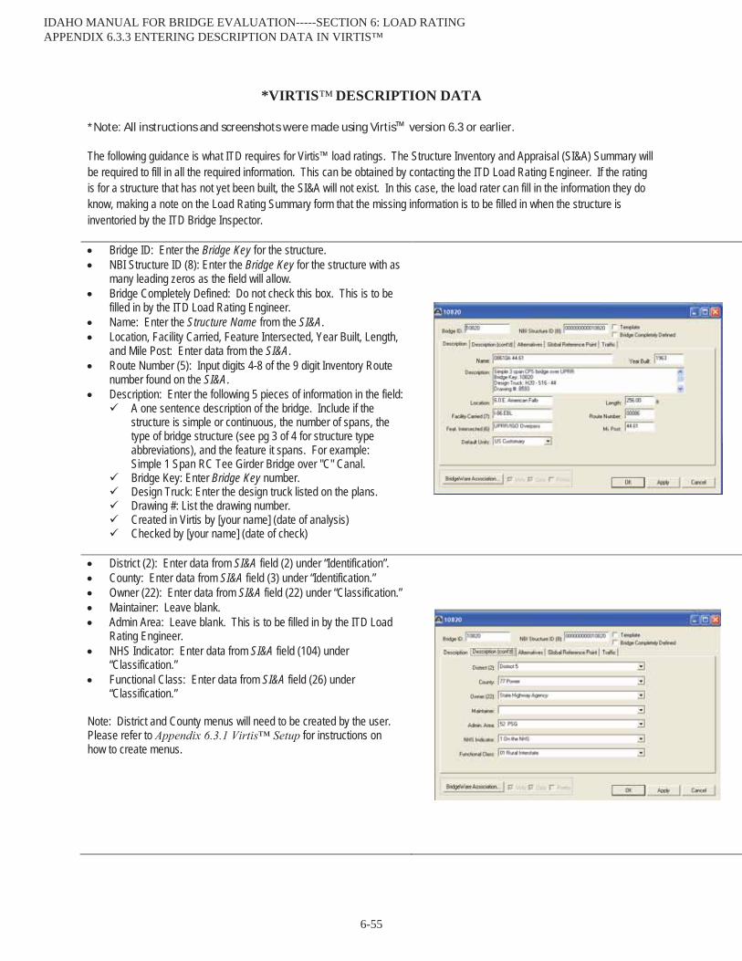
*VIRTIS™ DESCRIPTION DATA
*Note: All instructions and screenshots were made using Virtis™ version 6.3 or earlier.
The following guidance is what ITD requires for Virtis™ load ratings. The Structure Inventory and Appraisal (SI&A) Summary will be required to fill in all the required information. This can be obtained by contacting the ITD Load Rating Engineer. If the rating is for a structure that has not yet been built, the SI&A will not exist. In this case, the load rater can fill in the information they do know, making a note on the Load Rating Summary form that the missing information is to be filled in when the structure is inventoried by the ITD Bridge Inspector.
Bridge ID: Enter the Bridge Key for the structure.NBI Structure ID (8): Enter the Bridge Key for the structure with asmany leading zeros as the field will allow.Bridge Completely Defined: Do not check this box. This is to befilled in by the ITD Load Rating Engineer.Name: Enter the Structure Name from the SI&A.Location, Facility Carried, Feature Intersected, Year Built, Length,and Mile Post: Enter data from the SI&A.Route Number (5): Input digits 4-8 of the 9 digit Inventory Routenumber found on the SI&A.Description: Enter the following 5 pieces of information in the field:
A one sentence description of the bridge. Include if thestructure is simple or continuous, the number of spans, thetype of bridge structure (see pg 3 of 4 for structure typeabbreviations), and the feature it spans. For example:Simple 1 Span RC Tee Girder Bridge over "C" Canal.Bridge Key: Enter Bridge Key number.Design Truck: Enter the design truck listed on the plans.Drawing #: List the drawing number.Created in Virtis by [your name] (date of analysis)Checked by [you name] (date of check)
District (2): Enter data from SI&A field (2) under “Identification”.County: Enter data from SI&A field (3) under “Identification.”Owner (22): Enter data from SI&A field (22) under “Classification.”Maintainer: Leave blank.Admin Area: Leave blank. This is to be filled in by the ITD LoadRating Engineer.NHS Indicator: Enter data from SI&A field (104) under“Classification.”Functional Class: Enter data from SI&A field (26) under“Classification.”
Note: District and County menus will need to be created by the user.Please refer to for instructions onhow to create menus.
IDAHO MANUAL FOR BRIDGE EVALUATION-----SECTION 6: LOAD RATING APPENDIX 6.3.3 ENTERING DESCRIPTION DATA IN VIRTIS™
6-55

There will be nothing on this tab until a bridge alternative is created,further down the tree. Once a bridge alternative is created this tab will automatically populate. The rater does not need to do anything with this tab.
X = : Leave at default (0.00)Y = : Leave at default (0.00)Elevation: Leave blankLongitude (17): Input value from SI&A in degrees.Latitude (16): Input value from SI&A in degrees.
Truck PCT: Enter data from SI&A Update field (109) under “Ageand Service.”ADT: Enter data from SI&A field (29) under “Age and Service.”Directional PCT: Enter 100%Recent ADTT: Let Virtis calculate this value using the above data.Design ADTT: Use the same value as Recent ADTT
Enter the Name of Materials as listed below:Structural Steel: fy = X ksiConcrete: “f’c = X ksi”Reinforcing Steel: “Grade XX”Prestressing Strand: Use standard name that is copied fromthe Library
Enter the Name of Beam Shapes as listed below:Use the name that comes standard from the Library if theshape is copied from the Library.If the shape is not available to be copied from the Virtis BeamShape Library, use the name given to the girder on the plans.
Enter the Name of Appurtenances as shown. Make the namedescriptive of the appurtenance.
IDAHO MANUAL FOR BRIDGE EVALUATION-----SECTION 6: LOAD RATING APPENDIX 6.3.3 ENTERING DESCRIPTION DATA IN VIRTIS™
6-56
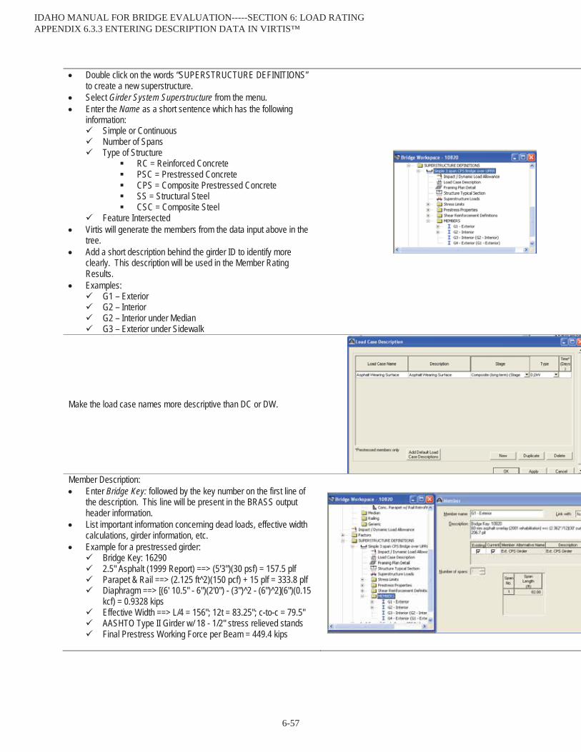
Double click on the words “SUPERSTRUCTURE DEFINITIONS” to create a new superstructure. Select Girder System Superstructure from the menu.Enter the Name as a short sentence which has the following information:
Simple or ContinuousNumber of SpansType of Structure
RC = Reinforced ConcretePSC = Prestressed ConcreteCPS = Composite Prestressed ConcreteSS = Structural SteelCSC = Composite Steel
Feature IntersectedVirtis will generate the members from the data input above in the tree.Add a short description behind the girder ID to identify more clearly. This description will be used in the Member Rating Results.Examples:
G1 – ExteriorG2 – InteriorG2 – Interior under MedianG3 – Exterior under Sidewalk
Make the load case names more descriptive than DC or DW.
Member Description:Enter Bridge Key: followed by the key number on the first line of the description. This line will be present in the BRASS output header information.List important information concerning dead loads, effective width calculations, girder information, etc.Example for a prestressed girder:
Bridge Key: 162902.5" Asphalt (1999 Report) ==> (5'3")(30 psf) = 157.5 plfParapet & Rail ==> (2.125 ft^2)(150 pcf) + 15 plf = 333.8 plfDiaphragm ==> [(6' 10.5" - 6")(2'0") - (3")^2 - (6")^2](6")(0.15 kcf) = 0.9328 kipsEffective Width ==> L/4 = 156"; 12t = 83.25"; c-to-c = 79.5"AASHTO Type II Girder w/ 18 - 1/2" stress relieved standsFinal Prestress Working Force per Beam = 449.4 kips
IDAHO MANUAL FOR BRIDGE EVALUATION-----SECTION 6: LOAD RATING APPENDIX 6.3.3 ENTERING DESCRIPTION DATA IN VIRTIS™
6-57

Member Alternative Description:Enter a more detailed description of the member.Include the type of girder (ie RC, CPS, PSC, SS, CSC, etc.)
Bridge Alternative: Give a very general description of the structure.Superstructure: Identify the span and material. This description will be listed in the Structure Rating Results & the Member Rating Results.Superstructure Alternative: Give a simple name (ie girders) and link to the appropriate superstructure definition.
IDAHO MANUAL FOR BRIDGE EVALUATION-----SECTION 6: LOAD RATING APPENDIX 6.3.3 ENTERING DESCRIPTION DATA IN VIRTIS™
6-58
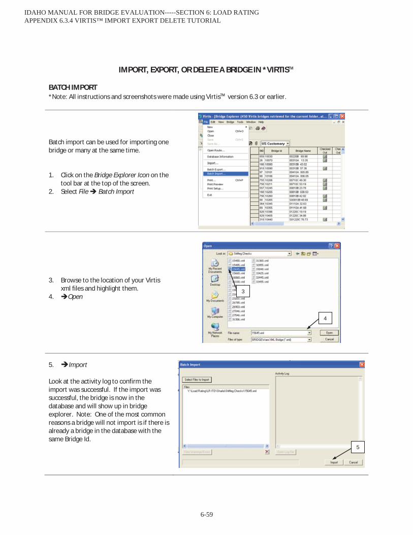
IMPORT, EXPORT, OR DELETE A BRIDGE IN *VIRTIS™
BATCH IMPORT *Note: All instructions and screenshots were made using Virtis™ version 6.3 or earlier.
Batch import can be used for importing one bridge or many at the same time. 1. Click on the Bridge Explorer Icon on the
tool bar at the top of the screen. 2. Select File Batch Import
3. Browse to the location of your Virtis xml files and highlight them.
4. Open
5. Import Look at the activity log to confirm the import was successful. If the import was successful, the bridge is now in the database and will show up in bridge explorer. Note: One of the most common reasons a bridge will not import is if there is already a bridge in the database with the same Bridge Id.
4
5
3
IDAHO MANUAL FOR BRIDGE EVALUATION-----SECTION 6: LOAD RATING APPENDIX 6.3.4 VIRTIS™ IMPORT EXPORT DELETE TUTORIAL
6-59
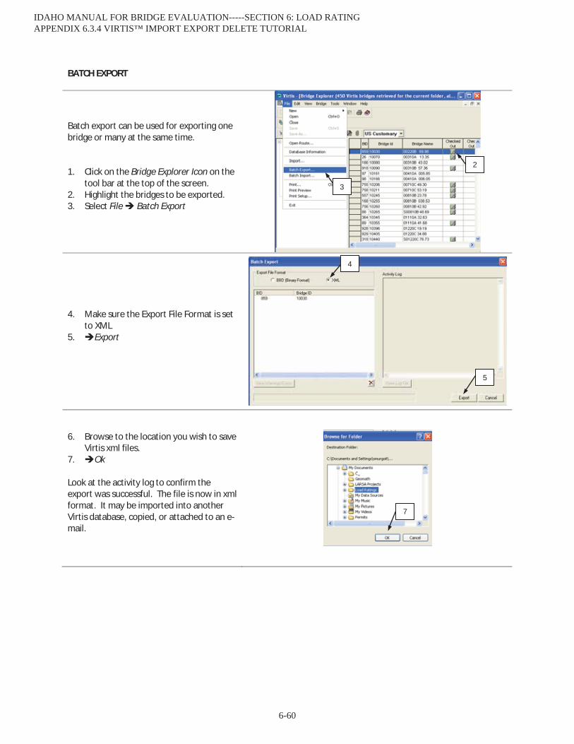
BATCH EXPORT
Batch export can be used for exporting one bridge or many at the same time. 1. Click on the Bridge Explorer Icon on the
tool bar at the top of the screen. 2. Highlight the bridges to be exported. 3. Select File Batch Export
4. Make sure the Export File Format is set to XML
5. Export
6. Browse to the location you wish to save Virtis xml files.
7. Ok Look at the activity log to confirm the export was successful. The file is now in xml format. It may be imported into another Virtis database, copied, or attached to an e-mail.
2
3
5
7
4
IDAHO MANUAL FOR BRIDGE EVALUATION-----SECTION 6: LOAD RATING APPENDIX 6.3.4 VIRTIS™ IMPORT EXPORT DELETE TUTORIAL
6-60

ITD MODIFICATIONS TO *VIRTIS™ STANDARD SETTINGS
CHECK SHEAR AT THE LEGAL AND PERMIT LEVEL AND CONCRETE TENSION AT THE LEGAL LEVEL FOR LRFR RATINGS *Note: All instructions and screenshots were made using Virtis™ version 6.3 or earlier.
1. Double click on each member alternative defined.
2. Select the Control Options tab 3. Select the LRFD Options are as shown
1
3
2
IDAHO MANUAL FOR BRIDGE EVALUATION-----SECTION 6: LOAD RATING APPENDIX 6.3.5 MODIFICATIONS TO STANDARD VIRTIS™ SETTINGS
6-61
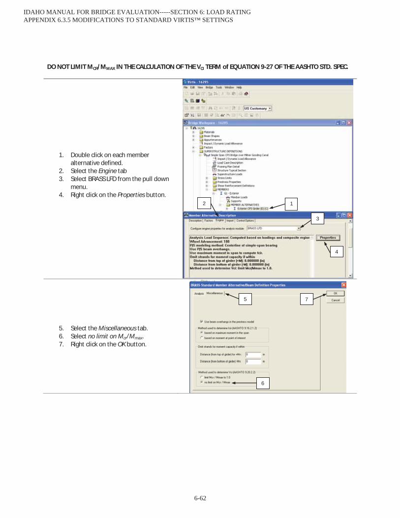
DO NOT LIMIT MCR/MMAX IN THE CALCULATION OF THE VCI TERM of EQUATION 9-27 OF THE AASHTO STD. SPEC.
1. Double click on each member alternative defined.
2. Select the Engine tab 3. Select BRASS LFD from the pull down
menu. 4. Right click on the Properties button.
5. Select the Miscellaneous tab. 6. Select no limit on Mcr/Mmax. 7. Right click on the OK button.
12
3
5
4
6
7
IDAHO MANUAL FOR BRIDGE EVALUATION-----SECTION 6: LOAD RATING APPENDIX 6.3.5 MODIFICATIONS TO STANDARD VIRTIS™ SETTINGS
6-62
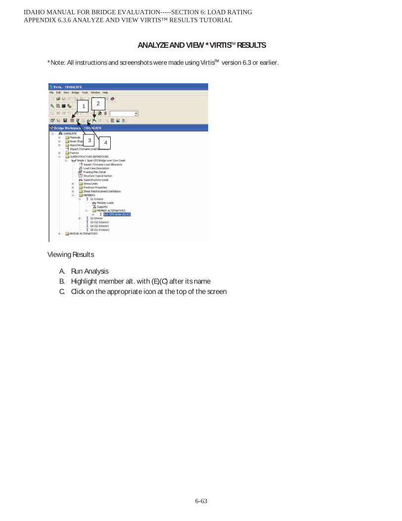
ANALYZE AND VIEW *VIRTIS™RESULTS
*Note: All instructions and screenshots were made using Virtis™ version 6.3 or earlier.
Viewing Results
A. Run Analysis B. Highlight member alt. with (E)(C) after its name C. Click on the appropriate icon at the top of the screen
1 2
3 4
IDAHO MANUAL FOR BRIDGE EVALUATION-----SECTION 6: LOAD RATING APPENDIX 6.3.6 ANALYZE AND VIEW VIRTIS™ RESULTS TUTORIAL
6-63
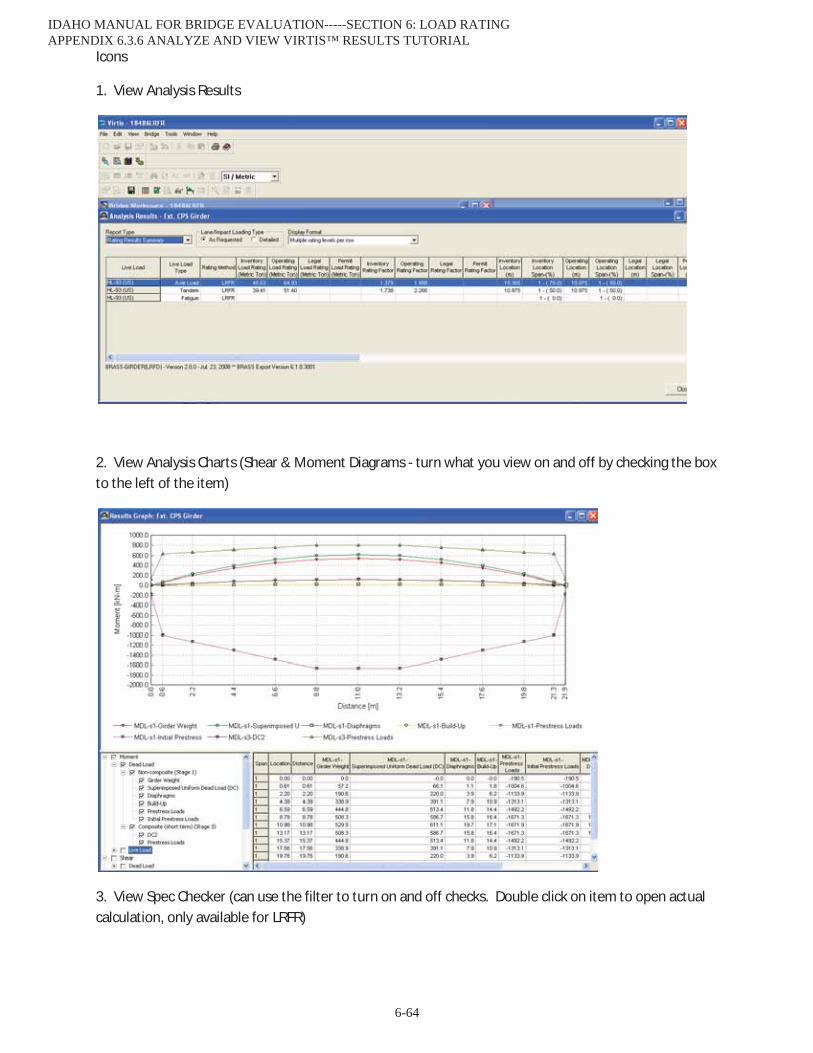
Icons
1. View Analysis Results
2. View Analysis Charts (Shear & Moment Diagrams - turn what you view on and off by checking the box to the left of the item)
3. View Spec Checker (can use the filter to turn on and off checks. Double click on item to open actual calculation, only available for LRFR)
IDAHO MANUAL FOR BRIDGE EVALUATION-----SECTION 6: LOAD RATING APPENDIX 6.3.6 ANALYZE AND VIEW VIRTIS™ RESULTS TUTORIAL
6-64
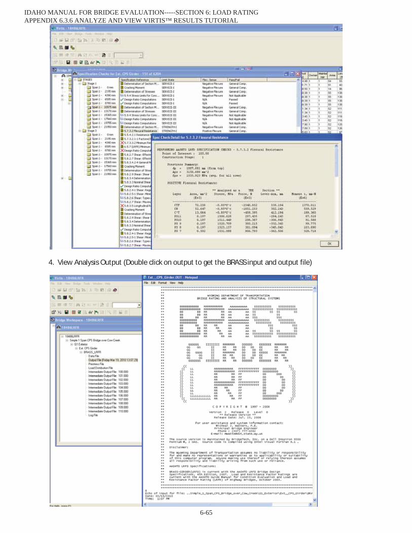
4. View Analysis Output (Double click on output to get the BRASS input and output file)
IDAHO MANUAL FOR BRIDGE EVALUATION-----SECTION 6: LOAD RATING APPENDIX 6.3.6 ANALYZE AND VIEW VIRTIS™ RESULTS TUTORIAL
6-65
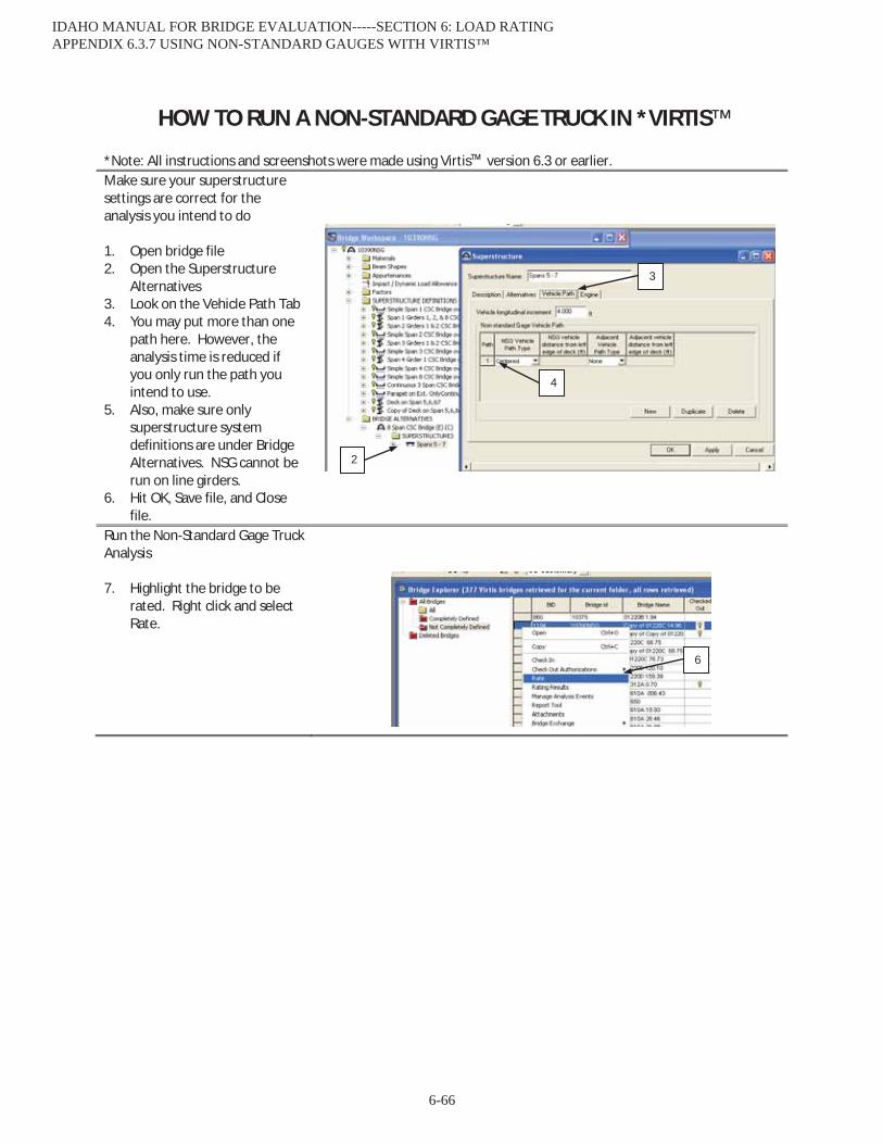
HOW TO RUN A NON-STANDARD GAGE TRUCK IN *VIRTIS™
*Note: All instructions and screenshots were made using Virtis™ version 6.3 or earlier. Make sure your superstructure settings are correct for the analysis you intend to do 1. Open bridge file 2. Open the Superstructure
Alternatives 3. Look on the Vehicle Path Tab 4. You may put more than one
path here. However, the analysis time is reduced if you only run the path you intend to use.
5. Also, make sure only superstructure system definitions are under Bridge Alternatives. NSG cannot be run on line girders.
6. Hit OK, Save file, and Close file.
Run the Non-Standard Gage Truck Analysis 7. Highlight the bridge to be
rated. Right click and select Rate.
4
2
3
6
IDAHO MANUAL FOR BRIDGE EVALUATION-----SECTION 6: LOAD RATING APPENDIX 6.3.7 USING NON-STANDARD GAUGES WITH VIRTIS™
6-66

8. The Analysis Settings window
will come up. Set the Rating Method to LFD. (NSG is not available for LRFD)
9. Set the Analysis Type to Advanced.
10. Select the vehicle you want to run from your Vehicle Selection list and move it to your Vehicle Summary list with the arrow buttons.
11. Set the Advanced Analysis Settings by clicking on the Advanced button.
12. When the advanced settings are correct click OK and then OK again to begin the NSG analysis. It may take several minutes depending on the complexity of the bridge and the truck.
7
8
9
10
IDAHO MANUAL FOR BRIDGE EVALUATION-----SECTION 6: LOAD RATING APPENDIX 6.3.7 USING NON-STANDARD GAUGES WITH VIRTIS™
6-67
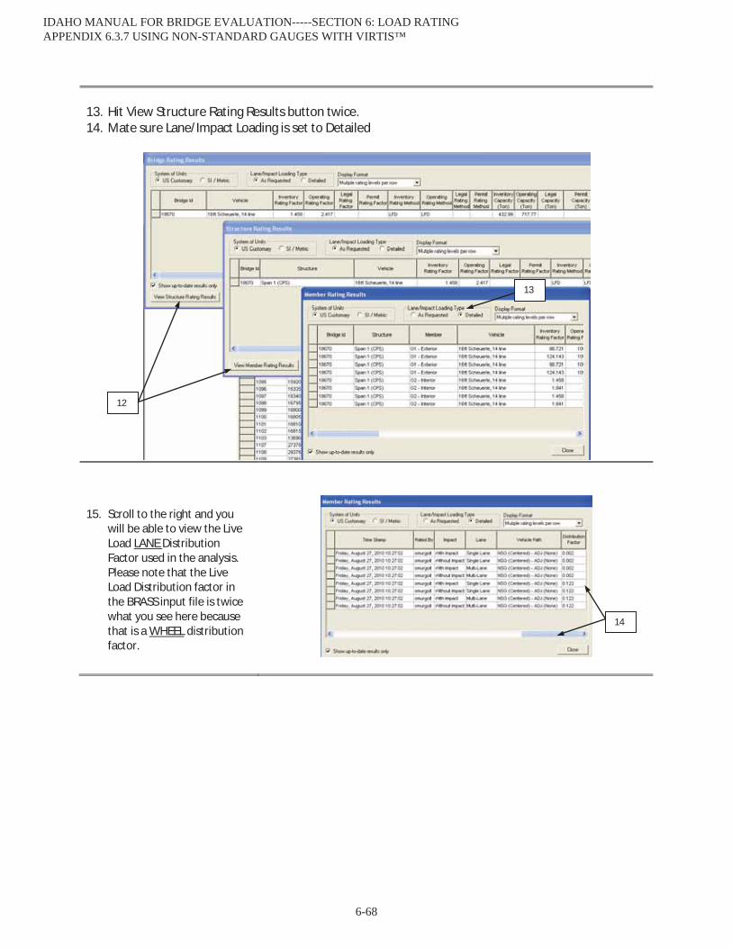
13. Hit View Structure Rating Results button twice. 14. Mate sure Lane/Impact Loading is set to Detailed
15. Scroll to the right and you
will be able to view the Live Load LANE Distribution Factor used in the analysis. Please note that the Live Load Distribution factor in the BRASS input file is twice what you see here because that is a WHEEL distribution factor.
12
13
14
IDAHO MANUAL FOR BRIDGE EVALUATION-----SECTION 6: LOAD RATING APPENDIX 6.3.7 USING NON-STANDARD GAUGES WITH VIRTIS™
6-68
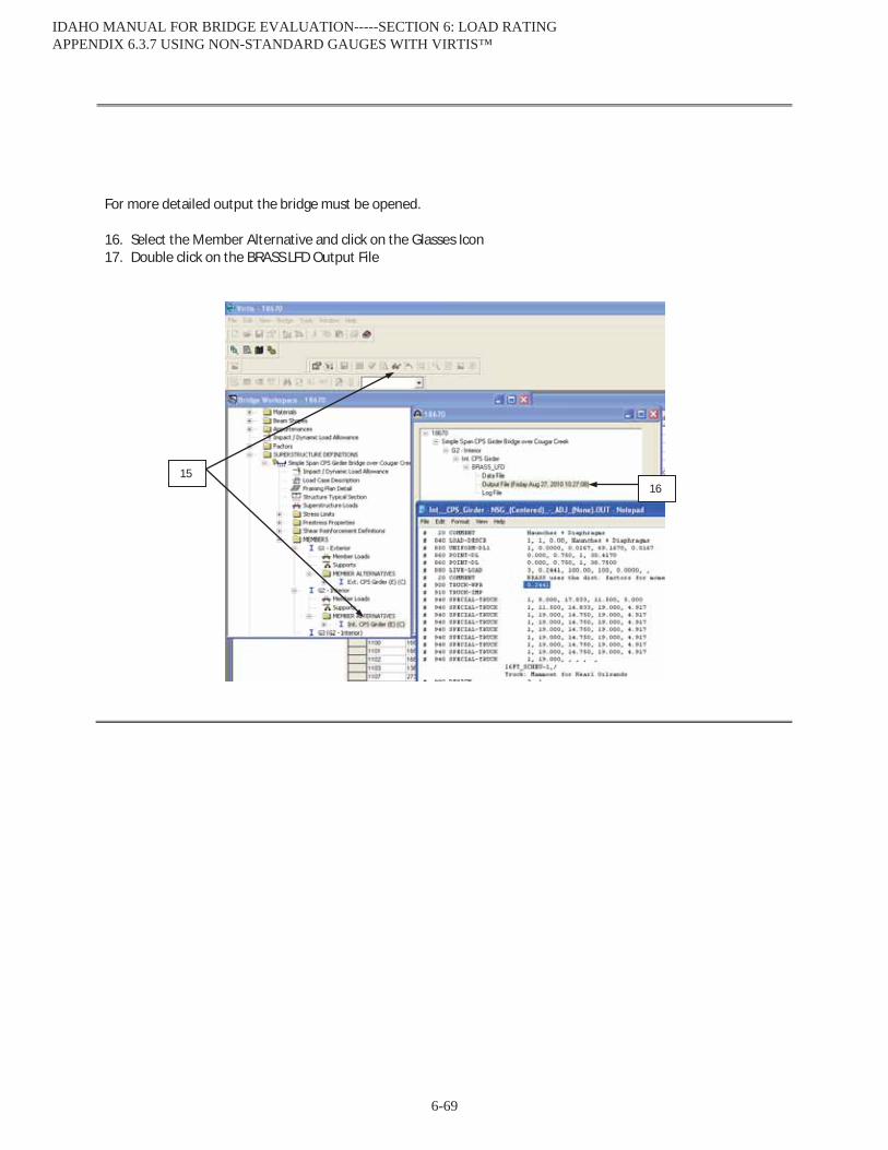
For more detailed output the bridge must be opened. 16. Select the Member Alternative and click on the Glasses Icon 17. Double click on the BRASS LFD Output File
15 16
IDAHO MANUAL FOR BRIDGE EVALUATION-----SECTION 6: LOAD RATING APPENDIX 6.3.7 USING NON-STANDARD GAUGES WITH VIRTIS™
6-69

Checklist for In-House Rehab Ratings that have an existing BrR™ file
Rater
� Make a copy of the “Completely Defined” BrR™ file that needs to be updated.
� Change the file from “Completely Defined” to “Not Completely Defined”.
� Make a copy of the Superstructure Definition(s) that needs to be updated and add year and rehab to the name(s). (Ex. Change “Span 1 CPS Girder Bridge” to “FY 2010 Rehab – Span 1 CPS Girder Bridge”
� Make the appropriate modifications to the copy of the Superstructure Definition.
� Make a list of the modifications made in the Description window on the Definition Tab of the Superstructure Definition window. Include the name and date of the person who made the modifications.
� Add the following sentence to the Description window on the Description tab of the Bridge Definition. “Modifications to file made by (name) on (date) for FY (year) rehab. See Superstructure Definition Description for details.”
� Change the Superstructure(s) listed under Bridge Alternatives to the modified Superstructure Definitions.
� Copy the existing Load Rating Summary Form stored under Y:\Load Rating\LRS_Calcs and paste it into Y:\Load Rating\LR Rehabs directory under a folder that’s name contains the bridge key. Copy and paste the information you added under to the Superstructure Definition into the Remarks section of the Load Rating Summary Form. (An engineering stamp is not required on an updated Load Rating Summary Form. Spreadsheet may need to be unprotected to edit.
� Put a pdf version of the rehab plans in the same directory as the Load Rating Summary Form
� Complete the appropriate cells of the RehabLoadRatingTracking sheet Y:\Load Rating\LR Rehabs\RehabLoadRatingTracking.xlsx
� Find someone to check the updated file if the updates are not limited to a deck rehab.
� When any comments the checker has are resolved, the rater shall send an e-mail to [email protected]. The Subject line of the e-mail should read “Ready for Q/C: (bridge key) rating updated for FY(year) Rehab”
Checker (only required for updates that are not limited to a deck rehab)
� The updated file shall be checked by someone who will add “Rehab revisions checked by: (name)(date)” in the Description window on the Definition Tab of the Superstructure Definition windowand under the Remarks section of the Load Rating Summary Form.
� Complete the appropriate cells of the RehabLoadRatingTracking sheet Y:\Load Rating\LR Rehabs\RehabLoadRatingTracking.xlsx
IDAHO MANUAL FOR BRIDGE EVALUATION-----SECTION 6: LOAD RATING APPENDIX 6.4.1 IN-HOUSE REHABILITATION RATINGS CHECKLIST
6-70