page 1 of 23 the owner of the edm-760/790 must keep …
TRANSCRIPT

Installation manual for the EDM-760 / 790Twin STC SA00729SE Report No. 760
Temperature indicating system with Fuel Flow Date 8-1-14 Rev B
Page 1 of 23
THE OWNER OF THE EDM-760/790 MUST KEEP THIS MANUAL TABLE OF CONTENTS
1. INSTALLING THE INDICATOR 2
2. EXHAUST GAS TEMPERATURE PROBE (EGT) 2
3. TURBINE INLET TEMPERATURE PROBE (TIT) 2
4. USE ORIGINAL TIT BY PIGGY BACKING ORIGINAL 2
5. CYLINDER HEAD TEMPERATURE PROBE (CHT), BAYONET 2
6. SPARK PLUG GASKET CHT PROBE 3
7. INDUCTION AIR/CARBURETOR TEMPERATURE 3
8. OIL TEMPERATURE PROBE 3
9. OUTSIDE AIR TEMPERATURE PROBE, OAT 3
10. FUEL FLOW OPTION 3
11. DATA PORT RS-232 OR DATA STORAGE 3
12. WIRING (12 / 24 VOLT) 4
13. EGT AND CHT PROBE WIRING MARKINGS 4
14. ROUTING THE WIRING HARNESS 4
15. INDICATOR INSTALLATION & RECORD 5
16. DESCRIPTION 5
17. OPERATION 7
18. EDM-760/790 SPECIFICATIONS AND LIMITATIONS 7
19. COMPONENTS PARTS LIST 8
20. WEIGHT AND BALANCE DATA 9
21. CHANGING THE PROGRAMMED LIMITS 9
22. TROUBLE SHOOTING 10
23. PANEL CUT OUT FIG – 1 12
24. MOUNTING BRACKET FOR EDM-790 13
25. EDM-790 LAYOUT 20
26. DWG 760202 21
27. FUEL FLOW WIRING FIG 9 22
28. INSTRUCTIONS FOR CONTINUED AIRWORTHINESS (ICA) 23
29. APPENDIX A FUEL FLOW TRANSDUCER INSTALLATION 23 J.P.INSTRUMENTS PO BOX 7033 HUNTINGTON BEACH CA 92615 Last printed 10/2/21

Installation manual for the EDM-760 / 790Twin STC SA00729SE Report No. 760
Temperature indicating system with Fuel Flow Date 8-1-14 Rev B
Page 2 of 23
REV Description Date Approval
A Added Rev box and corrected part No. 2-24-14 JFP
B Added 790 display 8-1-14 JFP
1. INSTALLING THE INDICATOR Installation Should Be Done In Accordance With Advisory Circular AC43.13-1A A steel template supplied with the installation kit is used as a guide for drilling two buttonholes in the instrument panel. Align and Mount the Template into the instrument panel hole. First drilling a 0.125 hole. Remove the template and check the instrument alignment, if OK re-drill with a 0.147 drill. The plastic buttons are removable by pulling off. The EDM-760/790 mounts in a standard 3.125" instrument hole. The instrument configures itself automatically for Twin 4 or 6 cylinder, 14/28 volt aircraft. The instrument is 7.5” deep less connectors and is 3.20 square behind the panel.. TO PREVENT DISPLAY DAMAGE IT IS ESSENTIAL THAT THE FOUR MOUNTING SCREWS NOT PENETRATE THE INSTRUMENT MORE THAN .12 INCHES. DAMAGE OF THIS NATURE IS NOT COVERED UNDER WARRANTY.
2. EXHAUST GAS TEMPERATURE PROBE (EGT) The Model M-111 Probe will fit any existing holes in the exhaust stack in any engine having the diameter of 1/8" to 1/4". If no hole exists, it will require the drilling of a 1/8" diameter hole and ream to fit. It is important that each probe be mounted a uniform distance from the exhaust stack flange. A nominal distance of 2 to 4 inches from the exhaust flange is recommended. (See fig-2). If the recommended distance is impractical because of obstructions, slip joints or bends in the exhaust system then position the probes a uniform distance from the flange as space permits. Do not mount probes in slip joints. Be certain to locate all holes BEFORE drilling to ensure that nothing interferes with the probe, clamp, and clamp screw or wire. Careful matching of probe position will provide best temperature readings. Insert the probe in the exhaust or previously drilled hole (see fig-3) so that the tip of the probe is in the center of the exhaust stream. Tighten the stainless steel clamp to a torque of 45 in/Lbs. Cut off the excess strap close to the screw.
3. TURBINE INLET TEMPERATURE PROBE (TIT)
The standard TIT probe P/N M-111 with a special clamp is placed in the exhaust stack accumulator to a maximum depth of 1/2 inch and approximately four (4) inches from the Turbine inlet if possible, on the wastgate side of the turbine. TIT will appear as the seventh column “T “and the expression “1650 TIT” will be seen when the dot is in place over it.
4. USE ORIGINAL TIT BY PIGGY BACKING ORIGINAL The EDM-760/790 input is compatible with the aircraft’s factory TIT and will not load the factory probe. Connect the EDM-760/790 TIT wire to the same red/yellow leads on the factory probe. Check calibration by running up the engine and noting if there is and difference between the factory reading and the EDM-760/790 reading. Note any difference and mark it down plus or minus. Then Hold the two buttons in and Program/Rate - 4 will display. Again hold the two buttons in and TIT +0 / ADJ. will appear. Tap the LF to subtract and hold to add. When the correct difference is displayed tap step to go to back to TIT reading. Reading should be close to correct, repeat as required.
5. CYLINDER HEAD TEMPERATURE PROBE (CHT), BAYONET
The Bayonet probe 5050-T has the 3/8-24 boss as part of the probe and is screwed into the base of the cylinder (See fig-2). The bayonet probe has a screwdriver slot to facilitate tightening.
NOTE: Required original equipment that has a Red Line may not be replaced by the EDM-760/790 TIT or CHT installation. This includes but is not limited to all aircraft with adjustable cowl flaps and on aircraft with placards on the instrument panel showing a climb air speed, for cooling, different from the best rate of climb air speed. If a previously installed TIT, CHT or EGT is not required for certification (or STC modification), it may be replaced by the EDM 760/790.

Installation manual for the EDM-760 / 790Twin STC SA00729SE Report No. 760
Temperature indicating system with Fuel Flow Date 8-1-14 Rev B
Page 3 of 23
6. SPARK PLUG GASKET CHT PROBE Most factory installed cylinder head temperature gauges utilize a bayonet or screw-in resistive type probe that occupies one of the bayonet sockets. This probe is not compatible with the thermocouple probes required for the EDM-760/790. The spark plug gasket probe, P/N M-113, replaces the standard copper spark plug gasket on one spark plug. The plug chosen, upper or lower, should be the one that provides the best correlation with the other temperature probes.
Due to the spark plug location, the gasket probe may read 25o
F higher or lower than the factory probe. The probe is usually placed under the plug that receives the most direct cooling air. After many removals the probe may be annealed for re-use. Heat and quench in water. At additional cost an adapter probe (bayonet) is available that permits the factory CHT probe and a JPI probe to fit the same bayonet location.
7. Induction Air/Carburetor Temperature Install P/N 130 Induction air/carburetor probe in the induction air housing or in the throat of the carburetor. Marvel carburetors have a ¼-28 threaded plug in the neck, remove and place the probe in that location.
8. OIL TEMPERATURE PROBE
The Oil Temperature Probe P/N 400505-C-L is installed as a supplemental oil temperature indicator. The -L part number is for all Lycoming Direct Drive Engines and is installed in the Right (passenger side) front Oil galley by removing the present 1/8 NPT plug (see fig-4). The -C part number is for all Continental Direct Drive engines and is installed in the Left (pilot side) front Oil galley by removing the present plug (see fig-5). Oil temperature will be displayed as an independent temperature like "230 OIL" and will be displayed In the seventh column automatically if TIT is not available. The original oil temperature gauge and sensor must remain. Check for oil leaks and safety wire before first flight.
9. OUTSIDE AIR TEMPERATURE PROBE, OAT
Install the OAT probe, P/N 400510 in the airframe manufactures recommended location. If this is not possible, it is recommended that the OAT probe be placed in clean airflow such as in a cabin air scoop or below the underside of the wing away from engine heat or exhaust. In this case it is recommended that the installation be done similar to the antenna installation instructions of AC 43.12-2a "Acceptable Methods, Techniques and Practices". The outside aluminum tube is used to both hold the probe in place and shield it from radiated heat. OAT option is displayed as an independent digital temperature like "75 OAT".
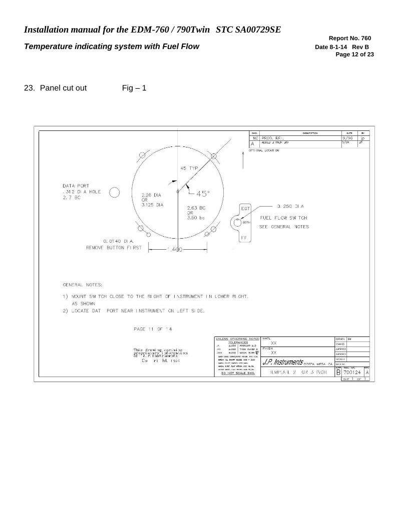
10. FUEL FLOW OPTION Install the Fuel Flow transducer FXT-201 in accordance with Appendix-A, report 760/790. The EDM-760/790 can receive signal from any fuel flow transducer that was previously installed by the OEM or by STC, the EDM-760/790 with Fuel Flow option can share the transducer signal, specifically the FlowScan P/N 201-B or the Shadin PN 680501X / 680600X transducer. Wire per drawing 760/790744 and route the JPI wires along the existing wiring bundles lacing every foot. Install the Function switch per drawing 760/790124.
The placard "Do Not Rely on Fuel Flow Instrument to Determine Fuel Levels in Tanks" (PN 700905) must be mounted on the
aircraft instrument panel near the EDM-760/790 with fuel flow option.
If the aircraft is equipped with a primary fuel flow, the following placard must be mounted on the aircraft instrument panel
near the EDM-760/790, WITH FUEL FLOW OPTION: "Refer to Original Fuel Flow Instrumentation for Primary
Information". (PN 700905)
11. DATA PORT RS-232 or DATA Storage Data output is a line of data every 6 seconds at 9600 Baud. This data can be captured by any palmtop or laptop computer through the COM port in the modem receive mode or stored in memory and down load at a later time. Set modem to 9600 Baud, no parity and 1 stop bit. JPI also offers a program that will make it easier to load the data that can be converted into a Lotus or Excel format. JPI’s program is IBM compatible. Mac Computers loading through the Com/modem method.

Installation manual for the EDM-760 / 790Twin STC SA00729SE Report No. 760
Temperature indicating system with Fuel Flow Date 8-1-14 Rev B
Page 4 of 23
12. WIRING (12 / 24 volt) The EDM-760/790 automatically accommodates both 14 and 28-volt electrical systems. Using the 15 pin connector, connect the power lead (red) to a separate 2 amp circuit breaker (or 2 amp in-line fuse) connected to the avionics power buss. The avionics master switch will then be used to turn off the instrument during engine start-up. The EDM-760/790 has a 10-second warm-up. If the panel lacks an avionics master switch we recommend that one be installed or a pull circuit breaker switch be provided to turn off the EDM-760/790 during engine start-up. No connection to the aircraft dimmer system is required because the instrument dims automatically with reductions in ambient light. A fully assembled harness is supplied with 21ft t/c leads.
13. EGT and CHT Probe Wiring Markings The EDM-760/790 is supplied with special Teflon insulated Chromel Alumel factory assembled wiring harness configured for the correct number of cylinders. The wire harness is marked (E-1= EGT-1), (C-1= CHT-1), etc. TIT is marked “T”, Oil Temp = “O” and OAT = “A”. NOTE: Unlike most other EGT & CHT installations the probe wire length is not critical and should be trimmed to any length as required for a clean installation. The Temperature probes must be wired with the correct polarity. Each wire is marked with the cylinder number. The EGT and CHT probes connect to the temperature indicator with yellow jacket Teflon Chromel Alumel wire supplied. Strip the wires according to drawing 5057 and terminate with the crimp-on ring terminals provided. Verify the quality of each crimp with a sharp pull on the wire. The terminal should be almost impossible to pull off when crimped correctly. With in a few inches of the instrument terminal strip a connector may be installed. NOTE: The ring terminals may be crimped with a " service type " tool, however AMP part number 48518 tool is recommended. Be sure to test each crimp by pulling on the wire to assure it will not come out. The most common installation problems are poor quality terminations.
14. ROUTING THE WIRING HARNESS Route the thermocouple wires from the probes through the firewall using fireproof rubber grommets and flame retarding silicone. Use an existing hole if possible. Following the existing wiring harnesses and connect to the indicator marking each lead with the cylinder number. All wires must be routed away from high temperature areas (exhaust stacks, turbochargers, etc.). Secure Probe leads to a convenient location on the engine approximately 8 to 12 inches from the probe, being sure there is sufficient slack to absorb engine torque. It is essential in routing the probe wire that this wire not be allowed to touch metal parts of the airframe or engine since abrasion will destroy this high temperature wire. Secure thermocouple wires along the route to the indicator. Secure wire using original clamps, tape or tie wrap if possible.
CAUTION: Be sure the controls under the panel are not obstructed by the wiring.
Run up the Engines and confirm that the right engine is displayed on the right indicator and the left engine is displayed on the Left indicator of the EDM-760/790 display. The probe wires must not be tied in with ignition, alternator or twin engine cabin heater ignition wires because of potential interference with temperature readings. The probe wiring harness is made of Chromel-Alumel alloy wire that must not be substituted or extended with normal copper wire. The power and ground wire are normal copper. Leads may be spliced with additional Chromel-Alumel wire using copper butt splices. When the installation is complete all wires should be secured using ties and carefully checked for interference, rubbing or chaffing with flight control cables or other moving parts.

Installation manual for the EDM-760 / 790Twin STC SA00729SE Report No. 760
Temperature indicating system with Fuel Flow Date 8-1-14 Rev B
Page 5 of 23
15. INDICATOR INSTALLATION & RECORD Locate a 3.125” diameter hole in the instrument panel, where you would like to mount the indicator per drawing 760/790124. Mount the indicator in the panel, using the four 6-32 X.0.15" screws. The screws must not penetrate the bezel more than .120". Three connectors are protruding from the rear of the instrument. Two 25 pin and one 15 pin connector. The top 25-pin connector connects the left engine harness. The bottom 25-pin connector, connects the right engine harness and the center 15-pin connector, connects the power and options like OAT.
Record the installation of the EDM-760/790 on a FAA form 337. Make entry in the aircraft logbook.
16. DESCRIPTION GENERAL The EDM-760/790 temperature indicator displays temperature digitally and in analog format. The analog display is an electronic bar graph of EGT & TIT temperatures presented as a percentage of 1650oF. Below the vertical columns the specific value for EGT and CHT are displayed digitally for both engines. EGT top and CHT bottom. The dot over the column indicates which cylinder's digital information is presently displayed. The missing bar in the graph represents the CHT trend, showing which cylinder is hotter or cooler and is checked digitally. Depressing the LF and STEP button simultaneously brings up the Pilot Programmable Mode in which the scan rate, OAT, and EGT resolution can be adjusted. Exit by Depressing STEP. If the EDM-760/790 buttons are not depressed for 1 minutes the system will start scanning automatically. Depressing the STEP button will stop the automatic scan and index through all the functions available. During cruise, if the LF button is depressed for five seconds (normalize mode) the bar graph will level at mid scale. The leveled bars represent the peaks of each column. Each bar represents 10oF and now acts as an EGT & TIT trend monitor, quickly showing an increase or decrease in temperature. Depress again to return too normal; nothing else is affected. TIT, OAT, OIL, BAT (voltage), Fuel flow functions and CLD (Rate of change of CHT in degrees per minute) are displayed digitally with headlines after the temperature, such as "230 OIL". A large value of "CLD" indicates shock cooling which has a detrimental effect on the engine and is usually associated with rapid descents at low power. Probes not installed will not be displayed.
An alarm causes the digital function to flash when the particular limit is reached. Factory generic set alarm limits for example: CHT (450 oF) and OIL (230 oF) are lower than the actual aircraft limits. The values may be adjusted to individual aircraft limits by pressing the reset button located on the rear of the instrument. Other factory set alarm limits are: "BAT" Voltage 15.5/12.0 or 31.0/24.0 Hi/Lo as appropriate; "DIF" (differential Hi/Lo EGT) 500 oF; "TIT" 1650 oF Hi; "OIL" Lo 90
oF; "CLD" (Rate of change of cylinder head temperature in degrees per minute) -60 degrees/minute. An alert output is available for the above functions that will sink 250 ma load. The pilot should be aware of the setting of each alarm for his particular aircraft. All alarms are "Canceled" in two ways: One by tapping the step button which will remove the alarm for 10 minutes. The second way is by holding the step button in for 5 seconds and seeing the word "OFF". Then, only that particular alarm is canceled . Canceled alarms will not appear again until the power has been removed and reapplied to the EDM-760/790. The entire display dims automatically depending on the ambient lighting. EDM-760
14)
Alarm limits set for this
instrument if different from
JPI limits.
CHT__________
OIL__________
TIT__________
DIF__________
CLD__________
BAT__________
TECH_________ DATE_________

Installation manual for the EDM-760 / 790Twin STC SA00729SE Report No. 760
Temperature indicating system with Fuel Flow Date 8-1-14 Rev B
Page 6 of 23
EDM-790 Display

Installation manual for the EDM-760 / 790Twin STC SA00729SE Report No. 760
Temperature indicating system with Fuel Flow Date 8-1-14 Rev B
Page 7 of 23
EDM-760/790-6CT With the fuel flow option a three-position mode (toggle) switch is installed in the panel per drw. 760124. The mode positions are: 1) EGT, digital and Bargraph display of temperatures, 2) FF., digital display of GPH, REM, REQ and fuel USED. Temperature Bargraph remains. 3) Both, cycles through everything installed. The data port output, sends RS232 serial data every 6 sec. A second alert output is available for the above functions that will sink 250-ma load. See drawing 760701 for wiring details.
17. OPERATION Airplane flight manual limitations based on primary instrument indication take precedence over those of the EDM-760/790.
CAUTION Comply with manufacturer's Airplane/Rotor craft
Flight Manual leaning procedure. Do not exceed applicable engine
or aircraft limitations. After establishing desired cruise power depress the LF button to activate the Lean Find Mode. The pilot should start leaning one engine. The EDM-760/790 is waiting to see which engine starts to increase in temperature, using that engine as the engine being leaned. At this time the hottest cylinder is displayed, as a reference, along with fuel flow per hour. As the mixture is leaned, a column on the EDM-760/790 will begin blinking, indicating the exhaust gas temperature for that cylinder has peaked. Continue with the leaning procedure as recommended by the aircraft manufacturer while monitoring the primary engine instruments and the EDM-760/790 display. Depressing the LF button while the column is flashing will show the peak digital EGT value. Once the leaning procedure has been completed, depress the Step button briefly to exit the Lean Find Mode and enter the Monitor Mode. If you have the fuel flow option installed, set the mode switch to FF to monitor fuel burned per hour, fuel used, fuel remaining, and if the EDM-760/790 is connected to a GPS, fuel required to next way point is displayed. When the EDM-760/790 is first turned on with the fuel flow option, it will ask if you have filled the tanks (Tank size preset) or how much fuel was added. If no response to fuel question in 5 minutes, system will assume no fuel added.
18. EDM-760/790 SPECIFICATIONS and LIMITATIONS FACTORY LIMITS EGT (Exhaust Gas Temp.,K ,Max. limit 2500 oF) 1650 oF CHT (Cylinder Head Temp., J/K Max. limit 600 oF) 450 oF TIT (Turbine Inlet Temperature, K, Max. limit 2500 oF) 1650 oF TIT-2 (Turbine Inlet Temperature, K, Max. limit 2500 oF) 1650 oF OIL (Oil temperature if not TIT-2, K, Max. limit 600 oF) (Hi/Lo) 230/90 oF OAT (Outside Air Temp., K, Limit -40 to 300 oF) CLD (Rate of change of CHT) -60 o/minute DIF (Maximum EGT differential) 500 oF BAT (Voltage, 0 to 40 volts.) 15.5/12.0 or 31.0/24.0 Hi/Lo GPH (in Gal, lit, lbs, per hour) Fuel flow does not comply with TSO-C44 USD (Fuel Used) (999.9 gal. 9999 L/Lbs/Kg) Low alert: fuel=10 gal. REM (Remaining in Hours and minutes) Low alert: Time= 45 min REQ (Required to dest., GPS format NMEA 183/Binary/Aviation.) No limit Operate and lean the engine in accordance with the manufacturers' recommendations for different power settings. Lycoming recommends running peak EGT only at 75% power or less. Continental recommends running peak EGT at 65% power or less.

Installation manual for the EDM-760 / 790Twin STC SA00729SE Report No. 760
Temperature indicating system with Fuel Flow Date 8-1-14 Rev B
Page 8 of 23
19. Components Parts list
19.1 Component Parts List for EGT (PN 1280) ,TIT (PN 1200) Probe in polybag
Thermocouple type K probe Stainless Steel Clamp Thimble Stainless Steel Exhaust Seal Washer Stainless Steel Screw Type Clamp Ring Terminals Screws and nuts 6-32 X 1/4 Fiberglass tube 1/2" X 4"
19.2 Component Parts list for CHT (PN 1260) probe
Bayonet Probe Thermocouple type K Spring loaded Or Gasket thermocouple probe type K Ring Terminals Screws and Nuts 6-32 X 1/4" Fiberglass tube 1/2" X 4"
19.3 Components Parts list for OIL (PN 1240) probe
P/N 400505 -C or -L, OIL probe Ring Terminals Screws and Nuts 6-32 X 1/4" Fiberglass tube 1/2" X 4"
19.4 Components Parts list for OAT ( PN 1220) probe
P/N 400509, OAT probe Ring Terminals Screws and Nuts 6-32 X1/4" Fiberglass tube 1/2" X 4"
19.5 Components Parts list for CARB ( PN 1190) probe
1 P/N 400128, CARB probe 2 Ring Terminals 2 Screws and Nuts 6-32 X1/4" 1 Fiberglass tube 3/8” x 5”
19.6 Components Parts list for RPM
Bendix magneto series 20,21………………….…P/N 420806 Bendix magneto series 1200,………………..…...P/N 420807 Bendix magneto Plug Std ………….………..…...P/N 420815-1 Bendix magneto Dual…………………………..….PN 420808 Slick magneto series 4000 or 6000 P/N 420809 or Plug PN 420815-2 Slick magneto Plug Std…………………………….PN 420815-1
19.7 Components Parts list for IAT ( PN 1120) probe
1 Thermocouple type K probe PN M-111

Installation manual for the EDM-760 / 790Twin STC SA00729SE Report No. 760
Temperature indicating system with Fuel Flow Date 8-1-14 Rev B
Page 9 of 23
1 Stainless Steel Clamp &Thimble
1 Stainless Steel Exhaust Seal Washer
19.8 Component Parts list for Twin Engine, EGT and CHT
P.N. 760/790000 -4C -6C Temperature Indicator 1 1
EGT probe KIT PN 1280 4 6
CHT probe KIT PN 1260 6 6
Oil probe with option O KIT 1240 1 1
TIT probe with option T KIT 1200 1 1
OAT probe with option A KIT 1220 1 1
IAT probe with option I KIT 1300 1 1
RPM one of P/N 420806, 7, 9, 15-1,-2 1 1 TC Harness PN 700702 1 0
TC Harness PN 700750 0 1
TC Harness PN 700709 1 1
TC Option wire PN 700201 0 0
20. Weight and Balance Data Temperature Indicator EDM-760/790 1.12 lb. EGT probe MM-111 2.0 oz. each / 0.125 lb ea. CHT probe 5050 1.5 oz. each / 0.094 lb. ea. One Harness 20 ft for 6 cylinder. Each 2.0 lb. ea. One Harness 20 ft for 4 cylinder. each 1.12 lbs ea. Fuel Flow Transducer .2 lbs
21. CHANGING THE PROGRAMMED LIMITS The programmed limits are changed by pressing the reset button in the back of the instrument when the power is on or going into pilot program mode and at the end press STEP and LF simultaneously. The STEP button indexes alarms. The LF button changes the limits by holding in to advance and tapping to back up the value. The following messages and JPI set limits will appear: "FAC LIM" (Bold headings will display for 2 seconds only) "FAC ? N" (N=NO Y=YES) Yes.... Reinstalls the generic alarms and will also reset the automatic configuration sequence. It is necessary to say yes if an option was placed in the wrong connector location. or the instrument is not displaying certain options. “Type K” "VER 002" (Software Version)
"ENG F" (All Engine temperatures in oC or oF ) If oC is chosen, then ALL alarm Limits must yes-no be manually reset to oC values "BATTERY" "15.5H BAT" (High Voltage Limit - or 31.0vdc) "12.0L BAT" (Low Voltage Limit - or 24.0vdc)
"EGT DIF" "500 DIF" (Difference between highest and lowest EGT)
"CHT HI" "450H CHT" (Cylinder Head Temperature limit)
"COOL CHT" "- 60 CLD" (Cool Rate Limit, calculated in degrees per minute for cooling only)

Installation manual for the EDM-760 / 790Twin STC SA00729SE Report No. 760
Temperature indicating system with Fuel Flow Date 8-1-14 Rev B
Page 10 of 23
"TIT HI" "1650 TIT" (Turbine Inlet Temperature Limit)
"OIL TMP" "230H OIL" (High Oil Temperature Limit) " 90l OIL" (Low Oil Temperature Limit)
“TIT2 -N (If TIT2 probes are not installed in place of oil probes)
K-FACTOR left engine ( Set transducer K factor for example 29.90) K-FACTOR right engine ( Set transducer K factor) FUEL FLW Chose GAL, KGS, LTR, LBS or KGS. MAIN / AUX TANK (Set size in what ever units chosen above) LOW TIME (Set time in standard minutes) Low=45 min LOW FUEL (Set Quantity in units selected) Low=10 gal
CARB ? N (Y yes carbureted, N no fuel injected) changes time constant
MIN DISP (Changes maximum dimness level 0 to 31)
"END Y"
22. TROUBLE SHOOTING A missing column in the display upon start up indicates the continuity check diagnostic routine has found an open line or probe with no connection. An error message will indicate which cylinder to look at. A missing column in the display during flight indicates a reading that is jumping around or incorrect. The probe is removed from the line up to prevent false alarms. A negative reading (-) in front of the number indicates reverse polarity on the red/yellow wire to probe. Using an Ohm meter or continuity checker measure across the probe output leads. A good probe should be around 2- ohms and at the connector to the probe around 20 ohms. Having problems with one cylinder reading ? Swap the suspected probe with a probe from a good cylinder. If the problem goes to the good cylinder the probe should be replaced. If the problem remains the same, it is in the Thermocouple hook-up wiring from the probe to the instrument or it can be in the ring terminals crimped to the wire. Remember to double back on the wire going into the ring terminal. Display jumps when transmitting on the radio. Review fig-6, a kit is available to stop transmission noise it connects on pin 11 connector P-1, (mike key button). EGT, large span. Normally aspirated (carburetor) engines at normal cruise display a “DIFF” of 125 to 175 oF spread between cyls. Injected engines at normal cruise display a “DIFF” 50 to 90 oF spread between cylinders. All cylinders are measured by a common circuitry. It is impossible not to have identical calibration on all channels. If the temperature is changing more than 500 F in one second it should not be trusted and a lose wire crimp or probe should be suspected. All EGT or CHT readings seem to High or Low or Unsteady. Use a DVM (digital voltmeter) to measure the difference between 760/790 SCANNER ground and the engine block ground. If the difference is greater than 0.5 volts with the alternator charging. Then remove the EDM-760/790 ground (Black wire) from the instrument panel and connect it directly to the ENGINE BLOCK for GROUND. OAT readings off by 25 degrees, but oil and CHT readings OK, look for copper wire spliced in line to OAT probe. OAT reading can be fine tuned +/- 5 degrees, see reset procedure. Engine heat could also be the cause.

Installation manual for the EDM-760 / 790Twin STC SA00729SE Report No. 760
Temperature indicating system with Fuel Flow Date 8-1-14 Rev B
Page 11 of 23
Gem conversion, CHT’s read high (100 degrees) EDM-760/790 not calibrated for Gem installation “J” calibration, return to factory. Copper Wire can not be substituted for thermocouple wire at any point. Unreliable Fuel Flow readings high will display as dashes, low will display zero. START UP ERROR LIST and PROBE LOCATION
Display indicates "OPEN PRB" then the following message on the engine side of the display: EGT 1 CHT 1 OIL EGT 2 CHT 2 OAT EGT 3 CHT 3 TIT 1 EGT 4 CHT 4 TIT 2 EGT 5 CHT 5 EGT 6 CHT 6
Installation manual for the EDM-760 / 790Twin STC SA00729SE Report No. 760
Temperature indicating system with Fuel Flow Date 8-1-14 Rev B
Page 12 of 23
23. Panel cut out Fig – 1

Installation manual for the EDM-760 / 790Twin STC SA00729SE Report No. 760
Temperature indicating system with Fuel Flow Date 8-1-14 Rev B
Page 13 of 23
24. Mounting bracket for EDM-790
Mounting bracket for the EDM-790
EDM-790 Model: Mounts in a standard 3.1/8” instrument hole. First place the mounting bracket on the instrument and tighten the clamp hex screw until you can just remove the instrument from the bracket. The Mounting bracket is then placed behind the instrument panel hole and screwed (6-32 x ½” screws) in place using the existing holes. Three screws should be used leaving one hole vacant on either side of the hex screw. Locate the hex screw in a location that you can easily get to from the rear of the panel. The body of the instrument is 3.0 inches and 2.0 inches deep less connectors.

Installation manual for the EDM-760 / 790Twin STC SA00729SE Report No. 760
Temperature indicating system with Fuel Flow Date 8-1-14 Rev B
Page 14 of 23
Filg-2

Installation manual for the EDM-760 / 790Twin STC SA00729SE Report No. 760
Temperature indicating system with Fuel Flow Date 8-1-14 Rev B
Page 15 of 23
Fig-3

Installation manual for the EDM-760 / 790Twin STC SA00729SE Report No. 760
Temperature indicating system with Fuel Flow Date 8-1-14 Rev B
Page 16 of 23

Installation manual for the EDM-760 / 790Twin STC SA00729SE Report No. 760
Temperature indicating system with Fuel Flow Date 8-1-14 Rev B
Page 17 of 23
IO-360/520
Std oil portboth sides
Alt location
Alt location
0-470
CONTINENTAL ENGINE OIL PROBE ALTERNATE LOCATION
Fig 5

Installation manual for the EDM-760 / 790Twin STC SA00729SE Report No. 760
Temperature indicating system with Fuel Flow Date 8-1-14 Rev B
Page 18 of 23
Fig 6

Installation manual for the EDM-760 / 790Twin STC SA00729SE Report No. 760
Temperature indicating system with Fuel Flow Date 8-1-14 Rev B
Page 19 of 23

Installation manual for the EDM-760 / 790Twin STC SA00729SE Report No. 760
Temperature indicating system with Fuel Flow Date 8-1-14 Rev B
Page 20 of 23
25. EDM-790 Layout same as EDM-900
Installation manual for the EDM-760 / 790Twin STC SA00729SE Report No. 760
Temperature indicating system with Fuel Flow Date 8-1-14 Rev B
Page 21 of 23
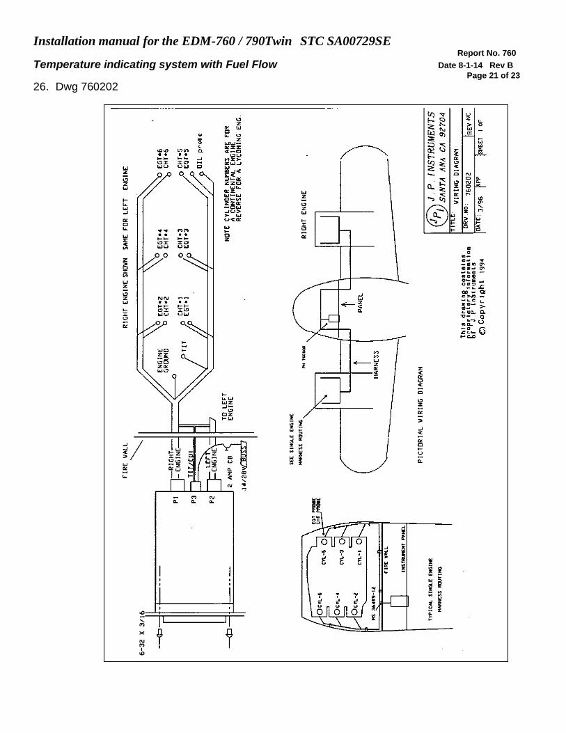
26. Dwg 760202

Installation manual for the EDM-760 / 790Twin STC SA00729SE Report No. 760
Temperature indicating system with Fuel Flow Date 8-1-14 Rev B
Page 22 of 23
27. Fuel Flow wiring Fig 9

Installation manual for the EDM-760 / 790Twin STC SA00729SE Report No. 760
Temperature indicating system with Fuel Flow Date 8-1-14 Rev B
Page 23 of 23
28. Instructions for Continued Airworthiness (ICA)
There are no field adjustments and or calibration requirements for the EDM-700 series instrument
after initial installation. ICA is not required. Maintenance of nonfunctioning or malfunctioning components is limited to removal and replacement of JPI factory supplied new or repaired
components as described in the troubleshooting section of the installation instructions
29. Appendix A Fuel Flow Transducer Installation