padsj. - everyspec.comeveryspec.com/mil-specs/mil-specs-mil-p/download.php?spec=mil-p... ·...
TRANSCRIPT

i[41L-P-2845C [SHIPS)15 March 1974SUPERSEDINGMIL-P-002845B (sH1PS)9 March 1973 andNIL-P-2845A2 J“ll, 1966(see 6.6)
I.IILITARY 5PECIFICATION
PACKI,G1:<C OF 1!-1111PRoPULS1ON SIIAFTING, BEAR1lIGS, BOAT AND SHIP
Pl<OPELLERS , AND ASSOCIATED REPAIR PARTS
Tl,is specification is approved for use by all Departments and Agencies of the Depart-ment of lJefense.
1. SCOPE
1.1 sco e. This specification covers the cleaning, drying, preservation-packaging,packing .n&):ing of main propulsion shaftinq, line shaft beari”qs, stern tube and stzutneari”qs, boat and ship propeller. (exclusive of controllable pitch propellers or shaftingfor controllable pitci, propellers) , and associated repair parts and tools. It also covers
cleaning, drying, preservation-Packag in9, packin9 .nd m=.rki.9 Of independently mOunted ~in
prOpulsiOn thrust Learinqs.
2. ,APPLICABLE DoCU14ENTS
2.1 The following doc”rnents of the issue in effect 0. date of invitation for bids orrequest for proposal, form a part of tbe specification to the extent specified herein.
SPEC1P1CATIONS
FEDERALNN-P-530 - Plywood, Flat Panel.TT-W-571 - Wood Preservation; Treating Practices.TT-W-572 - Wood Preservative; Water Repellent.PPP-B-566 - Boxes, k’oldinq, Paperboard.PPP-B-585 - Boxes, wood, Wirebound.PPP-B-591 - Boxes, Fiberboard, wood-cleated.PPP-B-601 - Boxes, liood, Cleated-Plywood.PPP-B-621 - Boxes, Wood, Nailed a“d I.ock-Corner.PPP-D-63G - km.., Shipping, Fiberboard.PPP-B-640 - Uoxes, Fiberboard, Corrugated, Triple-Wall.PPP-B-665 - Boxes; Pap.xboard Metal Stayed (I”cl”di”g Stay M.?.terial).PPP-B-67G - Iloxcs, Setup.PPP-B-1055 - Barrier Material, waterproofed, Flexible.PPP-c-650 - crates, wood, open and covered..PPP-C-343 - Cushio”i”g, liaterial Cellulosic.rPP-c-1120 - Cushioning !Iaterial, Uncompressed Board Fib.. for Packaging.PPP-’I’-6O - TaPe, Pressure-Sensitive Adhesive, waterproof, for Packaging.PPP-T-75 - ‘rape, Preservation a“d sealing.
MILITARYIM1L-C-104 - crates, wood, Lutier and Plywood sheathed, Nailed and Bolted.MI L-P-116 - Prescrvatio”, Methods of.;IIL-LI-121 - Barrier Material, Greaseproofed, Waterproofed, flexible.1111.-U-197 - Beari”Iv5, Anti-Friction, Associated Parts and S“b-As. eIrblies,
Packaqi”g of.FIIL-13-233 - Box.. , Repair Parts, storage.MI L-2-3106 - Board. Com.ositio”, Water-nesistant, Solid [Filler or C“shioninq
Padsj.)IIL-C-3774 - crates, wood, Open, 12,000 a“d 16,000 Pound capacity.MIL-R-5001 - N“bbe,, cellular $heet, Molded a“d Hand B“ilt shapes; Latex
l~oar.1.MIL-R-6130 - K“bber, cellular, chemically Blown.
MIL-C-C799 - Co,,tinq, , spray able, stripp~ble. prO*ective, water Eylsio..!UL-C-9897 - Crate, Slotted A“gle, steel or Al”min.m, For Lightweight Air-
frame cornpo”c”ts And D“lky Items (For t.raximum Loads of 3000Po””ds) .
FSC PACK
Downloaded from http://www.everyspec.com
~L-P-2845c (SHIPS)
MILITARY [cent Vd. )H1L-L-10547 - Liners, Case, and Sheet Gverwrap: Water-vaporproof or Water-
proof, Flexible.MIL-B-13239 - Barrier Material, waterproofed, Flexible, All Temperatures.MI L-C-16173 - corrosion Preventive Compound Solvent Cutback, Cold-Application.MIL-R-20092 - Rubber Sheets and Molded shapes, cellular, Symtbetic open cell
(Foamed Latex). @MIL-F-22191 - Barrier Materials Transparent, Flexible, [[eat Sealable.MIL-C-23760 - coating, Spray able, Strippable, Protective, F.. Preservation,
and Packaging of Weapons Systems and components, Applicationof.
MIL-C-26861 - Cushioning Material, Ilesilit?nt Type, General.NIL-C-46842 - Cushioning Fkaterial, unicellular Polyethylene Foam (For Pack-
aqinq Purposes) .MI L-T-50036 - Talc, Technical, T1.
STMIDARDS
MILITARYMI L- STD-105 -MIL-STD-129 -MIL-STD-731 -MIL-STD-758 -
MIL-STD-1186
Samplinq Procedures and Tables fo. Inspection by Attributes.Maxking for Sbipme. t and Storaqe.C!uality of Wood Members for Containers and Pallets.Packaging Procedures for Submarine Repair Parts, utilizingTransparent, Flexible, Heat Sealable Film.
- cushioning, ?u@oring, Bracing, Blocking and Waterproofing,Nit], Approp.zate Test Methods.
)IAVSHIPSNY-9-800-B-2095021 - Propeller Air-Lift Fzame.
[Application for copies should be addressed to commander, Mare Island Naval Sbipya.d(Code 564 B), Vallejo, California 94592. )
PUBL1CATION
NAVSHIPSMANUAL 0900-028-3010 - Manual for the Inspection, Packaginq a“d storage of
Sbipborne Hull, Mechanical; Electrical and Elect.o”iclkq. ipme”ts.
(Copies of specifications, standards, drawings, and publications required by Suppliersin co””e. tion with specific procurerte”t fu”ctio”s should be obtained from the procuringactivity or as directed by the contracting of ficer. ) o
2.2 ~ “blications. The following documents form a part of this specification to~ “nlessothewise indicated, theissue ineffecto” date ofthe extent speci led l,ereln.
invitation for bids or req”e.sts for proposal shall apply.
ASSOC1ATION OF Af4ER1CAN RAILROADSAssociation of American Railroads Rules
(Applicatim for copies should be addressed to the Association of American Railroads,59 E. Van B“re” Street, Cbicaqo, Illinois 60606. )
DEPARTMENT OF COMP!ERCECS-35 - I[ardwood Plywood.PS-1 - Softwood Plywood, Construction and I“d”strial.
(Application for copies should be addressed to tbe Superintendent of Documents, U. S.Government Printing Office, Washington, U.C. 20402. )
ut~xFOM c~551F1cAT10N COMJIITTEEUniform Freiqht Classification Rules
(Application for copies should be addressed to tbe U“iforzn Classification Committee,Room 1106, 222 South Riverside Plaza, Chicago, Illinois 60606. )
2
Downloaded from http://www.everyspec.com

MIL-P-2845c [SHIPS)
(Technical society and technical association specifications and standards are generallyavailable for reference from libraries. They are also distributed amonv technical groups
●and using Federal agencies. )
3. REQUIREMENTS
3.1 Fixst article san le. Prior to bqinninq production, a sample shall be examined~. Detailed test res.lts of thero.gh handli”gtests, whe”a“d tested as speclf, cd Ln
performed (see 4.2.1.2.1), sl,all be forwarded to the procurinq activity.
3.2 Materials. Material. shall be as specified herein, and in accordance with theapplicable speclfkca><
3. 2.1 New materials.
3.2.1.1 The use of newly developed preservation-packaging materials and procedures isencouraged and recormne”decl a“d will be permitted under the conditions specified herein,
provided they are equal tO or better than tile specified materials and procedures withOutincreased cost to the Government.
3.2.1.2 W“ere the material or procedure is “ok covered by’ a specific government docu-ment, the rnanufa. t”rcr or fabricator shall furnish to the procuring activity documented evi-dence tbat, the proposed material o. procedure is equal to or exceeds the requirements of thespecification for the material or procedure. If after a review of the documented evidence,it is the opinion of the procuring activity that tin. proposed material or procedure meetsor exceeds the criteria established for required materials or procedures, authorization foruse will be granted.
3.3 Pzeservatio”-pack aqin T. Preservation-packaginq shall be level A or level C, a.specified I.e. 6.2).
3.3.1 level ~. Cleani”q’, drying, preservatives, preservative application criteria,a“d methods ~eservaticm (unit protection) shall be in accordance with NIL-P-116, andas specified herein. Requirements in ‘table 1 are assiqned by item; methods and submethodsof unit protcctio” are assiq”ed on the basis of the type of unit protection most commonlyrequired for a specific component or item. Except where otherwise specified herein or inthe contract or order, the selection of the submethod under a particular method of unit‘protect~on is at the option of the contractor. The contractor may provide any additional
protection he .Onslders necessary.
●Table 1 - Preservation-packaqing.
cleaning Method of1tem erO..,. pre==vatives pr.=.e~ation Remarks
MIL-P- 116 MIL-P-116 MI L-P-116
Bronze sleeves shrunk onshaft c-1 None 111
# certification form for
prOpeller See 3.10
Finish machined 1<1L-c-16173P-1
Steel shaft surfaces c-5 qr.de 1 1Brass shafts c-1 Non e 111N;:ke;, copper alloy
c-1 Ilo”e 111
F“ll molded rubber orlaminated phenolic c-1 tlo”e 111
Line shaft and main thrust c-3 MI L-C-16173 Ibearings P-2
Trade 2
Manuals c-1 None 111 see 3.7
3
Downloaded from http://www.everyspec.com

MIL-P-2845C(SH1PS)
Table 1 - Preservation-nackaaina (.ont, d. 1.
#
#
Item
t.liscella.eous f~nishedBronze, brass, andni.kel-copper al 10Ycastings (stern tubestuffing box andgland)
Miscellaneous finishedForged and rolled brass,bronze and nick.l-copper alloy parts(studs, rings and keys 1
Miscellaneous finishedForqed and rolled steelparts (coupling bolts,nuts, washers, keysand coupling fIarqes )
Miscellaneous finishedSteel and iron cast-ings bulkbead ,st.ff-ing box
Propellers
Ship
Boat
I Roller and ball bearings
Rouqh machined
Steel shaft forgings
I Rubb.r covered shaft area:
Stern tube and strutbearing busbings
stern tube and strutbearing stavesLaminated pbenolicRub@r, brass backed
I Tube from stern tube andstrut bearings
Cleanir
P.o.-$IL-P-11
c-1
c-1
c-1
c-1
c-1
c-1
Ec-1
‘“ c-1
c-1
c-1c-1
c-1
Method ofPreservatives preservation. Remarks
XI L-P-116 MIL-P-116
=-F---t-19 NIIrc-16173,
I1
qrade 4
P? 8 lC
-19 NIL-C-16173,
I1
q’iade 4
P: 8 lC
See 3. 3.1.6 I IMethod 113,Modified
1 II I I See MIL-E-197
1{MIL-C-16173-1 I 1grade 1
Dust with talc 8 oz canvas See 3 .3.1.5(see MIIJ-T-50036)
None 111
I None I 111NorLe 111 INone 111 I
3 .3.1.1 Disassembly @ matchmaking.
3.3.1 .1.1 Disassemble~ y. Eq.ipme”t 6lsassembly shall be the minimum necessary to makeaccessible for c eanlng and preservation of all macbi”ed or critical surfaces. Removal ofaccessories or projecting parts which will facilitate protection of the equipment fromdamage, pilferage and loss, or reduction of cube is permitted where such removal will notaffect pernane”t settin~s or aliqtutmnts and where the removed part C.. b. readily reassemb-led at the installation site without tbe need fox special tools or gauqes . Removed hard-ware (bolts, nuts, pins, screws, washers, and others) shall be reinstalled in mating partsand secured to prevent their 10SS.
1I
3.3 .1.1.2 Matchmarki”q. Removed parts of the equipment shall b. matcl,rnarkcd to facili-tate reassembly’ . Removed parts shall be tagged with cloth shipping taq.s. The taqs shall beattached to each of the mating parts. The tags and printing thereon shall b. resistant towater, oil, and fading.
4
Downloaded from http://www.everyspec.com

MIL-P-2845c (SHIPS)
●
3.3.1.2 Accessories. In order to facilitate packagi,,g, accessories such as thermomet-ers, sight glasses and route (rtel connectors be individually packaged in accordance withthe applicable component specification. Accessories shall be included with t!le completeoq. iprncnt inside the s!>ippinq container.
3.3.1.3 Preservative a:,,,licatio,,. Ir.uncdiateU,, after proci.ct cl. aniq and drjji.g, sur-
f.... of til!:CQulym.”t or part 511.11 be treated with a preservative in accordance with table1, or as specified hcrci.. During and after preservative application, t!,. p..duct $h~ll beh.a”dled in such a man”.. as to produce a uniform protective film. The protective filmshall remain untouched for a period of time to .11o,w the film to set before wrapping a“dpacki”.q are .“dertake”. Pre. ervati”e shall “ot be applied to items or surface. which arevulnerable to darnagc by t!,e preservative and as required by HIL-P-116. Excessi”e use of
preservative shall be av.idei.
3.3 .1.3.1 strippable con o“nd. The strippable compound shall conform to MTL-c-6799,type, 11, l!”lti-Coat System. +atinq shall be applied directly, except as otherwisespec~f,cd l,er.i”, to the propeller. Tbe finished coat system shall consist of three sepa-rately applied coats: black, gZCY, and a white toP cO.t, having a 12 tO 15 ~1 tOtal dryfilm thickness. The material can be spraycwi in passes to a 4 to 5 mil dry thickness percoat with.”t sagging. The .ornpo”nd application .s1,.11be in accord. ”.. with MI L-C-23760.Prior to the compound application, propellers incorporating an air emitter system shall havethe air emitter holes covered with tape (see 3.3.1.6.1) . 1“ addition, an acrylic or trans-
p.re.t prOt.cti.. cO. hi.q Or cOv=inY ,1,.11 be .Pp; i.d OVCr the propell= hub id’=tificatiOnmarkings to maintain these markings in a fully visible and readily readable condition.
3 .3.1.3.2 External = surf ace.. except for propellers protected with a strippablecoatitq and other tens preserved as required by table 1, preservative. for external metalsurfaces shall conform to MIL-P-116. Use of type P-1 shall be limited to surfaces where itwould “ot “ornml ly ha”. to be rervovcd to place the Cquiprn.”t in operation, or where itsremoval by scraping or solvent action would not damage the part or equipment.
3.3.1.3.3 I“tcrnal ~ surfaces. Inter”al metal surfaces which normally are inco”’tact with oil shall be coated w.th type P-2 preservative. Internal metal surf.acesnormally i“ contact with water shall be coated with either a type P-3, or grade 5 compoundconf ormi”g to MIL-C-16 173. The grade 5 shall be used when “chemical boil-out” ca””otbe used for compound removal, cm where removal by hot water or steam is desired. The shaftbore s)lall be coated with type P-1 preservative.
3.3.1.3.4 Finished machined surfaces . All external finished nu.chi”ed steel surfaces
protected with a preservative (see table 1) , shall be wrapped with barrier material co” form-IIIg to MIL-B-121, type 1, grade A, class 2, followed by .. ,overwrap with type 1, grade C,class 1 or 2, with .1. ss selection at tbc contractor’s opt.on.
MI.-.:;;;;;’(s~~~!;!l!~.z~ropellers ad shaft boresExcept for the .1.s... of openings as specified i“—.
, ope”i”gs shall be sealed withtape con formi”q to class 1 of PPP-T-GO, or waterproof barrier conforming to class E-2 orL-4 of PPP-B-1055 and SCC”X.LI with tape as specified herein. When the coverinq is vulner-able to damage (p.”et.re, tearing, etc. ), the covering shall be further protected by us.of weather-resistant hard board , wood, plywood, or metal covers. Pipe a“d fitting ends maybe sealed with metal or plastic caps or plugs.
3 .3.1.5 Shafting. After ?.pplicatio” of the preservative, each end of hollow shaftsshall be sealed to prevent entry of water a“d other foreign material as follows: finishedshaft bores “ith steel pl”qs a“d unfinished shaft bores with wood plugs.
3. 3.1.5.1 shaft sleeves, covered (such as rubber and plastic) shafting areas anddimensioned machined surfaces such as keyways, threads, tapers a“d polished bearing areasshall be provided a preli”i”ary wrap of greaseproof material conforming ‘co MIL-B-121, type1, grade A, class 2. A1l co”ered surfaces shall be securely wrapped with a minimum of threelayers of not 1..ss khan 8-0””.. canvas o. equivalent. The above protected s“rf%ces shallthen b. provided plrisical protection by either of the followinq procedures:
(.1 Application of approximately 0.0179 ~ 0.005 inch thick (26 gage) steel wrapsecured by rnea”s of galva.”ized, flat, nailless, type steel bands or
(IJI Application of “omina.1 o“e by two inch wood strip lagging (as shown onfig”rc 2) r“n”inq the entire lenqth of the protected surface.
Lagging strips shall be spaced a maximum of one inch apart md shall be secured i“ place byme. ms of corrosion resistant or treated steel strapping which shall be nailed to eachlagging strip with a 3/4-inch maximum length roofing “ail, or strapping may be stapled to
5
Downloaded from http://www.everyspec.com

MII,-P-2845c (SH1PS)
the lagging strip. Care shall be taken that the point of the nail or staple does not pene-trate the ins~de surface of the lagging strips.
3. 3.1.5.2 Finished machined surfaces such as shaft flange faces including peripheriesshall be protected by means of a 2-inch nominal thick wood disk which shall be secured tothe flange faces. A lafer of barrier material conforming to MIL-B-121, type 1, grade A,class 2, shall be placed between the wood disks and metal surfaces.
3 .3.1.5.3 shafting surfaces i“ direct contact with wood cradles shall be wrapped witha minimum of three thicknesses of barrier material conforming to MI L-B-121, type 1, grade A,class 2. Threaded or machined shafting ends shall be protected as specified in 3.3.1.3.4.
#metho~”~&~~’3.=”Boat propellers shall be protected with a contact preservative
ships’ p.opellers ,hall be prOte.ted bY the .trippable cOmpOund
conforming to type P-1 or P-19 of MIL-P-116.
3. 3.1.6.1 Prior to the compo.”d applicati.” and application of the blade edge protec-
tors t ships’ pr.pell=s inc0rp0ratin9 an air emitter system shall have the air emitter OPen-ings covered with a Ininirmun 3/4-inch wide pressure-sensitive tape conforming to PPP-T-75,type 1.
3. 3.1.6.2 Blade ~ ~rotectors. Blade edge protectors shall be applied over the pro-tective coating and be applicable O“lY to ships’ propellers. The edge of each propellerblade shall be covered with a minimum of two thicknesses of not less than 8-ounce Canvas orequal, over which shall be placed a preformed, galvanized metal edge protector. Tha edge
guard shall be fabrl.a:ed of sheet metal, 14 to 18 gag., 0.0747 to 0.0478 inch respectively,depending upon blade size. A minimum of two, b“t not exceeding four .Orrosio”-resis tant ortreated steel straps shall be secured to the metal edge protector. Strapping shall be appliedon both sides of each blade following the blade surface contour, and positioned to preventthe edge protector from loose”i”g or becoming dislodged during handling, shipment a“d storage.
$ 3 .3.1.6.2.1 Each propeller shall be marked with the following:
‘“DO NOT REMOVE BLADE EDGE PROTECTORS UNT1L PROPELLER 1NSTALLATION 1S COMPLETE ‘-
This marking information shall be ste”. iled 0“ the top (White) Coating. Letters shall bea mi”irnum of o“. inch in height. When propellers are sh. pped w.tho. t the strippabla coatinq,the marking information shall be placed 0. a greaseproof, waterproof tag of appropriatesize a“d securely affixed to the edge protector, steel strap, or lifting eye bolt.
3.3.1.7 Bearings. Ball or roller bearings shall be preserved in accordance withMI L-B-197. L“brlcatlng systems. , sleeve bearings (except prelubricated be.?ri”qs) andhousings shall be flushed with type P-2 preservative and thoroughly drained. Care shall betaken to ins”.. that all surfaces of sleeve bearinqs and journals receive a preservativecoating. Sufficient thickness of barrier material .O”formi”g to type 1, grade A, class 2 @
of MIL-B-121 shall be used between the upper half linings of split sleeve beari”qs a“d
]Ournal to prevent vertical mOv.=ment of the ,h~ft Or rot., after the bearing caPs have beenseated and bolted i“ place. The barrier material shall be pro, e.ted beyond the assemblyto permit easy detection. Each journal so prepared shall be pl.ai”ly marked with a suitablewaterproof tacj stating ‘*BEFORE OPERATING MACHINE , REFIOVE BARRIER MATERIAL BETWEEN THE JOURNALAND UPPER HALF LINING. ‘,
3. 3.1.8 &.FL& w & = [accompanyiflg equipment ~ Z ~). Repair partsand tOOIS .hall be cleaned, preserved a.d p=ka9ed ~. accordance w.th table 1, except asspecified herein. unless otherwise specified (see 6. 2) , repair parts shall be packaged one
Part P= unit package, excePt that .11 Parts comprising a single set or assembly shall bepackaged together. When unit packaged as a set , assembly, or q“a”tities qreater than o“e ,each .tem shall be wrapped or cushioned to prevent direct surface contact with surface ofadjacent parts.
3 .3.1.8.1 other repair parts. Repair parts “ot specifically covered in table 1 shallbe cleaned, preserved a“d packaged as specified i“ the contract or order (see 6. 2) .
3. 3.1.8.2 Submarir.e repair par:. . Repair parts known to be for submarine use sh?.13have special reduced cube packaging I“ accordance with NIL-STD-758 .
3.3.1.8.3 Special tools. Special tools shall be cleaned, preserved, and packaged inaccordance with MI L-P-116 as follows :
(a) Tools made of ferrous metal ,with non-critical surfaces shall b. cleaned byprO.ess c-l: dried as req.~red v COat.d with tYPe p-2 Or P-6 Preservative
6
Downloaded from http://www.everyspec.com

II
3.3.MI L-P-llffoldinq Faccordan,
(b]
(c)
.9 unit and intermediate containers.— —. Unit containers, except those required byfor the appllc.able method of preservation, and intermediate containers shall be?erboard, fiberboard, paperboard, metal stayed or set-up paperboard boxes inwith PPP-B-566. PPP-B-636, PPP-B-665 or PPP-B-676 at the oDtio” of the contractor.
MI L- P-2845C (SHIPS)
and packaged in accordance with method 1 of NIL-P-116. 1. lie. of the
9.e=.eprO.f wrap require~, tOOIS may be wrapped in transparent flexibleg===eprOOf film cOnfOrmlng tO tYpe 11 Of MI L-F-22191.
Tools made of ferrous metal with critical surfaces shall be cleaned hy
prO.es. CY5, dried = re?aired, cOated with tYPe p-9 Preservative, andPackaged .. accordance with method IC of MIL-P-116. Selection of the sub-method of prese.vatlon shall be at the suppliers, option. Transparentflexible greaseproof film conforming to type 11 of MIL-F-22191 may be usedi“ lieu of wrapping matarial conforming to MI L-B-121 for a preliminary wrap.
Tools fabricated completely of- non-ferrous materials or ferrous materialsthat are plated or otherwise treated to resist corrosion shall be packagedby method 111 of !41L-P-216.
The gross weight of paperboard boxes” shall not exceed 10 pounds. Fiberboard boxes shall “otexceed 20 pounds . U“les. otherwise specified (see 6.21, box closure shall be as spe. if iedin the applicable box specification or appendix thereto. When the gross weight exceeds 20
pO..d., unit and interrne+ate containers shall conform to the containers specified in3.4 for the level spec.,f.ed subject to the limitations specified berein.
3.3.1.10 Repair parts boxes. unless specifically required, repair parts boxes shall“ot be required. When required, on-board repair parts shall be packed in type M (metal) or
tYPe w (non-magnetic) rePair Part. boxes .0nformin9 t. xIL-B-233, as specified (see 6. 2)
of re air = a“d ~. A“ index list of repair parts andtods3&;i1~e ‘t~%’%%ii &ng cent.Siiier containing rePair Parts. The list shallbe inserted i“ the index list support located on the interior side of the repair parts boxcover, or shall be suitably placed withi” the box for quick accessibility. The list shall
give a cOmplete itemized l,st Of the cOnt. iner cO.te.t, inc1udin9 stOck .~ber, , nOm..-clat”res, and q.a”tities. The list shall be enclosed in a waterproof bag or shall be sotreated as to be resistant to water, oil, and fading.
3.3.1.12 Cushioriinq materials Eq”ipme”t or parts shall be cushioned, as required, to
preve.t damage tO the eq.iPrnent o., P~rt. <urinq ha~dling ..d tra., it a.d t. P,eve. t P..ctu.eor tearinq of barrier m?.ter. als ut,l, zed .. packaqmg. Excessive “se of c“shioni”q shall beavoided. The requirements of PIIL-P-116 shall be, .o”sidered “he” determining the qua”tit!t ofc“shioni”g material required. Loose excelsior, shredded newspaper and similar materials areunacceptable for interior packaging except when enclosed in a sealed waterproof barriermaterial. C“shio”i”g “aterials used within the “nit packaqe shall conform to !41L-B-3106,MIL-R-5001, MIL-R-20092, MIL-R-6130, PPP-C-1120, MIL-C-26861, !41L-c-46842, or PPP-c-843.other c.shio”inq materials may be used provided they Co”for” to the c.shionin~ requirementsof MI L-P-116 and are “o”-coxrosive to the packaged item.
3.3.1.13 Barrier materials When “Si”q barrier materials conforming to !41L-B-121 , the
pre.a.tion. as ~ .hall aPPIY:
(al The greaseproof side of qrade A material shall be in contact with the part orsurface .
(b) Grade C material shall not be in contact with metal surfaces or be used as a“intimate wrap.
3. 3.2 ~G. Preservation-packaq ing of equipment, accessories, components, andrepair parts shall afford protection against corrosion, deterioration, a“d physical damageduring shipment from the S“PPIY source to the using activity and until earlY installation.
3. 3.2.1 Propeller blade edges shall be protected (see 3.3.1.6.2) Air emitter holesshall be covered with a neutral material; if pressure Se”.sitive tape is used, there shallbe “o adhesive transfer upon tape removal that will restrict or obstruct the air emitterholes . Marking as specified in 3.3.1 .6.2.1 shall apply.
3.4 ~. Packing shall be level A or C as specified (see 6.2)
3.4.1 ~~.
3 .4.1.1 _ r. uirement. .of uniform size, and o~be and tare co”.sis+te”t with protection required. special
Shippi”q co”t.ai”ers shall be of similar construction,
tools, when f“r”ished, shall be packed with the equipment for which they are intended. COn-
Downloaded from http://www.everyspec.com

MIL-P-2845C [SHIPS)
tents of the shipping container shall fit in such a manner that the unit packed forms a con-pac:, n.nshifting load. Wood, plywood, or wood-cleated boxes shall be modified by the addi -t.on of skids. Unless otherwise specified herein, application of skids shall be in accord-ance with PPP-B-601 or PPP-B-621. Except where otherwise specified herein, crates shall beused for the shipment of individual items exceeding the weight limitations of the wood,plywood, or wood-cleated boxes. Unless otherwise specified (see 6. 2) , or herein, selectionof the shipping container shall be at the contractor’s option. The reference packaging,
p=kin9, and car loading f19ures are intended for general guidance use. Container figures
applicable t. ProPeller, WI1l requ Lre modif, cat+ons to accommodate propeller eye bolts.Wlerever reference 1s made t. wood! wood Sheath.ng, or “ood boxes, plywood sheathing(see 3.4.1. 1.2) and plywood boxes .n accordance with PPP-B-601 are acceptable alternates.
3.4 .1.1.1 A“cho.irq, blockin~, b-, ~ cushionin~. Except ..5 otherwise specifiedherein, equipment, accessories, a“d repa Lr parts shall be anchored, blocked, braced, a“dcushioned, as applicable, i“ accord. ”.. with YIL-sTD-1186 a“d the .appe”dix to the applicablecontainer specification. C“shio”i”g materials shall .o”forrn to materials covered i.3.3.1.12.
3.4 .1.1.2 ~. Plywood sheathing incl”di”g co”tai”er tops (crates) , shall conformto NN-P-530 unless otherwise specified (see 6.2 ), plywood selection for container useshall be as follows :
3.4 .1.1.2.1 Multiple ~ containers (see 6.3.2) . !.l”ltiple trip co”tai”ers shall bei“ accordance with CS-35 , 9.o.P A~(~r_xterior tYP. ) t wade 3-4 of ps-l,qrOuP B, exte.iOr tYPe, minimum A-c 9rade ve.e=.
3.4.1.1.2.2 single ~ .o”tainers. Single trip containers shall conform to CS-35,
9r..P A, tYPe 11 (.nt=~O~, Lnter.or tYPel v qrade 3-4P Or ps-1, interior tYPe, standardwith exterior ql”e , veneer grade C-D (pl”q’gedl .
3.4 .1.1.3 Shafting , 3-inches in diameter and over and propellers, 30’-i”ches throuqh108-i n.hes & diameter.
3.4 .1.1.3.1 Wood a“d plywood containers .—
3.4 .1.1.3.1.1 M“ltipl,e + containers. A1l containers including interior packingraedla shall be fabricated a“d assembled to certify re-use. For wood or plywood boxes, thebox COV.. (sides, ends, a“d top) m“ be assembled and fast. ”ed with mail.; however, theassembled .o”er shall be fastened to the co”tai”er platform or base by use of screws orbolts as shown on figure 1. Additional g.ida”ce for the .Pplicatio”, selection, a“d spacingreq”ixeme”ts for fasteners is contained i“ the applicable container specification.
3.4.1.1.3.1.2 Preservative treatment. U.l=SF otherwise specified (see 6.2) , allmultiple trip (m-usable) Containers or a~l of the finished wood or ply”ood members/partsshall be preserved fox a rni”im”!n of one mi. ”te i“ preservative conforming to Composition Aor B of TT-w-572. when co”tai”ers are painted, preservation shall be accomplished prior tothe painting application. Alternatively , shipping containers ox .11 of the finished woodor plywood metiers or parts shall be pressure treated i“ accordance with TT-W-571, table 111,“sing preservative concentration s., ‘for use under moderate weathering conditions <,. Fasteners(nails, bolts, screws, washers, nuts, a“d so forth) for containers treatec3 i“ accordance withTT-w-571 shall be galvanized or corrosion treated.
3.4.1.2 Main propulsion Shaftiq.
3 .4.1.2.1 Three-inches i“ diameter a“d less. Shafting, three -i”.hes i“ diameter and.“der shall be packed i“ wood~o~o=n~ PPP-B-621 , style 1, rnodified as shown onfigure 2. Table 11 provides sizes of members for boxes depending on shaft diameter, shaftlength, a“d shaft weight. Container sides, ends, top, and bottom shall be one piece orLinderman jointed and without end butt joints for le”’qths up to sixteen feet. For le”qth,over sixteen feet, end butt joints are acceptable. Butt joints shall be alternated andlocated only in the end one-third areas of the length.
8
Downloaded from http://www.everyspec.com

MIL-P-2845c (SHIPS)
Table 11 - Size of members for wood containers,shafting not exceeding 3-inches in diameter.
I I
Shafting Member sizes Maximum
sP:~e:f
Maximum Maximum Maximum CrossDiameter Le”g th Weight Sides Ends skids
Inches Fee t Pound, Inches Inches Inches Inches
1-1/21-1/2233
lby4 2-2 by 4 2by32by4 2-2 by 4 2by32by6 2-2 by 6 2by32by8 3-2 by S 2by42bv6 3-2 by 6 2by4
,y s 2by43 I 20 I 400 I 2b~8 13-21
161618202020
1 1 1 1 I !OTES : 1. For tops a“d bottoms, nom. nal one-inch lumber shall be used. When
the width of top and bottom is over 7-1/2 inches, one by two-inchbattens spaced approximately three feet apart shall be used; or 3/4inch ply”ood, end spliced when required shall be used i“ place oflumber .
2. All cradles shall be of two-inch material with 1/4-inch plywoodbacking when shafts exceed two-inch diameter.
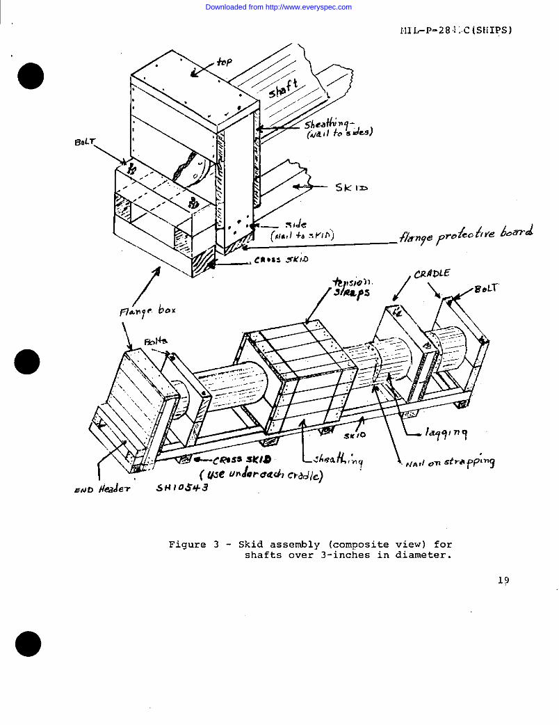
3.4 .1.2.2 Finished shafting and rough machined shaft for ings, over 3-inches indiameter. ——+ ‘—”o“e shaft complete with accessory parts, where appllcab e, shall be cradled o“ a
sk, d tYPe base (See fi9ure. 3 and 4 and YIL-c-104) for construction 9uidance. Unless other-wise specified (see 6. 2) , table 111 shall apply for skid base size members. Shafts andaccessory parts where applicable shall be so cradled, mounted, and secured o“ the skid baseto prevent shaft deflection, shifting, and damage that may result from storage, handling,.a”d shipment. Skids less than sixteen feet i“ length shall not be spliced. Larni”atirwg andsplicing of skids shall be i“ accordance with .M1L-C-104 E“d headers shall be placed flushwith the skid ends a“d bolted in place. To protect the bottom of the fla”qe, a nominal2-inch thick wood member the width of the flange box shall be secured to the skids directlybeneath the fla”ge box.
Table 111 - Sizes of members in skid assemblies forshipment of propulsion shafti”q, over 3-inchesin diameter.
Items
Skids
End headers~ro~~ ~kid,l/
craclles~/ (cutout)
~radle;l
spac, ng(maximum]Lagging
:/cradles shall be fabrthe shaft s“.gly witLaminated cradles ar<
sizes of members for shafts with diameters of
Greater than 3 8 inches toinches but less less than 16 16 to 24 inchesthan 8 i“cbes inches
Inches I Inches I Inches
4 by 4 or 2-2 by 4 by 6 [flat) 4 bY 8 (flat)4,s (flat) or 2-2 by 6,s
(flat)4by4 4 by 6 (flat] 4 by 8 (flat)
3 by 4 (flat)
2-4 by 6,s to4by8
20
4by4 4by4
2-4 by 8Ss to 2-4 by 12, s to4 by 12 4 by 16 lamin-
ate with 3/4-
36inch plywood2-1/2 timesdiameter
1bv2 t2bv2 12 by 2
Over 24 inches
Inches
6 by S (flat)
4 by 8 (flat)
4by4
2-4 by 16°3 a“dlarger laminatewith 3/4-inchply“ood2 times diameter
2by2I 1
ated i“ two equal parts, the bottom and top halves cut out to fit.11ow.”c. for preservation, wrapping, lagging or other protection.used for shafts exceeding 16 inches i“ diameter.
?/The nwber ad ~ocation of .radle, ~hould b= adjusted so that they are located at the
quarter points for sling lifting.2/ cross skids shall be located at each cradle a“d shall be bolted to the skids with the
same bolts used to fasten the cradle.9
Downloaded from http://www.everyspec.com
:llL-P-2845C [SIIIPS)
3“4”’”’%===”Propellers , 40-ponds and over shall be individually packed and
wovid.d with 1, t..g eYe bolts tO f.cilitate ProPeller handling, including Placement andremoval from its. shipping and storage container . Each ProPeller shall be marked or taggedwith the following information ,,FIANDLE BY EYE BOLTS,,. ?larki”g in fornmti.” shall be appliedL. accordance with 3.3.1.6.2.1.
3.4 .1.3.1 Thirty inches i: diameter a“d nnde=. Propellers , 30-inches in diameter andunder, shall be m.lt>ple or .nd. v.dually p=e~e 6.2) ?.s follows:
(a)
(b)
N.ltiple pack Propellers shall be packed i“ wood boxes (see figure 5).O”forrn. ng to PPP-B-621 , class 2, style 2 for type 3 load. All sheathing,ends and cleats shall be minim.m l-inch lumber . A diaaonal cleat to thesame size as the regular cleats shall be used on each =nd of the box oneintermediate set of inside cleats or battens of not less than “orni”al 1by 4-inch lumbex shall be nailed a“d clinched to the sides , top and bottommidway between tbe ends. I[ubs of propellers shall be fitted with suitablewood .0.. s with drilled centers to fit a suitable tie bolt, on which pro-pellers shall be strung. Tie bolts shall be securely s.spe”ded between theends of the box by .s.? of “Omi”al 2 by 10-inch members securely cleated tothe inside of the box ends. The size of the box shall be such as to i“stirenot less. than approximately 1 inch clearance on top, sides and ends . Boxesover 48 inches loncj shall be provided with an intermediate saddle midwaybetween tbe ends which will firmly support the tie bolt from all sidesThe saddle support shall be securely attached to the sides , top and bottomof the box. Suitable blocking which will “ot i“j.re or mar the blades shallbe provided to prevent propellers from turning on the tie bolt. Boxes shallbe provided with skids i“ accordance with the applicable box .pecificatio”.The gross “eight of each box shall not exceed approximately 600 poundsI“divid. al packs71) Propellers shall be packed in “ood boxes conforming to the requirec?e”ts
of PPP-B-621 , .1. s.s.2, style 2 (reinforced] , type 3 load as show” onfioure 6. Dlockinc! shall be cut from nominal 2 bv 6 or 2 bv 8-inchlu~ber with a mi”i& 10-inch length. Blocking s~all be cu~ i“ pairswith the angle of cut co” forrni”g to the blade angle as shown on figure7. Blocks shall be covered with at least three thicknesses of type 1,
grad. A, ,1.. s 2 mat. ri.l con fOrmin.3 to filL-B-121 at areas of contactwith the blades.
(2) When specified (see 6 .2) , propellers shall be individually packed i“corrugated fiberboard boxes conforming to PPP-B-636, class weather-xesistant , full overlap style as show” o“ figure 8. Blocki”q, braci”q ,and fillers shall be of tbe same material as the box except liners atblade contact area shall be solid fiberboard. Fillers , as required,shall be used under a“d over the hub areas and cut to fit s“.gly withinthe blocking sleeve. Propeller edges and finished faces of the hubshall be covered with barrier material .Onforminq to type 1, Vrade A,class 2 of NIL-B-121. I“earior blockin~, bracing , and fillers .s showno“ figure 8 shall be used for two and three -bladed propellers. !!ethodv .eq. ireme”ts of the appendix to the fiberboard box specifi.atio”shall apply for box closure, waterproofing, and reinforcing.
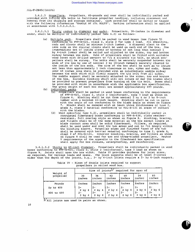
3. 4.1.3.2 T’Z E? _ diameter. Propellers shall be individually packed i“ woodboxe, .onforminq to PPP-B-621 , class 2, style 2 (reinforced) , type 3 load as show” .“figure 9. Joists shall span the box width. Table Iv provides guidance for joist sizes ,as required, for various loads and spa”. . The joist supports shall be at least 2-incheswider than the depth of the joists , e.g. , 2- by 4-inch joists require a 2- hy 6-inch support.
Table Iv - Sizes of double joists required to support
prOpellers in .ailed wOOd box.
Size of joist.~/ required for span ofWeight of
prOpeller 30 36 42 48 54 60inches inches inches inch. s inches inches
Po””ds Inches Inches Inches. Inches l“ches Inches
up to 400 2- 2- 2- 2- 2- 2-2by4 .2by 4 2by4 2by4 2by4 2by6
400 to 600 2- 2- 2- 2- 2- 2-2by4 2by4 2by4 2by6 2by6 2by6
al
~{A1l joists are used i“ pairs as shown
10
Downloaded from http://www.everyspec.com
xIL-P-2845c (SHIPS)
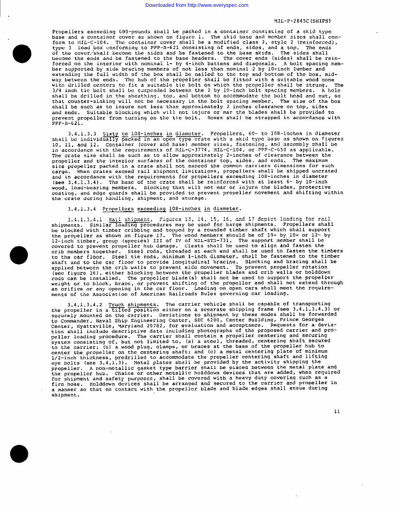
Propellers exceeding 600-pound. shall be packed in a container consisting of a skid typebase and . container cover as shown on figure 1. The skid base a“d member sizes shall con-form to MIL-C-104. The container cover shall be a modified class 2, style 2 (reinforced) ,
tYPe 3 10ad box cOnf Ormi.9 to PPP-B-621 c.nsi. ti.g Of ends, side. , and a top. The endsof the cover./sha11 become the sides and be fastened to the base skids. The sides shallbecome the ends and be fastened to the base headers. The cover ends (sides) shall be rein-forced .“ the interior with nominal 1- by 4-inch battens and diagonals. h bolt spacing mem-ber supported by side bracing members of not less than nominal 2 by 10-inch lumber andexte”di”g tbe full width of the box shall be nailed to the top and bottom of the box, mid-way between the ends.. The hub of the propeller shall be fitted with a suitable wood conewith drilled centers to fit a suitable tie bolt o“ which the propeller shall be str”nq. The3/4 inch tie bolt shall be suspended between the 2 by 10-inch bolt spacing members. A holeshall be drilled in the shcathi”g, top, and bottom to accommodate the bolt head a“d “ut, sothat co. nter-sinkina will not be .ecess.arv in the bolt Sm.cinc! member. The size of the boxshall be such as to-insure not less than ~pproximately 2’ inch& clearance on top, sides.“4 ends. suitable blocking which will “ot injure or mar the blades shall be provided to
prev.nt prOpeller frOm turning 0. t),, tie bolt. Boxes shall be strapped in accord. ”.. withPPP-B-621 .
3.4 .1.3.3 Sixt to 108-inches & diameter.shall be i“dividd ~cked in an OP.” type crate with a skid type base as shown cm figures
Propellers, 60- to 108-inches in diameter
10, 11, a“d 12. Contain. r (cover and base) member sizes, fastening, and assembly shall bei“ a.corda”ce with the requirements of xIL-c-3774 , x1L-C-104 , or PPP-c-650 as applicable.The crate size shall be such as to allow approximately 2-inches of clearance between the
prOpeller and the i.texi. r surfaces Of tl,e cOntain= *OP, sides v and ends. The naximumsize propeller packed in a crate shall “ot exceed the conuno” carr. ers d.mens. o”s for suchcargo. When crates. exceed rail shipment limitations, propellers shall be shipped uncratedand i“ accordance with the req”irenm”ts for propellers exceedi”q 108-in. hes in diameter(see 3.4.1.3.4). The base of the crate shall be reinforced with at least 6- by 10-inchwood, load-bearing members. Blocki”q that will “ot mar or i“j.re the blades, protectivecoatimg, and edge guards shall be provided to prevent propeller r,ovement a“d shifting withinthe crate d.rinq ha”dli”’q, shipment, a“d storage.
3 .4.1.3.4 Propeller. exceedi”~ 108-inches in diameter.
3. 4.1.3.4.1 ~ shipment. Figures 13, 14, 15, 16, and 17 depict loading for railshipments. similar loading procedures may be used for barge shipments. Propellers shallbe blocked with timber cribbing a“d topped by a rounded timber shaft which shall supportthe propeller ?.s show” o“ figure 17. The wood members should be of 10- by 10- or 12- by12-inch timber, group (species) 111 of IV of !41L-sTD-731. The support member shall becovered to prevent propeller hub damage. cleats shall be used to align and fasten thecrib members together. Steel rods, threaded at each end shall be used to fast.” the timbersto the car floor. steel tie rods, minimum 1-inch diameter, shall be fastened to the timbershaft a“d to tbe car floor to provide longitudinal bracing. Blocking and bracing shall beapplied between the crib walls to prevent side nmveme”t. To prevent propeller rotation(see figure 161, either blocki.q betwee. the P,OPeller blad= and crib wails Or holddOwnrods can be installed. The propeller blade (s) shall not be used to support the propellerweight or to block, brace, or prevent shifting of the propeller and shall not extend throughan orifice or any ope”i”q i“ the car floor. Loading on open cars shall meet the require-ments of the As$ociatio” of America” Railroads R“l. s governing car loading.
3 .4.1.3.4.2 Truck shipments. The carrier vehicle shall be capable of transporting
the propeller in a tilted position either on a separate sbippi”g frame (see 3.4.1.3.4. 3) orsecurely mounted o“ the carrier. Deviations to shipment by these modes shall be forwardedto commander, Naval Ship En9i”eeri”g Center, SEC 6200, Center B.ildi”g, Prince George.Center, Hyattsville, Maryland 20782, for evaluation and acceptance. Requests for a devia-
tion shall include descriptive data including photographs of the proposed carrier a“d pro-p. 1ler loading procedure. The carrier shall co”tai” a propeller centeri”q and securingsystem consisting of, but “ot limited to, (a) a steel, threaded, centering shaft securede. the carrier; (b) a wood pl”.g, clamps, or braces at the base of the propeller hub tocenter the propeller on the centering shaft; and (c) a metal centering plate of minimum1/2-inch thickness, predrilled to accommodate the propeller ce”terinq shaft and liftingeye bolts (See 3.4.1.3). Metal plates shall be provided by the activity shipping the
prOpe 1ler. A “on-metallic gasket type barrier shall be placed between the metal plate a“dtie propeller hub. Chains or other metallic holddown devices that are added, when requiredfor shipment a“d safety purposes, shall be covered with . heavy duty covering such as afire hose . Iiolddown devices shall be arranged and sec”xed to tbe carrier and propeller ina m.a””er so that no contact with, the propeller blade and blade edges shall ensue duringshipment.
11
Downloaded from http://www.everyspec.com

j,~~.p-z~~~~ (~~~ps)
15 fei;’ii”i~item ~ti~~~go~r%ilframes as shown 0. figure 18. NAVSHIPS .wg.Five or seven blade propellers, not exceeding
NY-9-BOO-B-2095021 and instructions thereon can be used for construction and propellerrnount>nq guidance .
3.4.1.3.4.4 ~ acks.+-
Each propeller shall be placed on wood skid. of sufficient @size to support the prope 1 er above the ground level. Alternatively, each propeller may besupported O. a skid type base. 1. addition, each propeller shall be provided with an open-tYPe cOver c.nsistin9 of sides, ends, and top. The cover may be of the “ailed or demo. ”table
type, a.d Of woOd or metal construction. A clearance of “ot 1.ss than two inches should beallowed between the propeller and the closest mernbex of the container cover. When in openstorage , a flexible , waterproof cover should be placed over the container. The followingspecifications. may be used for guidance for material selection, fabrication, and assemblyof the skid type base a“d cover:
Base - M1L-C-104cover - MI L-C-3774, PPP-c-650, or !41L-C-9897
3 .4.1.4 Stern tube and strut ~.—. .—
3.4 .1.4.1 Bearings or beari”q staves shall be packed i“ wood or wood-cleated plywoodboxes co” formir.q to PPP-B-621 , class 2, or PPP-B-601, overseas type , respectively , at thesupplier+. option.
3.4.1.4.2 Full molded or stave bearings not i“ excess of 90-pou.ds need not be strappedand shall be packed in wood-cleated fiberboard boxes co” forining to PPP-B-591 , class 2.
3.4.1 .4.3 Staves in excess of 1000 -po.”ds shall be packed in sheathed or coveredcrates co” forrni”g to M1L-C-104 , type 1, class 1 or 2, or PPP-c-650 . unless. otherwise speci-fied (see 6.2), selection of the crate type and style shall be at the supplier ,s option.
3.4 .1.5 Line shaft a“d thrust bearin s. Oil and qrease lubricated line shaft a“d__i’i&%all, or babbitt type shall be packed i.thrust beari”.g~ ~onii”~ r.
CO”taine.s as specified in 3.4.1.4.1.
3.4.1.6 Associated repair parts. Associated repair parts shall be packed in containersconforming to any one of the followi”q specifications at the option of the contractor.
Specification container TyPe or class
PPP-B-636 fiberboaxd Weather -res. sta”tPPP-B-640 Fiberboard, corrugated, triple wallPPP-B-585
class 2Wood -wire bo.”d
PPP-B-591class 111
Fiberboard, wood-cleatedPPP-B-621
Overseas typeWood, “ailed and lock corner O“. ?.s., ,,.1., s 2
PPP-B-650 Crates , wood , open and coveredM1L-C-104 Crate. , wood, lumber and plywood sheathedMI L-C-3774 Crate, , wood open
Shipping containers , except PPP-B-636 fibexboard boxes , shall be closed a“d reinforced inaccordance with the applicable container specification or appenrlix thereto. PPP-B-636fiberboard boxes shall be closed , waterproofed, and reinforced in accord. ”.. with method V,
appendix to PPP-B-636. The gross weight of wood, cm wood-cleated boxes shall “Ot exceed# 200-po. nds , except when a single item exceeds 200-po.nds Fiberboard boxes shall not exceed
the weight lirnitatio”s of the applicable fiberboard box specification. Shippi”q co”t?.in’ar.,except crates a“d PPP-B-636 fiberboard boxes, shall have case liners co” formi”q to XIL-L-1054>. C.ascliner. shall be closed in accordance with MIL-L-10547. Barrier material con-forming to MIL-B-13239 may be used to fabricate the caseliner. When boxes are packed withitems or interior packages meeti”q the following requirement. , c.seli.. rs arc not required(see 6.2):
(a)(b)
(c)(d)
Items. which are completely painted and have no unprotected critical surfaces.Large items which are completely coated with preservative type P-1 or P-19 ,with critical interior item surfaces preserved a“d all openings scaled .ithauthorized material.
Method lC or 1A packagesInterior packages which conform to Weatl,er-resistant type!+ or class a“d arewaterproofed i“ accordance with the applicable interior package containerspecif ic.atio”.
12
Downloaded from http://www.everyspec.com
MIL-P-2845c (SHIPS]
3.4 .1.6.1 _ arts bOxes.+—
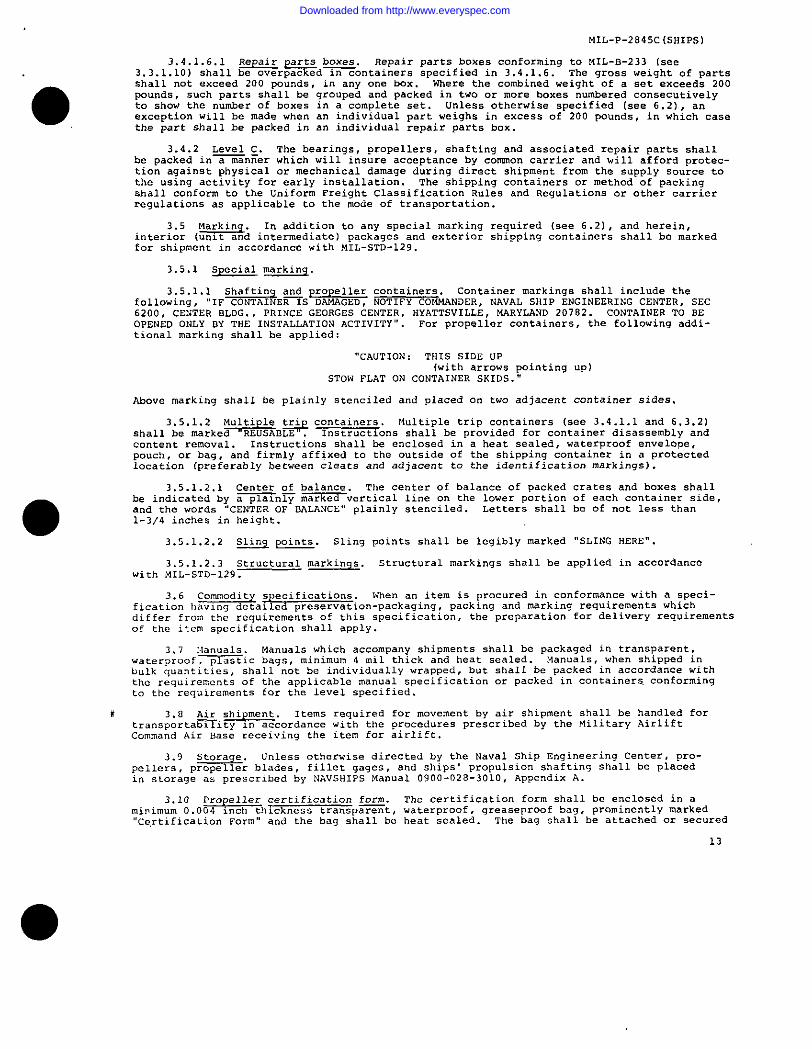
Repair parts boxes .Onforminy to NIL-B-233 [see3.3.1.10) shall be overpac ed in containers specified in 3.4.1.6. The gross weight of parts
●,
shall not exceed 200 pounds, in any o“. box. where the comhi”ed weight of a set exceeds 200
pOunds, such Parts shal 1 be 9ro.ped and Packed in two or more boxes numbered consecutive yto show the number of boxes in a complete set. unless otherwise specified (see 6.2) , anexception will be made when an individual part weighs i“ excess of 200 pounds, in which casethe part shall be packed i“ an individual repair parts box.
3.4.2 ~ ~. The bearings, propellers, shafting and associated repair parts shallbe packed in a manner which will i“s.re acceptance by .onunon carrier a“d will afford protec-tion against physical or mechanical damage d;ri”g direct shipment from the supply so.~ce tothe “si”g activity for early installation. The shipping containers or method of packingshall conform to the Uniform Freight Classification Rules a“d Regulations or other carrierregulations as applicable to the mode of transportation.
3.5 MF!. In addition to any special marki”q required (see 6 .2) ,interior (.nlt a“d intermediate] packa~es and exterior shipping containersfor shipnent in accordance with MIL-STD-129.
3.5.1 Special markin~.
and herein,shall be marked
3.5.1.1 Shaft in% a“d propeller containers. Container markings shall include thefollowing, ,,If CO NTAINER~S DAMAGED , NOTIFY COMMANDER, NAVAL SHIP ENGINEERING CENTER, SEC6200, CENTER BLDG. , PRINCE GEORGi?S CENTER, HYATTSVILLE , MARYLAND 20782. CONTAINER TO BEOPENED ONLY BY THE lNsTALLAT10t4 ACTIVITY,, . For propeller contaimars, the following addi-tional “arking shall be applied:
“CAUT108 , THIS SIDE UP(with arrows pointing up]
STOW FLAT ON CONTAINER SKIDS. “
Above marking shall be plainly stenciled and placed o. two adjacent container sides.
3. 5.1.2 l.!”~tiple trip containers . M“ltiple trip co”tai”ers (see 3.4.1.1 and 6.3.2)shall be marked REUSABLE,, . l“struct Cons shall be provided for container disassembly andcontent removal. Instr”ctio”s shall be enclosed in a heat sealed, waterproof envelope,
POUCh, Or b.w, a.d firmlY affixed to the outside of the shipping container in a protectedlocation (preferably between cleats and adjacent to the identification markings) .
3.5.1 .2.1 center of balance. The center of balance of packed crates a“d boxes shall——be indicated by ~nly marked vertical line on the lower portion of each container side,a“d the words ,“CENTER OF BALANCE<, plainly stenciled. Letters shall he of not less than1-3/4 i“.hes in height.
3.5.1 .2.2 Slirq points. Sliiq points shall be legibly marked ,,SLING HERE”.
3 .5.1.2.3 Str”ct”ral ntarki”qs. Structural markinqs shall be applied in accordancewith ,YIL-STD-129 .
3.6 Commodity specifications . when .“ item is ~roc.red i“ conformance with a speci -
fic.tio. 1~..i.g deta,led prese~vation-packa9 i.g, packing a.d markin9 requirements whichdiffer from the requirements of this specification, the preparation for delivery requirementsof the item specification shall apply.
1.7 Manuals. Ma””als which accompany shipments shall be packaged in transparent,waterproof, plastic bags, rni”im.m 4 nil thick a“d heat sealed. Manual. , when shipped i“bulk quantities, shall not be individually wrapped, but shall be packed in accordance withthe requirements of the applicable nmn”al specification or packed i“ containers. conformingto the requirements for the level specified.
# 3.8 Air shipment. Items required for movement by air shipment shall be handled fortransportab~ity L“ accordance with the procedures prescribed by the Military AirliftCmmna”d Air Base receivirrq the item for airlift.
3.9 ~. unless otherwise directed by the Naval Ship Engi”eerinq Center, pro-pellers, propeller blades, fillet gages, and ships, proeul. iO. shaftiw ,h.11 be pla.edin storage as prescribed by NAVSHIPS Manual 0900-028-3010, Appendix A.
3.10 Propeller certification ~. The certification form shall be enclosed in aminimum 0.004 inch thickness transparent, waterproof , greaseproof bag, prominently marked,rce,rtification Form,, and the bag shall be heat sealed. The baq shall be attached ox sec”zed
13
Downloaded from http://www.everyspec.com

MIL-p-2845c(sHIPs)
to the propeller hub or blade in a manner so that it is visible , readily available , and willremain with the propeller until propeller usc . When ProPellers ,,, boxed or crated , thebag may be firmly affixed to the outside of the shipping container in a protected location,
Preferably between the cleat. on the end of the co”tai”er adjacent to the identificationmark, iys—
3.11 workmanship. workmanship shall be such that , whc” the Pro Per Procedure. arefollowed, materials and equipment being processed, cleaned , preserved-packaged, packed andmarked, will receive protection against corrosion and deterioration during shipment and
Prolonged periods of storage, a“d will require minimum of reprocessing for service orfurther storage.
4. QUALITY ASSURANCE PROVISIONS
4.1 Responsibilit~ ~ i“spectio”. unless otherwise specified in the contract orpurchase order, the Suppler 1. responsible for the performance of all inspection req. ire-me”ts as specified herein. Except as otherwise specified in the contract or order , thesupplier may use his OW” or a“y other facilities suitable for the performance of the inspec-tion req”iremer. ts specified herein, unless disapproved by the Gover”me”t. The Governmentreserves the right to perform any of the inspections set forth i“ the specification wheresuch inspections are deemed necessary to ass+ure supplies and services conform to prescribedreqnireme”ts.
4.2 lnspectio” . The?X shall be two types of inspection i“ accordance with MIL-P-116 ,as follows :
(al First article (see 4.2.1) .(b) Quality conformance (see 4.2 .2] .
4 .2.1 First article .
4 .2.1.1 First article inspection Q. The contractor shall co”d.ct inspection on0“. complete package, packed for shlpnu?nt , to ascertain that the cleaning , drying, preser -vat.on-packaging, packing, and marki”q of the eq. ipme”t or item co” forms to this specifi-cation. The first article sample will “ot be required when such a pack bas previously beeninspected and accepted for the same method for an identical or similar item by the samecontractor and satisfactory evidence ca” be f“r”ished to the Government that the equipmentor items have been prepared identically with the previously .ippproved pack. First articleinspection shall be repeated when changes i“ pres. rvatio”-packagi”q a“d packing materials ,or processes or designs are made
4 .2.1.2 First article examinations and tests . The sample first article pack of theequipment or i~all be s.b]ected to t=t?=atio”s and tests of !IIL-P-116 a“d thetests .s specified hereinafter. A first article test will “ot be required when o“e of thefollowing applies :
(a) Level C packaging is specified.(b) Level C packing is specified.(c) Detalled packx”g i“structiorm are f“r”ished by the procuring activity.
4.2.1.2.1 ROugh-handlin~ =. h’he” specified (see 6.2) , rough-handling tests shallbe .C.nd”cted . Tests shall be as specified in :41L-P-116 . for packs exceeding 200 pounds(or 100 pounds where eq”ip!nent is secured to the base of the co”tai”er) the railroad cartest method of 4 .2.1.2.1.1 may be “s.d in place of the pendulum-in!pact test or incline -impact test of MI L-P-116 at the option of the contractor.
4 .2.1.2.1.1 Railroad car test method. The pack shall be securely blocked to PreventlllCW.lU.”t0“ the car . A“tl-=d plates shall not be used for this test. The car shall beimpacted at approximately 10 miles per hour.
4 .2.2 Quality conformance inspection.
4.2.2.1 samplin~. sample items, packages and packs shall be selected and inspectedto determine con forrna”ce to the req”irem.e”ts of section 3 herein i“ accordance withMXL-P-116 .
4 .2.2.2 Examination.
4 .2.2.2.1 Preservation-packa.gin=. ExanIi”ation of the preservation-pa.ckagi”.g, a“dmarking .eq”ireme”ts not covered by referenced specifications shall be per forraed o“ the basisof the smnpli”g procedures and i“spe. tion levels bei”q used ‘co determine exarnin.atio” require-ments under !41L-P-116.
14
Downloaded from http://www.everyspec.com
MI L- P-2845C (sH1ps)
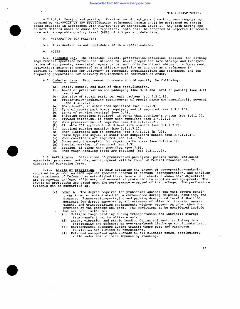
..vAi2iz”M-P%&% %$*&tion referenced herein shall be performed m sampleExamination of packing and marking requirements not
e
packs selected in accordance with MIL-STU-l Q5 at inspection level 1. Any pack having qneor more defects shall be cause for rejection. Lots shall be accepted or rejected in accord-ance with acceptable quality level (AQL) of 2.5 percent defective.
5. pREpARAT1ON FOR DELIVERY
5.1 This section is rmt applicable to this specification.
6. NOTES
6.1 Intended use . The clea”i”g , drying, preservation-packaging, packing, and marking—.requirements specxfled herein are intended to insure proper and safe storage and tra”spor -tatio” of equipments, associated repair parts, a“d tools for direct shipment to Governmentactivities; shipments processed at a military activity or agency; as a reference i“section 5, ,,Preparation for Delivery,, of commodity specifications and standards, and for
preearin9 preparation. for delivery requirements in contracts Or order.
6.2 OrderinT data . Procurement documents sbo.ld specify tbe following:
(a)(b)
(c)(d)
(e)(f)(g)[h)(i)
(j)(k](1)(ml(n)(0)(p)
Title, “umber, and date of this spe. if ication.Level of cmeservation and Dackaai”~ (see 3 .3) and level of Dackina (see 3.4). . . . .required:
Quantity of repair parts per unit package (see 3.3. 1.8) .Preservat xo”-packaqi”g req.ireme”ts of repair parts not speci fical ly covered(see 3.3.1.8.1).
Box closure, if other than specified (see 3.3.1.9) .
TYPe of reP.i I Part boxes reqnired, and if required (see 3 .3.1 .10) .Level of packing required (see 3.4) .Shipping container required, if other than supplier, s option (see 3.4 .1.1) .Plywood selection, if other than specified (see 3.4 .1.1 .2) .Wood preservative, if required (see 3.4.1.1.3.1.2) .If table 111 applies to skid base size members (see 3.4.1.2.2) .Required packinq quantity (see 3.4.1.3 .1) .When fiberboard box is remixed [see 3 .4.1.3.1 [b) (2) ).Crate type and style, if other than supplier ,s option (see 3.4.1.4. 3) .when caseliners are required (see 3.4.1. 6) .Gross weiqht exception for repair parts boxes (see 3.4 .1.6 .1) .
●(q)(r)(s1
6.3 Definitions. De fi”itio”s of preservation-packaqinq, packing terms, includinqmaterials, processes, methods, and equipment will be found in Federal Standard No. 75,
sp=ial marki.g, if requir+ @e 3 .5).Storaqe, if other than spec. f.ed (see 3.9)when ro”qh ha”dli”g tests are required (see 4. 2.1.2.1)
Glossary of Packaqinq Terms.
6 .3.1 Levels of protection. To help determine tbe extent of preservation-packaq inqrequired to protect a“ item agafnst specific hazards of storaqe, transportation, and handling,the Department of Defense has established three levels of protection whose main objectivesare to provide uniform, efficient, and economical protection to supplies and equipment. Thelevels of protectib” are based upon the performance expected of the packaqe. The performancecriteria can be summarized as :
(a) Level A. The degree required for protection against the most severe condi -~known or anticipated to be encountered d.rinq shipment, handling, andstoraqe. Preserv.stio”-packaging and packinq designated level A shall bedesigned for direct exposure to all extremes of climatic, terrain, opera-tional, a“d txansportatio” environments without protection other than that
prOvided bY the packaqe and pack. The .onditio”s to be considered includeb“t are “ot limited to:(1) Multiple rough h.”dling during transportation and intransit storage
from nm”.facturer to ultimate user.(2) shock, vibration and static loading durinq shipment, including deck
shiploading and offshore or over -the -bea.b discharge to ultimate user.(3) Environmental exposure during transit where port and warehouse
facilities are limited or nonexistent.(4) Extt?”ded unimproved open storage in .11 climatic zones, particularly
while under static loads imposed by stackinq.
15
Downloaded from http://www.everyspec.com

MIL-P-2845c (SHIPS)
(5) Special package and pack features for field and combat operations(handling and utility] .
(6) special features are required by combat development agencies.(b) Level C. The degree required for protection under know” favorable conditions
~ shipment, ha”dli”g and limited te””re of storage. Preservation-
Pac~a9i.9 an? packing designated level c shall be designed to prote& itemsagaxnst physical and envxronrnental damage during know” favorable conditionsof shipment, handling and storage. In general , the followiny criteria willdetermine the requirements of level c.(1) Limited handling during transportation and intransit storage.(2) Limited shock, vibration and static loadinq during the tra”sportatio”
cycle .(3) Controlled warehouse e“viromnent for temporary periods.[4) Effects of environmental exposure during shipment a“d intra”sit delays.(5) Stacking and Supporting superimposed loads during shipment and temp,JrU-y
storage.(6) Item characteristics require no special or peculiar preservation-pack-
agi”q and/or packi”q provisions .
6 .3.2 Multiple trip container. The design features axe such that, subject to simplereplacement of components, the .Ontai”er can be employed for more than one ro””d trip frominitial supply source to the consumer and ret”r”. A typical example is a remountablewooden box/crate equipped with fasteners permitting ready assembly, disassembly, a“dreassembly.
6.4 Detailed information. S“ppleme”tal i“for!nation on preservation-p.ackaqinq, a“d
packing IOaY be found in the following manual.:
DSAM4145.2 V.’J1.I, TM38-230-1, NAVAIR 15-01-1, AFP 71-4, Vol. 1, MCO P4030.3Preservation, Packaqi”q and Packing of Military Supplies and EquipmentPreservation a“d Packaqi”q (volume 1) (Federal Stock Number 0715-010-0290)
DSAM4145.2 Vol. 11, TM38-230-2, NAVAIR 15-01-2, kFP 71-4, MCO P4030 .21APreservation, Packaging and Packi”q of Military Supplies a“d Eq.ipme”tPacking (volume 11) (Federal Stock Number 0715-010-0280 )
DSAM4145 .7, TM38-236, NAVAIR 15-01-3, AFP 71-8, MCO P4030 .30Preparation of Freiqht for Aix Shipment (Federal Stock Number 0715-010-270)
DSAM4145 .3, TM38-236, NAVAIR 15-01-3, AFP 71-8, MCO P4030.30Packaging a“d Handling of Dangerous Materials for Tra”sportatio” byMilitary Aircraft (Federal Stock Number 0715-010-0021]
(Copies of these ma””?.ls may be obtained “pen application to the Coma”ding Officer,Naval Publications and Forms Center , (NPFC 105) 5801 Tabor Ave.”., Philadelphia, Pe”rIsyl -va”ia 19120. )
6.5. First article inspection..—
6.5.1 Invitations for bids should provide that the Government reserves the right towaive the req”ixement for samples for first article i“spectio” as to those bidders of ferinq
a Pr.~u@ which ha. bee. PreVlOuSIY procured or tested by the Government, and that biddersof ferlnq such products , who w.sb to rely on such prod”ctio” or test , nl”st furnish evidencewith the bid that prior Government approval is pxesently appropriate for the pending pro. ”re-rne”t.
6.6 THE .MARGINS OF THIS SPEC1F1CATION ARE MARKED ‘“#+,TO INDICATE WHERE CHANGES (ADD1-TIONS , MOD IF1CATIONS, CORRECTIONS , nELETIONs) FROM THE PREVIOUS 1s5uE nAvE BEEN MADE. THISWAS DONE AS A CONVENIENCE ONLY AND THE GOVERNMENT ASSUMES NO LIABILITY WHATSOEVER FOR ANYINACCURACIES IN TIIESE NOTATIONS. BIDDERS AND CONTRACTORS ARE CAUTIONED TO EVALUATE THEREQU rREMENTS OF THIS DOCUMENT BASED ON THE ENTIRE cONTENT IRRE5pECT1VE OF THE MARGINALNOTxrlO. w MD RELAT10N2J11p TO THE LAST PREVIOUS ISSUE.
Preparirq acti”ity:Navy - SH[Project PACK-0492)
16
Downloaded from http://www.everyspec.com

MIL-P-2845c (SIiIPSj
~cs-tible \w,4h liailS,
COVER
1;
de.
BA5E
Figure 1 - Cover and base (modified nailed-wood box) for
propellers up to 60 inches in diameter.
17
Downloaded from http://www.everyspec.com

MIL-P-2845C(SHIPS)
far
s)
Al+c-na+e qraindirection
I/d” p~y.vood7
T~~”. cj~”
or 7.L”
gjk~10 1-
Ly CRADLE
Figure 2 - Wood box for shafting under three inches in diameter.
18
Downloaded from http://www.everyspec.com
1.lIL-P=-28J..C(S!iIPS)
E,.JLI Healer SUIO.S*3
&7rd
Figure 3 - Skid assembly (composite view) forshafts over 3-inches in diameter.
1?
Downloaded from http://www.everyspec.com

i31L-P-2345C (SHIPS)
.LAkf\ NATION+_
sng9v2 Figure 4 - Skid assembly details.
26
Downloaded from http://www.everyspec.com

I
8 z YELLOW PJNE~?..o” S1OC.K
Figure 5 - Box for
sti%943
boat propellers 30 inches and under.
Downloaded from http://www.everyspec.com

MIL-P-2845C (SHIPS)
22
END
~heath; nq
v s+.dppinq
ToP VIEW(. 4- blade prope\\cr)
ToP V(EW
(3- blcda prO~cl\er”)
SHI054+UANDLING 5KID5
Figure 6 - Nailed wood box for propellers30 inches in diameter and under.
(ZXA)
Downloaded from http://www.everyspec.com

Figure 7 - Blocking for propellers 30 inches in diameter and under.23
Downloaded from http://www.everyspec.com

MIL-P-2845c(S11<PS)
hub ~ I /’\ /““’-J’”
5,:::+ 4
prote
Fillb?
ugated f(be.bloc k
Figure 8 - Fiberboard pack for propellers 30 inches in diameter and under.
J‘:
Downloaded from http://www.everyspec.com

llIL-P-2!845C(SIIIPS)
-Ciecd/
Figure 9 - Wood box for propellers 30 - 60 inchesin diameter, not exceeding 600 Dounds.
25
Downloaded from http://www.everyspec.com

MIL-P-2845C (S1iIPS)
END
END
d’i’”5*$
ail
51DE
Figure 10 - Open type crate covers for propellers60 to 108 inches in diameter.
Downloaded from http://www.everyspec.com

Loadbear;mem bem
Platlorm,wood or plyuxcd
*
id
End
COVERED TYPE SKID
EioltHeader-D,Xjm(ll
p
-+ 1+’kk,!,,> J l$W:l-
A --- —–+j frivw mcfmhe, c} s“de,. ,., . ._ ,_-.....-— . .
1
::
, ~ >Lo.,&<,i.l,L(l ,,WI.AX.
G ‘;!~_J-j<._...l...l .....__. ....L..l~
j i ~“:i.1 -!b’_.._..-..-I:fIC.I.....-.1~J-
-—._—— --.:..,- ..
‘ w-c. fi,,kn,y, J ,,(1(I,Mlld
OPENlYPE SKID
Figure 11 - Skid type bases for propellers60 to 108 inches in diameter.
:27
Downloaded from http://www.everyspec.com

L-NJ V:ed
v v v
/
CiB
28
sLfe V;.ew
Figure 12 - Propeller anchoring.
Downloaded from http://www.everyspec.com

ilIL-P-2845C (S1:IPS)
.:,-
si-j
Figure 13 - Loading of propellers (more than108 inches in diameter).
f’qqq29
Downloaded from http://www.everyspec.com

~.\IL-P-,2845C(Slil.PS)
Figure 14 - Loadillg of propellers (more than108 inches in diameter).
SH gq4x
30
Downloaded from http://www.everyspec.com

:IIL-P-2845C (S I!IPS)
●
Figure 15 - Vertical shipment of propellers(more than 108”inches in diameter).
31
Downloaded from http://www.everyspec.com

MIL-P-2845C(SH1PS)
+
6)
@
32
Downloaded from http://www.everyspec.com

e>”lt
?,e rod ,
DROPPED-CENTER CAR
END View 5 I D.E VIEW
TOP VIEW
Figure 17 - Blocking of large propeller.
Downloaded from http://www.everyspec.com

I;IL-P-2845C(SH1PS)
34
Downloaded from http://www.everyspec.com

MIL-P-2845C [SHIPS)
INDEX
Accessories . . . . . . . . . . . . . .. . . . . . . . . . . . .Air shipment . . . . . . . . . . . . . . . . . . . . . . . . .Anchoring, blocking, bracing and cushioning . . . . . . . . . .
Applicable dO. ~ents. . . . . . . . . . . . . . . . . . . . .As.so.iated repair parts. . . . . . . . . . . . . . . . . . . .
Barrier materials.. . . . . . . . . . . . . . . . . . . . . .Bearings . . . . . . . . . . . . . . . . . . . . . . . . . . .
Center of balance.. . . . . . . . . . . . . . . . . . . . . .Changes from previous issue . . . . . . . . . . . . . . . . . .Closure of openings . . . . . . . . . . . . . . . . . . . . . .commodity specifications . . . . . . . . . . . . . . . . . .Cushioning materials . . . . . . . . . . . . . . . . . . . . .
De finiti.a”s . . . . . . . . . . . . . . . . . . . . . . . . . .Detaile.d information.. . . . . . . . . . . . . . . .... .Disassembly . . . . . . . . . . . . . . . . . . . . . . . . . .Disassembly and matchmaking . . . . . . . . . . . . . . . . .
Examination . . . . . . . . . . . . . . . . . . . . . . . . . .Exter”al metal s”rfaces . . . . . . . . . . . . . . . . . . . .
Figures :Figure 1 - Cover a“d base (modified nailed wood box) for
propellers UP to 60 inches in diameter . . . .
Figure 2 - wood box for shafting under three inchesin diameter.. . . . . . . . . . . . . .
figure 3 - Skid assembly ic~mposite view) for shaftsover three inches in diameter . . . . . . . .
Figure 4 - Skid assembly details . . . . . . . . . . . . .figure 5 - BOX for boat propellers 30 inches and under . .Fiqure 6 - Nailed wood box for propellers 30
diameter and under ~ . . . . . .Figure 7 - Blocking for propellers 30 inches
Paragraph“umber
3.3.1.23.83.4.1 .1.123 .4.1.6
3.3.1.133.3.1.7
3.5 .1.2.16.63.3.1.4
:::.l .12
6.36.43.3.1 .1.13.3.1.1
4.2.2.23.3.1 .3.2
3.4.1 .1.3.1.1and 3.4.1.3.2
3.4 .1.2.1
3.4.1 .2.23.4.1 .2.23.4.1.3.1 (a)
inches in. . . . . . 3.4.1.3.1(h)
in diameter. . . . . . 3.4.1.3.1(b)(1)
~nches in. . . . . . . 3.4.1 .3.1(b)(2)
and under . . . . . . .Fig!”re 8 - Fiberboard p~c~ ;o~ propellers 30
di.armter a“d under . . . . . .Fiqure 9 - Wood box for propellers 30 - 60 ~nches in
diameter, not exceeding 600 pounds ~. . . . . .Fiqure 10 - Open type crate covers for propellers 60 to
108 inches i“ diameterFigure 11 - Skid type bases for propeil~r~ ;O “t; iO~ ‘ “ “
znches in diameter. . . . . . . . . . . . .Figure 12 - Propeller anchori”q . . . . . . . . . . . . .
* Figure 13 - Loading of propellers (more than 108 inchesi“diameterl . . . . . . . . . . . . . . . .
# Fiqure 14 - Loading of propellers (more than 108 inchesi“ diameter) . . . . . . . . . . . .
* Fiq”re 15 - Vertical shipme~t”ok ~ropellers (more than 108
3.4 .1.3.2
3.4.1 .3.3
3.4 .1.3.33.4 .1.3.3
3.4.1 .3.4.1
3 .4.1.3.4.1
F+n+shed machined su;faces . ~- . ; . . . . . . . . . . . . . .Fz”lshed shafting and rough machined shaft forgings, overthree inches i”di.ameter . . . . . . . . . . . . . . . . . . .
First article . . . . . . . . . . . . . . . . . . . . . . . .First article examinations and tests . . . . . . . . . . . . .First article inspectio” . . . . . . . . . . . . . . . . . . .First article inspection sample . . . . . . . . . . . . . . . .First article sample.. . . . . . . . . . . . . . . . . . . .
inches indianeter). . . . . . . . . . . . . 3.4 .1.3.4.1Fi.gure16 -Well car . . . . . . . . . . . . . . . . . . . 3.4 .1.3.4.1Figure 17 - Blocking of large propeller . . . . . . . . . 3.4 .1.3.4.1Fiaure 18 - Prc.Deller shi DDinu frame . . . . . . . . . . . 3.4 .1.3.4.3
3 .3.1.3.4
3.4.1 .2.24.2.14.2.1.26.54 .2.1.13.1
Page
5138
1;
76
13165
137
1516
:
145
17
18
192021
22
23
24
25
26
2728
29
30
;;33345
1:1416143
35
Downloaded from http://www.everyspec.com

MI L-P-2845C (SHIPS)
INDEX [continued )
Gener,a,l ,requirements , level A packing . . . . .. . . . . . . . .
Index listing of repair parts and tools . . . . . . . . . . . .Inspection . . . . . . . . . . . . . . . . . . . . . . . . . .Intended ise . . . . . . . . . . . . . . . . . . . . . . . . .I.ternal metal s.rfaces . . . . . . . . . . . . . . . . . . . .
Level A packing .,. . . . . . . . . . . . . . . . . . . . . ..Level A preservation-packaging . . . . . . . . . . . . . . . .Level c lacking . . . . . . . . . . . . . . . . . . . . . . . .Level C ,preservation-p ackaging . . . . . . . . . . . . . . .Levels of protection.. . . . . . . . . . . . . . . . . . . .Line shaft and thrust bearings . . . . . . . ,. . . . . . . . .
Main propulsion shafting . . . .. . . .. . . . . . . . . . . . .Three inches in diameter and less . . . . . . . . . . . .
Manuals . . . . . . . . . . . . . . . . . . . . . . . . . . . .Marking’ . . . . . . . . . . . . . . . . . . . . . . . . . . . .Matchmaking . . . . . . . . . . . . . . . . . . . . . . . . .Material s....... . . . . . . . . . .. . . . . . . . . . .Multiple trip containers. . . . . . . . . . . . . . . . . . .
New material s...... . . . . . . . . . . . . .Note, . . . . . . . . . . . . . . . . . . . . . . .
Order ing data.... . . . . . . . .. . . . . . . .Other publications . . . . . . . . . . . . . . . .Other repair parts... . . . . . . . . . . . . .
Packing . . . . . . . . . . . . . . . . . . . . . .Packinq.ndmarklng. . . . . . . . . . . . . . . .Plywood . . . . . . . . . . . . . . . . . . . . . .Preparation for delivery . . . . . . . . . . . . .Preservation-packaqinq . . . . . . . . . . . . . .Preservation-packaging and markinq . . . . . . . .Preservative aDD1ication . . . . . . . . . . . . .Preservative tyeatner.t . . . . . . . . . . . . . .Propeller certification form . . . . . . . . . . .Propel leas . . . . . . . . . . . . . . . . . . . .
propellers thirty inches in diameter and underpropellers thirty to sixty inches in d$ameterPropellers sixty to 108 inches in diameter . .Propeller. exceeding 108 inches in dia.rneter .
Propeller shippirg frame . . . . . . . . . . . . .
Qu2.l+tY assurance provisions . . . . . . . . . . .Quallty conformance inspection . . . . . . . . . .
. . . . . .
. . . . . .
. . . . . .
. . . . . .
. . . . . .
. . . . . .
. . . . . .
. . . . . .
. . . . . .
. . . . . .
. . . . . .
. . . . . .
. . . . . .
. . . . . .
. . . . . .
. . . . . .
. . . . . .
. . . . . .
. . . . . .
. . . . . .
. . . . . .
. . . . . .
Railroad carte strnethod . . . . . . . . . . . . . . . . . . .Rail shipment . . . . . . . . . . . . . . . . . . . . . . . . .Repair parts boxes... . . . . . . . . . . . . . . . . . . .
Repair pa.t.5andt001s . . . . . . . . . . . . . . . . . . . .Responsibility for inspection . . . . . . . . . . . . . . . . .Req”iren!e”ts . . . . . . . . . . . . . . . . . . .. . . . . .Rouqhhandli”g tests.. . . . . . . . . . . . . . . . . . . .
sampling . . . . . . . . . . . . . . . . . . . . . . . . . . .Scope . . . . . . . . . . . . . . . . . . . . . . . . . . . . .Shafting . . . . . . . . . . . . . . . . . . . . . . . . . . .Shafting and propeller co”t?.iners . . . . . . . . . . . . . . .shafting three inches i“ diameter, etc. . . . . . . . . . .
Paragraphnumber Page
3.4 .1.1 7
3.3.1.11 74.2 146.1 153.3.1 .3.3 5
3.4.1 73.3.13.4.2 1;3.3.26.3.1 1;3.4.1.5 12
3.4 .1.2 83.4.1 .2.13.7 1:3.5 133.3.1 .1.2 43.2 33.4.1.1.2.1,3.4.1.1.3.1.1, 8, 13,3.5.1.2, 6.3.2 and 16
3.2.16
6.22.23.3.1 .8.1
3.44.2.2 .2.23.4 .1.1.253.34 .2.2.2.13.3 .1.33.4.1 .1.3.1.23.103.3.1.6 and3.4.1.3
3.4 .1.3.13.4.1 .3.23.4.1 .3.33.4.1 .3.43.4 .1.3.4.3
44 .2.2
4 .2.1.2.1.13.4.1 .3.4.13.3.1.10 a“d3 .4.1.6.1
3.3.1.84.134 .2.1.2.1
4.2.2.113.3.1.53.5.1.13.4 .1.1.3
315
1526
7158
15
1:5
1:6 and101010111112
1414
1411
7 a“d 13
1:
1:
141
1;8
36
Downloaded from http://www.everyspec.com
MIL-P-2845C (SHIPS)
INDEX {continued).
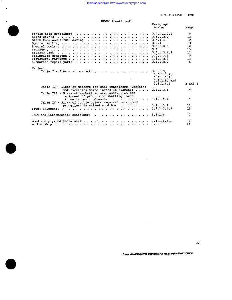
Single trip containers . . . . . .Sling paints . . . . . . . . . . .Stern tube and strut bear+ng . . .Special marking . . . . . . . . . .Special tools . . . . . . . . . . .storage . . . . . . . . . . . . . .Storage pack . . . . . . . . . . .Strippable compound . . . . . . . .stru. t”ral markinqs . . . . . . . .
Submarine repazr parts . . . . . .
Tables :Table 1 - Preservation-packing . . . . . . . . . . . . . .
Table 11 - Sizes of members for wood containers , shaftingnot exceeding three inches in diameter . . . .
Table 111 - sizes of members i“ skid assemblies forshipment of propulsion shaf.ti”.g, overthree inches in diameter . . . . . . . . . .
Table Iv - Sizes of double joists required to supportpropellers in nailed wood box . . . . . . . .
Tr”ckshipne”ts . . . . . . . . . . . . . . . . . . . . . . . .
Unit and intermediate containers . . . . . . . . . . . . . . .
Wood and plywood containers . . . . .. . . . . . . . . . . . . .workmanship . . . . . . . . . . . . . . . . . . . . . . . . . .
Paragraphnumber
3 .4.1.1.2.23.5.1 .2.23.4 .1.43.5.13.3.1 .8.33.93.4 .1.3.4.43.3.1 .3.13.5.1 .2.33.3.1 .8.2
3.3.1.3,3.3.1.3.2,3.3.1.3.4,3.3.1.8, and3.3.1 .8.1
3.4 .1.2.1
3.4.1,2.2
3.4.1,3.23.4.1,3 .4.2
3.3.1.9
3.4.1 .1.3.13.11
12
1:6
3 a“d 4
9
9
1011
7
814
37
*UX wvuNMwr QUNnNG omcr? nn - 404anmm
Downloaded from http://www.everyspec.com

,
INSTRUCTI ~S: [n ● continuing effort to mke our staadardkzation documentsbetter,the fkID provides this form for w in
mbmitting commenb and suggestion for imkwovements. Ml usem of military stnndmfiz.ation docwmezib am invited to provide. suggestions. TbkL form may b detached. folded along tbe Iinu imfi@ed, taped along the loose edge (00 NOT STAPLE), nnd
c
mailed. In blark 5, be M merifm u paccitde about particularproblem m such u wording which required interpretation, .M
too rigid, restrictive, 100% uubiguous, or wu imcompatibte, and gire pmpmed wording cbanga which would atteviak the
probtenn. Entn in blork 6 any mnarlu not related to a specifii parag?apb of the document. If block 7 is fried out, an
acknowledgement witl be msiled to You within SO days to let You know that your commen~ wem received and are beinguvuidered.
.NOTE: TM form IMY not be used LO request copies Of documenti, nor to reque#t waiverc, deviations, or clarification of
specification requirements on current contracts. Comments submitted on thii form do not constitute or imply authorization
to wsiw my portion of the referenced document(#J or to amend contractual requireunnti.
(Fold dmu thb 11=)
(Fold alon, tht! he)
0EPAR7MEN7 OF THE NAVY
111111OFFICIAL SUSINE=PENALTV FOR PRIVATE uSE $300 BUSINE:SNoR~PIJ’MAil$,
FIRST CLASS
POSTAGEWILL BE PAID BY THE DEPARTMENTOF THE NAVY’
LNOPOSTAGENECES+RVIf MAILEO
IN THE
UNt’TEO STATES
Connmnder, Naval Ship Engineering Center
Code 6124, Center Tmilding
Prince George’s Center
Hyattsville, MII 20782
Downloaded from http://www.everyspec.com

II
I
IIIII
IIII
I
I
I
STANDARDIZATION DOCUMENT IMPROVEMENT PROPOSAL “’(Seelnstructto?m- Rfverie Side)
DOCUMENT WUMaEi4 2. 00 CUMEN7 TITLE
NAME OF SUBMITTING ORGANIZATION 4, TYPe OF ORGANIZATION (Muh .“,)
❑ VENDOR
❑ USER
K10RE5S[Shwet, City, 8w8. ZIP c-%&)
❑ 14AN”,AC7”.ER
~ O,”rln,.spw,fy,
PROBLEM AREAS
a P.roomPII Numbm and WWdi”Il:
& RaC0”17N.ti W ordl.o:
. . R.OOn/R.ii. n.l. for n.canm-o.d.! i..:
REMARKS
L NAME OF SU8M8TTER .w, Fiist MU - OP,IO.4 b. WORK TE Lf PHONE NuMBER (l”cIu& A=.Co&) -00,10”,1
MAILING ADD flESS (Slmel. City. Statr. ZIP Co&) - 0P,Io”4 0. DATE OF SUBMISSION (YYMMDD)
PREVIOUS EOITION IS IWSOLETE
Downloaded from http://www.everyspec.com