padova use, care, and installation guide guide d
TRANSCRIPT
Use
, Car
e, a
nd
Inst
alla
tio
n G
uid
e
Model number:Numéro de modèle: ____________________________________Número de modelo:
Serial number:Numéro de série: _____________________________________Número de serie:
Date of Purchase:Date d’achat: _____________________________________Fecha de compra:
Sales Dealer:Détaillant: _____________________________________Distribuidor:
LI2ZRA - DEC06.0101
READ AND SAVE THESE INSTRUCTIONS
Gu
ide
d’u
tilis
atio
n,
d’e
ntr
etie
n e
t d
’inst
alla
tio
nG
uía
de
inst
alac
ión
, u
so y
man
ten
imie
nto
LISEZ CES INSTRUCTIONS ET CONSERVEZ-LESLEA Y GUARDE ESTAS INSTRUCCIONES
PadovaCPA - E42ASXCPA - E48ASXCPA - E54ASX
www.zephyronline.com

2
PLEASE READ ENTIRE INSTRUCTIONS BEFORE PROCEEDING.
INSTALLATION MUST COMPLY WITH ALL LOCAL CODES.
IMPORTANT: Save these Instructions for the Local Electrical Inspector’s use.
INSTALLER: Please leave these Instructions with this unit for the owner.
OWNER: Please retain these instructions for future reference.
Safety Warning: Turn off power circuit at service panel and lock out panel, before wiring this appliance.
Requirement: 120 V AC, 60 Hz. 15 or 20 A Branch Circuit
APPROVED FOR RESIDENTIAL APPLIANCESFOR RESIDENTIAL USE ONLY
READ AND SAVE THESE INSTRUCTIONS
English page 2
French page 28
Spanish page 56

3
www.zephyronline.com
Tab
le o
f C
on
ten
ts
Important Safety Notice .................................................................... 5
Electrical & Installation Requirements ............................................ 6
Electrical requirements .............................................................. 6
Before installing the hood ........................................................... 6
List of Materials ................................................................................. 7
Parts supplied ............................................................................ 7
Parts not supplied ...................................................................... 7
Dimensions and Clearances ............................................................. 8
Ducting Options and Examples ........................................................ 9
Venting methods ........................................................................ 9
Preparation ................................................................................ 9
Installation - Ductwork Calculation Sheet ..................................... 10
Installation - Preliminary Operations ............................................. 11
Installation - Internal Blower ..................................................... 12-13
Top discharge (Vertical discharge) ............................................ 12
Rear discharge (Horizontal discharge) ...................................... 12
Internal blower installation ........................................................ 13
Installation - External Blower Preparation ............................... 14-15
Vertical discharge .................................................................... 14
Horizontal discharge ................................................................ 14
External blower electrical connection-Preliminary operations .... 15
Installation - Front Panel ................................................................ 16
Installation ....................................................................................... 17
Installing the hood onto the wall ............................................... 17

4
Installation - Installing the Duct Covers ......................................... 18
Installation - Hanging the Hood onto the Wall .............................. 19
Installation - Electrical Connection & Final Installation Steps ..... 20
Electrical connection ................................................................ 20
Description of the Hood .................................................................. 21
Features & Controls - Touch Controls & Features ........................ 22
Description of control panel ...................................................... 22
Features & Controls - Baffle Filters Change Indicator ................. 23
Maintenance ............................................................................... 24-25
Cleaning ................................................................................... 24
Baffle Filter ............................................................................... 24
Replacing the halogen light bulb ............................................... 24
Replacing the mood lighting bulb .............................................. 25
Trouble Shooting ............................................................................. 26
List of Parts and Accessories .......................................................... 27
Tab
le o
f C
on
ten
ts

5
www.zephyronline.com
Imp
ort
ant S
afet
y N
oti
ce
CAUTION
FOR GENERAL VENTILATING USE ONLY. DO NOT USE TO EXHAUST HAZARDOUS OR EXPLOSIVE MATERIALS ORVAPORS.
WARNINGTO REDUCE THE RISK OF FIRE, ELECTRIC SHOCK, OR INJURY TO PERSONS, OBSERVE THE FOLLOWING:A. Use this unit only in the manner intended by the manufacturer. If you have questions, contact the manufacturer.B. Before servicing or cleaning the unit, switch power off at service panel and lock service panel disconnecting means
to prevent power from being switched on accidentally. When the service disconnecting means cannot be locked,securely fasten a prominent warning device, such as a tag, to the service panel.
C. Installation Work and Electrical Wiring Must Be Done By Qualified Person(s) In Accordance With All Applicable Codes& Standards, Including Fire-rated Construction.
D. Sufficient air is needed for proper combustion and exhausting of gases through the flue (Chimney) of fuel burningequipment to prevent back- drafting. Follow the heating equipment manufacturers guideline and safety standardssuch as those published by the National Fire Protection Association (NFPA), the American Society for Heating,Refrigeration and Air Conditioning Engineers (ASHRAE), and the local code authorities.
E. When cutting or drilling into wall or ceiling, do not damage electrical wiring and other hidden utilities.F. Ducted systems must always be vented to the outdoors.
CAUTIONTo reduce risk of fire and to properly exhaust air, be sure to duct air outside - do not vent exhaust air into spaceswithin walls, ceilings, attics, crawl spaces, or garages.
WARNINGTO REDUCE THE RISK OF FIRE, USE ONLY METAL DUCT WORK.
Install this hood in accordance with all requirements specified.
WARNINGTo Reduce The Risk Of Fire Or Electric Shock, Do Not Use This Hood With Any External Solid State Speed ControlDevice.
WARNINGTO REDUCE THE RISK OF A RANGE TOP GREASE FIRE.a) Never leave surface units unattended at high settings. Boilovers cause smoking and greasy spillovers that may
ignite. Heat oils slowly on low or medium settings.b) Always turn hood ON when cooking at high heat or when flambeing food (I.e. Crepes Suzette, Cherries Jubilee,
Peppercorn Beef Flambe’).c) Clean ventilating fans frequently. Grease should not be allowed to accumulate on fan or filter.d) Use proper pan size. Always use cookware appropriate for the size of the surface element.
WARNINGTO REDUCE THE RISK OF INJURY TO PERSONS, IN THE EVENT OF A RANGE TOP GREASE FIRE, OBSERVE THEFOLLOWING:a) SMOTHER FLAMES with a close-fitting lid, cookie sheet, or other metal tray, then turn off the gas burner or the electric
element. BE CAREFUL TO PREVENT BURNS. If the flames do not go out immediately, EVACUATE AND CALL THEFIRE DEPARTMENT.
b) NEVER PICK UP A FLAMING PAN - you may be burned.c) DO NOT USE WATER, including wet dishcloths or towels - a violent steam explosion will result.d) Use an extinguisher ONLY if:
1) You know you have a class ABC extinguisher, and you already know how to operate it.2) The fire is small and contained in the area where it started.3) The fire department is being called.4) You can fight the fire with your back to an exit.
OPERATION
a. Always leave safety grills and filters in place. Without these components, operating blowers could catch onto hair,fingers and loose clothing.
The manufacturer declines all responsibility in the event of failure to observe the instructions given here for installation,maintenance and suitable use of the product. The manufacturer further declines all responsibility for injury due tonegligence and the warranty of the unit automatically expires due to improper maintenance.* NOTE: Please check our website for revisions before doing any custom work.
READ AND SAVE THESE INSTRUCTIONS

6
Ele
ctri
cal &
Inst
alla
tio
n R
equ
irem
ents ELECTRICAL REQUIREMENTS
IMPORTANT
Observe all governing codes and ordinances.
It is the customer’s responsibility:To contact a qualified electrical installer.To assure that the electrical installation is adequate and in conformance with National Electrical Code, ANSI/NFPA 70 —latest edition*, or CSA Standards C22.1-94, Canadian Electrical Code, Part 1 and C22.2 No.0-M91 - latest edition** and alllocal codes and ordinances.
If codes permit and a separate ground wire is used, it is recommended that a qualified electrician determine that theground path is adequate.
Do not ground to a gas pipe.Check with a qualified electrician if you are not sure range hood is properly grounded.Do not have a fuse in the neutral or ground circuit.
IMPORTANT
Save Installation Instructions for electrical inspector’s use.
The range hood must be connected with copper wire only.
The range hood should be connected directly to the fused disconnect (Or circuit breaker) box through metal electricalconduit.
Wire sizes must conform to the requirements of the National Electrical Code ANSI/NFPA 70 — latest edition*, or CSAStandards C22.1-94, Canadian Electrical Code Part 1 and C22.2 No. 0-M91 - latest edition** and all local codes andordinances.
A U.L.- or C.S.A.-listed conduit connector must be provided at each end of the power supply conduit (At the range hood andat the junction box).
Copies of the standards listed may be obtained from:
* National Fire Protection Association Batterymarch Park Quincy, Massachusetts 02269
** CSA International 8501 East Pleasant Valley Road Cleveland, Ohio 44131-5575
BEFORE INSTALLING THE HOOD
1. For the most efficient air flow exhaust, use a straight run or as few elbows as possible.CAUTION: Vent unit to outside of building, only.
2. At least 3 people are necessary for installation.
3. The hood is fitted with Screws and Drywall Anchors suitable for most surfaces, consult a Qualified Installer, check if theyperfectly fit with your cabinet/wall.
4. Use flex ducting CulUS approved.
5. COLD WEATHER installations should have an additional backdraft damper installed to minimize backward cold air flowand a thermal break to minimize conduction of outside temperatures as part of the ductwork. The damper should be onthe cold air side of the thermal break.The break should be as close as possible to where the ducting enters the heated portion of the house.
6. Make up air: Local building codes may require the use of Make-Up Air Systems when using Ducted Ventilation Systemsgreater than specified CFM of air movement.The specified CFM varies from locale to locale. Consult your HVAC professional for specific requirements in your area.
WARNING! Don't add to the hood weights of over 10 kg (20.4 Lbs.).

7
www.zephyronline.com
Lis
t o
f M
ater
ialsPARTS SUPPLIED
• Hood body, with stainless steel baffle filter and halogen light bulbs and incandescent lamp already installed• Two telescopic duct covers and support bracket• Hardware Packet:
- 24x53 T1T2 "L" Male monkey spanner (1 piece)- 3.5X9.5 screws to fix the internal blower (4 pieces)- 3.5X9.5 screws to fix the duct cover (4 pieces)- 3.5X9.5 screws to fix the 8" collar plastic round transition duct cover (4 pieces)- 4x8 screws to fix the external blower wiring box (4 pieces)- M4 nut for the grounding screw to connect the grounding screw to the external blower (3 pieces)- toothed washer to connect the grounding screw to the external blower (3 pieces)
• Wall mounting brackets (1 piece)• 8" Collar (1 piece)• Plastic round transition with damper (1 piece)• Cover round transition (1 piece)• Rectangular transition air discharge + flange• External blower wiring box with wires• Template (1 piece)• Use, Care and Installation Guide• Warranty
PARTS NOT SUPPLIED
• Duct, conduit and all tools required for installation.• Internal blower
To be used only in case of Internal blower installation.• External blower
To be used only in case of External blower installation.• Front panel.
CAUTION
To reduce the risk of fire and electric shock, install this rangehood only with integral blowers mod. EBI-600Bmanufactured by ZEPHYR or with external blowers mod. CBE-1000, manufactured by ZEPHYR.And with front panels mod. CPC-0012 (42" SS); mod. CPC-0112 (42" Brass); mod. CPC-0018 (48" SS); mod. CPC-0118 (48" Brass); mod. CPC-0015 (54" SS); mod. CPC-0115 (54" Brass).
WARNING
To Reduce The Risk Of Fire, Electric Shock, And Injury To Persons, this rangehood Must Be Installed With FrontPanels That Are Marked (on their cartons) To Indicate The Suitability With This Model. Other Front Panels CannotBe Substituted.

8
Dim
ensi
on
s an
d C
lear
ance
s
Only for version with top discharge feature:* Hood with external motor: Over this measurement a hole may be made on the rear section for the passage of the discharge pipe for
connection to the external motor. Consult the template for the passage of pipes under this measurement.** Hood with external motor: Above this measurement a hole may be made on the rear panel for the outward passage of the
discharge pipe. Consult the template for the passage of pipes under this measurement.
��������
�����
�� ����� � ��
����� �
���������� ����� �����������
������������������������ ������!�����"#���
� �$���
� �� #%��
����&&
'"�������������"���# ������� ('"��� �����# ���������� # �)
����&
���
��������
�����
�������
�� � ��������
������
�����������
������������������
������������������ ��������
������
�������������
�������
��������������������� ��!" �"����!�#������������������ ��!"
���������
$���$����"%�"���#�&#�'"�����"�����
*
��
��������
*
���
��������
���������(���)
����������(��)����������(���)
���������(���)
����������(��)����������(���)
�����

9
www.zephyronline.com
Du
ctin
g O
pti
on
s an
d E
xam
ple
sClosely follow the instructions set out in this manual.
All responsibility, for any eventual inconveniences, damages or fires caused by not complying with the instructions inthis manual, is declined.
VENTING METHODS
This range hood is designed to exhaust fumes and vapours towards the outside and is ready to be fitted with an internalblower and for discharge towards the top side (Vertical discharge).This range hood can be set for an External Blower and /or to discharge towards the rear side (Horizontal discharge).Before installation choose type of motor an discharge direction.Consult paragraph "Dimensions and Clearances" and "Installation - Ductwork Calculation Sheet" for furtherinformations.
Minimum Duct Size : 8" Round Pipe or 3 1/4 ” x 10” Rect. Pipe (Rect. Pipe can be used for Internal blower installationonly)
PREPARATION
Do not cut a joist or stud unless absolutely necessary. If a joist or stud must be cut, then a supporting frame must beconstructed.
Fitting material is provided to secure the hood to most types of walls/ceilings.However, a qualified technician must verify suitability of the materials in accordance with the type of wall/ceiling.
Before making cutouts, make sure there is proper clearance within the ceiling or wall for exhaust vent.
Hood installation height above cooktop is the users preference. The lower the hood is above the cooktop, the moreefficient the capturing of cooking odors, grease and smoke.The hood shall be installed at 28" minimum above the countertop (Distance must be taken from the bottom side ofthe hanging rail of the front panel).Check your ceiling height and the hood height maximum before you select your hood.
Refer to the following table for the weights:
'+�,-./-01 20'+%
300'�01%4
-1/+,15%�6%07+,
8��
���9�$���
8�� 98�
��9�$���
�:9�$���
��9�$���
����$���
��9�$���

10
Inst
alla
tio
n -
Du
ctw
ork
Cal
cula
tio
n S
hee
t
3 1/4 ” x 10”Rect.,straight
6 ” Round,,straight
7", 8”Round,,straight
3 1/4 ” x 10”Rect.90°elbow
3 1/4 ” x 10”Rect.45°elbow
3 1/4 ” x 10”Rect.90°flat elbow
3 1/4 ” x 10”Rect.wall capwith damper
3 1/4 ” x 10”Rect.to6 ” roundtransition
3 1/4 ” x 10”Rect.to6 ” roundtransition90° elbow
6 ” Round,,90° elbow
6 ” Round,,45°elbow
1 Ft. x ( ) =
1 Ft. x ( ) =
1 Ft. x ( ) =
15 Ft. x ( ) =
9 Ft. x ( ) =
24 Ft. x ( ) =
30 Ft. x ( ) =
5 Ft. x ( ) =
15 Ft. x ( ) =
15 Ft. x ( ) =
9 Ft. x ( ) =
Ft.
Ft.
Ft.
Ft.
Ft.
Ft.
Ft.
Ft.
Ft.
Ft.
Ft.
6" Roundwall capwith damper
6” Round,roof cap
6” Round to3 1/4 ” x 10”rect.transition
6” Round to3 1/4 ” x 10”rect.transition90° elbow
7", 8" round90° elbow
7", 8" round45° elbow
7", 8" Roundwall capwith damper
7", 8"Round,roof cap
7” Round to3 1/4 ” x 10”rect.transition
6” Round to3 1/4 ” x 10”rect.transition90° elbow
30 Ft. x ( ) =
30 Ft. x ( ) =
1 Ft. x ( ) =
16 Ft. x ( ) =
15 Ft. x ( ) =
9 Ft. x ( ) =
30 Ft. x ( ) =
30 Ft. x ( ) =
8 Ft. x ( ) =
15 Ft. x ( ) =
Ft.
Ft.
Ft.
Ft.
Ft.
Ft.
Ft.
Ft.
Ft.
Ft.
Duct pieces Equivalent numberlenght x used = Total
Duct pieces Equivalent numberlenght x used = Total
Subtotal column 2 =
Subtotal column 2 =
Total ductwork =Subtotal column 1 =
Maximum Duct Length: For satisfactory air movement, thetotal duct length should not exceed 100 equivalent feet.Note: Do not use smaller size duct than specified.

11
www.zephyronline.com
Inst
alla
tio
n -
Pre
limin
ary
Op
erat
ion
sAttention! The installation requires several stepswhere is asked to temporarily remove someparticulars and screws, We recommend to recordand keep all of these components in a safe placeready to be used as required.• Remove stainless mesh filters (See relative
paragraph on Maintenance section of this manual).
• Release the 4 per side threaded knobs and removethe internal left-right side covers.
• Unscrew the 4 screws that fix the cover to theJunction box, to access mains connection area.

12
Inst
alla
tio
n -
Inte
rnal
Blo
wer Note: for External blower installation disregard the
instruction in this page and step ahead on page 14.
TOP DISCHARGE(Vertical discharge)
The hood is ready to be used for vertical discharge,proceed to install the internal blower (See next page).
REAR DISCHARGE(Horizontal discharge)
• Remove the internal blower support (Top side)unscrewing the 4 fixing screws.
• From the inside of the hood, rear side removecover/rectangular transition support from the rangehood body unscrewing the 4 fixing screws.
• Install the motor support to the body of the hood(Rear side) with 4 screws in place of the rear coverpreviously removed.Note! Lip of motor support must be towards theinside of the hood in order for screw holes to lineup.
• Close, from the inside of the hood, the top hole withthe cover/rectangular transition support and fix it tothe body of the hood with 4 screws (Screws holesdisposition is obliged!).

13
www.zephyronline.com
INTERNAL BLOWER INSTALLATION
• Fit the blower inside the hood.
• Install the blower to the support with 4 screws(Provided), check that the rectangular outlet of theblower matches with the rectangular slot of thesupport.Note: The 4 fixing screws must be screwed in fromthe outside of the hood (See photo below).
• Connect the blower to the range hood.
Inst
alla
tio
n -
Inte
rnal
Blo
wer

14
• Install the supplied round transition collar to thepreviously installed cover/round transition supportplate from inside the hood. Align and attach with 2screws securely.
Horizontal discharge
• From the inside of the hood, remove (rear side) thecover/rectangular transition support unscrewing the 4screws that fix it to the body of the range hood.
• Remove the cover/rectangular transition support platefrom inside the hood on back panel.
• Install the supplied cover/round transition supportplate using the previously removed 4 screws to thesame location of the removed internal blower supportplate. Align the screw and attach securely.
• Remove the round knock out.
Inst
alla
tio
n -
Ext
ern
al B
low
er P
repa
rati
on Note: for internal blower installation, disregard the
instruction on this next page and consult the instructionon the previous pages (See pages 12-13).Note 2: Refer to the CBE-1000 manual for instructions onmounting the external blower to a roof or exterior wall.The manual is available on our website and is includedin the external blower packaging.
WARNING!Do not use the rectangular transition for Externalblower installation, the use of this transition is , in thiscase, forbidden!Use only a 8" Round Pipe! See Installation step 9 onpage 17 for further informations.
Vertical discharge
• Remove the cover/rectangular transition support platefrom inside the hood on upper panel.Locate and remove 4 screws that attach it.
• Install the supplied round transition collar to thepreviously installed blower support plate. Align thescrew holes and attach securely.

15
www.zephyronline.com
• Install the supplied round transition collar to thepreviously installed cover/round transition supportplate. Align and attach with 2 screws securely.
EXTERNAL BLOWER ELECTRICAL CONNECTION- PRELIMINARY OPERATIONS
Installing the external blower junction box
• Remove the electrical knock out on the upper panel.See diagram below.
• Connect the supplied 9 pin male molex plug from theexternal blower wiring to the 9 pin female molex plug onthe control board housing. Route wire end throughhood and terminate in external blower junction box. Seediagram below.
Inst
alla
tio
n -
Ext
ern
al B
low
er P
repa
rati
on
+;/�6%07+,
,+20/+�<51�=1-/ >=1�/-01�60;
6%5�?�(3-@3)
,+'�(%07)
73-/+�(�02201)
6%=+�(2+')
4�@�(@,0=1')
300'
A��011+�/-01�7-,+�/0�7-,+
6%5�?
,+'
73-/+
6%=+
4�@
�01'=-/7-,+
,+'�(%07)
4�@�(@,0=1')
6%5�?�(3-@3)
6%=+�(2+')
73-/+�(�02201)
• Connect the eyelet terminal of the yellow/green conductorto the grounding screw located inside the hood.
• Remove the cover of the junction box.Run electrical conduit to junction box and secure withlisted conduit fitting. Carry out the electrical connections.Reinstall the junction box cover.
�**+,�-./0+/(1+,/ 2�0�3 425�,6+)
$�-27�-./8.�2/ -��9-�(:� �4�2-��+2/ -�)
$�-27�-./("�/+,��0�&0-;+,2-��+2/ -�)
• Install the external blower junction box with 4 screws.

16
• To attach front panel to hood body, align the 8 threaded studs through the front bodies corresponding holes.Use 8 wing nuts to attach and secure. See diagrams below
�
�
�
8
9
�
�
��
�8
9
�
�
�
8
Inst
alla
tio
n -
Fro
nt P
anel
NOTE: The front panel is not supplied with the range hood and must be purchased separately.
B��

17
www.zephyronline.com
Inst
alla
tio
nINSTALLING THE HOOD ONTO THE WALL
1. Disconnect and move freestanding or slide-in rangefrom cabinet opening to provide easier access torear wall. Use a thick, protective covering overcountertop, cooktop or range to protect from damageand debris. Select a flat surface for assembling theunit. Cover that surface with a protective coveringand place all canopy hood parts and hardware in it.
2. Mark the centerline on the wall/ceiling where thecanopy hood will be installed.Note: Draw the line on ceiling if is intended to installthe supplied Duct Covers.
3. Select a mounting height comfortable for the userand mark on wall (minimum 28").
4. Tape template, matching center-line and hoodbottom as shown in Figure below.
5. Place the support bracket on the template to coinci-de with the outlined rectangle, mark center of allfastener location (Horizontal rear discharge requiresadditional marks for venting passage). Removetemplate.
����������� �
� �� ����
��
��� � ����������
6. Mark wall with horizontal line 1" above highest and 1"below lowest fastener location. Using a carpenter’slevel.
7. Find studs behind drywall by tapping wall or using astud finder. Mark the center of the studs with avertical line to the right and left of the markedfastener location.
8. Note: All fastener locations must attach to studs and/or blocking, otherwise proceed as follows:Cutout drywall along marked lines. Install woodblocking between studs and make sure it is flushwith existing stud front. Make sure all mountingscrews will anchor to added studs. Replace drywalland refinish.
9. Determine and make all necessary cuts in the wallfor the vent system. Install the vent system beforethe canopy hood. See „Venting methods“ and„Dimensions and clearance“ paragraphs.IMPORTANT - for External blower installationONLY: Run 10” round duct work from the externalblower to the ceiling. Before the duct work passesthrough the ceiling bracket, use a 10” to 8” transitionadapter (included with external blower) and run 8”duct work to the opening on the hood. The 8” ductwork run should not exceed 60” in length.
10. Determine the required height for the conduit andcut a 1-1/4" (3.2 cm) hole at this location.Run wires through hole according the NationalElectrical Code or CSA Standards and local codesand ordinances.Note: External blower installation requires andadditional hole/conduit.
There must be enough power supply cable from thefused disconnect (Or circuit breaker) box to makethe connection in the hood’s Junction box/es.
Use caulking to seal all openings.Do Not turn on power until installation is completed.
11.Remark center line and hood bottom on samelocation as before and tape template on wall as instep 4 above.
12.Mount the lower support bracket with wood screwsand washers (Supplied in mounting hardware kit)on locations marked on template, then removetemplate.
��
<,�� �6�9+5 �3�3,=;�00
;--3�90-27 �64+2.,+3�/-�4/.34��3�0-2�/+3�9+5 �33,=;�00

18
13. Optional duct cover installation:
a. Remove the support bracket from the Duct Coverassembly and attach it to the ceiling with 2 drywallanchors and screwsNote: The printed index on the bracket must matchthe center line previously drawn (See installationstep 2).
�-�3. /
�.2/
>-4 / -�,+?+,+�2+
>-4 / -�,+?+,+�2+
�+�/+,# �+
�.2/�2-@+,4.**-,/�9�,27+/
Inst
alla
tio
n -
Inst
allin
g t
he
Du
ct C
ove
rs Unscrew the 4 screws that fix the section of the DuctCover (Starting collar) and release all parts.Install the upper section to the support bracket with2 screws.Note: Check that joined seam is positioned towardsthe back.Note2: The lower section (Collar) of the duct coverassembly must be installed at the end of theinstallation with 2 screws.
SupportBracket
Uppersection
Lowersection(Collar)
19
www.zephyronline.com
Inst
alla
tio
n -
Han
gin
g t
he
Ho
od
on
to t
he
Wal
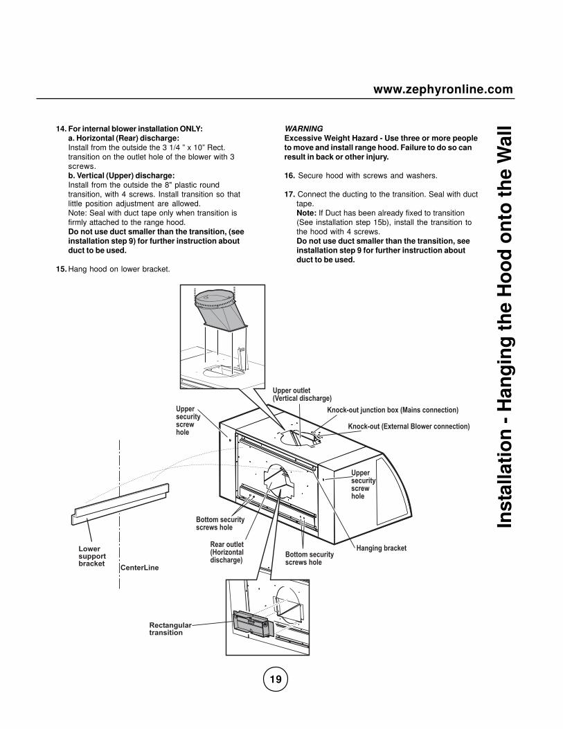
l14. For internal blower installation ONLY:a. Horizontal (Rear) discharge:Install from the outside the 3 1/4 ” x 10” Rect.transition on the outlet hole of the blower with 3screws.b. Vertical (Upper) discharge:Install from the outside the 8" plastic roundtransition, with 4 screws. Install transition so thatlittle position adjustment are allowed.Note: Seal with duct tape only when transition isfirmly attached to the range hood.Do not use duct smaller than the transition, (seeinstallation step 9) for further instruction aboutduct to be used.
15. Hang hood on lower bracket.
WARNINGExcessive Weight Hazard - Use three or more peopleto move and install range hood. Failure to do so canresult in back or other injury.
16. Secure hood with screws and washers.
17. Connect the ducting to the transition. Seal with ducttape.Note: If Duct has been already fixed to transition(See installation step 15b), install the transition tothe hood with 4 screws.Do not use duct smaller than the transition, seeinstallation step 9 for further instruction aboutduct to be used.
�+�,�-./0+/( -, A-�/�03 425�,6+)
�**+,�-./0+/(1+,/ 2�0�3 425�,6+)
$�-27�-./�B.�2/ -��9-��(:� �4�2-��+2/ -�)
$�-27�-./�("�/+,��0�&0-;+,�2-��+2/ -�)
��6 �6�9,�27+/&-//-��4+2., /=42,+;4�5-0+
&-//-��4+2., /=42,+;4�5-0+
�**+,4+2., /=42,+;5-0+
�**+,4+2., /=42,+;5-0+
%�� #�"���#��#��! �
� �� #%��
, �����"$�#�#��������

20
Inst
alla
tio
n -
Ele
ctri
cal C
on
nec
tio
n &
Fin
al In
stal
lati
on
Ste
ps
18. Electrical connection
WARNINGElectrical Shock HazardWarning: Turn off power circuit at the service panelbefore wiring this unit.120 VAC, 15 or 20 Amp circuit required.
ELECTRICAL GROUNDING INSTRUCTIONSTHISAPPLIANCE IS FITTED WITH AN ELECTRICALJUNCTION BOX WITH 3 WIRES, ONE OF WHICH(GREEN/YELLOW) SERVES TO GROUND THEAPPLIANCE. TO PROTECT YOUAGAINSTELECTRIC SHOCK, THE GREEN AND YELLOWWIRE MUST BE CONNECTED TO THE GROUNDINGWIRE IN YOURHOME ELECTRICAL SYSTEM, AND IT MUST UNDERNO CIRCUMSTANCES BE CUT OR REMOVED.Failure to do so can result in death or electricalshock.
Install the conduit connector (cULus listed) injunction box.
Run 3 wires; black, white and green, according to theNational Electrical Code and local codes andordinances, in 1/2" conduit from service panel tojunction box.
8�&-��2-@+,
�-�3. /
Connect black wire from service panel to black or redin junction box, white to white and green to green-yellow.
Close and secure junction box cover.
19. Note: disregard this step if the hood has been fittedwith an internal blower.Purchase and install an External blower (Seeparagraph „Before installing the hood - Parts notsupplied“ for model reference).
20. Check all light bulbs to make sure they are securein their sockets.
21. Install the internal left-right side covers (Seechapter "Installation-preliminary operations")
22. Install filters.
23. Install the lower section of the Duct Cover (StartingCollar) with 2 screws and slide it towards the top ofthe hood.Turn power (On) in service panel.Check lights and blower operation.
If range hood does not operate:• Check that the circuit breaker is not tripped or the
house fuse blown.• Disconnect power supply. Check that wiring is
correct.

21
www.zephyronline.com
Des
crip
tio
n o
f th
e H
oo
d1 Controls2 Baffle filter3 Halogen lamp4 Incandescent ambient lamp5 Hood body6 Duct cover
�
�� �
8
�
9

22
Fea
ture
s &
Co
ntr
ols
- To
uch
Co
ntr
ols
& F
eatu
res Use the high suction speed in cases of concentrated kitchen vapors. It is recommended that the cooker hood suction is
switched on for 5 minutes prior to cooking and to leave in operation during cooking and for another 15 minutes afterterminating cooking.Note: Hood retains last speed setting when aspiration switch is turned off.
Description of control panel:
1. Blower On/Off
By pressing ,the blower is switched On and Off.
2. Speed SelectionThe 3 speed levels are selected by pressing to decrease and to increase speed level.The display indicates level selected.
3. Delay OffThis is used for programmed shut down of blower and lights 15 minutes after the function is activated.
Press once,a dot flashes in the lower right hand side of display indicating the function is on.The hood will completely shut down in 15 minutes.
4. Lights On/Off/DimSwitch lights On and Off by pressing once.To dim lights,press and hold it in for 2 seconds.
5. Advance Display Functions
6. Mood Light On/OffThis switch turns the mood lights On and Off.Press IN to turn on,press again to turn OFF.Filters Clean Reminder (Metal):
� 9
�
8
�
&0-;+,�����<< � 4*0�=���� ��� � ���� ��������������������� ���� ��
�3B.4/���*++3�#+@+04:--3�# 65/�����<<
# 65/4�����<<� -03�/-�� �
���: ���+0�=��??

23
www.zephyronline.com
Filter Clean Reminder (Standard Baffle Filters fitted):
A set of baffle filters are fitted by the factory. These Baffle Filters are intended to filter out residue from cooking. They
need not be replaced on a regular basis but are required to be kept clean. The Filter Clean Reminder function inthe microprocessor will automatically indicate by a flashing when the metal filters need to be cleaned afterevery 30 hrs. of use. Filters can be cleaned by hand with non-abrasive soap or in a dishwasher.
Filter Clean Reminder:
When flashes on display, the baffle filters installedare required to be cleaned.This will occur after every 30 hours of use.
Re-setting Function:
Reset the Filter Clean Reminder timer when filters arecleaned and re-installed (with hood off).
Press and hold for approx. 5 seconds, the display willappear; hold for approximately 5 seconds until ondisplay disappears .The Filter Clean Reminder function is now re-set and anew 30 hours elapse cycle is initiated.
Clean Filters
display <A> flashes
To Reset
display from <A> to < >hold 5 secs.
Fea
ture
s &
Co
ntr
ols
- T
ou
ch C
on
tro
ls &
Fea
ture
s

24
Mai
nte
nan
ce
BAFFLE FILTER
This must be cleaned once a month using non abrasi-ve detergents, either by hand or in the dish-washer,which must be set to a low temperature and a shortcycle.When washed in a dish-washer, the baffle filter maydiscolor slightly, but this does not affect its filteringcapacity.To remove the baffle filter, pull (a) the handle and extractthe filters (b).
REPLACING THE HALOGEN LIGHT BULB:
WARNINGDisconnect the hood from electricity and be sure thelights are cool.
If new lights do not operate, make sure the light bulb isinserted correctly before calling service.
• Remove bulb by pressing both ends of the metalretaining clip together, the light socket will nowprotude from the hood allowing you to remove thebulb.(Be careful when releasing retain clip as it is underpressure to hold it in place)
• Replacement halogen bulbs are available at moststores which sell light bulbs. Purchase type GU-10,120V, 50W. Follow package directions.
• Reinstall the metal retaining.
ATTENTION!
Prior to any maintenance operation ensure that the cooker hood is disconnected from the power supply.
CLEANING
The cooker hood should be cleaned regularly internally and externally.Use a cloth moistened with a neutral liquid detergents. Avoid abrasive detergents.Warning:Failure to carry out the basic cleaning recommendations of the cooker hood and replacement of the filters may cause firerisks.Therefore, we recommend oserving these instructions.
a
a
b
b
metalretaining

25
www.zephyronline.com
Mai
nte
nan
ce
REPLACING THE MOOD LIGHTING BULB:
To replace mood lighting bulb, remove baffle filter fromhood.To access lamp area, remove the two threaded knobsthat fix the cover.Unscrew mood lighting bulb counter-clockwise andreplace with a standard max. 40W, type T10, 125V-130Vmedium base bulb.

26
Tro
ub
le S
ho
oti
ng
After installation, theunit doesn’t work?
Light works, but motoris not turning.
The unit is vibrating.
The motor is working,but the lights are not.
The hood is not ventingout properly.
Metal filter is vibrating.
1. The power source is not turned ON.
2. The power line and the cable lockingconnector is not connecting properly.
3. The switch board and control boardwirings are disconnected.
4. The switch board or control board isdefective.
1. The motor is defective, possibleseized.
2. The thermally protected systemdetects if the motor is too hot tooperate and shuts the motor down.
3. Damaged condenser.
1. The motor is not secure in place.
2. Damaged blower wheel.
3. The hood is not secured in place.
1. Defective halogen bulb.
2. The light bulb is loose.
1. The hood might be hanging to highfrom the cook top.
2. The wind from the opened windowsor opened doors in the surroundingarea are affecting the ventilation ofthe hood.
3. Blocking in the duct opening orductwork.
4. The direction of duct opening isagainst the wind.
5. Using the wrong size of ducting.
1. Metal filter is loose.
Issue Cause What to do
1. Make sure the circuit breaker and theunit’s power is ON.
2. Check the power connection with theunit is connected properly.
3. Make sure the wirings between theswitch board and control board areconnected properly.
4. Change the switch board or controlboard.
1. Change the motor.
2. The motor will function properly afterthe thermally protected system cooldown.
3. Change the condenser.
1. Tighten the motor in place.
2. Change the blower wheel.
3. Check the installation of the hood.
1. Change the halogen bulb.
2. Tighten the light bulb.
1. Adjust the distance between the cooktop and the bottom of the hood within24” and 32” range.
2. Close all the windows and doors toeliminate the outside wind flow.
3. Remove all the blockage from the ductwork or duct opening.
4. Adjust the duct opening direction.
5. Change the ducting to at least 8” orhigher.
1. Change the metal filter.

27
www.zephyronline.com
Lis
t of P
arts
an
d A
cces
sori
es
Part Description Part#
Internal Blower 600 CFM
External Blower 1000 CFM
Halogen Bulb, 120V 50 W
Filter Baffle
Z0B0020S
EBI-600B
CBE-1000
Front Panel 42" SS CPC-0012
Front Panel 42" Brass CPC-0112
Front Panel 48" SS CPC-0018
Front Panel 48" Brass CPC-0118
Front Panel 54" SS CPC-0015
Front Panel 54" Brass CPC-0115
50210002
Doluflex 6pc. Blank, 42" CDO-0042
Doluflex 6pc. Blank, 48" CDO-0048
Doluflex 6pc. Blank, 54" CDO-0054
Veneer, 6pc. Copper, 42" CDO-0142
Veneer, 6pc. Copper, 48" CDO-0148
Veneer, 6pc. Copper, 54" CDO-0154
Veneer, 6pc. Stainless, 42" CDO-0242
Veneer, 6pc. Stainless, 48" CDO-0248
Veneer, 6pc. Stainless, 54" CDO-0254
Part Description Part#