packaged electric cooling/gas heating 100% …partscounter.us-ac.com/reznor/reznor literature...
TRANSCRIPT

Form RGM-414 Page 1
I. GENERAL DESCRIPTION
Unpacking ............................................................................... 2
Design Certification ................................................................ 2
Codes and Ordinances ............................................................ 2
Cooling Section .................................................................... 2-3
Gas Furnace Section ............................................................... 3
II. INSTALLATION
Clearances ............................................................................... 6
Setting the Unit ....................................................................... 3
Electrical .............................................................................. 3-4
Gas Piping ........................................................................... 4-5
Venting ................................................................................. 5-6
Condensate Piping .................................................................. 6
III. SEQUENCES OF OPERATION
General System Sequence of Operation ................................. 7
Mechanical Cooling ................................................................ 7
Gas Heat ................................................................................. 7
Electronic Proven Pilot Spark Ignition Control ...................... 7
Series 21/31 Maxitrol Regulator ............................................. 8
Variable Speed Fan Motor and Control .................................. 8
Optional Hot Gas Reheat ....................................................... 8
Optional Reheat Plus .............................................................. 8
Optional Motorized Outside Air Damper ............................. 8
Optional Clogged Filter Indicator ........................................... 8
IV. CHECK–TEST–START–SERVICE–MAINTENANCE
A. General ............................................................................ 9
Contractor Responsibility .............................................. 9
Suggested Test and Maintenance Tools ......................... 9
B. Inspection ....................................................................... 9
Model Designation Chart ............................................. 10
Pre-Start-up Precautions .............................................. 11
Electrical Data Chart ..................................................... 12
IV. CHECK–TEST–START–SERVICE–MAINTENANCE(Continued)
C. Control System ............................................................. 13
D. Evaporator Blower ....................................................... 13
Blower Performance Chart ........................................... 14
E. Gas Furnace
Gas Pressures and Regulator Adjustments ................... 15
Typical Wiring Diagram .......................................... 16-17
Refrigeration Piping Diagram ........................................ 18Pilot Flame Adjustment ................................................. 19
Firing Sequence ............................................................ 19
Limit Control ................................................................. 19
Combustion Air Proving Switch ................................... 19
F. Field Adjustable Controls
Component Location Guide .......................................... 20
Refrigeration Circuit Controls ....................................... 20
Adjustable Ambient Thermostat .................................... 20
Hot Gas Bypass ............................................................ 21
Hot Gas Reheat ............................................................. 21
Cylinder Unloader Pressure Switch .............................. 21
Variable Speed Condenser Head Pressure Control .. 21-22
Gas Furnace Controls ................................................... 22
G. Trouble-Shooting Guides ......................................... 24-31
General Refrigeration Circuit ................................... 24-26
Variable Speed Condenser Head Pressure Control ....... 26
Hot Gas Bypass Regulator ............................................ 27
General Gas Furnace ..................................................... 28
Ignition Control ............................................................. 29
Maxitrol-Regulator ................................................... 30-31
Applies to: Reznor® Models PCCH and PCCR
R
Table of Contents
For more specific information relating to Duct Furnace Heating Component,
refer to Installation/Operation/Maintenance Manual RGM-401
KEEP THIS BOOKLET
FOR MAINTENANCE AND
SERVICE REFERENCE.
FOR YOUR SAFETY
WARNING: The use and storage of gasoline or other flam-
mable vapors and liquids in the vicinity of this appliance is
hazardous.
WARNING: Improper installation, adjustment, alteration,
service or maintenance can cause property damage, injury
or death. Read the installation, operation and maintenance
instructions thoroughly before installing or servicing this
equipment.
If you smell gas:
1. Open windows.
2. Don’t touch electrical switches.
3. Extinguish any open flame.
4. Immediately call your gas supplier.
®LISTED
PACKAGED ELECTRIC
COOLING/GAS HEATING
100% OUTSIDE MAKEUP AIR(Specifications subject to change without notice.)
Installation/Operation/Maintenance /Service Form RGM-414
NEW

Form RGM-414 Page 2
2. Model DesignationThis packaged unit is shipped fully assembled and factory tested. It isgenerally installed on a steel roof mounting curb assembly which has beenshipped to the job site for installation on the roof structure prior to the arrivalof the unit, or on an appropriate ground level concrete pad.
The model number shown on the unit identification plate identifies the unitby Application, Cooling Capacity (Nominal MBH) and Gas heating byInput (MBH). See chart to right.
3. UnpackingWhen received, the unit should be checked for damage that might haveoccurred in transit. If damage is found, it should be noted on the carrier’sFreight Bill. Request for inspection by carrier’s agent should be made inwriting at once.
4. Design CertificationAll units are certified by Electrical Testing Laboratories (E.T.L.), underANSI/UL 1995. The furnace designs are certified by American GasAssociation (A.G.A.) under ANSI Z83.9 (latest edition) for use withnatural gas only.
! WARNINGThis unit contains chlorodifluoromethane (HCFC-22), a substance that harms public health and environment bydestroying ozone in the upper atmosphere.Do not vent HCFC-22 to the atmosphere. The U.S. Clean Air Act requires the recovery of any residualrefrigerant.
1. General DescriptionEach Model Series packaged makeup air unit is designed to cool and heat100 percent outside air year round. Outdoor air can be hot and humid, sothe airflow must be reduced to less than half the cfm per ton of aconventional air conditioner. This reduced airflow ensures proper mois-ture removal. At higher wet bulb temperatures more than twice the amountof condensate is produced, and the lower airflow prevents condensate carryover. At lower ambient temperatures, the supply air is heated and thetemperature is maintained by modulating the indirect fired gas heat asneeded.
These units may be roof mounted on a factory supplied roof curb, slabmounted, or installed on post and rails. Air is drawn into the outside airintake located on the end of the unit and through metal mesh filters beforeentering the evaporator coil and heat exchanger.
Every unit is charged with refrigerant and run tested in both cooling andheating modes before shipment.
Heating InputNominal Max
Model Nominal Cooling (MBH)
Sizes CFM (MBH) Single/Dual
071 1,200 70.6 125
101 1,500 101.1 175
141 2,000 135.3 225 / 450
181 2,500 180.8 300 / 600
201 3,000 201.7 350 / 700
271 4,000 271.2 400 / 800
361 5,000 339.0 400 / 800
412 6,000 370.0 400 / 800
Standard Sizes
Code Application
PCCR 100% Outside AirRooftop Model
PCCH 100% Outside AirHorizontal Discharge
071 70.6
101 101.1
141 135.3
181 180.8
201 201.7
271 271.2
361 339.0
Code
Nom.
MBH
Cooling
100 100,000 80,000 071 - 101
125 125000 100000 071 - 271
150 150000 120000 101 - 361
175 175000 140000 101 - 361
200 200000 160000 141 - 361
225 225000 180000 141 - 361
250 250000 200000 181 - 361
300 300000 240000 181 - 361
350 350000 280000 271 - 361
400 400000 320000 361
High OutputInput Capacity Models
Code BTUH BTUH Used With
Heating
PCCR 141 225
Model Designation Chart
5. Codes and OrdinancesThese units must be installed in accordance with the standard of the NationalFire Protection Association or the National Fuel Gas Code ANSI Z83.9(latest edition). The National Fuel Gas Code is available from the AmericanGas Association, 1515 Wilson Boulevard, Arlington, VA 22209. NFPAPublications are available from the National Fire Protection Association,Batterymarch Park, Quincy, MA 02269. Local authorities having jurisdic-tion should be consulted before installations are made to verify local codesand installation procedures.
All field wiring to the unit must be done in accordance with theseinstructions, the National Electric Code (ANSI/NFPA 70-1981) and alllocal codes and ordinances.
Clearances from the heater and vent to construction or material in storagemust conform with the National Fuel Gas Code ANSI Z83.9 (latestedition), pertaining to gas-burning devices, and such material must notattain a temperature over 160°F by continued operation of the heater.

Form RGM-414 Page 3
The internal systems of the unit are completely factory installed and testedprior to shipment and no additional field labor is required.
9. ClearancesAdequate clearance around the unit must be kept for safety, accessibility,service, and maintenance. 48 inches clearance is required on the rear(furnace and electrical) end of the unit. This clearance must be maintainedfor compressor removal and in the case of a furnace unit, for removal ofthe furnace and to insure proper flue gas flow. All combustible materialsmust be kept out of the area. A 48 inch clearance is also required on the front(outside air) end of the unit for blower removal and for adequate outsideair accessibility. The clearance of 96 inches on the filter access side of theunit is required for blower shaft removal and 36 inches is required on thecondenser side for an adequate supply of condenser air.
Required Clearances
Provide minimum clearance as shown for safety, clearance from combus-tibles, and for service.
10. Setting the Unit
CAUTION: Units may look identical but have significantinternal differences. Check specific unit location carefully (refer-ring to plans if necessary) prior to setting unit.
Installation should be done by a qualified agency in accordance with theinstructions in this manual and in compliance with all codes and require-ments of authorities having jurisdiction.
6. Cooling Section
Compressor
High efficiency scroll and serviceable-hermetic discus compressors havebeen selected for their refrigeration reliability in these units. Compressormountings are designed to minimize vibration and piping stress. Service-able-hermetic models use special waffle pad isolator and washers. Allcompressors have hot gas bypass capacity reduction: serviceable-hermeticcompressors also have cylinder unloading.
Compressor Protection
All compressors have crankcase heaters and the motors are equipped withinternal overload protection. The serviceable-hermetic compressors arealso equipped with isolation valves and oil pressure failure protection.
Coil
The condenser and evaporator coils are aluminum plate-finned, formed onmultiple rows of seamless copper tubing arranged in a staggered-tubeconfiguration. The tubes are mechanically expanded, firmly bonding thetube to the shoulder of each fin.
Refrigerant Circuit
Included in the refrigerant circuit is an accumulator, filter-drier, high-pressure safety control (manual reset), low-pressure safety control/loss ofcharge protector (auto reset), gauge port connections for high and lowpressure readings, sight-glass moisture indicator, and thermostatic expan-sion valve. The expansion valve has adjustable superheat and distributorsto meter the refrigerant evenly to the evaporator refrigerant circuits.
Condenser Air Fan and Motor
The condenser air fan is of the propeller type, electronically balanced, anddirect-driven by a 1075 rpm Permanent Split Capacitor fan motor. Theinherent protected motor has sealed ball bearings that do not requirelubrication. The outdoor air is discharged through a vinyl-coated fan guard.This directs all sounds upward, eliminating the effects of wind directionand minimizing condenser airflow sound projection.
Blower and Motor
A forward curved, statically and dynamically balanced DIDW centrifugalblower is used for the indoor air. The blower wheel and housing arecorrosion protected. The blower wheel is mounted on a solid steel shaftsupported by sealed ball bearings. The shaft is driven by adjustable belt-driven sheaves, connected to a 1725 rpm motor with sealed ball bearings.The sealed bearings on both the blower shaft and motor do not requirelubrication. Motors through 3 horsepower are internally protected (autoreset) and motors 5 horsepower and larger are externally protected (manualreset).
7. Gas Furnace SectionThis unit is equipped with an indirect gas-fired furnace which is 80 percentthermal efficient. All units are equipped for natural gas and include anintegral power-vent system which provides metered combustion air,dilutes flue products, and eliminates the need for a vent cap. Combustionair intake and flue outlet locations are on same side of the unit. Each unithas all the required limit and safety controls, including a venter pressureswitch which verifies power vent operation prior to allowing operation of24-volt gas valve.
8. ConnectionsThe installation of packaged units consists of making final connectionsbetween the unit and building services such as electrical power supply,natural gas, supply and return duct connections, and drain connections.
Top 36”
Control Side 48”
All Other Sides 36”
Note: A clearance of 100” is suggested on the side opposite thecondenser should it become necessary to remove the fan shaft.
Curb Installation
Proper installation requires that the roof mounting curb be firmly andpermanently attached to the roof structure. Check for adequate fasteningmethod prior to setting rooftop unit on curb.
Protrusions
Inspect curb to insure that none of the utility services (electric, gas, drainlines) routed through the curb protrude above the curb. Duct connectionswill normally be made after unit is set on curb. If duct is prefabricated andinstalled within the curb prior to setting unit, insure that duct work doesnot protrude above curb.
DO NOT ATTEMPT TO SET UNIT ON CURB IF PROTRUSIONSEXIST.
Unit Installation
Lower unit carefully onto roof mounting curb or mounting rails or groundlevel slab. While rigging unit, center of gravity will cause condenser endto be lower than supply/return air end. Bring condenser end of unit intoalignment with curb. With condenser end of unit resting on curb memberand using curb as fulcrum, lower front end of unit until entire unit is seatedon curb.
Rigging Removal
Remove spreader bars, lifting cables and other rigging equipment.
CAUTION: Do not allow crane hooks and spreader barsto rest on roof of unit.

Form RGM-414 Page 4
WARNING
CAPACITY OF PIPINGCubic Feet per Hour Based on 0.3" W.C. Pressure Drop
Specific gravity for Natural Gas – 0.6 (1000 BTU/Cubic Foot)
Lengthof
PIPE 1/2" 3/4" 1" 1-1/4" 1-1/2" 2"
20' 92 190 350 730 1,100 2,100
30' 73 12 285 590 890 1,650
40' 63 130 245 500 760 1,450
50' 56 115 215 440 670 1,270
60' 50 105 195 400 610 1,105
70' 46 96 180 370 560 1,050
80’ 43 90 170 350 530 990
90' 40 84 160 20 490 930
100' 38 79 150 305 460 870
125' 34 72 130 275 410 780
150' 31 64 120 250 380 710
175' 28 59 110 225 350 650
200' 26 55 100 210 320 610
NOTE: When sizing supply lines, consider possibilities of futureexpansion and increased heating requirements.
See National Fuel Gas Code for additional information on supply pipesizing.
WARNINGGas-fired appliances are not designed for use inhazardous atmospheres containing flammable vaporsor combustible dust, in atmospheres containingchlorinated or halogenated hydrocarbons, or inapplications with airborne silicone substances.Improper installation, adjustment, alteration, service,or maintenance can cause property damage, injury, ordeath. Read the installation, operation, andmaintenance instructions thoroughly before installingor servicing this equipment.
!11. Electrical
Wiring Connections
Power wiring should be connected to the main power terminal blocklocated within the unit main control section. Power wiring connectionson units with factory disconnects should be made at the line side of thedisconnect switch.
Low voltage wiring connections are made to the remote mountedcontroller or time clock.
Do Not Tamper with Factory Wiring
Contact your local representative or the factory if assistance is required.The internal power and control wiring of these units is factory installedand each unit is thoroughly tested prior to shipment.
Independent Power Source
It is recommended that an independent 115 volt power source be broughtto the vicinity of the rooftop unit for portable lights and tools used by theservice mechanic.
When providing or replacing fuses in a fusible disconnect switch, use dualelement time delay fuses and size 1.25 times the maximum total inputamps as stated on the unit rating plate.
Main Power Wiring
The units are factory wired for the voltage shown on the nameplate.
Main power wiring should be sized for the minimum wire ampacity shownon the nameplate.
An external weather-tight disconnect switch properly sized for the unit totalload is required for each unit. Disconnect must be installed in accordancewith Local and/or National Electric Codes.
Power wiring may enter the Rooftop Unit through the side on all models,or through the unit base and roof curbs on models with the Power ThroughCurb option. Install conduit connectors at the entrance locations. Externalconnectors must be weatherproof.
Grounding
All units must be properly grounded. The ground lug is provided for thispurpose. DO NOT use the ground lug for connecting a neutral conductor.The unit must be electrically grounded in accordance with local codes, orin the absence of local codes, with the NEC ANSI/NFPA 70 1981.
Low Voltage Control Wiring
Remote Control
The MC20 controller may be shipped loose to accommodate remotemounting. Cable connections are facilitated by use of standard barrierterminal strip and spade terminal connections for easy installations.
Follow the installation and wiring instructions supplied with the MC20controller. Low voltage wiring may be NEC Class II when permitted bylocal codes.
DDC Controls
If a multifunction direct digital controller is factory installed or remotemounted it would provide a complete operating and monitoring system.(Refer to the DDC Controls Specification Sheet)
12. Gas Piping
For Your Safety
The use and storage of gasoline or other flammable vapors and liquids inopen containers in the vicinity of this appliance is hazardous.
Gas Piping
Sizing Gas Supply Lines
All piping must be in accordance with requirements outlined in theNational Fuel Gas Code ANSI/Z223.1a (latest edition), published by theAmerican Gas Association. Gas supply piping installation shouldconform with good practice and with local codes.
Pipe joint compounds (pipe dope) must be resistant to the action ofliquefied petroleum gas or any other chemical constituents of the gas beingsupplied.
Install a ground joint union and manual shut-off valve upstream of the unitcontrol system, as shown in the above illustration. The 1/8" pluggedtapping in the shut-off valve provides connection for supply line pressuretest gauge. The National Fuel Gas Code requires the installation of a trapwith a minimum 3" drip leg. Local codes may require a minimum drip leglonger than 3" (typically 6").

Form RGM-414 Page 5
After all connections are made, disconnect the pilot supply at the controlvalve and bleed the system of air. Reconnect the pilot line and leak-test allconnections by brushing on a soap solution.
Install the gas supply piping so that when the union is disconnected, thesupply pipe will not interfere with the removal of the burner rack. Theburner rack slides out of the control side of the furnace.
This appliance is equipped for a maximum gas supply pressure of 1/2pound, 8 ounces, or 14 inches water column. Supply pressure higher than1/2 pound requires installation of an additional service regulator externalto the unit.
Nipple Nipples
ElbowsGround
Joint UnionShut-Off Valve
Minimum 1” clearance between heateraccess panel and elbow or fitting
A manual shut off valve with 1/8”N.P.T. plugged tapping. Accessiblefor test gage connection must beinstalled immediately upstreamof the gas supply connectionto the appliance
Gas Connection – All Models
3 in.minimum
Riser
Gas Valve
Horizontal
3 in.minimum
Gas Valve
Piped GasSupply
Drop
Piped GasSupply
Tubing GasSupply
Gas Valve3 in.minimum
Riser
Drop
Horizontal
Typical Gas Valve Piping
NOTE:ALWAYS INCLUDE ADRIP LEG IN PIPING
Flue Products
Combustion Air Intake
Make GasConnectionHere
Flue Gas and Combustion Air Openings
WARNING
All components of a gas supply system must be leaktested prior to placing equipment in service. NEVERTEST FOR LEAKS WITH AN OPEN FLAME.Failure to comply could result in personal injury,property damage or death.
!
Pressure Testing Supply Piping
Test Pressures Above 1/2 PSI: Disconnect the heater and manual valvefrom the gas supply line which is to be tested. Cap or plug the supply line.
Test Pressures Below 1/2 PSI: Before testing, close the manual valve onthe heater.
13. VentingFlue Gas and Combustion Air Openings
These screened openings are located on the side of the furnace just abovethe control access panel. The positions of these openings discouragesrecirculation of combustion products and provides for furnace operationin all normal weather conditions. See the illustration below.
Chlorines — All Models
The presence of chlorine vapors in the combustion air of gas-fired heatingequipment presents a potential corrosion hazard. Chlorine will, whenexposed to flame, precipitate from the compound, usually refrigerant ordegreaser vapors, and go into solution with any condensation that is presentin the heat exchanger or associated parts. The result is hydrochloric acidwhich readily attacks all metals including 300 grade stainless steel.
Care should be taken to separate these vapors from the combustion process.This may be done by wise location of the furnace with regard to exhaustersor prevailing wind direction. Remember, chlorine is heavier than air. Thisfact should be kept in mind when determining installation locations ofheating equipment and building exhaust systems.
Venting Requirements
Locate power-vented furnaces so that flue discharge is not directed at freshair inlets.
These power vented furnaces are certified with four feet of vertical pipeattached as shown in the following illustration. The distance is measuredfrom the top of the unit to the bottom of the vent cap. The option packageincludes the 5 inch vent cap, the adapter assembly, and the seal plate. Thevent pipe and supports are field supplied.
Optional vertical vent piping provides compliance with local codes thatrequire either 10 foot horizontal or 4 foot vertical clearance between the flueoutlet and fresh air intake of the heating system and/or the building.

Form RGM-414 Page 6
15. Sequence of OperationGeneral System Sequence of Operation (refer to unitwiring diagrams)
1. When electric power is applied to the unit, the 24 volt transformer isenergized.
Time delay begins (set at five minutes from the factory, field adjustablefrom 6 seconds to 8 minutes). Upon completion of the delay periodthe coil of the slave relay is energized, closing its N.O. contacts. Thismakes a circuit through the normally closed high pressure cutout,compressor motor protection module if applicable, and through theoil failure cutout to the low pressure control. The N.O. contacts of theslave relay close making a line voltage circuit to the N.O. contacts ofthe cooling pilot relay. At the same time, the crankcase heaters areenergized.
2. On a call for system operation the field installed system switch isclosed, and a control circuit is made.
3. The coil energizes the blower pilot relay which closes its N.O.contacts, energizing the coil of the evaporator blower motor contactorwhich in turn closes its line voltage contacts and energizes theevaporator blower motor also making a line voltage power supply tothe gas furnace.
4. As the evaporator blower motor contactor closes, it causes a 24 voltcontrol circuit to terminal “R” of the compressor lockout thermostat“CLT” and gas furnace.
5. If the outdoor ambient temperature is above the set point of 65° F, thecoil of the cooling pilot relay causes its N.O. contacts to close, makinga line voltage circuit across the coil of the liquid line solenoid valve.
As the refrigerant pressure increases and closes the low pressurecontrol, a line voltage circuit is made to the time delay. Uponcompletion of the delay period the coil(s) of the compressor contactor(s)are energized, causing the contactor to close and energize thecompressor.
A line voltage circuit is also made to the unloading pressure control.If it is closed, a circuit is made to the coils of the unloader solenoidand the hot gas bypass solenoid valve.
When the compressor contactor closes, it also closes the compressorcontactor auxiliary making a circuit to the coil of the condenser fancontactor and through low ambient fan controls to the coils ofcondenser fan contactors.
If the outdoor ambient temperature is below the set point of 65° F, theN.C. contacts of the compressor contactor auxiliary energizes the coilof the interlock relay causing its N.O. contacts to close in the gasfurnace control circuit. NOTE: The compressor contactor auxiliary“CC2A” can only be closed if the compressor contactor is open,therefore the interlock relay prevents the simultaneous operation ofthe compressor and gas furnace.
On a call for heat, a control circuit is made to energize the coil of theheat relay. The main blower proving switch will close when airflowis present.
The furnace section is made from the control terminal across the N.C.contacts of the combustion pressure switch, energizing pilot ignitiontime delay relay heater. After delay of approximately 30-50 secondsthe time delay relay’s switch closes energizing the furnace ventermotor. As the venter operates, it causes the combustion pressureswitch to open. The ignition control energizes a high voltage electricspark, and the pilot valve solenoid in the combination gas valve.
The flame sensor proves the presence of the pilot flame generating aDC current of 0.2 microamp (or greater) to the ignition control. Theignition control’s internal switch action then de-energizes the sparktransformer and makes a circuit to the high fire solenoid of thecombination gas valve.
When there is a call for gas furnace operation the discharge airtemperature causes a change in the resistance of a discharge air sensorthermistor. The Maxitrol solid state control center measures thesensor’s change in resistance and sends a varying DC current to theModulator-Regulator valve to adjust the gas input as required.
6”
3”
3/4 FPTFROM UNIT
The Trap must be primed before operating unit.
Drain Trap
14. Condensate PipingA condensate trap must be provided by customer. Drainage of condensatedirectly onto the roof is acceptable if permitted by local codes. It isrecommended that a small drip pad of either stone, mortar, wood or metalbe provided to prevent any possible damage to the roof. If condensate isto be piped into the building drainage system, the drain line must penetratethe roof external to the unit. Refer to local codes for additional requirements.
WARNINGThis furnace is not A.G.A certified or C.G.A.approved for use in drying or process applications. Ifthe unit is to be used in a drying or process application,contact the factory for application guidelines andmanufacturer’s authorization. Without factoryauthorization, the warranty is void, and themanufacturer disclaims any responsibility for thefurnace and/or the application.
!
Vertical Vent
5" Vent Cap
5" Dia. – Flue Pipe
FRONTVIEW
Oval AdapterAssembly
5" 90° Elbow
Combustion Air Intake
The straight pipe connecting the furnace to the 90° elbow must be atleast 12" in length.
4'0"
Installation of the Vent Cap (included in the option package) and thefield-supplied Piping and Supports

Form RGM-414 Page 7
Mechanical Cooling
The compressor starts when the outside air temperature is above theadjustable setpoint. In the cooling mode the leaving air temperature will bemaintained by hot gas bypass and/or unloading the compressor. This isaccomplished through suction-pressure sensing, thus tracking the outsideair temperature variations.
Gas Heat
In the heating mode the leaving air temperature will be maintained by amodulating gas regulator in response to the leaving air temperature setpoint.
When the leaving air temperature drops below the leaving air sensor setpoint, the venter motor is energized after 15-seconds (approximate) timedelay. Venter flow causes switching from N.C. to N.O. contacts, energiz-ing the pilot gas valve and spark gap to produce a pilot flame on eachoperating cycle. The sensing probe proves the presence of the pilot flameand energizes the safety switch portion of the control. The switch actionde-energizes the spark gap and energizes the main valve. The main gasignites and the unit fires at full rate. If the flame is extinguished during mainburner operation, the safety switch closes the main valve and recycles thespark gap.
Electronic Proven Pilot Spark Ignition Control
When there is a call for heat, the electric spark and pilot valve areautomatically energized to produce a pilot flame on each operating cycle.The flame sensor proves the presence of the pilot flame; internal switchaction de-energizes the spark transformer and energizes the main burnerelectric valve. The main gas ignites and the heating cycle is in normaloperation. When the call for heat is satisfied, the main burner valve and thepilot valve are de-energized.
15. Sequences of operation
Series 21/31 Maxitrol Regulator
This unit may be equipped with electronic modulation that will providefiring rate of 100% down to 50%, depending on the heat requirements asestablished by the thermistor sensor. The thermistor is a resistor thatchanges its resistance depending upon the surrounding temperature. Thischange in resistance is monitored by the solid state control center which,in addition to opening and closing the main valve, will furnish varying DCcurrent to the modulating valve to adjust the gas input as required. Themodulating valve is basically a regulator with electrical means of raisingand lowering the discharge pressure. When no DC current is fed to thisdevice, it becomes a gas pressure regulator, supplying 3.5"w.c. pressureto the main operating valve and the burners.
Condenser Fan Motor and Control
A variable speed fan motor and control is standard with all reheat optionsbecause units operating in low ambient temperature require a controlsystem to maintain stable head pressure. Head pressure control is accom-plished with one or two variable speed condenser fan drives. A pressuresensing control modulates the condenser fan speed as required to maintainhead pressure between 190 psig and 250 psig.
Sizes 071, 101 and 141 — are equipped with one variable speed motor andcontrol.
Sizes 181, 201 and 271 — are equipped with one single phase variablespeed motor and one 3 phase motor (dual fan units).
The size 361 is equipped with one variable speed motor and three 3 phasemotors (four fan unit).
This pressure sensing system consists of a variable speed motor driven fanand a constant speed motor driven fan. Both are controlled from refrigerantpressure rather than ambient temperature, reflecting actual operatingconditions in the machine.
At low ambient, the variable speed fan operates, increasing in speed untilmaximum RPM is achieved at or around 45°F ambient. An adjustablepressure switch operates the constant speed three-phase fan set to energizethe motor at 275 psig and de-energize at 220 psig. In the ambienttemperature span of approximately 50°F to 53°F, the variable speed fanwill ramp between maximum and minimum speed while the constant speedfan cycles. The start-stop cycle varies from 45 seconds to 22 minutes duringthis period.
At 53°F, both fans are operating, the variable speed at minimum RPM andthe constant speed at full RPM. As the ambient continues to rise, the variablespeed motor increases to full speed and remains there.
If the application calls for a closer setting between maximum and minimumpressure settings on the constant speed fan, for example 275 psig on, 240psig off, the effect will be to lengthen the temperature span during whichthe cycling takes place, for example 50°F to 57°F.
40 45 50 55 60 65 70150
200
250
300
BOTH FANS ONCONTINUOUSLYWITH ONE FANVARYING SPEED.
VARIABLESPEED FANONLY
C
DUAL FAN UNIT
BOTH FANS OPERATECONSTANT SPEED FAN CYCLES
DIS
CH
AR
GE
PR
ES
SU
RE
- P
SIG
AMBIENT - °F
Optional Hot Gas Reheat
Factory installed hot gas reheat circuit includes inlet regulator valve, checkvalves, hot gas solenoid operated control valve, variable speed condenserhead pressure control, one stage sensor, and one row heat reclaim coil. Thecoil is equal to the evaporator face area and installed in the reheat position.The sensor is factory mounted. Hot gas reheat may not be operated below60°F ambient temperature.
Optional Reheat plus
To lower relative humidity (RH) in the supply air stream, a one rowsubcooling coil, generally equal to the evaporator face area may bespecified. The refrigerant liquid passes through the tube side, adding upto 40°F of subcooling. For every two degrees of subcooling, the compres-sor capacity is increased one percent. This is also reflected as an increasein efficiency. The resulting heat is passed into the air stream as reheat,usually 8°F to 10° F at 200 cfm/ton, thus the lower discharge air relativehumidity.
Optional Motorized Outside Air Damper
The damper motor and damper are factory mounted in unit and interlockedwith blower motor.
Optional Clogged Filter Indicator
Dirty or clogged filters are red flagged by an indicator when the presetpressure differential across the filters is reached. The indicator is factoryinstalled and manual-reset. It includes contacts for remote annunciation.

Form RGM-414 Page 8
16A. GENERAL
This manual has been prepared as a guide for the Check–Test–Start andmaintenance of the 100% Outside Makeup Air packaged unit.
Air balancing of duct system is not considered part of Check–Test–Startof the packaged unit. It is however, an important phase of the start-up ofany air conditioning system and should be performed upon completion ofthe Check–Test–Start procedure.
This packaged unit is designed to cool and heat 100% outside air yearround. Since outdoor air can be hot and humid, the airflow must be reducedto less than half the cfm per ton of a conventional air conditioner (see theBlower Performance chart on page 14.) This reduced airflow assuresproper moisture removal and prevents condensate carry over of theincreased volume of condensation that will be produced from the higherwet bulb temperatures. At lower ambient temperatures, the supply air isheated and the temperature is maintained by modulating the indirect firedgas heat as needed.
CONTRACTOR RESPONSIBILITY
The installing contractor must be certain that:
• All supply and return air duct work is in place and corresponds withinstallation specifications.
• All system switches, time clocks and disconnect switches aremounted and wired in accordance with installation specifications.
• The central control panel (optional equipment) is installed and wiredin accordance with installation instructions.
• The condensation trap(s) have been properly installed.
All electric power and all gas line connections must be functional andcapable of operating.
TOOLS REQUIRED TO PERFORM CHECK–TEST–START or Troubleshoot The Unit
The manufacturer of this unit recommends that the service technician haveavailable and be proficient with the following tools. This recommendationis for the minimum service tools and does not preclude additional tools andequipment:
1. Refrigeration Gauge & Manifold
2. Multimeter with the following scales:AC volts to 750DC volts to 50Resistance to 200K ohmMicro amperage
3. Clamp-On Ampmeter
4. Temperature measuring devices:
For measuring air wet bulb and dry bulb temperatures
For measuring surface dry bulb temperature
For measuring flue temperature.
5. Non-contact Tachometer
6. Manometer for verifying gas pressure 0-20" W.C.
7. Air Measuring Device
8. Refrigerant leak detector (D-Tec or equal)
9. General Refrigeration Mechanics Tools
16B. INSPECTION
Check of Roof Mounting Curb Installation
The proper installation of the unit on the roof mounting curb
should be checked. Any deficiencies observed should be noted in a separatereport and forwarded to the manufacturer. The unit and curb assembly mustbe installed level.
Check for Minimum Clearances
A minimum of 48 in. clearance must be provided on the main control boxside of the unit. A minimum of 36 in. clearance is required on all other sides.A clearance of 100 in. is desirable on the side opposite the condenser forremoval of the fan shaft.
The outside air intake must be remote from all building exhausts. Thecondenser air intake must be remote from all exhausts to assure fullcondenser capacity.
Check and Report Damage
Damaged or missing parts, if any, should be itemized in a separate reportstating what action has been initiated by the contractor to correct them. Theabsence of this information will be the basis for assuming that the unit wascomplete and in good condition on date of Check—Test—Start.
Check for Obstructions, Fan Clearance, Wiring
During the performance of the Check—Test—Start procedure you willhave occasion to work in the various sections of the unit. During theperformance of the individual checks, it is important that you removeextraneous construction and shipping materials that may be found.
All fans should be rotated manually to check for proper clearances and makecertain that they rotate freely. Bolts and screws that may have jarred looseduring shipment to the job site should be checked for tightness. All electricalconnections should be retightened.
16. Check, Test, Start-Up, Service andMaintenance
WARNINGThis unit contains chlorodifluoromethane (HCFC-22), a substance that harms public health andenvironment by destroying ozone in the upperatmosphere.Do not vent HCFC-22 to the atmosphere. The U.S.Clean Air Act requires the recovery of any residualrefrigerant.
!
16. Check, Test, Start-Up, Service andMaintenance (cont’d)
PRE-START-UP PRECAUTIONS
It is important to your safety that the unit has been properly groundedduring installation. Check ground lug connection in main control box fortightness prior to closing circuit breaker or disconnect switch.
Verify that supply voltage on line side of disconnect agrees with voltageon unit identification plate and is within the Utilization Voltage Range asindicated in the following table:
Voltage Minimum Maximum
208 187 228
230 207 253
460 414 506
System Voltage —That nominal voltage value assigned to a circuit orsystem for the purpose of designating its voltage class.
Nameplate Voltage —That voltage value assigned to a piece of equipmentfor the purpose of designating its voltage class and for the purpose ofdefining the minimum and maximum voltage at which the equipment willoperate.
Form RGM-414 Page 9
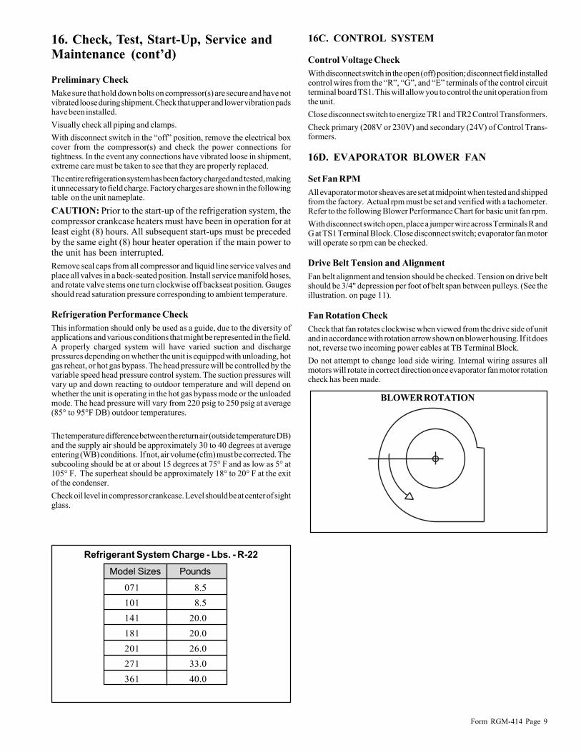
071 8.5
101 8.5
141 20.0
181 20.0
201 26.0
271 33.0
361 40.0
Model Sizes Pounds
Refrigerant System Charge - Lbs. - R-22
16. Check, Test, Start-Up, Service andMaintenance (cont’d)
Preliminary Check
Make sure that hold down bolts on compressor(s) are secure and have notvibrated loose during shipment. Check that upper and lower vibration padshave been installed.
Visually check all piping and clamps.
With disconnect switch in the “off” position, remove the electrical boxcover from the compressor(s) and check the power connections fortightness. In the event any connections have vibrated loose in shipment,extreme care must be taken to see that they are properly replaced.
The entire refrigeration system has been factory charged and tested, makingit unnecessary to field charge. Factory charges are shown in the followingtable on the unit nameplate.
CAUTION: Prior to the start-up of the refrigeration system, thecompressor crankcase heaters must have been in operation for atleast eight (8) hours. All subsequent start-ups must be precededby the same eight (8) hour heater operation if the main power tothe unit has been interrupted.
Remove seal caps from all compressor and liquid line service valves andplace all valves in a back-seated position. Install service manifold hoses,and rotate valve stems one turn clockwise off backseat position. Gaugesshould read saturation pressure corresponding to ambient temperature.
Refrigeration Performance Check
This information should only be used as a guide, due to the diversity ofapplications and various conditions that might be represented in the field.A properly charged system will have varied suction and dischargepressures depending on whether the unit is equipped with unloading, hotgas reheat, or hot gas bypass. The head pressure will be controlled by thevariable speed head pressure control system. The suction pressures willvary up and down reacting to outdoor temperature and will depend onwhether the unit is operating in the hot gas bypass mode or the unloadedmode. The head pressure will vary from 220 psig to 250 psig at average(85° to 95°F DB) outdoor temperatures.
The temperature difference between the return air (outside temperature DB)and the supply air should be approximately 30 to 40 degrees at averageentering (WB) conditions. If not, air volume (cfm) must be corrected. Thesubcooling should be at or about 15 degrees at 75° F and as low as 5° at105° F. The superheat should be approximately 18° to 20° F at the exitof the condenser.
Check oil level in compressor crankcase. Level should be at center of sightglass.
16C. CONTROL SYSTEM
Control Voltage Check
With disconnect switch in the open (off) position; disconnect field installedcontrol wires from the “R”, “G”, and “E” terminals of the control circuitterminal board TS1. This will allow you to control the unit operation fromthe unit.
Close disconnect switch to energize TR1 and TR2 Control Transformers.
Check primary (208V or 230V) and secondary (24V) of Control Trans-formers.
16D. EVAPORATOR BLOWER FAN
Set Fan RPM
All evaporator motor sheaves are set at midpoint when tested and shippedfrom the factory. Actual rpm must be set and verified with a tachometer.Refer to the following Blower Performance Chart for basic unit fan rpm.
With disconnect switch open, place a jumper wire across Terminals R andG at TS1 Terminal Block. Close disconnect switch; evaporator fan motorwill operate so rpm can be checked.
Drive Belt Tension and Alignment
Fan belt alignment and tension should be checked. Tension on drive beltshould be 3/4" depression per foot of belt span between pulleys. (See theillustration. on page 11).
Fan Rotation Check
Check that fan rotates clockwise when viewed from the drive side of unitand in accordance with rotation arrow shown on blower housing. If it doesnot, reverse two incoming power cables at TB Terminal Block.
Do not attempt to change load side wiring. Internal wiring assures allmotors will rotate in correct direction once evaporator fan motor rotationcheck has been made.
BLOWER ROTATION

Form RGM-414 Page 10
16. Check, Test, Start-Up, Service and Maintenance (cont’d)
ModelSizes
Compressor
RLA LRA HP FLA HP
Evaporator
Blower Motor
Condenser
Fan Motor(s)
No.
Max.
Fuse
Size*
Unit
RLA MCA*FLA FLAPower
Comb
Blower
Motor
100-125
100-175
Furnace
Electrical Data
150-500
150-600
150-700
150-800
150-800
PCC-071 208/230-3-60 15.4 123.0 1/2 2.0 1 1/2 3.5 — 0.8 20.9 25.0 35
PCC-071 460-3-60 7.7 62.0 1/2 1.0 1 1/2 1.8 — 0.32 10.5 13.0 20
PCC-071 208/230-3-60 15.4 123.0 3/4 2.8 1 1/2 3.5 — 0.8 21.7 26.0 40
PCC-071 460-3-60 7.7 62.0 3/4 1.4 1 1/2 1.8 — 0.32 10.9 13.0 20
PCC-071 208/230-3-60 15.4 123.0 1 3.6 1 1/2 3.5 — 0.8 22.5 27.0 40
PCC-071 460-3-60 7.7 62.0 1 1.8 1 1/2 1.8 — 0.32 11.3 14.0 20
PCC-101 208/230-3-60 26.2 189.0 1/2 2.0 1 1 6.2 — 0.8 34.4 41.0 60
PCC-101 460-3-60 14.3 94.0 1/2 1.0 1 1 3.1 — 0.32 18.4 22.0 35
PCC-101 208/230-3-60 26.2 189.0 3/4 2.8 1 1 6.2 — 0.8 35.2 42.0 60
PCC-101 460-3-60 14.3 94.0 3/4 1.4 1 1 3.1 — 0.32 18.8 23.0 35
PCC-101 208/230-3-60 26.2 189.0 1 3.6 1 1 6.2 — 0.8 36.0 43.0 60
PCC-101 460-3-60 14.3 94.0 1 1.8 1 1 3.1 — 0.32 19.2 23.0 35
PCC-141 208/230-3-60 38.5 255.0 1 3.6 1 1 6.2 — 0.8 48.3 58.0 90
PCC-141 460-3-60 18.8 127.0 1 1.8 1 1 6.2 — 0.32 26.8 32.0 50
PCC-141 208/230-3-60 38.5 255.0 11/2 4.6 1 1 6.2 — 0.8 49.3 59.0 90
PCC-141 460-3-60 18.8 127.0 11/2 2.3 1 1 6.2 — 0.32 27.3 33.0 50
PCC-141 208/230-3-60 38.5 255.0 2 7.0 1 1 6.2 — 0.8 51.7 62.0 90
PCC-141 460-3-60 18.8 127.0 2 3.5 1 1 6.2 — 0.32 28.5 34.0 50
PCC-181 208/230-3-60 47.1 318.0 1 3.6 2 1 6.2 3.4ea 0.8 60.3 72.0 110
PCC-181 460-3-60 22.8 158.0 1 1.8 2 1 6.2 1.7ea 0.32 32.5 39.0 60
PCC-181 208/230-3-60 47.1 318.0 2 7.0 2 1 6.2 3.4ea 0.8 63.7 76.0 110
PCC-181 460-3-60 22.8 158.0 2 3.5 2 1 6.2 1.7ea 0.32 34.2 40.0 60
PCC-181 208/230-3-60 47.1 318.0 3 8.8 2 1 6.2 3.4ea 0.8 65.5 78.0 110
PCC-181 460-3-60 22.8 158.0 3 4.4 2 1 6.2 1.7ea 0.32 35.1 41.0 50
PCC-201 208/230-3-60 48.2 275.0 1 3.6 2 1 6.2 3.4ea 0.8 61.4 74.0 110
PCC-201 460-3-60 23.6 138.0 1 1.8 2 1 6.2 1.7ea 0.32 33.3 40.0 60
PCC-201 208/230-3-60 48.2 275.0 2 7.0 2 1 6.2 3.4ea 0.8 64.8 77.0 125
PCC-201 460-3-60 23.6 138.0 2 3.5 2 1 6.2 1.7ea 0.32 35.0 41.0 60
PCC-201 208/230-3-60 48.2 275.0 3 8.8 2 1 6.2 3.4ea 0.8 66.6 79.0 125
PCC-201 460-3-60 23.6 138.0 3 4.4 2 1 6.2 1.7ea 0.32 35.9 42.0 60
PCC-271 208/230-3-60 86.0 428.0 2 7.0 2 1 6.2 3.4ea 0.8 102.6 124.0 200
PCC-271 460-3-60 43.0 214.0 2 3.5 2 1 6.2 1.7ea 0.32 54.4 66.0 100
PCC-271 208/230-3-60 86.0 428.0 3 8.8 2 1 6.2 3.4ea 0.8 104.4 126.0 200
PCC-271 460-3-60 43.0 214.0 3 4.4 2 1 6.2 1.7ea 0.32 55.3 66.0 100
PCC-271 208/230-3-60 86.0 428.0 5 14.0 2 1 6.2 3.4ea 0.8 109.6 132.0 200
PCC-271 460-3-60 43.0 241.0 5 7.0 2 1 6.2 1.7ea 0.32 57.9 69.0 110
PCC-361 208/230-3-60 118.0 470.0 3 8.8 4 1 6.2 3.4ea 0.8 143.2 173.0 250
PCC-361 460-3-60 59.0 235.0 3 4.4 4 1 6.2 1.7ea 0.32 74.7 90.0 125
PCC-361 208/230-3-60 118.0 470.0 5 14.0 4 1 6.2 3.4ea 0.8 148.4 178.0 250
PCC-361 460-3-60 59.0 235.0 5 7.0 4 1 6.2 1.7ea 0.32 77.3 93.0 150
PCC-361 208/230-3-60 118.0 470.0 71/2 24.0 4 1 6.2 3.4ea 0.8 158.4 188.0 300
PCC-361 460-3-60 59.0 235.0 71/2 10.0 4 1 6.2 1.7ea 0.32 80.3 96.0 150
* MCA - Minimum Circuit Ampacity Max. Fuse Size - Maximum Time Delay Fuse or HACR Circuit Breaker

Form RGM-414 Page 11
1000 870 0.2 1000 0.3 1100 0.4 1200 0.4 1270 0.5 1360 0.6 1450 0.7
1100 1090 0.3 1190 0.4 1280 0.5 1350 0.6 1420 0.7 1500 0.8 1600 0.81200 1200 0.5 1250 0.6 1350 0.7 1410 0.7 1500 0.8 1580 0.9 1630 1.0
1100 800 0.2 960 0.3 1050 0.4 1150 0.6 1230 0.6 1310 0.6 1400 0.7
1300 980 0.3 1090 0.4 1150 0.5 1250 0.6 1320 0.7 1400 0.8 1500 0.9
1500 1050 0.5 1150 0.6 1220 0.7 1310 0.8 1390 0.8 1470 0.9 1550 1.0
1100 610 0.2 710 0.3 820 0.4 910 0.6 1000 0.6 1090 0.6 1140 0.6
1300 800 0.4 900 0.4 1000 0.5 1080 0.6 1100 0.7 1200 0.8 1230 0.8
1500 910 0.5 1000 0.6 1080 0.7 1150 0.8 1200 0.8 1280 0.9 1320 1.0
1400 700 0.3 910 0.4 1050 0.6 1200 0.8 1300 1.0 1410 1.1 1500 1.41700 900 0.5 1020 0.7 1190 0.8 1300 1.1 1400 1.3 1500 1.5 1600 1.7
2000 1080 0.8 1200 1.1 1320 1.3 1430 1.6 1550 1.7 1650 2.0 — —
1800 790 0.4 850 0.5 910 0.6 1000 0.7 1080 0.8 1130 0.9 1200 1.02200 970 0.7 1010 0.8 1100 1.0 1150 1.1 1210 1.2 1290 1.3 1350 1.4
2500 1200 1.5 1300 1.6 1300 1.7 1350 1.8 1400 1.9 1450 2.0 1500 2.2
2000 1200 0.8 1290 0.9 1350 1.0 1450 1.2 1510 1.4 1600 1.5 1650 1.7
2500 1250 1.2 1320 1.3 1410 1.4 1500 1.6 1590 1.8 1650 2.0 1700 2.23000 1300 1.5 1390 1.6 1490 1.7 1550 2.0 1600 2.2 1690 2.5 1750 2.7
1800 750 0.4 850 0.5 930 0.6 1000 0.7 1040 0.8 1120 0.9 1200 1.0
2400 910 0.8 1000 0.9 1050 1.0 1100 1.1 1150 1.2 1220 1.3 1300 1.4
3000 1200 2.0 1250 2.1 1300 2.3 1350 2.5 1400 2.6 1450 2.8 1490 2.9
2200 1100 0.7 1200 0.8 1300 1.2 1400 1.3 1450 1.4 1510 1.6 1600 1.82600 1200 1.2 1280 1.3 1380 1.4 1450 1.5 1500 1.7 1600 2.0 1670 2.4
3000 1300 1.6 1400 1.7 1480 1.8 1550 2.0 1600 2.1 1690 2.4 1750 2.7
2400 950 0.8 1000 0.9 1070 1.0 1150 1.2 1200 1.3 1250 1.4 1310 1.5
3300 1200 1.8 1250 2.0 1300 2.1 1350 2.3 1400 2.5 1450 2.6 1500 2.7
4000 1400 3.1 1440 3.4 1500 3.6 1550 3.8 1580 4.0 1610 4.1 1650 4.33000 1300 1.5 1400 1.6 1470 1.8 1530 2.0 1600 2.3 1640 2.6 1710 2.83500 1450 2.0 1510 2.2 1600 2.6 1650 2.7 1700 2.8 1780 3.2 1850 3.5
4000 1540 2.6 1600 2.8 1670 3.0 1730 3.2 1790 3.5 1850 3.7 1900 4.0
3000 1150 1.5 1200 1.6 1270 1.8 1320 2.0 1400 2.4 1450 2.5 1500 2.8
3500 1210 2.0 1300 2.2 1350 2.4 1400 2.6 1450 2.9 1500 3.0 1550 3.2
4000 1310 2.8 1400 2.9 1450 3.0 1500 3.5 1550 3.8 1600 4.0 1620 4.2
3500 1210 2.0 1280 2.4 1310 2.5 1380 2.7 1410 2.8 1450 2.9 1500 3.0
4000 1500 3.8 1540 4.0 1590 4.1 1620 4.2 1650 4.5 1700 5.0 — —
5000 1680 5.0 1700 5.2 1750 5.4 1800 6.0 — — — — — —
3500 1350 1.8 1410 2.0 1500 2.2 1570 2.5 1610 2.6 1700 2.8 1750 3.1
4000 1500 2.5 1530 2.8 1600 2.9 1650 3.2 1710 3.5 1780 3.6 1850 3.9
5000 1680 4.0 1720 4.5 1790 4.9 1840 5.0 1900 5.1 1950 5.3 2000 5.53500 1300 2.4 1390 2.5 1410 2.7 1490 3.0 1540 3.2 1590 3.5 1640 3.84000 1350 2.6 1410 2.9 1440 3.2 1510 3.5 1560 3.8 1600 4.0 1660 4.2
5000 1400 3.8 1450 4.0 1500 4.5 1550 4.6 1600 5.0 1610 5.1 1700 5.6
MotorSheave
FanSheave
1/32” MaximumAllowable Offset
Outer Faceof Sheave
StraightEdge Motor
Sheave
Inside of Outer Bladeof Motor Sheave
Fan Sheave
StraightEdge
1/16’ MaximumAllowable Offset
Outer Faceof Sheave
MotorSheave
FanSheave
StraightEdge
1-1/2” Depressionwith a maximumof 36” of Force
Motor sheave Width Greater ThanFan Sheave Width
16. Check, Test, Start-Up, Service and Maintenance (cont’d)
External Static Pressure – Inches H2O
B.H.P.
1.6
R.P.M.B.H.P.R.P.M.B.H.P.R.P.M.B.H.P.R.P.M.B.H.P.R.P.M.B.H.P.R.P.M.B.H.P.R.P.M.CFM
1.41.21.00.80.60.4FURN
SIZE
Model
Blower
101
(1) 10 x 10
101
(1) 12 x 12
141
(1) 12 x 12
201
(1) 12 x 12
201
(2) 10 x 10
271
(1) 12 x 12
271
(2) 10 x 10
271
(2) 12 x 12
361
(1) 12 x 12
361
(2) 10 x 10
361
(2) 12 x 12
181
(1) 12 x 12
181
(2) 10 x 10
071
(1) 10 x 10
Blower Performance
Motor/Fan Sheave of Equal Width
100-125
100-125
150-175
150-225
150-225
250-300
150-225
250-300
150-225
250-300
350
150-225
250-300
350-400

Form RGM-414 Page 12
16. Check, Test, Start-Up, Service andMaintenance (cont’d)
16E. GAS FIRED FURNACE
GAS SUPPLY PRESSURE & REGULATOR ADJUST-MENTS
A soapy water solution should be used to check for gas leaks. Since theunit is subject to considerable jarring during shipment, it is extremelyimportant that all gas connections and joints be tested for tightness.
The natural gas supply pressures should be adjusted to 7.0" W.C. Pressuretaps are provided on both the upstream and downstream sides of the valves.
The normal manifold pressure for full input is 3.5" W.C. on Natural gas.Minimum gas supply pressure is 5.5" W.C. for Natural gas in order tomaintain rating. Do not attempt adjustment of the built in pressure regulatorunless the supply pressure is at least 7" W.C. for Natural Gas.
The stamping on the side of the valve contains the factory set value of thepressure regulator. Although adjustment should not be necessary, theregulator can be field adjusted to outlet pressures normally ranging from2.5 to 5 inches W.C (natural gas). Do not force the adjusting screw beyondthe limits that it can easily be adjusted.
If adjustment is necessary:
1. The first step in checking out the gas fired furnace is to test the gassupply piping to the unit for tightness and purge the system of air usingmethods outlined in the National Fuel Gas Code (ANSI Z83.9 latestedition).
2. Verify that the disconnect switch is in the “OFF” position.
3. Turn the gas cock knob to the “ON” position.
4. Attach a manometer to the outlet pressure tap of the gas valve.
5. Turn on power to the system and energize the valve.
6. Remove regulator adjust cover screw (see illustrations).
7. To DECREASE outlet pressure, turn the adjusting screw (locatedbeneath the cover screw) counterclockwise ( ). To INCREASEoutlet pressure, turn the adjusting screw clockwise ( ). Adjust theregulator until pressure shown on the manometer matches thepressure specified on the furnace rating plate.
8. Replace the cover screw. Cycle the valve two or three times to verifyregulator setting.
9. After completing adjustments of the gas valve pressure regulator, turnoff power to the system at disconnect switch.
WARNINGTurn or depress gas cock knob only by hand. Do notuse tools on knob, hit or damage knob. Damagedknob may result in a gas leak causing a fire and/orexplosion, and can cause severe personal injury,death, or substantial property damage.
SINGLE STAGE GAS VALVE DRAWINGUSED WITH MAXITROL SYSTEMS
Line
Gas CockKnobIndicator
ON
OFF
PRESSPILOT
TAP
Pilot GasOutlet
Gas Outlet
The gas cock knob is a two-position, detent-off type.
TO TURN VALVE OFF: Rotate knob clockwise ( ) to the “Off”line on the collar around the knob. Depress knob and continue rotationto “OFF” position.
TO TURN VALVE ON: Rotate knob counterclockwise ( ) to theline on the collar around the knob. Allow knob to “pop up”, and continuerotation to “ON” position.

Form RGM-414 Page 13
16. Check, Test, Start-Up, Service and Maintenance (cont’d)
REFRIGERATION PIPING DIAGRAM
EVAP
TXV
HGBP SOL.
CONDENSER
HGBP
REHEAT SOL.
SUBCO
O
L
R
E
H
E
A
T
LL SOLENOID
EQUILIZINGVALVE
* Gauge Ports
Check Valve
* *
* *
*

Form RGM-414 Page 14
16. Check, Test, Start-Up, Service and Maintenance (cont’d)T
YP
ICA
L W
IRIN
G D
IAG
RA
M

Form RGM-414 Page 15

Form RGM-414 Page 16
16. Check, Test, Start-Up, Service andMaintenance (cont’d)
Pilot Flame Adjustment
While checking and adjusting the gas pressure, observe the intermittentpilot flame. This control is factory preset and will not normally requireadditional adjustment of pilot flame.
If the pilot flame is low and does not engulf the sensor, the system will notenergize the main valve.
If pilot gas pressure is too high, gas will sputter past the ignition electrodeand may not ignite. High pilot gas pressure may cause the flame to lift offof the burner and cause “low” heat at the flame sensor.
To adjust the pilot flame, remove the pilot adjust cover screw and gasket(see illustrations below) to expose adjusting screw. Turn adjusting screwclockwise ( ) to reduce flame, or counterclockwise ( ) to increaseflame. Replace gasket and pilot adjust cover screw.
Input Rating
Input rate must be checked because gas appliances must be derated 4%per 1000 Ft. of elevation for all altitudes more than 2000 Ft. above sea leveland because variance in heating value and specific gravity require changein manifold pressure.
The input must be adjusted at the installation site. All installations shouldbe made as outlined in the latest edition of National Fuel Gas Code ANSIZ83.9, section entitled “Procedure to be Followed to Place an ApplianceIn Operation.”
1. It is the responsibility of the contractor to adjust the gas input to theunit. The input rate can be calculated by using the formula:
Input BTU/HR = 3600 x HV
T
based on control set point.
If the flame is extinguished during main burner operation, the safety switchcloses the main valve and recycles the spark gap.
Limit Control
The furnace is equipped with a nonadjustable high limit switch which shutsoff the gas in the event of motor failure, lack of air due to dirty filters,restrictions at the inlet or outlet of the unit, or any other condition causingoverheating of the heat exchanger.
Combustion Air Proving Switch
The combustion air proving switch, which ensures that proper combustionair flow is available is a pressure switch. The switch is a single pole, double-throw switch, which senses pressure caused by the flow of combustionair from the venter. To prevent the switch from responding to suddentemporary pressure fluctuations and to provide a pre-purge, a smalldiameter orifice is installed in the outlet fitting of the pressure switch.
The electrical circuit of this furnace is designed to check for proper switchposition before each complete heat cycle. Only after checking the state ofthe pressure switch, and proving that combustion air is present, will thegas ignition sequence begin.
Pilot AdjustCover Screw
Gasket
PilotAdjustScrew
Pilot gas adjustment
WARNINGSafe operation requires proper venting flow. Neverbypass the combustion air proving switch or attemptto operate the unit without the venter running andproper flow in the vent system. Hazardous conditioncould result.
HV = Heating valve of fuel = BTU/ft3 of gas.
T = Time in seconds per ft3 of gas flow as read from gas meter.
2. Adjust input rate by varying the adjustment of the gas pressureregulator. All adjustments must be made with furnace operating athigh fire. Clockwise rotation of the pressure regulator dial increasespressure and gas flow rate. Turn dial counterclockwise to decreasepressure and gas flow rate.
3. If the manifold pressure after adjustment of input rating does not fallwithin the range of 3 in. to 4 in. w.c., contact your local Gas SupplierService Representative or the Factory Service Supervisor.
Observe furnace operation for several cycles. Firing can be observedthrough the viewglass in the burner box access panel.
16F. Field Adjustable Controls
Setting of various adjustable controls will depend on the desired conditionsof service. Conditioning of outside air is accomplished by reduced airflow,200 cfm per ton or less, to provide higher temperature reduction. Thisreduced air volume will prevent condensate carryover from the evaporatorcoil as it operates at a higher latent capacity. Be sure air volume is withinthe range specified in the Blower Performance Chart. Higher volume airflow will result in higher leaving air temperatures and will prevent properreheat operation or cause short cycling of the gas furnace.
Refrigeration Circuit Controls
Optional Motorized Outside Air Dampers
The motorized outside air damper motor used on this unit is a two positiondevice designed to open the outside air dampers when the 24 volt systemswitch is closed. When the system switch opens, the motor spring returnsthe dampers to the closed position.
Operate the motor through its complete open-close stroke. If necessary,release one of the linkage connections to prevent damage. Check for properoperation, making sure that the linkage does not bind and that the motortravels smoothly throughout its fully open and closed position.
Make necessary minor adjustments until desired operation is obtained, andtighten all nuts and setscrews.
This damper motor has an internal auxiliary switch that is used as anevaporator blower motor interlock which prevents operation of the
!
Firing Sequence.
On call for heat by the thermostat, the venter motor is energized after a 15second (approximately) time delay. Venter flow switch switches fromN.C. to N.O. contacts energizing the pilot gas valve and spark gap toproduce a pilot flame on each operating cycle. The sensing probe provesthe presence of the pilot and energizes the safety switch portion of thecontrol. The switch action de-energizes the spark gap and energizes themain valve. The main gas ignites and the unit fires at 50% to 100% rate
Form RGM-414 Page 17
16. Check, Test, Start-Up, Service and Maintenance (cont’d)
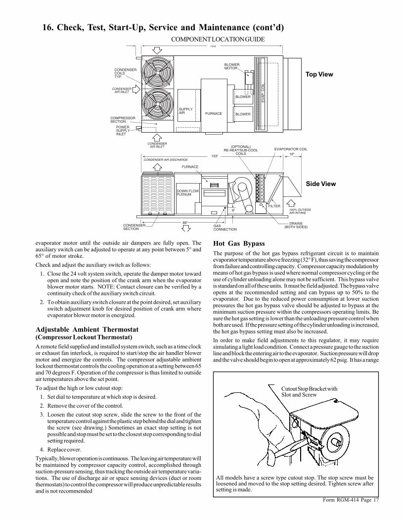
COMPONENT LOCATION GUIDE
CONDENSERSECTION
GASCONNECTION
DRAINS(BOTH SIDES)
100% OUTSIDEAIR INTAKE
FILTER
CONDENSER AIR DISCHARGE
FURNACE
(OPTIONAL)RE-HEAT/SUB-COOL
COILSEVAPORATOR COIL
DOWN FLOWPLENUM
EV
AP
. CO
IL
FURNACESUPPLYAIR
COMPRESSORSECTION
POWERSUPPLYINLET
CONDENSERCOILSTYP.
CONDENSERAIR INLET
6"
153" 19"
88"
153
BLOWER
CONDENSERAIR INLET
BLOWER
BLOWERMOTOR
Top View
Side View
evaporator motor until the outside air dampers are fully open. Theauxiliary switch can be adjusted to operate at any point between 5° and65° of motor stroke.
Check and adjust the auxiliary switch as follows:
1. Close the 24 volt system switch, operate the damper motor towardopen and note the position of the crank arm when the evaporatorblower motor starts. NOTE: Contact closure can be verified by acontinuity check of the auxiliary switch circuit.
2. To obtain auxiliary switch closure at the point desired, set auxiliaryswitch adjustment knob for desired position of crank arm whereevaporator blower motor is energized.
Adjustable Ambient Thermostat(Compressor Lockout Thermostat)
A remote field supplied and installed system switch, such as a time clockor exhaust fan interlock, is required to start/stop the air handler blowermotor and energize the controls. The compressor adjustable ambientlockout thermostat controls the cooling operation at a setting between 65and 70 degrees F. Operation of the compressor is thus limited to outsideair temperatures above the set point.
To adjust the high or low cutout stop:
1. Set dial to temperature at which stop is desired.
2. Remove the cover of the control.
3. Loosen the cutout stop screw, slide the screw to the front of thetemperature control against the plastic step behind the dial and tightenthe screw (see drawing.) Sometimes an exact stop setting is notpossible and stop must be set to the closest step corresponding to dialsetting required.
4. Replace cover.
Typically, blower operation is continuous. The leaving air temperature willbe maintained by compressor capacity control, accomplished throughsuction-pressure sensing, thus tracking the outside air temperature varia-tions. The use of discharge air or space sensing devices (duct or roomthermostats) to control the compressor will produce unpredictable resultsand is not recommended
Cutout Stop Bracket withSlot and Screw
All models have a screw type cutout stop. The stop screw must beloosened and moved to the stop setting desired. Tighten screw aftersetting is made.
Hot Gas Bypass
The purpose of the hot gas bypass refrigerant circuit is to maintainevaporator temperature above freezing (32° F), thus saving the compressorfrom failure and controlling capacity. Compressor capacity modulation bymeans of hot gas bypass is used where normal compressor cycling or theuse of cylinder unloading alone may not be sufficient. This bypass valveis standard on all of these units. It must be field adjusted. The bypass valveopens at the recommended setting and can bypass up to 50% to theevaporator. Due to the reduced power consumption at lower suctionpressures the hot gas bypass valve should be adjusted to bypass at theminimum suction pressure within the compressors operating limits. Besure the hot gas setting is lower than the unloading pressure control whenboth are used. If the pressure setting of the cylinder unloading is increased,the hot gas bypass setting must also be increased.
In order to make field adjustments to this regulator, it may requiresimulating a light load condition. Connect a pressure gauge to the suctionline and block the entering air to the evaporator. Suction pressure will dropand the valve should begin to open at approximately 62 psig. It has a range

Form RGM-414 Page 18
16. Check, Test, Start-Up, Service andMaintenance (cont’d)of 6 psig and will be fully open at 56 psig. The hot gas bypass valve willget warm to the touch when the valve begins to open. To adjust, removethe cap and turn the adjusting stem clockwise to increase the pressure andcounterclockwise to decrease the pressure. Allow 5 minutes betweenadjustment to allow the system to stabilize.
Check to be sure that suction pressure does not fall below 56 psig.Adjustments should be made in small increments, allowing the system tostabilize after each turn. Vary the evaporator load to test at variousconditions to ensure the suction pressure does not drop below the set point.Replace the seal cap on the adjusting stem.
Optional Hot Gas Reheat
Check the reheat control valve. This valve is factory set at a differential of8 to 10 psig. This should be adequate for most applications. However,if additional reheat capacity is required, increase the differential pressureto a higher value. To do this:
1. Attach discharge pressure gauges to the Schraeder connectionsupstream and downstream of the valve.
2. Remove the cap from the top of the valve and turn the stem clockwiseto increase the pressure differential and counterclockwise to decreasethe differential.
3. Verify the operation of the reheat system by turning the reheatthermostat to a temperature 5 to 10 degrees above the leaving airtemperature. The reheat solenoid will be energized and will cycle asthe temperature changes. Set the reheat thermostat at the desiredleaving air temperature.
4. Adjust the refrigerant charge by clearing the sight glass. This wouldbe the maximum charge required for this system.
5. The final adjustment of the refrigerant charge should be by subcooling.The recommended subcooling at the condensing unit should be 15degrees at 75 degrees F. and as low as 5 degrees at 105 degrees F.Verify proper operation of the thermostatic expansion valve bychecking the superheat. The superheat should be 18-20 degrees at thesuction line in the condensing section.
6. Check the airflow by checking the external static pressure. Verifythe airflow is within the ratings. Check blower motor amperage.Make adjustments as needed to ensure airflow is correct and tospecifications.
Adjustment of the reheat system should also include a calibration check ofthe head pressure control for the other fan motor(s). For more informationon the reheat control valve, see “Supplemental Instructions for Hot GasReheat.”
Cylinder Unloader Pressure Switch
Cylinder Unloading is used on all of these units with serviceable hermeticcompressors. The unloader pressure switch must be field adjusted on theseunits. It should be set to open (unload) at 64 psig and close at 78 psig.This will maintain a refrigerant temperature in the evaporator of approxi-mately 40 degrees F. This is a general recommended setting and may haveto be adjusted in up or down a few psig for optimum operation. A 14 psigdifferential should be maintained. If the compressor runs unloaded forlong periods of time, it is an indication that the control is set too high, orthat some other part of the system needs adjustment. Check airflow,expansion valve superheat, refrigerant charge or low ambient conditions.
Variable Speed Condenser Head Pressure Control
The system consists of a variable speed motor driven fan and a constantspeed motor driven fan(s). Both are controlled from refrigerant pressurerather than ambient temperature. At low ambient temperature, the variablespeed fan operates, increasing in speed as head pressure rises, untilmaximum rpm is achieved (at or around 45°F). An adjustable pressureswitch operates the constant speed three-phase fan motor(s) set to energizethe motor at 275 psig and de-energize at 220 psig. In the ambienttemperature span of approximately 50° to 53°F, the variable speed fan willramp between maximum and minimum speed while the constant speed fancycles. The start—stop cycle varies from 45 seconds to 22 minutes duringthis period. At 53°F, both fans are operating, the variable speed atminimum rpm and the constant speed at full rpm. As the ambienttemperature continues to rise, the variable speed motor increases to fullspeed and remains there.
Constant Speed 3ø Motors(s)
If the application calls for a closer setting between maximum and minimumpressure settings on the constant speed fan (for example 275 psig on, 240psig off) the effect will be to lengthen the temperature span during whichthe cycling takes place (for example 50°F to 57°F.)
The low ambient head pressure control should be factory set to cut in at 250psig and cutout at 180 psig. Check calibration of this control and if trimadjustment is required maintain as wide a differential as possible.
The recommended settings are to cutin at 280 psig and cutout at 230 psig.It is factory set to maintain a minimum head pressure of 205 psig.
Variable Speed Single Phase Motor(s)
The Electronic Fan Speed Control is used with a single phase permanentsplit capacitor motor which has been rated and approved for speed control.By directly sensing pressure, this device electronically varies the speed ofa fan motor. CAUTION: If replacement is necessary, use only single phasemotors approved by the unit manufacturer.
The throttling range of the Electronic Fan Speed Control is internally fixedand cannot be adjusted. However, the operating range can be increased ordecreased within the control’s pressure range. The operating range can beadjusted as follows:
1. Locate the adjustment screw on the control’s pressure transducer. Thescrew can be accessed through the opening in the upper left-handcorner of the control’s base
2. Turn the adjustment screw clockwise to increase or counterclock-wise to decrease the operating range. 1 turn = approximately ±35psig. CAUTION: Any adjustments should be limited to two fullturns in either direction. Over-adjustments may prohibit modula-tion of the motor and cause high head pressures.
Field repairs must not be made on this control. For a replacement controlcontact the Original Equipment Manufacturer. CAUTION: If replacementis necessary the 24 volt control circuit and the motor must be on the sameelectrical phase.

Form RGM-414 Page 19
22
GAS FURNACE CONTROLS
After gas supply pressure and regulator adjustments have been made asoutlined above, the Selectra amplifier and Maxitrol modulating regulatorvalve can be checked for proper operation and the amplifier set to theappropriate leaving air temperature setting. It is helpful to have an AC andDC voltmeter and an ohmmeter capable of reading to 15,000 ohms. It isnecessary to temporarily replace the discharge air sensor with a 4500 ohm,2 watt test resistor.
Connect a DC voltmeter to the Maxitrol modulating regulator valveterminals. Rotate the temperature selection knob (in the amplifier) tomaximum setting. The DC volts should read zero. The voltage shouldgradually increase to at least 20 volts when the temperature selector isslowly rotated to its minimum position (generally over a 3° to 4° range).
After the electronic modulation function is tested, a voltage reading mustbe taken across the automatic gas valve. This voltage reading will beapproximately 24 V AC with the temperature selection knob at maximumsetting, zero volts AC with the selector at minimum setting. The relayswitching action should occur when the modulating voltage is between 15and 19 V DC.
If these voltage readings are observed as noted, the amplifier and tempera-ture selector are operating properly. After testing, remove the resistor andreconnect the discharge air sensor.
With the modulator-regulator valve and discharge air sensor rewired asinstructed:
1. Set the selector at least 10° higher than incoming air and allowdischarge air temperature to stabilize. Discharge air temperatureshould agree with temperature selector setting.
2. Increase temperature setting by 5° to 10°. Furnace manifold pressureshould immediately go to high fire. Manifold pressure will decreaseas the discharge air temperature approaches the setting and willstabilize at the temperature setting.
3. Decrease temperature to the original setting. Burner should imme-diately turn off. Then, as the discharge air temperature decreases, theburner should ignite at low fire.
If the preceding readings are not obtained:
4. Recheck wiring to ensure system is consistent with appropriatewiring diagram.
5. Check power source for 24 volts.
6. Some automatic gas valves require as much as 20 seconds to open.In this case, check for 24 V AC output at automatic gas valve terminals.
16. Check, Test, Start-Up, Service andMaintenance (cont’d)

Form RGM-414 Page 20
CHECK, TEST AND START FORM
PRODUCT INFORMATION
GENERAL INFORMATION DATE ______________________________
START UP INFORMATIONSUPPLY VOLTAGE L1-L2 L2-L3 __________________ L1-L3 _________________________
(RETURN) ENTERING AIR TEMPERATURE _______________DB __________ WB __________ DESIGN DUCT ESP _______________
(SUPPLY) LEAVING AIR TEMPERATURE ________________DB __________ WB __________ DESIGN CFM ___________________
OUTDOOR AIR (INLET) TEMPERATURE _________________DB __________ WB __________
OUTDOOR FAN DISCHARGE AIR TEMPERATURE _______________ DB ________
SUCTION PRESSURE ___________PSIG SUCTION LINE TEMP _____________DEGREES SUPERHEAT ___________ DEGREES
NOTE: TO CALCULATE SUPERHEAT, CONVERT SUCTION PRESSURE TO SATURATION TEMPERATURE, THEN SUBTRACT THE SUCTION LINE TEMPERATURE FROM
THE SATURATION TEMPERATURE OF THE EVAPORATOR.
DISCHARGE PRESSURE _________PSIG LIQUID LINE HEAD PRESSURE __________ PSIG
LIQUID LINE TEMPERATURE ______________ DEGREES SUBCOOLING ____________ DEGREES
NOTE: TO CALCULATE SUBCOOLING CONVERT HEAD PRESSURE TO SATURATION TEMPERATURE, THEN SUBTRACT THE LIQUID LINE TEMPERATURE FROM THE
CONDENSING TEMPERATURE (SATURATION).
OIL LEVEL ____________ CRANKCASE HEATER OPERATING _________________SIGHT GLASS CLEAR ______________
NOISE LEVEL _______________ CONDITION OF UNIT _______________________________________________________________
COMPRESSOR(S)
#1 FLA ______ VOLTAGE T1-T2 ________ T2-T3 _______ T1-T3 _______ AMPERAGE 1PH __________ 2PH ______ 3PH _____
#2 FLA ______ VOLTAGE T1-T2 ________ T2-T3 _______ T1-T3 _______ AMPERAGE 1PH __________ 2PH ______ 3PH _____
CONDENSER FAN(S) HP _____________FLA _____________ BLOWER MOTOR HP _______________ FLA ___________
#1 VOLTAGE __________________ AMPERAGE _________________ #3 VOLTAGE __________________ AMPERAGE ______________
#2 VOLTAGE __________________ AMPERAGE _________________ #4 VOLTAGE __________________ AMPERAGE ______________
High Pressure Switch
Low Pressure Switch
Pumpdown Low Pressure
Low Ambient Fan #1
Low Ambient Fan #2
Low Ambient Fan #3
Low Ambient Fan #4
Oil Failure Control
Hot Gas Bypass
Cylinder Unloader Switch
UNIT MODEL # ____________________________________ UNIT SERIAL # _________________________________
A/H NON-COND. SPACE _______________________ DUCTWORK-ESTIMATE TOTAL EQUIVALENT FEET ______________________________
LIQUID LINE SOLENOID INSTALLED ______________________________ HOT GAS BYPASS INSTALLED ______________________________
CYLINDER UNLOADING _________________________ TYPE OF HEAD PRESSURE CONTROL USED __________________________________
HOT GAS REHEAT ________________ PHASE MONITOR PROTECTION ____________________ TYPE OF THERMOSTAT _________________
ELECTRIC HEAT INSTALLED ____________________ LIQUID INJECTION ____________________ OTHER OPTIONAL ___________________
CUSTOMER NAME __________________________________ DEALER NAME _________________________________ADDRESS ________________________________________ ADDRESS _____________________________________CITY ____________________________________________ CITY ________________________________________ST, ZIP _________________________________________ ST, ZIP ______________________________________PHONE # _________________________________________ PHONE # ______________________________________
SETTINGS CUT-IN CUT-OUT CUT-IN CUT-OUT

Form RGM-414 Page 21
16G
. T
rou
ble
Sh
ooti
ng G
uid
esG
en
era
l R
efr
igera
tio
n
Cir
cu
it
SY
MP
TO
MP
OS
SIB
LE
CA
US
ER
EM
ED
Y
A.
Co
mp
ress
or
wil
l n
ot
start
1.
Po
wer
off
, lo
ose
ele
ctr
ical
co
nn
ecti
on
s o
r fu
se o
pen
.1
.C
heck
dis
co
nn
ect
swit
ch
, fu
ses
an
d w
irin
g.
Rep
lace p
art
s o
r re
pair
as
necess
ary
.
2.
Co
mp
ress
or
co
nta
cto
r n
ot
clo
sin
g.
2.
Ch
eck
vo
ltag
e t
o c
on
tacto
r co
il,
tran
sfo
rmer,
sla
ve r
ela
y, s
yst
em
. R
ep
lace p
art
s as
necess
ary
.
3.
Inte
rnal
co
mp
ress
or
therm
al
ov
erl
oad
op
en
.3
.If
co
mp
ress
or
is h
ot,
all
ow
2 h
ou
rs t
o c
oo
l. S
ee t
herm
al
ov
erl
oad
belo
w.
4.
Co
mp
ress
or
defe
cti
ve.
4.
Ch
eck
co
mp
ress
or
for
ele
ctr
ical
fail
ure
. C
om
pre
sso
r m
ay
be s
eiz
ed
, ch
eck
fo
r L
.R.A
.
5.
Hig
h o
r lo
w p
ress
ure
sw
itch
op
en
or
defe
cti
ve.
5.
Ch
eck
cali
bra
tio
n o
f h
igh
or
low
pre
ssu
re s
wit
ch
, re
-cali
bra
te o
r re
pla
ce.
6.
Oil
pre
ssu
re c
on
tro
l o
pen
or
defe
cti
ve.
6.
Ch
eck
oil
fail
ure
co
ntr
ol.
See o
il f
ail
ure
co
ntr
ol
belo
w.
B.
Co
mp
ress
or
start
s b
ut
cu
ts1
.L
ow
refr
igera
nt
ch
arg
e1
.C
heck
sig
htg
lass
an
d c
heck
pre
ssu
res.
ou
t o
n l
ow
pre
ssu
re s
wit
ch
.2
.A
irfl
ow
rest
ricte
d.
2.
Ch
eck
fo
r d
irty
ev
ap
ora
tor
co
il,
dir
ty f
ilte
rs,
dam
pers
clo
sed
, ic
ed
ev
ap
ora
tor,
imp
rop
er
belt
, ch
eck
mo
tor
am
ps,
du
ct
desi
gn
.
3.
Rest
ricti
on
in
liq
uid
lin
e.
3.
Ch
eck
head
pre
ssu
re,
ch
eck
an
d a
dju
st T
XV
if
no
t fu
ncti
on
ing
pro
perl
y,
ch
eck
pre
ssu
re d
rop
acro
ss f
ilte
r d
rier.
4.
Defe
cti
ve l
ow
pre
ssu
re s
wit
ch
.4
.C
heck
cali
bra
tio
n o
f sw
itch
.
C.
Co
mp
ress
or
start
s b
ut
cu
ts1
.R
efr
igera
nt
ov
erc
harg
e.
1.
Ch
eck
pre
ssu
res,
ch
arg
e b
y s
ub
co
oli
ng
.
ou
t o
n h
igh
pre
ssu
re s
wit
ch
.2
.C
on
den
ser
fan
co
ntr
ol
has
inco
rrect
sett
ing
.2
.C
heck
cali
bra
tio
n o
f lo
w a
mb
ien
t co
ntr
ol.
3.
Fan
mo
tor
defe
cti
ve.
3.
Ch
eck
fan
mo
tor.
4.
Co
nd
en
ser
co
il i
nle
t o
bst
ructe
d o
r d
irty
.4
.C
heck
co
il a
nd
in
let
cle
ara
nces
an
d f
or
po
ssib
le a
ir r
ecir
cu
lati
on
.
5.
Air
or
no
n-c
on
den
sab
les
in s
yst
em
.5
.C
heck
hig
h s
ide e
qu
ali
zed
pre
ssu
re r
ead
ing
wit
h e
qu
ivale
nt
ou
tdo
or
tem
pera
ture
.
6.
Defe
cti
ve h
igh
pre
ssu
re s
wit
ch
.6
.C
heck
cali
bra
tio
n o
f sw
itch
.
7.
Rest
ricti
on
in
dis
ch
arg
e o
r li
qu
id l
ine.
7.
Ch
eck
dis
ch
arg
e a
nd
liq
uid
lin
e p
ress
ure
s, c
heck
TX
V.
D.
Com
pre
ssor
cuts
out
on
1.
Lo
w
vo
ltag
e.
1.
C
hec
k v
olt
age.
th
erm
al
ov
erlo
ad.
2.
Su
stai
ned
h
igh
d
isch
arg
e p
ress
ure
.2
.C
hec
k ru
nnin
g a
mper
age
and c
ondit
ions des
crib
ed u
nder
“hig
h d
isch
arge
pre
ssure
.”
3.
Hig
h
suct
ion
an
d
dis
char
ge
pre
ssu
res.
3.
Ch
eck
TX
V s
etti
ng
, ch
eck
fo
r ai
r in
sy
stem
.
4.
Defe
cti
ve
co
mp
ress
or
ov
erl
oad
.4
.A
llow
co
mpre
ssor
to co
ol
for
two hours
if
co
mpre
ssor
is hot.
R
echec
k fo
r open
ci
rcuit
.
5.
Def
ecti
ve
run
ca
pac
ito
r.5
.C
hec
k ru
n ca
pac
ito
r fo
r co
mp
ress
or
and
fa
n m
oto
r.
6.
Imp
rop
er
refr
igera
nt
ch
arg
e.
6.
Ch
eck
su
bco
oli
ng
.
7.
Bea
rings
or
pis
tons
too ti
ght.
7.
Chec
k f
or
low
oil
lev
el.
8.
All
ow
ti
me
for
com
pre
sso
r to
co
ol.
8.
Ch
eck
d
om
e te
mp
erat
ure
o
f th
e co
mp
ress
or.
E.
Com
pre
ssor
cuts
out
on oil
1.
Low
oil
le
vel
.1
.C
hec
k c
rankca
se s
ightg
lass
- a
dd o
il t
o b
ring l
evel
to m
idw
ay i
n s
ightg
lass
.
fa
ilu
re
con
tro
l (s
emi-
her
m.)
2.
Def
ecti
ve
oil
p
um
p.
2.
Ch
eck
o
il
pu
mp
.
3.
Defe
cti
ve
co
ntr
ol.
3.
Ch
eck
o
il fa
ilu
re co
ntr
ol
for
cali
bra
tio
n.
4.
Liq
uid
re
frig
eran
t is
en
teri
ng
cr
ank
case
.4
.C
om
pre
sso
r w
ill
be
wet
. C
hec
k cr
ank
case
h
eate
r o
r ca
use
fo
r li
qu
id fe
edb
ack
.
F.
No
isy
co
mp
ress
or.
1.
Scr
oll
co
mp
ress
ors
ar
e ro
tati
on
se
nsi
tiv
e.1
.R
ever
se w
irin
g at
d
isco
nn
ect
swit
ch,
rech
eck
fo
r co
rrec
t ev
apo
rato
r b
low
er ro
tati
on
.
2.
Refr
igera
nt
ov
erc
harg
e.
2.
Ch
eck
p
ress
ure
s an
d
sub
coo
lin
g.
3.
Exce
ssiv
e or
insu
ffic
ient
oil
in
co
mpre
ssor
3.
Chec
k oil
le
vel
in
her
met
ic co
mpre
ssors
. C
hec
k to
tal
equiv
alen
t fe
et of
pip
ing.
Add
cra
nk
case
.o
il
as
reco
mm
end
ed.
4.
Liq
uid
fl
oo
db
ack
.4
.C
hec
k
TX
V
sett
ing
. C
hec
k
for
refr
iger
ant
ov
erch
arg
e.
5.
Tu
bin
g
ratt
le.
5.
Dam
pen
tu
bin
g v
ibra
tio
n b
y ta
pin
g o
r cl
amp
ing
. B
end
tu
bin
g aw
ay fr
om
co
nta
ct w
her
e
po
ssib
le.
6.
Co
mp
ress
or
defe
cti
ve.
6.
Ch
eck
in
tern
al
par
ts
(sem
i-h
erm
.)

Form RGM-414 Page 22
Gen
eral
Ref
riger
ati
on
C
ircu
it (c
on
tin
ued
)
SY
MP
TO
MP
OS
SIB
LE
CA
US
ER
EM
ED
Y
G.
No
isy
un
it o
pera
tio
n.
1.
Blo
wer
rota
tio
nal
no
ise.
1.
Ch
eck
blo
wer,
mo
tor
an
d d
riv
e f
or
fau
lty
ad
just
men
t o
r n
ois
y b
eari
ng
s, l
oo
se p
art
s,
blo
wer
ou
t o
f b
ala
nce.
2.
Air
no
ise.
2.
Ch
eck
du
ctw
ork
. A
ir v
elo
cit
y t
oo
hig
h.
3.
Ch
att
eri
ng
co
nta
cto
r.3
.C
heck
fo
r ad
eq
uate
co
ntr
ol
vo
ltag
e,
ch
eck
fo
r sh
ort
s o
r b
reak
s, c
heck
th
erm
ost
at,
ch
eck
co
nta
ct
po
ints
.
4.
Tu
bin
g r
att
le.
4.
Dam
pen
by
tap
ing
or
cla
mp
ing
, b
en
d t
ub
ing
aw
ay
fro
m c
on
tact
wh
en
po
ssib
le.
H.
Hig
h s
ucti
on
pre
ssu
re.
1.
Ex
cess
ive l
oad
on
ev
ap
ora
tor
co
il.
1.
Ch
eck
fo
r h
igh
en
teri
ng
wet
bu
lb t
em
pera
ture
. C
heck
fo
r ex
cess
ive
air
flo
w.
2.
Bro
ken
co
mp
ress
or
valv
es.
Scro
ll c
om
pre
sso
rs2
.R
em
ov
e h
ead
(se
mi-
herm
.) i
nsp
ect
valv
es
reed
s. S
cro
ll c
om
pre
sso
rs s
ho
uld
no
t b
e
do
no
t h
av
e v
alv
es.
pu
mp
ed
do
wn
belo
w 5
psi
g.
re-c
ali
bra
te u
nlo
ad
er
pre
ssu
re s
wit
ch
.
3.
Co
mp
ress
or
is u
nlo
ad
ed
.3
.C
heck
head
pre
ssu
re,
ch
eck
an
d a
dju
st T
XV
if
no
t fu
ncti
on
ing
pro
perl
y,
ch
eck
pre
ssu
re d
rop
acro
ss f
ilte
r d
rier.
4.
Leak
ing
ch
eck
valv
e.
4.
Ch
eck
tem
pera
ture
acro
ss c
heck
valv
e.
5.
Ex
pan
sio
n v
alv
e n
ot
secu
red
to
su
cti
on
lin
e o
r5
.C
heck
th
e T
XV
, en
sure
bu
lb i
s in
sula
ted
.
TX
V d
efe
cti
ve.
I.H
igh
dis
ch
arg
e p
ress
ure
.1
.T
XV
sett
ing
.1
.C
heck
TX
V s
ett
ing
an
d c
ali
bra
te s
up
erh
eat.
2.
Air
in
let
to c
on
den
ser
dir
ty o
r o
bst
ructe
d.
2.
Ch
eck
fo
r p
rop
er
cle
ara
nces
an
d p
oss
ible
air
recir
cu
lati
ng
.
3.
Co
nd
en
ser
fan
mo
tor
defe
cti
ve.
3.
Ch
eck
co
nd
en
ser
fan
mo
tor
an
d r
un
cap
acit
or.
4.
Co
nd
en
ser
fan
co
ntr
ol
has
inco
rrect
sett
ing
.4
.C
heck
cali
bra
tio
n o
f lo
w a
mb
ien
t h
ead
pre
ssu
re c
on
tro
l.
J.S
ucti
on
pre
ssu
re t
oo
lo
w.
1.
Refr
igera
nt
un
derc
harg
e.
1.
Ch
eck
pre
ssu
res
an
d s
ub
co
oli
ng
.
2.
Blo
wer
run
nin
g
back
ward
.2
.In
terc
han
ge
any tw
o w
ires
fr
om
3 phas
e dis
connec
t.
3.
Lo
ose
b
low
er,
pu
lley
o
r b
elts
.3
.C
hec
k
dri
ve
pu
lley
al
ign
men
t,
bel
t te
nsi
on
.
4.
Def
ecti
ve
or
imp
rop
erly
ad
just
ed
exp
ansi
on
v
alv
e.4
.C
hec
k su
per
hea
t an
d ad
just
T
XV
.
5.
Dir
ty
filt
er.
5.
Ch
eck
fi
lter
an
d
evap
ora
tor
coil
.
6.
Too li
ttle
ai
r fl
ow
or
low
en
teri
ng ai
r te
mper
ature
.6
Chec
k ai
rflo
w an
d en
teri
ng ai
r w
et bulb
co
ndit
ions.
7.
Res
tric
tio
n in
su
ctio
n o
r li
qu
id li
ne.
7.
Ch
eck
re
frig
eran
t ci
rcu
it
for
rest
rict
ion
K.
Hea
d pre
ssure
to
o lo
w.
1.
Insu
ffic
ien
t re
frig
era
nt
ch
arg
e.
1.
Ch
eck
su
bco
oli
ng
, ch
eck
fo
r le
ak.
2.
Def
ecti
ve
or
imp
rop
erly
ad
just
ed
exp
ansi
on
v
alv
e.2
.C
hec
k
sup
erh
eati
ng
an
d
adju
st
TX
V.
3.
Lo
w
suct
ion
p
ress
ure
.3
.S
ee “s
uct
ion
p
ress
ure
to
o lo
w”
abo
ve.
4.
Co
nd
ense
r fa
n
con
tro
l se
ttin
g.
4.
Ch
eck
ca
lib
rati
on
o
f lo
w
amb
ien
t co
ntr
ol.
5.
Defe
cti
ve
co
mp
ress
or.
5.
See
“h
igh
su
ctio
n
pre
ssu
re”
abo
ve.
L.
Co
mp
ress
or
sho
rt
cycl
es.
1.
Th
erm
ost
at
loca
tio
n
or
mal
fun
ctio
n.
1.
Ch
eck
th
erm
ost
at,
chec
k
hea
t an
tici
pat
or
sett
ing
.
2.
Imp
rop
er
refr
igera
nt
ch
arg
e.
2.
Ch
eck
su
bco
oli
ng
, v
eri
fy
sup
erh
eat.
3.
Def
ecti
ve
hig
h or
low
pre
ssure
co
ntr
ol.
3.
Chec
k hig
h or
low
pre
ssure
sw
itch
.
4.
Liq
uid
fl
oo
db
ack
.4
.P
oss
ible
ti
ght
bea
rings,
se
e ab
ove.
5.
Defe
cti
ve
ex
pan
sio
n
valv
e.
5.
Ch
eck
T
XV
an
d
sup
erh
eat.
6.
Po
or
air
d
istr
ibu
tio
n.
6.
Ch
eck
d
uctw
ork
fo
r re
cir
cu
lati
ng
.
7.
Hig
h
dis
char
ge
pre
ssu
re.
7.
See
“h
igh
d
isch
arg
e p
ress
ure
” ab
ov
e.
8.
Lea
kin
g
dis
char
ge
val
ves
in
co
mp
ress
or.
8.
See
“h
igh
su
ctio
n
pre
ssu
re”
abo
ve.
M.
Runnin
g cy
cle
too lo
ng or
1.
Refr
igera
tio
n
un
derc
harg
ed
.1
.C
heck
su
bco
oli
ng
.
un
it
op
era
tes
co
nti
nu
ou
sly
.2
.D
irty
fi
lter
or
evap
ora
tor
coil
.2
.C
hec
k fi
lter
, co
il an
d ai
rflo
w.
3.
Dir
ty
or
clo
gg
ed
con
den
ser
coil
.3
.C
hec
k co
il an
d ai
rflo
w.
4.
Air
o
r o
ther
n
on
-co
nd
ensa
ble
s in
sy
stem
.4
.C
hec
k
equ
aliz
ed
hig
h
sid
e p
ress
ure
w
ith
eq
uiv
alen
t o
utd
oo
r te
mp
erat
ure
.
5.
Defe
cti
ve
co
mp
ress
or.
5.
See
“h
igh
su
ctio
n
pre
ssu
re”
abo
ve.
6.
Res
tric
tion in
su
ctio
n an
d li
quid
li
ne.
6.
Chec
k fo
r re
stri
ctio
ns
in re
frig
eran
t ci
rcuit
.
7.
Co
ntr
ol
con
tact
s st
uck
.7
.C
hec
k th
erm
ost
at,
sho
rts
in w
irin
g,
slav
e re
lay
co
mp
ress
or
con
tact
or

Form RGM-414 Page 23
Va
ria
ble
Sp
eed
Co
nd
ense
r H
ead
Pre
ssu
re C
on
tro
l
SY
MP
TO
MP
OS
SIB
LE
CA
US
ER
EM
ED
Y
A.
No
fan
op
era
tio
n.
1.
Inp
ut
pre
ssu
re i
s b
elo
w o
pera
tin
g r
an
ge.
1.
No
pro
ble
m,
no
rmal
op
era
tio
n.
2.
No
24
vo
lt c
on
tro
l v
olt
ag
e2
.C
hec
k f
or
24 V
AC
at
contr
ol.
3.
No
in
pu
t p
ress
ure
to
co
ntr
ol.
3.
Ch
eck
ali
gn
men
t o
f C
ap
illa
ry f
itti
ng
. S
ch
rad
er
valv
e d
ep
ress
or
mu
st d
ep
ress
Sch
rad
er
valv
e e
no
ug
h t
o a
llo
w p
ress
ure
in
to c
ap
illa
ry.
4.
Bad
fan
mo
tor.
4.
Dis
co
nn
ect
po
wer.
Pla
ce a
ju
mp
er
fro
m L
1 t
o M
1 a
nd
co
nn
ect
po
wer.
If
fan
do
es
no
t
start
, m
oto
r is
bad
an
d s
ho
uld
be r
ep
laced
.
5.
Pre
ssu
re t
ran
sdu
cer
pro
ble
m.
5.
Dis
co
nn
ect
6 p
in c
on
necto
r fr
om
rig
ht
sid
e o
f co
ntr
ol.
Pla
ce a
ju
mp
er
wir
e b
etw
een
thir
d p
in f
rom
th
e t
op
an
d b
ott
om
pin
on
th
e c
on
tro
l (n
ot
the c
ab
le).
If
fan
go
es
to f
ull
speed
, ch
eck
fo
r in
pu
t p
ress
ure
. If
it
has
been
dete
rmin
ed
th
ere
is
ad
eq
uate
pre
ssu
re,
the t
ran
sdu
cer
is b
ad
an
d t
he c
on
tro
l m
ust
be r
ep
laced
.
B.
Fan
sto
ps
wh
en
pre
ssu
re1
.C
on
tro
l is
no
t w
ired
co
rrectl
y.
1.
See w
irin
g d
iag
ram
s.
reach
es
the h
igh
en
d o
f
the o
pera
tin
g r
an
ge.
C.
No
fan
mo
du
lati
on
1.
Co
ntr
ol
is n
ot
wir
ed
co
rrectl
y.
1.
See w
irin
g d
iag
ram
s.
(On
-Off
Op
era
tio
n)
D.
Fan
sta
rts
at f
ull
sp
eed
.1
.C
on
tro
l is
no
t w
ired
co
rrec
tly.
1.
See
wir
ing
dia
gra
ms.
E.
Err
ati
c
fan
o
pera
tio
n.
1.
Contr
ol
is not
wir
ed co
rrec
tly.
1.
Chec
k t
o s
ee i
f co
ntr
ol
volt
age
(24 V
AC
) is
on s
ame
phas
e as
moto
r.
2.
Dir
ty
or
blo
cked
co
nd
ense
r co
il.
2.
Cle
an
con
den
ser
coil
.
F.
Fan
moto
r is
cycl
ing o
n1
.D
irty
or
blo
cked
co
nden
ser
coil
.1.
Cle
an c
onden
ser
coil
.
therm
al
ov
erl
oad
.2
.W
ron
g
mo
tor
for
fan
sp
eed
co
ntr
ol
app
lica
tio
n.
2.
Rep
lace
w
ith
m
oto
r ap
pro
ved
fo
r fa
n
spee
d
con
tro
l ap
pli
cati
on
.
Gen
eral
Ref
riger
ati
on
C
ircu
it (c
on
tin
ued
)
SY
MP
TO
MP
OS
SIB
LE
CA
US
ER
EM
ED
Y
N.
Su
pp
ly a
ir t
em
pera
ture
1.
Refr
igera
nt
un
derc
harg
e o
r le
ak
in
sy
stem
.1
.C
heck
su
bco
oli
ng
an
d c
heck
fo
r le
ak
s.
too
hig
h.
2.
Ev
ap
ora
tor
plu
gg
ed
wit
h d
irt
or
ice.
2.
Ch
eck
ev
ap
ora
tor,
air
flo
w a
nd
fil
ter.
3.
Imp
rop
erl
y a
dju
sted
or
defe
cti
ve e
xp
an
sio
n v
alv
e.
3.
Ch
eck
su
perh
eat
an
d a
dju
st T
XV
, ch
eck
bu
lb.
4.
Defe
cti
ve c
om
pre
sso
r.4
.C
heck
co
mp
ress
or
for
pro
per
op
era
tio
n.
5.
Hig
h d
isch
arg
e p
ress
ure
.5
.S
ee “
hig
h d
isch
arg
e p
ress
ure
” a
bo
ve.
6.
Air
flo
w i
s to
o h
igh
.6
.C
heck
ex
tern
al
stati
c p
ress
ure
.
O.
Su
pp
ly a
ir t
em
pera
ture
1.
Air
flo
w i
s to
o l
ow
.1
.C
heck
ev
ap
ora
tor
co
il,
filt
er,
ch
eck
fo
r clo
sed
dam
pers
, g
rill
s, d
riv
e f
or
loo
se p
art
s,
too
lo
w.
belt
s,
mis
ali
gn
men
t, c
heck
ex
tern
al
stati
c p
ress
ure
.
2.
Retu
rn a
ir t
em
pera
ture
to
o l
ow
.2
.C
heck
en
teri
ng
air
wet
bu
lb c
on
dit
ion
s.
P.
Liq
uid
lin
e t
oo
ho
t.1
.R
efr
igera
nt
un
derc
harg
e.
1.
Ad
just
th
e c
harg
e b
y s
ub
co
oli
ng
.
2.
Hig
h d
isch
arg
e p
ress
ure
.2
.S
ee “
hig
h d
isch
arg
e p
ress
ure
” a
bo
ve.
Q.
Liq
uid
lin
e f
rost
ed
or
wet.
1.
Rest
ricti
on
in
liq
uid
lin
e.
1.
Rest
ricti
on
up
stre
am
of
po
int
of
fro
stin
g.
R.
Su
cti
on
lin
e f
rost
ing
.1
.In
suff
icie
nt
ev
ap
ora
tor
air
flo
w.
1.
Ch
eck
air
flo
w,
ch
eck
dri
ve f
or
loo
se p
art
s, b
elt
s, c
lose
d d
am
pers
.
2.
Res
tric
tion in
su
ctio
n or
liquid
li
ne.
2.
Res
tric
tion upst
ream
of
poin
t of
frost
ing.
3.
Malf
un
cti
on
ing
o
r d
efe
cti
ve
ex
pan
sio
n
valv
e.
3.
Chec
k bulb
of
TX
V.
S.
Blo
wer
m
oto
r n
ot
run
nin
g.
1.
Imp
rop
er
wir
ing
.1.
C
hec
k w
irin
g dia
gra
ms.
2.
Defe
cti
ve
mo
tor.
2.
Ch
eck
m
oto
r an
d
co
ntr
oll
er.
3.
Def
ecti
ve
ther
mo
stat
o
r co
ntr
ol
circ
uit
.3
.C
hec
k
con
tro
l ci
rcu
it.
4.
Mo
tor
off
o
n
ov
erlo
ad
pro
tect
or.
4.
All
ow
m
oto
r to
co
ol,
ch
eck
am
per
age.

Form RGM-414 Page 24
Ho
t G
as
By
pa
ss R
egu
lato
r
SY
MP
TO
MP
OS
SIB
LE
CA
US
ER
EM
ED
Y
A.
Err
ati
c p
ress
ure
co
ntr
ol.
1.
Defe
cti
ve r
eg
ula
tor.
1.
Rep
lace d
efe
cti
ve p
art
.
2.
Dir
t cau
sin
g r
eg
ula
tor
to b
ind
.2
.D
isass
em
ble
reg
ula
tor
an
d c
lean
in
tern
al
part
s. I
nst
all
AL
CO
str
ain
er.
3.
Po
wer
sou
rce t
o h
ot
gas
sole
no
id o
r o
pera
tio
n o
f3
.D
ete
rmin
e i
f p
rob
lem
is
cau
sed
by
su
pp
ly v
olt
ag
e,
sole
no
id,
or
ex
cess
ive M
OP
D.
the s
ole
no
id i
s in
term
itte
nt.
Mak
e c
han
ges
necess
ary
to
co
rrect
pro
ble
m.
B.
Reg
ula
tor
leak
ag
e.
1.
Dir
t in
reg
ula
tor
cau
sin
g s
eat
to r
emai
n o
pen
.1
.C
lean
th
e re
gu
lato
r. I
nst
all
AL
CO
str
ain
er.
2.
Wo
rn o
r ero
ded
seati
ng
su
rface o
n r
eg
ula
tor.
2.
Rep
lace d
efe
cti
ve p
art
.
C.
Reg
ula
tor
hu
nti
ng
1.
Reg
ula
tor
is o
vers
ized
.1
.C
on
tact
OE
M m
an
ufa
ctu
rer
for
co
rrectl
y s
ized
reg
ula
tor.
(ch
att
eri
ng
) w
ild
2.
Reg
ula
tor
an
d E
PR
hav
e c
on
tro
l in
tera
cti
on
.2
.M
ov
e t
he e
xte
rnal
eq
uali
zer
lin
e d
ow
nst
ream
fro
m t
he E
PR
.
flu
ctu
ati
on
s in
3.
Reg
ula
tor
an
d l
iqu
id i
nje
cti
on
Th
erm
o V
alv
e3
.In
cre
ase
su
perh
eat
sett
ing
. D
am
pen
bu
lb r
esp
on
se b
y r
ep
osi
tio
nin
g.
co
ntr
oll
ed
pre
ssu
res.
hav
e c
on
tro
l in
tera
cti
on
.
4.
Reg
ula
tor
an
d c
yli
nd
er
un
load
ers
hav
e4
.D
iffe
ren
tial
sho
uld
be i
ncre
ase
d b
etw
een
th
e c
on
tro
ls b
y l
ow
eri
ng
th
e r
eg
ula
tor’
s
co
ntr
ol
inte
racti
on
.se
t p
oin
t.
D.
Reg
ula
tor
wil
l n
ot
pro
vid
e1
.R
eg
ula
tor
seat
is r
est
ricte
d.
1.
Lo
cate
an
d r
em
ov
e s
top
pag
e.
Inst
all
AL
CO
str
ain
er.
pre
ssu
re c
on
tro
l.2
.P
ress
ure
ad
just
ing
ste
m i
s se
t at
a p
oin
t so
hig
h2
.R
ead
just
th
e r
eg
ula
tor.
that
su
ctio
n pre
ssure
nev
er re
aches
th
e se
t poin
t.
3.
Exte
rnal
eq
ual
izer
li
ne
upst
ream
of
the
EP
R.
3.
Move
exte
rnal
eq
ual
izer
li
ne
dow
nst
ream
fr
om
th
e E
PR
.
4.
Str
ainer
cl
ogged
at
th
e re
gula
tor
inle
t.4
.L
oca
te
and
re
mo
ve
sto
pp
age.
5.
MO
PD
ex
ceed
ed ac
ross
th
e so
len
oid
o
r lo
ss5
.R
epla
ce
sole
no
id
or
tro
ub
le—
sho
ot
the
elec
tric
al
pro
ble
m.
of
sou
rce
vo
ltag
e.
6.
So
len
oid
co
il
bu
rn
ou
t.6
.R
epla
ce
coil
.
7.
Wro
ng ty
pe
dis
trib
uto
r fo
r hot
gas
bypas
s to
7.
Inst
all
pro
per
V
entu
ri -
Flo
ty
pe
dis
trib
uto
r fo
r lo
w pre
ssure
dro
p.
the
ev
ap
ora
tor.
E.
Reg
ula
tor
fail
s to
clo
se.
1.
Dir
t u
nd
er
seat
of
the r
eg
ula
tor.
1.
Lo
cate
an
d r
em
ov
e s
top
pag
e.
Inst
all
AL
CO
str
ain
er
or
EK
dri
er
filt
er.
2.
Dia
ph
rag
m
fail
ure
(l
eak
age
aro
un
d
the
2.
Rep
lace
d
efec
tiv
e p
arts
.
ad
just
ing
st
em
)
3.
Pre
ssu
re a
dju
stin
g s
tem
is
set
at a
po
int
so h
igh
3.
Rea
dju
st
the
reg
ula
tor.
that
su
ctio
n nev
er re
aches
th
e se
t poin
t.
4.
Blo
cked
ex
tern
al eq
ual
izer
pas
sage.
4.
Loca
te an
d re
move
stoppag
e. In
stal
l A
LC
O st
rain
er.
5.
Wo
rn o
r er
od
ed re
gu
lato
r se
at.
5.
Rep
lace
d
efec
tiv
e p
art.

Form RGM-414 Page 25
Gen
era
l G
as
Fu
rna
ce
SY
MP
TO
MP
OS
SIB
LE
CA
US
ER
EM
ED
Y
A.
Ven
ter
mo
tor
wil
l n
ot
start
.1
.M
an
ual
valv
e n
ot
op
en
.1
.T
urn
on
po
wer.
Ch
eck
su
pp
ly f
use
s o
r cir
cu
it b
reak
er.
2.
No
24
vo
lt p
ow
er
to v
en
ter
rela
y.
2.
Tu
rn u
p t
herm
ost
at,
ch
eck
co
ntr
ol
tran
sfo
rmer
ou
tpu
t. C
heck
fo
r lo
ose
or
imp
rop
er
wir
e c
on
necti
on
s.
3.
Ven
ter
rela
y d
efe
cti
ve
3.
Rep
lace.
4.
Defe
cti
ve m
oto
r o
r cap
acit
or.
4.
Rep
lace d
efe
cti
ve p
art
.
B.
Pil
ot
wil
l n
ot
lig
ht.
1.
Man
ual
valv
e n
ot
op
en
.1
.O
pen
man
ual
valv
e.
2.
Air
in
gas
lin
e.2
.B
leed
gas
lin
e.
3.
Dir
t in
pil
ot
ori
fice.
3.
Rem
ov
e a
nd
cle
an
wit
h c
om
pre
ssed
air
or
solv
en
t (d
o n
ot
ream
).
4.
Gas
pre
ssu
re t
oo
hig
h o
r to
o l
ow
.4
.A
dju
st s
up
ply
pre
ssu
re
5.
Kin
ked
pil
ot
tub
ing
.5
.R
ep
lace t
ub
ing
.
6.
Pil
ot
valv
e d
oes
no
t o
pen
.6
.If
24
vo
lt a
vail
ab
le a
t v
alv
e,
rep
lace v
alv
e.
7.
No
sp
ark
.7
.
a)
Lo
ose
wir
e c
on
necti
on
s.a
)B
e ce
rtai
n a
ll w
ires
co
nn
ecti
on
s ar
e so
lid
.
b)
Tra
nsf
orm
er
fail
ure
.b
)B
e ce
rtai
n 2
4 v
olt
s ar
e av
aila
ble
.
c)
Inco
rrect
spark
g
ap
.c
)M
ainta
in sp
ark gap
at
7/6
4”.
d)
Sp
ark
ca
ble
sh
ort
ed
to
gro
un
d.
d)
Rep
lace
w
orn
o
r g
rou
nd
ed
spar
k
cab
le.
e)
Sp
ark
el
ectr
od
e sh
ort
ed
to
gro
un
d.
e)
Rep
lace
p
ilo
t if
ce
ram
ic sp
ark
el
ectr
od
e is
cr
ack
ed o
r g
rou
nd
ed.
f)D
raft
s af
fect
ing
pil
ot.
f)M
ake
sure
all
pan
els
are
in p
lace
and t
ightl
y s
ecure
d t
o p
reven
t dra
fts
at p
ilot.
g)
Ign
itio
n
co
ntr
ol
no
t g
rou
nd
ed
.g
)M
ake
cert
ain ig
nit
ion co
ntr
ol
is gro
unded
to
fu
rnac
e ch
assi
s.
h)
Fau
lty
ig
nit
ion
co
ntr
oll
er.
h)
If 2
4 v
olt
is
avai
lable
to i
gnit
ion c
ontr
oll
er a
nd a
ll o
ther
cau
ses
hav
e bee
n
eli
min
ate
d,
rep
lace
ign
itio
n
co
ntr
ol.
8.
Op
tio
nal
lo
cko
ut
dev
ice
inte
rru
pti
ng
co
ntr
ol
8)
Res
et
lock
ou
t b
y
inte
rru
pti
ng
co
ntr
ol
po
wer
.
circ
uit
by ab
ove
cause
s.
9.
Fau
lty
co
mb
ust
ion
ai
r p
rov
ing
sw
itch
.9
)R
epla
ce
com
bu
stio
n
air
pro
vin
g
swit
ch.
C.
Pil
ot
lig
hts
, m
ain
val
ve
1.
Man
ual
v
alv
e n
ot
op
en.
1.
Op
en
man
ual
v
alv
e.
wil
l n
ot
op
en
.2
.M
ain
valv
e n
ot
op
en
ing
.2
.
a)
Defe
cti
ve v
alv
e.
a)
If 2
4 v
olt
is
measu
red
at
valv
e c
on
necti
on
s an
d v
alv
e r
em
ain
s clo
sed
,
rep
lace v
alv
e.
b)
Lo
ose
wir
e c
on
necti
on
s.b
)C
heck
an
d t
igh
ten
all
wir
ing
co
nn
ecti
on
s.
3.
Ign
itio
n c
on
tro
l d
oes
no
t p
ow
er
main
valv
e.
3.
a)
Lo
ose
wir
e c
on
necti
on
s.a
)C
heck
an
d t
igh
ten
all
wir
ing
co
nn
ecti
on
s.
b)
Fla
me s
en
sor
gro
un
ded
.b
)B
e ce
rtai
n f
lam
e se
nso
r le
ad i
s n
ot
gro
un
ded
or
insu
lati
on
or
cera
mic
is
no
t
(Pil
ot
lig
hts
- s
park
co
nti
nu
es.
)cra
ck
ed
. R
ep
lace a
s re
qu
ired
.
c)
Gas
pre
ssu
re i
nco
rrect.
c)
Set
su
pp
ly p
ress
ure
at
5”
w.c
. to
8”
w.c
. fo
r n
atu
ral
gas
.
d)
Cra
ck
ed
cera
mic
at
sen
sor.
d)
Rep
lace s
en
sor.
e)
Fau
lty
ig
nit
ion
co
ntr
oll
er.
e)
If a
ll c
heck
s in
dic
ate
no
oth
er
cau
se,
rep
lace i
gn
itio
n c
on
tro
ller.
DO
NO
T a
ttem
pt
to r
ep
air
th
e i
gn
itio
n c
on
tro
ller.
Th
is d
ev
ice h
as
no
fie
ld r
ep
laceab
le p
art
s.
f)P
oo
r m
icro
am
p s
ign
al.
f)A
dju
st p
ilo
t re
gu
lato
r.
D.
No
heat
(fu
rnace o
pera
tin
g).
1.
Dir
ty f
ilte
rs i
n b
low
er s
yst
em.
1.
Cle
an o
r re
pla
ce f
ilte
rs.
2.
Inco
rrect
man
ifo
ld
pre
ssu
re.
2.
Ch
eck
m
an
ifo
ld
pre
ssu
re.
3.
Cy
clin
g o
n li
mit
co
ntr
ol.
3.
Ch
eck
ai
r fl
ow
th
rou
gh
h
eat
exch
ang
er.
4.
Imp
rop
er
dis
char
ge
air
sen
sor
loca
tio
n.
4.
See
M
axit
rol
inst
ruct
ion
s.
5.
Bel
t sl
ippin
g on blo
wer
.5
.A
dju
st bel
t te
nsi
on.
E.
Cold
air
on s
tart
-up o
r1
.F
an
con
tro
l im
pro
per
ly
wir
ed.
1.
Co
nn
ect
per
w
irin
g
dia
gra
m.
du
rin
g
op
era
tio
n.
2.
Def
ecti
ve
fan
co
ntr
ol.
2.
Rep
lace
fa
n
con
tro
l.
3.
Inco
rrect
man
ifo
ld
pre
ssu
re.
3.
Ch
eck
m
anif
old
li
ne
pre
ssu
re.
4.
Blo
wer
se
t fo
r to
o lo
w te
mper
ature
.4
.S
low
dow
n blo
wer
or
incr
ease
st
atic
pre
ssure
.
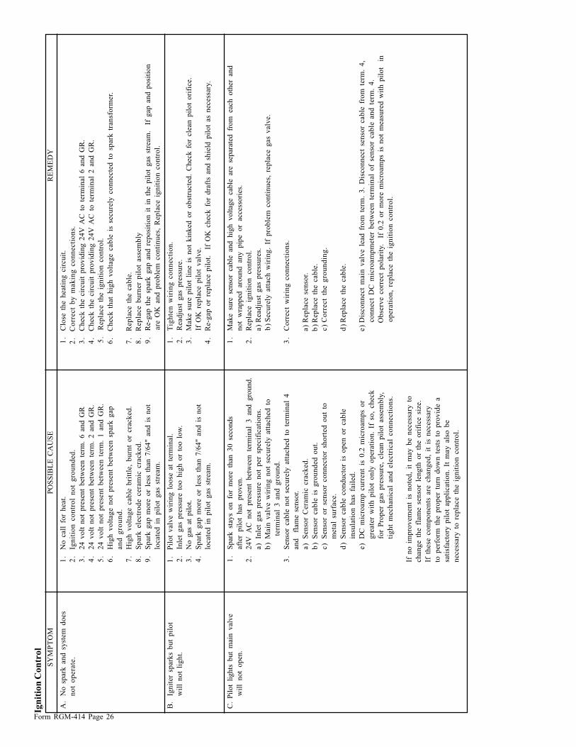
Form RGM-414 Page 26
Ign
itio
n C
on
tro
l
SY
MP
TO
MP
OS
SIB
LE
CA
US
ER
EM
ED
Y
A.
No
sp
ark
an
d s
yst
em
do
es
1.
No
call
fo
r h
eat.
1.
Clo
se t
he h
eati
ng
cir
cu
it.
no
t o
pera
te.
2.
Ign
itio
n c
on
tro
l n
ot
gro
un
ded
.2
.C
orr
ect
by
mak
ing
co
nn
ecti
on
s.
3.
24
vo
lt n
ot
pre
sen
t b
etw
een
ter
m.
6 a
nd
GR
3.
Ch
eck
th
e ci
rcu
it p
rov
idin
g 2
4V
AC
to
ter
min
al 6
an
d G
R.
4.
24
vo
lt n
ot
pre
sen
t b
etw
een
ter
m.
2 a
nd
GR
.4
.C
hec
k t
he
circ
uit
pro
vid
ing
24
V A
C t
o t
erm
inal
2 a
nd
GR
.
5.
24
vo
lt n
ot
pre
sen
t b
etw
een
term
. 1
an
d G
R.
5.
Rep
lace t
he i
gn
itio
n c
on
tro
l.
6.
Hig
h v
olt
ag
e n
ot
pre
sen
t b
etw
een
sp
ark
gap
6.
Ch
eck
th
at
hig
h v
olt
ag
e c
ab
le i
s se
cu
rely
co
nn
ecte
d t
o s
park
tra
nsf
orm
er.
an
d g
rou
nd
.
7.
Hig
h v
olt
ag
e c
ab
le b
ritt
le,
bu
rnt
or
cra
ck
ed
.7
.R
ep
lace t
he c
ab
le.
8.
Sp
ark
ele
ctr
od
e c
era
mic
cra
ck
ed
.8
.R
ep
lace b
urn
er
pil
ot
ass
em
bly
9.
Sp
ark
gap
mo
re o
r le
ss t
han
7/6
4"
and
is
no
t9
.R
e-g
ap t
he
spar
k g
ap a
nd
rep
osi
tio
n i
t in
th
e p
ilo
t g
as s
trea
m.
If
gap
an
d p
osi
tio
n
locate
d i
n p
ilo
t g
as
stre
am
.are
OK
an
d p
rob
lem
co
nti
nu
es,
Rep
lace i
gn
itio
n c
on
tro
l.
B.
Ign
iter
spark
s b
ut
pil
ot
1.
Pil
ot
valv
e w
irin
g l
oo
se a
t te
rmin
al.
1.
Tig
hte
n w
irin
g c
on
necti
on
.
wil
l n
ot
lig
ht.
2.
Inle
t g
as
pre
ssu
re t
oo
hig
h o
r to
o l
ow
.2
.R
ead
just
gas
pre
ssu
re.
3.
No
gas
at
pil
ot.
3.
Mak
e s
ure
pil
ot
lin
e i
s n
ot
kin
ked
or
ob
stru
cte
d.
Ch
eck
fo
r cle
an
pil
ot
ori
fice.
4.
Sp
ark
gap
mo
re o
r le
ss t
han
7/6
4"
and
is
no
tIf
OK
rep
lace
pil
ot
val
ve.
loca
ted
in
pil
ot
gas
str
eam
.4
.R
e-g
ap o
r re
pla
ce p
ilo
t.
If O
K c
hec
k f
or
dra
fts
and
sh
ield
pil
ot
as n
eces
sary
.
C.
Pil
ot
lights
but
mai
n v
alve
1.
Spar
k st
ays
on fo
r m
ore
th
an 30 se
conds
1.
Mak
e su
re se
nso
r ca
ble
an
d hig
h volt
age
cable
ar
e se
par
ated
fr
om
ea
ch oth
er an
d
wil
l not
open
.af
ter
pil
ot
has
pro
ven
.not
wra
pped
ar
ound an
y pip
e or
acce
ssori
es.
2.
24V
A
C not
pre
sent
bet
wee
n te
rmin
al 3 an
d gro
und.
2.
Rep
lace
ig
nit
ion
co
ntr
ol.
a)
Inle
t g
as
pre
ssu
re n
ot
per
specif
icati
on
s.a
)R
ead
just
gas
pre
ssu
res.
b)
Main
valv
e w
irin
g n
ot
secu
rely
att
ach
ed
to
b)
Secu
rely
att
ach
wir
ing
. If
pro
ble
m c
on
tin
ues,
rep
lace g
as
valv
e.
term
inal
3 a
nd
gro
un
d.
3.
Sen
sor
cab
le n
ot
secu
rely
att
ach
ed
to
term
inal
43
.C
orr
ect
wir
ing
co
nn
ecti
on
s.
and
fl
ame
sen
sor.
a)
Sen
sor
Cera
mic
cra
ck
ed
.a
)R
ep
lace s
en
sor.
b)
Sen
sor
cab
le i
s g
rou
nd
ed
ou
t.b
)R
ep
lace t
he c
ab
le.
c)
Sen
sor
or
sen
sor
co
nn
ecto
r sh
ort
ed
ou
t to
c)
Co
rrect
the g
rou
nd
ing
.
meta
l su
rface.
d)
Sen
sor
cab
le c
on
du
cto
r is
op
en
or
cab
led
)R
ep
lace t
he c
ab
le.
insu
lati
on
has
fail
ed
.
e)
DC
mic
roam
p c
urr
en
t is
0.2
mic
roam
ps
or
e)
Dis
co
nn
ect
main
valv
e l
ead
fro
m t
erm
. 3
. D
isco
nn
ect
sen
sor
cab
le f
rom
term
. 4
,
gre
ate
r w
ith
pil
ot
on
ly o
pera
tio
n.
If s
o,
ch
eck
co
nn
ect
DC
mic
roam
pm
ete
r b
etw
een
term
inal
of
sen
sor
cab
le a
nd
term
. 4
.
for
Pro
per
gas
pre
ssu
re,
cle
an
pil
ot
ass
em
bly
,O
bse
rve c
orr
ect
po
lari
ty.
If
0.2
or
mo
re m
icro
am
ps
is n
ot
measu
red
wit
h p
ilo
t i
n
tig
ht
mech
an
ical
an
d e
lectr
ical
co
nn
ecti
on
s.o
pera
tio
n,
rep
lace t
he i
gn
itio
n c
on
tro
l.
If n
o i
mp
rov
em
en
t is
no
ted
, it
may
be n
ecess
ary
to
ch
an
ge t
he f
lam
e s
en
sor
len
gth
or
the o
rifi
ce s
ize.
If t
hese
co
mp
on
en
ts a
re c
han
ged
, it
is
necess
ary
to p
erf
orm
th
e p
rop
er
turn
do
wn
test
s to
pro
vid
e a
sati
sfacto
ry p
ilo
t ap
pli
cati
on
. It
may
als
o b
e
necess
ary
to
rep
lace t
he i
gn
itio
n c
on
tro
l.

Form RGM-414 Page 27
Ma
xit
rol-
Reg
ula
tor
SY
MP
TO
MP
OS
SIB
LE
CA
US
EF
IEL
D T
ES
TR
EM
ED
Y
A.
Au
tom
ati
c c
on
tro
l1
.F
au
lty
au
tom
ati
c c
on
tro
l v
alv
e.
1.
Rem
ov
e w
ire f
rom
valv
e,
if v
alv
e d
oesn
’t c
lose
—v
alv
e i
s fa
ult
y.
1.
Rep
lace a
uto
mati
c c
on
tro
l v
alv
e.
val
ve
wil
l n
ot
clo
se2
.In
stall
ati
on
wir
ing
err
or.
2.
Rem
ov
e w
ire f
rom
am
pli
fier
term
inal
10
an
d 1
1.
If v
alv
e r
em
ain
s2
.C
orr
ect
wir
ing
.
desp
ite f
ull
ran
ge o
fo
pen
ch
eck
fo
r m
isw
irin
g.
mo
du
lati
ng
vo
ltag
e3
.A
mp
lifi
er
is f
au
lty.
3.
If A
C v
olt
age
wil
l n
ot
dro
p t
o z
ero
at
term
inal
s 8
an
d 1
1 w
hen
3.
Rep
lace a
mp
lifi
er.
at t
erm
inal
s 1
an
d 2
.D
C v
olt
age
at t
erm
inal
s 1
an
d 2
is
abo
ve
20
V D
C,
amp
lifi
er i
s
fau
lty.
If
spac
e te
mp
erat
ure
is
less
th
an 6
0°
or
gre
ater
th
an 8
5°
F,
see G
as
Fu
rnace C
on
tro
ls,
pag
e 1
8.
B.
Au
tom
ati
c c
on
tro
l1
.F
au
lty
au
tom
ati
c c
on
tro
l v
alv
e.
1.
Rea
d v
olt
age
acro
ss v
alv
e te
rmin
als.
If
24
V A
C,
val
ve
is f
ault
y.
1.
Rep
lace a
uto
mati
c c
on
tro
l v
alv
e.
valv
e w
ill
no
t o
pen
2.
Op
en
wir
e t
o a
uto
mati
c v
alv
e.
2.
Read
vo
ltag
e a
cro
ss t
erm
inals
8 a
nd
11
on
am
pli
fier.
If
24
V A
C,
2.
Co
rrect
wir
ing
.
desp
ite f
ull
ran
ge o
fch
eck
fo
r o
pen
cir
cu
it t
o a
uto
mati
c v
alv
e.
If s
pace t
em
pera
ture
is
mo
du
lati
ng
vo
ltag
ele
ss t
han
60
° o
r g
reat
er t
han
85
°F.
at t
erm
inal
s 1
an
d 2
.3
.A
mp
lifi
er i
s fa
ult
y.
3.
If A
C v
olt
age
read
ing
rem
ain
s ze
ro w
hen
DC
vo
ltag
e at
ter
min
als
3.
Rep
lace a
mp
lifi
er.
1 a
nd
2 i
s b
elo
w 1
4V
DC
, am
pli
fier
is
fau
lty.
If
spac
e te
mp
erat
ure
is l
ess
than
60
° o
r g
reat
er t
han
85
°F.
C.
No
gas
flo
w.
1.
Fau
lty
po
wer
sup
ply
.1
.R
ead
vo
ltag
e at
am
pli
fier
ter
min
als
8 a
nd
14
(2
4 V
AC
).1
.P
ow
er s
up
ply
mu
st b
e 2
4V
AC
.
2.
MR
valv
e i
nst
all
ed
back
ward
.2
.A
rro
w o
n M
R v
alv
e s
ho
uld
po
int
in d
irecti
on
of
gas
flo
w.
2.
Inst
all
pro
perl
y.
D.
Co
nti
nu
ou
s h
igh
fir
e.
1.
Ro
om
Ov
err
ide T
herm
ost
at,
1.
Rem
ov
e T
11
5 w
ires
fro
m a
mp
lifi
er
term
inals
3 a
nd
14
.1
.If
pro
per
op
era
tio
n i
s o
bta
ined
,
if u
sed
, ca
lls
for
hea
t.ch
eck
th
erm
ost
at
wir
ing
fo
r
sho
rts.
Ro
tate
th
erm
ost
at
dia
l
ab
ov
e a
nd
belo
w r
oo
m t
em
pera
-
ture
to
pro
ve
therm
ost
at
fun
cti
on
.
2.
Op
en
cir
cu
it i
n s
en
sin
g a
nd
2.
Dis
co
nn
ect
an
d m
easu
re a
cro
ss w
ires
co
nn
ecte
d t
o a
mp
lifi
er
2.
If a
bo
ve 1
2,0
00
oh
ms
ch
eck
sett
ing
cir
cu
it.
be t
erm
inals
3 a
nd
4 (
A1
01
0).
Sh
ou
ld r
ead
betw
een
8,0
00
an
dcir
cu
it f
or
op
en
or
loo
se w
ires.
12
,00
0 o
hm
s.
E.
Co
nti
nu
ou
s h
igh
fir
e b
ut
1.
Op
en
cir
cu
it i
n w
irin
g t
o M
R v
alv
e.
1.
Ch
eck
wir
ing
fo
r d
efe
cts
.1
.R
ep
lace w
irin
g i
f n
ecess
ary
.
au
tom
ati
c v
alv
e c
ycle
s.2
.P
lun
ger
jam
med
or
inst
all
ed
2.
Plu
ng
er
sho
uld
be s
mo
oth
an
d c
lean
an
d o
pera
te f
reely
2.
Cle
an
or
rep
lace p
lun
ger.
up
sid
e d
ow
n.
in s
ole
no
id s
leev
e.
3.
Fau
lty
MR
valv
e.
3.
Measu
re v
olt
ag
e a
cro
ss M
R v
alv
e.
3.
If
mo
du
lati
ng
vo
ltag
es
are
ob
tain
ed
, b
ut
no
gas
mo
du
la-
tio
n,
MR
val
ve
is f
ault
y.
Rep
lace i
f n
ecess
ary
.
F.
Fu
rnace w
on
’t a
cti
vate
1.
Sh
ort
cir
cu
it i
n s
en
sin
g a
nd
1.
Dis
co
nn
ect
an
d m
easu
re a
cro
ss w
ires
co
nn
ecte
d t
o a
mp
lifi
er
1.
If b
elo
w 8
,00
0 o
hm
s ch
eck
du
e t
o c
on
stan
t h
igh
sett
ing
cir
cu
it.
term
inals
3 a
nd
4 (
A1
01
0 m
od
els
). S
ho
uld
read
betw
een
8,0
00
cir
cu
it f
or
sho
rts
or
mis
wir
ing
.
mo
du
lati
ng
vo
ltag
ean
d 1
2,0
00
oh
ms.
(ab
ov
e 1
7 V
DC
)

Form RGM-414 Page 28
Reznor is registered in at least The United States. All registered marks are the property of their respective organization.©2000 Thomas & Betts Corporation, All rights reserved. Printed in the U.S.A.MANUFACTURER OF GAS, OIL, ELECTRIC HEATING AND VENTILATING SYSTEMS9/01 POD YL8230 Form RGM 414 (Version .02)
Maxit
rol-
Reg
ula
tor
(con
tin
ued
)
SY
MP
TO
MP
OS
SIB
LE
CA
US
EF
IEL
D T
ES
TR
EM
ED
Y
G.
Co
nti
nu
ou
s lo
w o
r1
.H
eat
load
req
uir
es l
ow
fir
e o
nly
.1
.In
cre
ase
tem
pera
ture
sett
ing
10
deg
rees.
1.
If h
eate
r g
oes
to h
igh
fir
e,
med
ium
fir
e, b
ut
syst
em
is
wo
rkin
g c
orr
ectl
y.
au
tom
ati
c v
alv
e2
.P
lun
ger
an
d/o
r m
ax
imu
m s
pri
ng
2.
Ch
eck
fo
r p
art
s.2
.In
stall
co
rrect
part
s.
cy
cle
s co
rrectl
y.
mis
sin
g.
3.
Jam
med
plu
ng
er.
3.
Ex
am
ine.
Plu
ng
er
sho
uld
be c
lean
, sm
oo
th,
an
d o
pera
te f
reely
3.
Cle
an,
or
rep
lace
plu
ng
er i
f
in s
ole
no
id s
leev
e.
necess
ary
.
4.
Oth
er
valv
es
fau
lts.
4.
Rem
ov
e w
ire f
rom
MR
valv
e.
4.
If M
R v
alv
e re
mai
ns
on
lo
w f
ire,
valv
e m
ay
be f
au
lty.
Ch
eck
ite
m
19
bel
ow
, th
en r
epla
ce v
alv
e if
necess
ary
.
5.
Inad
eq
uate
su
pp
ly p
ress
ure
. 5
.R
em
ov
e m
ax
. ad
just
men
t sp
rin
g f
rom
MR
valv
e,
pu
sh d
ow
n5
.C
heck
fo
r o
bst
ructi
on
in
gas
pip
e
on
plu
ng
er.
In
suff
icie
nt
man
ifo
ld p
ress
ure
wit
h f
urn
ace o
pera
tin
gah
ead
of
con
tro
ls.
In
crea
se g
as
ind
icat
es s
up
ply
is
too
lo
w.
pre
ssu
re i
f p
oss
ible
.
H.
Inco
rrect
dis
ch
arg
e1
.C
ali
bra
tio
n.
1.
Ch
eck
seal
on
cali
bra
tio
n p
ote
nti
om
ete
r.1
.R
ecali
bra
te p
er
“T
em
pera
ture
air
tem
pera
ture
.C
ali
bra
tio
n” p
roced
ure
.
I.E
rrati
c o
r se
vere
ly1
.D
irty
or
stic
kin
g p
lun
ger.
1.
Ex
am
ine.
Plu
ng
er
sho
uld
be c
lean
, sm
oo
th,
an
d o
pera
te f
reely
in
1.
Cle
an o
r re
pla
ce p
lun
ger
if
pu
lsati
ng
fla
me.
sole
noid
sle
eve.
necess
ary
.
2.
Lo
ose
or
bro
ken
wir
ing
.2
.In
spect
wir
ing
.2
.C
orr
ect
wir
ing
.
3.
Err
ati
c D
C v
olt
ag
e.
3.
Ob
serv
e D
C v
olt
age
acro
ss a
mp
lifi
er t
erm
inal
s 1
an
d 2
.3
.If
err
ati
c o
r p
uls
ati
ng
DC
vo
ltag
e
is o
bse
rved
and w
irin
g s
how
s no
defe
cts
, re
pla
ce a
mp
lifi
er.
If
err
ati
c o
r p
uls
ati
ng
vo
ltag
e
co
nti
nu
es,
co
nta
ct
the m
fg.
*C
ontr
ol
circ
uit
s ex
tern
al to
th
e M
axit
rol-
Reg
ula
tor
and A
mpli
fier
ca
n ca
use
burn
er m
alfu
nct
ion.
Alw
ays
chec
k gas
val
ve
to be
cert
ain it
is
tu
rned
on,
and ch
eck li
mit
co
ntr
ols
fo
r n
orm
al
op
era
tio
n.