pacificorp lm2-18 site photos north umpqua …€¦ · north umpqua hydroelectric project ferc...
TRANSCRIPT
03/11/2004 Revised: 6/28/2002
PacifiCorpNorth Umpqua Hydroelectric Project
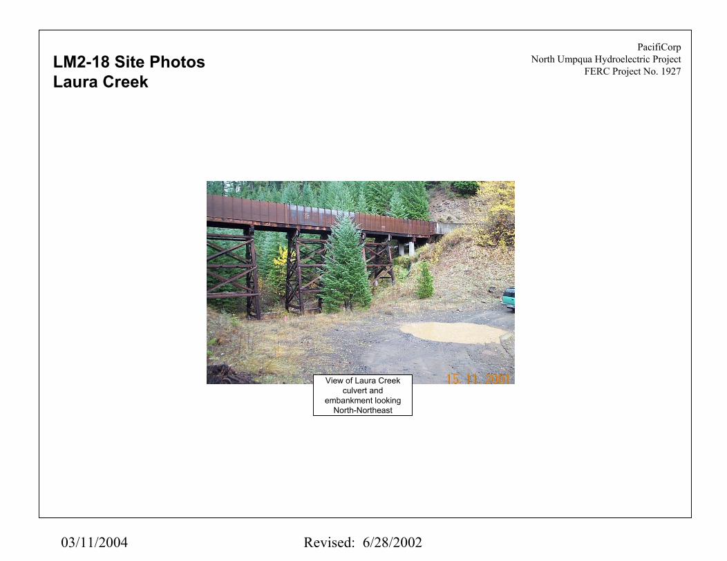
FERC Project No. 1927LM2-18 Site PhotosLaura Creek
View of Laura Creekculvert and
embankment lookingNorth-Northeast

03/11/2004 Revised: 6/28/2002
PacifiCorpNorth Umpqua Hydroelectric Project
FERC Project No. 1927LM2-18 Site PhotosLaura Creek
View of road along canallooking upstream
towards Laura Creek
Over-steep slopesbelow access road
6’ high Gabion wall

North Umpqua Hydroelectric Project (FERC 1927)Erosion Control PlanSite Remediation/ Assessment Form
HighLat: Long:
2 43' 20.494" 122' 17.773" Project Development: Lemolo 2 3Nearest Project Feature: Waterway Structure Type: Access Road
Approx. units unitquantity price Costs (2001$)
1,000 CY900 CY100 SF
25 CY10 CY15 CY50 LF20 CY
4,200 SF4,200 SF
Data Collection Information: Mass Bal Borrow CYTeam: Weather: Excess Fill 915 CYDate: 15-Nov-01 Time: 10:00am Waste 100 CY
Locator Information/GPSGPS shows 21' accuracy
Hanek, Moen, Hansen Overcast, 45 degrees
Revegetation
Slope Revegetation Jute Matting
Place gabion baskets 3' high Stone fill in baskets
Spread compact backfill Use as padding material (or stockpile)
Gabion Wall 3'x50' Excavate for tie backs
Use as padding material (or stockpile) Waste disposal
Description of Concern: Cutslope failures above canal and sidecast failures below. Site is west of Potter Creek.
Proposed Remediation: Selectively remove sidecast from approximately 275 ft of access road, in areas shown on sketch. Extend existing gabion wall 50 feet further to the east. Gabion wall is located approximately 400 feet west of the transition between gunite lined canal and double wall concrete flume.
Remediation Task Breakdown: Estimated Additional Comments/Sketches
Leave 6" and larger diameter trees and their roots undisturbed. Design efforts will include review of draft designs by agency personnel as part of the normal implementation process. Final designs may result in modifications to the dimensions and limits of the proposed treatments.
Areas where ground is disturbed by construction will be protected with jute mats or other comparable erosion control measures until vegetation planting or other ground cover is provided in accordance with the VMP.
Sidecast Removal Excavation
StartRisk Rating Reference Point
End
Site # LM2-19 Priority Ranking
Impact Rating
Printed: 03/11/2004 Revised: 3/4/2004

03/11/2004 Revised: 6/28/2002
PacifiCorpNorth Umpqua Hydroelectric Project
FERC Project No. 1927
15’
Section ANTS
1.5:1
10’
Canalaccess
road
5:1
3’
Revegetate side castremoval slope in
accordance with vegetationmanagement plan t.b.d.
‘Typical’ sidecast removalDo not remove 6” diameter or larger trees
LM2-19 Site Plan
N
2500
Scale in feet
Noremoval
Remove ‘typical’sidecast section
along 150-ft sectionof access road,
leave trees in place
Gunite-LinedCanal
2-WallConcrete Flume
Existing gabionwall to remain
Remove ‘typical’sidecast sectionSee Section A
Base map from ProjectBoundary maps
Exhibit G of licenseapplication
Existingpropane tank
to remain
150’
Existing gabion wallto be extended 50 ft
to east

03/11/2004 Revised: 6/28/2002
PacifiCorpNorth Umpqua Hydroelectric Project
FERC Project No. 1927LM2-19 Site Photo
View along canal atbeginning of sectionwith selective sidecast removal. Pinkstake indicates thestart of the sidecast
removal section.

North Umpqua Hydroelectric Project (FERC 1927)Erosion Control PlanSite Remediation/ Assessment Form
High (5)Lat: Long:
5Project Development: Lemolo 2 5 43' 20.630" 122' 17.975"Nearest Project Feature: Waterway Structure Type: Steel Flume, Canal, Spillway
Approx. units unitquantity price Costs (2001$)
2 CY220 CY
15,000 CY14,000 CY
1,000 CY23,000 SF
3,900 CY3,500 CY
400 CY
40,000 SF81 EA
Data Collection Information: Mass Bal Borrow CYTeam: Weather: Excess Fill 17,900 CYDate: 15-Nov-01 Time: 12:00pm Waste 1,882 CY
Site # LM2-20 Priority Ranking
Impact Rating StartRisk Rating Reference Point
EndDescription of Concern: Potter Creek. Unstable slopes above and below canal on west side of creek. Potential for debris flows in Potter Creek channel. Erosion at end of gunite channel in Potter Creek below crossing of waterway flume. Potential for boulders rolling down west slope to bounce into canal and damage flume wall and/or cause overflow.
Proposed Remediation: Place mesh on portion of slope above flume to reduce velocity of boulders rolling down slope. Remove sidecast for 400 ft length on west side of creek, install gabion wall (estimated height 9 ft) along entire 400 ft section. On uphill side of flume structure, place 3 ft high gabion wall to provide protection against boulder impact. Restore original channel in Potter Creek and remove gunite section (see sketch). Revegetate Disturbed slopes as needed.
Remediation Task Breakdown: Estimated Additional Comments/Sketches
Site is at Potter Creek
Aquatic connectivity site L23 is located within the area of this site. Issues related to future modifications planned to restore aquatic connectivity at this site have not been taken into account in evaluatingthe need for additional erosion mitigation measures. This is also a proposed location for a 30-minute waterway drainage pipe. Additional engineering investigations and designs to be completed fordrainage pipes. Design efforts will include review of draft designs byagency personnel as part of the normal implementation process. Finadesigns may result in modifications to the dimensions and limits of the proposed treatments.
Final design will also consider the need for upgrading the location where seepage crosses the access road to an engineered driveable dip.
(Cont. on next page)
Concrete Demolition Potter Creek Diversion Dam Gunite Channel LiningStreambed Restoration Excavate channel Excess fill to stockpile Waste disposal Restoration work (large wood, rocks)Sidecast Removal (U/S & D/S Sections) Excavation Use as padding material (or stockpile) Waste disposalRockfall Fence
Locator Information/GPSGPS shows 24' accuracy
Hanek, Moen, Hansen Overcast, 45 degrees
(Cont. on next page)
Rockfall Fence 400' long X 100' high Anchors (2 per 10' mesh section)
Pritned: 03/11/2004 Revised: 3/4/2004

North Umpqua Hydroelectric Project (FERC 1927)Erosion Control PlanSite Remediation/ Assessment Form
HighLat: Long:
3Project Development: Lemolo 2 3 43' 20.630" 122' 17.975"Nearest Project Feature: Waterway Structure Type: Steel Flume, Canal, Spillway
Approx. units unitquantity price Costs (2001$)
1,500 CY1,100 CY
400 CY7,200 SF
400 LF600 LF600 CY
40 CY220 CY200 EA
27 CY44,000 LB20,000 LB
8 CY960 SF
13,000 SF13,000 SF
3,000 SF3,000 SF
30,000 SF30,000 SF
Data Collection Information: Mass Bal Borrow CYTeam: Weather: Excess Fill 17,900 CYDate: 15-Nov-01 Time: 12:00pm Waste 1,882 CY
Hanek, Moen, Hansen Overcast, 45 degrees
Reference PointEnd
Remediation Task Breakdown: Estimated Additional Comments/Sketches
Areas where ground is disturbed by construction will be protected with jute mats or other comparable erosion control measures until vegetation planting or other ground cover is provided in accordance with the VMP. Leave 6" and larger dia. trees and their roots undisturbed during sidecast removal.
(Cont.)Gabion Walls 9'x400' & 3'x600'
Priority Ranking Locator Information/GPSGPS shows 24' accuracy
Site # LM2-20(Cont.) Impact Rating Start
Risk Rating
Excavate for tie backs Spread compact backfill Use as padding material (or stockpile) Place wire mesh tie-backs Place gabion baskets 9' high Place gabion baskets 3' high Stone fill in basketsNew Steel Flume
Rock Dowel
Demolish Existing Concrete Flume Demolish Existing Concrete Channel/Spillway
Concrete Pads New Steel Flume New Steel TrestleNew Access Road Bridge Bridge Abutments Steel Bridge Deck 40' X 24'
Jute Matting (U/S Sidecast)
Slope Revegetation Jute Matting (D/S Sidecast) Revegetation (D/S Sidecast)
Revegetation (Streambed)
Revegetation (U/S Sidecast) Jute Matting (Streambed)
Pritned: 03/11/2004 Revised: 3/4/2004

03/11/2004 Revised: 6/28/2002
PacifiCorpNorth Umpqua Hydroelectric Project
FERC Project No. 1927
LM2-20 Site PlanPotter Creek
N
Base map from ProjectBoundary maps
Exhibit G of licenseapplication
5000
Scale in feet North Umpqua River
Potter Creek
Remove gunite-linedchannel, excavate fill from
former channel andrestore with boulders and
woody debris
Place rock netting over 100by 400-ft section of slope
above canal. Location to befield verified.
A
A
BB
Remove sidecast,along 400-ft length,Install gabion wall,
see Section A
Place 3-ft high gabion basketon upslope side of flume, fillwith existing rock from site.
See Detail ARegrade and restore
stream channel belowgunite-lined section
PacifiCorpNorth Umpqua Hydroelectric Project
FERC Project No. 1927
New 80-ft long steelflume on trestle for
waterway crossing ofPotter Creek
New 40-ft long bridgefor access road
crossingSee Section C
CC
Possible location for30-minute waterway
drainage pipe.
L23

03/11/2004 Revised: 6/28/2002
PacifiCorpNorth Umpqua Hydroelectric Project
FERC Project No. 1927
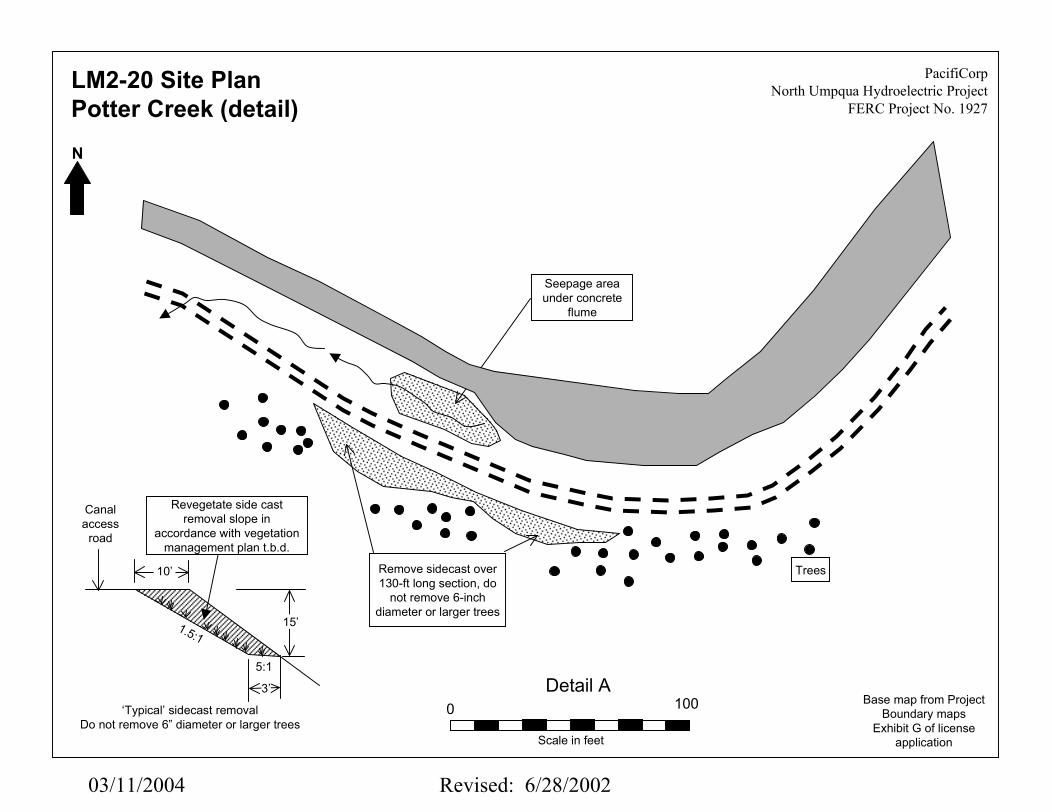
LM2-20 Site PlanPotter Creek (detail)
N
Base map from ProjectBoundary maps
Exhibit G of licenseapplication
Section ANTS
15’1.5:1
15’
Canalaccess
road
3’
0.9:1
Gabion basket, 3 ft high,placed in areas not coveredby mesh to protect against
rolling boulders
Rockfall mesh to retardmovement of boulders rolling
down slope above canal,anchored at top of slope
Remove sidecast along400 ft of access road,construct gabion wall,
avg. height 9 ft.
Remove gunite liningand excavate fill to
restore original channel
Existinggroundsurface
Original groundsurface (estimated)
Gunite-lined
channel
Section BNTS
10’
70’

03/11/2004 Revised: 6/28/2002
PacifiCorpNorth Umpqua Hydroelectric Project
FERC Project No. 1927
LM2-20 Site PlanPotter Creek (detail)
N
Base map from ProjectBoundary maps
Exhibit G of licenseapplication
Cross-section showing removal ofexisting gunite-lined channel andaccess road bridge including abutmentstructures and precast deck
Remove gunite-lined channeland restore original channel
bridge deck
Pre-cast concretebridge deck
Cast-in-placeconcrete pier
Original streamchannel
(approximate)
Temporaryexcavation for
pier footing
Section CNTS
03/11/2004 Revised: 6/28/2002
PacifiCorpNorth Umpqua Hydroelectric Project
FERC Project No. 1927
LM2-20 Site PlanPotter Creek (detail)N
Base map from ProjectBoundary maps
Exhibit G of licenseapplication
Detail A1000
Scale in feet
Seepage areaunder concrete
flume
TreesRemove sidecast over130-ft long section, do
not remove 6-inchdiameter or larger trees
15’
10’
Canalaccess
road
5:1
3’
Revegetate side castremoval slope in
accordance with vegetationmanagement plan t.b.d.
‘Typical’ sidecast removalDo not remove 6” diameter or larger trees
1.5:1

03/11/2004 Revised: 6/28/2002
PacifiCorpNorth Umpqua Hydroelectric Project
FERC Project No. 1927LM2-20 Site PhotosPotter Creek
Approximately 9’ highGabion wall over
approximately 400’ ofslope below access road
View of West side ofPotter Creek from
East side
View of West side ofPotter Creek from near
creek crossing
Gabion rockfall protectionwall above canal
Rockfall protection meshover approximately 400’
of slope above canal

03/11/2004 Revised: 6/28/2002
PacifiCorpNorth Umpqua Hydroelectric Project
FERC Project No. 1927LM2-20 Site PhotosPotter Creek
View of East side of PotterCreek near seepage area
where there will be selectivesidecast removal

03/11/2004 Revised: 6/28/2002
PacifiCorpNorth Umpqua Hydroelectric Project
FERC Project No. 1927LM2-20 Site PhotosPotter Creek
Potter Creek Inlet structureinto the canal system, to beremoved as part of stream
restoration effort
Potter Creek gunite linedspillway canal, to be
removed as part of streamrestoration effort

PacifiCorp N. Umpqua Project Rev 6/14/02
O:\Xchange\Xchg-archv\Numpqua\ECP2003\ECP Sites\Lemolo 2\LM2-20 PotterCrCost1.docWashington Infrastructure Page 1 of 2
POTTER CREEK - STREAM RESTORATIONAT LEMOLO NO.2 CANAL, SITE LM2-20
A. General Description and Cost Considerations
1. Preparatory Work1.1 Mobilize Contractor and Construction Equipment1.2 Clear Vegetation on Flat Portions of Potter Creek, est avg 200’ by 1,000’
2. Diversion during construction – Sandbag Cofferdam and Continuous Pumping3. Demolish Existing Concrete at Potter Creek Diversion Dam Abutments – Volume =
0.5’th x 4’h x20’l = 40 cubic feet = 1.5 cubic yards;4. Demolish Concrete & Shotcrete Lining of Potter Creek Channel – Volume = 20’ w
surface x 600’ long x 0.5’ avg th = 6,000 cubic feet = 222 cubic yards (Surface Area= 20’ x 600’ = 12,000 SF)
5. Build New Steel Flume to replace portion of canal horseshoe bend5.1 Cross-section dimensions:
5.1.1 Wall Height – 7.5’5.1.2 Bottom Width – 11.4’5.1.3 Wall Plate Thickness – Assume ½”5.1.4 Overall Length – Assume 80’
5.2 Weight of Steel for Flume = (7.5+11.4+7.5)’ wide x 80’ long x .042’ thick =88.70 cubic feet x 490 lbs/cf = 43,463 pounds
5.3 Weight of steel for trestle supports – assume 20,000 pounds6. Concrete Foundation for steel trestles
6.1 Assume Concrete Pads - 3 feet high, 2 feet thick, 12 feet long (assume 10 needed-Concrete Volume = 5x3’x2’x12’ = 360 cubic feet = 26.6 cubic yards
6.2 Rock Doweling Required – assume 200 dowels for all 10 pads;7. Connect Steel Flume to Concrete Canal
7.1 Dewater Canal 7.2 Saw Cut ends of canal to join steel flume – 2 @ (7.5+11.4+7.5)’ x 12” depth =
633.6 Inch-Feet of Depth7.3 Demolish cut portion of concrete canal – (7.5+11.4+7.5)’ x 40’ x 1’ = 1,056 cubic
feet = 39 cubic yards – use rubble as riprap7.4 Place Steel Flume on Trestle and grout connection with concrete canal7.5 Resume operation of Lemolo No. 2 canal
8. Excavate Potter Creek channel to original or uniform grade slope8.1 Assume average trapezoidal cross-section for 600’ length
8.1.1 Top width = 75’8.1.2 Bottom width = 12’8.1.3 Average Height = 15’
8.2 Volume of Excavation = ½ x (75+12)’ x 15’ x 600’= 391,500 cubic feet = 14,500cubic yards
9. Streambed restoration, 15’ wide stream bed improved over 1500’ of length 22,500 sfof restored area to include large woody debris and stream bed gravels

PacifiCorp N. Umpqua Project Rev 6/14/02
O:\Xchange\Xchg-archv\Numpqua\ECP2003\ECP Sites\Lemolo 2\LM2-20 PotterCrCost1.docWashington Infrastructure Page 2 of 2
10. Replace Existing Road Bridge with longer span bridge10.1 Assume Length of bridge = 40’10.2 Assume minimal concrete abutments, say 4 cubic yards each
11. Gabion Wall, 3’ high by 600’ long = 1,800 sf11.1 Build Gabions11.2 Place Fill on Upslope side of gabions
12. D/S Slope Protection 12.1 Wire Mesh slope protection, 400’ x 100’ = 40,000 sf of mesh 12.2 Anchors for wire mesh panels assume 10’ sections, with 2 anchor per section
total of 81 anchors13 Sidecast fill removal and revetment
13.1 D/S section 15’ along top, 15’ deep with a 3’ bench assume total area of cut (½x (15’+24’))x9’+(½ x (24’+3’))x3’x400’ = 86,400 CF = 3,200 CY
13.2 U/S section (½ x (15’+3’))x15’x130’ = 17,550 SF = 650 CY13.3 Gabion wall 9’ high by 400’ long = 3,600 SF
14 Re-vegetate Exposed Slopes 14.1 D/S Sidecast Surface Area = 32’ x 400’ = 12,800 SF 14.2 U/S Sidecast Surface Area = 24’ x 130’ = 3,120 SF 14.3 Creek Restoration Surface Area = 60’ x 500’ = 30,000 SF
15 Additional Cost Input15.1 Contractor Demobilization15.2 Owner’s Engineering and Design15.3 Owner’s Construction Inspection15.4 Owner’s Permitting15.5 Contingency Allowance
B. Estimated Construction Schedule
Based on the estimated quantities and selected equipment spreads to perform the workshown in the construction cost estimate, the scope of construction work identified abovecould be completed in a period of 50 workdays, plus contract negotiations, mobilization,demobilization, and end of project punchlist work. A reasonable total duration time tosuccessfully perform this construction work is about 12 weeks during the summer or fallmonths. This amount of time is for construction fieldwork, and does not include shoptime for steel fabrication.

North Umpqua Hydroelectric Project (FERC 1927)Erosion Control PlanSite Remediation/ Assessment Form
HighLat: Long:
3Project Development: Lemolo 2 2 43' 20.886" 122' 17.463" Nearest Project Feature: Waterway Structure Type: Canal, Access Road, Culvert
Approx. units unitquantity price Costs (2001$)
240 CY20 CY
300 CY62 CY
6 CY55 FT60 CY20 CY30 CY
20 CY18 CY
2 CY
50 FT1 CY
Data Collection Information: Mass Bal Borrow 62 CYTeam: Weather: Excess Fill CYDate: 15-Nov-01 Time: 2:00pm Waste 22 CY
Locator Information/GPSGPS shows 33' accuracy
Site # LM2-21 Priority Ranking
Impact Rating StartRisk Rating Reference Point
EndDescription of Concern: Two embankments, each with a culvert. On western embankment, downstream fill is oversteepened. Small gabion wall previously installed across top of fill to maintain road. Drainage pipe from flume drops water into small splash pool upstream of culvert. Culvert under eastern embankment is approx. half full of sediment. Gabion wall also constructed on east embankment. Sidecast fill present in areas between embankments. Seepage under flume.
Proposed Remediation: Western embankment - place rock on downstream side to armor slope, provide buttressing, and bring up so that culvert does not shotgun. Improve armoring at drain pipe discharge. Eastern embankment - remove and rebuild with new culvert. Capture seepage below flume and bring down to creek bed in a pipe instead of letting it run down slope beneath flume. Remove sidecast as shown on sketch.
Remediation Task Breakdown: Estimated Additional Comments/Sketches
Proposed location for 30-minute waterway drainage pipe. Additionalengineering investigations and designs to be completed for drainage pipes. Feasibility of using existing 30-inch diameter waterway drain pipe as part of the 30-minute drainage system may be examined. Design process will include review of draft designs by agency personnel as part of the normal implementation process. Final designs may result in modifications to the dimensions and limits of the proposed treatments.
Methods for placement of riprap on downstream face of western embankment to be determined during final design, but may include benching and layer placement, end dumping, clamshell or other methods.
Areas where ground is disturbed by construction will be protected with jute mats or other comparable erosion control measures until vegetation planting or other ground cover is provided in accordance with the VMP.
Culvert Crossing Excavation of existing crossing Waste disposal Fill from stockpile Fill material imported from other sites Roadbed material 1" minus pitrun New 60" culvert (field judgement) Rock buttress of culvert slope Pipe Bedding Riprap 1.5'-3' rockSidecast Removal Excavation Use as padding material (or stockpile) Waste disposalCaptured Seepage Reroute Pipe 24" CMP
Hanek, Moen, Hansen Overcast, 45 degrees
Concrete Anchor block(Cont. on next page)
Printed: 03/11/2004 Revised: 3/3/2004

North Umpqua Hydroelectric Project (FERC 1927)Erosion Control PlanSite Remediation/ Assessment Form
High (4)Lat: Long:
5Project Development: Lemolo 2 3 43' 20.886" 122' 17.463" Nearest Project Feature: Waterway Structure Type: Canal, Access Road, Culvert
Approx. units unitquantity price Costs (2001$)
5 CY
800 SF800 SF
Data Collection Information: Mass Bal Borrow 62 CYTeam: Weather: Excess Fill CYDate: 15-Nov-01 Time: 2:00pm Waste 22 CY
Hanek, Moen, Hansen Overcast, 45 degrees
Jute Matting Revegetation
Riprap 1.5'-3' rockSlope Revegetation
Risk Rating Reference PointEnd
Remediation Task Breakdown: Estimated Additional Comments/Sketches
(Cont.)Rock Under 30" Waterway Drainage Pipe
Site # LM2-21(Cont.)
Priority Ranking Locator Information/GPSGPS shows 33' accuracy
Impact Rating Start
Printed: 03/11/2004 Revised: 3/3/2004

03/11/2004 Revised: 6/28/2002
PacifiCorpNorth Umpqua Hydroelectric Project
FERC Project No. 1927LM2-21 Site PlanSally Creek
N
Scale in feet0 60
Place rock on downstream sideof existing embankment to
armor slope, existing gabionwall to remain but be buried innew rock, extend downstream
end of culvert as needed toreach toe of new fill
Trees
Access road
Existing culvertto remainPlace riprap to improve
armoring at flume drainpipe discharge
Secondarydrainage channel
Sally Creek primarydrainage channel
Base map from ProjectBoundary maps
Exhibit G of licenseapplication
Steel flume
Remove sidecast,approx. 20 cu. yds.
Remove existing easternembankment and rebuild
with new culvert.
Capture seepageunder flume and
route to creek bedthrough a pipe.
Possible location for30-minute waterway
drainage pipe.
Existing 30” dia. waterwaydrainage pipe, possibly
used as a 30-minutewaterway drainage pipe
Riprap
Riprap
The remediation planned is based onthe assumption that the culverts areadequately sized for minimum of 100
year flood flow

03/11/2004 Revised: 6/28/2002
PacifiCorpNorth Umpqua Hydroelectric Project
FERC Project No. 1927LM2-21 Site PhotosSally Creek
Place rockunder canal
drainage pipe
View of Westcreek flume
crossing
View of Eastcreek flume
crossing

03/11/2004 Revised: 6/28/2002
PacifiCorpNorth Umpqua Hydroelectric Project
FERC Project No. 1927LM2-21 Site PhotoSally Creek
Seepage observed at eastern(upstream) transition from steel
flume to concrete canal. Water tobe captured in a pipe and brought
down to the creek bed

North Umpqua Hydroelectric Project (FERC 1927)Erosion Control PlanSite Remediation/Assessment Form
High High Locator Information/GPSLat: Long:
3 3Project Development: Lemolo 2 2 2 43' 20.984" 122' 17.102" Nearest Project Feature: Waterway Structure Type: Access Road & Culvert 43' 20.948" 122' 17.252"
Approx. units unitquantity price Costs (2001$)
1,600 CY100 CY
2,000 CY500 CY
12 CY98 FT30 CY15 CY
3,800 CY3,500 CY
300 CY
270 CY200 CY
70 CY
Data Collection Information: Mass Bal Borrow CYTeam: Weather: Excess Fill 3,070 CYDate: 15-Nov-01 Time: 2:30pm Waste 400 CY
Proposed Remediation: Remove upper and lower culverts and replace lower culvert with larger culvert. (Alternative - replace upper culvert with larger diameter). Selectively remove sidecast fill both east and west of creek crossing. See sketch.
Estimated
Use as padding material (or stockpile)
Excavate for tie backs Spread compact backfill
Waste disposalGabion Wall 6' X 150'
Description of Concern: Embankment with two culverts through it. Lower culvert in stream channel has partially blocked inlet - boulders have moved in front of it. Appears undersized for volume of flow. Area around inlet is armored with boulders and near vertical. Upper culvert is clean and dry. Oversteepened sidecast fill in areas east and west of creek crossing, many areas oraveling and potential failure.
Remediation Task Breakdown: Additional Comments/Sketches
Site is at Dorothy Creek. New culvert to be sized for Q100 flow.
Proposed location for 30-minute waterway drainage pipe. Additionalengineering investigations and designs to be completed for drainage pipes. Design efforts will include review of draft designs by agency personnel as part of the normal implementation process. Final designs may include additional erosion control measures.
Sidecast to be removed selectively, leaving trees of 6-inch diameter and larger in place, and not disturbing their roots. Areas where ground is disturbed by construction will be protected with jute mats or other comparable erosion control measures until vegetation planting or other ground cover is provided in accordance with the VMP.
Excavation Use as padding material (or stockpile)
Fill from stockpile
Sidecast Removal
New 72" culvert Pipe Bedding
Roadbed material 1" minus pitrun
Riprap 1.5'-3' rock
Borrow fill from stockpile
Waste disposal
(Cont. on next page)
Site # LM2-22
Hanek, Moen, Hansen Overcast, 45 degrees
Culvert Crossing Excavation of existing crossing
EndRisk RatingImpact Rating
Priority Ranking
StartReference Point
Printed: 03/11/2004 Revised: 3/4/2004

North Umpqua Hydroelectric Project (FERC 1927)Erosion Control PlanSite Remediation/Assessment Form
High (4) High (4) Locator Information/GPSLat: Long:
5 5Project Development: Lemolo 2 3 3 43' 20.984" 122' 17.102" Nearest Project Feature: Waterway Structure Type: Access Road & Culvert 43' 20.948" 122' 17.252"
Approx. units unitquantity price Costs (2001$)
1,350 SF150 LF100 CY
24,000 SF24,000 SF
Data Collection Information: Mass Bal Borrow CYTeam: Weather: Excess Fill 3,070 CYDate: 15-Nov-01 Time: 2:30pm Waste 400 CY
Hanek, Moen, Hansen Overcast, 45 degrees
Revegetation
Place wire mesh tie-backs
Slope Revegetation Jute Matting
Place gabion baskets 6' high Stone fill in baskets
Risk Rating Reference PointEnd
Remediation Task Breakdown: Estimated Additional Comments/Sketches
Gabion Wall 6' X 150' (Cont.)
Site # LM2-22(Cont.)
Priority Ranking
Impact Rating Start
Printed: 03/11/2004 Revised: 3/4/2004

03/11/2004 Revised: 6/28/2002
PacifiCorpNorth Umpqua Hydroelectric Project
FERC Project No. 1927LM2-22 Site PlanDorothy CreekN
Base map from ProjectBoundary maps
Exhibit G of licenseapplication
5000
Scale in feet
975
0
600
100
880
Noremoval
Remove ‘typical’ sidecastsection, See Section AInstall 150 ft of 6-ft highgabion wall at locations
as needed
Remove ‘typical’sidecast section
0215
465505555
Gabion wall &sidecast removal,
See Detail,(Section B)
Remove ‘typical’sidecast section,See Section A
365
Noremoval
North Umpqua River
Dor
othy
Cre
ek
15’
Section ANTS
1.5:1
10’
Canalaccess
road
5:1
3’
Revegetate side castremoval slope in
accordance with vegetationmanagement plan t.b.d.
‘Typical’ sidecast removalDo not remove 6” diameter or larger trees
Embankment with two culverts atdifferent elevations. Replace
lower culvert with larger diameterculvert or replace upper culvert
with larger diameter culvert
A
Possible location for30-minute waterway
drainage pipe.
GPSRef.

03/11/2004 Revised: 6/28/2002
PacifiCorpNorth Umpqua Hydroelectric Project
FERC Project No. 1927LM2-22 Site PlanDorothy Creek (detail)N
Base map from ProjectBoundary maps
Exhibit G of licenseapplication
Section BNTS
15’1.5:1
12’
‘Remove sidecast below access roadConstruct gabion wall along outboard edge of road,110 ft in length, 6 ft high. Cut into slope above roadas needed to maintain 12 ft road width
Accessroad
0110 D
orot
hy C
reek
Remove ‘typical’sidecast section,Install gabion wall
Gabion wall,6 ft high,
110 ft long
Cut into slope asneeded to maintain
road width
Sidecastremoval
B
B
5:1
3’
Revegetate side castremoval slope in
accordance with vegetationmanagement plan t.b.d.

03/11/2004 Revised: 6/28/2002
PacifiCorpNorth Umpqua Hydroelectric Project
FERC Project No. 1927LM2-22 Site PhotoDorothy Creek
Dorothy Creek crossing,culvert inlet side of
embankment, upperculvert

North Umpqua Hydroelectric Project (FERC 1927)Erosion Control PlanSite Remediation/ Assessment Form
High Locator Information/GPSLat: Long:
3Project Development: Lemolo 2 3 43' 20.984" 122' 17.102" Nearest Project Feature: Waterway Structure Type: Canal, Concrete Flume, Access Road
Approx. units unitquantity price Costs (2001$)
2,500 CY2,300 CY
200 CY
24,000 SF61 EA
21,000 SF21,000 SF
Data Collection Information: Mass Bal Borrow CYTeam: Weather: Excess Fill 2,300 CYDate: 15-Nov-01 Time: 3:30pm Waste 200 CY
Site # LM2-23 Priority Ranking
Impact Rating StartRisk Rating Reference Point
EndDescription of Concern: Site starts east of Dorothy Creek, at transition from gunite lined canal to concrete flume. Oversteepened and potentially unstable sidecast below access road. Several areas of high cuts above canal, with many boulders showing in cut. Boulders fall into canal frequently, as shown by extensive spoil piles along canal.
Proposed Remediation: Selectively remove sidecast in areas shown on sketch map. Leave larger trees in place. Install mesh over upslope cut to prevent rocks from bouncing into outboard wall of canal. Install mesh over a 300-ft long section of canal where the cut is highest. Height varies from approx. 60 to 90 ft.
Remediation Task Breakdown: Estimated Additional Comments/Sketches
Aquatic connectivity sites L16, L17, L18, and L20 lie within the area of this site. Issues related to future modifications planned to restore aquatic connectivity at this site have not been taken into account in evaluating erosion mitigation measures at this site. Final design of aquatic connectivity measures at this site may result in modifications to the dimensions and limits of the proposed treatments
Prior to construction of erosion mitigation measures, agency personnel will review draft designs as part of the normal implementation process. Final designs may result in modifications to the dimensions and limits of the proposed treatments.
In areas of sidecast removal, leave 6" and larger dia. trees and their roots undisturbed. Areas where ground is disturbed will be protected with jute mats or other comparable erosion control measures until vegetation planting or other ground cover is provided in accordance with the VMP.
Sidecast Removal Excavation Use as padding material (or stockpile) Waste disposalRockfall Fence Rockfall Fence 300' long X 80' high Anchors (2 per 10' mesh section)Slope Revegetation Jute Matting Revegetation
Hanek, Moen, Hansen Overcast, 45 degrees
Printed: 03/11/2004 Revised: 3/4/2004

03/11/2004 Revised: 6/28/2002
PacifiCorpNorth Umpqua Hydroelectric Project
FERC Project No. 1927LM2-23 Site Plan
N
Base map from ProjectBoundary maps
Exhibit G of licenseapplication
5000
Scale in feet
16701600
1520
Selectively remove‘typical’ sidecast section,
leave 6” diameter andlarger trees in place
See Section A
Noremoval
A
A
1380
1350
975
0
Distance in feet as measuredalong access road, beginningat transition from gunite-lined
to 1-wall concrete flume
Noremoval
Station 1670 at point whereaccess road crosses canal onwestern side of Norma Creek
Remove ‘typical’sidecast sectionSee Section A
Place 60 to 90 ft high rocknetting along 300-ft reach ofslope above canal. Location
to be field selected.
15’
Section ANTS
1.5:1
10’
Canalaccess
road
5:1
3’
Revegetate side castremoval slope in
accordance with vegetationmanagement plan t.b.d.
‘Typical’ sidecast removalDo not remove 6” diameter or larger trees
L20
L18 L17 L16

North Umpqua Hydroelectric Project (FERC 1927)Erosion Control PlanSite Remediation/ Assessment Form
MedLat: Long:
3Project Development: Lemolo 2 1 43' 21.166" 122' 16.669" Nearest Project Feature: Waterway Structure Type: Canal, Concrete Flume, Access Road
Approx. units unitquantity price Costs (2001$)
1000 SF5 CY
90 CY12 CY
Data Collection Information: Mass Bal Borrow CYTeam: Weather: Excess Fill CYDate: 15-Nov-01 Time: 4:30pm Waste 5 CY
Site # LM2-24 Priority Ranking
Impact Rating StartRisk Rating Reference Point
EndDescription of Concern: Access road crosses Norma Creek on a small embankment. Downstream side is oversteepened and culvert is shotgunned. Culvert inlet is clear and culvert is in gooshape.
Proposed Remediation: Armor downstream side of embankment with rock, bring up to elevation of culvert outlet. Continue rock up downstream side of embankment to elevation of road, as shown on sketch.
Remediation Task Breakdown: Estimated Additional Comments/Sketches
Site is at Norma Creek. Culvert to be replaced if inadequate for Q100
flow.
Proposed location for 30-minute waterway drainage pipe. Additionalengineering investigations and designs to be completed for drainage pipes. Design efforts will include review of draft designs by agency personnel as part of the normal implementation process. Final designs may include additional erosion control measures.
Method for placement of riprap on downstream face of embankment to be determined during final design, but may include benching and layer placement, end dumping, clamshell or other methods.
Buttress Fill
Riprap 1.5'-3' rock
Clear slope
Pitrun rockfill 10" minus Waste Disposal
Locator Information/GPSGPS shows 180 ft accuracy
Hanek, Moen, Hansen Overcast, 45 degrees
Printed: 03/11/2004 Revised: 3/4/2004

03/11/2004 Revised: 6/28/2002
PacifiCorpNorth Umpqua Hydroelectric Project
FERC Project No. 1927
LM2-24 Site PlanNorma Creek
N
Base map from ProjectBoundary maps
Exhibit G of licenseapplication
Location MapNTS
Area enlarged
Norm
a Creek
Section A
23’
15’
6’
Rock placed on downstreamface of existing embankment
to create 1.5:1 slope.Bring rock up to elevation of
culvert outlet and armor slopeabove culvert.
A
A
Scale in feet0 30
Possible locations for30-minute waterway
drainage pipe.
Riprap
Riprap
The remediation planned isbased on the assumption thatthe culvert is adequately sizedfor minimum of 100 year flood
flow.