pa25609a01 pes197 & pes197/e rev. 04 1-2013 · produce dust since dust can deposit itself...
TRANSCRIPT

PES197 & PES197/E PA25609A01
Rev. 04 1-2013
PORTABLE EMBOSSING SYSTEM
© Panduit Corp. 2013
Website: www.panduit.com
Email: [email protected]
Panduit Corp. • Tinley Park, IL USA Technical Support:
Tel.: 888-506-5400, Ext. 83255
Panduit Europe • EMEA Service Center Almelo, Netherlands
Tel.: +31 546 580 452 • Fax: +31 546 580 441
For Regional Contact Information, see Page 18

PES197 and PES197/E: ENGLISH
Table of contents
SETUP and INSTALLATION GUIDE ................................................. 1 UNPACKING ................................................................................................................ 1 CHECKING THE ACCESSORIES ................................................................................ 2 CONNECTING CABLES .............................................................................................. 3 WARNINGS AND ADVICE DURING INSTALLATION ................................................. 3 Easy-Mark™ SOFTWARE INSTALLATION ................................................................ 4
INSTALL SOFTWARE FOR THE USB TO SERIAL ADAPTER (IF NEEDED) ................................................................................... 4
INTRODUCTION ................................................................................ 5
SYSTEM SPECIFICATIONS .............................................................. 6 Electrical Specification .............................................................................................. 6 Equipment Classification and Standard Reference ................................................. 6 Working Condition...................................................................................................... 6 Dimensions and Weight ............................................................................................. 6 Production Capacity ................................................................................................... 6
MACHINE SETUP FOR PRODUCING PLATES ............................... 9 ADJUSTING THE LOADING UNIT .............................................................................. 9 HOPPER INSTALLATION ......................................................................................... 11 SWITCHING ON AND CONTROLLING THE DISPLAY ............................................. 11 PRODUCTION - HOPPER ......................................................................................... 12 CONSOLE .................................................................................................................. 12 KEYBOARD DESCRIPTION ...................................................................................... 13 DISPLAYING THE COUNTERS OF THE PRODUCED PLATES ............................... 14
ERROR MESSAGES ........................................................................ 15 TROUBLE SHOOTING .............................................................................................. 16 OPTIONAL ACCESSORIES ...................................................................................... 16
GENERAL MAINTENANCE ............................................................. 16 OILING THE TROLLEY TRACK AND CLAMP GUIDE .............................................. 17
CONTACT INFORMATION • For Technical Support: ................. 18
NOTE: In the interest of higher quality and value, Panduit products are continually being improved and updated. Consequently, pictures may vary from the enclosed product.

PES197 and PES197/E: ENGLISH
PES197 & PES197/E: PA25609A01_04 Page: 1 of 18 1-2013
SETUP and INSTALLATION GUIDE
UNPACKING
The machine is delivered in a wooden packing case. This is due to its dimensions and weight and avoids the risk of damage to the machine.
WARNING! THE MACHINE & CRATE WEIGHS 145 lbs. (66 Kg). The Dimensions are: 33” (830 mm) X 29” (730 mm) X 24” (600 mm). All displacements should be done by a forklift or by at least two persons because the gross weight is approx. 145 lbs. (66 Kg).
Uncrating the Unit.
a. Remove the crate cover by removing the 8 phillips head screws that secure the cover to the pallet. b. Cut free the environmental shield covering from the unit, being careful not to cut through to the
machine. c. The unit is secured to the pallet with two bolts located underneath the base. Using a wrench,
remove the two bolts located in the lower part of the pallet. d. Lift the machine and place on a suitable surface. e. Save the crate and bolts for possible future use.
a. b.
c.
Retain Crate & Bolts
PES197 and PES197/E: ENGLISH
PES197 & PES197/E: PA25609A01_04 Page: 2 of 18 1-2013
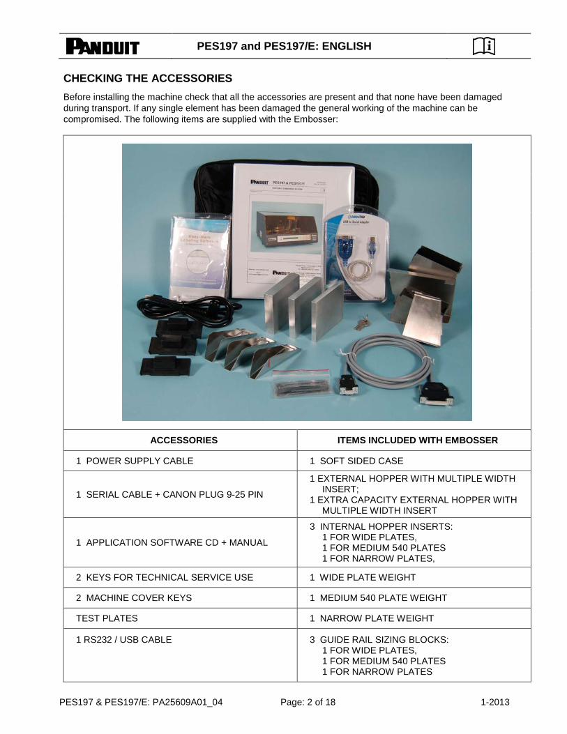
CHECKING THE ACCESSORIES
Before installing the machine check that all the accessories are present and that none have been damaged during transport. If any single element has been damaged the general working of the machine can be compromised. The following items are supplied with the Embosser:
ACCESSORIES ITEMS INCLUDED WITH EMBOSSER
1 POWER SUPPLY CABLE 1 SOFT SIDED CASE
1 SERIAL CABLE + CANON PLUG 9-25 PIN
1 EXTERNAL HOPPER WITH MULTIPLE WIDTH INSERT;
1 EXTRA CAPACITY EXTERNAL HOPPER WITH MULTIPLE WIDTH INSERT
1 APPLICATION SOFTWARE CD + MANUAL
3 INTERNAL HOPPER INSERTS: 1 FOR WIDE PLATES, 1 FOR MEDIUM 540 PLATES 1 FOR NARROW PLATES,
2 KEYS FOR TECHNICAL SERVICE USE 1 WIDE PLATE WEIGHT
2 MACHINE COVER KEYS 1 MEDIUM 540 PLATE WEIGHT
TEST PLATES 1 NARROW PLATE WEIGHT
1 RS232 / USB CABLE 3 GUIDE RAIL SIZING BLOCKS: 1 FOR WIDE PLATES, 1 FOR MEDIUM 540 PLATES 1 FOR NARROW PLATES

PES197 and PES197/E: ENGLISH
PES197 & PES197/E: PA25609A01_04 Page: 3 of 18 1-2013
CONNECTING CABLES
a. Connect the Serial Cable between the machine and the computer. b. Connect the AC cable to the rear input of the machine and to the proper AC source. Be sure to
verify the power required.
WARNING! To avoid electric shock the power plate protective grounding conductor must be connected to a ground circuit that conforms to the National Standard. WARNING! Remember to connect the serial cable to the machine while it is switched off to avoid damaging the circuits.
WARNINGS AND ADVICE DURING INSTALLATION
• The Identification Plate attached to the rear panel contains information about the serial number, the type of machine, the necessary power supply and maximum current.
• Before switching the machine on, be sure that all the cables have been connected correctly and that the local power supply corresponds to that stated on the plate. The plate layout is as follows:
Model : Machine model
Type : Embossing mode
Volt : Power Supply
Hz : Frequency supply
Imax : Maximum current (Amps)
SN : Serial Number
Manufactured on
Fuse rating
Serial socket for PC, 25 pin male
Not Used
Not Used
Identification Plate
PES197 supplied with UL Plate PES197/E supplied with CE Plate
Fuse
Main Switch
Key for service only AC Input

PES197 and PES197/E: ENGLISH
PES197 & PES197/E: PA25609A01_04 Page: 4 of 18 1-2013
Model : Machine model (EUR)
Type : Embossing mode
Volt : Power Supply
Hz : Frequency supply
Imax : Maximum current (Amps)
SN : Serial Number
Manufactured on
Fuse rating
Easy-Mark™ SOFTWARE INSTALLATION
Insert the Easy-Mark™ Installation CD in the CD ROM driver.
NOTE: If the CD ROM driver does not launch the Autorun.exe file automatically, from the START menu of Windows®, select Run and digit:
X:\Autorun.exe substituting the “X” with the letter of your CD unit
Read carefully the Readme.htm file, paying particular attention to the system requirements and follow the software installation instructions. When the installation is completed you will see the Easy-Mark™ icon on your desktop and the new “Easy-Mark” folder in the Start-Programs list.
INSTALL SOFTWARE FOR THE USB TO SERIAL ADAPTER (IF NEEDED) SYSTEM REQUIREMENTS
• Windows XP SP2 (recommended), Windows 2000 SP4, Vista, Windows 7 and Windows 8 • CablesToGo USB to Serial DB9 adapter (recommended) • Computer with available USB ports
INSTALL SOFTWARE FOR THE USB TO SERIAL ADAPTER
1. Insert the CD that came with the USB to Serial Adapter into the CD drive on the target computer. 2. If the auto start runs the installation go to step 6, if not continue. 3. Click on the My Computer icon, either on the desktop or click Start and then My Computer. 4. Double-click on the icon for the CD-ROM drive to display the files. 5. Find the Autorun.exe or Setup.exe file and double-click on it. 6. Select the option to install the USB to Serial Adapter you have with the Windows version you are
running. 7. Connect the cable to one of the USB ports and reboot if prompted to reboot.

PES197 and PES197/E: ENGLISH
PES197 & PES197/E: PA25609A01_04 Page: 5 of 18 1-2013
INTRODUCTION The Panduit PES197 (110V) and PES197/E (220V) is an automatic personalization system for metal marker plates. It is computer operated and runs off of Panduit Easy-Mark™ software. (e.g.: PC compatible). The Panduit PES197 machines stamp exclusively Panduit MMP350, MMP350H, MMP350W38 and MMP350HW54 Metal Marker Plates. The characters on the drum are as follows: A through Z, numbers 0 through 9, and special characters !, @, #, $, %, &, *, (, ), -, +, =, :, ", ,, ., /,’, and ?.
MMP350 18 CHARACTERS MAX.
per line 3 lines max
MMP350H 16 CHARACTERS MAX.
per line 3 lines max
MMP350W38 18 CHARACTERS MAX.
per line 1 line max
MMP350HW54 16 CHARACTERS MAX.
per line 2 lines max
(See accessories)
.02” plate -- special machine setup

PES197 and PES197/E: ENGLISH
PES197 & PES197/E: PA25609A01_04 Page: 6 of 18 1-2013
SYSTEM SPECIFICATIONS
Electrical Specification
PES197 & PES197/E
Power Supply 117V 60Hz PES197 230 V 50 Hz PES197/E
Current Absorption 4 A max Absorbed Power 250 W Fuse (5x20) T 4 A Logic 16 bit Microprocessor Backup Lithium Battery 3.6 V PC Interface RS 232 Asinc. Prog.
Baud Rate Programmable (supplied at 4800 Baud)
Working Noise Lower than 73 dB (A) Display LCD 2 line for 40 Chars. Keyboard 21 Programmable keys
Equipment Classification and Standard Reference
PES197 & PES197/E
Installation Category II IP Protection IP 20 Standard reference IEC EN 50081-1 IEC EN 50082-1 IEC EN 60950 ed. 4th IEC EN 60204-1 RoHS Certification 2011/65/EC
Working Condition
PES197 & PES197/E Listings in ( ) are metric.
Operating Temperature
+50° – +95° F (+10° ÷ +35° C)
Relative Humidity 20% – 85% Storing Temperature
+32° – +122° F (0 ÷ +50° C)
Dimensions and Weight
PES197 & PES197/E Listings in ( ) are metric.
Height 11.5” (292 mm) Width 21” (534 mm) Depth 19” (483 mm) Weight 95 lbs. (43 Kg)
Production Capacity
PES197 & PES197/E
Loading Hopper Capacity Capacity 200 Plates
Unloading Hopper Capacity Capacity 100 Plates
Plate Production Rate
90 Plates per hour, 20 Character Plate
PES197 and PES197/E: ENGLISH
PES197 & PES197/E: PA25609A01_04 Page: 7 of 18 1-2013
Safety Regulations and Operating Precautions
• The machine should work in a closed room protected from dust and excessive humidity. The machine should be positioned in such a way that its distance from the walls, doors, windows, other machines or working positions guarantees immediate access in case of emergency, maintenance or repairs.
• Do not install this Machine in the neighborhood of other Operating Machines which produce dust since dust can deposit itself inside the machine and cause damage to the internal electrical parts
• The Machine is furnished with special safety guards which protect the operator from coming into contact with the mechanical and electrical parts inside the machine. Only those persons who are specialized in repairs and maintenance and who have been authorized should have access to the above mentioned parts. Simple general maintenance can be safely performed by the operator so long as the machine has been stopped and the electrical power supply has been disconnected.

PES197 and PES197/E: ENGLISH
PES197 & PES197/E: PA25609A01_04 Page: 8 of 18 1-2013
• The Machine has been made with fire resistant materials thus diminishing the risk of fire. Short circuit protection has been implemented so that the power supply is immediately isolated thus avoiding unwanted current absorption from the external power line.
• Do Not place liquids on the machine cover since it is not waterproof. It is particularly important to avoid high humidity conditions which would add to the wear and corrosion of the mechanical parts.
The machine has labels that indicate any danger areas. The meanings of these labels are explained below.
Panduit cannot be held responsible for the consequences of not abiding by these safety rules when using the machine.
Therefore, in the case of breakdown, please call for Technical Assistance.
UNDER NO CIRCUMSTANCES REMOVE OR MODIFY THE INTERNAL COMPONENTS.
DO NOT REMOVE SAFETY GUARD These safety guards should be removed only by specialized and authorized technical persons who take care to adopt all security measures to avoid any risk of danger and injury.
BE CAREFUL OF YOUR HANDS! RISK OF BEING CRUSHED OR STRUCK The machine in the wooden package weighs 145 lbs. (66 Kg) and the net weight is 95 lbs. (43 Kg); therefore all lifting should be done with two persons present.
DANGER! HIGH VOLTAGE Do not perform any maintenance work while the machine is connected to the power supply. To replace a fuse or do internal maintenance, disconnect the power supply.
ATTENTION! MOVING MACHINE COMPONENTS If any maintenance work has to be done the technician must disconnect the power supply and work on the machine only when it has been stopped.
ATTENTION! DANGER The machine when at work has several moving units. Do not work on the inside of the machine. Do not remove the cover or guards except for the front cover which is used to load the plates.
GROUNDED (EARTHED) CABLES This symbol indicates that all the connected cables have been grounded (earthed).

PES197 and PES197/E: ENGLISH
PES197 & PES197/E: PA25609A01_04 Page: 9 of 18 1-2013
MACHINE SETUP FOR PRODUCING PLATES
• Unlock cover with cover key and open machine cover. (The cover will “latch” into the open position.) ADJUSTING THE LOADING UNIT
Height Adjustment: Adjust both height adjustment bars by loosening bar adjustment knobs ½ turn. Insert guide rail sizing block. Position height adjustment bars against the back of the guide rail sizing block. Tighten bar adjustment knobs to lock in place. Remove guide rail sizing block. (See Figs. 1 and 2)
Figure 1
Guide Rail Sizing Blocks
3/8” (9.5 mm)
Or 1/2” (13.7 mm)
Or 3/4” (19 mm)

PES197 and PES197/E: ENGLISH
PES197 & PES197/E: PA25609A01_04 Page: 10 of 18 1-2013
Figure 2
Figure 3
• Insert plates for embossing in the loader on the right side of the machine.
• NOTE: The plates must be arranged in the loader with the Easy Feed humps facing up.
Bar Adjustment Knobs
Height Adjustment Bars

PES197 and PES197/E: ENGLISH
PES197 & PES197/E: PA25609A01_04 Page: 11 of 18 1-2013
HOPPER INSTALLATION
EXTERNAL HOPPER - NARROW TAG INSERT INTERNAL HOPPER - WIDE TAG INSERT
a. Install External Hopper (see photo). b. Install proper External and Internal hopper inserts to match marker plate height. (see photo). c. Place appropriate plate weight on top of stack. Close machine cover by unlatching lock
mechanism located in the left rear of inside cover. SWITCHING ON AND CONTROLLING THE DISPLAY
The machine can be switched on with the main switch (located in back of machine). NOTE: Prior to switching “on”, make sure cover is closed. The display will appear with the message as shown below:
E-00 PWR-ON STAND-BY STATUS – PRESS START
Press the PAUSE/START key on left side of the front panel beside the display. This activates a general reset which, when completed, will leave another message on the display to indicate the Ready state of the machine.
PANDUIT METAL EMBOSSER V.#.## READY
If the machine does not start, check that the power supply is correctly set and that the main fuse has not been shorted. If error message appears, please refer to the “Error Messages and Problem Solving” section.
NOTE: If the display is turned on but nothing appears on the screen, switch the machine off and call for Technical Assistance. (see Regional Contact Information on Page 18)
The machine is now ready to run.

PES197 and PES197/E: ENGLISH
PES197 & PES197/E: PA25609A01_04 Page: 12 of 18 1-2013
Open Panduit Easy-Mark™ software.
Start Easy-Mark™ with a double click on the Easy-Mark™ icon present on the desktop. Insert the Password when requested by Login. Password is located on the CD. Click OK to start the first work session with Easy-Mark™.
a. Click FORMAT and select. b. In “Quick Find” box, type in the plate number you are going to emboss.
(MMP350, MMP350H, MMP350W38 or MMP350HW54) c. Type desired information onto marker plate. d. Press PRINT. Follow software prompts. e. Select communication port number (check the communication port number by going to the Windows
Device Manager). PRODUCTION - HOPPER
The production cycle finishes with the unloading of the plate on the left of the Embosser. If the cycle is error free, the Embosser returns to the initial READY STATE. If errors have occurred during the cycle, the machine will signal the error code on the display and will still unload the plate before stopping; the incorrect plate must be removed manually. Please refer to the section on “Error Messages and Problem Solving” for a description of the errors that can arise. CONSOLE
The console of the PES197 and PES197/E has two units: a front display and a membrane keypad.
The following list describes the structure of the front control panel: • An LCD display (2 rows with 40 characters per row), which is used to indicate the operating
status of the machine. • A PAUSE/START key • A FEED key • A red colored LED (top) to signal any error • A green colored LED (bottom) to signal that the machine is switched on
The following list describes the structure of the Keyboard:
• 10 numeric keys (0 – 9) • 6 function keys which enable the diagnostic functions of the machine
• 4 direction keys ( • ’ ‘ “ ) for moving the cursor in the desired direction • 1 ENTER key which is used to confirm the commands

PES197 and PES197/E: ENGLISH
PES197 & PES197/E: PA25609A01_04 Page: 13 of 18 1-2013
KEYBOARD DESCRIPTION
The following list describes the 6 function keys and their actions:
SETUP: This key is used to access the programming menu or other internal functions of the machine. A Password enables this command.
CARD TEST: This key enables the production of test plates with a pre-determined format. It is done without the aid of the computer. Select desired test below; then press ENTER to produce the plate.
The CARD TESTS for this machine are as follows: NOTE: Test plates must be run on either MMP350 or MMP350H plates.
CARD TEST 0 – Embosses all the characters in the drum. It will use three plates to do this since the plates are small and only so many characters fit on each plate.
CARD TEST 1 – Embosses an “L” in each corner of the plate.
CARD TEST 5 – Will emboss the Mechanical Parameters from the SETUP FILE using two plates.
CARD TEST 6 – Embosses Letters on the plate.
CARD TEST 10 – A drum test embossing characters on two sides of the drum, going back and forth.
CARD TEST 11 – Embosses the numbers in the drum.
CARD TEST 14 – Will load and pick the plate, then unload the plate. No embossing.
ABORT: If this key is pressed the current operating cycle will be halted and the plate will be unloaded. DUP: If this key is pressed during a READY state and it is followed by ENTER, the machine will repeat the last processed plate.
PAUSE: If this key is pressed the current operating cycle is blocked. Press START to continue. START: Clears any error condition which may have occurred during the current operating cycle. A corresponding error message will be displayed on the LCD.
FEED: This key permits the operator to repeat the last plate should there be an error during the production phase. Pressing this key will complete a paused cycle.

PES197 and PES197/E: ENGLISH
PES197 & PES197/E: PA25609A01_04 Page: 14 of 18 1-2013
EMB. MODE: This key selects the operational mode of the embossing cycle. It is used for tests and there are 8 choices based on the combinations of the following 3 modes:
CONTINUOUS: Repeats the last processed plate continuously
WITHOUT PLATE: Runs the operating cycle without controlling for the presence of a plate
PAUSE: Executes each operation in response to the user input. The key to activate each movement is START
ATTENTION! If there are errors on the plate (X motor Error, & Motor Error, etc.) there are two possible solutions:
Pressing PAUSE/START clears the error condition without reproducing the plate.
Pressing FEED activates the plate duplication procedure.
DISPLAYING THE COUNTERS OF THE PRODUCED PLATES
The statistical data of the production is available in the partial and total counters. The latter cannot be modified. The value indicates the total number of operating cycles with and without error. To start the counters, run the following command sequence from machine console:
SETUP
The following is displayed: SETUP EMBOSSER
PASSWORD ? No action required; continue with command sequence:
• 1 ENTER
The following is displayed: METAL MARKER PLATEXXX PLUS V.Y.YY
CNT = 0000000001 TOTAL = 0000000001 CNT: is the partial counter for the operator TOTAL: is the total counter.
The counters are removed from the display using the same keystrokes. To reset counters; run the following command sequence from machine console:
SETUP
The following is displayed: SETUP EMBOSSER
PASSWORD ? No action required; continue with command sequence:
• 0 ENTER The counter is Reset.

PES197 and PES197/E: ENGLISH
PES197 & PES197/E: PA25609A01_04 Page: 15 of 18 1-2013
ERROR MESSAGES In case of breakdown or operator error, the machine will show what caused the machine cycle interruption on the display and on the monitor. Contact technical support if code is not in table
ERROR MESSAGE CAUSE SOLUTION
E-00 PWR-ON STAND BY STATUS-PRESS START
MACHINE EXPECTING THE RESET COMMAND
PRESS START, ANY OPEN EASYMARK PRINT JOB MUST BE CANCELLED AND RESTARTED
E-01 OUT OF CARDS-PRESS START/FEED THE LOADER IS EMPTY PLATES LOADED UPSIDE-DOWN
FILL THE LOADER LOAD PLATES WITH EASY FEED HUMPS FACING UP
E-02 CARD MISFEED-PRESS START/FEED
THE CLAMP HAS NOT PICKED UP THE PLATE BRIGHT LIGHT ABOVE EMBOSSER
CHECK FOR ANY DAMAGED AND/OR MISFED PLATES AND REMOVE TURN OFF LIGHT OR SHADE THE SENSOR
E-03 PUNCH MOTOR ERROR-CALL SERVICE EMBOSSING MOTOR BLOCKED CALL TECHNICAL SUPPORT
E-04 EMB. WHL ERR-CHECK CARD/PRESS START DRUM BLOCKED
CONTROLS THE PUNCHES, IF PROBLEM PERSISTS CALL TECHNICAL SUPPORT
E-05 X MOT. ERR-CHECK CARD/PRESS START
PROBLEM ON THE CLAMP’S TROLLEY
CLEAN AND OIL THE TROLLEY GUIDE AND CHECK THAT IT MOVES FREELY
E-06 Y MOT. ERR-CHECK CARD/PRESS START PROBLEM ON CLAMP
CLEAN AND OIL THE TROLLEY GUIDE AND CHECK THAT IT MOVES FREELY
E-10 PAUSE EMBOSSING-PRESS START THE FRONT COVER HAS BEEN OPENED
CLOSE THE COVER AND PUSH START
E-13 PUSHER MOTOR ERROR DIRTY SENSOR CLEAN SENSOR, CALL TECHNICAL SUPPORT
E-50 DRUM WHEEL ERROR-PRESS START DRUM MOTOR BLOCKED CHECK THE PUNCHES AND RETRY, IF PROBLEM PERSISTS CALL TECHNICAL SUPPORT

PES197 and PES197/E: ENGLISH
PES197 & PES197/E: PA25609A01_04 Page: 16 of 18 1-2013
TROUBLE SHOOTING
Contact technical support for assistance with the following adjustments: Gate Adjustment: Factory set to .014 ± .002”. (Stainless Steel) Factory set to .016 ± .002”. (Aluminum)
Marker Plate Hold Down Adjustment Factory set to .015 ± .003”. (Stainless Steel and Aluminum)
OPTIONAL ACCESSORIES
1. Embosser for .020” thick metal marker plates: Consult factory
GENERAL MAINTENANCE The operator should make a habit of doing general maintenance on the Embosser so as to ensure a correct and long lasting functioning of the system.
ATTENTION! DANGER The machine when at work has several moving units. Do not work on the inside of the machine. Do not remove the cover or guards except for the front cover which is used to load the plates. The maintenance should be done with the machine switched off.
Routine maintenance as listed below must be followed:
• After the first 8 hours of embossing work, switch off the machine and remove the power supply cable. Lift up the front cover and proceed as follows:
ATTENTION! DANGER IMPORTANT: Do not remove the cover and the guards that are present inside the embossing machine.

PES197 and PES197/E: ENGLISH
PES197 & PES197/E: PA25609A01_04 Page: 17 of 18 1-2013
OILING THE TROLLEY TRACK AND CLAMP GUIDE
• Apply light oil at the clamp’s trolley track (X travel guide – top and bottom), moving the trolley by hand back and forth to assure an even distribution of the oil and to control the fluidity of movement.
• Apply light oil at the clamp guide (Y travel guide – both sides), moving the clamp by hand back and forth to assure an even distribution of the oil and to control the fluidity of movement.
Lubricate Every 6 months, or as needed Every year Lubricant
X & Y Guides Yes 3-in-One Oil ® Contact Panduit Tool Service for the maintenance items listed below:
Carriage Bearing Yes High temperature red lithium grease
Dies Yes High temperature red lithium grease
Punch Cams Yes High temperature red lithium grease
Input Hopper pushers Yes 3-in-One Oil ®
1. Heavy users and dusty environments need to be cleaned and lubricated more often based on
contamination. 2. X and Y guides: Clean grooves then use 3-in-One® oil.
Run “Card Test 14” on continuous to spread lubricant. When the general maintenance is finished switch the embosser on and make sure that the front cover does block all operations. If this is not the case, call for Technical Assistance, as one or more safety devices could be damaged.

PES197 and PES197/E: ENGLISH
PES197 & PES197/E: PA25609A01_04 Page: 18 of 18 1-2013
CONTACT INFORMATION • For Technical Support:
Panduit USA – Corporate Headquarters, Tinley Park, IL USA Tel: 888-506-5400, ext. 83255 Website: www.panduit.com • E-mail: [email protected] Panduit Latino America – Guadalajara, Jalisco, Mexico Latino America Tel.: 52 (333) 666 2501 • Fax.: 52 (333) 666 2510 Website: www.panduit.com • E-mail: [email protected] Panduit Europe – EMEA Service Center Almelo, Netherlands Tel: +31 546-580-452 • Fax: +31 546-580-441 Website: www.panduit.com/emea E-mail: [email protected] Panduit Australia – Head Office, Melbourne Dandenong, VIC Aus. Tel: 1-800-PANDUIT / 1-800-726-384 • Fax: 1-800-637-889 Email: [email protected] Panduit United Arab Emmerites Dubai Internet City, Dubai Tel: +971 4 3625435 /6 • Fax: +971 4 3908830 E-mail: [email protected] Panduit China – Beijing Xuanwumen Xidajie Xicheng District Beijing, China Tel: 8610 6641 0371 • Fax: 8610 6641 0375 Toll Free Customer Service - North China: 10800 6500 211 • South China: 10800 2650 211 E-mail: [email protected] Panduit Singapore – Sales Office Singapore, Republic of Singapore Tel: 65 6379 6700 • Fax: 65 6379 6759 E-mail: [email protected] Panduit Japan – Tokyo Headquarters Shinagawa NSS Building, 3rd Floor 2-13-31 Konan, Minato-ku, Tokyo, Japan 108-0075 Tel: 03-6863-6000 • Fax: 03-6863-6100 Website: http://eeg.panduit.co.jp • Email: [email protected]