p4a instruction manual - store.gegridsolutions.com for cts available from multilin are shown in ......
TRANSCRIPT

MOTOR PROTECTION RELAYINSTRUCTION MANUAL

INSTRUCTION MANUAL
MOTOR PROTECTION RELAYPATENTS U.S. 4,241,336 4,224,651
CANADA 1,130,383
COPYRIGHT 1982, 1986, 1988 MULTILINALL RIGHTS RESERVED
215 Anderson Ave., PO Box 2700Markham, Ontario, Canada L3P 4C7Tel: (905) 294-6222 Fax: (905) 294-8512
TABLE OF CONTENTS
1. INTRODUCTION1.1 Motor Protection Requirements ................................................... 11.2 Protect 4A Features .....................................................................31.3 Typical Applications .....................................................................41.4 Order Code ..................................................................................51.5 Technical Specifications ..............................................................6
2. INSTALLATION2.1 Physical Dimensions ...................................................................72.2 Mounting ...................................................................................... 92.3 External Wiring .......................................................................... 102.4 Control Power ............................................................................ 112.5 Trip Contacts ............................................................................. 122.6 Thermistor Input ........................................................................ 122.7 Programmable Controller Output .............................................. 142.8 Tamper Proof Cover .................................................................. 142.9 Field Options — Auto Reset .................................................... 15
Mechanical Jam ............................................ 16Ground Fault Indication Only ........................ 16Single Phase Defeat ..................................... 17Factory Service ............................................. 17
2.10 Environment .............................................................................. 17
3. SETUP AND USE3.1 Control and Indicators ............................................................... 193.2 Full Load Control ....................................................................... 203.3 Stall Time Control ...................................................................... 233.4 Ground Fault (Earth Leakage) Level Control ............................ 243.5 Ground Fault (Earth Leakage) Time Delay Control ................... 253.6 Single Phase Detection ............................................................. 263.7 Thermistor Trip Detection .......................................................... 273.8 Reset/Test Button ...................................................................... 283.9 Motor Amps Output .................................................................... 293.10 Fault Diagnosis .......................................................................... 30
4. RELAY TESTING4.1 Commissioning Tests ................................................................. 314.2 Overloads .................................................................................. 334.3 Single Phasing ........................................................................... 344.4 Ground Fault/Earth Leakage ..................................................... 354.5 Thermistor ................................................................................. 374.6 4-20 mA Output ......................................................................... 384.7 Routine Maintenance Verification .............................................. 394.8 Problem Troubleshooting ........................................................... 40
5. THEORY OF OPERATION5.1 Hardware ................................................................................... 425.2 Firmware .................................................................................... 45

1
1. INTRODUCTION
1.1 MOTOR PROTECTION REQUIREMENTS
Three phase AC motors have become the workhorse of mod-ern industry. Although motors are generally reliable devices,many different causes ranging from abnormal conditions to op-erator abuse can result in premature failure. Newer motors alsotend to be designed much closer to the normal operation limitsallowing less margin for abuse.
Sophisticated electronic relays are now normally used on largehigh voltage motors to protect against a wide range of possiblefault conditions. High cost has precluded the use of these re-lays on less expensive motors. In these applications, a simplethermal overload is usually used. While inexpensive, these de-vices only give limited protection under one type of fault condi-tion — overloads.
The PROTECT 4A relay is designed to provide protectionagainst the four main causes of motor failure: overloads, singlephasing, ground faults (earth leakage) and overheating (ther-mistor sensing). The Protect 4A relay is economical enough inprice that it can be used with low and medium voltage motors,bridging the gap between expensive, sophisticated relays andeconomical thermal overloads which are of limited effectiveness.While no relay can prevent normal wear on the motor, the Pro-tect 4A has been optimized to give maximum motor life withoutunnecessary production shutdown from overprotection. Controlsare simple and self explanatory for ease of use.
Current sensing is achieved through the use of separate phaseand ground fault CTs connected directly to the PROTECT 4Arelay. Three 5 amp or 1 amp secondary CTs are used to sensemotor phase currents. The three phase current wires passthrough the window of a 2000:1 CT for ground fault sensing.

2
FIGURE1-1 PROTECT 4A TYPICAL SYSTEM CONNECTION

3
1.2 PROTECT 4A FEATURES
A microcomputer housed in a rugged, industrial package al-lows the Protect 4A to provide accurate, economical protectionin a unit that will outlast the life of the motor. Since many newfactories are using programmable controllers as automation in-creases, a 4-20mA output of motor current is also provided elimi-nating the need for an additional transducer. This output givesa direct reading of motor current.
Fault diagnosis after a trip is displayed on front panel indica-tors. This will allow operators and electricians to rapidly isolateand correct problems. It is possible to verify correct operationof an installed Protect 4A relay to ensure that the motor protec-tion is functioning properly.
One Protect 4A relay is required per motor. Phase and groundfault currents are monitored through current transformers so thatmotors of any line voltage can be protected. The relay is usedas a pilot device to cause a contactor or breaker to open underfault conditions; that is, it does not carry the primary motor cur-rent. Figure 1-1 shows how the Protect 4A is connected into asystem for complete motor protection.
TABLE 1-1 PROTECT 4A FEATURES
FEATURES
• Fault Diagnosis• 4–20mA Output of Motor
Current• Overload Status Indicator• Economical• Compact — Plug In• Universal Models
Simplify Spares
PROTECTION
• Overloads(8 Time Curves)
• Locked Rotor/Stall• Mechanical Jam• Multiple Starts• Single Phasing• Ground Fault/Earth
Leakage (Trip or indica-tion only)
• Overheating (ThermistorSensing)

4
1.3 TYPICAL APPLICATIONS
Versatile features make the Protect 4A an ideal choice in a widerange of motor applications. It should be considered for theseand other typical uses:
1) Basic protection on low and medium voltage motors. Thelowest horsepower selected for protection in an installa-tion will depend on frequency of motor failure.
2) Protection of motors and equipment from operator abuse
3) Personnel safety from shock hazard using sensitive groundfault settings to detect winding shor ts or leakage currentfrom moisture in mines.
4) Fault indication of ground fault without shutdown to warnthat corrective maintenance is required.
5) Mechanical protection of gears, pumps, fans, saw mills, cut-ters and compressors against mechanical jam.
6) Simplified spare parts stocking using one universal modelto cover all motor sizes and settings.
7) Output of motor current suitable for programmable controllerinterface (4–20mA).
The motor phase currents are sensed by 3 conventional 1 ampor 5 amp secondary current transformers (CTs). If ground faultsensing is required then a separate zero sequence ground faultCT, through which all 3 phase conductors pass, is required. ThisCT is available in 2 sizes: HGF-3 (3½" diameter window) or HGF-5 (5½" diameter window).
Note: Ground fault sensing only works on systems that are solidor resistance grounded. Ungrounded systems require an artifi-cial ground, through the use of a zigzig transformer, for groundfault sensing to work.

5
PHASE SENSING CURRENT TRANSFORMERS
Any standard 5 amp secondary 5 VA or greater CT can beused. 3 phase CTs per PROTECT 4A are required. 1 ampCT operation available on special order.PART NO. DESCRIPTIONCT-100:5 100:5CT-150:5 150:5CT-200:5 200:5CT-250:5 250:5CT-300:5 300:5CT-500:5 500:5CT-1000:5 1000:5
1.4 ORDER CODE
TABLE 1-2 RELAY ORDER CODE
RELAY
PROTECT 4A — 120
PART NO. DESCRIPTION
PROTECT 4A Standard relay
— 120 120 VAC control voltage— 240 240 VAC control voltage
GROUND FAULT CURRENT TRANSFORMERS
1 required for ground fault sensing:
PART NO. DESCRIPTION
HGF3 3½" Window 2000:1HGF5 5½" Window 2000:1

6
1.5 TECHNICAL SPECIFICATIONS
TABLE 1-3 TECHNICAL SPECIFICA TIONS
FULL LOAD CURRENT50-100% PHASE CT RATINGINPUT: 0-8 TIMES MAXIMUM RANGE
CURRENTFREQUENCY: 48-62 Hz, 3 PHASE SINUSOIDMAXIMUM INPUT: 8 TIMES FULL LOAD 25 SECONDS
12 TIMES FULL LOAD 2 SECONDS
FULL LOAD CONTROL — AMPSRANGE: 50-100% PHASE CT RATINGCALIBRATED VALUE:3 PHASE SINEWAVE-RMS
EQUIVALENTPICKUP ACCURACY: ±5% FULL SCALEOVERLOAD TIMES: ±10% CURVE VALUEMECHANICAL JAM: ACTIVATED AT 3 TIMES FULL LOAD
SETTING IF ENABLED.NOMINAL DELAY — 1 SECOND
SINGLE PHASEACTIVATION: SEVERE UNBALANCE/SINGLE
PHASE DEFEATED IF MOTORAVERAGE CURRENT < 40% FULLLOAD SETTING
TRIP DELAY: 5 SECONDS ±2 SECONDS
THERMISTOR INPUTHOT TRIPRESISTANCE: 2800-3300 OHMSCOLD RESETRESISTANCE: 250 OHMS MAXTRIP DELAY: 3 SECONDS ±1 SECOND
THERMISTOR MEMORY MODELACTIVE: MOTOR RUNNING/STOPPED WITH
CONTROL POWERCLEAR: POWER ON OR RESET AFTER TRIPCOOL RATE: 5 MINUTES TO CLEAR MEMORY
@10 SEC STALL SETTINGRESET: NO LOCKOUT ON TRIP
GROUND FAULT/EARTH LEAKAGETRIP LEVEL: 1-10A ±15% PRIMARY CURRENT
FULL SCALE(0.5A MAX WITH CONTROL FULLYANTI-CLOCKWISE)
TRIP DELAY: TIMES AT < 25% PICKUPTHRESHOLD30ms 7-30ms TYPICAL 30ms MAX50, 100ms: ±15ms200, 300, 500, 750,100ms: ±15%
MOTOR AMPS OUTPUTOUTPUT CURRENCY: 4 mA = 0 AMPS
20 mA = PHASE CT RATINGACCURACY: LINEAR ±5% FULL SCALEMAXIMUM LOAD RESISTANCE: 350 OHMSSATURATION OUTPUT: 30 mA MAX
OUTPUT CONTACTSTYPE: SINGLE FORM C NO/NC
SILVER CADMIUM OXIDERATINGS: STANDARD PILOT DUTY
120/240 VAC 10 AMPS@ 80% P.F.360VA28 VDC 10 AMPS
CONTROL POWER120VAC INPUT RANGE: 85-140 VAC240VAC INPUT RANGE: 170-280 VACFREQUENCY: 48-62 HzPOWER: 5VA
PHYSICALSHIPSHIPSHIPSHIPSHIP CARCARCARCARCARTONTONTONTONTON
PRODUCTPRODUCTPRODUCTPRODUCTPRODUCT WEIGHTWEIGHTWEIGHTWEIGHTWEIGHT DIMENSIONSDIMENSIONSDIMENSIONSDIMENSIONSDIMENSIONS
PROTECT 4A4 lbs 5¼" × 5¼" × 7½"
8.8 kg 133mm × 133mm × 191mm
HGF3 2.2 lbs 2½" × 6½" × 6½"1 kg 64mm × 165mm × 165mm
HGF5 3.8 lbs 3" × 8" × 9"1.5 kg 76mm × 204mm × 228mm
ENVIRONMENTTEMPERATURE RANGE–10°C — +60°C
CERTIFICATION: CSA

7
2. INSTALLATION
2.1 PHYSICAL DIMENSIONS
Dimensions of the Protect 4A relay and mounting componentsare shown in fig. 2-1. Both the clear cover and the terminal boardare detachable from the relay. The case is made of rugged plasticwith a clear cover for viewing indicators and control settings.
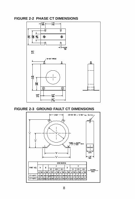
Phase CTs with 1 amp or 5 amp secondaries should be used.These can be standard CTs which are user supplied. Dimen-sions for CTs available from Multilin are shown in figure 2.2. Ifzero sequence ground fault detection is required, the appropri-ate ground fault CT shown in figure 2-3 must be installed.
FIGURE 2-1 RELAY DIMENSIONS
REAR VIEW
8
FIGURE 2-2 PHASE CT DIMENSIONS
FIGURE 2-3 GROUND FAULT CT DIMENSIONS
9
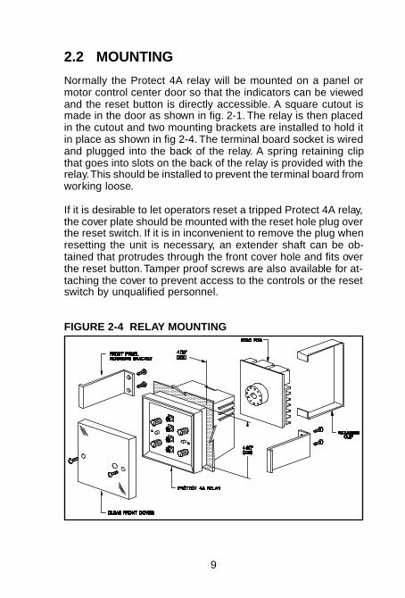
2.2 MOUNTING
Normally the Protect 4A relay will be mounted on a panel ormotor control center door so that the indicators can be viewedand the reset button is directly accessible. A square cutout ismade in the door as shown in fig. 2-1. The relay is then placedin the cutout and two mounting brackets are installed to hold itin place as shown in fig 2-4. The terminal board socket is wiredand plugged into the back of the relay. A spring retaining clipthat goes into slots on the back of the relay is provided with therelay. This should be installed to prevent the terminal board fromworking loose.
If it is desirable to let operators reset a tripped Protect 4A relay,the cover plate should be mounted with the reset hole plug overthe reset switch. If it is in inconvenient to remove the plug whenresetting the unit is necessary, an extender shaft can be ob-tained that protrudes through the front cover hole and fits overthe reset button. Tamper proof screws are also available for at-taching the cover to prevent access to the controls or the resetswitch by unqualified personnel.
FIGURE 2-4 RELAY MOUNTING

10
2.3 EXTERNAL WIRING
A typical wiring diagram for the Protect 4A relay is shown infigure 2-5. Connections are made to the terminal board pro-vided which is then plugged onto the Protect 4A relay. Protect4A relays are interchangeable and can be quickly replaced bya standard spare unit regardless of the motor current range.
Separate phase and ground fault CTs are wired directly to theback of the Protect 4A. It is recommended that the ground faultCT wires be twisted together to minimize noise pickup.
FIGURE 2-5 TYPICAL WIRING DIAGRAM
11
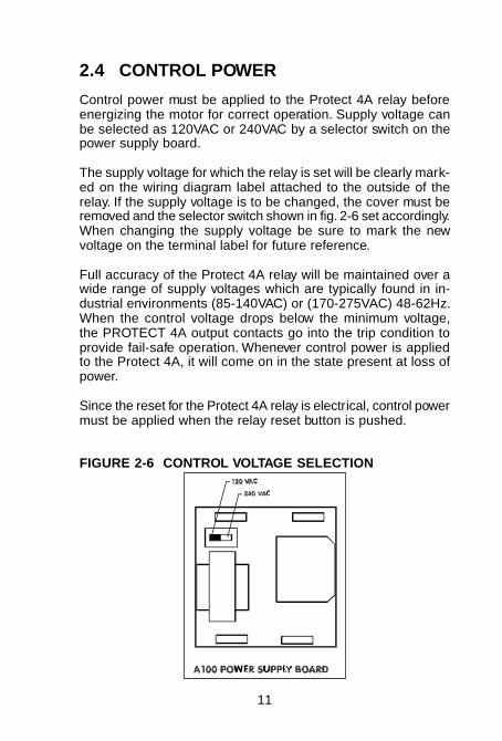
2.4 CONTROL POWER
Control power must be applied to the Protect 4A relay beforeenergizing the motor for correct operation. Supply voltage canbe selected as 120VAC or 240VAC by a selector switch on thepower supply board.
The supply voltage for which the relay is set will be clearly mark-ed on the wiring diagram label attached to the outside of therelay. If the supply voltage is to be changed, the cover must beremoved and the selector switch shown in fig. 2-6 set accordingly.When changing the supply voltage be sure to mark the newvoltage on the terminal label for future reference.
Full accuracy of the Protect 4A relay will be maintained over awide range of supply voltages which are typically found in in-dustrial environments (85-140VAC) or (170-275VAC) 48-62Hz.When the control voltage drops below the minimum voltage,the PROTECT 4A output contacts go into the trip condition toprovide fail-safe operation. Whenever control power is appliedto the Protect 4A, it will come on in the state present at loss ofpower.
Since the reset for the Protect 4A relay is electrical, control powermust be applied when the relay reset button is pushed.
FIGURE 2-6 CONTROL VOLTAGE SELECTION

12
2.5 TRIP CONTACTS
One set of form C normally open/normally closed contacts areprovided for switching up to 240VAC, 10 amps, 360VA whichshould be adequate for most loads. Silver cadmium oxide con-tacts are provided because of their ability to withstand high in-rush inductive loads. Connection of the trip contacts to the motorcontactor or breaker is shown in the typical wiring diagram fig-ure 2-5.
When the relay is ready for motor starting, the contacts for termi-nals 1, 2, 3 will be as shown in figure 2-5. When the relay trips,or if control power is lost, the contacts will change to the oppo-site condition. However, if this change occurred from lost con-trol power, the main relay will return to its normal operating statewhen power is re-applied, without having to reset the relay.
The output contacts can be returned to the untripped state bypressing the reset button or by selecting the auto reset option(section 2.9.1.).
2.6 THERMISTOR INPUT
In order to use the thermistor sensing feature the motor beingprotected must have a suitable thermistor sensor embedded inthe stator winding. This is normally fitted when the motor is builtor rewound although it may be possible to retrofit a thermistorinto the end turns of some motors. Thermistors exhibit a non-linear characteristic and the Protect 4A is designed to match acharacteristic similar to that shown in figure 2-7. The actual triptemperature of the thermistor is specified when it is ordered.Consult the factory for recommended thermistor types that willwork with the Protect 4A relay.
If three thermistors are installed in the motor connect them inseries as shown in figure 2-8. When combining several ther-mistors in series, care should be taken to ensure that the maxi-mum cold resistance including wiring resistance does notexceed the trip temperature resistance. If any thermistor over-heats in this configuration the relay will trip. Should no thermis-tor be installed in the motor it is not necessary to make any

13
connection to terminals 5 and 6. A no sensor detector will pre-vent the relay from tripping. Alternately, a jumper can be placedacross these two terminals. The Protect 4A relay is not suit-able for use with RTDs (resistance temperature detectors).
If no thermistor is used, put a jumper between terminals 5 and6 to prevent nuisance tripping from noise. Shielded wire shouldbe used for the thermistor input especially if the wiring is nearhigh current conductors or if the motor is remotely situated. Max-imum shield effectiveness is obtained if the shield is groundedat one end only.
FIGURE 2-7 THERMISTOR CHARACTERISTIC
FIGURE 2-8 THERMISTOR CONNECTION

14
2.7 PROGRAMMABLE CONTROLLER OUT-PUT
In many installations an output of motor current into a program-mable controller is desirable. Terminals 4 (+ VE) and 5 (-VE)provide a DC output of 4-20mA proportional to motor current.The 20mA output is obtained at the rated CT ratio. For exam-ple, if a 600:5 CT is used, at 600 Amps the output would be20mA. The output saturates below 30mA during overloads toprevent damage to the programmable control.
2.8 TAMPER PROOF COVER
If limited access to the Protect 4A controls is desired to preventsettings from being altered by operators, tamper proof screwsand a special installation tool can be ordered. The normal coverscrews are replaced with these special screws so that the covercannot be removed without the tool. The cover can also be ro-tated 180 degrees and a plug placed over the reset button hole.This prevents access to the reset button so that only qualifiedpersonnel can reset the relay once it has tripped.
2.9 FIELD OPTIONS
It is possible to change some features on the relay in the fieldfor specific applications. Refer to the internal switch setting loca-tion diagram fig. 2.9 to set the field options.
15
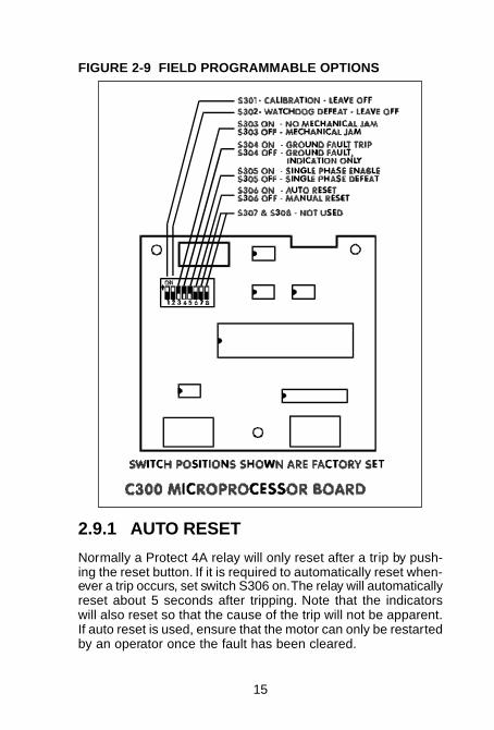
FIGURE 2-9 FIELD PROGRAMMABLE OPTIONS
2.9.1 AUTO RESET
Normally a Protect 4A relay will only reset after a trip by push-ing the reset button. If it is required to automatically reset when-ever a trip occurs, set switch S306 on. The relay will automaticallyreset about 5 seconds after tripping. Note that the indicatorswill also reset so that the cause of the trip will not be apparent.If auto reset is used, ensure that the motor can only be restartedby an operator once the fault has been cleared.

16
2.9.2 MECHANICAL JAM
Overloads will normally cause a trip according to the overloadcurves of fig. 3-2. In some situations it may be desirable to pro-tect associated mechanical equipment against a jam while runn-ing. Setting switch S303 off will cause the relay to trip wheneverthe current rises above 3 times the FULL LOAD—AMPS con-trol setting for one second while the motor is running
The Protect 4A automatically defeats mechanical jam duringthe high starting inrush current but enables this option (if switchS303 is off) as soon as the inrush current drops below the FULLLOAD AMPS setting. This feature is especially useful in appli-cations such as pumps and fans where overloads are not partof normal operation. Mechanical jam will activate the overloadindicator.
2.9.3 GROUND FAULT INDICATION ONLY
In some resistance grounded systems a single ground faultdetector is used to monitor a complete bus feeding numerousmotors. If one of the motors develops a ground fault, an alarmcondition is registered on the central ground fault monitor butthe motors may be allowed to continue running to prevent aproduction shut down. This is possible since the ground faultcurrent is resistance limited, however the faulty motor shouldbe repaired as soon as possible because a second ground faulton another phase could cause a phase to phase short circuitresulting in extensive damage. If the motors don’t have indi-vidual ground fault protection, the whole bus must be sched-uled for a convenient shutdown and each motor checked untilthe faulty one is found.
A ground fault above the trip settings will normally cause theProtect 4A to trip with a ground fault indication. Setting switchS304 off will cause the ground fault indicator to activate but willinhibit a trip due to a ground fault. If each motor is equippedwith a Protect 4A and this feature is selected, when the centralmonitor registers a ground fault, it is only necessary to look ateach Protect 4A to locate the faulty motor. The defective motorcan then be shut down and repaired when convenient withoutshutting down the rest of the bus and testing every motor.

17
This scheme is not suitable for solidly grounded systems sinceany motor which develops a ground fault should be shut downimmediately due to the high current that can flow.
Once the ground fault indicator is set it can only be reset bypressing the reset button. This makes it particularly useful fordetecting momentary ground faults due to initial insulation break-down and arcing or excessive moisture in mines,
2.9.4 SINGLE PHASE DEFEAT
Systems such as variable speed controllers may produce non-sinusoidal waveforms that may cause nuisance tripping of thesingle phase detection. If this is a problem, the single phaseprotection may be defeated by setting switch S305 off.
2.9.5 FACTORY SERVICE
Switches S301/S302 are used for factory calibration. Theyshould be left off for correct operation.
2.10 ENVIRONMENT
Precision components and rugged industrial packaging are us-ed to ensure that Protect 4A relays will perform accurately andreliably over a wide range of conditions typical of industrial en-vironments around the world. Some of the features incorporatedinto the Protect 4A design to ensure trouble free operation anduseful life longer than the motor being protected are listed intable 2-1.
TABLE 2-1 PROTECT 4A ENVIRONMENTAL FEATURES
• Transient protection/filtering on inputs and outputs• Crystal controlled time delays for accuracy with tem-
perature/aging• Precision IC voltage references for stable accuracy• Wide temperature range –10°C to +60°C
18
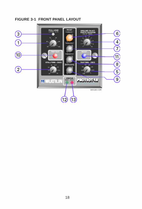
FIGURE 3-1 FRONT PANEL LAYOUT

19
3. SETUP AND USE
3.1 CONTROL AND INDICATORS
NO. NAME FUNCTION
1 FULL LOAD CONTROL Sets the maximum average RMS motorcurrent at which overload pickup occurs.Calibrated in % CT rated amps.
2 STALL TIME Selects one of eight overload time curvesbased on stall times at 6 times inrushcurrent.
3 OVERLOADINDICATOR
Flashing - motor current exceeds full loadsetting (overloads or starting).
4 GROUND FAULT(EARTH LEAKAGE)TIME DELAY CONTROL
Sets level of ground fault currentnecessary to cause a trip. Calibrated inamps.
5 GROUND FAULT(EARTH LEAKAGE)TIME DELAY CONTROL
Sets time ground fault current mustexceed level setting before a trip.Calibrated in seconds.
6 OVERLOADINDICATOR
Set whenever overload or mechanicaljam trip occurs.
7 UNBALANCEINDICATOR
Set whenever single phase trip occurs.
8 THERMISTORINDICATOR
Set when thermistor senses anovertemperature and relay trips.
9 GROUND FAULT/EARTH LEAKAGEINDICATOR
Set when ground fault trip or ground faultalarm occurs.
10 TEST TRIP Activates trip indicators (6-9) and the triprelay when pressed.
11 RESET Resets all fault indicators and trip relay.
12 READY INDICATOR Indicates the output contacts areuntripped ready for motor starting.
13 FAULT INDICATOR Indicates the output contacts are trippeddue to a fault condition. Motor cannot bestarted.

20
3.2 FULL LOAD CONTROL
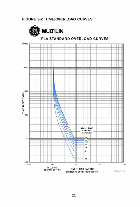
The full load control is calibrated in % of phase CT rated amps.It should be set to the maximum load rating of the motor beingprotected. For example, a setting of 75% with 100:5 phase CTscorresponds to a motor full load current of 75 amps. In thetime/overload curves of figures 3-2 the value of a multiple ofone full load is represented by the current set on this control.When the current exceeds the full load control setting, the over-load indicator light will flash to indicate an overload and therelay will begin to time the overload according to the time/over-load curves of fig. 3-2. If the condition persists the relay willeventually trip.
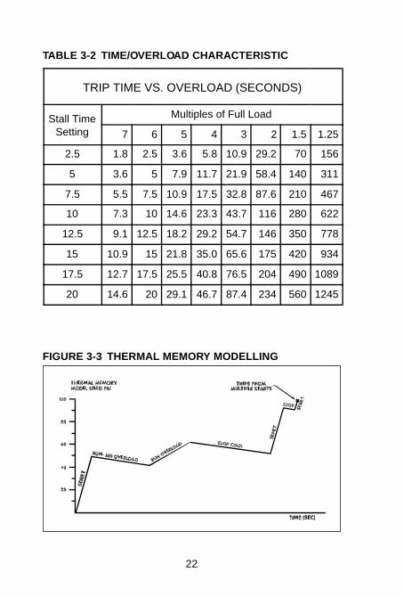
When the motor is in a normal run state the internal memorybegins to discharge to simulate motor cooling. Overload trip timewill be reduced by the cumulative effect of previous overloadsand starting inrush unless the motor has not been overloadedfor a period of time in which case the memory is empty to simu-late a cool motor.
Multiple start protection is provided by the memory which in-tegrates the heating effect of each start. If power is lost andreapplied or if the reset button is pressed after a trip, the memorywill be empty. Figures 3-3 shows how the thermal memory mod-elling operates for typical motor operation.
21
FIGURE 3-2 TIME/OVERLOAD CURVES
P4A STANDAR D OVERLOAD CURVES1 0 00 0 0
1 00 0 0
10 0 0
1 0 0
1 0
1 .0 00 . 1 0
OVERLOAD FACTOR(Multiples of full load control)
FUL L L OA DCO NTR OL S E TTI NG
TIM
E IN
SEC
ON
DS
1 0 1 0 0 1 0 0 0
930112A 1.CDR
1 .0 0
22
TABLE 3-2 TIME/OVERLOAD CHARACTERISTIC
TRIP TIME VS. OVERLOAD (SECONDS)
Stall TimeSetting
Multiples of Full Load
7 6 5 4 3 2 1.5 1.25
2.5 1.8 2.5 3.6 5.8 10.9 29.2 70 156
5 3.6 5 7.9 11.7 21.9 58.4 140 311
7.5 5.5 7.5 10.9 17.5 32.8 87.6 210 467
10 7.3 10 14.6 23.3 43.7 116 280 622
12.5 9.1 12.5 18.2 29.2 54.7 146 350 778
15 10.9 15 21.8 35.0 65.6 175 420 934
17.5 12.7 17.5 25.5 40.8 76.5 204 490 1089
20 14.6 20 29.1 46.7 87.4 234 560 1245
FIGURE 3-3 THERMAL MEMORY MODELLING

23
3.3 STALL TIME CONTROL
One of eight different time/overload curves can be selected bythe stall time control to closely match the thermal characteris-tics of the motor. If curve data is available from the motormanufacturer the next lowest curve from fig. 3-2 should be se-lected and the stall time control set accordingly.
Each of the curves represents an I2t characteristic of a motorhaving the specified stall time set by the control at an inrushcurrent of 6 times the motor full load rating which is fairly typi-cal. If no motor curve data is available, this control should beset to the next lowest stall time from that specified for the mo-tor. Thus for a motor with a rated stall time of 9 seconds at 6times full load, the STALL TIME control would be set to 7.5 sec-onds. If the stall time is specified at some other inrush current,the point can be plotted on the time/overload curves of fig. 3-2and the next lowest curve selected.
Table 3-2 lists the curve points in tabular form. Points for a se-lected curve can be plotted directly on curves for associatedequipment to facilitate a coordination study with systems thatuse the Protect 4 relay.

24
3.4 GROUND FAULT (EARTH LEAKAGE)LEVEL CONTROL
Aging or overheating may cause the insulation of the stator win-dings to degrade until a point of the stator winding touches themetal stator slot or the insulation becomes carbonized. This pro-vides a low impedance path from the supply to ground and backto the source resulting in very high currents on a solidlygrounded system. It is necessary to shut down the motor im-mediately if this ground fault occurs. Many systems have a re-sistance in series with the ground at the supply source to limitthis fault current and allow the system to continue running.However the problem should be identified and fixed as soon aspossible because a second fault occurring on another phasewould cause a very high current to flow.
It will usually be necessary to rewind a motor which develops afault to ear th due to insulation breakdown. If no ground faultprotection were used, however, the high fault current could causesevere structural damage to the motor stator or result in theshutdown of the complete bus on which the faulty motor is lo-cated.
Environmental conditions can result in ground faults even on asound motor. Moisture or conductive dust which are often pre-sent in mines may provide an electrical path to ground. By shut-ting down the motor immediately using ground fault (earthleakage) protection the motor can be dried or cleaned then re-started without any damage. To use the ground fault feature aseparate ground fault sensing CT must be used. Each of the 3motor current conductors passes through this zero sequence(core balance) current transformer.

25
3.5 GROUND FAULT (EARTH LEAKAGE)TIME DELAY CONTROL
In systems with several levels of ground fault (earth leakage)detection, time coordination is required for satisfactory opera-tion. If ground fault protection is used on a bus, each motormust have a shor ter time delay than the bus fault detector or afault in any motor will shut down the whole bus. In a solidlygrounded system, short time delays should be used to preventsystem damage unless the contactor is not capable of break-ing the fault current in which case a backup detection systemof sufficient interrupt capacity should be allowed to operate first.
On resistance grounded systems where the fault is limited tosafe levels longer time delays can be used if there are no coor-dination constraints. Short time delays may cause nuisance trip-ping due to transients or capacitive charging currents and shouldbe avoided if possible.

26
3.6 SINGLE PHASE DETECTION
Under normal balanced conditions the stator current in each ofthe three motor phases is equal and the rotor current is justsufficient to provide the turning torque. When the stator cur-rents are unbalanced, a much higher current is induced in therotor because it has a much lower impedance to this negativesequence current component. Usually the increase in stator cur-rent is small (125-200%) so that conventional thermal overloadsdo not trip, however the much higher induced rotor current cancause extensive rotor damage.
Motors can tolerate different levels of current unbalance depen-ding on the rotor design. The most common and serious casecalled single phasing is the complete loss of one phase. Typ-ically this is caused by a blown fuse or malfunction in the utilitysupply. If this condition is allowed to persist, extensive rotor dam-age is likely. The Protect 4A is internally set to respond to thelarge phase current unbalance that occurs under a single phasecondition and to trip if this condition persists for five secondsconsecutively. If an unbalance trip occurs check for a blown fuse,loose wiring connections and the incoming supply. To preventnuisance trips on lightly loaded motors when a much largerunbalance level will not damage the rotor, the single phase de-tection will automatically be defeated if the average motor cur-rent is less than 40% of the full load control setting.
Some starting schemes switch in a reactor in only two phasesto limit the inrush current. If this creates a severe enough un-balance to trip the relay, a third reactor should be added to cre-ate a balanced condition on starting. Before applying the Protect4A to motors which do not operate from a conventional threephase supply such as electronic speed controllers, consult thefactory, as the unbalance detector may give nuisance trippingdue to the unusual waveforms present. For these conditions, itis possible to defeat the single phase protection as describedin section 2.9.4.

27
3.7 THERMISTOR TRIP DETECTION
Insulation breakdown of the stator windings due to overheatingis the main cause of motor failure under overload conditions.Heat buildup in the rotor can be very rapid but the large ther-mal mass of the motor prevents direct detection by tempera-ture sensors embedded in the stator slots soon enough toprevent damage. It may take several minutes for the tempera-ture sensor to reach its trip temperature. Consequently, a pre-dictive model is required to accurately determine heat buildupwithin the motor. The Protect 4A relay uses an accurate elec-tronic memory method based on motor currents. Thermal over-loads rely on using motor current to heat an element with amuch smaller time constant than the motor itself to predict over-heating within the motor but these devices, although inexpen-sive, are subject to many limitations.
Overheating from causes other than resistive heating due tocurrent cannot be detected by modelling methods that onlysense current. To detect the effects of motor overheating due toblocked ventilation, high ambient temperature or other unfore-seen causes, direct temperature sensing is necessary. Sincetemperature rise under these conditions is much slower, thetemperature detector will accurately sense the actual tempera-ture within the motor which would not be true under a rapidheat buildup situation such as locked rotor, for example.
Linear sensing elements such as RTDs and thermocouples cangive an output of actual temperature but these are expensiveand unnecessary for basic motor protection. Thermistors areavailable which give a rapid change of resistance at a specifictemperature which is determined at the time of installation. TheProtect 4A accepts a thermistor input and will provide a tripwithin 3 seconds of the thermistor threshold temperature beingexceeded. Several thermistors can be connected in series toprotect each of the stator phases. Any one of the thermistorsexceeding its threshold temperature will cause the Protect 4Ato trip. In addition, if the motor is still overheated, the thermistorsignal will prevent restarting of the motor by tripping the Protect4A immediate after reset.

28
3.8 RESET/TEST BUTTON
When a fault condition causes the Protect 4A relay to trip, thered fault light will come on and the fault condition will remainlatched. If control power is lost or re-applied the relay will retainthe state and fault indications present when control power wasremoved. Pressing the reset button will clear all fault indica-tions and restore the output contacts to a condition ready formotor starting. There is no lockout of the relay after a trip. Resetis possible after a five second delay which is provided to en-sure contactor opening on a fault when using auto reset.
In many smaller motor applications where the Protect 4A is ap-plied, down time is more expensive than motor protection. Inthese situations, maintenance staff will correct the fault and putthe motor back on line. Consequently, no lockout after trip isprovided since it would be a nuisance. When the reset button ispressed after a trip, the motor is considered to be cold makingit possible to damage a motor by starting, tripping and resettingseveral times. Heat build up in this situation would be detectedby a thermistor in the motor which would prevent starting if themotor were hot. If a thermistor is not installed in the motor andunskilled operators are using the equipment, the reset buttonshould be made tamper proof (Section 2.8). Pressing the resetbutton when the Protect 4A is not tripped will have no effect.
Pushing the TEST button when the relay is not tripped will causeall fault indicators to be set and the output to go to a trippedstate. This is useful for verifying correct operation of the inter-nal circuitry and the contactor wiring.

29
3.9 MOTOR AMPS OUTPUT
An output of the average RMS current in the three motor phasesis provided for connecting to a programmable controller. Unlikeconventional schemes which give an indication of only onephase current, the Protect 4A relay can monitor all 3 phase cur-rents simultaneously without the need for additional currenttransformers. The output of 4-20 mA corresponds to motor cur-rent from 0 amps to the full load current of the CT, For example,if 100:5 phase CTs were used, the linear output of 4-20 mAwould correspond to phase currents of 0-100 amps. Under over-load conditions the current is limited to 30 mA maximum.
For online monitoring the output can be used to drive a pro-grammable controller or chart recorder with a linear 4-20 mAinput range. Useful applications include load studies and com-puter control of loads.
30
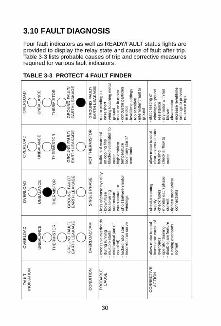
3.10 FAULT DIAGNOSIS
Four fault indicators as well as READY/FAULT status lights areprovided to display the relay state and cause of fault after trip.Table 3-3 lists probable causes of trip and corrective measuresrequired for various fault indicators.
TABLE 3-3 PROTECT 4 FAULT FINDER
FAU
LTIN
DIC
AT
ION
OV
ER
LOA
D
UN
BA
LAN
CE
TH
ER
MIS
TO
R
GR
OU
ND
FA
ULT
/E
AR
TH
LE
AK
AG
E
OV
ER
LOA
D
UN
BA
LAN
CE
TH
ER
MIS
TO
R
GR
OU
ND
FA
ULT
/E
AR
TH
LE
AK
AG
E
OV
ER
LOA
D
UN
BA
LAN
CE
TH
ER
MIS
TO
R
GR
OU
ND
FA
ULT
/E
AR
TH
LE
AK
AG
E
OV
ER
LOA
D
UN
BA
LAN
CE
TH
ER
MIS
TO
R
GR
OU
ND
FA
ULT
/E
AR
TH
LE
AK
AG
E
CO
ND
ITIO
NO
VE
RLO
AD
/JA
MS
ING
LE P
HA
SE
HO
T T
HE
RM
ISTO
RG
RO
UN
D F
AU
LT/
EA
RT
H L
EA
KA
GE
PR
OB
AB
LEC
AU
SE
-ex
cess
ive
over
load
sdu
ring
runn
ing
-m
ultip
le s
tart
s-
mec
hani
cal j
am (i
fen
able
d)-
lock
ed r
otor
sta
rt-
inco
rrec
t run
cur
ve
-lo
ss o
f pha
se b
y ut
ility
-bl
own
fuse
-lo
ose
wiri
ngco
nnec
tion
-w
orn
cont
acto
r-
shor
t bet
wee
n m
otor
win
ding
s
-bu
ildup
of m
ater
ial
on c
oolin
g fin
s-
bloc
ked
vent
ilatio
n to
mot
or-
high
am
bien
tte
mpe
ratu
re-
too
man
y st
arts
/ov
erlo
ads
-m
otor
win
ding
toca
se s
hort
-w
iring
touc
hing
met
algr
ound
-m
oist
ure
in m
otor
-co
nduc
tor p
artic
les
in m
otor
-le
vel/t
ime
setti
ngs
too
sens
itive
-in
term
itten
t fau
lt to
grou
nd
CO
RR
EC
TIV
EA
CT
ION
-al
low
mot
or to
coo
l-
inve
stig
ate
caus
e of
over
load
s-
oper
ator
trai
ning
-di
sabl
e ja
m fe
atur
eru
nnin
g ov
erlo
ads
norm
al
-ch
eck
inco
min
gsu
pply
-ch
eck
fuse
s-
mon
itor e
ach
phas
ecu
rren
t-
tight
en m
echa
nica
lco
nnec
tions
-al
low
mot
or to
coo
l-
clea
n ex
tern
al m
otor
hous
ing
-ch
eck
airf
low
tom
otor
-st
atic
test
ing
ofw
indi
ng to
gro
und
resi
stan
ce-
dry
mot
or w
ith h
otbl
ower
-cl
ean
mot
or-
incr
ease
leve
l/tim
ese
tting
s to
pre
vent
nuis
ance
trip
s
31
4. RELAY TESTING
4.1 COMMISSIONING TESTS
Prior to applying power at a new installation, system operationcan be verified by injecting current through the phase CTs. If a3 phase current injection set is available it would be connectedas shown in figure 2-5 in place of the 3 phase supply and usinga short between the 3 phases in place of the motor. A shortmust be placed across the ground fault CT terminals when do-ing current tests or nuisance ground fault trips will occur.
When a single phase injection set is used, the sensing circuitrysees an unbalance condition as shown in figure 5-2 and ex-plained in the theory of operation section 5. To make the singlephase input appear to the Protect 4A like a 3 phase input, it isnecessary to temporarily connect a capacitor (observe capaci-tor polarity) across the two test points on the terminal board asshown in figure 4.1. Larger capacitors may be substituted. Theactual value is not critical. This shifts the measured values sothat all current readings should be multiplied by a factor of 1.5to set the equivalent 3 phase current.
Figure 4-1 shows a suitable setup for single phase testing. Fig-ure 4-2 shows how to build a 100 amp current source if acommercial unit is not available. All current values can be in-creased by winding n turns in place of the single turn shownand multiplying current readings by n.
To verify that the internal relay circuitry is operating press thefront panel test button. When the test button is pressed, thefault indicators operate and the motor contactor should trip, Testsfor each protection mode are outlined in the sections that fol-low.

32
FIGURE 4-1 SINGLE PHASE INJECTION TESTING
FIGURE 4-2 100 AMP CURRENT SOURCE

33
4.2 OVERLOADS
Set the FULL LOAD — AMPS control to the desired pickup cur-rent and gradually increase the phase current through the phaseCTs. With current applied below the full load pickup point theoverload indicator light will be off. When the pickup current isreached the light will flash.
At the point where the light just begins to flash, the control set-ting and actual three phase RMS current of simulated current(multiplied by the overload factor) using a single phase sourceshould agree.
Example: Verify 3 times overload trip time for a stall setting of 2.5seconds using 100:5 CTs with single phase injection (figure 4-1).
1) Set the Protect 4A FULL LOAD control to 50% for a 50 amppickup level and stall time to 5 seconds.
2) Pass 1 turn from the current source (or n turns and multiplythe current by n) through two of the 100:5 CTs shown in figure4-1 wiring diagram. (Pass the current source through the twoCTs in opposite direction.)
3) Connect 220 uF/25V capacitor (nominal) to Protect 4A testpoints A (+ ve) and B (- ve) on the terminal board. Observepolarity.
4) a) Slowly increase the current until the overload indicatorstarts to flash. This is the pickup level. The injected currentshould be 50A × 1.5 (multiplier factor) = 75A for correctcalibration.
b) Increase the current to 3 × 75A = 225A.
c) Turn off the current. Press front panel TEST and then RE-SET buttons. This clears the internal thermal memory readyfor timing tests.
d) Apply the full 225A immediately while timing. From theoverload curves of figure 3-2, the relay should trip in 21.9seconds. Other overload levels and stall times can also beverified this way. Note that the times will only be as accu-rate as the current multiples of pickup level injected.
5) Repeat steps 2-4 for the 3rd 5 amp phase CT.

34
When checking the time/over current curves for accuracy, it mustbe remembered that previous overloads will shorten the timeavailable since the internal memory is partially full to simulatemotor heating. Before performing timing tests, ensure that fullmemory capacity is available by:
a) removing and re-applying control power.or b) tripping and resetting relay.or c) applying no overloads for a ten minute period.
If the mechanical jam feature has been selected (section 2.9.2)apply current to the motor below the full load setting and waitseveral seconds for the PROTECT 4A to internally determinethat the simulated motor is in a normal run state. Gradually in-crease the current until the relay trips. This should occur at ap-proximately three times the full load pickup point. Since thereis a one second delay between sensing the threshold and ac-tually tripping, the current must be increased slowly.
Use the maximum stall time setting and clear the memory be-fore doing this test to prevent the overload memory from trip-ping before mechanical jam.
4.3 SINGLE PHASING
Set the FULL LOAD—(AMPS) control to a suitable pickup set-ting and apply slightly less than one full load of three phaseinput current. Create a single phase by removing the capacitoracross test posts A and B for a single phase injection setup.After approximately 5 seconds the relay should trip with an un-balance indication.
If the current applied is below 40% of the full load setting, thesingle phase protection is automatically deactivated to preventnuisance tripping on lightly loaded motors where a large un-balance will not cause damage.

35
4.4 GROUND FAULT/EARTH LEAKAGE
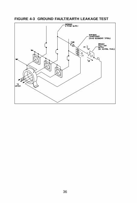
When a ground fault occurs on a three phase system, the corebalance CT will pick up a sine wave current at the system fre-quency. Consequently, to test this protection feature, pass a wirethrough the separate ground fault CT and apply a single phasecurrent. When the current through this wire reaches the groundfault pickup level selected, the relay will trip. Some mine speci-fications require a permanent ground fault test system installedin the switchgear. Fig. 4-3 shows a typical scheme that can beused with the Protect 4A relay.
Ground fault time delays are controlled by an accurate crystalreference and should be drift free. Time delays can be checkedusing a frequency counter or mechanical cycle timer. Thescheme will depend upon the equipment used, however it willbe necessary to use the ground fault current signal to triggerthe timer on and the closure of the output contacts to stop thetimer. A typical setup is shown in figure 4-1. Time delay meas-urements should be made with applied currents of 25% orgreater than the PICKUP — AMPS control setting.
36
FIGURE 4-3 GROUND FAULT/EARTH LEAKAGE TEST
37
4.5 THERMISTOR
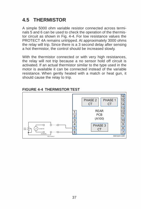
A simple 5000 ohm variable resistor connected across termi-nals 5 and 6 can be used to check the operation of the thermis-tor circuit as shown in Fig. 4-4. For low resistance values thePROTECT 4A remains untripped. At approximately 3000 ohmsthe relay will trip. Since there is a 3 second delay after sensinga hot thermistor, the control should be increased slowly.
With the thermistor connected or with very high resistances,the relay will not trip because a no sensor hold off circuit isactivated. If an actual thermistor similar to the type used in themotor is available it can be connected instead of the variableresistance. When gently heated with a match or heat gun, itshould cause the relay to trip.
FIGURE 4-4 THERMISTOR TEST
23456
RELAY INPUT
5000OHM
OHMETER
MEASURE
PHASE 3CT
REARPCB
(A100)
PHASE 2CT
PHASE 1CT
1
7930122A1.CDR
8910111213141516
38
4.6 4-20 mA OUTPUT
Connect a DC milliammeter to terminals 4 (+ ve) and 5 (- ve).With no input current the meter should read zero. Apply a balanc-ed three phase signal through the current transformers equalto the rated CT current (e.g. 100 amps into 100:5 CTs shouldgive a current reading of 20 mA). The meter should now read20 mA and this reading will be independent of the FULL LOAD— AMPS control setting
Intermediate current values will result in a meter reading of:
meter mA = actual current
currentfull load × +16 4
For example, 75 amps into a 100:5 CT will result in a meterreading of:
75100
16 4 16× + = mA
Use the setup of fig. 4-1 if single phase injection is to be used.Multiply all current values by 1.5 and calculate the output asabove. For example: if 200:5 CTs are used, apply a current of200 x 1.5 = 300 amps through one CT to set an effective inputcurrent of 200 amps.
The output is a current source with a maximum drive voltage ofabout 8 volts. Consequently the programmable controller loador sensing resistance used for these tests must be less than350 ohms or saturation will occur. For loads in this range, theoutput current will be independent of the load resistance.
It is possible to recalibrate the PROTECT 4A to give a linearoutput over a range of 0-20 mA for use with standard currentloop interfaces. Consult factory if this is required.

39
4.7 ROUTINE MAINTENANCE VERIFICATION
A front panel self test feature is provided so that proper opera-tion of the relay and its indicators can be verified. If this testbutton is pushed while a motor is running the motor should shutdown with the 4 fault indicators set. Although this indicates thatthe internal circuitry is operating, fur ther tests are needed tocheck calibration accuracy.
Periodic checks of the overload pickup calibration are possibleby turning the FULL LOAD — AMPS control counter-clockwisewhen the motor is running until the overload light just begins toflash. The dial value at this setting should correspond to theactual average current measured in the motor using a separateammeter. To simulate an overload, set the FULL LOAD —AMPScontrol to a value less than the actual motor current and notethe trip time from the run curves of figure 3-2. Calculate theamount of overload from:
period multiple = actual currentpickup setting
Read the trip time from the overcurrent curves of figure 3-2 us-ing the curve selected by the STALL TIME — (SEC) control.
For example: if 100:5 CTs are used and the motor is drawing75 amps, set the FULL LOAD — AMPS control to 50 amps tosimulate and overload of:
7550
15= . times
Note that any previous overloads or starting inrush currents inthe previous 10 minutes will reduce the total trip time.
It is difficult to simulate other fault conditions directly. The testmethods outlined in the previous sections will be required if thesechecks are to be performed on a routine basis.

40
4.8 PROBLEM TROUBLESHOO TING
TABLE 4-1 PROBLEM TROUBLESHOOTING
SYMPTOM PROBABLE CAUSE ACTION
PeriodicOverloadTripping
– Overload surgesduring running.
– Incorrect run curve.
– Defeat mechanicaljam.
– Use run curve withlonger trip time (higherstall setting).
Overload TripTime Too Short
– Previous overloadsaffect values.
– Jam enabled (1second trip).
– Trip test/reset relaybefore doing timetests.
– Defeat jam feature
Ground FaultNuisance Trip
– Capacive motorinrush currents giveground fault signal.
– CT wiring too close tohigh noise source.
– Increase ground faultlevel/time settings.
– Twist CT wirestogether and routeaway from high currentcables or use shieldedcable.
NuisanceUnbalance Trip
– Non-sinusoidalwaveform.
– May not be suitable forvariable speed driveapplication.
– Check load distribu-tion.
Cannot Reset – No control power. – Status light will be on ifcontrol power applied.
– Push test/reset orpower off/on thenreset.
4-20 mA OutputLow
– Meter or programma-ble controller toohigh.
– Maximum load 350ohms.

41
FIGURE 5-1 HARDWARE BLOCK DIAGRAM
42
5. THEORY OF OPERATION
5.1 HARDWARE
The Protect 4A is able to provide many protection features atlow cost through the use of a powerful single chip microcomputeras shown in block diagram of figure 5-1 and the schematic in-sert. Phase currents are sensed by three current transformerswith 1 amp or 5 amp secondaries. A three phase bridge recti-fier is used to provide a rectified output signal into a fixed bur-den which is shown for balanced and unbalanced conditions infig. 5-2. Under microcomputer control an analog to digital con-vertor continuously samples this signal and generates both thethree phase average for overload curve timing and the phaseminimum for unbalance detection. The burden voltage propor-tional to the three phase average current is also connected to avoltage to current conver tor to provide a 4-20 mA output for aprogrammable controller.
Ground fault/earth leakage sensing is provided by a fourth cur-rent transformer in the current sensing module which encirclesthe three motor conductors and senses ground faults by thereliable core balance (zero sequence) method. Only if a groundfault is present will this CT give an output which is rectified,filtered and compared against a preset value set by the frontpanel ground fault/earth leakage level control. Time delays forboth the ground fault and overload curves are provided by ac-curate crystal controlled time counters under program control.This eliminates inaccuracies and time/temperature drift associ-ated with resistor/capacitor time constant circuits.
A voltage divider circuit using the remote thermistor as one re-sistance element is used to detect if the thermistor resistancehas exceeded the preset threshold point. The voltage acrossthe thermistor is compared to two fixed reference values; thelower reference is the trip resistance point and the higher refer-ence is used to determine if no thermistor is connected to pre-vent nuisance tripping.

43
FIGURE 5-2 SINGLE PHASE DETECTION
FIGURE 5-2a 3 PHASES, BALANCED CONDITION
FIGURE 5-2b SINGLE PHASE CONDITION

44
All front panel and option switches are monitored and stored inthe microprocessor for use by various parts of the program.Indicators and the output relay are strobed under program con-trol as required. Since these are activated by pulse action, poweris conserved and the relay returns to the state before loss ofpower whenever power is reapplied
Reliable operation of the microprocessor under erratic or tran-sient supply conditions is obtained through the use of a powerfail detector which resets the microprocessor to a star t up statewhenever control power is out of range.
In case a transient or system malfunction should cause erraticprogram execution a watchdog timer, consisting of independ-ent circuitry, will reset the microprocessor. The correct strobesignals which are only present during normal program execu-tion must be received or the watchdog timer will be activated
A switch is used to select 120/240 VAC 50/60 Hz for the dualprimary power transformer. This transformer is designed to ac-cept a wide range of input voltages commonly encountered inindustrial applications and is of split bobbin design to minimizecontrol line transients. In addition to voltage regulators for thecircuitry, reference voltages are derived from a temperaturecompensated precision voltage reference to provide stable longterm performance.

45
5.2 FIRMWARE
All mathematical computations and logical operations are per-formed by a program stored in the microcomputer. Executionflow of the routines is shown in the firmware block diagram offig. 5-3.
An initialize routine ensures that the system always comes upin the same state when first powered on. Ground fault and ther-mistor input signals, if present, are used to update delaycounters to determine if there is a trip condition. The unbalanceroutine compares the average and minimum phase current dif-ference to the average. If this difference exceeds the thresholdrepresentative of a single phase condition for a specific timeperiod an unbalance trip condition occurs.
In order to generate an inverse curve the three phase averagecurrent is squared and integrated over time. If the integratedvalue, which represents the thermal heat buildup in the motor,exceeds a threshold determined by the stall time setting therelay trips on overload. When the motor is stopped or not over-loaded the integrated value is reduced with time propor tional tomotor cooling.
Other housekeeping features include analog to digital conver-tor sampling, updating all timers using programmed timers, read-ing switches and sampling internal status. When the relay istripped, the internal program continuously scans for a reset sig-nal and ignores all fault inputs.

46
FIGURE 5-3 FIRMWARE BLOCK DIAGRAM

MULTILIN RELAY WARRANTYMultilin warrants each relay it manufactures to be freefrom defects in material and workmanship under nor-mal use and service for a period of 24 months fromdate of shipment from factory.
In the event of a failure covered by this warranty,Multilin will undertake to repair or replace the relayproviding the warrantor determined that it is defec-tive and it is returned with all transportation chargesprepaid to and from an authorized service centre orthe factory. Repairs or replacement under this war-ranty will be made without charge.
This warranty shall not apply to any relay which hasbeen subject to misuse, negligence, accident, incor-rect installation or use not in accordance withinstructions nor any unit that has been altered out-side a Multilin authorized factory outlet.
Multilin is not liable for contingent or consequentialdamages or expenses sustained as a result of a re-lay malfunction, incorrect application or adjustment.

MOTOR PROTECTION
Made in CanadaPART NO. P4A-M01/94V
215 Anderson Ave., P.O. Box 2700Markham, Ontario, Canada L3P 4C7Tel: (905) 294-6222 Fax: (905) 294-8512