p329 service manual (2)
TRANSCRIPT

SERVICE MANUAL
BATTERY - POWERED PLASTIC STRAPPING TOOL
MODELP329 M/HA / P329 A/A
P329
.sen
.fm/M
AS/
© 0
2.16
Manual for authorized dealers and service points
Buy at Allstrap (866) 779-2673

6-2
INDEX PAGE
1.1 ACCESSORIES 6-31.1.1 Battery . . . . . . . . . . . . . . . . . . . . . . . . . . . . . . . . . . . . . . . . . . . . . . . . . . . . . . . 6-31.1.2 Battery chargers . . . . . . . . . . . . . . . . . . . . . . . . . . . . . . . . . . . . . . . . . . . . . . . 6-31.1.3 Battery tester . . . . . . . . . . . . . . . . . . . . . . . . . . . . . . . . . . . . . . . . . . . . . . . . . . 6-31.1.4 Memory reader for circuit board . . . . . . . . . . . . . . . . . . . . . . . . . . . . . . . . . . . 6-31.1.5 Suspension . . . . . . . . . . . . . . . . . . . . . . . . . . . . . . . . . . . . . . . . . . . . . . . . . . . 6-31.1.6 Fan . . . . . . . . . . . . . . . . . . . . . . . . . . . . . . . . . . . . . . . . . . . . . . . . . . . . . . . . . 6-4
1.2 TECHNICAL DETAILS 6-41.2.1 Strap tension . . . . . . . . . . . . . . . . . . . . . . . . . . . . . . . . . . . . . . . . . . . . . . . . . . 6-41.2.2 Electric schematic Semi Automatic ELS.1082 . . . . . . . . . . . . . . . . . . . . . . . . 6-51.2.3 Connecting plan Semi Automatic . . . . . . . . . . . . . . . . . . . . . . . . . . . . . . . . . . 6-51.2.4 Electric schematic Automatic ELS.1083 . . . . . . . . . . . . . . . . . . . . . . . . . . . . . 6-61.2.5 Connecting plan Automatic . . . . . . . . . . . . . . . . . . . . . . . . . . . . . . . . . . . . . . . 6-6
1.3 CONVERSION PARTS P329 6-71.3.1 Conversion parts for changing of strap width and strap thickness . . . . . . . . . 6-71.3.2 Conversion parts from Semi automatic to Automatic . . . . . . . . . . . . . . . . . . . 6-7
1.4 PERIODIC MAINTENANCE AND CONTROL 6-81.4.1 Procedure . . . . . . . . . . . . . . . . . . . . . . . . . . . . . . . . . . . . . . . . . . . . . . . . . . . . 6-81.4.2 Troubleshooting. . . . . . . . . . . . . . . . . . . . . . . . . . . . . . . . . . . . . . . . . . . . . . . . 6-91.4.3 Battery test . . . . . . . . . . . . . . . . . . . . . . . . . . . . . . . . . . . . . . . . . . . . . . . . . . 6-111.4.4 Checklist . . . . . . . . . . . . . . . . . . . . . . . . . . . . . . . . . . . . . . . . . . . . . . . . . . . . 6-111.4.5 Lubrication rules . . . . . . . . . . . . . . . . . . . . . . . . . . . . . . . . . . . . . . . . . . . . . . 6-111.4.6 Glueing rules . . . . . . . . . . . . . . . . . . . . . . . . . . . . . . . . . . . . . . . . . . . . . . . . 6-121.4.7 Assembly information . . . . . . . . . . . . . . . . . . . . . . . . . . . . . . . . . . . . . . . . . . 6-13
1.5 RECOMMENDED SPARE PARTS 6-20
1.6 MAINTENANCE PLAN P329 6-21
1.7 ACCESSORY TOOLS 6-22
1.8 USE OF ACCESSORY TOOLS 6-23
1.9 ORDERING SPARE PARTS 6-291.9.1 Ordering manuals . . . . . . . . . . . . . . . . . . . . . . . . . . . . . . . . . . . . . . . . . . . . . 6-291.9.2 Ordering address. . . . . . . . . . . . . . . . . . . . . . . . . . . . . . . . . . . . . . . . . . . . . . 6-291.9.3 Finding out of the tool type (item number), the serial number
and the version number: . . . . . . . . . . . . . . . . . . . . . . . . . . . . . . . . . . . . . . . . 6-30
1.10 SERVICE ADDRESS 6-30
1.11 CHART OF TYPES 6-301.11.1 Chart of types P329 M / HA . . . . . . . . . . . . . . . . . . . . . . . . . . . . . . . . . . . . . 6-301.11.2 Chart of types P329 A / A . . . . . . . . . . . . . . . . . . . . . . . . . . . . . . . . . . . . . . . 6-30
Buy at Allstrap (866) 779-2673
6-3
1.1 ACCESSORIES1.1.1 BatteryUse only original Fromm batteries N5.4349 (Li-Ion).
1.1.2 Battery chargersThe battery charger must be ordered separately according to the table mentioned below.
(..) = an adaptor N52.2102 is required.
1.1.3 Battery testerInformation to the Battery tester you will get by FROMM System GmbH.(see 1.10 SERVICE ADDRESS)
1.1.4 Memory reader for circuit boardTo read the memory information of the tools circuit board the reader N7.5154 can be ordered.With this the following data could be read:
• software version• date of software• strapping cycles• calibration current
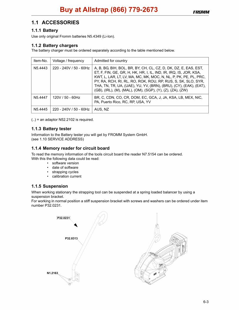
1.1.5 SuspensionWhen working stationary the strapping tool can be suspended at a spring loaded balancer by using a suspension bracket.For working in normal position a stiff suspension bracket with screws and washers can be ordered under item number P32.0231.
Item-No. Voltage / frequency Admitted for country
N5.4443 220 - 240V / 50 - 60Hz A, B, BG, BIH, BOL, BR, BY, CH, CL, CZ, D, DK, DZ, E, EAS, EST, ET, F, FIN, GE, GR, H, HK, HR, I, IL, IND, IR, IRQ, IS, JOR, KSA, KWT, L, LAR, LT, LV, MA, MC, MK, MOC, N, NL, P, PK, PE, PL, PRC, PY, RA, RCH, RI, RL, RO, ROK, ROU, RP, RUS, S, SK, SLO, SYR, THA, TN, TR, UA, (UAE), YU, YV, (BRN), (BRU), (CY), (EAK), (EAT), (GB), (IRL), (M), (MAL), (OM), (SGP), (Y), (Z), (ZA), (ZW)
N5.4447 120V / 50 - 60Hz BR, C, CDN, CO, CR, DOM, EC, GCA, J, JA, KSA, LB, MEX, NIC, PA, Puerto Rico, RC, RP, USA, YV
N5.4445 220 - 240V / 50 - 60Hz AUS, NZ
P32.0231
P32.8313
N1.2163
Buy at Allstrap (866) 779-2673

6-4
For working in alternating positions a turnable suspension bracket with screws and washers can be ordered under item number P32.0223.
1.1.6 Fan In order to avoid overheating of the motor we recommend at environmental temperatures above 40°C / 104°F using the optional fan P32.0228.(see 1.4.7 Assembly information)
1.2 TECHNICAL DETAILS1.2.1 Strap tensionThe tension force values mentioned in the operation manual (500-4000N) are not achievable with each strap. They depend on following factors:
• Hardness of the package,the maximum tension force values are achievable with hard packages.
• Elongation and creep properties of the plastic strap,the maximum tension force values are achievable by using plastic straps with a low elongation.
• Surface quality of the plastic strap,the maximum tension force values are achievable with waxed and embossed straps.
• Strap width, strap thickness,the maximum tension force values are achievable with thick and wide straps.
P32.0223
N1.5105
N2.5623 cP35.2073 c
P32.8302
P35.2069 cN1.2163
c Mobilux EP2
P32.8301 c
Buy at Allstrap (866) 779-2673

6-5
1.2.2 Electric schematic Semi Automatic ELS.1082
1.2.3 Connecting plan Semi Automatic
18VDC red
-
+ red
2 1
UB
M3
2
1
3
red
blue1
2
(-)(+)
M2U
V
Wyellow
violett
brown
Hall3
Hall2
Hall1
GND
+5V
5
4
3
2
1
M1
2
1black
red (+)
(-) optional Fan
blackblack
blackDC
DP
2 1
HA
MManual / 1/2 Auto
P32.8150N51.1127
P32.0213
P32.0228 (optional)
P33.2155
N51.2194
red
red
black
blueredblue black
red
P32.8199
Buy at Allstrap (866) 779-2673

6-6
1.2.4 Electric schematic Automatic ELS.1083
1.2.5 Connecting plan Automatic
18VDC red
-
+ red
2 1
UB
M3
2
1
3
red
blue1
2
(-)(+)
M2U
V
Wyellow
violett
brown
Hall3
Hall2
Hall1
GND
+5V
5
4
3
2
1
M1
2
1black
red (+)
(-)
A
AAuto / Auto
1(C)
4(N0)
optional Fan
blackblack
blackDC
DP
P32.8154
N51.1127
P32.0213
P32.0228 (optional)
P33.2155
N51.2194
red
red
black
bluered
blue blackred
P32.8201
N5.2382
Buy at Allstrap (866) 779-2673
6-7
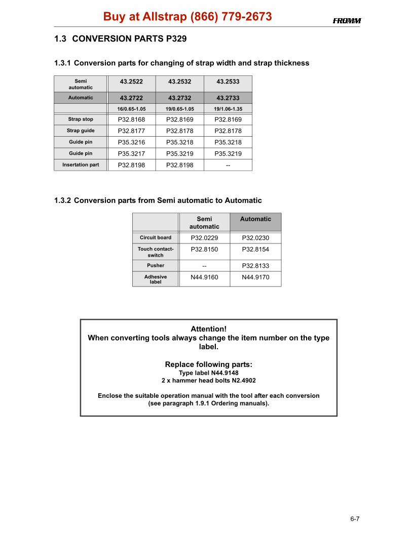
1.3 CONVERSION PARTS P329
1.3.1 Conversion parts for changing of strap width and strap thickness
1.3.2 Conversion parts from Semi automatic to Automatic
Semiautomatic
43.2522 43.2532 43.2533
Automatic 43.2722 43.2732 43.273316/0.65-1.05 19/0.65-1.05 19/1.06-1.35
Strap stop P32.8168 P32.8169 P32.8169
Strap guide P32.8177 P32.8178 P32.8178
Guide pin P35.3216 P35.3218 P35.3218
Guide pin P35.3217 P35.3219 P35.3219
Insertation part P32.8198 P32.8198 --
Semiautomatic
Automatic
Circuit board P32.0229 P32.0230
Touch contact-switch
P32.8150 P32.8154
Pusher -- P32.8133
Adhesive label
N44.9160 N44.9170
Attention!When converting tools always change the item number on the type
label.
Replace following parts:Type label N44.9148
2 x hammer head bolts N2.4902
Enclose the suitable operation manual with the tool after each conversion (see paragraph 1.9.1 Ordering manuals).
Buy at Allstrap (866) 779-2673
6-8
1.4 PERIODIC MAINTENANCE AND CONTROL(Carry out 12- months cycles doing one shift work. Doing more shift work respectively more often.)To avoid damages on the motor shaft the two needle free wheelings N3.4509 and N3.4520 have to bereplaced after 80 000 strapping cycles.
1.4.1 Procedure
Before using check tool for following possible faults:
• Visual test of the tool for loose, lost or damaged parts• Clean all dirty parts of the tool, especially strap abrasion in the tensioning or the welding unit by
using compressed air. (Never use any hard tools like a wire brush or a screw driver for cleaning)
Carry out a test strapping and check following:
• Insertion of the strap
• Strap feed and strap tensioning
• Tensioning force adjustment (see operation manual P329)
• Cutting of the upper strap
• Welding time adjustment (see operation manual P329)
• Seal quality (see operation manual P329)
• Function of the LED - display
Proceed according to paragraph 1.4.2 after a fault appears.For exchange of wearing parts see operation manual P329.
Attention!
Remove battery from tool before each maintenance work.
Never use water or solvents for cleaning the tool’s surface.
Buy at Allstrap (866) 779-2673

6-9
1.4.2 TroubleshootingEnsure before each tool repair that the battery is charged and
the tool’s specific strap is used
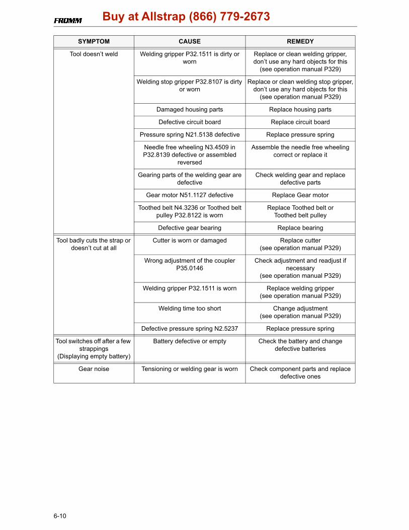
SYMPTOM CAUSE REMEDY
Tool doesn’t work at all Battery is empty or defective Charge or replace battery
Contact problems caused by a broken battery housing
Replace battery
Contact problems caused by a damaged insertation part N51.2194 or damaged motor housings P32.8103
and P32.8105/96
Replace insertation part or motor housing
Contact problem of the internal wires Check contacts and fix them if required or change defective parts
Defective circuit board Replace circuit board
Tool doesn’t tension Tensioning wheel is dirty or worn Clean tensioning wheel or replace it,don’t use any hard objects for this
(see operation manual P329)
P32.8128 is not meshing with P32.8130 because spring N2.5296 is
defective or parts are dirty
Replace spring N2.5296,clean dirty parts
Faulty tensioning wheel or tensioning wheel is assembled reversed
Correct assembling(see operation manual P329)
Grippers are dirty, worn or wrongly assembled
Replace grippers, clean them or assemble correct,
don’t use any hard objects for this(see operation manual P329)
Gearing parts from the tensioning gear are defective
Check tensioning gear and replace defective parts
Defective circuit board Replace circuit board
Defective gear bearings Replace bearings
Needle free wheeling N3.4509 in gear wheel P32.8139 or N3.4520 in conical
gear wheel P32.8138 assembled reversed or defective
Assemble the needle free wheeling correct or replace it
Tensioning wheel turns back immediately after the
tensioning cycle
Defective needle free wheeling N3.4509 in P32.8134
Check parts and replace if necessary
Buy at Allstrap (866) 779-2673
6-10
Tool doesn’t weld Welding gripper P32.1511 is dirty or worn
Replace or clean welding gripper,don’t use any hard objects for this
(see operation manual P329)
Welding stop gripper P32.8107 is dirty or worn
Replace or clean welding stop gripper,don’t use any hard objects for this
(see operation manual P329)
Damaged housing parts Replace housing parts
Defective circuit board Replace circuit board
Pressure spring N21.5138 defective Replace pressure spring
Needle free wheeling N3.4509 in P32.8139 defective or assembled
reversed
Assemble the needle free wheeling correct or replace it
Gearing parts of the welding gear are defective
Check welding gear and replace defective parts
Gear motor N51.1127 defective Replace Gear motor
Toothed belt N4.3236 or Toothed belt pulley P32.8122 is worn
Replace Toothed belt or Toothed belt pulley
Defective gear bearing Replace bearing
Tool badly cuts the strap or doesn’t cut at all
Cutter is worn or damaged Replace cutter (see operation manual P329)
Wrong adjustment of the coupler P35.0146
Check adjustment and readjust if necessary
(see operation manual P329)
Welding gripper P32.1511 is worn Replace welding gripper(see operation manual P329)
Welding time too short Change adjustment(see operation manual P329)
Defective pressure spring N2.5237 Replace pressure spring
Tool switches off after a few strappings
(Displaying empty battery)
Battery defective or empty Check the battery and change defective batteries
Gear noise Tensioning or welding gear is worn Check component parts and replace defective ones
SYMPTOM CAUSE REMEDY
Buy at Allstrap (866) 779-2673
6-11
1.4.3 Battery testThe battery should be checked while each maintenance with a battery tester.Information to the Battery tester you will get by FROMM System GmbH.(see 1.10 SERVICE ADDRESS)
• Li-Ion-Batteries 18V / (4,0Ah) must be replaced at a capacity less than approx. 60% (2,4 Ah)
1.4.4 ChecklistCarry out some test strappings and check following tool components.
• Inserting of the strap
• Insert battery in the tool and check function of the LED-display (see operation manual P329)
• Strap feed and strap tension
• Tension force adjustment (see operation manual P329)
• Cutting of the upper strap
• Welding time adjustment (see operation manual P329)
• Seal quality (see operation manual P329)
• Function of the LED-display (see operation manual P329)
• Correct type label
1.4.5 Lubrication rulesAll gear parts have to be lubricated with MOLYKOTE BR2 PLUS grease.All other parts have to be lubricated according to the explosion drawing.Lubrication interval: While each maintenance or after 12 months at the latest.
Particular note:
All bearing parts of the welding unit have to be cleaned and lubricated as follows:
g P32.1511c Mobilux EP2g Klüber Isoflex Alltime SL2h Klüber Isoflex NBU 15
P32.1029 g
N3.1702 (6X) g
P32.1027 g
h P32.1028
c P32.1035
grease hereP32.1024 h
c P32.1035
Buy at Allstrap (866) 779-2673
6-12
Eccentric shaft P32.8121, Spring slide P32.8116, Spring bolt P32.8117 and the Pressure spring N21.5138 have to be greased as follows:
Lubrication interval: While each maintenance or after 12 months at the latest.
1.4.6 Glueing rules
c P32.8121
c P32.8116
P32.8117 c
c Mobilux EP2
N21.5138 c
c
N21.2145
N2.2145
P32.8128
N1.2188
P32.0205
P32.8131P32.2016
N3.1159
The Bearing N3.1159 has to be glued intothe gear wheel P32.2016 with LOCTITE 603.
The parallel pins N21.2145 have to be glued into the gear body P32.8131 using LOCTITE 603.
Gear wheel P32.8128 and parallel pins N2.2145have to be glued with LOCTITE 603
The screws N1.2188 have to be glued additionally in the wheel P32.0205 usingLOCTITE 222.Don‘t damage the teeth when loosening ortightening the screws.
Buy at Allstrap (866) 779-2673

6-13
1.4.7 Assembly information
P32.8137
N1.1305
N1.6504
P32.8157
The bolt P32.8137 has to be glued into thebody P32.8157 using Loctite 603.
The screws N1.1305 have to be gluedwith Loctite 222.
P32.8159
N2.2119
The parallel pin N2.2119 has to be glued into the end cover P32.8159with Loctite 603.
P32.8108
Grippers
One sided sealed bearings N3.1172 in the tensioning wheel.The sealed side has to face to the outside. (see drawing)
When installing the grippers into the holder P32.8108 pay attention to the direction of the teeth (see drawing).
Buy at Allstrap (866) 779-2673
6-14
Pay attention to the mounting position of the needle free wheelings N3.4509 and N3.4520.The rolling direction is stamped in at the front side of the free wheelings.
Position of the joint from slide bearings
Pay attention to the position of the joint from the slide bearing N31.3115 (see drawing).
N3.4509
P32.8134
P32.8138N3.4509N3.4520 P32.8139
12,55 +-0,2
position jointN31.3115
press in pins flush
(4,4
)
P32.8157
P32.8137
Buy at Allstrap (866) 779-2673

6-15
Pay attention to the position of the joint from the slide bearings N3.3172 and N3.3150. (see drawing)
Mounting of dowel pin N21.2140
Mount the dowel pin N21.2140 in the shown position.
N3.3150
position joint
12
N2.2119
P32.8159
position joint
3 X N21.2145
P32.8131
N3.3172
P32.8131
press in measure parallel pin N2.2119into end cover P32.8159
press in pins N21.2145 flush
P32.8121
N21.2140
P32.8120
The edge must bein this position
Buy at Allstrap (866) 779-2673
6-16
Mounting of the optional fan P32.0228:
- Unscrew the motor housing and remove it.- Disconnect the plugs of the motor P32.0213 from the circuit board. Remove the motor.- Insert the fan N51.5464 at the prepared place. The cable shows up to the right.- Attach the corresponding hole of the fan to the protruding pin of the motor housing P32.8103.- Attach the fan with the supplied screws N1.7221.- Plug in the connector on the shown place of the circuit board.- Put in the motor and connect it. Take care that the colours of the connecting cables are conform to the
connector sockets. The gear wheels of the motor have to touch their counterparts correctly.- Before closing the motor housing take care that no cables can be jammed or damaged.- Assemble the motor housing.
Connecting plan
Motor housing
P32.0213
P32.0228
P32.8103attach fan to the pin
N51.5464
N1.7221
Buy at Allstrap (866) 779-2673
6-17
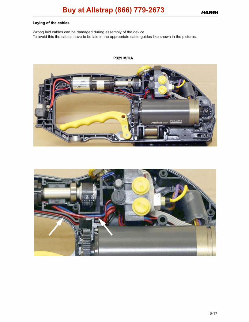
Laying of the cables
Wrong laid cables can be damaged during assembly of the device.To avoid this the cables have to be laid in the appropriate cable guides like shown in the pictures.
P329 M/HA
Buy at Allstrap (866) 779-2673

6-18
P329 A/A
View without motor
Buy at Allstrap (866) 779-2673

6-19
Sockets for the motor on the circuit board
Not fully plugged in plugs lead to burns at plugs and sockets and finally causing disturbances.In order to avoid this, the plugs must always be fully inserted into the sockets and have to be greased with Nyogel 760G.
!m
ax 4,5
N51.2199P33.2127
right
wrongburned
If defective plugs have to be changed take care to the max. Ø 4,5 mm.
Grease the plug N51.2199 with the contact grease Nyogel 760G.
Buy at Allstrap (866) 779-2673

6-20
1.5 RECOMMENDED SPARE PARTSFollowing spare parts are recommended for stock keeping:
* = wearing partsStock only parts from tools that are in sale.
Item-No. Description Pieces per toolN1.1196 Screw 3N1.1305 Screw 6N1.1928 Screw 1N1.1934 Flat head screw 3N1.1943 Screw 2N1.1973 Screw 1N1.6504 Safety washer 24N1.7211 PT-screw 8N2.1118 Security ring 2N2.1121 Security ring 5N2.1606 Spring ring 1N3.1702 Ball 6N3.4509 Free wheeling 2N3.4520 Free wheeling 1
N51.1127* Gear motor 1N51.2194 Insertation part 1P32.0218 Body 1P32.0213* Electric motor 1
P32.0229/30 Circuit board 1P32.8103 Motor housing 1
P32.8105/96 Motor housing 1P32.8150/54 Touch contact-switch 1P32.1511* Welding gripper 1P32.1024 Rocker 1P32.1028 Bolt 1P32.1035 Driver 2P32.8107* Welding stop gripper 1P32.8108 Holder 1P32.8109* Gripper 1P32.8110* Gripper 1P32.8111* Gripper 1P32.8159 End cover 1P35.3214* Cutter 1P35.3203* Tensioning wheel 1
Buy at Allstrap (866) 779-2673
6-21
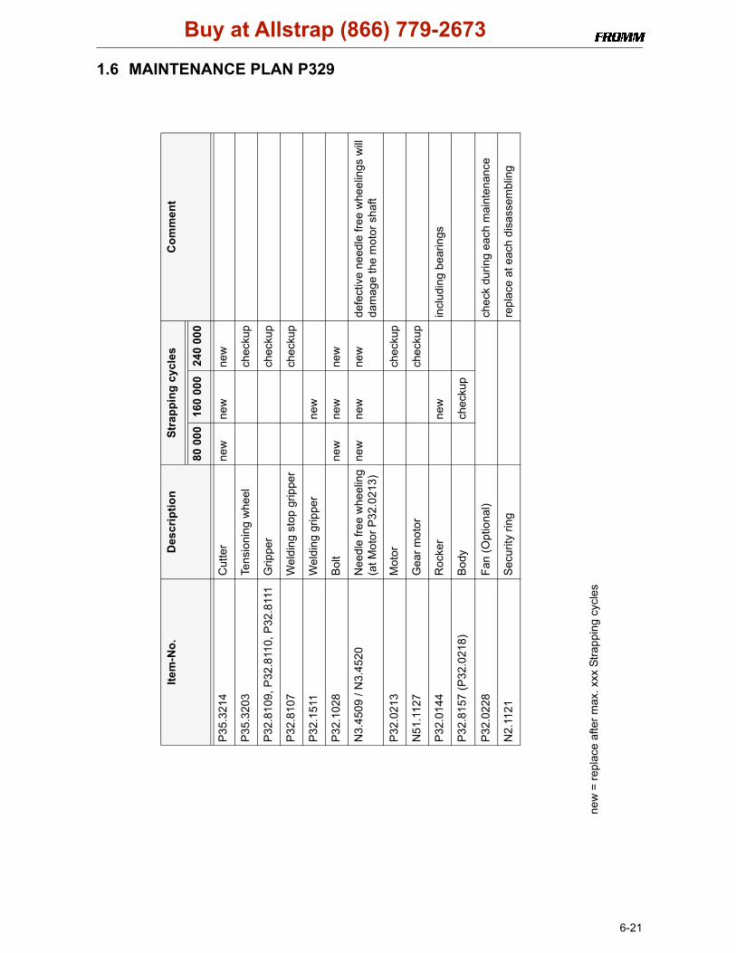
1.6 MAINTENANCE PLAN P329
Com
men
t
defe
ctiv
e ne
edle
free
whe
elin
gs w
ill
dam
age
the
mot
or s
haft
incl
udin
g be
arin
gs
chec
k du
ring
each
mai
nten
ance
repl
ace
at e
ach
disa
ssem
blin
g
Stra
ppin
g cy
cles 24
0 00
0
new
chec
kup
chec
kup
chec
kup
new
new
chec
kup
chec
kup
160
000
new
new
new
new
new
chec
kup
80 0
00
new
new
new
Des
crip
tion
Cut
ter
Tens
ioni
ng w
heel
Grip
per
Wel
ding
sto
p gr
ippe
r
Wel
ding
grip
per
Bol
t
Nee
dle
free
whe
elin
g(a
t Mot
or P
32.0
213)
Mot
or
Gea
r mot
or
Roc
ker
Bod
y
Fan
(Opt
iona
l)
Sec
urity
ring
Item
-No.
P35
.321
4
P35
.320
3
P32
.810
9, P
32.8
110,
P32
.811
1
P32
.810
7
P32
.151
1
P32
.102
8
N3.
4509
/ N
3.45
20
P32
.021
3
N51
.112
7
P32
.014
4
P32
.815
7 (P
32.0
218)
P32
.022
8
N2.
1121
new
= re
plac
e af
ter m
ax. x
xx S
trapp
ing
cycl
es
Buy at Allstrap (866) 779-2673
6-22
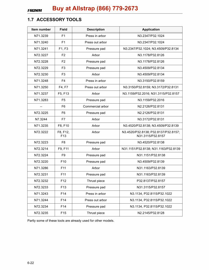
1.7 ACCESSORY TOOLS
Partly some of these tools are already used for other models.
Item number Field Description Application
N71.3239 F1 Press in arbor N3.2347/P32.1024
N71.3240 F1 Press out arbor N3.2347/P32.1024
N71.3241 F1, F3 Pressure pad N3.2347/P32.1024; N3.4509/P32.8134
N72.3227 F2 Arbor N3.1178/P32.8126
N72.3228 F2 Pressure pad N3.1178/P32.8126
N72.3229 F3 Pressure pad N3.4509/P32.8134
N72.3230 F3 Arbor N3.4509/P32.8134
N71.3248 F4 Press in arbor N3.3150/P32.8159
N71.3250 F4, F7 Press out arbor N3.3150/P32.8159; N3.3172/P32.8131
N71.3237 F5, F13 Arbor N3.1159/P32.2016; N31.3115/P32.8157
N71.3283 F5 Pressure pad N3.1159/P32.2016
-- F6 Commercial arbor N2.2126/P32.8131
N72.3225 F6 Pressure pad N2.2126/P32.8131
N7.3244 F7 Arbor N3.3172/P32.8131
N71.3235 F8, F10 Arbor N3.4520/P32.8138; N3.4509/P32.8139
N72.3222 F8, F12, F13
Arbor N3.4520/P32.8138; P32.8137/P32.8157; N31.3115/P32.8157
N72.3223 F8 Pressure pad N3.4520/P32.8138
N72.3214 F9, F11 Arbor N31.1151/P32.8138; N31.1163/P32.8139
N72.3224 F9 Pressure pad N31.1151/P32.8138
N72.3220 F10 Pressure pad N3.4509/P32.8139
N71.3286 F11 Arbor N31.1163/P32.8139
N72.3231 F11 Pressure pad N31.1163/P32.8139
N72.3232 F12 Thrust piece P32.8137/P32.8157
N72.3233 F13 Pressure pad N31.3115/P32.8157
N71.3243 F14 Press in arbor N3.1134, P32.8115/P32.1022
N71.3244 F14 Press out arbor N3.1134, P32.8115/P32.1022
N72.3234 F14 Pressure pad N3.1134, P32.8115/P32.1022
N72.3235 F15 Thrust piece N2.2145/P32.8128
Buy at Allstrap (866) 779-2673
6-23
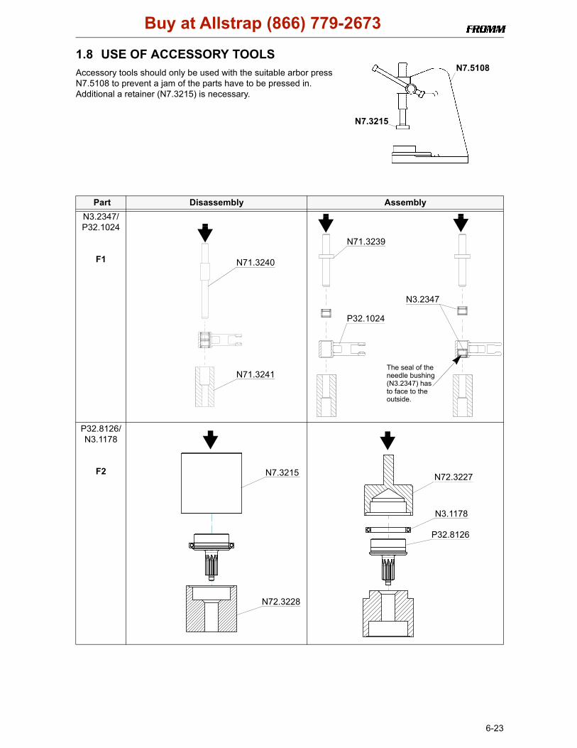
1.8 USE OF ACCESSORY TOOLS Accessory tools should only be used with the suitable arbor press N7.5108 to prevent a jam of the parts have to be pressed in. Additional a retainer (N7.3215) is necessary.
Part Disassembly AssemblyN3.2347/P32.1024
F1
P32.8126/N3.1178
F2
N7.5108
N7.3215
N71.3240
N71.3241
N71.3239
P32.1024
N3.2347
The seal of the needle bushing(N3.2347) has to face to theoutside.
N7.3215
N72.3228
N3.1178
P32.8126
N72.3227
Buy at Allstrap (866) 779-2673
6-24
P32.8134/N3.4509
F3
P32.8159/N3.3150
F4
P32.2016/N3.1159
F5
Part Disassembly Assembly
N72.3230
N71.3241
N3.4509*
P32.8134
N72.3229
*Pay attention to theassembling directionsee assembly information.
N71.3250
P32.8159
N3.3150
N71.3248
*Pay attention to the direction of the jointsee assembly information
N71.3237
P32.2016N3.1159
N71.3283
Buy at Allstrap (866) 779-2673
6-25
P32.8131/N2.2126
F6
P32.8131/N3.3172
F7
P32.8138/N3.4520
F8
Part Disassembly Assembly
N72.3225
Arbor
N2.2126P32.8131
press-in measure 20mm
N71.3250 N7.3244
N3.3172
P32.8131
*Pay attention to the direction of the jointsee assembly information
N72.3222
N72.3223 P32.8138
N3.4520
N71.3235
*Pay attention to theassembling directionsee assembly information.
Buy at Allstrap (866) 779-2673

6-26
P32.8138/N31.1151
F9
P32.8139/N3.4509
F10
P32.8139/N31.1163
F11
Part Disassembly Assembly
N72.3224
N72.3214
P32.8138
N31.1151
N71.3235
N72.3220
P32.8139
N3.4509
*Pay attention to theassembling directionsee assembly information.
N71.3286
N72.3231
N72.3214
P32.8139
N31.1163
Buy at Allstrap (866) 779-2673
6-27
P32.8157/P32.8137
F12
P32.8157/N31.3115
F13
Part Disassembly Assembly
N72.3222 N72.3232
P32.8137
P32.8157
*See also glueing rulesand Assembly information
N72.3222
N72.3233
N71.3237
N31.3115
P32.8157
*Pay attention to the direction of the jointsee assembly information
Buy at Allstrap (866) 779-2673

6-28
P32.1022/N3.1134/P32.8115
F14
Part Assembly
P32.8128/N2.2145
F15
Part Disassembly Assembly
N72.3234
N71.3244
P32.8115
N3.1134
P32.1022
N71.3243
N72.3235
P32.8128 N2.2145
*See also glueing rules
*Attention! Different hole spacings
Buy at Allstrap (866) 779-2673
6-29
1.9 ORDERING SPARE PARTSOn principle spare part numbers should be taken from the drawings or spare parts lists. Check if the version number of the tool and the spare parts list are the same.Type dependent spare parts should be ordered as follows:
Ordering example Ordering a strap guide:
• Take item numbers of the strap guide from drawing (P32.8177/78)• Find out the tool type in which the strap guide should be assembled (e.g. 43.2533)• Find out the item number of the needed strap guide by using the type dependent spare parts lists
(for type 43.2533 it is strap guide P32.8178).
Order as follows if 10 strap guides are needed:P32.8178 Strap guide 10 pcs.
1.9.1 Ordering manualsWhen converting tools make sure that the used manual has still validity.If tools change their item number because of the conversion (see chart of types) the adequate manual must be ordered as follows.
Ordering example: Tool item number: 43.2533Version number: 01Language of the manual: de
The manual order for this tool must look as follows:43253301.deIf the manual is needed in another language replace the shorthand expression "de" (see table).
1.9.2 Ordering addressSpare parts and manuals can be ordered at:
Fromm Holding AG Phone: +41(0) 41 741 57 41Hinterbergstrasse 26 Fax: +41(0) 41 741 57 60CH-6330 Cham e-mail: [email protected]
de German
en English
fr French
it Italian
nl Dutch
po Portuguese
se Swedish
fin Finnish
sp Spanish
ru Russian
cz Czech
hu Hungarian
pl Polish
sk Slovakian
tr Turkish
Buy at Allstrap (866) 779-2673
6-30
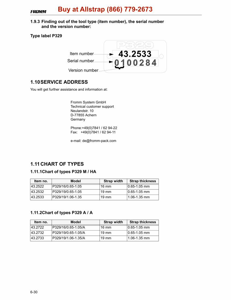
1.9.3 Finding out of the tool type (item number), the serial number and the version number:
Type label P329
1.10SERVICE ADDRESSYou will get further assistance and information at:
Fromm System GmbHTechnical customer supportNeulandstr. 10D-77855 AchernGermany
Phone:+49(0)7841 / 62 94-22Fax: +49(0)7841 / 62 94-11
e-mail: [email protected]
1.11 CHART OF TYPES1.11.1Chart of types P329 M / HA
1.11.2Chart of types P329 A / A
Item no. Model Strap width Strap thickness43.2522 P329/16/0.65-1.05 16 mm 0.65-1.05 mm43.2532 P329/19/0.65-1.05 19 mm 0.65-1.05 mm43.2533 P329/19/1.06-1.35 19 mm 1.06-1.35 mm
Item no. Model Strap width Strap thickness43.2722 P329/16/0.65-1.05/A 16 mm 0.65-1.05 mm 43.2732 P329/19/0.65-1.05/A 19 mm 0.65-1.05 mm 43.2733 P329/19/1.06-1.35/A 19 mm 1.06-1.35 mm
43.2533
{
Item number
Serial number
Version number
Buy at Allstrap (866) 779-2673
7-1P329.0001_2.01_en.z
*see Ordering spare parts
A1
B C
23
45
6
D
3N
21.2
145
2P3
5.32
01
N3.
1172
2N
3.21
07
N3.
1172
N1.
6504
3N
2.21
19
1P3
2.81
77/7
8*
P32.
8108
P32.
8110
4N
1.13
05
N1.
6504
N1.
2222
P32.
8168
/69*
N1.
6504
N1.
1911
P32.
8118
N1.
1928
N1.
6504
P32.
8158
N44
.914
8
N1.
1973
N1.
1943
N2.
4902
2P3
5.32
03
P32.
0222
N2.
2147
N3.
1185
P32.
0207
P32.
0219
/20
1 M
obilu
x EP
2
2 M
olyk
ote
BR 2
plu
s
3 L
octit
e 60
3
4 L
octit
e 22
2
5 K
lübe
r Iso
flex
Allti
me
SL2
6 K
lübe
r Iso
flex
NBU
15
7
1 N
m
8
Orie
ntat
ion
9 N
yoG
el 7
60G
N3.
3150
N41
.912
7
P32.
0221
P32.
0218
P32.
8159
P32.
8109
P32.
8111
N1.
1196
N1.
1934
N2.
2124
N4.
9159
N2.
4902
Buy at Allstrap (866) 779-2673
7-2 P329.0001_2.01_en.z
*see Ordering spare parts
A7
B C
89
1011
12
D
1P3
2.81
16
1N
2.51
57
N2.
2443
4N
1.13
05
N1.
6504
P32.
8107
5P3
2.15
11
6P3
2.10
28P32.
1032
N2.
5178
P32.
1710
N1.
6331
P35.
3220
P32.
1251
N2.
1121 N
1.65
04P3
5.32
23
P35.
3221
1P3
2.10
35
1P3
2.10
35
N2.
3364
N1.
6504
N1.
1910
N31
.311
5
P35.
3216
/18*
P35.
3217
/19*
N2.
2193
N1.
1553
P32.
0203
P32.
0218
1P3
2.81
21
N2.
2187
P32.
8120
P32.
8106
P35.
0146
N2.
2110
N21
.214
0
P32.
0219
/20
P32.
8122
N2.
5237
1 M
obilu
x EP
2
2 M
olyk
ote
BR 2
plu
s
3 L
octit
e 60
3
4 L
octit
e 22
2
5 K
lübe
r Iso
flex
Allti
me
SL2
6 K
lübe
r Iso
flex
NBU
15
7
1 N
m
8
Orie
ntat
ion
9 N
yoG
el 7
60G
N2.
1118
1P3
2.81
17
1N
21.5
138
P32.
8157
P35.
3215
1P3
5.32
14
5N
3.17
02(6
x)
5P3
2.10
27
5P3
2.10
29
N2.
1121
P32.
8195
N2.
1121
P32.
8198
/--*
Buy at Allstrap (866) 779-2673
7-3P329.0001_2.01_en.z
*see Ordering spare parts
A13
B C
1415
1617
18
D
N3.
1134
N3.
2347
N3.
2347
N3.
1134
2N
1.63
313
N3.
1159
2P3
2.20
16 2N
1.63
31 N2.
2190
8N
3.45
09 2P3
2.81
34
2P3
2.81
29
N31
.116
9
N3.
1185
N1.
2189
2P3
2.81
28
N2.
1610
3N
2.21
45
2P3
5.31
042N
3.21
05
N2.
2126
N3.
3172
P32.
8131
1N
21.5
139
1N
21.5
219
P31.
1124
1P3
2.81
25
3P3
2.81
37
N21
.214
4
P32.
1022
P33.
0204
P32.
0207
P32.
8132
2N
2.21
42P32.
2012
6P3
2.10
24
P32.
0144
P32.
0206
P32.
0205
P32.
0204
P32.
0208
P32.
0209
N2.
2180
4N
1.21
88
2N
2.52
96
P32.
0219
/20
P32.
0202
2P3
2.81
15
1 M
obilu
x EP
2
2 M
olyk
ote
BR 2
plu
s
3 L
octit
e 60
3
4 L
octit
e 22
2
5 K
lübe
r Iso
flex
Allti
me
SL2
6 K
lübe
r Iso
flex
NBU
15
7
1 N
m
8
Orie
ntat
ion
9 N
yoG
el 7
60G
2P3
2.81
30
2P3
2.81
27N
31.1
120
P32.
0218
2N
1.63
86
N3.
1178
2P3
2.81
26
Buy at Allstrap (866) 779-2673

7-4 P329.0001_2.01_en.z
*see Ordering spare parts
A19
B C
2021
2223
24
D
(N43
.919
2)
(N44
.916
0/70
)*
(N44
.910
4)
N1.
7211
1N
61.6
220
(P33
.211
5)
9N
51.2
194
N21
.512
4
P32.
0213
N2.
1118
P32.
0214
N4.
3236
2P3
2.01
59P32.
8136
P32.
0211
P32.
0212
2P3
2.81
38
8N
3.45
20
1N
6.62
32
1 M
obilu
x EP
2
2 M
olyk
ote
BR 2
plu
s
3 L
octit
e 60
3
4 L
octit
e 22
2
5 K
lübe
r Iso
flex
Allti
me
SL2
6 K
lübe
r Iso
flex
NBU
15
7
1 N
m
8
Orie
ntat
ion
P32.
0219
/20
(P32
.200
9)P3
3.21
55
9 N
yoG
el 7
60G
N31
.115
1
P32.
8105
/96*
N1.
7211
N1.
7207
7N
1.19
347N
1.19
72
N5.
2702
N3.
2362
2N
1.63
05N
31.1
118
8N
3.45
09
N31
.116
32
P32.
8139
1N
6.62
24
(P30
.121
0)P3
2.81
99/8
201*P3
2.02
29/3
0
P32.
8154
*
N5.
2382
*
(N43
.919
2)
P32.
8103
(N51
.547
7)
P33.
2145
P32.
8141
N1.
7222
N51
.112
7
P32.
8140
N31
.112
0
P32.
8133
*
N43
.916
4
N1.
6504
N2.
1606
7N
1.19
66
P32
.121
5
N1.
7211
7N
1.19
27
N1.
6504
P32.
8142
P32.
8150
*
2P3
2.01
59
9(N
51.2
199)
(P33
.212
7)
Buy at Allstrap (866) 779-2673
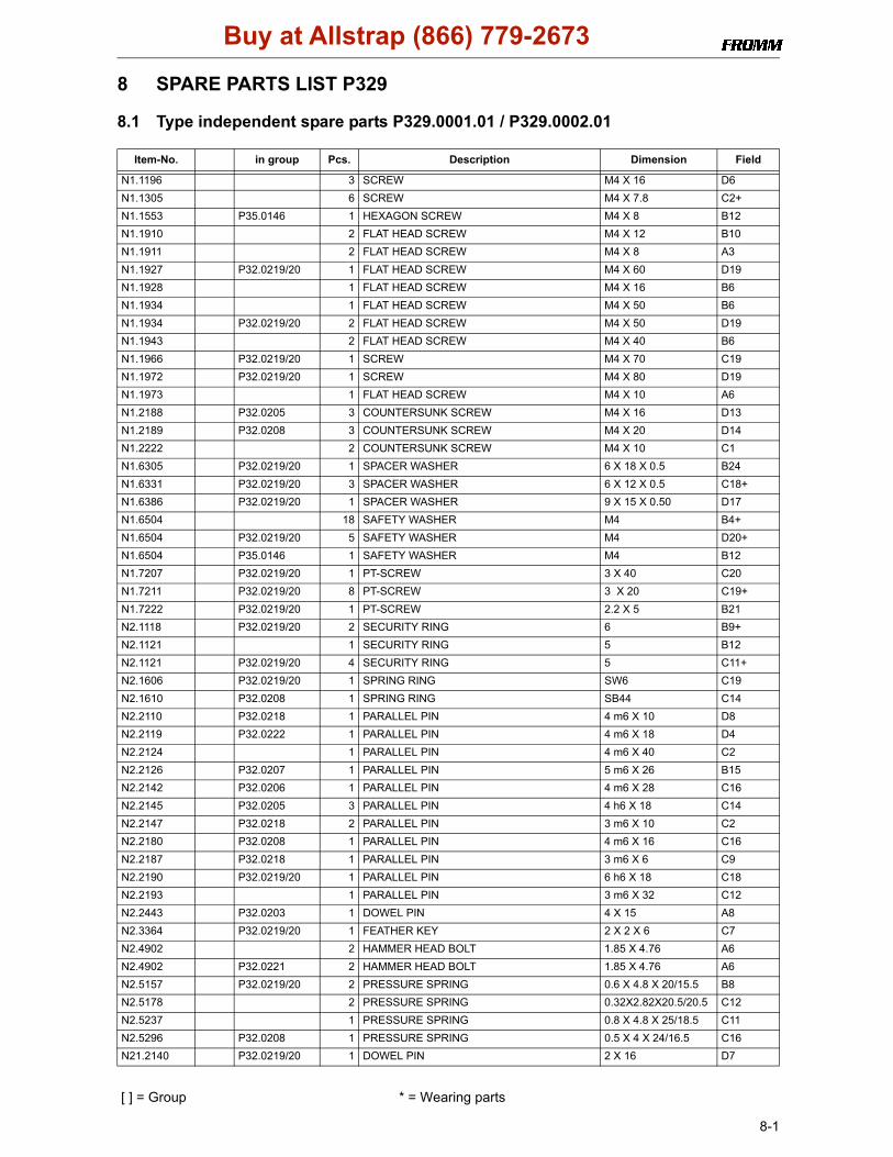
[ ] = Group * = Wearing parts
8-1
8 SPARE PARTS LIST P329
8.1 Type independent spare parts P329.0001.01 / P329.0002.01
Item-No. in group Pcs. Description Dimension Field
N1.1196 3 SCREW M4 X 16 D6N1.1305 6 SCREW M4 X 7.8 C2+N1.1553 P35.0146 1 HEXAGON SCREW M4 X 8 B12N1.1910 2 FLAT HEAD SCREW M4 X 12 B10N1.1911 2 FLAT HEAD SCREW M4 X 8 A3N1.1927 P32.0219/20 1 FLAT HEAD SCREW M4 X 60 D19N1.1928 1 FLAT HEAD SCREW M4 X 16 B6N1.1934 1 FLAT HEAD SCREW M4 X 50 B6N1.1934 P32.0219/20 2 FLAT HEAD SCREW M4 X 50 D19N1.1943 2 FLAT HEAD SCREW M4 X 40 B6N1.1966 P32.0219/20 1 SCREW M4 X 70 C19N1.1972 P32.0219/20 1 SCREW M4 X 80 D19N1.1973 1 FLAT HEAD SCREW M4 X 10 A6N1.2188 P32.0205 3 COUNTERSUNK SCREW M4 X 16 D13N1.2189 P32.0208 3 COUNTERSUNK SCREW M4 X 20 D14N1.2222 2 COUNTERSUNK SCREW M4 X 10 C1N1.6305 P32.0219/20 1 SPACER WASHER 6 X 18 X 0.5 B24N1.6331 P32.0219/20 3 SPACER WASHER 6 X 12 X 0.5 C18+N1.6386 P32.0219/20 1 SPACER WASHER 9 X 15 X 0.50 D17N1.6504 18 SAFETY WASHER M4 B4+N1.6504 P32.0219/20 5 SAFETY WASHER M4 D20+N1.6504 P35.0146 1 SAFETY WASHER M4 B12N1.7207 P32.0219/20 1 PT-SCREW 3 X 40 C20N1.7211 P32.0219/20 8 PT-SCREW 3 X 20 C19+N1.7222 P32.0219/20 1 PT-SCREW 2.2 X 5 B21N2.1118 P32.0219/20 2 SECURITY RING 6 B9+N2.1121 1 SECURITY RING 5 B12N2.1121 P32.0219/20 4 SECURITY RING 5 C11+N2.1606 P32.0219/20 1 SPRING RING SW6 C19N2.1610 P32.0208 1 SPRING RING SB44 C14N2.2110 P32.0218 1 PARALLEL PIN 4 m6 X 10 D8N2.2119 P32.0222 1 PARALLEL PIN 4 m6 X 18 D4N2.2124 1 PARALLEL PIN 4 m6 X 40 C2N2.2126 P32.0207 1 PARALLEL PIN 5 m6 X 26 B15N2.2142 P32.0206 1 PARALLEL PIN 4 m6 X 28 C16N2.2145 P32.0205 3 PARALLEL PIN 4 h6 X 18 C14N2.2147 P32.0218 2 PARALLEL PIN 3 m6 X 10 C2N2.2180 P32.0208 1 PARALLEL PIN 4 m6 X 16 C16N2.2187 P32.0218 1 PARALLEL PIN 3 m6 X 6 C9N2.2190 P32.0219/20 1 PARALLEL PIN 6 h6 X 18 C18N2.2193 1 PARALLEL PIN 3 m6 X 32 C12N2.2443 P32.0203 1 DOWEL PIN 4 X 15 A8N2.3364 P32.0219/20 1 FEATHER KEY 2 X 2 X 6 C7N2.4902 2 HAMMER HEAD BOLT 1.85 X 4.76 A6N2.4902 P32.0221 2 HAMMER HEAD BOLT 1.85 X 4.76 A6N2.5157 P32.0219/20 2 PRESSURE SPRING 0.6 X 4.8 X 20/15.5 B8N2.5178 2 PRESSURE SPRING 0.32X2.82X20.5/20.5 C12N2.5237 1 PRESSURE SPRING 0.8 X 4.8 X 25/18.5 C11N2.5296 P32.0208 1 PRESSURE SPRING 0.5 X 4 X 24/16.5 C16N21.2140 P32.0219/20 1 DOWEL PIN 2 X 16 D7
Buy at Allstrap (866) 779-2673
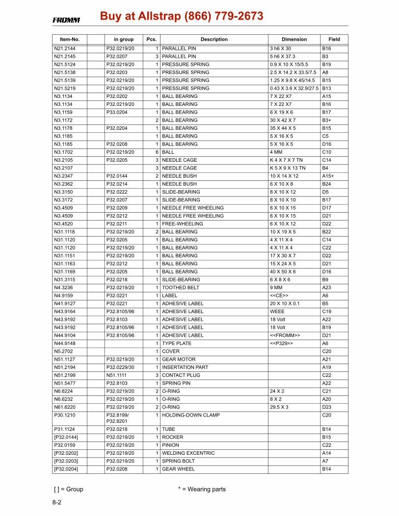
[ ] = Group * = Wearing parts
8-2
N21.2144 P32.0219/20 1 PARALLEL PIN 3 h6 X 30 B16N21.2145 P32.0207 3 PARALLEL PIN 5 h6 X 37.3 B3N21.5124 P32.0219/20 1 PRESSURE SPRING 0.9 X 10 X 15/5.5 B19N21.5138 P32.0203 1 PRESSURE SPRING 2.5 X 14.2 X 33.5/7.5 A8N21.5139 P32.0219/20 1 PRESSURE SPRING 1.25 X 9.8 X 45/14.5 B15N21.5219 P32.0219/20 1 PRESSURE SPRING 0.43 X 3.6 X 32.9/27.5 B13N3.1134 P32.0202 1 BALL BEARING 7 X 22 X7 A15N3.1134 P32.0219/20 1 BALL BEARING 7 X 22 X7 B16N3.1159 P33.0204 1 BALL BEARING 6 X 19 X 6 B17N3.1172 2 BALL BEARING 30 X 42 X 7 B3+N3.1178 P32.0204 1 BALL BEARING 35 X 44 X 5 B15N3.1185 1 BALL BEARING 5 X 16 X 5 C5N3.1185 P32.0208 1 BALL BEARING 5 X 16 X 5 D16N3.1702 P32.0219/20 6 BALL 4 MM C10N3.2105 P32.0205 3 NEEDLE CAGE K 4 X 7 X 7 TN C14N3.2107 3 NEEDLE CAGE K 5 X 9 X 13 TN B4N3.2347 P32.0144 2 NEEDLE BUSH 10 X 14 X 12 A15+N3.2362 P32.0214 1 NEEDLE BUSH 6 X 10 X 8 B24N3.3150 P32.0222 1 SLIDE-BEARING 8 X 10 X 12 D5N3.3172 P32.0207 1 SLIDE-BEARING 8 X 10 X 10 B17N3.4509 P32.0209 1 NEEDLE FREE WHEELING 6 X 10 X 15 D17N3.4509 P32.0212 1 NEEDLE FREE WHEELING 6 X 10 X 15 D21N3.4520 P32.0211 1 FREE-WHEELING 6 X 10 X 12 D22N31.1118 P32.0219/20 2 BALL BEARING 10 X 19 X 5 B22N31.1120 P32.0205 1 BALL BEARING 4 X 11 X 4 C14N31.1120 P32.0219/20 1 BALL BEARING 4 X 11 X 4 C22N31.1151 P32.0219/20 1 BALL BEARING 17 X 30 X 7 D22N31.1163 P32.0212 1 BALL BEARING 15 X 24 X 5 D21N31.1169 P32.0205 1 BALL BEARING 40 X 50 X 6 D16N31.3115 P32.0218 1 SLIDE-BEARING 6 X 8 X 6 B9N4.3236 P32.0219/20 1 TOOTHED BELT 9 MM A23N4.9159 P32.0221 1 LABEL <<CE>> A6N41.9127 P32.0221 1 ADHESIVE LABEL 20 X 10 X 0.1 B5N43.9164 P32.8105/96 1 ADHESIVE LABEL WEEE C19N43.9192 P32.8103 1 ADHESIVE LABEL 18 Volt A22N43.9192 P32.8105/96 1 ADHESIVE LABEL 18 Volt B19N44.9104 P32.8105/96 1 ADHESIVE LABEL <<FROMM>> D21N44.9148 1 TYPE PLATE <<P329>> A6N5.2702 1 COVER C20N51.1127 P32.0219/20 1 GEAR MOTOR A21N51.2194 P32.0229/30 1 INSERTATION PART A19N51.2199 N51.1111 3 CONTACT PLUG C22N51.5477 P32.8103 1 SPRING PIN A22N6.6224 P32.0219/20 2 O-RING 24 X 2 C21N6.6232 P32.0219/20 1 O-RING 8 X 2 A20N61.6220 P32.0219/20 2 O-RING 29.5 X 3 D23P30.1210 P32.8199/
P32.82011 HOLDING-DOWN CLAMP C20
P31.1124 P32.0218 1 TUBE B14[P32.0144] P32.0219/20 1 ROCKER B15P32.0159 P32.0219/20 1 PINION C22[P32.0202] P32.0219/20 1 WELDING EXCENTRIC A14[P32.0203] P32.0219/20 1 SPRING BOLT A7[P32.0204] P32.0208 1 GEAR WHEEL B14
Item-No. in group Pcs. Description Dimension Field
Buy at Allstrap (866) 779-2673

[ ] = Group * = Wearing parts
8-3
[P32.0205] P32.0208 1 IDLER STEP C13[P32.0206] P32.0208 1 LEVER C16[P32.0207] P32.0208 1 GEAR BODY C17+[P32.0208] P32.0219/20 1 GEAR B13[P32.0209] P32.0219/20 1 GEAR WHEEL C17[P32.0211] P32.0219/20 1 CONICAL GEAR WHEEL D23[P32.0212] P32.0219/20 1 GEAR WHEEL D21P32.0213 * P32.0219/20 1 MOTOR D21[P32.0214] P32.0219/20 1 GEAR WHEEL B23[P32.0218] P32.0219/20 1 BODY A1+[P32.0221] 1 COVER A4[P32.0222] 1 END COVER D4P32.1022 P32.0202 1 WELDING EXCENTRIC A15P32.1024 P32.0144 1 ROCKER A16P32.1027 P32.0219/20 1 BALL CAGE C10P32.1028 P32.0219/20 1 BOLT D11P32.1029 P32.0219/20 1 THRUST PIECE C10P32.1032 P32.0219/20 1 DRIVING PIN D11P32.1035 P32.0219/20 2 DRIVER C11+P32.1215 P32.0219/20 1 HANDLE SHAFT C19P32.1251 P35.0146 1 PUSHER B12P32.1511 * P32.0219/20 1 WELDING GRIPPER D11P32.1710 1 CENTERING SLEEVE C12P32.2009 P32.8199/
P32.82012 TURNING BUTTON C20
P32.2012 P32.0219/20 1 GUIDE B16P32.2016 P33.0204 1 GEAR WHEEL C17[P32.8103] P32.0219/20 1 MOTOR HOUSING A22P32.8106 1 STEEL INSERT D9P32.8107 * 1 WELDING STOP GRIPPER C10P32.8108 1 HOLDER C3P32.8109 * 1 GRIPPER D3P32.8110 * 1 GRIPPER D3P32.8111 * 1 GRIPPER D3P32.8115 P32.0202 1 PINION A14P32.8116 P32.0203 1 SPRING SLIDE A9P32.8117 P32.0203 1 SPRING BOLT B8P32.8118 1 STRAP GUIDE PLATE A3P32.8120 P32.0219/20 1 MAGNET D7P32.8121 P32.0219/20 1 ECCENTRIC SHAFT C7P32.8122 P32.0219/20 1 TOOTHED BELT PULLEY B9P32.8125 P32.0219/20 1 PUSHER B14P32.8126 P32.0204 1 GEAR WHEEL C15P32.8127 P32.0205 1 PLANET SHAFT C14P32.8128 P32.0205 1 GEAR WHEEL C13P32.8129 P32.0208 1 GEAR WHEEL D16P32.8130 P32.0206 1 LEVER C16P32.8131 P32.0207 1 GEAR BODY C17P32.8132 P32.0208 1 GEARING COVER D15P32.8134 P32.0209 1 GEAR WHEEL D17P32.8136 P32.0219/20 1 HOUSING B24P32.8137 P32.0218 1 SWIVEL SHAFT A18P32.8138 P32.0211 1 CONICAL GEAR WHEEL D22P32.8139 P32.0212 1 GEAR WHEEL D21
Item-No. in group Pcs. Description Dimension Field
Buy at Allstrap (866) 779-2673

[ ] = Group * = Wearing parts
8-4
P32.8140 P32.0219/20 1 RETAINER A22P32.8141 P32.0219/20 1 COVERING B21P32.8142 P32.0219/20 1 HANDLE LEVER B21P32.8153 P32.0214 1 GEAR WHEEL B24P32.8157 P32.0218 1 BODY C7P32.8158 P32.0221 1 COVER A4P32.8159 P32.0222 1 END COVER C5P32.8195 1 COVER C9[P33.0204] P32.0219/20 1 GEAR WHEEL B18P33.2115 P32.8199/
P32.82011 TURNING BUTTON C20
P33.2127 N51.1111 3 SHRINKABLE HOSE C22P33.2145 P32.0219/20 1 DISK B21P33.2155 P32.0219/20 1 DOWEL C22[P35.0146] 1 PUSHER C12P35.3104 P32.0205 3 IDLER GEAR C13P35.3201 3 IDLER GEAR B4P35.3203 * 1 TENSIONING WHEEL C4P35.3214 * 1 CUTTER C11P35.3215 1 GUIDE CASE B11P35.3220 1 SEESAW LEVER B11P35.3221 1 SEESAW LEVER C12P35.3223 P35.0146 1 THRUST PIECE B12
Item-No. in group Pcs. Description Dimension Field
Buy at Allstrap (866) 779-2673
[ ] = Gruppe * = Verschleissteil
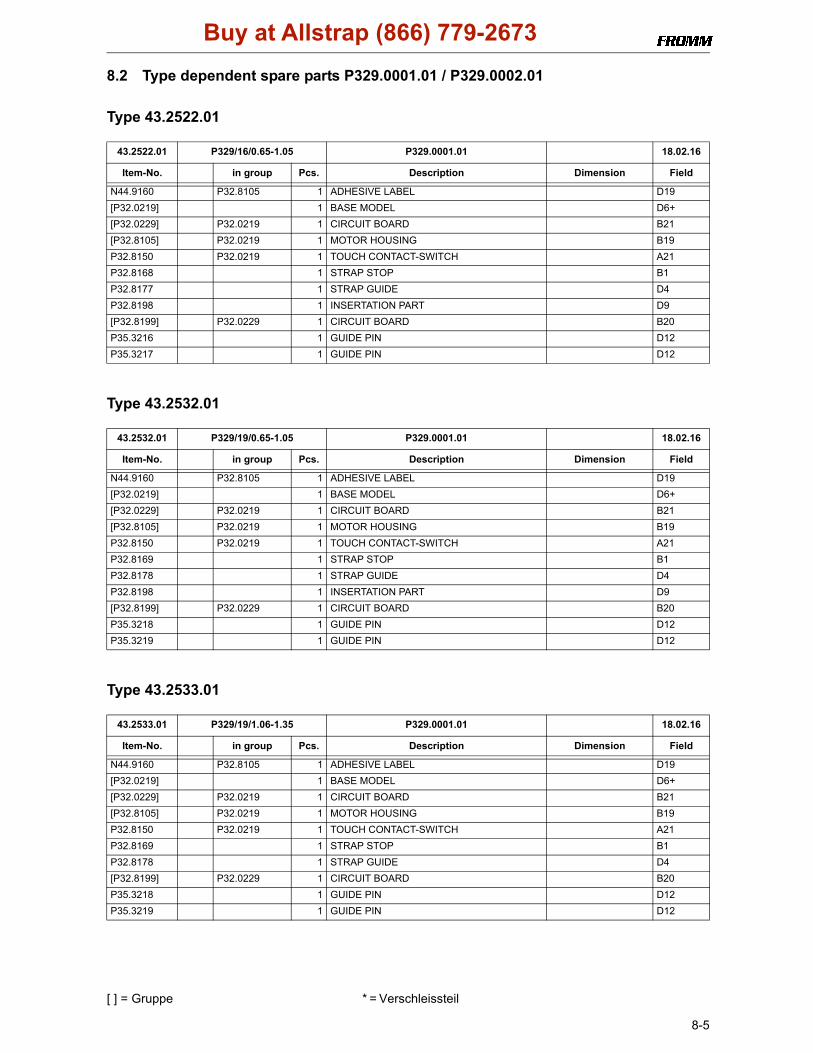
8-5
8.2 Type dependent spare parts P329.0001.01 / P329.0002.01
Type 43.2522.01
Type 43.2532.01
Type 43.2533.01
43.2522.01 P329/16/0.65-1.05 P329.0001.01 18.02.16
Item-No. in group Pcs. Description Dimension Field
N44.9160 P32.8105 1 ADHESIVE LABEL D19[P32.0219] 1 BASE MODEL D6+[P32.0229] P32.0219 1 CIRCUIT BOARD B21[P32.8105] P32.0219 1 MOTOR HOUSING B19P32.8150 P32.0219 1 TOUCH CONTACT-SWITCH A21P32.8168 1 STRAP STOP B1P32.8177 1 STRAP GUIDE D4P32.8198 1 INSERTATION PART D9[P32.8199] P32.0229 1 CIRCUIT BOARD B20P35.3216 1 GUIDE PIN D12P35.3217 1 GUIDE PIN D12
43.2532.01 P329/19/0.65-1.05 P329.0001.01 18.02.16
Item-No. in group Pcs. Description Dimension Field
N44.9160 P32.8105 1 ADHESIVE LABEL D19[P32.0219] 1 BASE MODEL D6+[P32.0229] P32.0219 1 CIRCUIT BOARD B21[P32.8105] P32.0219 1 MOTOR HOUSING B19P32.8150 P32.0219 1 TOUCH CONTACT-SWITCH A21P32.8169 1 STRAP STOP B1P32.8178 1 STRAP GUIDE D4P32.8198 1 INSERTATION PART D9[P32.8199] P32.0229 1 CIRCUIT BOARD B20P35.3218 1 GUIDE PIN D12P35.3219 1 GUIDE PIN D12
43.2533.01 P329/19/1.06-1.35 P329.0001.01 18.02.16
Item-No. in group Pcs. Description Dimension Field
N44.9160 P32.8105 1 ADHESIVE LABEL D19[P32.0219] 1 BASE MODEL D6+[P32.0229] P32.0219 1 CIRCUIT BOARD B21[P32.8105] P32.0219 1 MOTOR HOUSING B19P32.8150 P32.0219 1 TOUCH CONTACT-SWITCH A21P32.8169 1 STRAP STOP B1P32.8178 1 STRAP GUIDE D4[P32.8199] P32.0229 1 CIRCUIT BOARD B20P35.3218 1 GUIDE PIN D12P35.3219 1 GUIDE PIN D12
Buy at Allstrap (866) 779-2673

[ ] = Gruppe * = Verschleissteil
8-6
Type 43.2722.01
Type 43.2732.01
Type 43.2733.01
43.2722.01 P329/16/0.65-1.05/A P329.0002.01 18.02.16
Item-No. in group Pcs. Description Dimension Field
N44.9170 P32.8196 1 ADHESIVE LABEL D19[P32.0220] 1 BASE MODEL D6+[P32.0230] P32.0220 1 CIRCUIT BOARD B21P32.8133 P32.0220 1 PUSHER C23[P32.8154] P32.0220 1 TOUCH CONTACT-SWITCH A21P32.8168 1 STRAP STOP B1P32.8177 1 STRAP GUIDE D4[P32.8196] P32.0220 1 MOTOR HOUSING B19P32.8198 1 INSERTATION PART D9[P32.8199] P32.0230 1 CIRCUIT BOARD B20P35.3216 1 GUIDE PIN D12P35.3217 1 GUIDE PIN D12
43.2732.01 P329/19/0.65-1.05/A P329.0002.01 18.02.16
Item-No. in group Pcs. Description Dimension Field
N44.9170 P32.8196 1 ADHESIVE LABEL D19[P32.0220] 1 BASE MODEL D6+[P32.0230] P32.0220 1 CIRCUIT BOARD B21P32.8133 P32.0220 1 PUSHER C23[P32.8154] P32.0220 1 TOUCH CONTACT-SWITCH A21P32.8169 1 STRAP STOP B1P32.8178 1 STRAP GUIDE D4[P32.8196] P32.0220 1 MOTOR HOUSING B19P32.8198 1 INSERTATION PART D9[P32.8201] P32.0230 1 CIRCUIT BOARD B20P35.3218 1 GUIDE PIN D12P35.3219 1 GUIDE PIN D12
43.2733.01 P329/19/1.06-1.35/A P329.0002.01 18.02.16
Item-No. in group Pcs. Description Dimension Field
N44.9170 P32.8196 1 ADHESIVE LABEL D19[P32.0220] 1 BASE MODEL D6+[P32.0230] P32.0220 1 CIRCUIT BOARD B21P32.8133 P32.0220 1 PUSHER C23[P32.8154] P32.0220 1 TOUCH CONTACT-SWITCH A21P32.8169 1 STRAP STOP B1P32.8178 1 STRAP GUIDE D4[P32.8196] P32.0220 1 MOTOR HOUSING B19[P32.8201] P32.0230 1 CIRCUIT BOARD B20P35.3218 1 GUIDE PIN D12P35.3219 1 GUIDE PIN D12
Buy at Allstrap (866) 779-2673