p2000 series mid approved multifunction meter · the meter o˚ers high security with many useful...
TRANSCRIPT

P2000 SeriesMID Approved Multifunction Meter complete with RS 485 Modbus and Pulse OutputFeatures • Whole current 120 Amps or 5 amp current transformer operated• Communication by IR port IEC 62056-21• Communication by RS 485 Modbus (Autometers V6)• Pulse output IEC 62053-31 (kWh)• Accuracy – kWh Class 0.5s or 1 kWh Class C, A or B,
EC Directive 2004/22/EC [MID] kvarh Class 2 • Import/export kWh, kvarh and kVAh • Back light switches on when scrolling• Large size liquid crystal display with 11.9mm x 6mm Digits• Comprehensive tari� structure • Instrumentation indicated by OBIS code• Internal clock with battery back-up • Certi�ed 10 year product life • Extensive security data • High security, compact design • 12kV impulse withstand • Double insulated, polycarbonate case to DIN 43857 Part 2 and
Part 4 (except for top �xing centres) • IP53 in accordance with IEC 60529 • Connectability to Horizon full Monitoring and Invoicing package
Options• Load pro�ling• Range of communications media (External GSM/GPRS) • Terminal cover with cut-out • External battery for viewing display and reading
register data during power outages
Display
The P2000-D and P2000-T are con�gured to show the standard IEC 62056-61 OBIS identi�cation code which is explained on the terminal cover. See main image opposite. An optional battery can support the display and optical port reading during power down.
Tariff Structure 8 Time-of-use (TOU) registers 4 Maximum demand registers 40 Switching times (4 daily pro�les, each has max 10 changes)4 Seasons 4 Change of season dates 16 End of billing dates
The P2000-D and P2000-T o�er highly secure tari� metering with a variant to suit any commercial or light industrial application, with load pro�ling functions.
The meters are supplied with a large liquid crystal display with back light illumination so that the meter display can be read in virtually any lighting situations. Both the P2000-D and the P2000-T are pre programmed to display various electrical parameters as listed on the front of the terminal cover. All parameters are listed individually with the OBIS code.
Operation Pressing the blue buttons on the front of the meter will automatically change the display register to one of those listed on the front of the terminal cover, after a period of approximately three minutes the register will default back to 1:1.8.0. kWh
Top blue button Enables you to scroll back through the listCentre blue button Enables you to scroll forward in the listRed Button Enables you to reset the maximum demand
To read any of the listed parameters continually press the centre blue button and scroll through the list.
Communication from the meters can be obtained by three ways, Pulse output, pre set and �xed at 1 kwh per pulse, Optical port which can only be used with external hardware and software and the RS 485 Modbus (Autometers protocol V6 ) which is a wired connection. Using Modbus enables up to 127 meters to be read per Lan , Protocol for the Modbus can be obtained direct from Autometers Systems Ltd. Details for the pulse and Modbus connections are on the reverse side.
The meters are MID approved with appendix “B” and “D”.
Picture showing the P2000-T meter listing the standard set of pre-programmed measurement parameters.
Innovative Metering Solutions…
100mm
40mm
Autometers Systems Limited,4B Albany Road,Chorlton-cum-Hardy,Manchester.M21 0AW
Tel: +44 (0) 161 861 9056Fax: +44 (0) 161 881 3745
www.autometers.co.ukEmail: [email protected]
Product development is continuous and Autometers
Systems Ltd reserves the r ight to make alterations and
manufacture without notice. Products as delivered
may therefore di er from the descr iptions and
i l lustrations in this publication.
Publication No: P2000 01.01.2014
Data Storage load profile Up to 300 days of half hour data for one channel Programmable integration period Two channels of load pro�le storage for any measured quantity Instrumentation values
Security The meter o�ers high security with many useful security features. The meter stores all registration and con�guration data to non-volatile memory. The data is stored in non-volatile memory.
Energy measurement Import/export kWh, kvarh and kVAh energy
Communications Local: IEC 62056-21 Remote: Optional Serial Data Port Fast data collection of cumulative registers, historical data and load pro�ling using data stream mode
Low Voltage Terminals
System Connections 3 Element 3 phase, 4 wire 1 phase, 2 wire
2 Element 3 phase, 3 wire
Technical Data Current Range Direct connected 20-160A, 10-100A,
5-100A CT operated 5-10A*, 1-10A, 1-2A Voltage Range 220-240V* (L-N) or 220-240V (L-L) 380-415V (L-L)
105-127V (L-N) or 105-127V (L-L) 181-220V (L-L)Frequency 50 or 60Hz
Burden Voltage Circuits (230V) 0.8W, 1.3VA burden/phase [max] Current Circuits (DC) 4VA @ 100A/phase [max] Current Circuits (CT) 0.22VA per phase
Insulation 4kV RMS 50Hz Impulse Withstand 12kV 1.2/50μs 40 ohm source
Display LCD 11.9 x 6mm. High contrast, wide angle
Modbus Settings Baud Rate: 9600Parity type: EvenData Format: Floating PointF.P. Format: High word �rstModbus Address: 1-999Wire mode: Two
Front Optical Port 1200
Temperature -45° to +65° C (Operational range) -45° to +85° C (Storage) Humidity Annual mean 75% (95% for 30 days spread over
one year)
Pulse Width 100 ms �xed Wh/Pulse (120 Amp) 1 impulse/kWh (1000 watt hours/pulse �xed)Wh/Pulse (5 Amp) 1 impulse/kWh (1000 watt hours/pulse �xed)
Weight 940 grams
Speci�cations kWh Class 0.5s, 1 EN 62053-21/22 kWh Class A, B or C, EN 50470 (MID) kvarh Class 2 or 3 EN 62053-23
Case IP53 to IEC 60529
Push orange tab down to open terminal and release to lock conductor in terminal.
Innovative Metering Solutions…
Dimensions and Fixing Centres
263m
m
210m
m
175mm
150mm
83mm
Whole Current12
16 17 18 19 20 21 22 23 24 25* * 26 27
10987654321
L1L2L3N
MAINS
LOAD
+ -PV-kvarh
+ -PV-Im
port kW
h
+ -PV-E
xport kW
h
kWh
kvarhcom
mon (23-24)
RS485BA * Pulse output
PV-Import kWh to terminals 18 and19
P2P1
S1
S2
MAINS
1 2 3
L1V1
V2
EARTH
L2
L3
NNeutral
LOAD
L1
L2
L3
N
4 5 6 7 8 9
P2P1
S1
S2
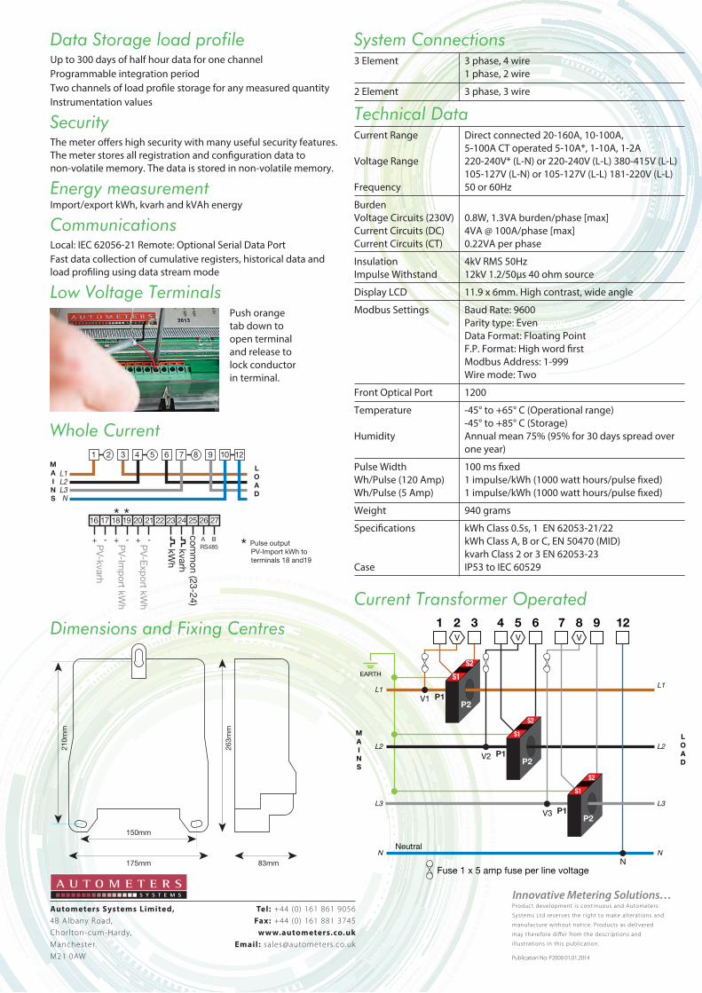
Fuse 1 x 5 amp fuse per line voltage
Current Transformer Operated
N
12
V3P2
P1
S1
S2
V V V