p1/p2-p5945gcx - cnet contentcdn.cnetcontent.com/f3/0d/f30d99aa-93a0-4487-9e64-fb514090351a.pdf ·...
TRANSCRIPT
P1/P2-P5945GCXASUS PC (Desktop Barebone)
User Guide

ii
Copyright © 2007 ASUSTeK COMPUTER INC. All Rights Reserved.No part of this manual, including the products and software described in it, may be reproduced, transmitted, transcribed, stored in a retrieval system, or translated into any language in any form or by any means, except documentation kept by the purchaser for backup purposes, without the express written permission of ASUSTeK COMPUTER INC. (“ASUS”).Product warranty or service will not be extended if: (1) the product is repaired, modified or altered, unless such repair, modification of alteration is authorized in writing by ASUS; or (2) the serial number of the product is defaced or missing.ASUS PROVIDES THIS MANUAL “AS IS” WITHOUT WARRANTY OF ANY KIND, EITHER EXPRESS OR IMPLIED, INCLUDING BUT NOT LIMITED TO THE IMPLIED WARRANTIES OR CONDITIONS OF MERCHANTABILITY OR FITNESS FOR A PARTICULAR PURPOSE. IN NO EVENT SHALL ASUS, ITS DIRECTORS, OFFICERS, EMPLOYEES OR AGENTS BE LIABLE FOR ANY INDIRECT, SPECIAL, INCIDENTAL, OR CONSEQUENTIAL DAMAGES (INCLUDING DAMAGES FOR LOSS OF PROFITS, LOSS OF BUSINESS, LOSS OF USE OR DATA, INTERRUPTION OF BUSINESS AND THE LIKE), EVEN IF ASUS HAS BEEN ADVISED OF THE POSSIBILITY OF SUCH DAMAGES ARISING FROM ANY DEFECT OR ERROR IN THIS MANUAL OR PRODUCT.SPECIFICATIONS AND INFORMATION CONTAINED IN THIS MANUAL ARE FURNISHED FOR INFORMATIONAL USE ONLY, AND ARE SUBJECT TO CHANGE AT ANY TIME WITHOUT NOTICE, AND SHOULD NOT BE CONSTRUED AS A COMMITMENT BY ASUS. ASUS ASSUMES NO RESPONSIBILITY OR LIABILITY FOR ANY ERRORS OR INACCURACIES THAT MAY APPEAR IN THIS MANUAL, INCLUDING THE PRODUCTS AND SOFTWARE DESCRIBED IN IT.Products and corporate names appearing in this manual may or may not be registered trademarks or copyrights of their respective companies, and are used only for identification or explanation and to the owners’ benefit, without intent to infringe.
E3532
First Edition December 2007
iii
Table of contentsNotices ......................................................................................................... viSafety information ..................................................................................... viiAbout this guide ....................................................................................... viiiSystem package contents ........................................................................... x
Chapter 1: System Introduction1.1 Welcome! ...................................................................................... 1-21.2 Front panel ................................................................................... 1-21.3 Rear panel ..................................................................................... 1-41.4 Internal components .................................................................... 1-6
Chapter 2: Basic Installation2.1 Preparation ................................................................................... 2-22.2 Before you proceed ..................................................................... 2-22.3 Removing the chassis cover ....................................................... 2-32.4 Removing the front panel assembly .......................................... 2-32.5 Central Processing Unit (CPU) ................................................... 2-4
2.5.1 Overview ......................................................................... 2-42.5.2 Removing the storage drive assembly ............................ 2-42.5.3 Installing CPU ................................................................. 2-42.5.4 Removing and Installing the CPU fan and heatsink assembly ......................................................................... 2-6
2.6 Installing a DIMM .......................................................................... 2-72.6.1 Memory configurations .................................................... 2-72.6.2 Installing a DDR2 DIMM ............................................... 2-102.6.3 Removing a DDR2 DIMM ............................................. 2-10
2.7 Expansion slots .......................................................................... 2-112.7.1 PCI slots .........................................................................2-112.7.2 Expansion card installation ............................................2-11
2.8 Installing an optical drive and reinstalling the storage drive assembly ..................................................................................... 2-142.9 Installing the foot stand ............................................................. 2-162.10 Reinstalling the chassis cover .................................................. 2-162.11 Reinstalling the front panel assembly ..................................... 2-16
Chapter 3: Starting up3.1 Installing an operating system ................................................... 3-2
iv
Table of contents3.2 Powering up .................................................................................. 3-23.3 Support CD information .............................................................. 3-2
3.3.1 Running the support CD ................................................. 3-33.3.2 Utilities menu .................................................................. 3-43.3.3 ASUS Contact information .............................................. 3-5
3.4 Software information ................................................................... 3-6ASUS PC Probe II .......................................................................... 3-6
Chapter 4: Motherboard Info4.1 Introduction .................................................................................. 4-24.2 Motherboard layout ...................................................................... 4-24.3 Jumpers ........................................................................................ 4-34.4 Connectors ................................................................................... 4-5
Chapter 5: BIOS Information5.1 Managing and updating your BIOS ............................................ 5-2
5.1.1 ASUS EZ Flash utility ...................................................... 5-35.1.2 AFUDOS utility ................................................................ 5-45.1.3 ASUS CrashFree BIOS 2 utility ...................................... 5-65.1.4 ASUS Update utility ........................................................ 5-8
5.2 BIOS setup program .................................................................. 5-115.2.1 BIOS menu screen ........................................................ 5-125.2.2 Menu bar ....................................................................... 5-125.2.3 Navigation keys ............................................................. 5-125.2.4 Menu items ................................................................... 5-135.2.5 Sub-menu items ............................................................ 5-135.2.6 Configuration fields ....................................................... 5-135.2.7 Pop-up window ............................................................. 5-135.2.8 Scroll bar ....................................................................... 5-135.2.9 General help ................................................................. 5-13
5.3 Main menu .................................................................................. 5-145.3.1 System Time ................................................................ 5-145.3.2 System Date ................................................................ 5-145.3.3 Primary IDE Master/Slave ............................................. 5-155.3.4 SATA1 ........................................................................... 5-165.3.5 IDE Configuration .......................................................... 5-175.3.6 System Information ....................................................... 5-18

v
Table of contents5.4 Advanced menu ......................................................................... 5-19
5.4.1 JumperFree Configuration ............................................ 5-195.4.2 USB Configuration ........................................................ 5-215.4.3 CPU Configuration ........................................................ 5-225.4.4 Chipset .......................................................................... 5-245.4.5 Onboard Devices Configuration .................................... 5-255.4.6 PCI PnP ........................................................................ 5-26
5.5 Power menu ................................................................................ 5-275.5.1 Suspend Mode ............................................................. 5-275.5.2 ACPI 2.0 Support ......................................................... 5-275.5.3 ACPI APIC Support ...................................................... 5-285.5.4 APM Configuration ........................................................ 5-285.5.5 Hardware Monitor ......................................................... 5-30
5.6 Boot menu .................................................................................. 5-315.6.1 Boot Device Priority ...................................................... 5-315.6.2 Boot Settings Configuration .......................................... 5-325.6.3 Security ......................................................................... 5-33
5.7 Exit menu .................................................................................... 5-35

vi
Notices
Federal Communications Commission StatementThis device complies with Part 15 of the FCC Rules. Operation is subject to the following two conditions:• This device may not cause harmful interference, and• This device must accept any interference received including interference that
may cause undesired operation.
This equipment has been tested and found to comply with the limits for a Class B digital device, pursuant to Part 15 of the FCC Rules. These limits are designed to provide reasonable protection against harmful interference in a residential installation. This equipment generates, uses and can radiate radio frequency energy and, if not installed and used in accordance with manufacturer’s instructions, may cause harmful interference to radio communications. However, there is no guarantee that interference will not occur in a particular installation. If this equipment does cause harmful interference to radio or television reception, which can be determined by turning the equipment off and on, the user is encouraged to try to correct the interference by one or more of the following measures:• Reorient or relocate the receiving antenna.• Increase the separation between the equipment and receiver.• Connect the equipment to an outlet on a circuit different from that to which the
receiver is connected.• Consult the dealer or an experienced radio/TV technician for help.
Canadian Department of Communications StatementThis digital apparatus does not exceed the Class B limits for radio noise emissions from digital apparatus set out in the Radio Interference Regulations of the Canadian Department of Communications.
This class B digital apparatus complies with Canadian ICES-003.
The use of shielded cables for connection of the monitor to the graphics card is required to assure compliance with FCC regulations. Changes or modifications to this unit not expressly approved by the party responsible for compliance could void the user’s authority to operate this equipment.

vii
Safety information
Electrical safety• To prevent electrical shock hazard, disconnect the power cable from the
electrical outlet before relocating the system.• When adding or removing devices to or from the system, ensure that the power
cables for the devices are unplugged before the signal cables are connected.• If the power supply is broken, do not try to fix it by yourself. Contact a qualified
service technician or your retailer.
Operation safety• Before installing devices into the system, carefully read all the documentation
that came with the package.• Before using the product, make sure all cables are correctly connected and the
power cables are not damaged. If you detect any damage, contact your dealer immediately.
• To avoid short circuits, keep paper clips, screws, and staples away from connectors, slots, sockets and circuitry.
• Avoid dust, humidity, and temperature extremes. Do not place the product in any area where it may become wet. Place the product on a stable surface.
• If you encounter technical problems with the product, contact a qualified service technician or your retailer.
Lithium-Ion Battery Warning
CAUTION: Danger of explosion if battery is incorrectly replaced. Replace only with the same or equivalent type recommended by the manufacturer. Dispose of used batteries according to the manufacturer’s instructions.
VORSICHT: Explosionsgetahr bei unsachgemäßen Austausch der Batterie. Ersatz nur durch denselben oder einem vom Hersteller empfohlenem ähnljchen Typ. Entsorgung gebrauchter Batterien nach Angaben des Herstellers.
LASER PRODUCT WARNING
CLASS 1 LASER PRODUCT
The symbol of the crossed out wheeled bin indicates that the product (electrical, electronic equipment, Mercury-containing button cell battery) should not be placed in municipal waste. Check local regulations for disposal of electronic products.

viii
About this guide
AudienceThis guide provides general information and installation instructions about ASUS P1/P2-P5945GCX barebone system. This guide is intended for experienced users and integrators with hardware knowledge of personal computers.
How this guide is organizedThis guide contains the following parts:
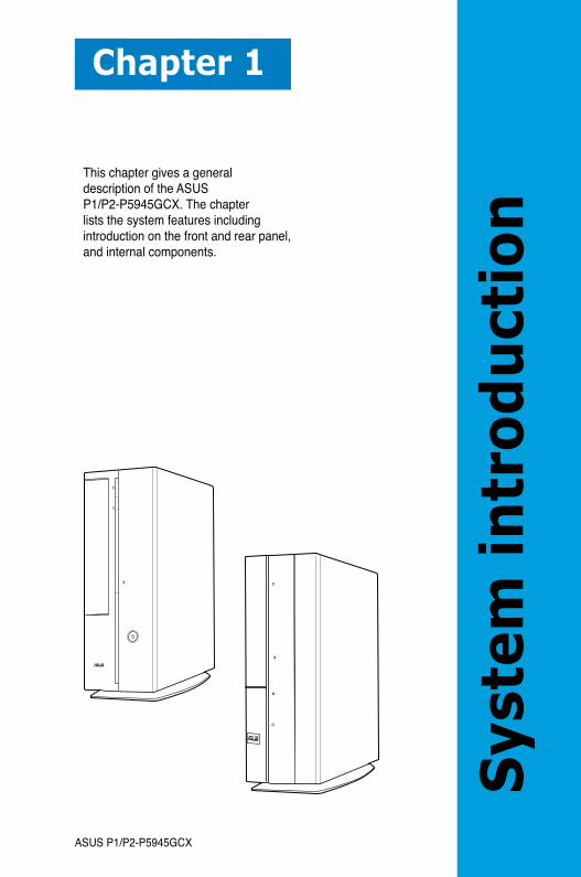
1. Chapter 1: System introductionThis chapter gives a general description of ASUS P1/P2-P5945GCX. The chapter lists the system features, including introduction on the front and rear panel, and internal components.
2. Chapter 2: Basic installationThis chapter provides step-by-step instructions on how to install components in the system.
3. Chapter 3: Starting upThis chapter helps you power up the system and install drivers and utilities from the support CD.
4. Chapter 4: Motherboard informationThis chapter gives information about the motherboard that comes with the system. This chapter includes the motherboard layout, jumper settings, and connector locations.
5. Chapter 5: BIOS informationThis chapter tells how to change system settings through the BIOS Setup menus and describes the BIOS parameters.
ix
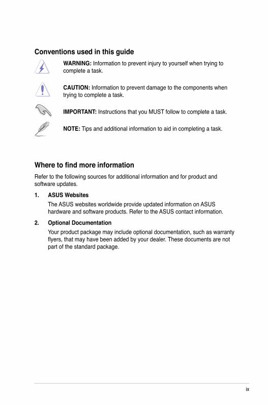
Conventions used in this guideWARNING: Information to prevent injury to yourself when trying to complete a task.
CAUTION: Information to prevent damage to the components when trying to complete a task.
IMPORTANT: Instructions that you MUST follow to complete a task.
NOTE: Tips and additional information to aid in completing a task.
Where to find more informationRefer to the following sources for additional information and for product and software updates.
1. ASUS WebsitesThe ASUS websites worldwide provide updated information on ASUS hardware and software products. Refer to the ASUS contact information.
2. Optional DocumentationYour product package may include optional documentation, such as warranty flyers, that may have been added by your dealer. These documents are not part of the standard package.
x
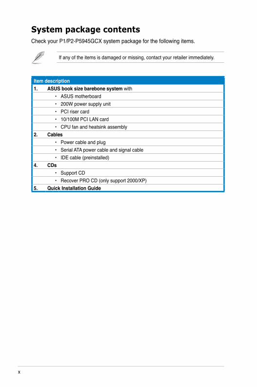
System package contentsCheck your P1/P2-P5945GCX system package for the following items.
If any of the items is damaged or missing, contact your retailer immediately.
Item description1. ASUS book size barebone system with
• ASUS motherboard• 200W power supply unit• PCI riser card• 10/100M PCI LAN card• CPU fan and heatsink assembly
2. Cables• Power cable and plug• Serial ATA power cable and signal cable• IDE cable (preinstalled)
4. CDs• Support CD• Recover PRO CD (only support 2000/XP)
5. Quick Installation Guide
ASUS P1/P2-P5945GCX
Chapter 1
Sys
tem
in
tro
du
ctio
n
This chapter gives a general description of the ASUS P1/P2-P5945GCX. The chapter lists the system features including introduction on the front and rear panel, and internal components.
1-2 Chapter 1: System introduction
1.1 Welcome!Thank you for choosing the ASUS P1/P2-P5945GCX!
The ASUS P1/P2-P5945GCX is an all-in-one barebone system with a versatile home entertainment feature.
The system comes in a stylish mini-tower casing and powered by the ASUS motherboard that supports the Intel® Pentium® D, Intel® Pentium® 4, Intel® Conroe® or Intel® Celeron® processor in the 775-land package.
The system supports up to 4 GB of system memory using DDR2-667/533/400 DIMMs, high-resolution graphics via integrated graphics controller, Serial ATA, USB 2.0, and 8-channel audio features the system takes you ahead in the world of power computing.
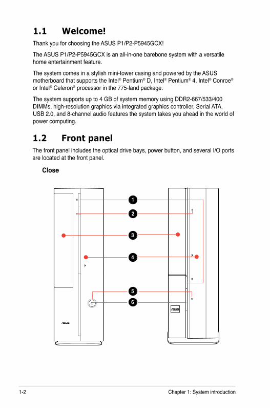
1.2 Front panel The front panel includes the optical drive bays, power button, and several I/O ports are located at the front panel.
Close
1
3
5
6
4
2
1-3ASUS P1/P2-P5945GCX
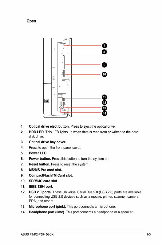
Open
1. Optical drive eject button. Press to eject the optical drive.2. HDD LED. This LED lights up when data is read from or written to the hard
disk drive. 3. Optical drive bay cover. 4. Press to open the front panel cover.5. Power LED. 6. Power button. Press this button to turn the system on.7. Reset button. Press to reset the system.8. MS/MS Pro card slot.9. CompactFlashTM Card slot.10. SD/MMC card slot.11. IEEE 1394 port.12. USB 2.0 ports. These Universal Serial Bus 2.0 (USB 2.0) ports are available
for connecting USB 2.0 devices such as a mouse, printer, scanner, camera, PDA, and others.
13. Microphone port (pink). This port connects a microphone.14. Headphone port (lime). This port connects a headphone or a speaker.
121314
9
10
11
8
7

1-4 Chapter 1: System introduction
1.3 Rear panelThe system rear panel includes the power connector and several I/O ports that allow convenient connection of devices.
1. Power connector2. Voltage selector. This switch allows you to adjust the system input voltage
according to the voltage supply in your area. If the voltage supply in your area is 100-127V, set this switch to 115V. If the voltage supply in your area is 200-240V, set this switch to 230V.
3. Center/Sub (yellow orange). This port connects the center/subwoofer speakers.
4. Surr-Side (black). This port connects the side speakers in an 8-channel audio configuration.
5. Surr-Rear (grey). This port connects the rear speakers on a 4-channel, 6-channel, or 8-channel audio configuration.
6. Line In port (light blue). This port connects the tape, CD, DVD player, or other audio sources.
7. Line Out port (lime). This port connects a headphone or a speaker. In 4-channel and 6-channel configuration, the function of this port becomes Front Speaker Out.
8. Microphone port (pink). This port connects a microphone.9. PS/2 mouse port. This green 6-pin connector is for a PS/2 mouse.10. PS/2 keyboard port. This purple 6-pin connector is for a
PS/2 keyboard.
SPDIF-O
KB/MS
12
45
6
3
1011
12
78
9
1413
15
1617
Setting the switch to 115V in a 230V environment or 230V in a 115 environment will seriously damage the system!

1-5ASUS P1/P2-P5945GCX
11. LAN (RJ-45) port. This port allows 10/100M connection to a Local Area Network (LAN) through a network hub.
12. USB 2.0 ports 1, 2, 3 and 4. These 4-pin Universal Serial Bus (USB) ports are available for connecting USB 2.0 devices.
13. SPDIF Out port. This port connects an external audio output device via an optical S/PDIF cable.
14. VGA port. This 15-pin port is for a VGA monitor or orther VGA-compatible devices.
15. DVI port. This port is for any DVI-D compatible device. DVI-D can’t be converted to output RGB Signal to CRT and isn’t compatible with DVI-I.
16. Serial port. This 9-pin COM1 port is for serial devices.17. PCI slot metal brackets
Refer to the audio configuration table below for the function of the audio ports in 2, 4, or 6-channel configuration.
Audio 2, 4, 6 or 8-channel configuration
Port Headset 2-channel
4-channel 6-channel 8-channel
Light Blue Line In Line In Line In Line InLime Line Out Front Speaker Out Front Speaker Out Front Speaker OutPink Mic In Mic In Mic In Mic InGray • Rear Speaker Out Rear Speaker Out Rear Speaker OutBlack • • • Side Speaker Out
Yellow Orange • • Center/Subwoofer Center/Subwoofer

1-6 Chapter 1: System introduction
1.4 Internal componentsThe illustration below is the internal view of the system when you remove the top cover. The installed components are labeled for your reference. Proceed to Chapter 2 for instructions on installing additional system components.
1. 5.25-inch optical drive and 3.5 inch hard disk drive cage
2. Front panel cover3. Power supply unit4. PCI card riser bracket (connected
to the motherboard PCI slot)
5. ASUS motherboard6. DIMM sockets7. LGA775 socket (under the CPU
fan and heatsink assembly)8. CPU fan and heatsink assembly
1
2
3
4
5
6
8
7

ASUS P1/P2-P5945GCX
Chapter 2
Bas
ic in
stal
lati
on
This chapter provides step-by-step instructions on how to install components in the system.
2-2 Chapter 2: Basic installation
2.1 PreparationBefore you proceed, make sure that you have all the components you plan to install in the system.
Basic components to install 1. Central Processing Unit (CPU) 2. DDR2 Dual Inline Memory Module (DIMM) 3. Expansion card(s) 4. Hard disk drive 5. Optical drive
ToolPhillips (cross) screw driver
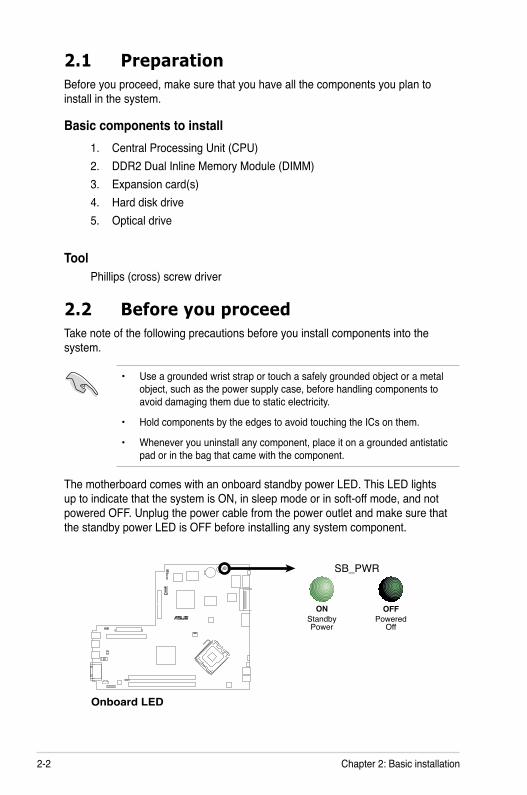
The motherboard comes with an onboard standby power LED. This LED lights up to indicate that the system is ON, in sleep mode or in soft-off mode, and not powered OFF. Unplug the power cable from the power outlet and make sure that the standby power LED is OFF before installing any system component.
• Use a grounded wrist strap or touch a safely grounded object or a metal object, such as the power supply case, before handling components to avoid damaging them due to static electricity.
• Hold components by the edges to avoid touching the ICs on them.
• Whenever you uninstall any component, place it on a grounded antistatic pad or in the bag that came with the component.
2.2 Before you proceedTake note of the following precautions before you install components into the system.
R
Onboard LED
SB_PWR
ONStandbyPower
OFFPowered
Off

2-3ASUS P1/P2-P5945GCX
2
To remove the front panel cover
1. Lift the front panel cover hooks outward.
2.3 Removing the chassis coverTo remove the chassis cover:1. Remove the cover screws. Keep
the screws for later use.
1 2
3
R
1
2. Pull the cover slightly toward the rear panel.
3. Lift the cover, then set aside.
2. Carefully remove the front panel cover, then set it aside.
2.4 Removing the front panel assembly

2-4 Chapter 2: Basic installation
2.5 Central Processing Unit (CPU)
2.5.1 OverviewThe motherboard comes with a surface mount LGA775 socket designed for the Intel® Pentium® 4 processor in the 775-land package.
2.5.3 Installing CPUTo install a CPU:
1. Locate the CPU socket on the motherboard.
Before installing the CPU, make sure that the socket box is facing towards you and the load lever is on your left.
2.5.2 Removing the storage drive assembly1. Lay the system on its side, then locate and remove three storage drive
assembly screws. 2. Lift the storage drive assembly, then set aside.
2
1
1
1
• Check your motherboard to make sure that the PnP cap is on the CPU socket and the socket contacts are not bent. Contact your retailer immediately if the PnP cap is missing, or if you see any damage to the PnP cap/socket contacts/motherboard components. ASUS will shoulder the cost of repair only if the damage is shipment/transit-related.
• Keep the cap after installing the motherboard. ASUS will process Return Merchandise Authorization (RMA) requests only if the motherboard comes with the cap on the LGA775 socket.
• The product warranty does not cover damage to the socket contacts resulting from incorrect CPU installation/removal, or misplacement/loss/incorrect removal of the PnP cap.

2-5ASUS P1/P2-P5945GCX
To prevent damage to the socket pins, do not remove the PnP cap unless you are installing a CPU.
2. Press the load lever with your thumb (A), then move it to the left (B) until it is released from the retention tab.
3. Lift the load lever in the direction of the arrow to a 135º angle.
A
B
Load lever
Retention tab
4. Lift the load plate with your thumb and forefinger to a 100º angle (4A), then push the PnP cap from the load plate window to remove (4B).
5. Position the CPU over the socket, making sure that the gold triangle is on the bottom-left corner of the socket then fit the socket alignment key into the CPU notch. Gold
triangle mark
Alignment key
CPU notch
Load platePnP cap
4A
4B
3
6. Close the load plate (A), then push the load lever (B) until it snaps into the retention tab.
A
B

2-6 Chapter 2: Basic installation
2.5.4 Removing and Installing the CPU fan and heatsink assemblyThe system package includes a proprietary CPU fan and heatsink assembly to ensure optimum thermal condition and performance.
DO NOT replace the proprietary CPU fan and heatsink with other models!
Refer to the figure below for the location of the CPU fan connector on the motherboard.
R
CPU FAN Connector
CPU_FAN
GN
D+1
2VTa
chom
eter
3. Lift the CPU fan and heatsink assembly, then set aside.
1. Disconnect the CPU fan cable.2. Loosen the CPU fan and heatsink
assembly screws with a screw driver.
Locate the CPU fan and heatsink assembly and secure it with the four screws, then reconnect the CPU fan cable to the CPU fan connector on the motherboard.
To reinstall the CPU fan and heatsink assembly:
To remove the CPU fan and heatsink assembly:
Do not forget to connect the CPU fan connector! Hardware monitoring errors can occur if you fail to plug this connector.
2 3
2-7ASUS P1/P2-P5945GCX
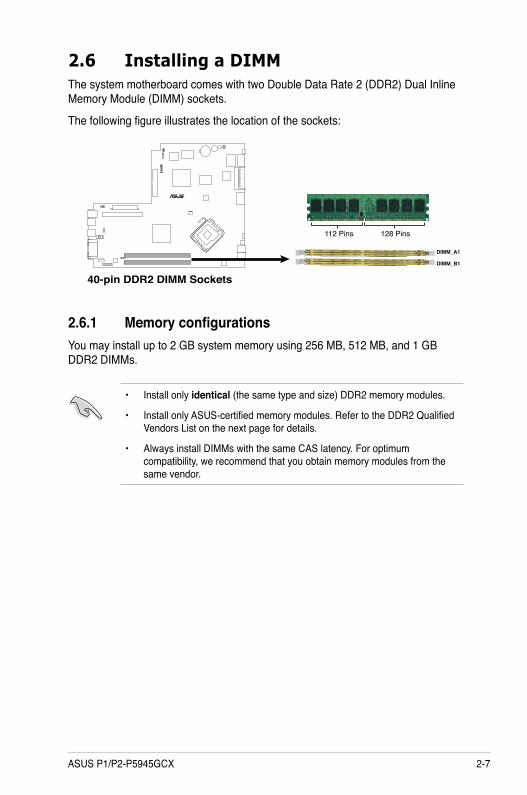
2.6 Installing a DIMMThe system motherboard comes with two Double Data Rate 2 (DDR2) Dual Inline Memory Module (DIMM) sockets.
The following figure illustrates the location of the sockets:
• Install only identical (the same type and size) DDR2 memory modules.
• Install only ASUS-certified memory modules. Refer to the DDR2 Qualified Vendors List on the next page for details.
• Always install DIMMs with the same CAS latency. For optimum compatibility, we recommend that you obtain memory modules from the same vendor.
2.6.1 Memory configurationsYou may install up to 2 GB system memory using 256 MB, 512 MB, and 1 GB DDR2 DIMMs.
R
40-pin DDR2 DIMM SocketsDIMM_B1
DIMM_A1
128 Pins112 Pins
2-8 Chapter 2: Basic installation
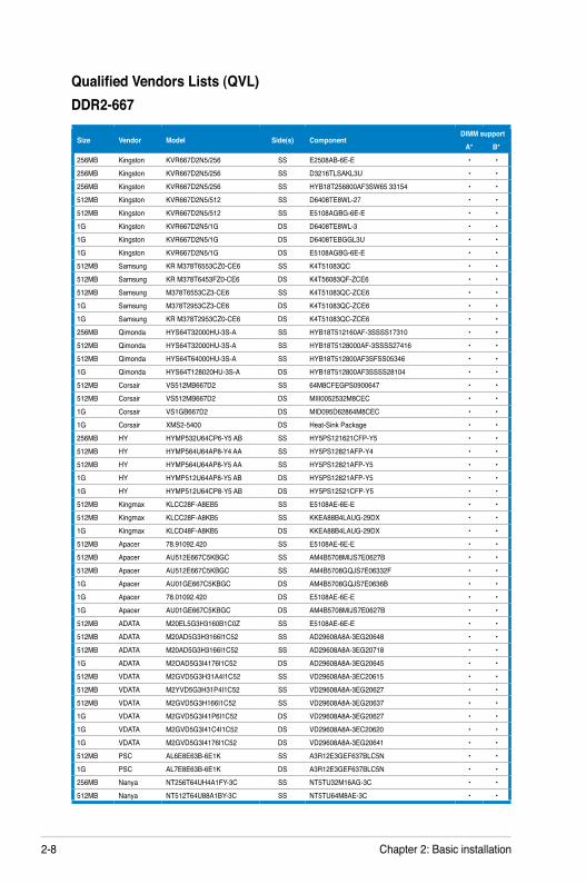
Qualified Vendors Lists (QVL)DDR2-667
Size Vendor Model Side(s) ComponentDIMM support
A* B*256MB Kingston KVR667D2N5/256 SS E2508AB-6E-E • •256MB Kingston KVR667D2N5/256 SS D3216TLSAKL3U • •256MB Kingston KVR667D2N5/256 SS HYB18T256800AF3SW65 33154 • •512MB Kingston KVR667D2N5/512 SS D6408TE8WL-27 • •512MB Kingston KVR667D2N5/512 SS E5108AGBG-6E-E • •1G Kingston KVR667D2N5/1G DS D6408TE8WL-3 • •1G Kingston KVR667D2N5/1G DS D6408TEBGGL3U • •1G Kingston KVR667D2N5/1G DS E5108AGBG-6E-E • •512MB Samsung KR M378T6553CZ0-CE6 SS K4T51083QC • •512MB Samsung KR M378T6453FZ0-CE6 DS K4T56083QF-ZCE6 • •512MB Samsung M378T6553CZ3-CE6 SS K4T51083QC-ZCE6 • •1G Samsung M378T2953CZ3-CE6 DS K4T51083QC-ZCE6 • •1G Samsung KR M378T2953CZ0-CE6 DS K4T51083QC-ZCE6 • •256MB Qimonda HYS64T32000HU-3S-A SS HYB18T512160AF-3SSSS17310 • •512MB Qimonda HYS64T32000HU-3S-A SS HYB18T5128000AF-3SSSS27416 • •512MB Qimonda HYS64T64000HU-3S-A SS HYB18T512800AF3SFSS05346 • •1G Qimonda HYS64T128020HU-3S-A DS HYB18T512800AF3SSSS28104 • •512MB Corsair VS512MB667D2 SS 64M8CFEGPS0900647 • •512MB Corsair VS512MB667D2 DS MIII0052532M8CEC • •1G Corsair VS1GB667D2 DS MID095D62864M8CEC • •1G Corsair XMS2-5400 DS Heat-Sink Package • •256MB HY HYMP532U64CP6-Y5 AB SS HY5PS121621CFP-Y5 • •512MB HY HYMP564U64AP8-Y4 AA SS HY5PS12821AFP-Y4 • •512MB HY HYMP564U64AP8-Y5 AA SS HY5PS12821AFP-Y5 • •1G HY HYMP512U64AP8-Y5 AB DS HY5PS12821AFP-Y5 • •1G HY HYMP512U64CP8-Y5 AB DS HY5PS12521CFP-Y5 • •512MB Kingmax KLCC28F-A8EB5 SS E5108AE-6E-E • •512MB Kingmax KLCC28F-A8KB5 SS KKEA88B4LAUG-29DX • •1G Kingmax KLCD48F-A8KB5 DS KKEA88B4LAUG-29DX • •512MB Apacer 78.91092.420 SS E5108AE-6E-E • •512MB Apacer AU512E667C5KBGC SS AM4B5708MIJS7E0627B • •512MB Apacer AU512E667C5KBGC SS AM4B5708GQJS7E06332F • •1G Apacer AU01GE667C5KBGC DS AM4B5708GQJS7E0636B • •1G Apacer 78.01092.420 DS E5108AE-6E-E • •1G Apacer AU01GE667C5KBGC DS AM4B5708MIJS7E0627B • •512MB ADATA M20EL5G3H3160B1C0Z SS E5108AE-6E-E • •512MB ADATA M20AD5G3H3166I1C52 SS AD29608A8A-3EG20648 • •512MB ADATA M20AD5G3H3166I1C52 SS AD29608A8A-3EG20718 • •1G ADATA M2OAD5G3I4176I1C52 DS AD29608A8A-3EG20645 • •512MB VDATA M2GVD5G3H31A4I1C52 SS VD29608A8A-3EC20615 • •512MB VDATA M2YVD5G3H31P4I1C52 SS VD29608A8A-3EG20627 • •512MB VDATA M2GVD5G3H166I1C52 SS VD29608A8A-3EG20637 • •1G VDATA M2GVD5G3I41P6I1C52 DS VD29608A8A-3EG20627 • •1G VDATA M2GVD5G3I41C4I1C52 DS VD29608A8A-3EC20620 • •1G VDATA M2GVD5G3I4176I1C52 DS VD29608A8A-3EG20641 • •512MB PSC AL6E8E63B-6E1K SS A3R12E3GEF637BLC5N • •1G PSC AL7E8E63B-6E1K DS A3R12E3GEF637BLC5N • •256MB Nanya NT256T64UH4A1FY-3C SS NT5TU32M16AG-3C • •512MB Nanya NT512T64U88A1BY-3C SS NT5TU64M8AE-3C • •

2-9ASUS P1/P2-P5945GCX
DDR2-533
Side(s): SS - Single-sided DS - Double-sidedCL: CAS Latency
DIMM support:A - Supports one module inserted into either slot, in Single-channel
memory configuration.B - Supports one pair of modules inserted into both slots as one pair of
Dual-channel memory configuration.
Size Vendor Model Side(s) ComponentDIMM
supportA* B*
1G Kingston KVR533D2N4/1G DS D6408TE7BL-37 • •256MB Samsung M378T3253FG0-CD5 SS K4T56083QF-GCD5 • •512MB Samsung M378T6553BG0-CD5 SS K4T51083QB-GCD5 • •256MB Qimonda HYS64T32000HU-3.7-A SS HYB18T512160AF-3.7AFSS31270 • •512MB Qimonda HYS64T64000GU-3.7-A SS HYB18T512800AC37SSS11511 • •512MB Qimonda HYS64T64000HU-3.7-A SS HYB18T512800AF37SSS12079 • •512MB Qimonda HYS64T64000HU-3.7-A SS HYB18T512800AF37FSS29334 • •256MB HY HYMP532U64CP6-C4 AB SS HY5PS121621CFP-C4 • •1G HY HYMP512U64CP8-C4 AB DS HY5PS12821CFP-C4 • •512MB Micron MT 16HTF6464AG-53EB2 DS D9BOM • •512MB Micron MT 16HTF6464AG-53EB2 DS Z9BQT • •1G Micron MT 16HTF12864AY-53EA1 DS D9CRZ • •512MB Corsair VS512MB533D2 DS MIII0052532M8CEC • •512MB Corsair VS512MB533D2 DS MI110052532M8CEC • •1G Corsair VS1GB533D2 DS 64M8CFEGQIB0900718 • •512MB Elpida EBE51UD8ABFA-5C-E SS E5108AB-5C-E • •512MB Kingmax KLBC28F-A8KB4 SS KKEA88B4IAK-37 • •256MB Kingmax KLBB68F-36EP4 SS E5116AB-5C-E • •512MB Kingmax KLBC28F-A8EB4 SS E5108AE-5C-E • •
512MB ADATA M2OAD2G3H3166I1B52 SS AD29608A8A-37DG20719 • •2G ADATA M20AD2H3J4170I1B53 DS AD20908A8A-37DG30721 • •
2-10 Chapter 2: Basic installation
Unlocked retaining clip
1
DDR2 DIMM notch
1
2
Locked Retaining Clip
DDR2 DIMM notch
1
1
2
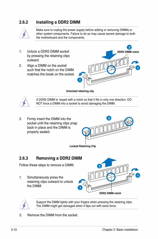
2.6.3 Removing a DDR2 DIMMFollow these steps to remove a DIMM.
1. Simultaneously press the retaining clips outward to unlock the DIMM.
2. Remove the DIMM from the socket.
Support the DIMM lightly with your fingers when pressing the retaining clips. The DIMM might get damaged when it flips out with extra force.
2.6.2 Installing a DDR2 DIMM
3. Firmly insert the DIMM into the socket until the retaining clips snap back in place and the DIMM is properly seated.
1. Unlock a DDR2 DIMM socket by pressing the retaining clips outward.
2. Align a DIMM on the socket such that the notch on the DIMM matches the break on the socket.
Make sure to unplug the power supply before adding or removing DIMMs or other system components. Failure to do so may cause severe damage to both the motherboard and the components.
A DDR2 DIMM is keyed with a notch so that it fits in only one direction. DO NOT force a DIMM into a socket to avoid damaging the DIMM.
3

2-11ASUS P1/P2-P5945GCX
2.7 Expansion slotsThis motherboard provides two PCI expansion slots, which locate on the PCI raiser card that is connected to its slot on the motherboard.
2.7.1 PCI slotsThe PCI slots support cards such as a LAN card, SCSI card, USB card, another cards that comply with PCI specifications.
2.7.2 Expansion card installation
Before installing an expansion card, read the documentation that came with it and make the necessary hardware settings for the card.
Make sure to unplug the power cord before adding or removing expansion cards. Failure to do so may cause you physical injury and damage motherboard components.
1. Lift the PCI riser card assembly to remove.
The length of the PCI card should be less than 150mm on the system.

2-12 Chapter 2: Basic installation
2. Remove the metal cover opposite the slot that you intend to use.
3. Insert the card connector to the slot, then press the card firmly until it fits in place. Secure the card with a screw.
4. Reinstall the PCI riser card assembly. Make sure that the riser card connector sits properly on the motherboard PCI slot.

2-13ASUS P1/P2-P5945GCX
* These IRQs are usually available for ISA or PCI devices.
When using PCI cards on shared slots, ensure that the drivers support “Share IRQ” or that the cards do not need IRQ assignments. Otherwise, conflicts will arise between the two PCI groups, making the system unstable and the card inoperable.
Standard interrupt assignments
IRQ Standard Function0 System Timer1 Keyboard Controller2 Re-direct to IRQ#93 IRQ holder for PCI steering*4 Communications Port (COM1)*5 IRQ holder for PCI steering*6 Floppy Disk Controller7 Printer Port (LPT1)*8 System CMOS/Real Time Clock9 IRQ holder for PCI steering*10 IRQ holder for PCI steering*11 IRQ holder for PCI steering*12 PS/2 Compatible Mouse Port*13 Numeric Data Processor14 Primary IDE Channel15 Secondary IDE Channel
IRQ assignments for this motherboard
A B C D E F G HPCI slot 1 shared — — — — — — —PCI slot 2 — shared — — — — — —Onboard USB controller 1 — — — — shared — — —Onboard USB controller 2 — shared — — — — — —Onboard USB controller 3 — — shared — — — — —Onboard USB controller 4 — — — shared — — — —Onboard USB 2.0 controller — — — — shared — — —Onboard IDE port — — shared — — — — —Onboard HD audio — — — shared — — — —Onboard LAN shared — — — — — — —

2-14 Chapter 2: Basic installation
2.8 Installing an optical drive and reinstalling the storage drive assemblyRefer to the instructions in this section if you wish to install a new optical drive.
Follow these steps to install an optical drive:
1. Turn the storage drive assembly upside down with the 3.5-inch bay on top of the 5.25-inch bay.
2. Insert the optical drive upside down to the 5.25-inch bay, then secure it with two screws on both sides.
3. Turn the storage drive assembly, insert the hard disk drive upside down to the 3.5-inch bay, then secure it with two screws on both sides.
2
3

2-15ASUS P1/P2-P5945GCX
Before reinstalling the storage drive assembly, connect the IDE/SATA and power plugs to the IDE/SATA and power connectors at the back of the drives.
1. Connect the black plug of the IDE cable to the optical drive, then the gray plug to the hard disk drive. If you have the SATA HDD, connect the SATA cable to the SATA HD.
2. Connect the 4-pin power plugs to the power connectors at the back of the drives.
3. Install the storage drive assembly to the chassis.
4. Secure the storage drive assembly with three screws.
Follow these steps to reinstall the storage drive assembly:
R
3
R
4

2-16 Chapter 2: Basic installation
2.9 Installing the foot stand
To install the foot stand:
1. Match the foot stand hooks to the holes on the chassis.
2. Pull the foot stand to the direction of the arrow until the lock clicks in place.
To remove the foot stand, lift the lock, then slightly push the foot stand to the direction of the rear panel until it disengages from the chassis.
2.10 Reinstalling the chassis coverTo reinstall the front panel cover, refer to the section 2.3 Removing the chassis cover and follow the instructions in reverse.
2.11 Reinstalling the front panel assemblyTo reinstall the front panel cover, refer to the section 2.4 Removing the front panel assembly and follow the instructions in reverse.
ASUS P1/P2-P5945GCX
Chapter 3
Sta
rtin
g u
p
This chapter helps you power up the system and install drivers and utilities from the support CD.

3-2 Chapter 3: Starting up
3.1 Installing an operating systemThe barebone system supports Windows® 2000/XP operating systems (OS). Always install the latest OS version and corresponding updates so you can maximize the features of your hardware.
3.3 Support CD informationThe support CD that came with the system contains useful software and several utility drivers that enhance the system features.
3.2 Powering upPress the system power button ( ) to enter the OS.
Press to turn ON the system
Because motherboard settings and hardware options vary, use the setup procedures presented in this chapter for general reference only. Refer to your OS documentation for more information.
• Screen display and driver options may not be the same for different operating system versions.
• The contents of the support CD are subject to change at any time without notice. Visit the ASUS website for updates.
3-3ASUS P1/P2-P5945GCX
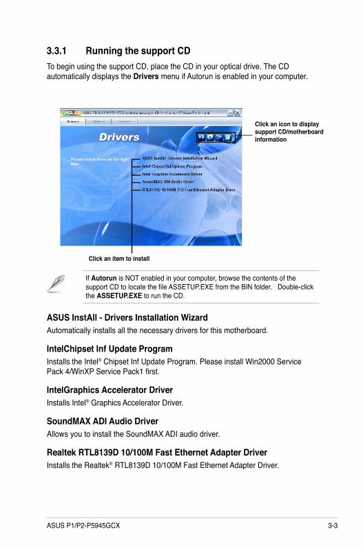
3.3.1 Running the support CDTo begin using the support CD, place the CD in your optical drive. The CD automatically displays the Drivers menu if Autorun is enabled in your computer.
If Autorun is NOT enabled in your computer, browse the contents of the support CD to locate the file ASSETUP.EXE from the BIN folder. Double-click the ASSETUP.EXE to run the CD.
Click an item to install
Click an icon to display support CD/motherboard information
ASUS InstAll - Drivers Installation WizardAutomatically installs all the necessary drivers for this motherboard.
IntelChipset Inf Update ProgramInstalls the Intel® Chipset Inf Update Program. Please install Win2000 Service Pack 4/WinXP Service Pack1 first.
IntelGraphics Accelerator DriverInstalls Intel® Graphics Accelerator Driver.
SoundMAX ADI Audio DriverAllows you to install the SoundMAX ADI audio driver.
Realtek RTL8139D 10/100M Fast Ethernet Adapter DriverInstalls the Realtek® RTL8139D 10/100M Fast Ethernet Adapter Driver.
3-4 Chapter 3: Starting up
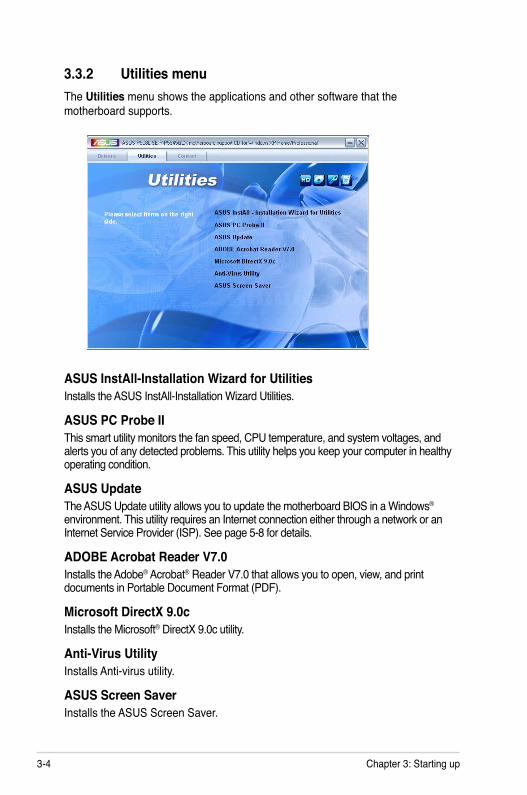
3.3.2 Utilities menuThe Utilities menu shows the applications and other software that the motherboard supports.
ASUS InstAll-Installation Wizard for UtilitiesInstalls the ASUS InstAll-Installation Wizard Utilities.
ASUS PC Probe IIThis smart utility monitors the fan speed, CPU temperature, and system voltages, and alerts you of any detected problems. This utility helps you keep your computer in healthy operating condition.
ASUS Update The ASUS Update utility allows you to update the motherboard BIOS in a Windows® environment. This utility requires an Internet connection either through a network or an Internet Service Provider (ISP). See page 5-8 for details.
ADOBE Acrobat Reader V7.0Installs the Adobe® Acrobat® Reader V7.0 that allows you to open, view, and print documents in Portable Document Format (PDF).
Microsoft DirectX 9.0cInstalls the Microsoft® DirectX 9.0c utility.
Anti-Virus UtilityInstalls Anti-virus utility.
ASUS Screen SaverInstalls the ASUS Screen Saver.

3-5ASUS P1/P2-P5945GCX
3.3.3 ASUS Contact informationClick the Contact tab to display the ASUS contact information. You can also find this information on the inside front cover of this user guide.

3-6 Chapter 3: Starting up
2. Click the Utilities tab, then click ASUS PC Probe II.
3. Follow the screen instructions to complete installation.
Launching PC Probe IIYou can launch the PC Probe II right after installation or anytime from the Windows® desktop.
To launch the PC Probe II from the Windows® desktop, click Start > All Programs > ASUS > PC Probe II. The PC Probe II main window appears.
After launching the application, the PC Probe II icon appears in the Windows® taskbar. Click this icon to close or restore the application.
Using PC Probe IIMain windowThe PC Probe II main window allows you to view the current status of your system and change the utility configuration. By default, the main window displays the Preference section. You can close or restore the Preference section by clicking on the triangle on the main window right handle.
3.4 Software informationMost of the applications in the support CD have wizards that will conveniently guide you through the installation. View the online help or readme file that came with the software for more information.
ASUS PC Probe IIPC Probe II is a utility that monitors the computer’s vital components and alerts you of any problem with these components. PC Probe II senses fan rotations, CPU temperature, and system voltages, among others. PC Probe II is software-based, allowing you to start monitoring your computer the moment you turn it on. With this utility, you are assured that your computer is always at a healthy operating condition.
Installing PC Probe IITo install PC Probe II on your computer:
1. Place the support CD to the optical drive. The Drivers installation tab appears if your computer has an enabled Autorun feature.
Click to close the Preference panel
If Autorun is not enabled in your computer, browse the contents of the support CD to locate the setup.exe file from the ASUS PC Probe II folder. Double-click the setup.exe file to start installation.
3-7ASUS P1/P2-P5945GCX
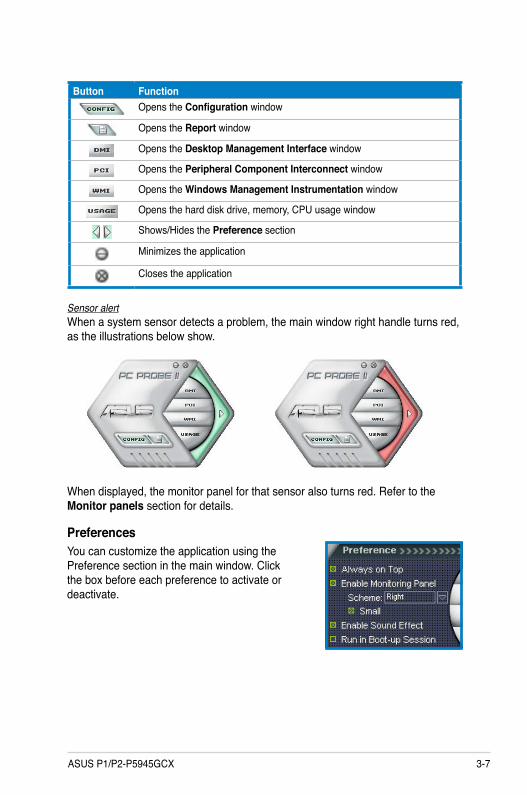
Button FunctionOpens the Configuration window
Opens the Report window
Opens the Desktop Management Interface window
Opens the Peripheral Component Interconnect window
Opens the Windows Management Instrumentation window
Opens the hard disk drive, memory, CPU usage window
Shows/Hides the Preference section
Minimizes the application
Closes the application
Sensor alertWhen a system sensor detects a problem, the main window right handle turns red, as the illustrations below show.
When displayed, the monitor panel for that sensor also turns red. Refer to the Monitor panels section for details.
PreferencesYou can customize the application using the Preference section in the main window. Click the box before each preference to activate or deactivate.

3-8 Chapter 3: Starting up
Hardware monitor panelsThe hardware monitor panels display the current value of a system sensor such as fan rotation, CPU temperature, and voltages.
The hardware monitor panels come in two display modes: hexagonal (large) and rectangular (small). When you check the Enable Monitoring Panel option from the Preference section, the monitor panels appear on your computer’s desktop.
Changing the monitor panels positionTo change the position of the monitor panels on the desktop, click the arrow down button of the Scheme options, then select another position from the list box. Click OK when finished.Moving the monitor panelsAll monitor panels move together using a magnetic effect. If you want to detach a monitor panel from the group, click the horseshoe magnet icon. You can now move or reposition the panel independently.Adjusting the sensor threshold value You can adjust the sensor threshold value in the monitor panel by clicking the arrow buttons. You can also adjust the threshold values using the Config window.
You cannot adjust the sensor threshold values in a small monitoring panel.
Large display
Small display
Click to increase value
Click to decrease
value

3-9ASUS P1/P2-P5945GCX
Monitoring sensor alertThe monitor panel turns red when a component value exceeds or is lower than the threshold value. Refer to the illustrations below.
Large display
Small display
WMI browserClick to display the WMI (Windows Management Instrumentation) browser. This browser displays various Windows® management information. Click an item from the left panel to display on the right panel. Click the plus sign (+) before WMI Information to display the available information.
You can enlarge or reduce the browser size by dragging the bottom right corner of the browser.
DMI browserClick to display the DMI (Desktop Management Interface) browser. This browser displays various desktop and system information. Click the plus sign (+) before DMI Information to display the available information.

3-10 Chapter 3: Starting up
PCI browserClick to display the PCI (Peripheral Component Interconnect) browser. This browser provides information on the PCI devices installed on your system. Click the plus sign (+) before the PCI Information item to display available information.
UsageThe Usage browser displays real-time information on the CPU, hard disk drive space, and memory usage. Click to display the Usage browser.CPU usageThe CPU tab displays real-time CPU usage in line graph representation. If the CPU has an enabled Hyper-Threading, two separate line graphs display the operation of the two logical processors.
Hard disk drive space usageThe Hard Disk tab displays the used and available hard disk drive space. The left panel of the tab lists all logical drives. Click a hard disk drive to display the information on the right panel. The pie chart at the bottom of the window represents the used (blue) and the available HDD space.
3-11ASUS P1/P2-P5945GCX
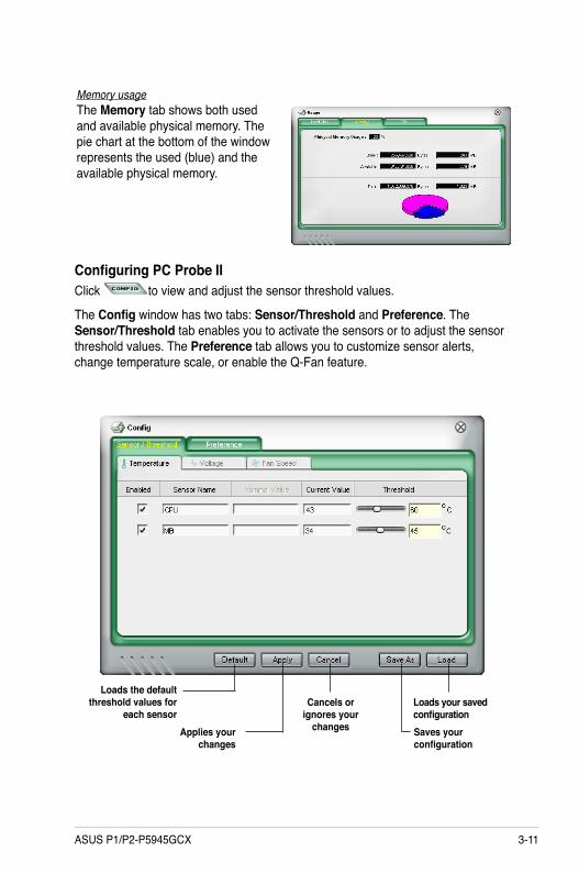
Memory usageThe Memory tab shows both used and available physical memory. The pie chart at the bottom of the window represents the used (blue) and the available physical memory.
Configuring PC Probe IIClick to view and adjust the sensor threshold values.
The Config window has two tabs: Sensor/Threshold and Preference. The Sensor/Threshold tab enables you to activate the sensors or to adjust the sensor threshold values. The Preference tab allows you to customize sensor alerts, change temperature scale, or enable the Q-Fan feature.
Loads the default threshold values for
each sensorApplies your
changes
Cancels or ignores your
changes
Loads your saved configurationSaves your configuration

3-12 Chapter 3: Starting up

ASUS P1/P2-P5945GCX
Chapter 4
Mo
ther
bo
ard
in
fo
This chapter gives information about the motherboard that comes with the system. This chapter includes the motherboard layout, jumper settings, and connector locations.
4-2 Chapter 4: Motherboard info
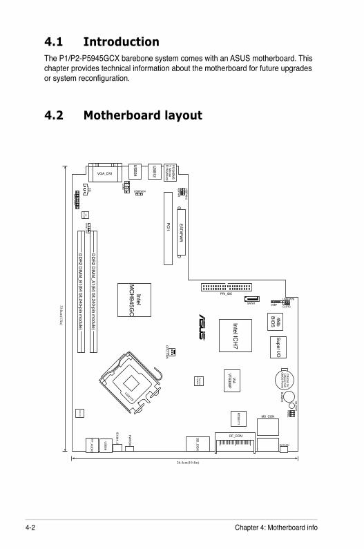
4.1 IntroductionThe P1/P2-P5945GCX barebone system comes with an ASUS motherboard. This chapter provides technical information about the motherboard for future upgrades or system reconfiguration.
4.2 Motherboard layout
33.0cm(13in)
LGA775
CR
2032 3VLithium
Cell
CM
OS Pow
erBUZZER SB_PW
RPANELMS_CON
RSTCON
RTS5111
VIA VT6308P
CF_CON
26.4cm(10.4in)
SD_C
ON
IE1394_2
PWR
SWUSB56
FP_AUD
IO(64
b it,240 -pinm
odule)D
DR
2 DIM
M_A1(6 4
bit,240 -pinm
odule)D
DR
2 DIM
M_B1
R
Intel ICH
7
Intel M
CH
945GC
4Mb
BIOS
Super I/O
CLRTC
USBPW78
USB7
PRI_IDE
SATA1
EATXPWR
PCI1
KBPWR
USBPW12
USBPW34PS/2KBM
ST: M
ouseB: Keyboard
USB12
USB34VGA_DVI
SPDIF_OUT
CO
M1
BACK_AU
DIO
ADI
AD1988B
CPU
_FAN
ATX12V
CD
Cypress
CY28551

4-3ASUS P1/P2-P5945GCX
4.3 Jumpers1. Clear RTC RAM (CLRTC)
This jumper allows you to clear the Real Time Clock (RTC) RAM in CMOS. You can clear the CMOS memory of date, time, and system setup parameters by erasing the CMOS RTC RAM data. The onboard button cell battery powers the RAM data in the CMOS, which includes the system setup information such as system passwords.
To erase the RTC RAM:
1. Turn OFF the computer and unplug the power cord. 2. Remove the battery.
3. Move the jumper cap from pins 1-2 (default) to pins 2-3. Keep the cap on pins 2-3 for about 5-10 seconds, then move the cap back to pins 1-2.
4. Re-install the battery. 5. Plug the power cord and turn ON the computer. 6. Hold down the <Del> key during the boot process and enter BIOS
setup to re-enter data.
Except when clearing the RTC RAM, never remove the cap on CLRTC jumper default position. Removing the cap will cause system boot failure.
R
Clear RTC RAM
CLRTC
Normal Clear RTC(Default)
12 2
3
4-4 Chapter 4: Motherboard info
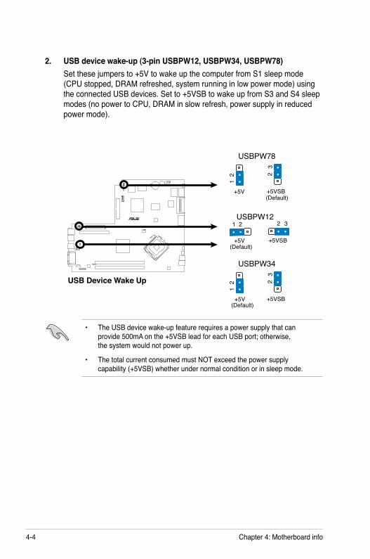
2. USB device wake-up (3-pin USBPW12, USBPW34, USBPW78)Set these jumpers to +5V to wake up the computer from S1 sleep mode (CPU stopped, DRAM refreshed, system running in low power mode) using the connected USB devices. Set to +5VSB to wake up from S3 and S4 sleep modes (no power to CPU, DRAM in slow refresh, power supply in reduced power mode).
• The USB device wake-up feature requires a power supply that can provide 500mA on the +5VSB lead for each USB port; otherwise, the system would not power up.
• The total current consumed must NOT exceed the power supply capability (+5VSB) whether under normal condition or in sleep mode.
R
USB Device Wake Up3
221
USBPW78
+5V(Default)+5VSB
322
1
USBPW34
+5V(Default)
+5VSB
3221USBPW12
+5V(Default)
+5VSB
4-5ASUS P1/P2-P5945GCX
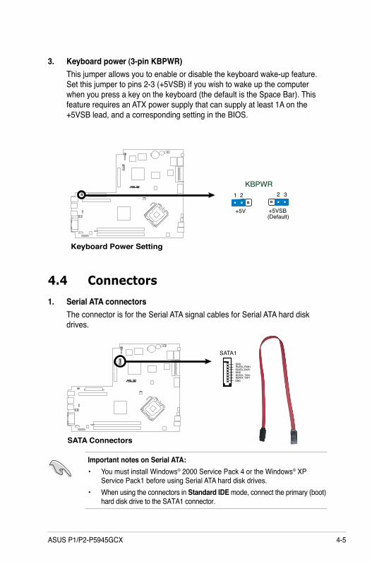
3. Keyboard power (3-pin KBPWR)This jumper allows you to enable or disable the keyboard wake-up feature. Set this jumper to pins 2-3 (+5VSB) if you wish to wake up the computer when you press a key on the keyboard (the default is the Space Bar). This feature requires an ATX power supply that can supply at least 1A on the +5VSB lead, and a corresponding setting in the BIOS.
R
Keyboard Power Setting
KBPWR3221
+5V(Default)+5VSB
4.4 Connectors
1. Serial ATA connectorsThe connector is for the Serial ATA signal cables for Serial ATA hard disk drives.
Important notes on Serial ATA:• You must install Windows® 2000 Service Pack 4 or the Windows® XP
Service Pack1 before using Serial ATA hard disk drives.• When using the connectors in Standard IDE mode, connect the primary (boot)
hard disk drive to the SATA1 connector.
R
SATA Connectors
GNDRSATA_TXP1RSATA_TXN1GNDRSATA_RXP1RSATA_RXN1GND
SATA1

4-6 Chapter 4: Motherboard info
2 IDE connectors (40-1 pin PRI_IDE)The onboard IDE connectors are for Ultra DMA 100/66/33 signal cable(s). There are three connectors on each Ultra DMA 100/66/33 signal cable: blue, black, and gray. Connect the blue connector to the motherboard’s IDE connector, then select one of the following modes to configure your device(s).
• Pin 20 on the IDE connector is removed to match the covered hole on the Ultra DMA cable connector. This prevents incorrect insertion when you connect the IDE cable.
• Use the 80-conductor IDE cable for Ultra DMA 100/66/33 IDE devices.
If any device jumper is set as “Cable-Select”, make sure all other device jumpers have the same setting.
Drive jumper setting
Mode Cable of device(s)
Cable connector
Single device Cable-Select or Master
- Black
Two devices Cable-Select Master Slave
Black Gray
Master Slave
Master Slave
Black or gray
R
IDE Connector
NOTE: Orient the red markings(usually zigzag) on the IDribbon cable to PIN 1.
PRI_IDE
PIN
1
4-7ASUS P1/P2-P5945GCX
Never connect a 1394 cable to the USB connectors. Doing so will damage the motherboard!
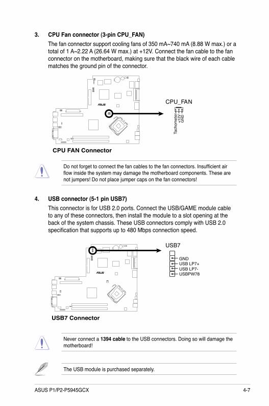
4. USB connector (5-1 pin USB7)This connector is for USB 2.0 ports. Connect the USB/GAME module cable to any of these connectors, then install the module to a slot opening at the back of the system chassis. These USB connectors comply with USB 2.0 specification that supports up to 480 Mbps connection speed.
The USB module is purchased separately.
3. CPU Fan connector (3-pin CPU_FAN)The fan connector support cooling fans of 350 mA~740 mA (8.88 W max.) or a total of 1 A~2.22 A (26.64 W max.) at +12V. Connect the fan cable to the fan connector on the motherboard, making sure that the black wire of each cable matches the ground pin of the connector.
Do not forget to connect the fan cables to the fan connectors. Insufficient air flow inside the system may damage the motherboard components. These are not jumpers! Do not place jumper caps on the fan connectors!
R
CPU FAN Connector
CPU_FAN
GN
D+1
2VTa
chom
eter
R
USB7 Connector
USB7
GNDUSB LP7+USB LP7-USBPW78
4-8 Chapter 4: Motherboard info
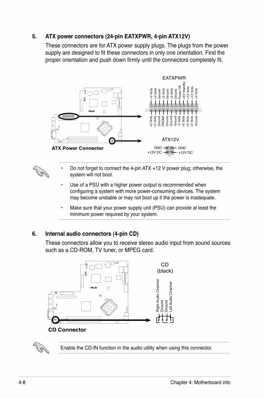
5. ATX power connectors (24-pin EATXPWR, 4-pin ATX12V)These connectors are for ATX power supply plugs. The plugs from the power supply are designed to fit these connectors in only one orientation. Find the proper orientation and push down firmly until the connectors completely fit.
R
ATX Power Connector +12V DC
GND+12V DCGND
ATX12V
+3 V
olts
+3 V
olts
Gro
und
+5 V
olts
+5 V
olts
Gro
und
Gro
und
Pow
er O
K+5
V St
andb
y+1
2 Vo
lts
-5 V
olts
+5 V
olts
+3 V
olts
-12
Volts
Gro
und
Gro
und
Gro
und
PSO
N#
Gro
und
+5 V
olts
+12
Volts
+3 V
olts
+5 V
olts
Gro
und
EATXPWR
• Do not forget to connect the 4-pin ATX +12 V power plug; otherwise, the system will not boot.
• Use of a PSU with a higher power output is recommended when configuring a system with more power-consuming devices. The system may become unstable or may not boot up if the power is inadequate.
• Make sure that your power supply unit (PSU) can provide at least the minimum power required by your system.
6. Internal audio connectors (4-pin CD)These connectors allow you to receive stereo audio input from sound sources such as a CD-ROM, TV tuner, or MPEG card.
Enable the CD-IN function in the audio utility when using this connector.
R
CD Connector
CD(black)
Rig
ht A
udio
Cha
nnel
Left
Audi
o C
hann
elG
roun
dG
roun
d
4-9ASUS P1/P2-P5945GCX
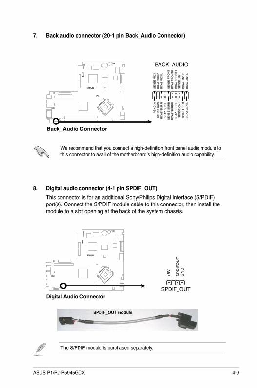
7. Back audio connector (20-1 pin Back_Audio Connector)
We recommend that you connect a high-definition front panel audio module to this connector to avail of the motherboard’s high-definition audio capability.
8. Digital audio connector (4-1 pin SPDIF_OUT)This connector is for an additional Sony/Philips Digital Interface (S/PDIF) port(s). Connect the S/PDIF module cable to this connector, then install the module to a slot opening at the back of the system chassis.
The S/PDIF module is purchased separately.
R
Digital Audio Connector
+5V
SPD
IFO
UT
GN
D
SPDIF_OUT
R
Back_Audio Connector
BACK_AUDIO
BCAZ
LIN
1 L
BCAZ
LIN
1 R
SEN
SE L
IN1
BCAZ
FR
ON
T L
BCAZ
FR
ON
TRSE
NSE
FR
ON
T
BCAZ
MIC
1LBC
AZ M
IC1R
SEN
SE M
IC1
BCAZ
CEN
LBC
AZ L
EF R
SEN
SE C
N1
BCAZ
SU
RBL
BCAZ
SU
RBR
SEN
SE S
UR
BBC
AZ S
UR
LBC
AZ S
UR
RSE
NSE
SU
RAG
ND
_A
4-10 Chapter 4: Motherboard info
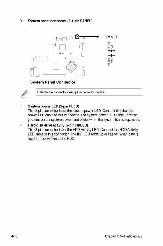
9. System panel connector (6-1 pin PANEL)
Refer to the connector description below for details.
• System power LED (2-pin PLED) This 2-pin connector is for the system power LED. Connect the chassis power LED cable to this connector. The system power LED lights up when you turn on the system power, and blinks when the system is in sleep mode.
• Hard disk drive activity (2-pin HDLED) This 2-pin connector is for the HDD Activity LED. Connect the HDD Activity LED cable to this connector. The IDE LED lights up or flashes when data is read from or written to the HDD.
R
System Panel Connector
NEL
HD_LED+
PLED+
HD_LED-
PLED-
PA
1
Chapter 5
BIO
S s
etu
p
This chapter tells how to change system settings through the BIOS Setup menus and describes the BIOS parameters.
5-2 Chapter 5: BIOS setup5-2
5.1 Managing and updating your BIOSThe following utilities allow you to manage and update the motherboard Basic Input/Output System (BIOS) setup.
1. ASUS EZ Flash: Updates the BIOS using a floppy disk, or the motherboard support CD during POST.
2. ASUS AFUDOS: Updates the BIOS using a bootable floppy disk in DOS mode.
3. ASUS CrashFree BIOS 2: Updates the BIOS using a bootable floppy disk or the motherboard support CD when the BIOS file fails or gets corrupted.
4. ASUS Update: Updates the BIOS in Windows® environment.
Refer to the corresponding sections for details on these utilities.
Save a copy of the original motherboard BIOS file to a bootable floppy disk in case you need to restore the BIOS in the future. Copy the original motherboard BIOS using the ASUS Update or AFUDOS utilities.

5-3ASUS P1/P2-P5945GCX
5.1.1 ASUS EZ Flash utilityThe ASUS EZ Flash feature allows you to update the BIOS without having to go through the long process of booting from a floppy disk and using a DOS-based utility. The EZ Flash utility is built-in the BIOS chip so it is accessible by pressing <Alt> + <F2> during the Power-On Self Tests (POST).
To update the BIOS using EZ Flash:
1. Visit the ASUS website (www.asus.com) to download the latest BIOS file for the motherboard and rename the same to P5945GCX.ROM.
2. Save the BIOS file to a floppy disk, then restart the system.3. Press <Alt> + <F2> during POST to display the following.
EZFlash starting BIOS updateChecking for floppy...
4. Insert the floppy disk that contains the BIOS file to the floppy disk drive. When the correct BIOS file is found, EZ Flash performs the BIOS update process and automatically reboots the system when done.
EZFlash starting BIOS updateChecking for floppy...Floppy found!Reading file “P5945GCX.rom”. Completed.Start erasing.......|Start programming...|Flashed successfully. Rebooting.
• Do not shut down or reset the system while updating the BIOS to prevent system boot failure!
• A “Floppy not found!” error message appears if there is no floppy disk in the drive. A “P5945GCX.ROM not found!” error message appears if the correct BIOS file is not found in the floppy disk. Make sure that you rename the BIOS file to P5945GCX.ROM.

5-4 Chapter 5: BIOS setup
5.1.2 AFUDOS utilityThe AFUDOS utility allows you to update the BIOS file in DOS environment using a bootable floppy disk with the updated BIOS file. This utility also allows you to copy the current BIOS file that you can use as backup when the BIOS fails or gets corrupted during the updating process.
Copying the current BIOSTo copy the current BIOS file using the AFUDOS utility:
1. Copy the AFUDOS utility (afudos.exe) from the motherboard support CD to the bootable floppy disk you created earlier.
2. Boot the system in DOS mode, then at the prompt type:
afudos /o[filename]
where the [filename] is any user-assigned filename not more than eight alphanumeric characters for the main filename and three alphanumeric characters for the extension name.
• Make sure that the floppy disk is not write-protected and has at least 600 KB free space to save the file.
• The succeeding BIOS screens are for reference only. The actual BIOS screen displays may not be exactly the same as shown.
Main filename Extension name
A:\>afudos /oOLDBIOS1.ROM
The utility returns to the DOS prompt after copying the current BIOS file.
3. Press <Enter>. The utility copies the current BIOS file to the floppy disk.
A:\>afudos /oOLDBIOS1.ROMAMI Firmware Update Utility - Version 1.19 V2.26(06.08.28BB))Copyright (C) 2003 American Megatrends, Inc. All rights reserved. Reading flash ..... doneA:\>

5-5ASUS P1/P2-P5945GCX
2. Copy the AFUDOS utility (afudos.exe) from the motherboard support CD to the bootable floppy disk you created earlier.
3. Boot the system in DOS mode, then at the prompt type:
afudos /i[filename]
where [filename] is the latest or the original BIOS file on the bootable floppy disk.
Updating the BIOS fileTo update the BIOS file using the AFUDOS utility:
1. Visit the ASUS website (www.asus.com) and download the latest BIOS file for the motherboard. Save the BIOS file to a bootable floppy disk.
4. The utility reads the file and starts updating the BIOS.
Do not shut down or reset the system while updating the BIOS to prevent system boot failure!
Write the BIOS filename on a piece of paper. You need to type the exact BIOS filename at the DOS prompt.
A:\>afudos /iP5945GCX.ROMAMI Firmware Update Utility - Version 1.19 V2.26(06.08.28BB))Copyright (C) 2003 American Megatrends, Inc. All rights reserved. WARNING!! Do not turn off power during flash BIOS Reading file ..... done Reading flash .... done Search bootblock version Advance Check........ Erasing flash .... done Writing flash .... 0x0008CC00 (9%)
A:\>afudos /iP5945GCX.ROM

5-6 Chapter 5: BIOS setup
5. The utility returns to the DOS prompt after the BIOS update process is completed. Reboot the system from the hard disk drive.
A:\>afudos /iP5945GCX.ROMAMI Firmware Update Utility - Version 1.19 V2.26(06.08.28BB)Copyright (C) 2003 American Megatrends, Inc. All rights reserved. WARNING!! Do not turn off power during flash BIOS Reading file ..... done Reading flash .... done Search bootblock version Advance Check......... Erasing flash ..... done Writing flash ..... done Verifying flash ... done
Please restart your computer
A:\>
5.1.3 ASUS CrashFree BIOS 2 utilityThe ASUS CrashFree BIOS 2 is an auto recovery tool that allows you to restore the BIOS file when it fails or gets corrupted during the updating process. You can update a corrupted BIOS file using the motherboard support CD or the floppy disk that contains the updated BIOS file.
Recovering the BIOS from a floppy diskTo recover the BIOS from a floppy disk:
1. Turn on the system.2. Insert the floppy disk with the original or updated BIOS file to the floppy disk
drive.
• Prepare the motherboard support CD or the floppy disk containing the updated motherboard BIOS before using this utility.
• Make sure that you rename the original or updated BIOS file in the floppy disk to P5945GCX.ROM.

5-7ASUS P1/P2-P5945GCX
Recovering the BIOS from the support CDTo recover the BIOS from the support CD:
1. Remove any floppy disk from the floppy disk drive, then turn on the system.2. Insert the support CD to the optical drive.3. The utility displays the following message and automatically checks the
floppy disk for the original or updated BIOS file.
Bad BIOS checksum. Starting BIOS recovery...Checking for floppy...Floppy not found!Checking for CD-ROM...CD-ROM found!Reading file “P5945GCX.ROM”. Completed.Start flashing...
When no floppy disk is found, the utility automatically checks the optical drive for the original or updated BIOS file. The utility then updates the corrupted BIOS file.
Bad BIOS checksum. Starting BIOS recovery...Checking for floppy...
Bad BIOS checksum. Starting BIOS recovery...Checking for floppy...
4. Restart the system after the utility completes the updating process.
Bad BIOS checksum. Starting BIOS recovery...Checking for floppy...Floppy found!Reading file “P5945GCX.ROM”. Completed.Start flashing...
When found, the utility reads the BIOS file and starts flashing the corrupted BIOS file.
DO NOT shut down or reset the system while updating the BIOS! Doing so can cause system boot failure!
3. The utility displays the following message and automatically checks the floppy disk for the original or updated BIOS file.
5-8 Chapter 5: BIOS setup
The recovered BIOS may not be the latest BIOS version for this motherboard. Visit the ASUS website (www.asus.com) to download the latest BIOS file.
4. Restart the system after the utility completes the updating process.
DO NOT shut down or reset the system while updating the BIOS! Doing so can cause system boot failure!
Installing ASUS UpdateTo install ASUS Update:
1. Place the support CD in the optical drive. The Drivers menu appears. 2. Click the Utilities tab, then click ASUS Update. See page 3-4 for the Utilities
screen menu.3. The ASUS Update utility is copied to your system.
5.1.4 ASUS Update utilityThe ASUS Update is a utility that allows you to manage, save, and update the motherboard BIOS in Windows® environment. The ASUS Update utility allows you to:
• Save the current BIOS file • Download the latest BIOS file from the Internet • Update the BIOS from an updated BIOS file • Update the BIOS directly from the Internet, and • View the BIOS version information.
This utility is available in the support CD that comes with the motherboard package.
ASUS Update requires an Internet connection either through a network or an Internet Service Provider (ISP).
Quit all Windows® applications before you update the BIOS using this utility.

5-9ASUS P1/P2-P5945GCX
3. Select the ASUS FTP site nearest you to avoid network traffic, or click Auto Select. Click Next.
Updating the BIOS through the InternetTo update the BIOS through the Internet:
1. Launch the ASUS Update utility from the Windows® desktop by clicking Start > Programs > ASUS > ASUSUpdate > ASUSUpdate. The ASUS Update main window appears.
2. Select Update BIOS from the Internet option from the drop-down menu, then click Next.

5-10 Chapter 5: BIOS setup
Updating the BIOS through a BIOS fileTo update the BIOS through a BIOS file:
1. Launch the ASUS Update utility from the Windows® desktop by clicking Start > Programs > ASUS > ASUSUpdate > ASUSUpdate. The ASUS Update main window appears.
2. Select Update BIOS from a file option from the drop-down menu, then click Next.
4. From the FTP site, select the BIOS version that you wish to download. Click Next.
5. Follow the screen instructions to complete the update process.
The ASUS Update utility is capable of updating itself through the Internet. Always update the utility to avail all its features.
3. Locate the BIOS file from the Open window, then click Open.
4. Follow the screen instructions to complete the update process.
5-11ASUS P1/P2-P5945GCX
5.2 BIOS setup programThis motherboard supports a programmable Low-Pin Count (LPC) chip that you can update using the provided utility described in section “5.1 Managing and updating your BIOS.”
Use the BIOS Setup program when you are installing a motherboard, reconfiguring your system, or prompted to“Run Setup.” This section explains how to configure your system using this utility.
Even if you are not prompted to use the Setup program, you can change the configuration of your computer in the future. For example, you can enable the security password feature or change the power management settings. This requires you to reconfigure your system using the BIOS Setup program so that the computer can recognize these changes and record them in the CMOS RAM of the LPC chip.
The LPC chip on the motherboard stores the Setup utility. When you start up the computer, the system provides you with the opportunity to run this program. Press <Del> during the Power-On Self-Test (POST) to enter the Setup utility. Otherwise, POST continues with its test routines.
If you wish to enter Setup after POST, reboot the system by doing any of the following procedures:
• Restart using the OS standard shut-down procedure.• Press <Ctrl>+<Alt>+<Del> simultaneously. • Press the reset button on the system chassis. • Press the power button to turn the system off then back on.
• The default BIOS settings for this motherboard apply for most conditions to ensure optimum performance. If the system becomes unstable after changing any BIOS settings, load the default settings to ensure system compatibility and stability. Select the Load Default Settings item under the Exit Menu. See section “5.7 Exit Menu.”
• The BIOS setup screens shown in this section are for reference purposes only, and may not exactly match what you see on your screen.
• Visit the ASUS website (www.asus.com) to download the latest BIOS file for this motherboard.
Using the power button, reset button, or the <Ctrl>+<Alt>+<Del> keys to force reset from a running operating system can cause damage to your data or system. We recommend to always shut-down the system properly from the operating system.
The Setup program is designed to make it as easy to use as possible. Being a menu-driven program, it lets you scroll through the various sub-menus and make your selections from the available options using the navigation keys.

5-12 Chapter 5: BIOS setup
5.2.2 Menu barThe menu bar on top of the screen has the following main items:
Main For changing the basic system configurationAdvanced For changing the advanced system settingsPower For changing the advanced power management (APM)
configurationBoot For changing the system boot configurationExit For selecting the exit options and loading default
settings
5.2.1 BIOS menu screen
To select an item on the menu bar, press the right or left arrow key on the keyboard until the desired item is highlighted.
5.2.3 Navigation keysAt the bottom right corner of a menu screen are the navigation keys for that particular menu. Use the navigation keys to select items in the menu and change the settings.
Use [ENTER], [TAB] or [SHIFT-TAB] to select a field.
Use [+] or [-] to configure the System time.
Navigation keys
General helpMenu bar
Sub-menu items
Configuration fieldsMenu items
Some of the navigation keys differ from one screen to another.
System Time [21:01:35] System Date [Fri 11/09/2007]
Primary IDE Master :[Not Detected] Primary IDE Slave :[Not Detected] SATA1 :[Not Detected] IDE Configuration
System Information
5-13ASUS P1/P2-P5945GCX
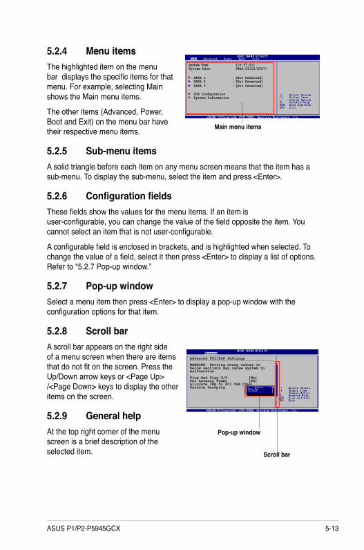
5.2.4 Menu itemsThe highlighted item on the menu bar displays the specific items for that menu. For example, selecting Main shows the Main menu items.
The other items (Advanced, Power, Boot and Exit) on the menu bar have their respective menu items.
5.2.5 Sub-menu itemsA solid triangle before each item on any menu screen means that the item has a sub-menu. To display the sub-menu, select the item and press <Enter>.
5.2.6 Configuration fieldsThese fields show the values for the menu items. If an item is user-configurable, you can change the value of the field opposite the item. You cannot select an item that is not user-configurable.
A configurable field is enclosed in brackets, and is highlighted when selected. To change the value of a field, select it then press <Enter> to display a list of options. Refer to “5.2.7 Pop-up window.”
5.2.7 Pop-up windowSelect a menu item then press <Enter> to display a pop-up window with the configuration options for that item.
5.2.8 Scroll barA scroll bar appears on the right side of a menu screen when there are items that do not fit on the screen. Press the Up/Down arrow keys or <Page Up> /<Page Down> keys to display the other items on the screen.
5.2.9 General helpAt the top right corner of the menu screen is a brief description of the selected item.
Main menu items
System Time [16:37:21] System Date [Wed,03/15/2007]
SATA 1 : [Not Detected] SATA 2 : [Not Detected] SATA 3 : [Not Detected]
IDE Configuration System Information
Advanced PCI/PnP Settings
WARNING: Setting wrong values in below sections may cause system to malfunction.
Plug And Play O/S [No]PCI Latency Timer [64]Allocate IRQ to PCI VGA [Yes]Palette Snooping
Scroll bar
Pop-up window

5-14 Chapter 5: BIOS setup
5.3 Main menuWhen you enter the BIOS Setup program, the Main menu screen appears, giving you an overview of the basic system information.
5.3.1 System Time [xx:xx:xx]Allows you to set the system time.
5.3.2 System Date [Day xx/xx/xxxx]Allows you to set the system date.
Refer to section “5.2.1 BIOS menu screen” for information on the menu screen items and how to navigate through them.
Use [ENTER], [TAB] or [SHIFT-TAB] to select a field.
Use [+] or [-] to configure the System time.
System Time [16:37:21] System Date [Fri,11/09/2007]
Primary IDE Master :[Not Detected] Primary IDE Slave :[Not Detected] SATA1 :[Not Detected] IDE Configuration
System Information
5-15ASUS P1/P2-P5945GCX
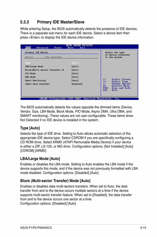
5.3.3 Primary IDE Master/SlaveWhile entering Setup, the BIOS automatically detects the presence of IDE devices. There is a separate sub-menu for each IDE device. Select a device item then press <Enter> to display the IDE device information.
The BIOS automatically detects the values opposite the dimmed items (Device, Vendor, Size, LBA Mode, Block Mode, PIO Mode, Async DMA, Ultra DMA, and SMART monitoring). These values are not user-configurable. These items show Not Detected if no IDE device is installed in the system.
Type [Auto]Selects the type of IDE drive. Setting to Auto allows automatic selection of the appropriate IDE device type. Select CDROM if you are specifically configuring a CD-ROM drive. Select ARMD (ATAPI Removable Media Device) if your device is either a ZIP, LS-120, or MO drive. Configuration options: [Not Installed] [Auto] [CDROM] [ARMD]
LBA/Large Mode [Auto]Enables or disables the LBA mode. Setting to Auto enables the LBA mode if the device supports this mode, and if the device was not previously formatted with LBA mode disabled. Configuration options: [Disabled] [Auto]
Block (Multi-sector Transfer) Mode [Auto]Enables or disables data multi-sectors transfers. When set to Auto, the data transfer from and to the device occurs multiple sectors at a time if the device supports multi-sector transfer feature. When set to [Disabled], the data transfer from and to the device occurs one sector at a time. Configuration options: [Disabled] [Auto]
Primary IDE Master
Device : Not Detected Type [Auto]LBA/Large Mode [Auto]Block(Multi-sector Transfer) M [Auto]PIO Mode [Auto]DMA Mode [Auto]Smart Monitoring [Auto]32Bit Data Transfer [Enabled]
Exit
Select the type of device connected to the system.
5-16 Chapter 5: BIOS setup
PIO Mode [Auto]Selects the PIO mode. Configuration options: [Auto] [0] [1] [2] [3] [4]
DMA Mode [Auto]Selects the DMA mode. Configuration options: [Auto]
SMART Monitoring [Auto]Sets the Smart Monitoring, Analysis, and Reporting Technology. Configuration options: [Auto] [Disabled] [Enabled]
32Bit Data Transfer [Enabled]Enables or disables 32-bit data transfer. Configuration options: [Disabled] [Enabled]
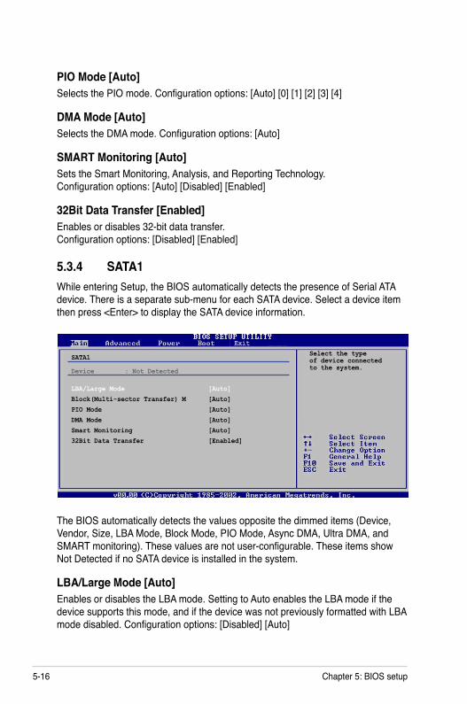
5.3.4 SATA1While entering Setup, the BIOS automatically detects the presence of Serial ATA device. There is a separate sub-menu for each SATA device. Select a device item then press <Enter> to display the SATA device information.
The BIOS automatically detects the values opposite the dimmed items (Device, Vendor, Size, LBA Mode, Block Mode, PIO Mode, Async DMA, Ultra DMA, and SMART monitoring). These values are not user-configurable. These items show Not Detected if no SATA device is installed in the system.
LBA/Large Mode [Auto]Enables or disables the LBA mode. Setting to Auto enables the LBA mode if the device supports this mode, and if the device was not previously formatted with LBA mode disabled. Configuration options: [Disabled] [Auto]
SATA1
Device : Not Detected LBA/Large Mode [Auto]Block(Multi-sector Transfer) M [Auto]PIO Mode [Auto]DMA Mode [Auto]Smart Monitoring [Auto]32Bit Data Transfer [Enabled]
ExitSelect the type of device connected to the system.

5-17ASUS P1/P2-P5945GCX
5.3.5 IDE ConfigurationThe items in this menu allow you to set or change the configurations for the IDE devices installed in the system. Select an item then press <Enter> if you want to configure the item.
IDE Configuration
Onboard IDE Operate Mode [Enhanced Mode] Enhanced Mode Support On [S-ATA]IDE Detect Time Out (Sec) [35]
Select the time out value for detecting ATA/ATAPI device)s).
Onboard IDE Operate Mode [Enhanced Mode]Disables or allows selection of the IDE operation mode depending on the operating system (OS) that you installed. Set to Enhanced Mode if you are using native OS, such as Windows® 2000/XP. Configuration options: [Disabled] [Compatible Mode] [Enhanced Mode]
Block (Multi-sector Transfer) Mode [Auto]Enables or disables data multi-sectors transfers. When set to Auto, the data transfer from and to the device occurs multiple sectors at a time if the device supports multi-sector transfer feature. When set to [Disabled], the data transfer from and to the device occurs one sector at a time. Configuration options: [Disabled] [Auto]
PIO Mode [Auto]Selects the PIO mode. Configuration options: [Auto] [0] [1] [2] [3] [4]
DMA Mode [Auto]Selects the DMA mode. Configuration options: [Auto]
SMART Monitoring [Auto]Sets the Smart Monitoring, Analysis, and Reporting Technology. Configuration options: [Auto] [Disabled] [Enabled]
32Bit Data Transfer [Enabled]Enables or disables 32-bit data transfer. Configuration options: [Disabled] [Enabled]
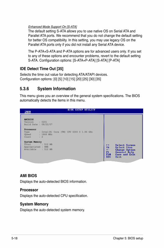
5-18 Chapter 5: BIOS setup
5.3.6 System InformationThis menu gives you an overview of the general system specifications. The BIOS automatically detects the items in this menu.
AMI BIOSDisplays the auto-detected BIOS information.
ProcessorDisplays the auto-detected CPU specification.
System MemoryDisplays the auto-detected system memory.
AMIBIOSVersion : 0201Build Date : 08/22/07
ProcessorType : Intel(R) Core (TM) CPU 6300 @ 1.86 GHzSpeed : 1866 MHzCount : 2 System MemoryTotal : 512 MB Appropriated : 8MB Available : 512 MB
Enhanced Mode Support On [S-ATA]The default setting S-ATA allows you to use native OS on Serial ATA and Parallel ATA ports. We recommend that you do not change the default setting for better OS compatibility. In this setting, you may use legacy OS on the Parallel ATA ports only if you did not install any Serial ATA device.
The P-ATA+S-ATA and P-ATA options are for advanced users only. If you set to any of these options and encounter problems, revert to the default setting S-ATA. Configuration options: [S-ATA+P-ATA] [S-ATA] [P-ATA]
IDE Detect Time Out [35]Selects the time out value for detecting ATA/ATAPI devices. Configuration options: [0] [5] [10] [15] [20] [25] [30] [35]

5-19ASUS P1/P2-P5945GCX
5.4 Advanced menuThe Advanced menu items allow you to change the settings for the CPU and other system devices.
Take caution when changing the settings of the Advanced menu items. Incorrect field values can cause the system to malfunction.
Adjust system frequency/voltage
JumperFree Configuration USB Configuration
CPU Configuration Chipset Onboard Devices Configuration PCIPnP
Exit
BIOS SETUP UTILITY Advanced
5.4.1 JumperFree Configuration
Spread Spectrum [Disabled]Allows you to enable or disable the clock generator spread spectrum. Configuration options: [Disabled] [Enabled].
Spread Spectrum [Disabled]AI Overclocking [Standard]PCI Express Frequency [Auto]
CPU (PLL1) Spread Spectrum Selection
AI Overclocking [Standard]Allows selection of CPU overclocking options to achieve desired CPU internal frequency. Select either one of the preset overclocking configuration options:
Manual - allows you to individually set overclocking parameters. Standard - loads overclocking profiles with optimal parameters for stability when
overclocking.
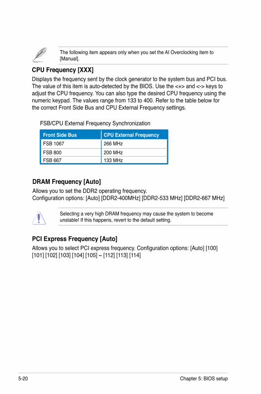
5-20 Chapter 5: BIOS setup
FSB/CPU External Frequency Synchronization
Front Side Bus CPU External FrequencyFSB 1067 266 MHzFSB 800 200 MHzFSB 667 133 MHz
DRAM Frequency [Auto]Allows you to set the DDR2 operating frequency. Configuration options: [Auto] [DDR2-400MHz] [DDR2-533 MHz] [DDR2-667 MHz]
The following item appears only when you set the AI Overclocking item to [Manual].
CPU Frequency [XXX]Displays the frequency sent by the clock generator to the system bus and PCI bus. The value of this item is auto-detected by the BIOS. Use the <+> and <-> keys to adjust the CPU frequency. You can also type the desired CPU frequency using the numeric keypad. The values range from 133 to 400. Refer to the table below for the correct Front Side Bus and CPU External Frequency settings.
PCI Express Frequency [Auto]Allows you to select PCI express frequency. Configuration options: [Auto] [100] [101] [102] [103] [104] [105] ~ [112] [113] [114]
Selecting a very high DRAM frequency may cause the system to become unstable! If this happens, revert to the default setting.
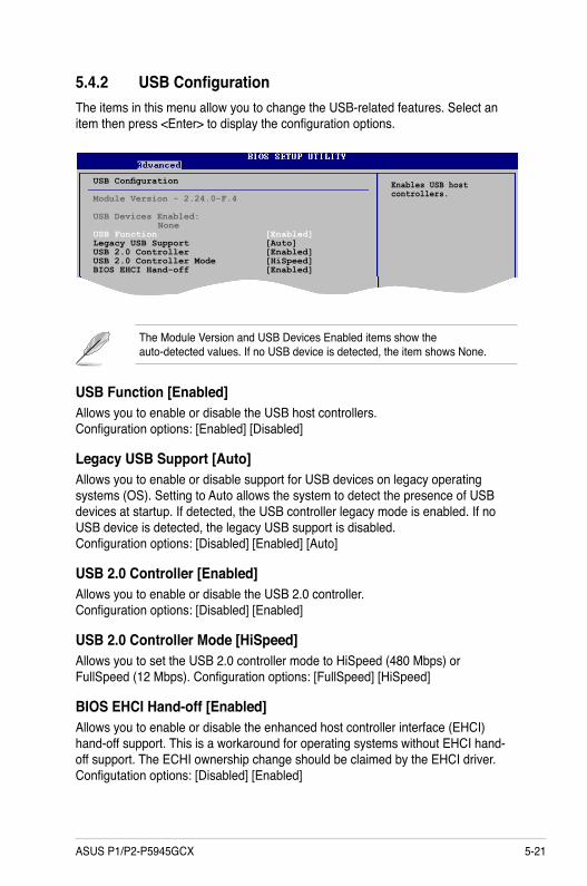
5-21ASUS P1/P2-P5945GCX
The Module Version and USB Devices Enabled items show the auto-detected values. If no USB device is detected, the item shows None.
5.4.2 USB ConfigurationThe items in this menu allow you to change the USB-related features. Select an item then press <Enter> to display the configuration options.
USB Configuration
Module Version - 2.24.0-F.4
USB Devices Enabled: NoneUSB Function [Enabled]Legacy USB Support [Auto]USB 2.0 Controller [Enabled]USB 2.0 Controller Mode [HiSpeed]BIOS EHCI Hand-off [Enabled]
USB Function [Enabled]Allows you to enable or disable the USB host controllers. Configuration options: [Enabled] [Disabled]
Legacy USB Support [Auto]Allows you to enable or disable support for USB devices on legacy operating systems (OS). Setting to Auto allows the system to detect the presence of USB devices at startup. If detected, the USB controller legacy mode is enabled. If no USB device is detected, the legacy USB support is disabled. Configuration options: [Disabled] [Enabled] [Auto]
USB 2.0 Controller [Enabled]Allows you to enable or disable the USB 2.0 controller. Configuration options: [Disabled] [Enabled]
USB 2.0 Controller Mode [HiSpeed]Allows you to set the USB 2.0 controller mode to HiSpeed (480 Mbps) or FullSpeed (12 Mbps). Configuration options: [FullSpeed] [HiSpeed]
BIOS EHCI Hand-off [Enabled]Allows you to enable or disable the enhanced host controller interface (EHCI) hand-off support. This is a workaround for operating systems without EHCI hand-off support. The ECHI ownership change should be claimed by the EHCI driver. Configutation options: [Disabled] [Enabled]
Enables USB host controllers.
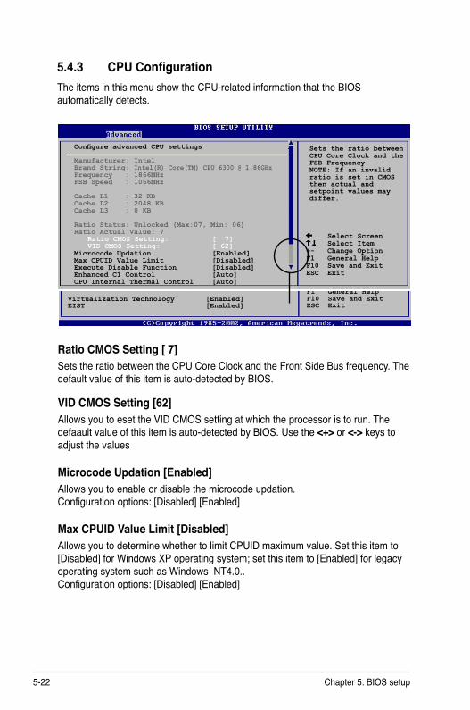
5-22 Chapter 5: BIOS setup
5.4.3 CPU ConfigurationThe items in this menu show the CPU-related information that the BIOS automatically detects.
Ratio CMOS Setting [ 7]Sets the ratio between the CPU Core Clock and the Front Side Bus frequency. The default value of this item is auto-detected by BIOS.
VID CMOS Setting [62]Allows you to eset the VID CMOS setting at which the processor is to run. The defaault value of this item is auto-detected by BIOS. Use the <+> or <-> keys to adjust the values
Microcode Updation [Enabled]Allows you to enable or disable the microcode updation. Configuration options: [Disabled] [Enabled]
Max CPUID Value Limit [Disabled]Allows you to determine whether to limit CPUID maximum value. Set this item to [Disabled] for Windows XP operating system; set this item to [Enabled] for legacy operating system such as Windows NT4.0.. Configuration options: [Disabled] [Enabled]
Select Screen Select Item+- Change OptionF1 General HelpF10 Save and ExitESC Exit
Sets the ratio between CPU Core Clock and the FSB Frequency.NOTE: If an invalidratio is set in CMOSthen actual andsetpoint values maydiffer.
Select Screen Select Item+- Change OptionF1 General HelpF10 Save and ExitESC Exit
Virtualization Technology [Enabled]EIST [Enabled]
Configure advanced CPU settings Manufacturer: IntelBrand String: Intel(R) Core(TM) CPU 6300 @ 1.86GHzFrequency : 1866MHzFSB Speed : 1066MHz Cache L1 : 32 KB Cache L2 : 2048 KB Cache L3 : 0 KB Ratio Status: Unlocked (Max:07, Min: 06)Ratio Actual Value: 7 Ratio CMOS Setting: [ 7] VID CMOS Setting: [ 62]Microcode Updation [Enabled]Max CPUID Value Limit [Disabled]Execute Disable Function [Disabled]Enhanced C1 Control [Auto]CPU Internal Thermal Control [Auto]
5-23ASUS P1/P2-P5945GCX
Execute Disable Function [Disabled]Enables or disables Intel® Execute Disable Bit function. This function enhances protection of your computer, reducing exposure to viruses and malicious buffer overflow attacks when working with its supporting software and system. Configuration options: [Disabled] [Enabled]
Enhanced C1 Control [Auto]When set to [Auto], the BIOS will automatically check the CPU’s capability to enable the C1E support. In C1E mode, the CPU power consumption is lower when idle. Configuration options: [Auto] [Disabled]
CPU Internal Thermal Control [Auto]When set to [Auto], the BIOS will automatically check the CPU’s capability to enable the C1E support. In C1E mode, the CPU power consumption is lower when idle. Configuration options: [Auto] [Disabled]
Virtualization Technology [Enabled] Allows you to enable or disable the Virtualization Technology. Virtualization enhanced by Intel® Virtualization Technology allows a platform to run multiple operating systems and applications in independent partitions. With virtualization, one computer system can function as multiple virtual systems. Configuration options: [Disabled] [Enabled]
EIST [Enabled]Allows you to enable or diable the Enhanced Intel SpeedStep Technology (EIST). Configuration options: [Enabled] [Disabled]

5-24 Chapter 5: BIOS setup
Graphic Adapter Priority [PCI/Int-VGA]Allows selection of the graphics controller to use as primary boot device. Configuration options: [Internal VGA] [PCI/Int-VGA]
Internal Graphics Mode Select [Enabled, 8MB]Sets the internal graphics mode. Configuration options: [Disabled] [Enabled, 1MB] [Enabled, 8MB]
Graphics memory type [Auto]Sets the graphics memory type. Configuration options: [Auto] [DVMT] [FIX] [DVMT+FIX]
DRAM Frequency [Auto]Allows you to set the DDR2 operating frequency. Configuration options: [Auto] [DDR2-400MHz] [DDR2-533 MHz] [DDR2-667 MHz]
Selecting a very high DRAM frequency may cause the system to become unstable! If this happens, revert to the default setting.
5.4.4 ChipsetThe Chipset menu allows you to change the advanced chipset settings. Select an item then press <Enter> to display the sub-menu.
Advanced Chipset Settings
Configure DRAM Timing by SPD [Enabled]DRAM Frequency [Auto]
Graphic Adapter Priority [PCI/Int-VGA]Internal Graphics Mode Select [Enabled, 8MB]
Graphic Memory Type [Auto]
Configure DRAM Timing by SPD [Enabled]Allows you to enable or disable configure DRAM timing by SPD. Configuration options: [Disabled] [Enabled]
Enable or disable Configure DRAM Timing by SPD
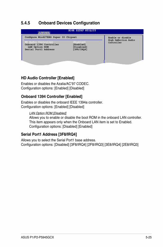
5-25ASUS P1/P2-P5945GCX
5.4.5 Onboard Devices Configuration
Configure Win627EHG Super IO Chipset
HD Audio Controller [Enabled]Onboard 1394 Controller [Enabled] LAN Option ROM [Disabled]Serial Port1 Address [3F8/IRQ4]
HD Audio Controller [Enabled]Enables or disables the Azalia/AC’97 CODEC. Configuration options: [Enabled] [Disabled]
Onboard 1394 Controller [Enabled]Enables or disables the onboard IEEE 1394a controller. Configuration options: [Enabled] [Disabled]
LAN Option ROM [Disabled]Allows you to enable or disable the boot ROM in the onboard LAN controller. This item appears only when the Onboard LAN item is set to Enabled. Configuration options: [Disabled] [Enabled]
Enable or disable High Definition Audio Controller
Serial Port1 Address [3F8/IRQ4]Allows you to select the Serial Port1 base address. Configuration options: [Disabled] [3F8/IRQ4] [2F8/IRQ3] [3E8/IRQ4] [2E8/IRQ3]
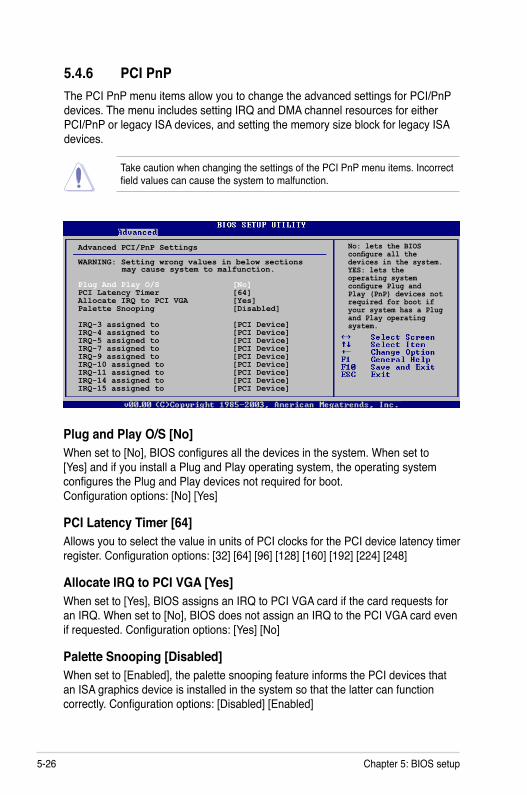
5-26 Chapter 5: BIOS setup
5.4.6 PCI PnPThe PCI PnP menu items allow you to change the advanced settings for PCI/PnP devices. The menu includes setting IRQ and DMA channel resources for either PCI/PnP or legacy ISA devices, and setting the memory size block for legacy ISA devices.
Take caution when changing the settings of the PCI PnP menu items. Incorrect field values can cause the system to malfunction.
Plug and Play O/S [No]When set to [No], BIOS configures all the devices in the system. When set to [Yes] and if you install a Plug and Play operating system, the operating system configures the Plug and Play devices not required for boot. Configuration options: [No] [Yes]
PCI Latency Timer [64]Allows you to select the value in units of PCI clocks for the PCI device latency timer register. Configuration options: [32] [64] [96] [128] [160] [192] [224] [248]
Allocate IRQ to PCI VGA [Yes]When set to [Yes], BIOS assigns an IRQ to PCI VGA card if the card requests for an IRQ. When set to [No], BIOS does not assign an IRQ to the PCI VGA card even if requested. Configuration options: [Yes] [No]
Palette Snooping [Disabled]When set to [Enabled], the palette snooping feature informs the PCI devices that an ISA graphics device is installed in the system so that the latter can function correctly. Configuration options: [Disabled] [Enabled]
No: lets the BIOS configure all the devices in the system. YES: lets the operating system configure Plug and Play (PnP) devices not required for boot if your system has a Plug and Play operating system.
Advanced PCI/PnP Settings
WARNING: Setting wrong values in below sections may cause system to malfunction.
Plug And Play O/S [No]PCI Latency Timer [64]Allocate IRQ to PCI VGA [Yes]Palette Snooping [Disabled]
IRQ-3 assigned to [PCI Device]IRQ-4 assigned to [PCI Device]IRQ-5 assigned to [PCI Device]IRQ-7 assigned to [PCI Device]IRQ-9 assigned to [PCI Device]IRQ-10 assigned to [PCI Device]IRQ-11 assigned to [PCI Device]IRQ-14 assigned to [PCI Device]IRQ-15 assigned to [PCI Device]

5-27ASUS P1/P2-P5945GCX
5.5 Power menuThe Power menu items allow you to change the settings for the ACPI and Advanced Power Management (APM). Select an item then press <Enter> to display the configuration options.
5.5.1 Suspend Mode [Auto]Allows you to select the Advanced Configuration and Power Interface (ACPI) state to be used for system suspend. Configuration options:
[S1 (POS) Only] - Enables the system to enter the ACPI S1 (Power on Suspend) sleep state. In S1 sleep state, the system appears suspended and stays in a low power mode. The system can be resumed at any time. [S3 Only] - Enables the system to enter the ACPI S3 (Suspend to RAM) sleep state. In S3 sleep state, the system appears to be off and consumes less power than in the S1 state. When signaled by a wake-up device or event, the system resumes to its working state exactly where it was left off. [Auto] - Detected by OS.
5.5.2 ACPI 2.0 Support [Disabled]Allows you to add more tables for Advanced Configuration and Power Interface (ACPI) 2.0 specifications. Configuration options: [Disabled] [Enabled]
Suspend Mode [Auto]ACPI 2.0 Support [No]ACPI APIC Support [Enabled]
APM Configuration Hardware Monitor
IRQ-XX assigned to [PCI Device]When set to [PCI Device], the specific IRQ is free for use of PCI/PnP devices. When set to [Reserved], the IRQ is reserved for legacy ISA devices. Configuration options: [PCI Device] [Reserved]
Exit
Select the ACPI state used for System Suspend.
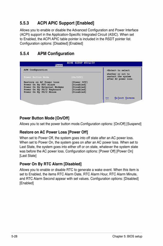
5-28 Chapter 5: BIOS setup
5.5.4 APM Configuration
APM Configuration
Power Button Mode [On/Off] Restore on AC Power Loss [Power Off]Power On By RTC Alarm [Disabled] Power On By External Modems [Disabled]Power On By PS/2 Keyboard [Disabled]Power On By PS/2 Mouse [Disabled]
<Enter> to selectwhether or not to restart the system after AC power loss.
5.5.3 ACPI APIC Support [Enabled]Allows you to enable or disable the Advanced Configuration and Power Interface (ACPI) support in the Application-Specific Integrated Circuit (ASIC). When set to Enabled, the ACPI APIC table pointer is included in the RSDT pointer list. Configuration options: [Disabled] [Enabled]
Power Button Mode [On/Off]Allows you to set the power button mode.Configuration options: [On/Off] [Suspend]
Restore on AC Power Loss [Power Off]When set to Power Off, the system goes into off state after an AC power loss. When set to Power On, the system goes on after an AC power loss. When set to Last State, the system goes into either off or on state, whatever the system state was before the AC power loss. Configuration options: [Power Off] [Power On] [Last State]
Power On By RTC Alarm [Disabled]Allows you to enable or disable RTC to generate a wake event. When this item is set to Enabled, the items RTC Alarm Date, RTC Alarm Hour, RTC Alarm Minute, and RTC Alarm Second appear with set values. Configuration options: [Disabled] [Enabled]

5-29ASUS P1/P2-P5945GCX
The computer cannot receive or transmit data until the computer and applications are fully running. Thus, connection cannot be made on the first try. Turning an external modem off and then back on while the computer is off causes an initialization string that turns the system on.
Power On By PS/2 Keyboard [Disabled]Allows you to use specific keys on the keyboard to turn on the system. This feature requires an ATX power supply that provides at least 1A on the +5VSB lead. Configuration options: [Disabled] [Space Bar] [Ctrl-Esc] [Power Key]
Power On By PS/2 Mouse [Disabled]When set to [Enabled], this parameter allows you to use the PS/2 mouse to turn on the system. This feature requires an ATX power supply that provides at least 1A on the +5VSB lead. Configuration options: [Disabled] [Enabled]
Power On By External Modems [Disabled]This allows either settings of [Enabled] or [Disabled] for powering up the computer when the external modem receives a call while the computer is in Soft-off mode. Configuration options: [Disabled] [Enabled]
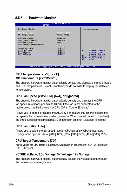
5-30 Chapter 5: BIOS setup
CPU Temperature [xxxºC/xxxºF] MB Temperature [xxxºC/xxxºF]The onboard hardware monitor automatically detects and displays the motherboard and CPU temperatures. Select Disabled if you do not wish to display the detected temperatures.
CPU Fan Speed [xxxxRPM], [N/A], or [Ignored]The onboard hardware monitor automatically detects and displays the CPU fan speed in rotations per minute (RPM). If the fan is not connected to the motherboard, the field shows N/A.CPU Q-Fan Control [Enabled]
Allows you to enable or disable the ASUS Q-Fan feature that smartly adjusts the fan speeds for more efficient system operation. When this field is set to [Enabled], the three succeeding items appear. Configuration options: [Disabled] [Enabled]
CPU Fan Ratio [Auto]Allows you to select the fan speed ratio for CPU fan at low CPU temperature. Configuration options: [Auto] [90%] [80%] [70%] [60%] [50%] [40%] [30%] [20%]
CPU Target Temperature [70o]Allows you to set CPU target temperature. Configuration options: [60o] [62o] [64o] [66o] [68o] [70o] ~ [86o] [90o]
VCORE Voltage, 3.3V Voltage, 5V Voltage, 12V VoltageThe onboard hardware monitor automatically detects the voltage output through the onboard voltage regulators.
5.5.5 Hardware Monitor
Hardware Monitor
CPU Temperature [73.5ºC/164ºF]MB Temperature [39ºC/102ºF]
CPU Fan Speed [2896RPM] CPU Q-Fan Control [Enabled]CPU Fan Ratio [Auto]CPU Target Temperature [70o]
VCORE Voltage [ 1.272V]3.3V Voltage [ 3.296V]5V Voltage [ 5.196V]12V Voltage [12.091V]
CPU Temperature
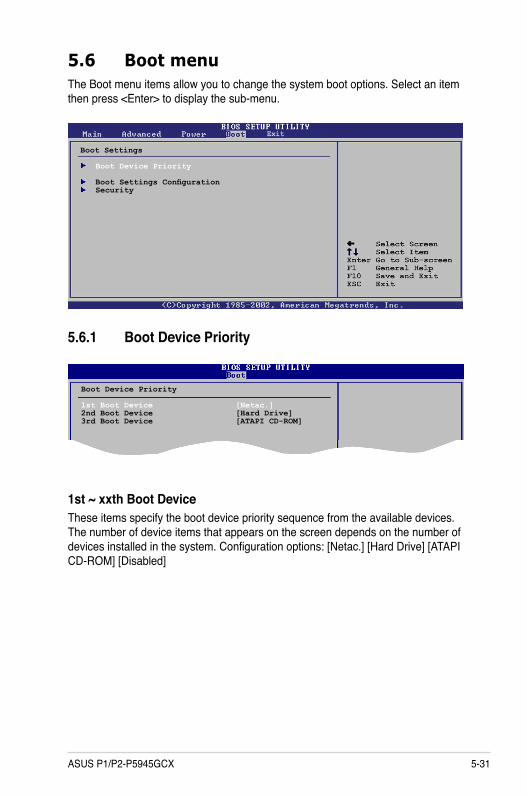
5-31ASUS P1/P2-P5945GCX
5.6 Boot menuThe Boot menu items allow you to change the system boot options. Select an item then press <Enter> to display the sub-menu.
Boot Settings
Boot Device Priority
Boot Settings Configuration Security
5.6.1 Boot Device Priority
1st ~ xxth Boot Device These items specify the boot device priority sequence from the available devices. The number of device items that appears on the screen depends on the number of devices installed in the system. Configuration options: [Netac.] [Hard Drive] [ATAPI CD-ROM] [Disabled]
Boot Device Priority
1st Boot Device [Netac.]2nd Boot Device [Hard Drive]3rd Boot Device [ATAPI CD-ROM]
Exit

5-32 Chapter 5: BIOS setup
5.6.2 Boot Settings Configuration
Boot Settings Configuration
Quick Boot [Enabled]Full Screen Logo [Enabled]Bootup Num-Lock [On]Hit ‘DEL’ Message Display [Enabled]Interrupt 19 Capture [Disabled]
Allows BIOS to skip certain tests while booting. This will decrease the time needed to boot the system.
Set this item to [Enabled] to use the ASUS MyLogo2™ feature.
Quick Boot [Enabled]Enabling this item allows the BIOS to skip some power on self tests (POST) while booting to decrease the time needed to boot the system. When set to [Disabled], BIOS performs all the POST items. Configuration options: [Disabled] [Enabled]
Full Screen Logo [Enabled]This allows you to enable or disable the full screen logo display feature. Configuration options: [Disabled] [Enabled]
Bootup Num-Lock [On]Allows you to select the power-on state for the NumLock. Configuration options: [Off] [On]
Hit ‘DEL’ Message Display [Enabled]When set to Enabled, the system displays the message “Press DEL to run Setup” during POST. Configuration options: [Disabled] [Enabled]
Interrupt 19 Capture [Disabled]When set to [Enabled], this function allows the option ROMs to trap Interrupt 19. Configuration options: [Disabled] [Enabled]

5-33ASUS P1/P2-P5945GCX
5.6.3 SecurityThe Security menu items allow you to change the system security settings. Select an item then press <Enter> to display the configuration options.
Security Settings
Supervisor Password : Not InstalledUser Password : Not Installed
Change Supervisor Password
<Enter> to changepassword.<Enter> again to disabled password.
Change Supervisor PasswordSelect this item to set or change the supervisor password. The Supervisor Password item on top of the screen shows the default Not Installed. After you set a password, this item shows Installed.
To set a Supervisor Password:
1. Select the Change Supervisor Password item and press <Enter>.2. From the password box, type a password composed of at least six letters
and/or numbers, then press <Enter>. 3. Confirm the password when prompted.
The message “Password Installed” appears after you successfully set your password.
To change the supervisor password, follow the same steps as in setting a user password.
To clear the supervisor password, select the Change Supervisor Password then press <Enter>. The message “Password Uninstalled” appears.
If you forget your BIOS password, you can clear it by erasing the CMOS Real Time Clock (RTC) RAM. See section “4.3 Jumpers” for information on how to erase the RTC RAM.

5-34 Chapter 5: BIOS setup
After you have set a supervisor password, the other items appear to allow you to change other security settings.
User Access Level (Full Access]This item allows you to select the access restriction to the Setup items. Configuration options: [No Access] [View Only] [Limited] [Full Access]
No Access prevents user access to the Setup utility.
View Only allows access but does not allow change to any field.
Limited allows changes only to selected fields, such as Date and Time.
Full Access allows viewing and changing all the fields in the Setup utility.
Change User PasswordSelect this item to set or change the user password. The User Password item on top of the screen shows the default Not Installed. After you set a password, this item shows Installed.
To set a User Password:
1. Select the Change User Password item and press <Enter>.2. On the password box that appears, type a password composed of at least six
letters and/or numbers, then press <Enter>. 3. Confirm the password when prompted.
The message “Password Installed” appears after you set your password successfully.
To change the user password, follow the same steps as in setting a user password.
Clear User PasswordSelect this item to clear the user password.
Security Settings
Supervisor Password : InstalledUser Password : Not Installed
Change Supervisor PasswordUser Access Level [Full Access]Change User PasswordPassword Check [Setup]
<Enter> to change password.<Enter> again to disabled password.
Exit
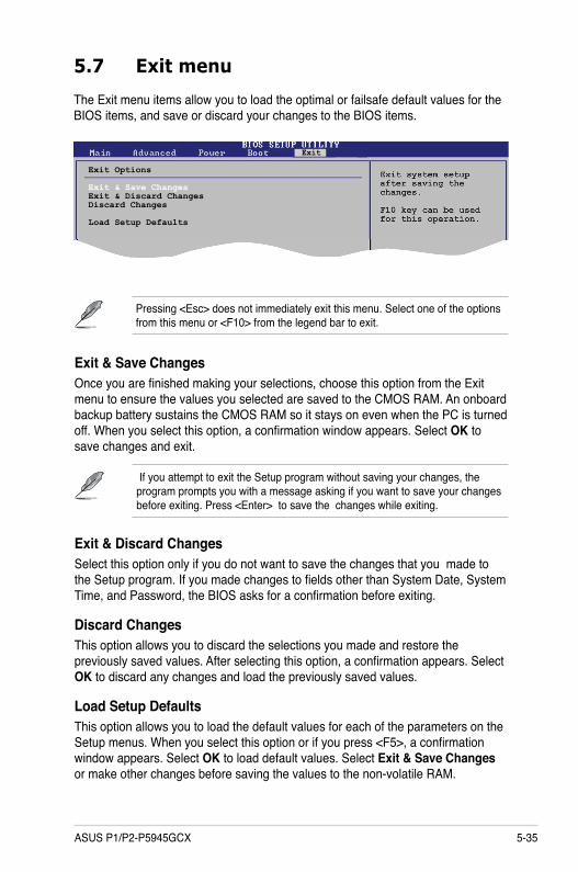
5-35ASUS P1/P2-P5945GCX
5.7 Exit menu
Pressing <Esc> does not immediately exit this menu. Select one of the options from this menu or <F10> from the legend bar to exit.
The Exit menu items allow you to load the optimal or failsafe default values for the BIOS items, and save or discard your changes to the BIOS items.
Exit Options
Exit & Save ChangesExit & Discard ChangesDiscard Changes
Load Setup Defaults
Exit & Discard ChangesSelect this option only if you do not want to save the changes that you made to the Setup program. If you made changes to fields other than System Date, System Time, and Password, the BIOS asks for a confirmation before exiting.
Discard ChangesThis option allows you to discard the selections you made and restore the previously saved values. After selecting this option, a confirmation appears. Select OK to discard any changes and load the previously saved values.
Load Setup Defaults This option allows you to load the default values for each of the parameters on the Setup menus. When you select this option or if you press <F5>, a confirmation window appears. Select OK to load default values. Select Exit & Save Changes or make other changes before saving the values to the non-volatile RAM.
If you attempt to exit the Setup program without saving your changes, the program prompts you with a message asking if you want to save your changes before exiting. Press <Enter> to save the changes while exiting.
Exit & Save ChangesOnce you are finished making your selections, choose this option from the Exit menu to ensure the values you selected are saved to the CMOS RAM. An onboard backup battery sustains the CMOS RAM so it stays on even when the PC is turned off. When you select this option, a confirmation window appears. Select OK to save changes and exit.
Exit

5-36 Chapter 5: BIOS setup