p09503 electrophotographic development and transfer station
DESCRIPTION
P09503 Electrophotographic Development and Transfer Station. Team Members. Project Background. Project Family Printing and Imaging Systems Technologies Track Customer Print Research and Imaging Science Modeling Laboratory (PRISM ) - PowerPoint PPT PresentationTRANSCRIPT

P09503Electrophotographic Development and Transfer Station

Team MembersName Discipline Role
David Schwartz ISE Team Lead – Warning Signs
Ruth Gay ME Paper Delivery System
Phillip Lopez ME Ozone Filter
Dan Summers ME ME Support
Rachel Chrash EE LED Exposure System
Min-Shi Hsiao EE PC Potential Measurement
Andrew Kearns EE Transfer Drum Speed Measurement, Camera System
Sasha Oliver CE User Interface

Project Background• Project Family▫Printing and Imaging Systems Technologies Track
• Customer▫Print Research and Imaging Science Modeling Laboratory (PRISM)
The Print Research and Imaging Systems Modeling lab will serve as a conduit between industry and academia, working to evaluate and anticipate the print systems research needs of printer and printing product companies, and directing relevant projects to researchers and students in the areas of Printers & Displays, Color Science, Vision Science, Systems Engineering, and Printing.
Contact: Dr. Marcos Esterman – Associate Professor, Industrial and Systems Engineering

Project Description• Working Electrophotographic
station to vary both the printing material and the printing process parameters as to better understand and improve the performance of similar printing systems.
• End Users PRISM Lab Center for Imaging Science
Deliverables1. An inventory and status of current
sub-systems, including needed support systems.
2. A working Electrophotographic Station.
3. Demonstrably improved device safety.
4. An improved user interface (includes control and display functions)
5. Device documented for use, maintenance and upgrade of the device (User & Lab Technician Manual)
6. Demonstrably Improved Sensing and Control Subsystem

What is Electrophotography?• Electrophotography is base
technology that is used in many modern day copiers and printers
• Six Step Process to transfer an electrostatic image to a final printed page▫ Charging▫ Exposure▫ Development▫ Transfer▫ Fusing ▫ Cleaning
• P09503 only includes the first four
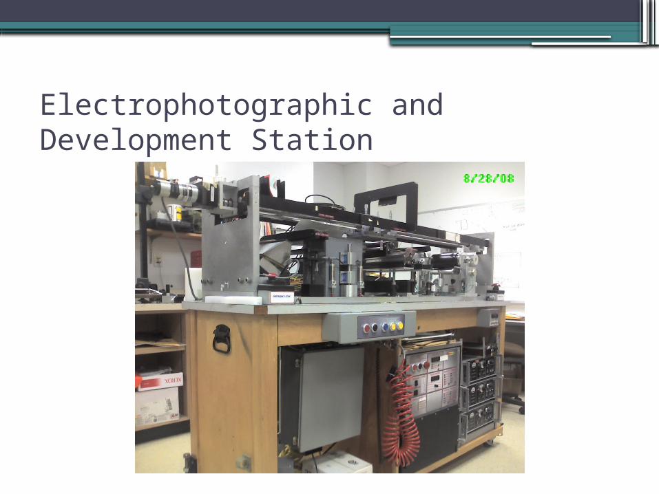
Electrophotographic and Development Station

Electrophotographic and Development Station
ChargingExposure
Development Transfer

ConsultantsRIT Faculty Professional
• Jonathon Arney, Ph.D▫ Center for Imaging Science
Physical & Optical Measurements• Susan Farnand, Ph.D
▫ Center for Imaging Science Color and Vision Science
• John D. Wellin▫ Mechanical Engineering
Control Systems• Marcos Esterman, Ph.D
▫ Industrial and Systems Engineering Product & Process Development
• Bill Nowak – Xerox▫ Principle Engineer
Motion and Quality Systems• Gregory Miller – Kodak▫ Software Engineer

Customer Needs & Functional Diagram1. Is Operational2. Is Safe3. Minimize user
Intervention4. Can Monitor Key
Process Parameters5. Can operate and
monitor machine from one interface
6. Easy to learn to use

Ozone Fan/Filter Assembly•Reduce and Secure Ozone
Test Stand▫Ozone hazardous to
humans if exposed to enough
▫ Law states maximum ozone in A/C Space is 0.05 ppm
▫>0.200 ppm increases risk of health issues
•Two Options▫Verify current system or ▫ Implementation of further
improvement to control Ozone Levels

Monitoring Potential on Photoconductor
•Monitoring potential of photosensitive material will help characterize exposure input noise source
•Charge v. Exposure plot after measurement can be viewed
•Dark Decay Research Possible

LED Exposure System• LED Print Heads used in
copiers and printers to expose Photosensitive Material are commonly used
• LED Exposure system to replace current incandescent system
• Advantages▫ More versatile and reliable light
source▫ Low Power Consumption▫ Longer Bulb Life▫ No potential for overheat▫ Inexpensive to replace
incandescentlight source
collimatinglens
image planewith modulating masks
image planewith modulating masks
4x4 array of LEDs
Current System Better LED system
incandescentlight source
collimatinglens
image planewith modulating masks
image planewith modulating masks
4x4 array of LEDs
Current System Better LED system

Paper Delivery System•Existing roller system
requires manually catching paper after application of toner from roller
•Possible risks of manual handling▫Shock Short from High
Voltage Roller▫Pinch Point of Rollers and
Pneumatics▫Marred Image Quality

High Visibility Warning Signs• Purpose of warning signs
▫ Alert user to specific hazard▫ Identify how hazard can be
avoided• Current signs do not accomplish
this• Remove current warning signs• Replace with ISO designed signs• Add new ISO signs where needed

Camera System•Purpose is to gain
understanding of how image is developed onto photoreceptive material
•Photoreceptive material imaged after development and before transfer

Transfer Roller Speed Measurement• Speed of transfer roller critical to
timing control and image quality• Need to assure that transfer
drum rotates at the same speed as the moving photoconductor as to not elongate/condense the image
• Need to assure that the transfer roller will be in the proper position for transfer to paper

Labview Control Interface• Current control system is done
via PLC• Better solution needed to replace
current system with a new user friendly interface▫ Automatic and Manual Setting
• Labview uses dataflow programming to define inputs/outputs and execution sequence of the virtual instrument
• Connect devices directly to DAQ to allow for more robust control

Technical Risk Assessment•Data Acquisition Implementation – Coding
Complications / Integration with Subsystems▫Mitigation: Primary Focus During SD II
•Obtaining Optimal Parameters (>10) for EP Process▫Mitigation: Experimental Design to optimize
parameters, Consult with Xerox and CIS•Toner and Developer Contamination▫Mitigation: Implement Air Filtration System and
Warning Signs

Current State of Design•Current design meets all feasible customer needs▫Customer understands unfeasible needs
•Current design meets all engineering specifications•Budget = $1500▫Total Expenditures < $900
•Schedule▫On Schedule, no Design Delays

Product Development Process Phase•Phase 0: Planning▫Completed
•Phase 1: Concept Development▫Completed
•Phase 2: System Level Design▫Completed
•Phase 3: Detailed Design▫Completed
•Phase 4: Testing and Refinement▫Will begin in SD II

Senior Design II Schedule and MilestonesMilestone Duration Completion Date
User Manual Complete 14 Days 12/18/08
Ozone Decision 39 Days 1/9/09
PC Potential Measurement Device Complete
35 Days 2/10/09
LED Complete 29 Days 2/2/09
Paper Delivery System Complete
43 Days 2/20/09
Warning Signs Complete 18 Days 1/7/09
Labview/Camera/Speed Complete
73 Days 3/25/08

Questions