p r o d u c t io n l it e r a t u r e kits common to
TRANSCRIPT

Page 1
GUIDE TO THE M1-4 AND M1-5 INTEGRATED MODULARCONTROL USED IN L SERIES 3 THROUGH 30 TON UNITS
Litho U.S.A. 503,872M8/98Supersedes 4/98
E1998M1-4 AND M1-5 INTEGRATED
MODULAR CONTROL (IMC)
KITS COMMON TO HEATINGAND COOLING EQUIPMENT
PRODUCTION LITERATURE
TABLE OF CONTENTS
IMC BOARD BY UNIT 2. . . . . . . . . . . . . . . . . . . . . . . . . . . . .
UNIT MODEL NUMBER 2. . . . . . . . . . . . . . . . . . . . . . . . . . .
IMC AND ADD--ON BOARDS 3. . . . . . . . . . . . . . . . . . . . . .
IMC BOARD LOCATION 3. . . . . . . . . . . . . . . . . . . . . . . . . . .
IMC BOARD COMPONENTS 4. . . . . . . . . . . . . . . . . . . . . . .
UNIT START--UP 7. . . . . . . . . . . . . . . . . . . . . . . . . . . . . . . . . .
DIAGNOSTICS 8. . . . . . . . . . . . . . . . . . . . . . . . . . . . . . . . . . .
MAIN CONTROL OPERATION 12. . . . . . . . . . . . . . . . . . . . .
LOW AMBIENT FAN CYCLING 16. . . . . . . . . . . . . . . . . . . . .
OPTIONAL ECONOMIZER 18. . . . . . . . . . . . . . . . . . . . . . . . .
IAQ OPERATION 24. . . . . . . . . . . . . . . . . . . . . . . . . . . . . . . . .
TESTING UNIT FUNCTION 26. . . . . . . . . . . . . . . . . . . . . . . .
DISPLAYING SENSOR READINGS 28. . . . . . . . . . . . . . . . .
ECTO CONTROL PARAMETERS 30. . . . . . . . . . . . . . . . . . . .
IMC BOARD INPUTS AND OUTPUTS 39. . . . . . . . . . . . . . .
GENERAL
The integrated modular control system (IMC) is aseries of control boards designed to indicate unitoperation, increase reliability, and maketroubleshooting easier. The IMC providesprogrammable control parameters (such asvarying compressor on/off intervals) and has thecapability to communicate with personalcomputers. As in standard installations, athermostat is required for system operation.
The main control, or A55 (M1) board, is thecommon control board used in all “L” seriesunits. Add--on boards are connected to the mainboard to “build” control variations dependingon type and capacity of unit. An A56 (EM1)economizer add--on board connects to the M1board when an optional economizer is installedin the unit.
See table 1 to determine which IMC controlboards are provided in each unit. Figure 1identifies unit model number. Figure 2 shows thelocation of add--on boards in relation to the maincontrol board. Figure 3 shows the IMC boardlocation in each unit.
D Indicates thermostat demand
D Makes troubleshooting easier
D Increases unit and component reliability
D Provides consistent central control location
D Provides adjustable control parameters
D Interfaces with personal computers
INTEGRATED MODULAR CONTROL (IMC)FEATURES

Page 2
LGA/LCA036, 042, 048, 060, 072 M1 OPT(3, 3-1/2, 4, 5, & 6 TON)
LHA088 M1 OPT(7.5 TON)
LGA/LCA088 & 100 M1 C1 OPT(7.5 & 8.5 TON)
LGA/LCA102, 120, & 150 M1 C1 OPT(8.5, 10, & 12.5 TON)
LHA090 & 120 M1 HP1 OPT(7.5 & 10 TON)
LGA156, 180, 210, 240, 300S M1 C1 C2 G1 OPT(15, 18.5, 20, & 25 TON)
LCA156, 180, 210, 240, & 300S M1 C1 C2 OPT OPT(15, 18.5, 20, & 25 TON)
LHA180 & 240 M1 OPT HP1 OPT(15 & 20 TON)
LGA300H & 360 M1 C1 C2 G1 OPT(25 & 30 TON)
LCA300H & 360 M1 C1 C2 OPT OPT(25 & 30 TON)
M1 C1 C2 E1 G1 HP1 EM1
TABLE 1IMC BOARDS BY UNIT
B
C
D
BOXSIZE
A55 A56A57 A58A59 A60 A61UNIT
A+
A
Minor Revision Number
L GA Y
Unit TypeL = Commercial Package Unit
Unit TypeG = Cooling w/ Gas HeatC = Cooling Only (w/ opt. Electric Heat)H = Heat Pump
Major Design SequenceA = First Generation
1180
Cooling Capacity Tons
S
Cooling EfficiencyS = Standard EfficiencyH = High Efficiency
Heat TypeNOTE —This space is intentionally left blank,
it will be filled in on unit nameplatedepending on type of heat ordered.
VoltageY = 208/230v-3 phase-60hzG = 460v-3 phase-60hzJ = 575v-3 phase-60hzM=380/420v-3 phase -50 hz
120=10 ton150=12-1/2 ton156=13 ton180 = 15 ton210 = 17.5 ton240= 20 ton300=25 ton360=30 ton
036=3 ton042=3-1/2 ton048=4 ton060=5 ton072=6 ton088=7--1/2 ton090=7--1/2 ton100=8--1/2 ton102=8-1/2 ton
FIGURE 1
UNIT MODEL NUMBER

Page 3
IMC AND ADD--ON BOARD LOCATION AND OPERATION
A55 (M1):
A56 (EM1):Optional
Economizerand/or PowerExhaust Fan
A57 (C1):Second com-
pressor1 Outdoor fan
A58 (G1):Second Gas Valve
A60 (E1):Second Electric
Heat Section
A59 (C2):Compressors 3 or 4
4 Outdoor Fans
or
A61 (HP1):Heat Pump
Compressor 23 Outdoor fans
1 Reversing valve
or
FIGURE 2
1 Blower1 Compressor1 Outdoor fan
1 Gas valve1 Reversing valve
1 Electric heat section
HEATSECTION
LGA, LCA, LHA7-1/2 THROUGH 12-1/2 TON
LGA, LCA, LHA13 THROUGH 30 TON
COND./OUTDOOR
COILSECTION
BLOWERSECTION
HEATSECTION
A55
COND./OUTDOOR
COILSECTION
A55
HEATSECTION
A55 (M1) MAIN CONTROL PANEL LOCATION BY UNIT
FIGURE 3
COND./OUTDOOR
COILSECTION
BLOWERSECTION
A55
LGA, LCA, LHA3 THROUGH 6 TON

Page 4
IMC BOARD COMPONENTSLED READOUT
On unit power-up the A55 M1 board LED readout willdisplay “8.8.8.”, within seconds, the “8.8.8.” readout willflash several times and turn off. Error codes are the onlyreadings that will be displayed without DIP switchchanges. See “Diagnostics” section.
RESETTING THE CONTROL
Reset the IMC control with the pushbutton located to theright of the LED readout. Hold down the pushbutton for atleast three seconds to reset the IMC control. The LEDreadout will display “8.8.8.”, flash several times, and turnoff.
HEARTBEAT LED
Each control board has a green flashing “heartbeat” LED.The heartbeat LED will flash indicating normal operation.See table 2 for an explanation of heartbeat LEDoperation.
DEFECTIVE BOARD(REPLACE)
TABLE 2HEARTBEAT LED OPERATION
A55 (M1)BOARD
ADD--ONBOARDS
HEARTBEATLED STATUS
FLASHING
*FLICKERING
STEADY OFF
STEADY ON
NA
*A “FLICKERING” LED WILL FLASH SIGNIFICANTLY FASTERTHAN THE A55 HEARTBEAT LED.
NORMALOPERATION
CHECK ELECTRICALCONNECTIONS
NO VOLTAGE TOM1 BOARD; SEE
FIGURE 4
NORMALOPERATION
DEFECTIVE BOARD(REPLACE)
NO VOLTAGE TOM1 BOARD; SEE
FIGURE 4
CHECK 24 VOLT SUPPLY TO A55(M1) MAIN CONTROL BOARD
FIGURE 4
P114
TB34
A55 (M1) BOARD
24 VOLTS READ DURINGNORMAL OPERATION
THERMOSTAT INPUT INDICATING LED’S
Thermostat input indicating LED’s are located on the M1board above P117 connector. LED’S indicate athermostat demand only. See figure 5.
THERMOSTAT INPUT INDICATING LED’S
FIGURE 5
G
W1
W2
Y1
Y2
OCP
-- Blower on
-- First stage heat
-- Second stage heat
-- First stage cool
-- Second stage cool
-- Occupied
NOTE -- LED’s are energized by 24 vac thermostat inputs only.
DIP SWITCH SETTINGS
Make sure DIP switches are set as shown in figures 6, 7,and 8. DIP switch settings are particular to each type ofunit and must be set correctly for proper unit operation.Economizer is optional. Set A56 (EM1) economizer boardDIP switches as shown in economizer section.
IMPORTANT - Check DIP switches BEFORE applyingpower unit. The IMC checks switch position onpower-up and after a reset.
UNIT DIP SWITCH SETTINGS (A55)
FIGURE 6
SW1
ON
HPGASSHIFT1PH
UNIT
LGA SINGLEPHASE UNITS
LHA SINGLEPHASE UNITS
SW1
ON
HPGASSHIFT1PH
UNIT
SW1
ON
HPGASSHIFT1PH
UNIT
LGA THREEPHASE UNITS
LHA THREEPHASE UNITS
SW1
ON
HPGASSHIFT1PH
UNIT
LCA SINGLEPHASE UNITS
SW1
ON
HPGASSHIFT1PH
UNIT
LCA THREEPHASE UNITS
SW1
ON
HPGASSHIFT1PH
UNIT
“Shift” switch will be addressed in “Testing Unit Function” section.
GAS
COOL
HEATPUMP
“OFF”POSITION
“ON”POSITION

Page 5
FLASHING GREEN “HEART-BEAT” LED INDICATESNORMAL OPERATION
A55 (M1) MAIN CONTROL BOARD
P110
UNIT MODE INDICATORS(THERMOSTAT INPUTS)
DIPSWITCHES
COMPUTERCOMMUNICATION
PORTS
EXPANSIONPORT
EXPANSIONPORT
EXPANSIONPORTS
LED READOUT
SW1SW2SW3
BUSTERM
DISPLAYPUSHBUTTON
UNITADDRESS MODE UNIT
P110
NUMBER “1” TO THE RIGHT OF THEPLUG INDICATES TERMINAL NUMBER
1 STARTS ON THE RIGHT
9 8 7 6 5 4 3 2 1
1 1 1 1
1
MAIN CONTROL BOARDSOFTWARE VERSIONPRINTED ON U12 CHIP
NOTE--CONNECTOR NOMENCLATURE ONBOARD DENOTES GAS UNIT FUNCTIONS.
COMMUNICATION BUSTERMINATION JUMPER
HPGASSHIFT1PH
UNITRECALLECTOTEMP
1248
16
TEST 1
DATATRANSMIT
LED
XMIT

Page 6
IMC BOARD COMPONENTSDIP SWITCH SETTINGS - Continued
A59 (C2) DIP SWITCH SETTINGS
FIGURE 7
FAN
COMP
6LGA/LCA156 & 180 which containfour condenser fans and threecompressors.
LGA/LCA300H which containsix condenser fans and fourcompressors.
43 4
SW1
FAN
COMP
6 43 4
SW1
FAN
COMP
6 43 4
SW1
LGA/LCA210, 240, 300S whichcontain four condenser fans and fourcompressors.
(C AND D BOX NON--HEAT PUMP UNITS ONLY)
LGA/LCA360 which contain sixcondenser fans and threecompressors.
FAN
COMP
6 43 4
SW1
A61 (HP1) DIP SWITCH SETTINGS
FIGURE 8
FAN
SW1
2LHA090 & 120 which contain two fans.
LHA180 & 240 which contain four fans.
4
FAN
SW1
2 4
(B AND C BOX HEAT PUMP UNITS ONLY;NO HEAT PUMPS IN D BOX SIZE)
Switch #2 is not used.
PUSHBUTTON
The pushbutton has various functions depending on DIPswitch settings. The pushbutton is used to toggle throughdisplay readouts and turn outputs off and on.
By-Passing Delays
With DIP switches in normal operation setting, a shortpush of the pushbutton will bypass timers (such ascompressor minimum run, blower delay, and compressorminimum-off). Delays are bypassed to energize unitfunctions immediately (or de-energize) for start-up andtroubleshooting purposes.
NOTE - Each unit contains various delays and controlcomponents. Not all units will have the samecomponents. See unit wiring schematic for applicabletimers and delays.
Example:
If the unit contains a blower delay, the delay will keep theblower from immediately starting. A short push of thepushbutton will bypass this delay and the blower willoperate.
In the same manner, if the unit has a compressorminimum run delay, a short push of the pushbutton willbypass the delay and the compressor(s) will de-energize.
DATA TRANSMIT LED
The yellow LED flashes when the IMC is transmitting datato an external device such as a PC or energymanagement system.
CHECK SOFTWARE VERSION
Use the MODE DIP switch to check the A55 (M1) softwareversion. See figure 9.
CHECK A55 MAIN BOARD SOFTWARE VERSION
FIGURE 9
SW2
ON
UNIT TESTRECALLECTOTEMP
MODESet the MODE DIP “UNITTEST” and “RECALL”switches #1 and #2 to “ON”
Readout will displaysoftware version

Page 7
UNIT START--UPVERIFY IMC BOARD FUNCTIONSOn initial unit start-up identify the following IMC boardfunctions:
IMPORTANT - Before applying power, make sure MODE DIP
switches, and UNIT “SHIFT” switch are off. At least one UNIT
ADDRESS switch should be on.
1-- Heartbeat LED on each board will flash.
2-- LED readout will flash “8.8.8” and turn off.
3-- Thermostat input indicating LED’s willappropriately turn on.
Consider the IMC an input and output junction point;thermostat inputs at P110 result in an output to unitcomponents (see 24VAC BO signal types in Input andOutput tables). If the heartbeat LED is not flashing, seetable 2 for heartbeat operation. If the LED readoutcontains a code, refer to the “Diagnostics” section totroubleshoot. If the thermostat input indicating lights arenot responding appropriately, check the thermostat.
UNIT OPERATION
Voltage may be applied to test major unit components byusing the IMC testing function, or by using jumper wireson TB1.
UNIT START-UP WITH IMC BOARD
Use “Testing Unit Function” section to simulatethermostat inputs. If outdoor fans, blowers, reversingvalves, or the service relay do not respond appropriately,delays or low ambient temperatures may be preventingoperation. In that case, use “Testing Unit Function”section to create an output from the IMC to test specificcomponents.
UNIT START-UP WITH TB1 JUMPERS
Use figure 10 to check unit operation.
Delays or low ambient temperatures may prevent outdoorfan, blower, reversing valve, or the service relayoperation. Use “Testing Unit Function” section to createan output from the IMC to test specific components.
MAINTAIN BLOWER OPERATION;LEAVE JUMPERS IN PLACE UNTILUNIT CHECK--OUT IS COMPLETE
FIGURE 10
TB1 UNIT CHECK--OUT
1 2 3 4 5 6 7 8 9 10 11 12 131415 16 17 18
TB1
G Y1Y224V 1--Disconnect power or turn thermostat (or electronictemperature control device) off.
2--Jumper terminals 6 (24V) to 3 (G) to maintain blower opera-tion throughout checkout.
3--Jumper terminals 8 & 9 to maintain occupied mode.
4--Jumper terminals as shown below to cycle unit.
JUMPERTERMINAL UNIT FUNCTION
6--18 (Y1) FIRST--STAGE COOLING
6--12 (Y2) SECOND--STAGE COOLING
6-- 2 (W1) FIRST--STAGE HEATING
6--13 (W2) SECOND--STAGE HEATING
APPROPRIATE THERMOSTAT INPUT INDICATING LED ON IMC (LOWERLEFT CORNER) WILL ENERGIZE AS EACH JUMPER IS INSTALLED
NOTE -- When a jumper is removed, a delay maykeep a component functioning. A short press onthe IMC pushbutton will reset the delay.
THERMOSTATINPUT LED’S
19
NOTE -- Applies only to units using electro--mechanical thermostats; refer to manufacturer’sinformation when using electronic thermostats or direct digital controls (DDC).

Page 8
DIAGNOSTICSIMC CONTROL ERROR CODES
When an error occurs, the A55 M1 board will display anerror code which corresponds to control function. Seetable 3 and figure 11. Error codes are stored and can berecalled later.
CONTROL ERROR CODE READOUT EXAMPLE
FIGURE 11
ERROR CODE “12” INDICATES S4 HIGHPRESSURE SWITCH IS OPEN
To read stored error codes set MODE DIP “RECALL”switch #2 to “ON”. See figure 12.
DIP SWITCH ERROR CODE RECALL SETTING
FIGURE 12
SW2
ON
UNIT TESTRECALLECTOTEMP
MODE
ERROR CODE READOUT “13” INDICATES S4HIGH PRESSURE SWITCH HAS OPENED THREETIMES (DEFAULT) AND COMPRESSOR ONE HASBEEN DE--ENERGIZED (SEE UNIT DIAGRAM; K1COMPRESSOR 1 CONTACTOR IS IN S4 LEG).
STORED ERROR CODE EXAMPLE:
The most recent error code will be displayed first. If nocodes are stored, a zero will be displayed. Stored codesare displayed in reverse order with each short push of thepushbutton. When the code no longer changes, the lastcode has been reached. To read the error codes again,turn the MODE DIP “RECALL” switch #2 off and back on.The most recent error code will again be displayed (withlater codes stored in reverse).
Example:
1-Set MODE DIP “RECALL” switch #2 to “ON”. See figure12.
2-Read display and refer to Control Error Code tables.
ERASE STORED ERROR CODES
To erase stored error codes the MODE DIP “RECALL”switch must be on. Hold down the pushbutton until a zerois displayed. A zero indicates that no error codes arestored.
RESET LOCKOUT CONDITIONS
The IMC Error Code table 3 will indicate an error condition(such as a high pressure switch tripping). If an errorresults in a lock-out condition, two successive shortpushes of the pushbutton will reset counters, lockoutconditions, and timers.
Example:
Error code 13 indicates that the first-stage high pressureswitch has opened three times (default) and the controlhas de-energized the compressor. A double push on thepushbutton will restart the compressor.
SERVICE LIGHT OUTPUT
The IMC board provides a 24 VAC output to monitorspecific error conditions. An asterisk in the error codetable (Table 3) indicates an error condition whichenergizes the service light output.
To activate the service light, connect the thermostat (orother alarm or monitoring device) service light terminal tounit TB1 terminal 19. See plug P113-3 in inputs andoutputs table. Also see relay output (9) in “Testing UnitFunction” section.
Turn on MODE DIP “RECALL” switch #2 or hold down thepushbutton for three seconds (with MODE DIP switchesin off position) to de-activate the service relay output.

Page 9
TABLE 3IMC ERROR CODES
Error # PROBLEM ACTION
1Power loss for two cycles. This may indicate that the unit power is ”dirty”or is of low quality. None
2ECTO access error. This may indicate a problem with the ECTO memorychip and parameters may not be changeable.
Control will operate with the factory ECTOdefaults.
3 Reserved.
4* A17 input indicates smoke alarm.Defined by ECTO 5.01. Default action unitoff.
5*S52 (Air Flow Switch) This indicates no blower air 16 seconds after blowerdemand. Unit off.
6* S27 (Dirty Filter Switch) This indicates a dirty filter. None
7-9 Reserved.
10* 24 VAC power loss at TB35-1 on A55 (M1) board. P111 pin 11. Unit off.
11* 24 VAC power loss atTB34-1 on A55 (M1) board. P113 pin 1. Unit off.
12S4 (High Press. 1) is open. Note: On LHA088S units, S4 or S5 (dischargetemp.) is open. Compr. 1 off.
13*S4 (High Press. 1) opened 3 (default) times during a demand. The number oftimes is defined in ECTO 1.12 or 4.14. Note: On LHA088S units, S4 or S5(discharge temp.) has opened 3 (default) times.
Compr. 1 locked off. Requires a reset or twoshort pushes of pushbutton to restore.
14 S7 (High Press. 2) is open. Compr. 2 off
15*S7 (High Press. 2) opened 3 (default) time during a demand. The numberof times is defined in ECTO 1.12 or 4.14.
Compr. 2 locked off. Requires a reset or twoshort pushes of pushbutton to restore.
16 S28 (High Press. 3 ) is open. Compr. 3 off
17*S28 (High Press. 3) opened 3 (default) time during a demand. The numberof times is defined in ECTO 1.12 or 4.14
Compr. 3 locked off. Requires a reset or twoshort pushes of pushbutton to restore.
18 S96 (High Press. 4 ) is open. Compr. 4 off
19*S96 (High Press. 4) opened 3 (default) time during a demand.The number of times is defined in ECTO 1.12 or 4.14.
Compr. 4 locked off. Requires a reset or twoshort pushes of pushbutton to restore.
20A42 input is open on A55 (M1) board P110 pin 9. Units with external over-loads on the blower motor use this error to indicate tripped overload. Unit off
21* A42 input has opened 3 (default) times during a demand. ECTO 5.08. Unit off
22 S87 (Low Press. 1) is open. Compr.1 off.
23*S87 (Low Press. 1) has opened 3 (default) times during a demand. Thenumber of times is defined in ECTO 1.13 or 4.15.
Compr 1 locked off. Requires a reset or twoshort pushes of pushbutton to restore.
24 S88 (Low Press. 2) is open. Compr. 2 off.
25*S88 (Low Press. 2) has opened 3 (default) times during a demand. The num-ber of times is defined in ECTO 1.13 or 4.15.
Compr 2 locked off. Requires a reset or twoshort pushes of pushbutton to restore.
26 S98 (Low Press. 3 ) is open. Compr. 3 off.
27*S98 (Low Press. 3) has opened 3 (default) times during a demand. Thenumber of times is defined in ECTO 1.13 or 4.15.
Compr 3 locked off. Requires a reset or twoshort pushes of pushbutton to restore.
28 S97 (Low Press. 4 ) is open. Compr.4 off
29*S97 (Low Press. 4) has opened 3 (default) times during a demand. Thenumber of times is defined in ECTO 1.13 or 4.15.
Compr 4 locked off. Requires a reset or twoshort pushes of pushbutton to restore.
30-31 Reserved.
32 S49 (Freeze stat 1) is open. Compr. 1 off.
33*S49 (Freeze stat 1) has opened 3 (default) times during a demand. Thenumber of times is defined in ECTO 4.04. Compr. 1 off.
34 S50 (Freeze stat 2) is open. Compr. 2 off.*Service relay contacts are energized. + Not stored in memory.

Page 10
IMC ERROR CODES
35* S50 (Freeze stat 2) has opened 3 (default) times during a demand. Thenumber of times is defined in ECTO 4.04. Compr. 2 off.
36 S53 (Freeze stat 3 ) is open. Compr. 3 off.
37* S53 (Freeze stat 3) has opened 3 (default) times during a demand. Thenumber of times is defined in ECTO 4.04 Compr. 3 off
38 S95 (Freeze stat 4) is open. Compr. 4 off.
39* S95 (Freeze stat 4) has opened 3 (default) times during a demand. Thenumber of times is defined in ECTO 4.04. Compr. 4 off.
40+ Return air temperature (RT16) exceeded heating limit set in ECTO 5.06.See operation section. For information only. Heating demand ignored. No heating.
41+ Return air temperature (RT16) exceeded cooling limit set in ECTO 5.07.See operation section. For information only. Cooling demand ignored. No cooling.
42--43 Reserved.44* Gas valve 1 is energized but no demand. (GV1). Check gas control and wiring. Unit off45* Gas valve 2 is energized but no demand. (GV3). Check gas control and wiring. Unit off.46* No 24VAC relay power on A60 (El) board, K9--5 input. (A60) Second heat section off.47* No 24VAC relay power on A58 (G1) board, TB35--1 input. (A58) Second heat section off.48* No 24VAC relay power on A61 (HP1) board, TB34--1 input. (A61) Second compr. Off.49* No 24VAC relay power on A59 (C2) board, TB35--1 input. (A59) Third and fourth compr. Off.
50LGA unit: S10 (Primary Limiti) is open.LCA/LHA Unit: Jumper is open A55 P111 pin 1 and 2.
First heat section off.
51 LGA Unit: S10 (Primary Limit 1) has opened 3 (default) times during a de-mand ECTO 3.04. LCA/LHA Unit: Jumper is open. A55 P111 pin 1 and 2. First heat section off.
52LGA Unit: S21 (Secondary Limit 1) is open.LCA/LHA Units: Jumper is open. A55 P111 pin 1 and 2.
First heat section off.
53* LGA Unit: S21 (Secondary Limit 1) has opened 3 (default) times during ademand ECTO 3.04. LCA/LHA Unit: Jumper is open. A55 P111 pin 1 and 2. First heat section off.
54LGA Unit: S47 (Roll Out ) is open.LCA/LHA Unit: S15 (El. Heat Limit) is open.
First heat section off.
55*LGA Unit: S47 (Roll Out Switch 1) opened 1 (default) time during a demand.ECTO 3.08. LCA/LHA Unit: S15 (El. Heat Limit 1 has opened 1 (default)times during a demand.
First heat section off.
56LGA Unit: S18 (Combustion Air Proof Switch 1) is open.LCA/LHA Unit: S63 (El. Heat Limit) is open.
First heat section off.
57*
LGA Unit: S18 (Combustion Air Proof Switch 1) has opened 3 (default)times during a demand. ECTO 3.07.LCA/LHA Unit: S63 (El. Heat Limit) has opened 3 (default) times during ademand. ECTO 2.04
First heat section off.
58 Gas valve 1 not energized two minutes after thermostat demand. Checkgas supply, ignition control, and wiring. (GV1)
Only action taken is storing code inmemory.
59* Gas valve 1 not energized 3 (default) times (2 minutes after a demand).Check gas supply, ignition control and wiring. ECTO 3.09. (GV1)
Only action taken is storing code inemory.
60 S99 (Primary Limit 2) is open. Second heat section off.
61* S99 (Primary Limit 2) has opened 3 (default) times during a demand. ECTO3.04. Second heat section off.
62 S100 (Secondary Limit 2) is open. Second heat section off.
63* S100 (Secondary Limit 2) has opened 3 (default) times during a demand. ECTO3.04. Second heat section off.
64 S69 (Roll Out Switch 2) is open. Second heat section off.
65* S69 (Roll Out Switch 2) has opened 1 (default) times during a demand. ECTO3.08. Second heat section off.
66 S45 (Combustion Air Proof Switch 2) is open. Second heat section off.
67* S45 (Combustion Air Proof Switch2) has opened 3 (default) times during ademand. ECTO 3.07. Second heat section off.
*Service relay contacts are energized. + Not stored in memory.

Page 11
IMC ERROR CODES
68 Gas valve 2 not energized two minutes after demand. Check gas supply,ignition control, and wiring (GV3).
Only action taken is storing code inmemory.
69* Gas valve 2 not energized 3 (default) times (2 minutes after demand).Check gas supply, ignition control and wiring. ECTO 3.09. (GV3).
Only action taken is storing code inmemory.
70--73 Reserved.
74* Zone sensor (A2) problem. Check sensor and wiring.IMC will switch over to the backup modeoption set with ECTO 6.01. If no backupmode is selected, the unit will shut down.
75 Outdoor Temperature (RT17) Sensor Problem. Check wiring and sensor. The control defaults to a high outdoortemp. operation.
76 Reserved
77* Discharge (Supply) Air Temperature Sensor (RT6) problem.Check wiring and sensor.
No free cooling. Economizer damper willclose. All economizer modes.
78* Return Air Temperature Sensor (RT16) problem. Check wiring and sensor.No free cooling if economizer is in TMP(temperature) mode, dampers willclosed.
79* A major communication problem between the main board and add--onboards has occurred.
Main control has locked out all add--onboards. Reset control to restore.
80 A communication problem between the main board and add--on board hasoccurred.
Main board has reset the communica-tions to the add--on boards.
81 Reserved.
82 Main board reset or power outage has occurred.
Only action taken is store code inmemory. Note -- This code is always re-corded at power up and is only displayedin error recall mode.
83*
IMC configuration error. The add--on boards plugged into the main controldon’t agree with the UNIT DIP switch settings. I.E. Switch is set for gas, butmain board detects an electric heat board. Check UNIT DIP switch settingand add--on boards types.
Unit is off.
84* An add--on board did not respond when polled by main control during sys-tem power--up. Add--on board with problem will have flickering heartbeat.
Main control has locked out all add--onboards. Reset control to restore.
85 Reserved
86* Thermostat input conflict. Simultaneous heat and cool demands. Checkthermostat wiring. Unit is off.
87*UNIT (equipment type) DIP switch has changed while unit is energized.Check UNIT DIP switch setting and reset. control. Make sure the UNIT DIPswitch settings agree with the unit type.
Unit is off.
88 This may indicate a problem with the ECTO chip. Control will operate with the factory de-fault ECTO settings.
89 No address is set on unit address DIP switch SW3. Any one switch on SW3must be in ”on” position. SW3 is factory set with switch #2 in on position. Unit is off.
90 Reserved.
91* Outdoor enthalpy sensor (A7) problem. Check sensor and wiring. (Onlyavailable if the A56 board is software version 1.06 or later.)
No economizer free cooling operation ifeconomizer mode is set to ODE or DIF.
92* Indoor enthalpy sensor (A52) problem . Check sensor and wiring. (Onlyavailable if the A56 board is software version 1.06 or later.)
No economizer free cooling operation ifeconomizer mode is set to DIF.
93* The control has changed the system mode because an error with the con-trolling sensor has occurred.
IMC has switched over to the backupmode option set with ECTO 6.01.
94 Reserved
95 ECTO parameter has been changed by the pushbutton. For information only. Indicates thatsomeone has made a ECTO change.
96--126 Reserved.
127 Error buffer overflow. This means multiple errors occurred andsome may not have been stored.
128--255 Reserved.
*Service relay contacts are energized. + Not stored in memory.

Page 12
MAIN CONTROL OPERATION
COMPRESSOR STAGINGTable 5 shows default compressor stages. Compressorstages may be changed by adjusting the 5.04 ECTOparameter. Refer to the ECTO section to read and change
ECTO settings. Table 4 (option 1) and table 6 (option 3)show optional compressor staging.
TABLE 4TWO COMPRESSOR STAGES - OPTION 1
OPERATION
UNIT ECONOMIZER Y1 THERMOSTAT DEMAND Y1 AND Y2 THERMOSTAT DEMAND ORY2 ONLY THERMOSTAT DEMAND
1 CompressorNo Economizer Compr.1 Compr.1
1 CompressorEconomizer FreeCool FreeCool + Compr.1
2 CompressorsNo Economizer Compr.1 Compr.1 + Compr.2
2 CompressorsEconomizer FreeCool FreeCool + Compr.1 + Compr.2
3 CompressorsNo Economizer Compr.1 + Compr.2 Compr.1 + Compr.2 + Compr.3
3 CompressorsEconomizer FreeCool FreeCool+ Compr.1 + Compr.2 + Compr.3
4 CompressorsNo Economizer Compr.1 + Compr.2 Compr.1 + Compr.2 + Compr.3 + Compr.4
4 CompressorsEconomizer FreeCool FreeCool + Compr.1 + Compr.2 + Compr.3 + Compr.4
TABLE 5TWO COMPRESSOR STAGES - OPTION 2 - DEFAULT
OPERATION
UNIT ECONOMIZER Y1 THERMOSTAT DEMAND Y1 AND Y2 THERMOSTAT DEMAND ORY2 ONLY THERMOSTAT DEMAND
1 CompressorNo Economizer Compr.1 Compr.1
1 CompressorEconomizer FreeCool FreeCool + Compr.1
2 CompressorsNo Economizer Compr.1 Compr.1 + Compr.2
2 CompressorsEconomizer FreeCool FreeCool + Compr.1
3 CompressorsNo Economizer Compr.1 + Compr.2 Compr.1 + Compr.2 + Compr.3
3 CompressorsEconomizer FreeCool FreeCool+ Compr.1 + Compr.2
4 CompressorsNo Economizer Compr.1 + Compr.2 Compr.1 + Compr.2 + Compr.3 + Compr.4
4 CompressorsEconomizer FreeCool FreeCool + Compr.1 + Compr.2
TABLE 6THREE COMPRESSOR STAGES - OPTION 3
OPERATION
UNIT ECONOMIZER Y1 THERMOSTATDEMAND
Y2 ONLY THERMOSTATDEMAND
Y1 AND Y2 THERMOSTAT DE-MAND
1 CompressorNo Economizer Compr.1 Compr.1 Compr.1
1 CompressorEconomizer FreeCool FreeCool + Compr.1 FreeCool + Compr.1
2 CompressorsNo Economizer Compr.1 Compr.1 + Compr.2 Compr.1 + Compr.2
2 CompressorsEconomizer FreeCool FreeCool + Compr.1 FreeCool + Compr.1 +Compr.2
3 CompressorsNo Economizer Compr.1 Compr.1 + Compr.2 Compr.1 + Compr.2 + Compr.3
3 CompressorsEconomizer FreeCool FreeCool + Compr.1 FreeCool + Compr.1 + Compr. 2
4 CompressorsNo Economizer Compr.1 + Compr.2 Compr.1 + Compr.2 +
Compr.3Compr.1 + Compr.2 + Compr.3 +Compr.44 Compressors
Economizer FreeCool FreeCool + Compr.1 +Compr.2
FreeCool + Compr.1 + Compr.2+Compr.3
* An additional relay may be required with three-stage operation.

Page 13
COMPRESSOR MINIMUM RUN TIME(Three phase units only)
Each compressor stage has a minimum run time of fourminutes (ECTO 1.11, 4.11).
COMPRESSOR OFF DELAY(Single phase units only)
Compressors have a five minute (default) compressor offdelay. (ECTO 1.10, 4.10).
BLOWER ON DELAY
On gas units, the blower is delayed 42 seconds (default)after the gas valve is energized. There is no blower delayon cooling and heat pump units (ECTO 1.02, 2.02, 3.02,4.02).
BURNER CONTROL - LGA UnitsPrimary or Secondary Limits
(S10, S21, S99, S100)
If primary or secondary limits open during heating, theIMC will de-energize the gas valve and energize theblower.
If primary or secondary limits open three times (default)during a thermostat cycle, the service alarm output willturn on.
Roll-Out Switch (S47, S69)
If roll-out switch opens, the gas valve will be de-energizedand a manual reset is required to restart.
Combustion Air Switch (S18, S45)
If the combustion air switch opens during heating the gasvalve is de-energized. If the combustion air switch opens3 (default) times, the service alarm output will turn on.
Gas Valve Sense
If the gas valve is not energized 2 minutes after a heatingdemand, the IMC will de-energize all outputs and turn onthe service output.
The IMC will also de-energize all outputs and turn on theservice output if the gas valve is energized without aheating demand.
GAS VALVE DELAYS
The IMC has a 29 second (default) delay between firstand second stages. A timed off delay (101 secondsdefault) will prevent gas heat operation until 101 secondshas passed from the previous cycle. (ECTO 3.06, 3.07).
FREEZESTATS (S49, S50, S53, S59)
Normally closed freezestats open when evaporator coiltemperature drops to de-energize the correspondingcompressor. Once coil temperature rises the switchautomatically resets to allow compressor operation.
HIGH PRESSURE SWITCHES (S4, S7, S28, S96)
High pressure switches open on a pressure rise tode-energize the corresponding compressor for fiveminutes (ECTO 5.02). Switches automatically reset whenpressure drops. The corresponding compressor is lockedout after three occurrences. (ECTO 4.14).
AIR FLOW SWITCH (S52-Optional)
The air flow switch closes during normal unit operation. Ifair flow is interrupted 16 seconds after blower demand,S52 opens and the IMC de-energizes the compressor,gas valves, electric heat, and closes economizer damper.The service alarm output will turn on.
DIRTY FILTER SWITCH (S27-Optional)
The dirty filter switch is open during normal unit operation.A dirty filter will close S27 and the IMC will display andstore the error code and turn on the service alarm output.
SMOKE DETECTOR (A17-Optional)
If smoke detector senses smoke, normally openedcontacts close. The IMC turns off the unit and closes theeconomizer dampers. Variations in damper position andpower exhaust and blower operation may be changed(ECTO 5.01).
SAFETY SWITCH INPUT (S42-OPTIONAL)A55 Software Version 1.03 and Higher Only
The IMC has a 24 volt optional input (P110-9) which maybe used for additional safety switches (such as a bloweroverload or loss of phase protector). Wire the safetyswitch in series with the input. When the input isde-energized, the IMC will turn off all outputs and displayerror code #20 (ECTO 5.08). For normal operation, theinput must be energized with 24VAC.
LOSS OF POWER DETECTION(Single phase units only)
The IMC will turn off compressors for five minutes (default)if a loss of power is detected for two cycles. This indicatesa problem with supply voltage; waiting four minutes allowspressures to equalize ensuring start-up. (ECTO 5.07).

Page 14
THERMOSTAT BOUNCE DELAY
The IMC will ignore room thermostat inputs for threeseconds to prevent sporadic cycling.
ZONE SENSOR
Zone sensor applications allow optional heating andcooling stages. See ECTO 6.01. For example: if option 2is selected and the zone sensor fails, the IMC will operatefrom the room thermostat.
WARM-UP MODE(During occupied time period)
Many building codes require a percentage of freshoutdoor air when a conditioned space is occupied. A 24vac input at unit TB1 terminal 9 (A55 or M1 board P110-2)energizes the “occupied” (usually daytime) time period. Afield-provided and -installed thermostat or energymanagement system provides the input.
The first 30 minutes (default) of the first heating demandof the occupied time period is called the “warm-up mode”.During the warm-up mode the IMC keeps economizerdampers closed to conserve energy. (ECTO 1.01, 2.01,3.01).
The warm-up mode may be bypassed by pressing thepushbutton a short push.
HEAT PUMP WARM-UP MODE
The default IMC setting allows supplemental heat to be usedduring warm-up mode. Supplemental heat may be lockedout during warm-up mode for energy savings in threedifferent ways. See the Electronic Configure to Order ControlParameters section to lock out supplemental heat duringwarm-up. ECTO 1.17.
COOL-DOWN MODE(During occupied time period)
To conserve energy, the IMC ignores Y2 and theeconomizer opens the first 30 minutes (default) OR onecooling cycle (whichever happens first) when theoccupied time period starts. The cool-down mode appliesonly when outdoor air is suitable for free cooling. ECTO4.01.
The cool-down mode may be bypassed by pressing thepushbutton a short push.
UNOCCUPPIED OR NIGHT SETBACK MODE
The unoccupied time period occurs when there is no input atA55 (M1) board P110-2 or unit TB1 terminal 9.
During the unoccupied time period continuous bloweris not allowed and dampers do not operate at minimumposition (no minimum ventilations requirements duringunoccupied period).
RETURN AIR TEMPERATURE LIMITS
Zone temperatures may be limited by changing ECTOparameter 5.05. Change ECTO 5.06 to interrupt a heatingdemand and ECTO 5.07 to interrupt a cooling demand. Ifreturn air temperatures are exceeded, the demand will beinterrupted. Error codes 40 or 41 are displayed but notstored in memory for recall.
SUPERMARKET REHEAT MODELGA Units Only
An optional ECTO setting allows simultaneous heatingand cooling to remove humidity for process airapplications. A de-humidistat will bring on first-stagecooling to dehumidify and a room thermostat will energizeheating to maintain indoor temperature. ECTO 4.24.
The following conditions apply when the unit is operatingin the reheat mode:
1- Dehumidistat Demand Met First -Unit will terminate heating and start theautochangeover delay. After the changeover delaynormal heating mode will resume.
2-Heating Demand Met First -Unit will continue to cool without interruption.
3-Heating Operation; Dehumidistat Demand Starts- Unitswill continue to heat without interruption.
4-Cooling Operation; Heating Demand Terminates-Unit will terminate heating and start theautochangeover delay. After the changeover delaynormal cooling mode will resume.
ELECTRIC HEAT OPERATION-LCA UNITSElectric Heat Operation
W1 thermostat demand energizes first-stage electric heat(K15 and K17). W2 thermostat demand energizessecond-stage electric heat (K16 and K18). When W1 andW2 thermostat demands are simultaneous, a 13-seconddelay will occur between stage one and stage two (ECTO2.06).
If an electric heat limit opens, electric heat isde-energized.
If an electric heat limit opens three times during athermostat cycle, the service alarm output will turn on(ECTO 1.05 and 2.05).
HEAT PUMP OPERATION-LHA UNITS
W1 thermostat demand energizes compressor(s) forfirst-stage heating. W2 thermostat demand energizessupplemental electric heat via K15, K16, K17, and K18electric heat contactors. K15 and K17 are energizedimmediately; K16 and K18 are energized after a13-second delay (ECTO 1.06).
If an electric heat limit opens, electric heat isde-energized.

Page 15
If an electric heat limit opens three times during athermostat cycle, the service alarm output will turn on(ECTO 1.05).
Defrost Cycle
Defrost is initiated when the defrost temperature switch(S6 or S9) closes. Defrost terminates either when defrostpressure switch (S46 or S104) opens or when 15 minutes(default) has elapsed. (ECTO 1.16). The defrost cycle isnot terminated when a thermostat demand ends. Onlyone defrost cycle is allowed for every 60 minutes (default)of run time. (ECTO 1.15,).
The first stage of supplemental electric heat is energizedwhen defrost is initiated (default). In units with multiplerefrigerant circuits, supplemental electric heat isenergized with each defrost circuit. (ECTO 1.14).
NOTE - If ECTO 1.14 is set to “0”, there will be nosupplemental heat during defrost.
Economizer dampers close during a defrost cycle.
Defrost Readout
The readout will display IDF1I when the first stage isoperating in defrost mode, IDF2I will display when thesecond stage is operating in defrost mode, and IDF-I willdisplay when both stages are operating in defrost mode.
Supplemental Heat Lock Out
The IMC will not allow the delayed (K16 and K18) bank ofelectric heat to be energized if the outdoor temperature isabove 30°F default (ECTO1.07).
The IMC will not allow any banks of electric heat toenergize when outdoor air temperature is above 40°Fdefault (ECTO 1.08).
Test Supplemental Electric Heat Operation
To test the operation of supplemental electric heat atoutdoor temperatures above 40°F (default), turn on W2input only (emergency heat). See “Testing Unit Function”section. Supplemental electric heat will be energized. Totest supplemental heat with compressor operating,disconnect outdoor air temperature sensor RT17.
Thermostats With Emergency Heat FunctionWhen ONLY the W2 thermostat input is energized, theIMC will lock-out compressor operation and energize onlyelectric heat. Electric heat temperature lock-outs are alsoignored.
LOW PRESSURE SWITCHES(S87, S88, S98, S97)Low pressure switches may trip during lower outdoortemperatures, especially with longer time periodsbetween compressor cycling. Each compressor stagehas the strike three control feature. The strike threecontrol has three functions:
1- De-energizes the compressor for five minutes(default) if the low pressure switch trips (once theignore time period is elapsed).
2- Ignores the low pressure switch for a specified periodof time after thermostat demand.
3- Locks out the compressor stage if the low pressureswitch trips three times within the same thermostatdemand (once the ignore time period is elapse).
Low Pressure Switch OffOnce the ignore time period has passed, the low pressureswitch will de-energize the compressor. The IMC controlwill prevent compressor operation for five minutes. SeeECTO parameter 5.07 to change compressor off timeinterval.
Ignore Or Shunt Time PeriodThe specified time period varies according to compressoroff time and the outdoor ambient temperature. See chart1 for default times and temperatures and the electronicconfigure to order (ECTO) parameter used to adjust theignore time period.
Control De-Energizes UnitIf the low pressure switch trips three times (default) duringa thermostat demand, the IMC will lock out thecompressor. The number of times required tode-energize the unit is adjustable. (ECTO 1.13, 4.13).
CHART 1LOW PRESSURE IGNORE DEFAULT TIME PERIOD
COMPRESSOR OFF TIME(ECTO 5.14)
SHORT<4 HRS.
LONG>= 4 HRS.
COLD<70
DEG F
HOT>= 70DEG F
5 MINUTES(ECTO 5.13)
2 MINUTES(ECTO 5.12)
15 MINUTES(ECTO 5.11)
8 MINUTES(ECTO 5.10)

Page 16
LOW AMBIENT FAN CYCLINGDuring low ambient conditions, various outdoor fans arecycled by liquid line pressure switches S11, S84, S85,and S94.
Various fans are de-energized by the IMC when ambienttemperatures are below 55°F/13°C (TP2 default) and40°F/4.4°C (TP1 default). See ECTO parameters 4.07and 4.08.
Various fans in D box units have a 75-second delay fromthermostat demand to start-up.
Compressors are de-energized by the IMC below0°F/-18°C (default). See ECTO 4.08, 4.09, 4.10, and4.11 to adjust the cut-out temperature.
Determine fan cycling and compressor operation for eachunit in figures 13 and 14.
LGA/LCA/LHA036042048060072
FAN ENERGIZED WHEN LIQUID PRESSURE IS HIGHER THAN 275 PSIG (1965 KPA) ANDDE--ENERGIZED WHEN LIQUID LINE PRESSURE LESS THAN 150 PSIG (965 KPA)NOTE -- A BOX UNIT FANS ARE DE--ENERGIZED AT 140 PSIG (960 KPA).
IMC (TP2) DE--ENERGIZES FAN BELOW 55°F/13°C DEFAULT
IMC (TP1) DE--ENERGIZES FAN BELOW 40°F/4.4°C DEFAULT
IMC DELAYS FAN 75 SECONDS (DEFAULT) AFTER THERMOSTAT DEMAND ON SOFTWAREVERSIONS 1.03, 1.04, 1.05 (ECTO 4.14). DELAYS 2 SECONDS ON VERSION 1.06 AND HIGHER.
C BOX
COMPRESSORS
1
2
3
4
FIGURE 13
COMPRESSOR AND FAN OPERATION(TOP VIEW OF UNIT NOT TO SCALE)
B BOX
COMPRESSORS
1
2
1 2
Y1--A55--K1 Y2--A57--K2
B BOX
COMPRESSORS
1
2
1 2
Y1/W1--A55--K1 Y2/W1--A57--K2
40°F
1 2
LGA/LCA102120150
LHA090 & 120(7--1/2 & 10 TON)
LCA/LGA156 & 180(13 & 15 TON)
C BOX
COMPRESSORS
1
2
3
4
1 2
LCA/LGA210, 240, 300S(17-1/2, 20, & 25 TON)
3 3 4
SYMBOL DESCRIPTION
55°F
8-1/2 TON10 TON12-1/2 TON
CONDENSER FANS CONDENSER FANS
CONDENSERFANS
CONDENSERFANS
55°F
55°F 55°F55°F 55°F
Y1/W1--A55--K10
Y2/W1--A61--K149
Y1--A59--K149 Y1--A55--K10
Y1--A57--K68Y1--A59--K150
Y2--A59--K149 Y1--A55--K10
Y1--A57--K68Y2--A59--K150
Y1--A55--K10
Y1--A57--K68
1--IMC DE--ENERGIZES ALL COMPRESSORS BELOW O°F (--18°C) DEFAULT.2--LOW AMBIENT PRESSURE SWITCHES ARE BY--PASSED IN THE HEATING MODE ON HEAT PUMP UNITS.3--MULTIPLE LOW AMBIENT SWITCHES ON SAME FAN MUST ALL BE OPEN TO DE--ENERGIZE FAN.
3 TON3-1/2 TON
4 TON5 TON6 TON
CONDENSERFAN
A BOX
COMPRESSOR
1
Y1--A55--K1
Y1--A55--K10
1
A+ BOX
COMPRESSOR
1
1 Y1--A55--K1
LHA088 7--1/2 TON CONDENSERFAN
Y1--A55--K10
A+ BOX
COMPRESSORS
1
1 2
Y1--A55--K1 Y2--A57--K2
LGA/LCA088100
CONDENSERFAN
Y1--A55--K10
7--1/2 TON8--1/2 TONS11
S84
S11 S11
S11S84S11
S11S84S85
S94
S11S84S85 viaK159--1&2
S11S84
S85
S11S84
S85

Page 17
FIGURE 14
COMPRESSORS
1
2
3
4
5
6
COMPRESSOR AND FAN OPERATION
THERMOSTATDEMAND
IMC BOARD OUTPUT
COMPONENTENERGIZED BY
IMC BOARD
COMPRESSORS
12
34
C BOXLHA180 & 240(15 & 20 TON)
COMPRESSORS
1
2
3
4
5
6
LGA/LCA300H(25 TON)
LGA/LCA360(30 TON)
1 2
1 2
1 2
3
3 4
D BOX
D BOX
CONDENSER FANS
CONDENSER FANS
CONDENSERFANS*
40°F
40°F
55°F
55°F
55°F55°F
55°F55°F
Y1/W1--A55--K1 Y2/W1--A61--K2
Y1/W1--A61--K68
Y2/W1--A61--K150
Y1/W1--A55--K10
Y2/W1--A61--K149
Y2--A59--K150
Y2--A59--K152
Y2--A59--K153
Y1--A55--K10
Y1--A57--K68
Y1--A59--K149
Y1--A55--K1 Y1--A57--K2 Y2--A59--K14
Y1--A59--K150
Y1--A59--K152
Y1--A59--K153
Y1--A55--K10
Y1--A57--K68
Y1--A59--K149
40°F
40°F
FAN ENERGIZED WHEN LIQUID PRESSURE IS HIGHERTHAN 275 PSIG (1965 KPA) AND DE--ENERGIZEDWHEN LIQUID LINE PRESSURE LESS THAN 150 PSIG(965 KPA) NOTE -- A BOX UNIT FANS ARE DE--ENER-GIZED AT 140 PSIG (960 KPA).
IMC (TP2) DE--ENERGIZES FAN BELOW 55°F/13°CDEFAULT
IMC (TP1) DE--ENERGIZES FAN BELOW 40°F/4.4°CDEFAULT
IMC DELAYS FAN 75 SECONDS (DEFAULT) AFTERTHERMOSTAT DEMAND ON SOFTWARE VERSIONS1.03, 1.04, 1.05 (ECTO 4.14). DELAYS 2 SECONDS ONVERSION 1.06 AND HIGHER.
40°F
SYMBOL DESCRIPTION
55°FS11
S84
S11S84
S85S94
1--IMC DE--ENERGIZES ALL COMPRESSORS BELOW O°F(--18°C) DEFAULT.2--LOW AMBIENT PRESSURE SWITCHES ARE BY--PASSED IN THE HEATING MODE ON HEAT PUMPUNITS.3--MULTIPLE LOW AMBIENT SWITCHES ON SAME FANMUST ALL BE OPEN TO DE--ENERGIZE FAN.
S11S84
S85
S11S84
S85

Page 18
OPTIONAL ECONOMIZERGENERAL
The A56 (EM1) economizer board controls economizerdamper position to determine how much outdoor air isused for free cooling or for indoor air quality (IAQ)requirements. The A56 also controls the optional powerexhaust fans.
HEARTBEAT LED
Flashing green LED indicates normal operation. See figure15.
OUTDOOR AIR SUITABLE LED
A steady yellow LED indicates that outdoor air is suitablefor free cooling. A flashing yellow OAS light indicates theIAQ sensor requires outdoor air. If the economizer isalready operating, a flashing yellow OAS light indicatesthe IAQ sensor requires more outdoor air than is suitablefor free cooling.
On the A56 (EM1) software version 1.00, OAS LED is notused in global enthalpy mode. On software version 1.01and higher, OAS LED is on if the global input is on.
DIP SWITCH SETTINGS
The economizer functions in one of four modes. Theeconomizer board DIP switch setting for each mode isshown in figure 16. DIP switch is factory-set in theappropriate mode.
Sensors are factory-installed as needed for appropriatemode. When economizer is field-installed sensors arefield-provided and installed.
ENTHALPY SETPOINT“ODE” MODE ONLY
The recommended enthalpy setpoint is “A”. If theeconomizer is allowing air which is too warm or toohumid to enter the system, the enthalpy control may bechanged to a lower setting (B, C, or D). Table 4 shows theapproximate enthalpy control temperature setpoints at50% relative humidity.
Example:At setting “A”, the enthalpy control will modulate dampersopen when outdoor air is at 73° F and 50% relativehumidity. If space temperatures are too warm, rotate thepotentiometer to “B”. The enthalpy control will nowmodulate dampers open when outdoor air is 70°F and50% relative humidity.
TABLE 4ENTHALPY CONTROL SETPOINTS
CONTROLSETTING
ENTHALPY CONTROL SETPOINTAT 50% RELATIVE HUMIDITY
APPROXIMATE °F (°C)
ABCD
73 (23)70 (21)67 (19)63 (17)
“DIF” MODE ONLYWhen the enthalpy setpoint is in the “DIF” position, theeconomizer board will compare outdoor air enthalpy toreturn air enthalpy. If outdoor air enthalpy is lower thanreturn air enthalpy, dampers will allow use of outdoor air.If return air enthalpy is lower than outdoor air enthalpy,dampers will modulate to minimum position.
A56 (EM1) ECONOMIZER BOARD
FIGURE 15
A
B C D
DIFENTHALPYSETPOINT
MINPOS
P115
0--100% MINIMUMPOSITION
POTENTIOMETER
LED FLASHING GREEN“HEARTBEAT” LED
INDICATES NORMALOPERATION
FACTORY--SET IN ONEOF FOUR MODES,
SEE FIGURE 16(TMP MODE IS
SHOWN)
SET ENTHALPY CONTROLIN “A” POSITION; IF AIR IS
TOO HUMID, ROTATECLOCKWISE TO LOWER
SETTING
USE “DIF” SETTING TOCOMPARE OUTDOORAIR ENTHALPY TO RE-TURN AIR ENTHALPY
STEADY YELLOW “OUT-DOOR AIR SENSOR” LED
INDICATES OUTDOORAIR IS SUITABLE FOR
COOLINGOAS
SET
0 100
OPEN
A56 SOFTWAREVERSION
VER.1.00
1

Page 19
A56 (EM1) DIP SWITCH SETTINGS
FIGURE 16
GLO (GLOBAL)
Switches set to read global enthalpy.Multiple unit installations use onlyone enthalpy sensor to determineoutdoor air suitability (rather than oneenthalpy sensor per unit). This settingis also used for motorized outdoor airdamper applications.
DIF (DIFFERENTIAL ENTHALPY)DIP switch setting the same as “ODE”. Enthalpy setpoint set to “DIF”. Switchesset for differential enthalpy or return air sensor enthalpy compared to outdoor airenthalpy. Dampers open for free cooling when outdoor air enthalpy is lower thanreturn air enthalpy.
A
B C D
DIFENTHALPY SETPOINT
NOTE--ALL ECONOMIZER MODES OF OPERATION, EXCEPT DSET, WILL MODULATE DAMPERS TO 55°F (13°C) SUPPLY AIR.
NOTE -- Used with Energy ManagementSystems and global enthalpy sensor.
DSET (DAMPER SET)Switches set to make damper mini-mum position and humidity selections,to test damper motor and to set damp-er linkage.NOTE -- “Damper set” mode lockseconomizer into minimum position.
TMP (SENSIBLE TEMPERATURE)
Switches set to read sensible temper-ature. A56 allows free cooling whenoutdoor air temperature is less thanreturn air temperature. The enthalpysetpoint is ignored in this mode.
ODE (OUTDOOR ENTHALPY)Switches set to read outdoor air enthalpy(temperature and humidity). Dampersopen for free cooling if outdoor air is lessthan the A56 (EM1) board setpoint.
Global Minimum/Maximum (Min/Max) mode is availableby changing ECTO parameter 5.24. Instead of modulatingdampers, Min/Max mode will either open dampers tomaximum position or close dampers to minimum posi-tion.
DAMPER MINIMUM POSITION POTENTIOMETER
Set economizer DIP switch to “DSET” position as shownin figure 16.
Rotate MIN POS SET potentiometer to approximatedesired damper position.
Check indicator on damper motor to determine actualdamper position. Adjust potentiometer until dampermotor reads desired position. See figure 17.
ECONOMIZER DAMPER MINIMUM POSITION
FIGURE 17
SET POTENTIOMETER TO APPROXIMATEDAMPER MINIMUM POSITION;CHECK ACTUAL POSITION ON
ECONOMIZER DAMPER MOTOR
(NOTE: MOTOR ROTATES SLOWLY)
DAMPER MAXIMUM POSITION
Economizer dampers open to 100% at the default setting.Adjust ECTO parameter 5.23 to reduce the maximumdamper opening for free cooling.
EXHAUST FAN OPERATION
Optional power exhaust fan is controlled by an A56 (EM1)board output (see K65 on unit “B” schematics). Refer toP115-3 in inputs and outputs section. Power exhaust fansare energized when economizer dampers reach 50%(default). ECTO 5.09.
ECONOMIZER OPERATIONSee table 5 for economizer operation with a standardtwo-stage thermostat
Table 6 shows economizer operation with an energymanagement system which uses a global sensor.
Both tables show the occupied and unoccupied timeperiod. The occupied time period is determined by thethermostat or energy management system.
NOTE - Use indicating lights on A55 (M1) main board todetermine thermostat demand.
MOTORIZED OUTDOOR AIR DAMPER
Set damper position according to “Damper MinimumPosition Potentiometer” section. For normal operation,make sure the economizer board DIP switch is set to“GLO” position as shown in figure 16.

Page 20
TABLE 5ECONOMIZER OPERATION
Standard Two-Stage Thermostat (Default Option)
OUTDOOR AIR IS NOT SUITABLE FOR FREE COOLING--OAS LED “OFF”
THERMOSTATDEMAND
DAMPER POSITIONUNOCCUPIED
DAMPER POSITIONOCCUPIED
MECHANICALCOOLING
OFF CLOSED CLOSED NO
G CLOSED MINIMUM NO
Y1 CLOSED MINIMUM STAGE 1
Y2 CLOSED MINIMUM STAGES 1 AND 2
OUTDOOR AIR IS SUITABLE FOR FREE COOLING--OAS LED “ON”
THERMOSTATDEMAND
DAMPER POSITIONUNOCCUPIED
DAMPER POSITIONOCCUPIED
MECHANICALCOOLING
OFF CLOSED CLOSED NO
G CLOSED MINIMUM NO
Y1 MODULATING MODULATING NO
Y2 MODULATING (1) MODULATING (1, 2) STAGES 1 AND 2 (3)
NOTE - Modulating dampers adjust to control supply air (RT6) to 55°F (13°C).
(1) -- A56 Software version 1.00: The damper will stay in the previous position unless the economizer was off. If the previous state of the economizer
was off, the damper will go to minimum position.
(2) -- The IMC board goes into a “cool down” or “warm-up” mode when the occupied time period starts. See “Main Control Operations” section.
(3) -- Units with two-stage compressor operation which contain IMC version M1-4 or M1-5 will operate only stage 1 with a Y2 demand (default).
TABLE 6ECONOMIZER OPERATION WITH GLOBAL SENSING
Energy Management System (Default Option)
GLOBAL INPUT OFF--OAS LED “OFF”
THERMOSTATDEMAND
DAMPER POSITIONUNOCCUPIED
DAMPER POSITIONOCCUPIED
MECHANICALCOOLING
OFF CLOSED CLOSED NO
G CLOSED MINIMUM NO
Y1 CLOSED MINIMUM STAGE 1
Y2 CLOSED MINIMUM STAGES 1 AND 2
GLOBAL INPUT ON--OAS LED “ON” (3)
THERMOSTATDEMAND
DAMPER POSITIONUNOCCUPIED
DAMPER POSITIONOCCUPIED
MECHANICALCOOLING
OFF MODULATING MODULATING NO
G MODULATING MODULATING NO
Y1 MODULATING (1) MODULATING (1) STAGE 1
Y2 MODULATING (1, 2) MODULATING (1, 2) STAGES 1 AND 2 (4)
NOTE - Modulating dampers adjust to control supply air (RT6) to 55°F (13°C).
NOTE - In Global Min/Max mode dampers open to minimum when table 6 indicate minimum; dampers open to maximum when table 6 indicates modulating.
(1) -- A56 Software version 1.00: The damper will stay in the previous position unless the economizer was off. If the previous state of the economizer
was off, the damper will go to minimum position.
(2) -- The IMC board goes into a “cool down” or “warm-up” mode when the occupied time period starts. See “Main Control Operations” section.
(3)-- THE OAS LED does not function in global mode on A56 (EM1) software version 1.00.
(4) -- Units with two-stage compressor operation which contain IMC version M1-4 or M1-5 will operate only stage 1 with a Y2 demand (default).

Page 21
ECONOMIZER CHECKOUT
The following checkout procedures are completed withunit energized. Confirm proper operation of the heartbeatLED on the A56 (EM1) economizer control board. See“IMC Board Components” section.
Steps 3, 4, 5, and 6 checkout the operating modes;checkout only the mode that applies to the unit beingworked on. Use “DSET” Operation checkout only whenstep 1 refers to it.
CAUTION-Power exhaust dampers will be functional. Toprevent operation of gravity exhaust dampers, disconnectpower to unit and then PED jack/plug P/J18.
STEP 1A56 ECONOMIZER BOARD OUTPUT VOLTAGE
1- Set the A56 DIP switch to DSET.
2- Adjust the MIN POS SET potentiometer (on A56board) to the 0% position (fully counterclockwise).The motor will slowly modulate to the closed position.
3- Adjust the MIN POS SET potentiometer to the 100%position (fully clockwise). The motor will slowlymodulate to the fully opened position.
4- If the motor does not respond, go to step 2. If themotor does respond properly, go to the appropriatemode of operation checkout.
STEP 2“DSET” OPERATION
1- Disconnect J115 from P115 on A56 EM1 board.
2- Set the DIP switch to the “DSET” position.
3- Adjust the MIN POS SET potentiometer to the 0%position (fully counterclockwise).
4- Measure the voltage on P115 between pin 2 (VOT)and pin 1 (TB34-2) using pin 1 as common. Voltageshould read approximately 2 volts DC on EM1 (A56)software version 1.02 and higher; voltage shouldread approximately zero on EM1 (A56) softwareversion 1.00 and 1.01.
5- Adjust the MIN POS SET potentiometer to the 100%position (fully clockwise).
NOTE - Allow approximately 30 seconds for voltage to react.
6- Measure the voltage between P115 pin 2 and 1 withpin 1 as common.Voltage should read approximately 10 volts DC.
Connect J115 to P115 and measure the sameterminals again. This confirms that output voltage iscorrect at the board and the connector.
If the voltage changes more than .5VDC, theremay be a wiring or motor problem.
If voltage at the damper motor is correct, checkcontinuity in wiring between the control board andthe damper motor.

Page 22
STEP 3“ODE” MODE OF OPERATION
In the ODE mode, dampers open for free cooling whenthe outdoor enthalpy is less than the enthalpy setpoint;dampers will modulate supply air temperature (RT6) to55°F (13°C).
1- Set the A56 DIP switch to ODE mode.
2- To simulate low outdoor enthalpy, set the enthalpysetpoint to “B.” Disconnect A7 outdoor enthalpysensor jack/plugs J/P104. Connect a 200 ohmresistor across plug J104-1 and J104-2. J104 islocated in the filter access area.
3- After a few seconds delay, the yellow OAS LED on theA56 board should turn on.
4- If the OAS LED does not turn on, check allconnections and wiring between J104 and thecontrol.
STEP 4“DIF” MODE OF OPERATION
In the DIF mode, dampers open for free cooling when theoutdoor air enthalpy is lower than the return air enthalpy;dampers will modulate supply air temperature (RT6) to55°F (13°C).
1- Set the A56 DIP switch to ODE.
2- Set the enthalpy setpoint potentiometer to DIF.
3- Use two resistors to simulate outdoor air enthalpysuitable.
a)-Disconnect J/P105 A62 return air enthalpy sensorjack/plug. Place a 750 ohm resistor betweenJ105-1 and J105-3. J/P105 is located in the filteraccess area.
b)-Disconnect A7 outdoor enthalpy sensor jack/plugsJ/P104. Connect a 100 ohm resistor acrossJ104-1 and J104-2.
4- After a few seconds delay, the yellow OAS LED willturn on.
5- If the OAS LED does not turn on, check allconnections and wiring between J104 and A56, andbetween J105 and A56.
STEP 5“TMP” MODE OF OPERATION
In the TMP mode, the damper opens for free cooling whenthe outdoor air temperature is less than the return airtemperature; dampers will modulate supply airtemperature (RT6) to 55°F (13°C).
Refer to the “Displaying Sensor Inputs” section to readreturn air (RT16) and outdoor air (RT17) temperatures. Ifoutdoor air is not cooler than return air, simulate a colder
outdoor air temperature with a resistor. Select a resistorvalue that corresponds to a temperature less than thereturn air temperature. See table 7.
TEMPERATURE°F (°C) SIZE RESISTOR
30 (--1)
40 ( 4)
50 (10)
60 (16)
70 (21)
80 (27)
90 (32)
100 (38)
34,566
26,106
19,904
15,313
11,884
9,298
7,332
5,826
TABLE 7
1- RT17 is located on the right wall of thecontrol/compressor section on LGA and LCA units.RT17 is located on the right front corner mullion ofLHA units. Disconnect 1/4” quick connect terminalson wires leading from sensor.
2- Jumper RT17 wires leading back to control with theappropriate resistor.
2- After a few seconds delay, the yellow OAS LED on theA56 board should turn on.
3- If the OAS LED does not turn on, check allconnections and wiring between RT17 and the A55main control board, and RT16 and the main controlboard.
STEP 6
GLO MODULATING MODE OF OPERATION
In the GLO (modulating) mode, dampers modulate openfor free cooling when the global input is energized;dampers will modulate supply air temperature (RT6) to55°F (13°C).
NOTE - The global input turns on the blower.
1- Set the A56 DIP switch to GLO.
2- Connect a jumper between TB1-6 (24vac) and TB1-1(global). The blower will be energized and thedamper will slowly open if supply air temperature(RT6) is less than 55°F (13°C).
NOTE - On software version 1.00, OAS LED is not used
in global enthalpy mode. On software versions 1.01 and
higher, OAS LED is on if the globlal input is on.
3- Disconnect 24vac to TB1-1. The blower will turn offand the damper will close.
4- If the damper does not actuate check all connectionsand wiring between J115 and J3.
STEP 7
GLO MIN/MAX MODE OF OPERATION
(only EM1 board versions 1.06 and higher)

Page 23
In the GLO (min/max) mode, dampers open to maximumposition for free cooling when the global input isenergized; dampers open to the minimum position whenthe global input is off. Dampers will fluctuate to maintainsupply air temperature (RT6) at 55°F (13°C).
NOTE - The global input turns on the blower.
1- Change ECTO 5.24 option to 1. See ECTO section.
2- Set the A56 DIP switch to GLO.
3- The damper will energize to the minimum position seton the potentiometer on the A56 (EM1) board.
4- Connect a jumper between TB1-6 (24vac) and TB1-1(global). The blower will be energized and thedamper will open to maximum position. Maximumposition may be adjusted in ECTO 5.23. Default is100%.
NOTE - The OAS LED is on if the globlal input is on.
4- Disconnect 24vac to TB1-1. The blower will turn offand the damper will close.
5- If the damper does not actuate check all connectionsand wiring between J115 and J3.
STEP 8
ENTHALPY SENSOR OPERATION (A7 AND A62)
1- Connect a DC ampmeter as shown in figures 18and/or 19.
MEASURE A7 CURRENT IN SERIESDISCONNECT J/P104
PLACE JUMPERWIRE HERE
READCURRENT
HERE
DC AMPMETER
FIGURE 18
-- +
2- The reading will be between 4 and 20 ma. dependingon outdoor temperature and humidity. Refer to table 8to approximate reading.
3- If the meter reads zero, check sensor wiring harnessfor continuity and/or check polarity of sensor wiring.
MEASURE A62 CURRENT IN SERIES
DISCONNECT J/P105
PLACE JUMPERWIRE HERE
READCURRENT
HERE
DC AMPMETER
FIGURE 19
-- +
TABLE 8ENTHALPY SENSOR OUTPUT CURRENT
HONEYWELL C7400
40 50 60 70 80 90 100
30
20
10
40
50
60
70
80
90
100
TEMPERATURE °F

Page 24
IAQ SENSORGeneral
A field-provided and installed indoor air quality sensorcan be used with the modulating economizer to controlCO2 levels in the conditioned space. The CO2 level in aspace is an indicator of the number of people occupyinga room. As the CO2 level rises (indicating the occupancyof a room has increased), economizer dampers modulateopen - regardless of outdoor air enthalpy. Likewise, as theCO2 level falls (indicating the occupancy has decreased),economizer dampers modulate further closed.
Standard economizer installations have a minimum freshair ventilation requirement based on maximum roomoccupancy. With standard economizer use, the amount ofair required for maximum room occupancy is heated orcooled with each heating or cooling cycle. IAQeconomizer installations use the maximum amount ofrequired ventilation air only with maximum roomoccupancy; less outdoor air needs to be heated or cooledwhen fewer people are in the conditioned space.
If the economizer is operating in the free cooling mode andthe IAQ control requires the damper to open further, theIAQ demand will override the free cooling demand. Aflashing OAS LED on the A56, EM1 economizer boardindicates an IAQ override condition.
The IAQ function is not energized during the unoccupiedor night time period.
NOTE - The IAQ sensor may also be used with systemscontaining a motorized outdoor air damper.
Default Operation
The IMC has a 0-10VDC IAQ input for a standard0-2000ppm CO2 sensor. The economizer starts openingat a CO2 level of 500 ppm (“start open” setpoint) andreaches full open at a CO2 level of 1000ppm (“full open”setpoint). The damper opens to 100%. Determinedamper travel position using the following formula. Use“Displaying Sensor Inputs” section to read CO2 ppm.Figure 20 shows default or proportional operation.
For example: at a CO2 level of 750ppm, thedamper will be approximately 50% open.
% Damper Travel = 750 -- 5005
% Damper Travel = CO2ppm -- Start Open ppm5
= 50%
Min.Position
33
66
100ECTO5.16
500ECTO5.17
1000ECTO5.18
LowTemp.
Operation
HighTemp.
Operation
CO2 (ppm)
10°FECTO5.19
20°F
30°F
40°FECTO5.20
105°FECTO5.22
95°F
85°F
75°FECTO5.21
Max.Open
DEFAULT IAQ OPERATION
FIGURE 20
ECTO Adjustments
Default IAQ economizer operation is based on commonor average applications. Adjustments may be made tothe IAQ ECTO parameters to alter operation or meetrequired specifications. Use the “ECTO ControlParameters” section to change ECTO parameters 5.16through 5.22.
Some applications require a different CO2 setpointrange than default settings. Damper “start open” (ECTO5.17) and “full open” (ECTO 5.18) CO2 setpoints may beadjusted from 0 to 1992ppm. Use the following formulato determine damper travel.
NOTE - When changing CO2 setpoint range, “start open”setpoint should be less than “full-open” setpoint.
For example: An application requires the damp-ers open at 800 CO2 ppm and reach full open at1200. If the CO2 level in the space reads 1000 ppm,calculate the damper percent open as follows.
%DamperTravel
=
% Damper Travel = CO2ppm -- Start Open ppm
100Full Open -- Start Open
1000 -- 800
1001200 -- 800
=200
4= 50%

Page 25
Setpoint Control OptionSetpoint Control mode is commonly used in areas withhigh occupancy and frequent changeout such asclassrooms or conference roomsIn applications requiring this on/off damper response toCO2 levels, set the full open” (ECTO 5.17) setpoint higherthan the “start open” (ECTO 5.18) setpoint. The damperswill drive to fully-open position immediately. Figure 21shows the setpoint control option.
Change ECTO 5.19 and 5.20 to set the minimum outdoortemperature limits. Change ECTO 5.21 and 5.22 to setthe maximum temperature value.
IMPORTANT - Mixed air temperatures less than 45°F(7°C) on units with an aluminized heat exchanger or lessthan 30°F (-1°C) on stainless steel heat exchangers willvoid the manufacturer’s warrantee..
Min.Position
100ECTO5.16
ECTO5.17
ECTO5.18
CO2 (ppm)
Max. Open
Close Open
SETPOINT CONTROL IAQ OPTION
FIGURE 21
Determine IAQ Input
Check IAQ input (ppm) as follows:
1- Set the TEMP dip switch to ON.
2- Toggle the pushbutton to .4. The display will alternatebetween .4 and the IAQ input.
3- Use the following formulas or table 9 to determine DCvoltage or CO2 ppm. Divide the reading (counts) by255 to determine DC voltage. Multiply the reading(counts) by 7.843 to determine the CO2 ppm.
Counts ÷ 255 = DC Voltage
Counts X 7.843 = CO2 ppm
TABLE 9
IAQ CONVERSIONCOUNTS INPUT D.C. VOLTAGE CO2 PPM
0 0 025 .98 19650 1.96 39275 2.94 588100 3.92 784125 4.90 980150 5.88 1176175 6.86 1373200 7.84 1569225 8.82 1765255 10.0 2000

Page 26
TESTING UNIT FUNCTIONIMC BOARD MANUAL OUTPUT TEST
The IMC board test outputs check for operation of theblower, outdoor fans, reversing valves, and service relayterminals.
Move the MODE DIP “UNIT TEST” switch #1 to ON. Seefigure 22.
MODE DIP SWITCH SETTING
FIGURE 22
SW2
ON
UNIT TESTRECALLECTOTEMP
MODE
(IMC BOARD OUTPUTS)
For a few seconds only a decimal point will be displayed.Then a “0” will be displayed indicating an IMC boardoutput. See figure 23.
MODE DIP SWITCH SETTING
FIGURE 23
LED READOUT
INITIAL READOUT ISA DECIMAL POINT
WITHIN SECONDS“0” IS DISPLAYED
LED READOUT
A single push on the pushbutton will toggle the readoutupward from 0 to 9. Each readout indicates an outputwhich will energize a unit function. See table 10 for typeof output. Two pushes, or a double push, will toggle theoutput downward from 9 to 0.
TABLE 10TESTING OUTPUTS
BLOWER
FAN 1 (1)
FAN 2 (1)
FAN 3 (1)
FAN 4 (1)
FAN 5 (1)
FAN 6 (1)
REVERSING VALVE 1
REVERSING VALVE 2
SERVICE RELAY
0
1
2
3
4
5
6
7
8
9
READOUT OUTPUTOUTPUTENERGIZED
.0
.1
.2
.3
.4
.5
.6
.7
.8
.9
K3--A
K10A
K68
K149
K150
K152
K153
L1
L2
(SR)
(1) Fans which are controlled by a low ambient pressureswitch will not be energized.
An output may be turned “ON” by pressing down on thepushbutton until a decimal appears. The output may beturned “OFF” by pressing down on the pushbutton until thedecimal disappears. See figure 24.
Turning off the MODE DIP “UNIT TEST” switch #1 resetsthe control.
The display will read E if DIP switches have been setincorrectly. See figure 24.
TURNING OUTPUT ON AND OFF
FIGURE 24
READOUT INDICATES THE OUTPUT IS TO THEBLOWER (TABLE 10)
PRESSING THE PUSHBUTTON UNTIL THE DECIMALAPPEARS INDICATES OUTPUT TO THE BLOWER IS ON
PRESSING ON THE PUSHBUTTON UNTIL THEDECIMAL POINT DISAPPEARS INDICATES OUTPUT TO
THE BLOWER IS OFF
INCORRECT MODE DIP SWITCH SETTINGS
FIGURE 25
AN “E” INDICATES AN INCORRECT COMBINATION OFMODE DIP SWITCHES HAVE BEEN SET
FOR EXAMPLE: AN “E” WILL BE SHOWN IFBOTH THE UNIT TEST AND THE ECTO DISPLAY
SWITCHES ARE IN THE “ON” POSITION.
Example:
To check fan 3 operation (see figure 26):
1-Set MODE DIP switch #1 to “UNIT TEST”.
2-With a short press, toggle pushbutton until number 3 isindicated.
3-Press pushbutton until decimal appears; fan three willbe energized.

Page 27
4-Press pushbutton until decimal goes off; fan three willbe de-energized.
ENERGIZE OUTDOOR FAN 3 OUTPUT
FIGURE 26
READOUT INDICATES OUTPUT IS TO OUTDOOR FAN 3
HOLD DOWN THE PUSHBUTTON UNTIL THE DECIMALAPPEARS INDICATES FAN 3 OUTPUT IS ON
HOLD DOWN THE PUSHBUTTON UNTIL THE DECIMALDISAPPEARS INDICATES FAN 3 OUTPUT IS OFF
IMC BOARD THERMOSTAT SIMULATION TESTThe IMC board simulates thermostat inputs to checkcompressor and gas heat operation. In the test modethermostat inputs are ignored by the IMC.
Move the UNIT DIP “SHIFT” switch #3 to ON. Make surethe decimal point is to the right of the readout. Move theMODE DIP “UNIT TEST” switch #1 to “ON”. See figure 27.
NOTE - UNIT DIP “SHIFT” switch #3 must be turned onbefore MODE DIP “UNIT TEST” switch #1.
UNIT AND MODE DIP SWITCH SETTING
FIGURE 27
SW2
ON
UNIT TESTRECALLECTOTEMP
MODE
(SIMULATE THERMOSTAT DEMAND)
SW1
ON
HPGASSHIFT1PH
UNIT
For a few seconds only a decimal point will be displayed.Then a “c01” will be displayed simulating a thermostatinput.
A single push on the pushbutton will toggle the readoutupward from “c01” to “S01”,. A double push will toggle thereadout downward from “S01” to “c01. Table 10 showstest inputs on two-stage units (ECTO 5.04 set to 1 or 2).
Table 11 shows test inputs for three-stage units (ECTO5.04 set to 3).
NOTE - When a cooling stage is de-energized, all lowerstages are de-energized simultaneously.
TABLE 11
TESTING INPUTS (TWO-STAGE)
READ-OUT
INPUTENER-GIZED
THERMO-STAT INPUTSIMULATION
FUNCTION
c01 c01. Y1 & G 1ST STAGE COOLING
c10 c1.0 Y2 & G 1ST & 2ND STAGE COOLING
c11 c1.1. Y1, Y2, & G 1ST & 2ND STAGE COOLING
h01 h01. W1 1ST STAGE HEATING
LGA/LCA -- 1ST & 2ND
h10 h1.0 W2LGA/LCA -- 1ST & 2ND
STAGE HEATINGh10 h1.0 W2LHA -- EMERGENCY HEAT
h11 h1.1. W1 & W2 1ST & 2ND STAGE HEATING
S01 S01. SMOKE UNIT OFF (DEFAULT)
TABLE 12TESTING INPUTS (THREE-STAGE)
READ-OUT
INPUTENER-GIZED
THERMO-STAT INPUTSIMULATION
FUNCTION
c01 c01. Y1 & G 1ST STAGE COOLING
c10 c1.0 Y2 & G 1ST & 2ND STAGE COOLING
c11 c1.1. Y1, Y2, & G 3RD STAGE COOLING
h01 h01. W1 1ST STAGE HEATING
LGA/LCA -- 1ST & 2NDh10 h1.0 W2
LGA/LCA -- 1ST & 2NDSTAGE HEATINGh10 h1.0 W2
LHA -- EMERGENCY HEAT
h11 h1.1. W1 & W2 1ST & 2ND STAGE HEATING
S01 S01. SMOKE UNIT OFF (DEFAULT)
An input may be turned “ON” by pressing down on thepushbutton until a decimal appears. The output may beturned “OFF” by pressing down on the pushbutton until thedecimal disappears. See figure 28.
Delays, such as a minimum run time, may prevent animmediate response to an input. Return DIP switches tonormal operation to bypass most delays (see“Pushbutton” in IMC Board Component section). Unit willbe de-energized until next thermostat demand.
NOTE - On A55 software versions 1.03 and higher, thecompressor minimum run delay is automaticallybypassed during thermostat simulation test.
Example:
To check compressor operation:
1-Set UNIT DIP switch #3 to “SHIFT”. Set MODE DIPswitch #1 to “UNIT TEST”.
2-With a short push, toggle pushbutton until “c11” isindicated.
Page 28
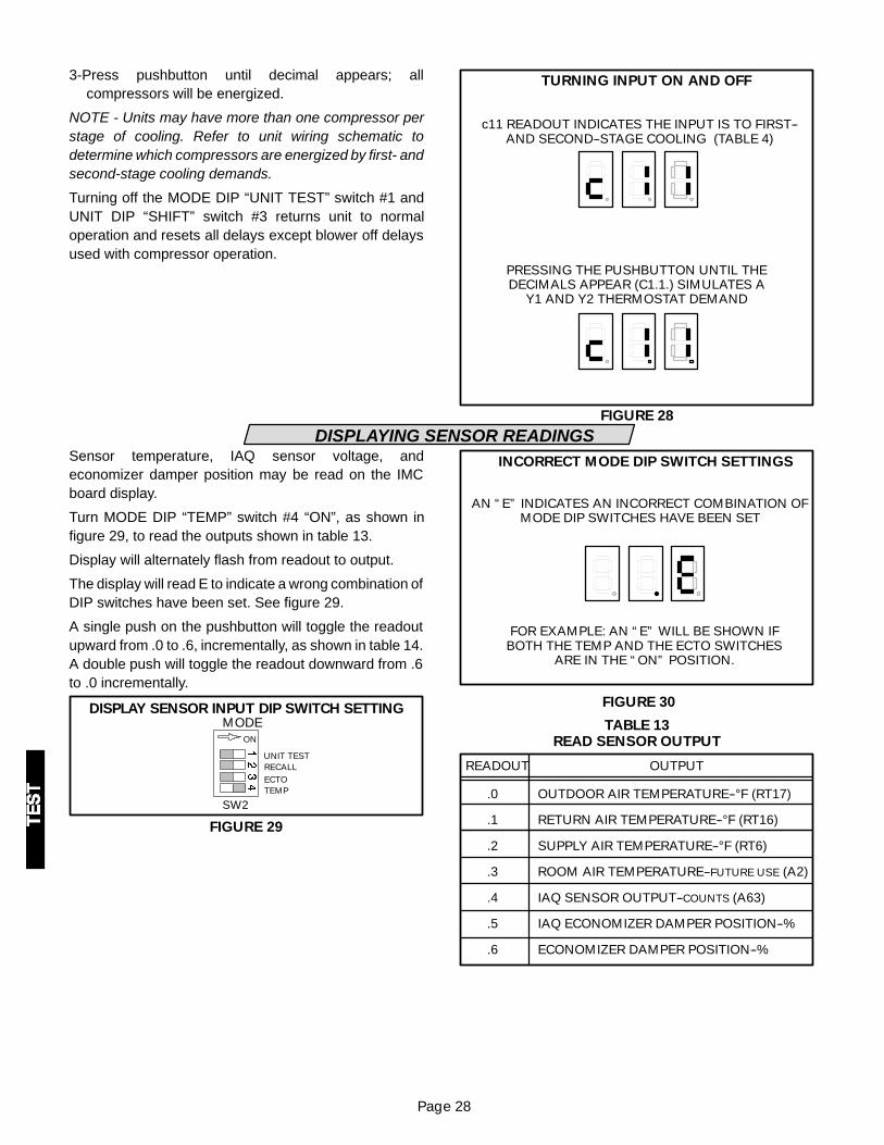
3-Press pushbutton until decimal appears; allcompressors will be energized.
NOTE - Units may have more than one compressor perstage of cooling. Refer to unit wiring schematic todetermine which compressors are energized by first- andsecond-stage cooling demands.
Turning off the MODE DIP “UNIT TEST” switch #1 andUNIT DIP “SHIFT” switch #3 returns unit to normaloperation and resets all delays except blower off delaysused with compressor operation.
TURNING INPUT ON AND OFF
FIGURE 28
c11 READOUT INDICATES THE INPUT IS TO FIRST--AND SECOND--STAGE COOLING (TABLE 4)
PRESSING THE PUSHBUTTON UNTIL THEDECIMALS APPEAR (C1.1.) SIMULATES A
Y1 AND Y2 THERMOSTAT DEMAND
DISPLAYING SENSOR READINGSSensor temperature, IAQ sensor voltage, andeconomizer damper position may be read on the IMCboard display.
Turn MODE DIP “TEMP” switch #4 “ON”, as shown infigure 29, to read the outputs shown in table 13.
Display will alternately flash from readout to output.
The display will read E to indicate a wrong combination ofDIP switches have been set. See figure 29.
A single push on the pushbutton will toggle the readoutupward from .0 to .6, incrementally, as shown in table 14.A double push will toggle the readout downward from .6to .0 incrementally.
DISPLAY SENSOR INPUT DIP SWITCH SETTING
FIGURE 29
SW2
ON
UNIT TESTRECALLECTOTEMP
MODE
INCORRECT MODE DIP SWITCH SETTINGS
FIGURE 30
AN “E” INDICATES AN INCORRECT COMBINATION OFMODE DIP SWITCHES HAVE BEEN SET
FOR EXAMPLE: AN “E” WILL BE SHOWN IFBOTH THE TEMP AND THE ECTO SWITCHES
ARE IN THE “ON” POSITION.
TABLE 13READ SENSOR OUTPUT
.0
.1
.2
.3
.4
.5
.6
READOUT OUTPUT
OUTDOOR AIR TEMPERATURE--°F (RT17)
RETURN AIR TEMPERATURE--°F (RT16)
SUPPLY AIR TEMPERATURE--°F (RT6)
ROOM AIR TEMPERATURE--FUTURE USE (A2)
IAQ SENSOR OUTPUT--COUNTS (A63)
IAQ ECONOMIZER DAMPER POSITION--%
ECONOMIZER DAMPER POSITION--%

Page 29
DEGREES CELSIUS (°C)
Change ECTO parameter 5.03 to option to display alltemperature in °C.
TEMPERATURE SENSORS
RT6 monitors supply air temperature. RT16 monitorsreturn air temperature. The main function of RT6 andRT16 is controlling the economizer. Both are also used fordiagnostic purposes.
RT17 monitors outdoor air temperature. RT17 is usedwhen controlling low ambient fan cycling, low ambientcompressor lockout, strike three control, high ambientstrip heat lockout, economizer control, and other controlfunctions.
Outdoor, return, supply, and zone air sensortemperatures are displayed to the nearest degree.
NOTE - RT6, RT16, and RT17 do not sense “enthalpy”,or total heat content of air.
Outdoor, return air, and supply air sensors arefactory-provided and installed. Zone air sensors arefield-provided and installed.
IAQ SENSOR OUTPUT VOLTAGE
IAQ sensors are field-provided and installed. Sensorsinterface with standard modulating economizers to bringin outdoor air when CO2 levels are high. The IAQ input iscompatible with IAQ sensors which have a 0-10VDCoutput and a CO2 range of 0-2000ppm.
Toggle pushbutton to .4 to read IAQ sensor output. Thedisplay will read between 0 and 255. Divide the readingby 25.5 to calculate the IAQ sensor output voltage.Multiply the reading by 7.843 to calculate the sensor CO2ppm.
Example:
1-Set MODE DIP “TEMP” switch #4 to “ON”.
2-Toggle pushbutton until .4 reading is alternatelyflashing with an output reading. Figure 31 shows anoutput reading of 100.
3-Divide output reading by 25.5 to get IAQ sensor outputvoltage. See figure 31.
IAQ SENSOR OUTPUT VOLTAGE EXAMPLE
FIGURE 31
DISPLAY READING ALTERNATES
100
25.5= 3.92 or 4 VOLT OUTPUT
100 X 7.843=784 ppm CO2
ECONOMIZER DAMPER POSITIONReadout .6 displays the damper motor feedback inpercent open. The feedback range for the economizermotor is 2-10vdc. Units with EM1 (A56) economizersoftware versions 1.02 and later board will display a rangeof 20-100% (20% is damper closed). Units with the EM1(A56) economizer software versions 1.00 and 1.01 willdisplay a range of 0-100% (0% is damper closed). Seetable 14.
000
13253850637588
100
TABLE 14DAMPER POSITION
0102030405060708090
100
READOUT % OPEN
0102030405060708090
100
(VER. 1.00 & 1.01) (VER. 1.02 AND UP)

Page 30
ELECTRONIC CONFIGURE TO ORDER (ECTO) CONTROL PARAMETERSMany IMC main control operations may be varied withina set range. Default settings are based on common oraverage applications; change ECTO settings only whencustom applications, preferences or local building codesexist. Default, minimum, and maximum range settingsare found in table 15.
READING CONTROL PARAMETERSControl parameters can be viewed using the pushbuttonand display. Set the MODE DIP “ECTO” switch #3 to “ON”to read the parameter which corresponds to a controlvalue. See figure 32.
DIP SWITCH ECTO SETTING
FIGURE 32
SW1
ON
HPGASSHIFT1PH
UNIT
“SHIFT” UNIT SWITCHDISPLAYS THE VALUE
SW2
ON
UNIT TESTRECALLECTOTEMP
MODE
“ECTO” SWITCH DISPLAYSTHE ECTO PARAMETER
The parameters are set up in five different blocks orgroups. The first digit of each parameter indicates theblock as follows:
1-LHA Heating Parameters2-LCA Heating Parameters3-LGA Heating Parameters4-Cooling Parameters5-Miscellaneous Parameters
A short push will move the display to the next parameter.A double push will move the display to the previousparameter. A long push will move the reading to the nextblock.
An IMC board with DIP switches set for an LGA unit willskip LHA block 1 and LCA block 2 readouts. An IMC boardwith DIP switches set for an LCA unit will skip LHA block1 and LGA block 3 readouts. An IMC board with DIPswitches set for an LHA unit will skip LCA block 2 and LGAblock 3 readouts.
CHANGING CONTROL VALUESControl values may be adjusted using the pushbutton anddisplay. Once the appropriate control parameter isdisplayed, turn on the UNIT DIP “SHIFT” switch #3 to readthe current ECTO value. See figure 32.
A short push will display the next value. A double push willdecrease the value by 10. A long push before returning tocontrol parameters (turning off SHIFT switch) will return
the value to the currently stored value. A long push willmove the reading to the next block and store the newECTO value. The value may also be stored by turning offthe SHIFT and ECTO DIP switches. The readout will turnoff and all decimals will turn on when new ECTOparameters are stored. The control also resets at thistime.
Control parameters are displayed in seconds, minutes,codes or number of counts. See table 16 to determineactual time or temperature span. Parameters may becalculated from counts using the following codecalculations.
CODE A: SECONDS = 2 x COUNTSCODE B: SECONDS = 4 x COUNTSCODE C: SECONDS = 8 x COUNTSCODE D: SECONDS = 32 x COUNTSCODE E: SECONDS = 128 x COUNTSCODE F: TEMP. (F) = 16 x COUNTSCODE W: TEMP. (F) = 0.25 x COUNTSCODE X: TEMP. (F) = 164.45 - (.6769 X COUNTS)CODE Y: TEMP. (F) = 131.56 - (.6360 x COUNTS)CODE Z: TEMP. (F) = 100- (.25 X COUNTS)
Change ECTO Summary:
1--Turn ECTO switch on.2--Pushbutton to desired parameter.
Short push advances parameter.Long push advances block.
3--Read present ECTO value with SHIFT switch.4--Change value with pushbutton.5--Turn off SHIFT switch. For multiple changes
repeat steps 2 through 5.6--Turn off ECTO and SHIFT switch.
Example:Use the following steps to increase compressorminimum-off delay interval.1-Set the MODE DIP “ECTO” switch #3 to “ON”.
2-With a long push on the pushbutton, move the controlparameter to the cooling block; the display will read“4.01”.
3-With short pushes of the pushbutton, toggle upwarduntil the readout displays “4.10”.
4-Set the UNIT DIP “SHIFT” switch #3 to “ON”.
5-The display will read “143.”. The ECTO Control ParameterTable (Table 15) shows a default of 143 counts or 300seconds. The table also shows a range of 29 counts(61seconds) to 255 counts (535 seconds).
6-To change the compressor minimum-off delay from 300seconds (5 minutes) to 360 seconds (6 minutes), refer toCode Conversion Table (Table 16 Column A) as shown in

Page 31
Control Parameter Table (Table 15) for number of countsto adjust control value to.
7-Short push the pushbutton until readout displays “172”.
8-To store the new ECTO control parameter, turn off theSHIFT and ECTO switch. The readout will turn off anddecimals will turn on. The control resets when newECTO parameters are stored (“8.8.8.” readout willflash).
RESET TO FACTORY ECTO PARAMETERSTo replace the factory ECTO parameters:1-Turn on the SHIFT switch.
2-Turn on the ECTO switch. On software version 1.03 andlater, also hold down the pushbutton for approximatelyfive seconds.
3-The display will read “---.” and then “0”.4-Turn off ECTO and DIP switches.
TABLE 15IMC ECTO CONTROL PARAMETERS
BLOCK 1 LHA HEATING PARAMETERSControl Parameter Control Value
Units DescriptionNo. Name Min Default Max.
Units Description
1.01 Warm-Up Delay2815
5630
255136
Code DMinutes
Warm-up time delay. The time that the supplemental heat is held offduring the first demand of warm-up. This parameter is only used if theparameter 1.17 is set to option 1.
1.02 Blower On Delay00
00
1560
Code BSeconds
Blower on delay. The time before the blower turns on after a heatingdemand.
1.03 Blower Off Delay00
520
75300
Code BSeconds
Blower off delay. The time the blower stays on after the heating demandis lost
1.04Max. Heating LimitOccurrences 1 5 15
Code BCounts
Service relay activation. Maximum Primary and Secondary Limit occur-rences stored before service relay is energized. If max value is set,service output is disabled.Note: Heating stage is not locked out.
1.05Supplemental HeatStage Delay
312
312
1560
Code BSeconds Time delay between 1 & 2 stage of supplemental heat.
1.06Supplemental Heat2 Lockout Tempera-ture
11360
16030
17520
Code YDeg. F
Temperature setpoint for lockout for the second bank of supplementalheat.Note: This parameter must be less than or equal to ECTO1.07.
1.07Supplemental Heat1 Lockout Tempera-ture
11360
14440
17520
Code YDeg. F
Temperature setpoint for lockout of first bank of supplemental heat.Note: This parameter must be equal to or greater than ECTO1.06.
1.08Compressor 1 LowTemperature Lock-out
8180
255Dis-
abled
254-30
Code YDeg. F
Low ambient lockout for compressor 1. 254 value equals -30 °F(-34°C). A value of 255 (-31°F) will disable low ambient lockout function.Note: This lockout is for heating only.
1.09Compressor 2 LowTemperature Lock-out
8180
255Dis-
abled
254-30
Code YDeg. F
Low ambient lockout for compressor 2. 254 value equals -30 °F(-34°C). A value of 255 (-31°F) will disable low ambient lockout func-tion. Note: This lockout is for heating only.
1.10Compressor Mini-mum Off Delay
3060
150300
255510
Code ASeconds
Compressor minimum off delay. Used on 1 PH units. Also used on allunits after an error occurs.
1.11Compressor Mini-mum Run Time
3060
120240
255510
Code ASeconds Compressor minimum run time. Used on 3 PH units.
1.12Max. High PressureOccurrences 1 3 8 Counts
Maximum High Pressure occurrences that are stored before controllocks off compressor stage and energizes the service relay. If max val-ue is set, service output is disabled.
1.13Max. Low PressureOccurrences 1 3 8 Counts
Maximum Low Pressure occurrences that are stored before controllocks off compressor stage and energizes the service relay. If max val-ue is set, service output is disabled.
1.14Defrost Supple-mental Heat Option 0 1 1 Option
Defrost options:0: No supplemental heating during defrost.1: Supplemental heating on during defrost.
1.15Minimum Time Be-tween Defrost
132
264
396
OptionMinutes
Minimum time allowed between defrost cycles.
1.16Maximum DefrostTime
210
315
525
CodeMinutes
Maximum defrost time allowed. Minutes = Value x 5.

Page 32
BLOCK 1 LHA HEATING PARAMETERSControl Parameter Control Value
Units DescriptionNo. Name Min Default Max.
Units Description
1.17 Warm-Up Options 0 0 2 Option
Warm-up mode option.0: Supplemental heat may be used during warm-up. Use depends onoutdoor temperature. See ECTO 1.06 and 1.07.1: For the first demand cycle, lockout supplemental heat for the first 30minutes (default). Time is adjustable by changing the parameterWARM-UP DLY # 1.01.2: For future use.
1.18Supplemental Heat1 Differential 0
082
153.75
Code WDeg. F
Supplemental heat stage 1differential. Used in zone sensor applications.Note: This parameter must be equal to or less than ECTO 1.19.
1.19Supplemental Heat2 Differential
00
123
153.75
zDeg. F
Supplemental heat stage 2 differential. Used in zone sensor applications.Note: This parameter must be equal to or greater than ECTO 1.18
1.20Supplemental Heat1Latch Option
0 0 1 OptionSupplemental heat stage 1 latch option. Used in zone sensor applications.0: Latch Disabled1: Latch Enabled
1.21Supplemental Heat2Latch Option
0 0 1 Option
Supplemental heat stage 2 latch option. Used in zone sensor applica-tions.0: Latch Disabled1: Latch Enabled
1.22Supplemental Heat1 Stage-Up Timer
00
00
22560
Code FMinutes
Supplemental heat stage 1 stage-up timer. The maximum time thatstage 1 runs before calling supplemental heat stage 1. Used in zonesensor applications.
1.23Supplemental Heat2 Stage-Up Timer
00
00
22560
Code FMinutes
Supplemental heat stage 2 stage-up timer. The maximum time thatsupplemental heat 1 runs before calling supplemental heat stage 2.Used in zone sensor applications.
1.24 Stage Down Timer00
5715
22560
Code FMinutes
Time delay before a lower stage turns off following a higher stage termi-nattion.
BLOCK 2 HEATING PARAMETERSControl Parameter Control Value
Units DescriptionNo. Name Min Default Max.
Units Description
2.01 Warm Up Delay00
11260
255136
Code DMinutes
Warm-up time delay. The time that the economizer is forced closedduring warm-up.
2.02 Blower On Delay00
00
00
Code BSeconds
Blower on delay. The time before the blower turns on after a heatingdemand. Reserved for future use
2.03 Blower Off Delay00
520
75300
Code BSeconds
Blower off delay. The time the blower stays on after the heating demandis lost
2.04Max. Heating LimitOccurrences 1 3 15 Counts
Service relay activation. Maximum Primary and Secondary Limit occur-rences stored before service relay is energized. If max value is set,service output is disabled. Note: Heating stage is not locked out
2.05 Heat Stage Delay312
312
1560
Code BSeconds Time delay between 1 & 2 stage of heat.
2.06Stage 2 Latch Op-tion 0 0 1 Option
Stage 2 latch option. Used in zone sensor applications.0: Latch Disabled1: Latch Enabled
2.07Stage 2 Stage-UpTimer
00
5715
22560
Code FMinutes
Stage 2 stage up timer. The maximum time that stage 1 runs beforecalling heat stage 2. Used in zone sensor applications.
2.08 Stage Down Timer00
5715
22560
Code FMinutes
Time delay before a lower stage turns off following a higher stage termi-nattion.
BLOCK 3 LGA HEATING PARAMETERS
Control Parameter Control ValueUnits Description
No. Name Min Default Max.Units Description
3.01 Warm Up Delay00
11260
255136
Code DMinutes
Warm-up time delay. The time that the economizer is forced closedduring warm-up.
3.02 Blower On Delay28
1040
1560
Code BSeconds
Blower on delay. The time before the blower turns on after a heatingdemand.

Page 33
BLOCK 3 LGA HEATING PARAMETERS
Control Parameter Control ValueUnits Description
No. Name Min Default Max.Units Description
3.03 Blower Off Delay2080
30120
75300
Code BSeconds
Blower off delay. The time the blower stays on after the heating demandis lost.
3.04Max. Heating LimitOccurrences 1 3 15 Counts
Service relay activation. Maximum Primary and Secondary Limit occur-rences stored before service relay is energized. If max value is set,service output is disabled.Note: Heating stage is not locked out.
3.05 High Fire Delay1530
1530
80160
Code ASeconds The minimum low fire time before high fire is allowed.
3.06 Heating Off Delay1530
50100
150300
Code ASeconds Heating off delay.
3.07Max. CombustionAir Proof Switch Oc-currences
1 3 6 CountsService relay activation. Maximum Combustion Air Blower Proof Switchoccurrences stored before service relay is energized. If max value isset, service output is disabled. Note: Heating stage is not locked out.
3.08Max. Roll OutSwitch Occurrences 1 1 4 Counts
Service relay activation. Maximum Roll Out Switch occurrences storedbefore service relay is energized. If max value is set, service outputdisabled.Note: Heating stage is not locked out.
3.09Max. Gas ValveSense Occurrences 1 3 6 Counts
Service relay activation. Maximum Gas Valve Sense occurrencesstored before service relay is energized. If max value is set, serviceoutput is disabled. Note: Heating stage is not locked out.
3.10Stage 2 Latch Op-tion 0 0 1 Option
Stage 2 latch option. Used in zone sensor applications.0: Latch Disabled 1: Latch Enabled
3.11Stage 2 Stage-UpTimer
00
5715
22560
Code FMinutes
Stage 2 stage-up timer. The maximum time that stage 1 runs beforecalling heat stage 2. Used in zone sensor applications.
3.12 Stage Down Timer00
5715
22560
Code FMinutes
Time delay before a lower stage turns off following a higher stage termi-nattion.
BLOCK 4 COOLING PARAMETERS
Control Parameter Control ValueUnits Description
No. Name Min Default Max.Units Description
4.01 Cool Down Delay00
5630
255136
Code DMinutes
Cool down delay. Time that Y2 is ignored after night setback. This delayis only used if an economizer is used and the outdoor air is suitable.
4.02 Blower On Delay00
00
1560
Code BSeconds
Blower on delay. The time before the blower turns on after a coolingdemand.
4.03 Blower Off Delay00
00
60240
Code BSeconds
Blower off delay. The time the blower stays on after the cooling demandis lost.
4.04Max. Freeze StatOccurrences 1 3 4 Counts
Service relay activation. Maximum Freeze Stat occurrences storedbefore service relay is energized. If max value is set, service output isdisabled. Note: The cooling stage is not locked out.
4.05 Fan Re-Start Delay00
36
816
Code ASeconds
Low ambient anti--windmilling fan delay. The time period that the lastoperating fan is turned off before starting the next fan.
4.06Low Ambient Set-point Temp. 1
11360
14440
19110
Code YDeg. F
Low ambient outdoor air limit temp. 1. Parameters 4.06 and 4.07 areused to shed fans. See Operation section.
4.07Low Ambient Set-point Temp. 2
11360
12055
19110
Code YDeg.F
Low ambient outdoor air limit temp. 2. Parameters 4.06 and 4.07 areused to shed fans. See Operation section.
4.08Compressor 1 LowTemperature Lock-out
8180
2070
254-30
Code YDeg. F
Low ambient lockout for compressor 1. 254 value equals -30 °F(-34°C). A value of 255 (-31°F) will disable low ambient lockout func-tion. Parameter value must be less than or equal to 4.09.
4.09Compressor 2 LowTemperature Lock-out
8180
2070
254-30
Code YDeg. F
Low ambient lockout for compressor 2. 254 value equals -30 °F(-34°C). A value of 255 (-31°F) will disable low ambient lockout func-tion. Parameter value must be equal to or greater than 4.08 .
4.10Compressor 3 LowTemperature Lock-out
8180
2070
254-30
Code YDeg. F
Low ambient lockout for compressor 3. 254 value equals -30 °F(-34°C). A value of 255(-31°F) will disable low ambient lockout func-tion. Parameter value must be equal to or greater than 4.08 and4.09.

Page 34
BLOCK 4 COOLING PARAMETERS
Control Parameter Control ValueUnits Description
No. Name Min Default Max.Units Description
4.11Compressor 4 LowTemperature Lock-out
8180
2070
254-30
Code YDeg. F
Low ambient lockout for compressor 4. 254 value equals -30 °F(-34°C). A value of 255 (-31°F) will disable low ambient lockout function. Parameter value must be equal to or greater than 4.10, 4.09 and4.08.
4.12Compressor Mini-mum Off Delay
3060
150300
255510
Code ASeconds
Compressor minimum off delay. Used on 1 PH units. Also used on allunits after an error occurs.
4.13Compressor Mini-mum Run Time
3060
120240
255510
Code ASeconds Compressor minimum run time. Used on 3 PH units.
4.14Max. High PressureOccurrences 1 3 8 Counts
Maximum High Pressure occurrences that are stored before controllocks off compressor stage and energizes the service relay. If max val-ue is set, service output is disabled.
4.15Max. Low PressureOccurrences 1 3 8 Counts
Maximum Low Pressure occurrences that are stored before controllocks off compressor stage and energizes the service relay. If max val-ue is set, service output is disabled.
4.16Condenser FanDelay
00
12
120240
Code ASeconds Condenser fan delay. Used only on 25 & 30 ton units.
4.17Stage 2 LatchOption
0 0 1 OptionStage 2 latch option. Used in zone sensor applications.0: Latch Disabled1: Latch Enabled
4.18Stage 3 LatchOption
0 0 1 OptionStage 3 latch option. Used in zone sensor applications.0: Latch Disabled1: Latch Enabled
4.19Stage 4 LatchOption
0 0 1 OptionStage 4 latch option. Used in zone sensor applications.0: Latch Disabled1: Latch Enabled
4.20Stage 2 Stage-UpTimer
00
5715
22560
Code FMinutes
Stage 2 stage up timer. The maximum time that cooling stage 1 runsbefore calling cooling stage 2. Used in zone sensor applications.
4.21Stage 3 Stage-UpTimer
00
5715
22560
Code FMinutes
Stage 3 stage up timer. The maximum time that cooling stage 2 runsbefore calling cooling stage 3. Used in zone sensor applications.
4.22Stage 4 Stage-UpTimer
00
5715
22560
Code FMinutes
Stage 4 stage up timer. The maximum time that cooling stage 3 runsbefore calling cooling stage 4. Used in zone sensor applications.
4.23 Stage Down Timer00
5715
22560
Code FMinutes
Stage down timer. Used in zone sensor applications.
4.24Reheat Control Op-tion 0 0 1 Option
Supermarket reheat option. Allows for simultaneous heating and cool-ing based on the limitations outlined in Operation section.
BLOCK 5 MISCELLANEOUS PARAMETERS
Control Parameter Control ValueUnits Description
No. Name Min Default Max.Units Description
5.01Smoke AlarmOption 0 0 3 Option
Operation options if smoke alarm occurs.0: Unit off1: Blower on, Exhaust Fan off, Outdoor Air Damper open (Positivepressure)2: Blower on, Exhaust Fan off, Outdoor Air Damper closed (Negativepressure)3: Blower on, Exhaust Fan on, Outdoor Air Damper open (Purge)
5.02Error Timed OffDelay
81
385
22530
Code CMinutes
Off time delay if a “no-run” error occurs.
5.03Celsius Tempera-ture Option 0 0 1 Option
Degrees Celsius option.0: Displays degrees Fahrenheit1: Displays degrees Celsius

Page 35
BLOCK 5 MISCELLANEOUS PARAMETERS
Control Parameter Control ValueUnits Description
No. Name Min Default Max.Units Description
5.04Thermostat StagingOptions 1 2 3 Option
Staging option for thermostat input..1: Two cooling stages. Units with Economizers Y1=Free Cooling,Y2=adds all mechanical stages.2: Two cooling stages. Units with Economizers Y1=Free Cooling, Y2=adds first stage of mechanical.3: Three cooling stages. Y1 only = first stage, Y2 only = second stage,Y1+Y2 = third stage. Units with Economizers Y2 only adds first stage ofmechanical, Y1+Y2 adds first and second stage of mechanical.See operation section for more information.
5.05Return Air Temp.Limit Option 0 0 1 Option
Return air temperature limit option enable. Set to 1 to use 5.06 or5.07. Return air limits may be used for limiting zone temperatures.
5.06Return Air Temp.Heating Limit
95100
95100
12480
Code XDeg. F
Return air limit for heating. 5.05 MUST BE SET TO 1 TO ENABLE. If thereturn air heating limit is exceeded, the heating demands are interrupted.
5.07Return Air Temp.Cooling Limit
12480
15460
15460
Code XDeg. F
Return air limit for cooling. 5.05 MUST BE SET TO 1 TO ENABLE. If thereturn air cooling limit is exceeded, the cooling demands are interrupted.
5.08A42 Input Occur-rences 1 3 15 Counts A42 input occurrences before service relay is energized. (PI10-9)
5.09Exhaust Fan OnSetpoint 0 50 100
% DamperTravel
This parameter determines when the exhaust fan is energized. Thedefault of 50 means that the exhaust fan will turn on when the econo-mizer damper is at 50% travel.
5.10Low Pressure StrikeThree Run Time 1
00
608
25534
Code CMinutes
Ignore LP trip when compressor run time less than this. LONG/HOTcondition. See chart 1 in Operation section.
5.11Low Pressure StrikeThree Run Time 2
00
11315
25534
Code CMinutes
Ignore LP trip when compressor run time less than this. LONG/COLDcondition. See chart 1 in Operation section.
5.12Low Pressure StrikeThree Run Time 3
00
152
25534
Code CMinutes
Ignore LP trip when compressor run time less than this. SHORT/HOTcondition. See chart 1 in Operation section.
5.13Low Pressure StrikeThree Run Time 4
00
385
25534
Code CMinutes
Ignore LP trip when compressor run time less than this. SHORT/ COLDcondition. See chart 1 in Operation section.
5.14Low Pressure StrikeThree Off Time
281
1134
1696
Code EHours Compressor off time breakpoint for LONG/SHORT evaluation.
5.15Low Pressure StrikeThree Temp. Setpoint
50100
9770
19110
Code YDeg.F
Outdoor air temperature breakpoint for HOT/COLD evaluation. Seechart 1 in Operation section.
5.16IAQO - Max. Damp-er Open 0 100 100 % Travel Maximum allowed IAQ damper open. (Set to 0 to disable IAQ)
5.17IAQ 1 - DamperStart Open Setpoint
00
64500
2551992
PPM Damper ”start open” IAQ setpoint. CO2 level (ppm) where economizerdamper begins to open.
5.18IAQ2 - Damper FullOpen Setpoint
00
1281000
2551992
PPMDamper ”full open” IAQ setpoint. CO2 level (ppm) where economizerdamper is opened to maximum.
5.19IAQ 3 - Damper FullClosed Setpoint
0132
19110
255-31
Code YDeg.F Low outdoor air temp. where IAQ damper is completely closed.
5.20IAQ 4 - Low Temp.Start Closing
0132
14440
255-31
Code YDeg.F
Low outdoor air temp. where IAQ damper begins to close. Set IAQ 4 =255 and IAQ 5 = 0 to disable the outdoor tempering of IAQ operation.
5.21IAQ 5 - High Temp.Start Closing
0132
8975
255-31
Code YDeg.F
High outdoor air temp. where IAQ damper begins to close. Set IAQ 4 =255 and IAQ 5 = 0 to disable the outdoor tempering of IAQ operation.
5.22IAQ 6 - High Temp.Full Close
0132
42105
255-31
Code YDeg.F High outdoor air temp. where IAQ damper is completely closed.
5.23Free Cooling Max.Damper 0 100 100 % Travel The maximum allowed damper opening for FREE COOLING.
5.24Economizer GlobalOption 0 0 1 Option
Global control option.0: Free Cooling when Global input is present1: Global input absent -- Damper position = Minimum Damper Setpoint(Set on A56)
Global input present -- Damper position = Maximum Damper Set-point (ECTO 5.23)Available only on economizer (A56) board software versions 1.07+

Page 36
BLOCK 6 SYSTEM PARAMETERS
Control Parameter Control ValueUnits Description
No. Name Min Default Max.Units Description
6.01 System Mode 0 0 11 Option
System mode of operation.Control Value Control Mode Backup Mode
0 Local Thermostat None1 IMC Zone Sensor None2 IMC Zone Sensor Local Thermostat3 IMC Zone Sensor Return Air Sensor4 Remote Demand None5 Remote Demand Local Thermostat6 Remote Demand Return Air Sensor7 Remote Demand IMC Zone Sensor8 Direct None9 Direct Local Thermostat10 Direct Return Air Sensor11 Direct IMC Zone Sensor
6.02Occupied HeatingBackup Setpoint
6085
12070
18055
Code ZDeg. F
Backup occupied heating setpoint. Used if the communications link islost between the IMC and the EMS. Used only with IMC zone sensorapplications.
6.03Unoccupied HeatingBackup Setpoint
6085
16060
18055
Code ZDeg. F
Backup unoccupied heating setpoint. Used if the communications linkis lost between the IMC and the EMS. Used only with IMC zone sensorapplications
6.04Occupied CoolingBackup Setpoint
6085
10075
18055
Code ZDeg. F
Backup occupied cooling setpoint. Used if the communications link islost between the IMC and the EMS. Used only with IMC zone sensorapplications.
6.05Unoccupied CoolingBackup Setpoint
6085
6085
18055
Code ZDeg. F
Backup unoccupied cooling setpoint. Used if the communications linkis lost between the IMC and the EMS. Used only with IMC zone sensorapplications.
6.06Night Setback Over-ride Timer
00
281
2258
Code EHours
Night setback override timer. Used with IMC zone sensor applications.
6.07 Heating Deadband41
41
153.75
Code WDeg. F
Heating deadband . Used only with IMC zone sensor applications.
6.08 Cooling Deadband41
41
153.75
Code WDeg. F
Cooling deadband. Used only with zone sensor applications.
6.09Stage 1 HeatingDifferential
00
20.5
123
Code WDeg. F
Heating stage 1 differential. Used only with IMC zone sensor applications.
6.10Stage 1 CoolingDifferential
00
20.5
123
Code WDeg. F
Cooling stage 1 differential. Used only with IMC zone sensor applications.
6.11Stage 2 HeatingDifferential
00
41
123
Code WDeg. F
Heating stage 2 differential. Used only with IMC zone sensor applications.
6.12Stage 2 CoolingDifferential
00
20.5
123
Code WDeg. F
Cooling stage 2 differential. Used only with IMC zone sensor applications.
6.13Stage 3 CoolingDifferential
00
41
123
Code WDeg. F
Cooling stage 3 differential. Used only with IMC zone sensor applications.
6.14Stage 4 CoolingDifferential
00
41
123
Code WDeg. F
Cooling stage 4 differential. Used only with IMC zone sensor applications.
6.15AutochangeoverDeadband
164
164
4010
Code WDeg. F
Autochangeover deadband temperature. Used only with IMC zone sen-sor applications.
6.16AutochangeoverDelay
151
755
22515
Code BMinutes
Autochangeover time delay. Used only with IMC zone sensor applications.
6.17 Blower Control 0 0 1 CountsBlower control option for IMC zone sensor applications. (During occupied)0 = Blower cycles with demands1 = Continuous blower
6.18IMC Zone SensorCalibration
205
00
236-5
CodeDeg. F
IMC zone sensor calibration offset.Code : 20 16 12 8 4 0 252 248 244 240 236Offset +5 +4 +3 +2 +1 0 -1 -2 -3 -4 -5 (Deg. F)

Page 37
Convert number of counts displayed to length of time or temperature:CODE A: SECONDS = 2 x COUNTSCODE B: SECONDS = 4 x COUNTSCODE C: SECONDS = 8 x COUNTSCODE D: SECONDS = 32 x COUNTSCODE E: SECONDS = 128 x COUNTS
CODE F: TEMP. (F) = 16 x COUNTSCODE W: TEMP. (F) = 0.25 x COUNTSCODE X: TEMP. (F) = 164.45 - (.6769 x COUNTS)CODE Y: TEMP. (F) = 131.56 - (.6360 x COUNTS)CODE Z: TEMP. (F) = 100 - (.25 X Counts)
TABLE 16ECTO PARAMETER CODE CONVERSION TABLE
Count Time Temperature
A B C D E F W X Y Z
Sec. Sec. Sec. Sec. Sec. Sec. °F °C °F °C °F °C °F °C
0 0 0 0 0 0 0 0 0 164 74 132 55.3 100 37.8
5 10 20 40 160 640 80 1 0.7 161 72 128 53.5 99 37.1
10 20 40 80 320 1280 160 3 1.4 158 70 125 51.8 98 36.4
15 30 60 120 480 1920 240 4 2.1 154 68 122 50.0 96 35.7
20 40 80 160 640 2560 320 5 2.8 151 66 119 48.2 95 35.0
25 50 100 200 800 3200 400 6 3.5 148 64 116 46.5 94 34.3
30 60 120 240 960 3840 480 8 4.1 144 62 112 44.7 93 33.6
35 70 140 280 1120 4480 560 9 4.8 141 60 109 42.9 91 32.9
40 80 160 320 1280 5120 640 10 5.5 137 59 106 41.2 90 32.3
45 90 180 360 1440 5760 720 11 6.2 134 57 103 39.4 89 31.6
50 100 200 400 1600 6400 800 13 6.9 131 55 100 37.6 88 30.9
55 110 220 440 1760 7040 880 14 7.6 127 53 97 35.9 86 30.2
60 120 240 480 1920 7680 960 15 8.3 124 51 93 34.1 85 29.5
65 130 260 520 2080 8320 1040 16 9.0 120 49 90 32.3 84 28.8
70 140 280 560 2240 8960 1120 18 9.7 117 47 87 30.6 83 28.1
75 150 300 600 2400 9600 1200 19 10.4 114 45 84 28.8 81 27.4
80 160 320 640 2560 10240 1280 20 11.0 110 44 81 27.0 80 26.7
85 170 340 680 2720 10880 1360 21 11.7 107 42 78 25.3 79 26.0
90 180 360 720 2880 11520 1440 23 12.4 104 40 74 23.5 78 25.4
95 190 380 760 3040 12160 1520 24 13.1 100 38 71 21.7 76 24.7
100 200 400 800 3200 12800 1600 25 13.8 97 36 68 20.0 75 24.0
105 210 420 840 3360 13440 1680 26 14.5 93 34 65 18.2 74 23.3
110 220 440 880 3520 14080 1760 28 15.2 90 32 62 16.4 73 22.6
115 230 460 920 3680 14720 1840 29 15.9 87 30 58 14.7 71 21.9
120 240 480 960 3840 15360 1920 30 16.6 83 28 55 12.9 70 21.2
125 250 500 1000 4000 16000 2000 31 17.3 80 27 52 11.1 69 20.5
130 260 520 1040 4160 16640 2080 33 17.9 76 25 49 9.4 68 19.8
135 270 540 1080 4320 17280 2160 34 18.6 73 23 46 7.6 66 19.1
140 280 560 1120 4480 17920 2240 35 19.3 70 21 43 5.8 65 18.5
145 290 580 1160 4640 18560 2320 36 20.0 66 19 39 4.1 64 17.8
150 300 600 1200 4800 19200 2400 38 20.7 63 17 36 2.3 63 17.1
155 310 620 1240 4960 19840 2480 39 21.4 60 15 33 0.5 61 16.4
160 320 640 1280 5120 20480 2560 40 22.1 56 13 30 -1.2 60 15.7

Page 38
Count Time Temperature
A B C D E F W X Y Z
Sec. Sec. Sec. Sec. Sec. Sec. °F °C °F °C °F °C °F °C
165 330 660 1320 5280 21120 2640 41 22.8 53 12 27 -3.0 59 15.0
170 340 680 1360 5440 21760 2720 43 23.5 49 10 23 -4.8 58 14.3
175 350 700 1400 5600 22400 2800 44 24.2 46 8 20 -6.5 56 13.6
180 360 720 1440 5760 23040 2880 45 24.8 43 6 17 -8.3 55 12.9
185 370 740 1480 5920 23680 2960 46 25.5 39 4 14 -10.1 54 12.2
190 380 760 1520 6080 24320 3040 48 26.2 36 2 11 -11.8 53 11.6
195 390 780 1560 6240 24960 3120 49 26.9 32 0 8 -13.6 51 10.9
200 400 800 1600 6400 25600 3200 50 27.6 29 -2 4 -15.4 50 10.2
205 410 820 1640 6560 26240 3280 51 28.3 26 -4 1 -17.1 49 9.5
210 420 840 1680 6720 26880 3360 53 29.0 22 -5 -2 -18.9 48 8.8
215 430 860 1720 6880 27520 3440 54 29.7 19 -7 -5 -20.6 46 8.1
220 440 880 1760 7040 28160 3520 55 30.4 16 -9 -8 -22.4 45 7.4
225 450 900 1800 7200 28800 3600 56 31.1 12 -11 -12 -24.2 44 6.7
230 460 920 1840 7360 29440 3680 58 31.7 9 -13 -15 -25.9 43 6.0
235 470 940 1880 7520 30080 3760 59 32.4 5 -15 -18 -27.7 41 5.3
240 480 960 1920 7680 30720 3840 60 33.1 2 -17 -21 -29.5 40 4.7
245 490 980 1960 7840 31360 3920 61 33.8 -1 -19 -24 -31.2 39 4.0
250 500 1000 2000 8000 32000 4000 63 34.5 -5 -20 -27 -33.0 38 3.3
255 510 1020 2040 8160 32640 4080 64 35.2 -8 -22 -31 -34.8 36 2.6

Page 39
IMC BOARD INPUTS AND OUTPUTSWhen necessary, individual inputs and outputs maybe read at the IMC board connectors. IMC boards areshown on wiring diagrams as dashed boxes. Seeshaded areas in figure 33. Parts of the IMC boards willbe located in all wiring diagram sections. See figure34 to find the jack/plug connector on the IMC board(s).Use table 17 in this section for a description of eachpin number, a description of the input or output, andthe type of input or output.
Example:
To determine if 24 volts is being supplied to the K3blower contactor:
1--Using the unit wiring diagram and figure 34, locateK3 and identify appropriate IMC board andjack/plug. (A55 main board and J/P113--11.)
2--Find the I&O table for P113. Pin 11 shows a 24 voltoutput to the blower.
TYPICAL LGA OR LCA UNIT SCHEMATIC (17-1/2 & 20 TON)
FIGURE 33
SHADED AREAS INDICATE IMC BOARD
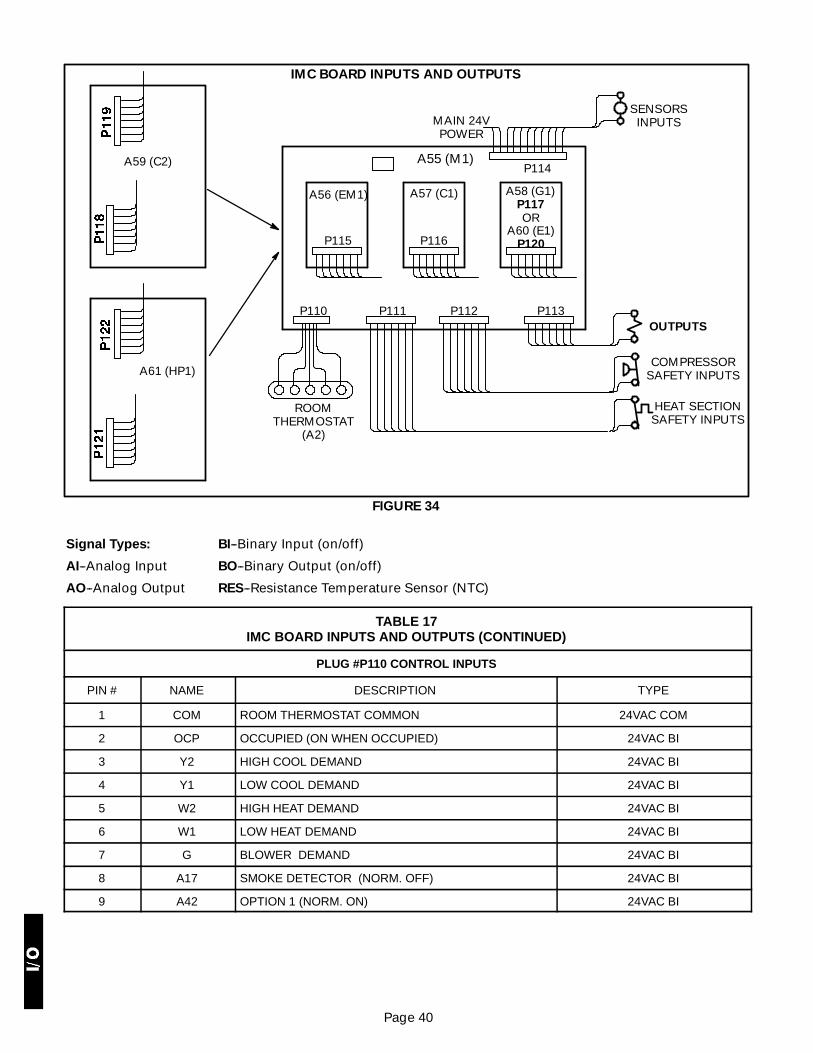
Page 40
IMC BOARD INPUTS AND OUTPUTS
FIGURE 34
P110 P111 P112 P113
P114
P115 P116
SENSORSINPUTS
OUTPUTS
COMPRESSORSAFETY INPUTS
HEAT SECTIONSAFETY INPUTS
ROOMTHERMOSTAT
(A2)
A55 (M1)
A56 (EM1) A57 (C1) A58 (G1)P117
A60 (E1)P120
A59 (C2)
A61 (HP1)
OR
MAIN 24VPOWER
Signal Types:
AI--Analog Input
AO--Analog Output
BI--Binary Input (on/off)
BO--Binary Output (on/off)
RES--Resistance Temperature Sensor (NTC)
TABLE 17IMC BOARD INPUTS AND OUTPUTS (CONTINUED)
PLUG #P110 CONTROL INPUTS
PIN # NAME DESCRIPTION TYPE
1 COM ROOM THERMOSTAT COMMON 24VAC COM
2 OCP OCCUPIED (ON WHEN OCCUPIED) 24VAC BI
3 Y2 HIGH COOL DEMAND 24VAC BI
4 Y1 LOW COOL DEMAND 24VAC BI
5 W2 HIGH HEAT DEMAND 24VAC BI
6 W1 LOW HEAT DEMAND 24VAC BI
7 G BLOWER DEMAND 24VAC BI
8 A17 SMOKE DETECTOR (NORM. OFF) 24VAC BI
9 A42 OPTION 1 (NORM. ON) 24VAC BI

Page 41
TABLE 17IMC BOARD INPUTS AND OUTPUTS (CONTINUED)
PLUG #P111 HEAT SAFETY
PIN # NAME DESCRIPTION TYPE
1 S10-C PLT1-C (PRI. LIMIT 1) SW (24VAC)
2 S10-NC PLT1-NC (PRI. LIMIT1)
3 S10-NO PLT1-NO (PRI. LIMIT1)
4 S21-C SLT1-C (SEC. LIMIT1) SW (24VAC)
5 S21-NC SLT1-NC (SEC. LIMIT1)
6S47 ROS1 (ROLL OUT SWITCH 1) SW (24VAC)
7S47 ROS1 (ROLL OUT SWITCH 1) SW (24VAC)
8S18 CAB1(COMB. AIR PROOF 1 SWITCH) SW (24VAC)
9S18 CAB1(COMB. AIR PROOF 1 SWITCH) SW (24VAC)
10 GV1 GV1 (GAS VALVE 1 SENSE) 24VAC BI
11 TB35-1 24 VAC (FOR HEATING OUTPUTS & BLOWER) 24VAC POWER
12 TB35-2 RETURN (FOR TRANS. PROT.) 24VAC POWER
PLUG #P112 COOLING SAFETY
1S87 LP1 (LOW PRESS. 1) SW (24VAC)
2S87 LP1 (LOW PRESS. 1) SW (24VAC)
3S4 HP1 (HIGH PRESS. 1) SW (24VAC)
4S4 HP1 (HIGH PRESS. 1) SW (24VAC)
5S49 FRZ1 (FREEZE STAT 1) SW (24VAC)
6S49 FRZ1 (FREEZE STAT 1) SW (24VAC)
7S6 DFT1 (DEF. TEMP. STAT 1) SW (24VAC)
8S6 DFT1 (DEF. TEMP. STAT 1) SW (24VAC)
9S46 DFP1 (DEF. PRESS. 1) SW (24VAC)
10S46 DFP1 (DEF. PRESS. 1) SW (24VAC)
11S27 DFS (DIRTY FILTER SWITCH) SW (24VAC)
12S27 DFS (DIRTY FILTER SWITCH) SW (24VAC)
13S52 AFS (AIR FLOW SWITCH) SW (24VAC)
14S52 AFS (AIR FLOW SWITCH) SW (24VAC)
PLUG #P113 OUTPUTS
1 TB34-1 24VAC (FOR RELAY OUTS) 24VAC POWER
2 TB34-2 RETURN (FOR TRANS. PROT.) 24VAC POWER
3 SR SERVICE. RELAY (24VAC OUT) 24VAC BO
4 K1-A COMPRESSOR 1 24VAC BO
5 K10-A FAN 1 24VAC BO
6 S11LOW PRESS. (LOW AMB. CONTROL FAN 1) SW (24VAC)
7 S11LOW PRESS. (LOW AMB. CONTROL FAN 1) SW (24VAC)
8 L1 RV1 (REVERSING VALVE 1) 24VAC BO
9 K13-A CAB 1 (COMBUSTION AIR BLOWER RELAY 1) 24 VAC BO
10 W2 H2/E2 (HEAT2/ELECTRIC HEAT 2) 24 VAC BO
11 K3-A BLOWER 24 VAC BO
12 A3-1 H1/E1 (HEAT1/ ELECTRIC HEAT 1) 24 VAC BO

Page 42
TABLE 17IMC BOARD INPUTS AND OUTPUTS (CONTINUED)
PLUG #P114 ANALOG INPUTS
PIN # NAME DESCRIPTION TYPE
1 TB34-2 COMMON (FOR MAIN CONTROL) 24VAC POWER
2 TB34-1 24VAC (FOR MAIN CONTROL) 24VAC POWER
3 A2ZONE SENSOR RES (0-5VDC)
4 A2ZONE SENSOR RES (0-5VDC)
5 RT16RAT (RETURN AIR TEMP) RES (0-5VDC)
6 RT16RAT (RETURN AIR TEMP) RES (0-5VDC)
7 RT6 DAT (DISCHARGE AIR TEMP) RES (0-5VDC)
8 RT6 DAT (DISCHARGE AIR TEMP) RES (0-5VDC)
9 RT11RESERVED RES (0-5VDC)
10 RT11RESERVED RES (0-5VDC)
11 A63IAQ (INDOOR AIR QUALITY ) 0-10VDC AI
12 A63IAQ (INDOOR AIR QUALITY ) 0-10VDC AI
13 RT17OAT (OUTDOOR AMB. TEMP)
RES (0-5VDC)
14 RT17OAT (OUTDOOR AMB. TEMP)
PLUG #P115 A56 EM1 ECONOMIZER BOARD
1 TB34-2 COMMON 24 VAC POWER
2 VOT DAMPER CONTROL 0-10 VDC A0
3 K65 EXHAUST FAN 24VAC BO
4 GLO GLOBAL CONTROL INPUT 24VAC BI
5 A62 + INDOOR ENTHALPY SENSOR4-20mA AI
6 A62 SINDOOR ENTHALPY SENSORHONEYWELL C7400A 4-20mA AI
7 A7 + OUTDOOR ENTHALPY SENSOR4-20 mA AI
8 A7 SOUTDOOR ENTHALPY SENSORHONEYWELL C7400A 4-20 mA AI
9 DPOS DAMPER POSITION FEEDBACK 0-10VDC AI
PLUG #P116 A57 C1
1 TB34-2 RETURN (FOR TRANS. PROT.) COM (24VAC)
2 S84LOW PRESS (LOW AMB. CONTROL, FAN 2) SW (24VAC)
3 S84LOW PRESS (LOW AMB. CONTROL, FAN 2) SW (24VAC)
4 K68 FAN 2 24VAC BO
5 K2 COMPRESSOR 2 24VAC BO
6 S7HP2 (HIGH PRESS. 2) SW (24VAC)
7 S7HP2 (HIGH PRESS. 2) SW (24VAC)
8 S50FRZ2 (FREEZE STAT 2) SW (24VAC)
9 S50FRZ2 (FREEZE STAT 2) SW (24VAC)
10 S88LP2 (LOW PRESS. 2) SW (24VAC)
11 S88LP2 (LOW PRESS. 2) SW (24VAC)
12 RT13RESERVED RES (0-5VDC)
13 RT13RESERVED RES (0-5VDC)

Page 43
TABLE 17IMC BOARD INPUTS AND OUTPUTS (CONTINUED)
PLUG #P117 A58 G1 BOARD
PIN # NAME DESCRIPTION TYPE
1 TB35-1 24VAC IN 24VAC POWER
2 TB35-2 RETURN (FOR TRANS. PROT.) 24VAC POWER
3 K19-A CAB2 (COMBUSTION AIR BLOWER RELAY 2) 24VAC BO
4 W2 H4 (HEAT 4) 24VAC BO
5 A12-1 H3 (HEAT 3) 24VAC BO
6 S99-C PLT2-C (PRI. LIMIT2) SW (24VAC)
7 S99-NC PLT2-NC(PRI. LIMIT2)
8 S100-C SLT2-C (SEC. LIMIT2) SW (24VAC)
9 S100-NC SLT2-NC (SEC. LIMIT2)
10 S69ROS2 (ROLL OUT SWITCH2) SW (24VAC)
11 S69ROS2 (ROLL OUT SWITCH2) SW (24VAC)
12 S45CAB2 (COMB. AIR PROOF 2 SWITCH) SW (24VAC)
13 S45CAB2 (COMB. AIR PROOF 2 SWITCH) SW (24VAC)
14 GV2 GV2 (GAS VALVE 2 SENSE) 24VAC BI
PLUG #P118 A59 C2 BOARD
1 TB35-1 24VAC 24VAC POWER
2 TB35-2 COMMON 24VAC POWER
3 S11LOW PRESS (LOW AMB. , FAN 3) SW (24VAC)
4 S11LOW PRESS (LOW AMB. , FAN 3) SW (24VAC)
5 K149 FAN 3 24VAC BO
6 S85LOW PRESS (LOW AMB., FAN 4) SW (24VAC)
7 S85LOW PRESS (LOW AMB., FAN 4) SW (24VAC)
8 K150 FAN 4 24VAC BO
9 K152 FAN 5 24VAC BO
10 K153 FAN 6 24VAC BO
11 K14 COMPRESSOR 3 24VAC BO
12 K146 COMPRESSOR 4 24VAC BO
15 RT14RESERVED RES (0-5 VDC)
16 RT14RESERVED RES (0-5 VDC)

Page 44
TABLE 17IMC BOARD INPUTS AND OUTPUTS (CONTINUED)
PLUG #P119 COMPRESSOR SAFETY
PIN # NAME DESCRIPTION TYPE
1 S28HP3 (HIGH PRESS. 3) SW (24VAC)
2 S28HP3 (HIGH PRESS. 3) SW (24VAC)
3 S96HP4 (HIGH PRESS. 4) SW (24VAC)
4 S96HP4 (HIGH PRESS. 4) SW (24VAC)
5 S53FRZ3 (FREEZE STAT 3) SW (24VAC)
6 S53FRZ3 (FREEZE STAT 3) SW (24VAC)
7 S98LP3 (LOW PRESS. 3) SW (24VAC)
8 S98LP3 (LOW PRESS. 3) SW (24VAC)
9 S95FRZ4 (FREEZE STAT 4) SW (24VAC)
10 S95FRZ4 (FREEZE STAT 4) SW (24VAC)
11 S97LP4 (LOW PRESS. 4) SW (24VAC)
12 S97LP4 (LOW PRESS. 4) SW (24VAC)
13 RT15RESERVED RES (0-5VDC)
14 RT15RESERVED RES (0-5VDC)
PLUG #P120 A60 E1 BOARD
1 K9-5 24 VAC IN 24VAC POWER
2 T2 RETURN (FOR TRANS. PROT.) 24VAC POWER
3 K17 E3 (ELECTRIC HEAT 3) 24VAC BO
4 K18 E4 (ELECTRIC HEAT 4) 24VAC BO
PLUG #P121 A61 HP1 BOARD
1 TB34-1 24VAC IN 24VAC POWER
2 TB34-2 COMMON 24VAC POWER
3 K68 FAN 2 24VAC BO
4 S84LOW PRESS (LOW AMB. CONTROL, FAN 2) SW (24VAC)
5 S84LOW PRESS (LOW AMB. CONTROL, FAN 2) SW (24VAC)
6 K149 FAN 3 (FAN 2 ON B BOX HEAT PUMP) 24VAC BO
7 K150 FAN 4 24VAC BO
8 L2 RV2 (REVERSING VALVE 2) 24VAC BO
9 K2 COMPRESSOR 2 24VAC BO
PLUG #P122 COMPRESSOR SAFETY
1 S7HP2 (HIGH PRESS. 2) SW (24VAC)
2 S7HP2 (HIGH PRESS. 2) SW (24VAC)
3 S50FRZ2 (FREEZE STAT 2) SW (24VAC)
4 S50FRZ2 (FREEZE STAT 2) SW (24VAC)
5 S88LP2 (LOW PRESS. 2) SW (24VAC)
6 S88LP2 (LOW PRESS. 2) SW (24VAC)
7 S9DFT2 (DEFROST TEMP. STAT 2) SW (24VAC)
8 S9DFT2 (DEFROST TEMP. STAT 2) SW (24VAC)
9 S104DFP2 (DEFROST PRESS. 2) SW (24VAC)
10 S104DFP2 (DEFROST PRESS. 2) SW (24VAC)
11 RT13RESERVED RES. (0-5VDC)
12 RT13RESERVED RES. (0-5VDC)