p quality filters pqfi pqfm pqfk pqfs - abb groupfile/abb+power+quality+filters.pdf · •capacitor...
TRANSCRIPT
Power Quality FiltersPQFI – PQFM – PQFK – PQFS
The ABB comprehensive solution for active harmonicfiltering, load balancing and reactive power compensation
Power Quality relates to the amplitude, frequency and
distortion of the supply system.While the amplitude and
frequency of the supply is largely controlled by the utility,
the distortion of the wave (voltage or current) is attributed
to the user (of the power) or the loads. Linear loads like
an induction motor,an incandescent bulb,resistive heating
or a capacitor bank draw a sinusoidal current which follows
the wave shape of the supplied voltage.On the other hand,
most of the common loads nowadays are non-linear, like
VSDs (Variable Speed Drives), rectifiers, UPS-systems,
computers,TV sets, energy efficient (fluorescent) lamps,
photocopiers etc.These loads draw a current from the
source which does not follow the voltage wave shape and
hence introduce distortion.
The distortion is introduced by harmonics generated by
The ABB Power Quality Filter offers unprecedented
ability to actively clean the network from harmonics,
to perform smooth reactive power compensation and to
do load balancing. This last feature allows for the much
needed reduction of neutral to earth voltages in 4-wire
systems.
The PQF is insensitive to large network impedance
changes e.g. due to paralleling of sources, or switching
between mains supply and generator operation.
It monitors the line current in real time and processes
the measured harmonics as digital signals in a high-
power multi-DSP (Digital Signal Processor) based
system. The digital controller generates Pulse Width
Modulated (PWM) signals that dr ive IGBT power
modules which through line reactors inject harmonic
currents in the network with exactly the opposite phase
to the components that are to be filtered.
The PQF also offers communication facilities. Depending
on the existing customer communication network,
different solutions are available ranging from several
digita l I/O contacts to an opt iona l Modbus RTU
communication interface.
the non-linear devices.These harmonics are a growing
problem for both electricity suppliers and users.
Harmonics can lead to serious problems:
• reduced energy efficiency when harmonics are
in the network
• overheating of cables, motors and transformers
• damage to sensitive equipment
• tripping of circuit breakers
• blowing of fuses
• premature ageing of the installation
• capacitor overloading and failures
• high current in neutral conductors
• excitation of network resonance
• no connection permit from the utility if harmonic
levels are too high
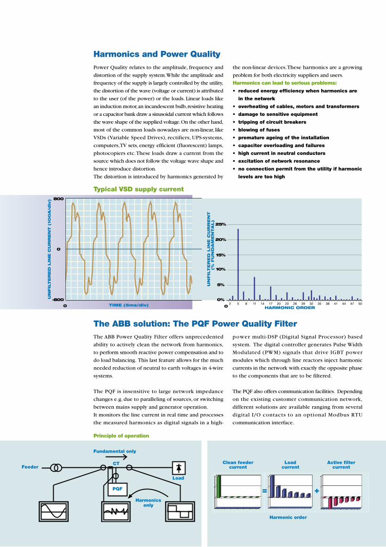
Principle of operation
Load
Harmonics and Power Quality
The ABB solution: The PQF Power Quality Filter
Fundamental only
UN
FIL
TE
RE
DLIN
EC
UR
RE
NT
(10
0A
/div
) 800
-800
0
0 TIME (5ms/div)
Harmonicsonly
Feeder
Typical VSD supply current
2 5 8 11 14 17 20 23 26 29 32 35 38 41 44 47 50
UN
FIL
TE
RE
DLIN
EC
UR
RE
NT
(%FU
ND
AM
EN
TA
L)
0%
5%
10%
15%
20%
25%
0 HARMONIC ORDER
Clean feedercurrent
Harmonic order
Loadcurrent
= +
Active filtercurrent
PQF
CT
3ABB
• Has programmable task priorities• Two sets of compensation parameters for
different load type compensation• Is not overloadable• Programmable stand-by and re-start
functions• Fault and event logging with real time stamp• Direct connection up to 690V (CE/C-Tick)
and 600V (cUL)• Top or bottom cable entry (bottom cable
entry only for PQFS)• Easy commissioning – auto-detection of
CT polarity and installed phase• Does not require detailed network analysis• Does not require special CTs• Is easy to extend on site• Comes factory tested• Optical fiber isolation between power and
control stages• Advanced programmable digital I/O interface• Modbus RTU communication compatible• 3 phase 3/4 wire connectivity (PQFS)• Easy wall mounting design (PQFS)• Backlit user interface (PQF-Manager)
• Allows installations to run more efficiently• Filters up to 20 harmonics simultaneously
(15 for PQFK and PQFS in 4-wire mode)• Filters up to the 50th harmonic• Filters zero phase sequence harmonics
(3rd, 9th, ...) in the neutral (PQFK and PQFS)• Harmonic attenuation factor better than
97%• Fulfillment of international guidelines like
G5/4, IEEE 519, etc• Operates with closed loop control for best
accuracy• Has a programmable filtering strategy and
free choice of harmonics selection• Auto-adaptation to network impedance
changes• May filter without generation of reactive
power/load balancing• May generate reactive power and control
power factor• May balance the load current across the
phases and between phases and neutral(PQFK and PQFS)
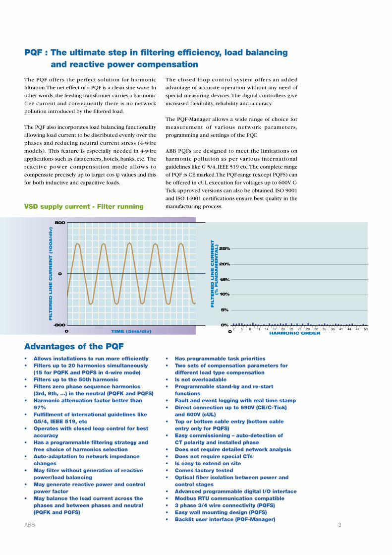
The PQF offers the perfect solution for harmonic
filtration.The net effect of a PQF is a clean sine wave. In
other words, the feeding transformer carries a harmonic
free current and consequently there is no network
pollution introduced by the filtered load.
The PQF also incorporates load balancing functionality
allowing load current to be distributed evenly over the
phases and reducing neutral current stress (4-wire
models). This feature is especially needed in 4-wire
applications such as datacenters, hotels, banks, etc. The
react ive power compensat ion mode a l lows to
compensate precisely up to target cos j values and this
for both inductive and capacitive loads.
The closed loop control system offers an added
advantage of accurate operation without any need of
special measuring devices.The digital controllers give
increased flexibility, reliability and accuracy.
The PQF-Manager allows a wide range of choice for
measurement of var ious network parameters ,
programming and settings of the PQF.
ABB PQFs are designed to meet the limitations on
harmonic pollution as per var ious internationa l
guidelines like G 5/4, IEEE 519 etc.The complete range
of PQF is CE marked.The PQF-range (except PQFS) can
be offered in cUL execution for voltages up to 600V. C-
Tick approved versions can also be obtained. ISO 9001
and ISO 14001 certifications ensure best quality in the
manufacturing process.
Advantages of the PQF
PQF : The ultimate step in filtering efficiency, load balancingand reactive power compensation
FIL
TE
RE
DLIN
EC
UR
RE
NT
(10
0A
/div
)
800
-800
0
0 TIME (5ms/div)
VSD supply current - Filter running
2 5 8 11 14 17 20 23 26 29 32 35 38 41 44 47 50
FIL
TE
RE
DLIN
EC
UR
RE
NT
(%FU
ND
AM
EN
TA
L)
0%
5%
10%
15%
20%
25%
0 HARMONIC ORDER
4 ABB
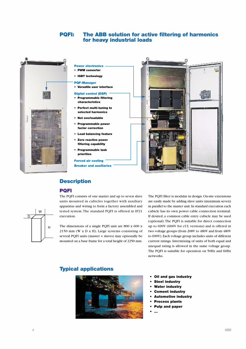
PQFI: The ABB solution for active filtering of harmonicsfor heavy industrial loads
Description
Typical applications
PQFIThe PQFI consists of one master and up to seven slave
units mounted in cubicles together with auxiliary
apparatus and wiring to form a factory assembled and
tested system.The standard PQFI is offered in IP21
execution.
The dimensions of a single PQFI unit are 800 x 600 x
2150 mm (W x D x H). Large systems consisting of
several PQFI units (master + slaves) may optionally be
mounted on a base frame for a total height of 2250 mm.
The PQFI filter is modular in design. On-site extensions
are easily made by adding slave units (maximum seven)
in parallel to the master unit. In standard execution each
cubicle has its own power cable connection terminal.
If desired, a common cable entry cubicle may be used
(optional).The PQFI is suitable for direct connection
up to 690V (600V for cUL versions) and is offered in
two voltage groups (from 208V to 480V and from 480V
to 690V). Each voltage group includes units of different
current ratings. Intermixing of units of both equal and
unequal rating is allowed in the same voltage group.
The PQFI is suitable for operation on 50Hz and 60Hz
networks.
W
H
D
• Oil and gas industry• Steel industry• Water industry• Cement industry• Automotive industry• Process plants• Pulp and paper• …
Power electronics• PWM converter
• IGBT technology
PQF-Manager• Versatile user interface
Digital control (DSP)• Programmable filtering
characteristics
• Perfect multi-tuning toselected harmonics
• Not overloadable
• Programmable powerfactor correction
• Load balancing feature
• Zero reactive powerfiltering capability
• Programmable taskpriorities
Forced air cooling
Breaker and auxiliaries

5ABB
PQFI technical specificationsActive filter for three-phase networks with or without neutral for filtering of non zero phase sequence harmonics and reactive power compensation
including load balancing.
Connection diagram
CT1 CT2 CT3 L1 L2 L3
L1
L3L2
x/5Ax/5A
x/5A
P.E.
SUPPLY LOAD(S)
PQFI
Typical result of PQFI filtering application
Modbus communicationElectrical digital I/O interface
0THD H05 H10 H15 H20 H25
5
10
15
20
25
30
35
0THD H05 H10 H15 H20 H25
5
10
15
20
25
30
35
Harmonic current without PQF Harmonic current with PQF
%FU
ND
HARMONIC ORDER
%FU
ND
HARMONIC ORDER
Filter line current per unit (RMS)(50 or 60 Hz)
CT requirement
Modularity
Physical mountingTolerance
Harmonics to filter
Degree of filtering
Harmonic attenuation factor(IH (source)/IH (load))Reactive power
Load balancingCommunication
Digital I/O
Programming
Response time
208V≤U≤480V 480V<U≤690V*250 A 180 A*450 A 320 A*
3 CTs required (class 1.0 or better).5 Amps secondary rating.Filter burden: 5 VA.Up to 8 units (intermixing of units of bothequal and unequal rating is allowed inthe same voltage group).One unit per panel.+/- 10% in voltage.+/- 5% in frequency.20 individual harmonics selectable from 2nd
to 50th order.Individually programmable per harmonic inabsolute terms.Better than 97% at rated load.
Target displacement power factor programmablefrom 0.6 (inductive) to 0.6 (capacitive).Programmable load balancing between phases.Using Modbus RTU interface (optional).Through RS-232 port with optional dedicatedsoftware (PQF-Link).6 digital outputs (free of potential).2 digital inputs (free of potential).1 NO/NC alarm contact (free of potential).Using PQF-Manager.Using PQF-Link software (optional) and PC(not provided).< 0.5 ms instantaneous.40 ms (10-90% filtering).
Active powerProtection degree
Cubicle dimensionWeight (unpacked)
Color
Installation
Environment
AmbienttemperatureHumidityMain options
< 3% of the device power typically.IP21 (IP20 open door).Optionally, IP41 protection degree can be provided.800 x 600 x 2150 mm (W x D x H).Appr. 620 kg (450A/320A)or 525 kg (250A/180A) per unit.RAL 7035 (light gray).Other colors on request.Floor fixation, lifting lugs provided, cableentry from bottom.Indoor installation in clean environment upto 1000 m altitude (higher altitudes withsuitable derating).-10°C to +40°C (Up to 50°C with suitablederating).Maximum 95% RH; non-condensing.PQF-Link software.Common cable entry cubicle with top/bottomcable entry.IP41 protection degree (10% derating applies).Base frame (100 mm).Modbus kit (RS-485 based).MCB position status lamps.Surge arresters.Space heaters.Temperature probes.
* If the system voltage is higher than 600V the current rating of PQFI units may be derated automaticallydepending on the load conditions for ambient temperatures higher than 30°C. cUL versions are limited to 600V.
The data here presented is an extract of the complete product specification. Please refer to the document“PQFI-PQFM-PQFK-PQFS detailed technical specifications” for more technical information.

6 ABB
PQFM: The ABB solution for active filtering of harmonicsfor industrial loads of lower capacity
Description
Typical applications
PQFMThe PQFM consists of one master and up to seven slave
units mounted in cubicles together with auxiliary
apparatus and wiring to form a factory assembled and
tested system.The standard PQFM is offered in IP21
execution and plate execution (IP00).
The dimensions of a single PQFM unit are 600 x 600
x 2150 mm (W x D x H).The dimensions of the IP00
execution are 498 x 504 x 1697 mm (W x D x H).
The PQFM filter is modular in design.On-site extensions
are easily made by adding slave units (maximum seven)
in parallel to the master unit. In standard execution
each cubicle has its own power cable connection
terminal. If desired, a common cable entry cubicle may
be used (optional).The PQFM is offered in the range
from 208V to 480V (600V for cUL versions). This range
includes units of different current ratings. Intermixing
of units of both equal and unequal rating is allowed
(maximum one unit rating difference between the
largest and the smallest unit rating in a filter system).
The PQFM is suitable for operation on 50Hz and 60Hz
networks.
W
H
D
• Water industry• Steel industry• Oil and gas industry• Cement industry• Automotive industry• Process plants• Pulp and paper• …
PQF-Manager• Versatile user interface
Digital control (DSP)• Programmable filtering
characteristics
• Perfect multi-tuning toselected harmonics
• Not overloadable
• Programmable powerfactor correction
• Load balancing feature
• Zero reactive powerfiltering capability
• Programmable taskpriorities
Power electronics• PWM converter
• IGBT technologs
Forced air cooling
Top or bottom cable entry
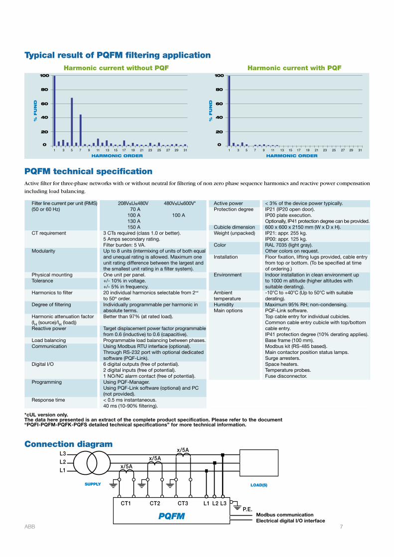
Typical result of PQFM filtering application
Connection diagram
CT1 CT2 CT3 L1 L2 L3
L1
L3L2
x/5Ax/5A
x/5A
P.E.
SUPPLY LOAD(S)
PQFM Modbus communicationElectrical digital I/O interface
PQFM technical specificationActive filter for three-phase networks with or without neutral for filtering of non zero phase sequence harmonics and reactive power compensation
including load balancing.
1 3 5 7 9 11 13 15 17 19 21 23 25 27 29 31
%FU
ND
HARMONIC ORDER
0
40
20
60
80
100
1 3 5 7 9 11 13 15 17 19 21 23 25 27 29 31
%FU
ND
HARMONIC ORDER
0
40
20
60
80
100
Harmonic current without PQF Harmonic current with PQF
Filter line current per unit (RMS)(50 or 60 Hz)
CT requirement
Modularity
Physical mountingTolerance
Harmonics to filter
Degree of filtering
Harmonic attenuation factor(IH (source)/IH (load))Reactive power
Load balancingCommunication
Digital I/O
Programming
Response time
Active powerProtection degree
Cubicle dimensionWeight (unpacked)
Color
Installation
Environment
AmbienttemperatureHumidityMain options
208V≤U≤480V 480V≤U≤600V*70 A
100 A 100 A130 A150 A
3 CTs required (class 1.0 or better).5 Amps secondary rating.Filter burden: 5 VA.Up to 8 units (intermixing of units of both equaland unequal rating is allowed. Maximum oneunit rating difference between the largest andthe smallest unit rating in a filter system).One unit per panel.+/- 10% in voltage.+/- 5% in frequency.20 individual harmonics selectable from 2nd
to 50th order.Individually programmable per harmonic inabsolute terms.Better than 97% (at rated load).
Target displacement power factor programmablefrom 0.6 (inductive) to 0.6 (capacitive).Programmable load balancing between phases.Using Modbus RTU interface (optional).Through RS-232 port with optional dedicatedsoftware (PQF-Link).6 digital outputs (free of potential).2 digital inputs (free of potential).1 NO/NC alarm contact (free of potential).Using PQF-Manager.Using PQF-Link software (optional) and PC(not provided).< 0.5 ms instantaneous.40 ms (10-90% filtering).
< 3% of the device power typically.IP21 (IP20 open door).IP00 plate execution.Optionally, IP41 protection degree can be provided.600 x 600 x 2150 mm (W x D x H).IP21: appr. 255 kg.IP00: appr. 125 kg.RAL 7035 (light gray).Other colors on request.Floor fixation, lifting lugs provided, cable entryfrom top or bottom. (To be specified at timeof ordering.)Indoor installation in clean environment upto 1000 m altitude (higher altitudes withsuitable derating).-10°C to +40°C (Up to 50°C with suitablederating).Maximum 95% RH; non-condensing.PQF-Link software.Top cable entry for individual cubicles.Common cable entry cubicle with top/bottomcable entry.IP41 protection degree (10% derating applies).Base frame (100 mm).Modbus kit (RS-485 based).Main contactor position status lamps.Surge arresters.Space heaters.Temperature probes.Fuse disconnector.
*cUL version only.The data here presented is an extract of the complete product specification. Please refer to the document“PQFI-PQFM-PQFK-PQFS detailed technical specifications” for more technical information.
7ABB
8 ABB
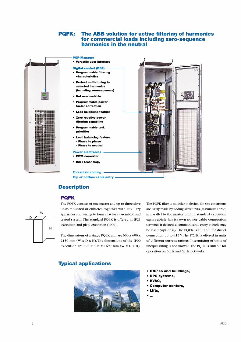
PQFK: The ABB solution for active filtering of harmonicsfor commercial loads including zero-sequenceharmonics in the neutral
Description
Typical applications
PQFKThe PQFK consists of one master and up to three slave
units mounted in cubicles together with auxiliary
apparatus and wiring to form a factory assembled and
tested system.The standard PQFK is offered in IP21
execution and plate execution (IP00).
The dimensions of a single PQFK unit are 600 x 600 x
2150 mm (W x D x H).The dimensions of the IP00
execution are 498 x 403 x 1697 mm (W x D x H).
The PQFK filter is modular in design.On-site extensions
are easily made by adding slave units (maximum three)
in parallel to the master unit. In standard execution
each cubicle has its own power cable connection
terminal. If desired, a common cable entry cubicle may
be used (optional).The PQFK is suitable for direct
connection up to 415 V.The PQFK is offered in units
of different current ratings. Intermixing of units of
unequal rating is not allowed.The PQFK is suitable for
operation on 50Hz and 60Hz networks.
W
H
D
• Offices and buildings,• UPS systems,• HVAC,• Computer centers,• Lifts,• ...
PQF-Manager• Versatile user interface
Digital control (DSP)• Programmable filtering
characteristics
• Perfect multi-tuning toselected harmonics(including zero-sequence)
• Not overloadable
• Programmable powerfactor correction
• Load balancing feature
• Zero reactive powerfiltering capability
• Programmable taskpriorities
• Load balancing feature- Phase to phase- Phase to neutral
Power electronics• PWM converter
• IGBT technology
Forced air cooling
Top or bottom cable entry

9ABB
Typical result of PQFK filtering application
Connection diagram
SUPPLYLOAD(S)
PQFK Modbus communicationElectrical digital I/O interface
PQFK technical specificationActive filter for three-phase four-wire systems for filtering of harmonics, including zero phase sequence current in the neutral, reactive power
compensation and load balancing between phases as well as between phases and neutral.
1 3 5 7 9 11 13 15 17 19 21 23 25 27 29 31
%FU
ND
HARMONIC ORDER
0
40
20
60
80
100
1 3 5 7 9 11 13 15 17 19 21 23 25 27 29 31
%FU
ND
HARMONIC ORDER
0
40
20
60
80
100
Neutral harmonic current without PQF Neutral harmonic current with PQF
Note: the PQFK filters also harmonics between lines apart from the neutral conductor.
Filter line current per unit (RMS)(50 or 60 Hz)
Neutral current
CT requirement
ModularityPhysical mountingTolerance
Harmonics to filter
Degree of filtering
Harmonic attenuation factor(IH (source)/IH (load))Reactive power
Load balancing
Communication
Digital I/O
Programming
Response time
208V≤U≤415V70 A
100 A3 times the line RMS current mentionedabove.3 CTs required (class 1.0 or better).5 Amps secondary rating.Filter burden: 5 VA.Up to 4 units of equal rating.One unit per panel.+/- 10% in voltage.+/- 5% in frequency.15 individual harmonics selectable from 2nd
to 50th order.Individually programmable per harmonic inabsolute terms.Better than 97% (at rated load).
Target displacement power factor programmablefrom 0.6 (inductive) to 0.6 (capacitive).Programmable load balancing between phasesand between phases and neutral.Using Modbus RTU interface (optional).Through RS-232 port with optional dedicatedsoftware (PQF-Link).6 digital outputs (free of potential).2 digital inputs (free of potential).1 NO/NC alarm contact (free of potential).Using PQF-Manager.Using PQF-Link software (optional) and PC(not provided).< 0.5 ms instantaneous.40 ms (10-90% filtering).
Active powerProtection degree
Cubicle dimensionWeight (unpacked)
Color
Installation
Environment
AmbienttemperatureHumidityMain options
< 3% of the device power typically.IP21 (IP20 open door).IP00 plate execution.Optionally, IP41 protection degree can be provided.600 x 600 x 2150 mm (W x D x H).IP21: appr. 250 kg.IP00: appr. 175 kg.RAL 7035 (light gray).Other colors on request.Floor fixation, lifting lugs provided, cable entryfrom top or bottom. (To be specified at timeof ordering.)Indoor installation in clean environment upto 1000 m altitude (higher altitudes withsuitable derating).-10°C to + 40°C (Up to 50°C with suitablederating).Maximum 95% RH; non-condensing.PQF-Link software.Top cable entry for individual cubiclesCommon cable entry cubicle with top/bottomcable entry.IP41 protection degree (10% derating applies).Base frame (100 mm).Modbus kit (RS-485 based).Main contactor position status lamps.Space heaters.Temperature probes.Fuse disconnector.
N
The data here presented is an extract of the complete product specification. Please refer to the document“PQFI-PQFM-PQFK-PQFS detailed technical specifications” for more technical information.

10 ABB
PQFS: The ABB solution for active filtering of harmonicsfor commercial, residential and light industrial loadsfor installations with or without neutral
Description
Typical applications
PQFSThe PQFS is suitable for connection to electrical networks
with and without neutral. Its wall-mount,compact design
allows it to be installed at any location where only limited
space is available.The PQFS is offered in IP30 execution.
The dimensions of a single PQFS unit are 585 x 310 x
700 mm (W x D x H).
The PQFS is modular in design and consists of one
master and up to three slave units. On-site extensions
are easily made by adding the slave units side by side
in parallel to the master unit. PQFS units are available
in the current range from 30 A to 100 A. Intermixing
of units of unequal rating is not allowed.
The PQFS is suitable for direct connection to network
voltages in the range 208 V - 240 V and 380 V - 415 V. It
is suitable for operation on 50 Hz and 60 Hz networks.
W
H
D
• Offices and buildings,• UPS systems,• Residential buildings,• Computer centers,• Light industrial loads,• ...
Compact wall mounted design
3 and 4 wire functionality
PQF-Manager• Versatile user interface
Digital control (DSP)• Programmable filtering characteristics
• Perfect multi-tuning to selectedharmonics(including zero-sequence)
• Not overloadable
• Programmable power factor correction
• Load balancing feature
- Phase to phase
- Phase to neutral
• Zero reactive power filtering capability
• Programmable task priorities
Power electronics• PWM converter
• IGBT technology
Bottom cable entry

11ABB
Typical result of PQFS filtering application
Connection diagram
SUPPLYLOAD(S)
PQFS Modbus communicationElectrical digital I/O interface
PQFS technical specificationActive filter for three-phase three-wire and four-wire systems for filtering of harmonics,including zero phase sequence current in the neutral,reactive power
compensation and load balancing between phases as well as between phases and neutral.
1 3 5 7 9 11 13 15 17 19 21 23 25 27 29 31
%FU
ND
HARMONIC ORDER
0
40
20
60
80
100
1 3 5 7 9 11 13 15 17 19 21 23 25 27 29 31
%FU
ND
HARMONIC ORDER
0
40
20
60
80
100
Neutral harmonic current without PQF Neutral harmonic current with PQF
Note: the PQFS filters also harmonics between lines apart from the neutral conductor when connected.
Filter line current per unit (RMS)(50 or 60 Hz)
Neutral current
CT requirement
ModularityPhysical mountingTolerance
Harmonics to filter
Degree of filtering
Harmonic attenuation factor(IH (source)/IH (load))Reactive power
Load balancing
208V≤U≤240V 380V≤U≤415V30 A 30 A45 A 45 A60 A 60 A70 A 70 A80 A 80 A90 A 90 A
100 A 100 A3 times the line RMS current mentionedabove limited to 270 Arms.3 CTs required (class 1.0 or better).5 Amps secondary rating.Filter burden: 5 VA.Up to 4 units of equal rating.Wall mount type enclosure.+/- 10% in voltage.+/- 5% in frequency.3-wire connection: 20 individual harmonicsselectable from 2nd to 50th order.4-wire connection: 15 individual harmonicsselectable from 2nd to 50th order.Individually programmable per harmonic inabsolute terms.Better than 97% (at rated load).
Target displacement power factor programmablefrom 0.6 (inductive) to 0.6 (capacitive).Programmable load balancing betweenphases and between phases and neutral.
Communication
Digital I/O
Programming
Response time
Active powerProtection degreeEnclosure dimensionWeight (unpacked)Color
InstallationEnvironment
AmbienttemperatureHumidityOptions
Using Modbus RTU interface (optional).Through RS-232 port with optional dedicatedsoftware (PQF-Link).6 digital outputs (free of potential).2 digital inputs (free of potential).1 NO/NC alarm contact (free of potential).Using PQF-Manager.Using PQF-Link software (optional) and PC(not provided).< 0.5 ms instantaneous.40 ms (10-90% filtering).< 3% of the device power typically.IP30.585 x 310 x 700 mm (W x D x H).120 kg.RAL 7035 (light gray)Other colors on request.Wall mounting, cable entry from bottom.Indoor installation in clean environment upto 1000 m altitude (higher altitudes withsuitable derating).-10°C to + 40°C (Up to 50°C with suitablederating).Maximum 95% RH; non-condensing.PQF-Link software.Cable connection box.Modbus kit (RS-485 based).Temperature probes.PQF-Manager extension kit.
N*
* not compulsory
The data here presented is an extract of the complete product specification. Please refer to the document“PQFI-PQFM-PQFK-PQFS detailed technical specifications” for more technical information.
IL1 = 34A
IL2 = 17A
IL3 = 19A
IN = 44A
IL1 = 20A
IL2 = 20A
IL3 = 20A
IN = 4A

12 ABB
DISPLAYThe PQF-Manager backlit large display provides the
following main functions :
• Starting, stopping and resetting the filter
• Measurement, analysis, logging and printing
of characteristic parameters
• Setting up the filter
• Monitoring the filter load and fault logging
• Providing filter identification information
KEYPADThere are 5 keys which include Up, Down, OK,
Escape and Help functions. Using these keys the
user easily navigates through the various menus and
controls the PQF.
MENUSFour main menus exist:
• Measurements
• Settings
• PQF monitoring
• About PQF
MeasurementsThe PQF-Manager measures all parameters like
• Line voltages* (RMS and fundamental)
• Line currents* (RMS and fundamental)
• Filter currents* (RMS)
• Frequency
• Voltage distortion
• Current distortion
• Line voltage imbalance
• Active power (kW)
• Reactive power (kvar)
• Apparent power (kVA)
• Displacement Power Factor (DPF)
• Power Factor (PF)
• DC voltage indication
• Max. IGBT temperature
Furthermore the PQF-Manager allows monitoring of
temperatures using two optional temperature probes.
The PQF-Manager offers an excellent min/max logging
function. For most of the measured parameters, it can
display the defined threshold value and the duration
during which the threshold value is exceeded. The
maximum value encountered is also shown.
The PQF-ManagerThe PQF-Manager is the Graphical User Interface
provided with all the PQF types as a standard accessory.
It offers direct control, programming, monitoring
capabilities without a PC,communication facilities and
detailed fault and event logging with real time stamp.
The PQF-Manager (144 x 144 mm), fitted in the front
panel of the PQF with its large backlit LCD screen
display (64 x 132 pixel) makes operating the filter very
convenient.
* Harmonic charts, harmonic tables and waveforms can be displayed.

13ABB
SettingsThe Settings menu has various sub-menus allowing a wide
range of possibilities for the user to set up the PQF
parameters, target values, task priorities and installation
settings like CT ratio, derating factor, unit current rating,
network parameters like voltage and frequency,…
The commissioning settings are used to set the basic
parameters which include the network characteristics,
unit rating, derating, real time clock settings, print and
communication settings.There is also an automatic CT
detection program which finds wrong CT connections
and proposes the CT ratio.
The settings may be protected by a password.A hardware
lock is also available to avoid any unauthorized or
accidental change of PQF-Manager settings.
PQF MonitoringThis menu allows an overview of the PQF operation
including the fault and event log. The PQF loading
indicates the percentage of filter capacity used.The
faults and events logged have a real time stamp.
About PQFThis menu shows the serial number and software
version of the PQF.
threshold
%
total duration = t1 + t2 + t3
t1 t2 t3
maximum recorded
time
Powerful featuresFully graphics backlit displayWith its large dimensions and the clear positioning of
information,prompts and icons, the backlit PQF-Manager
offers a high level of readability and an unprecedented
level of viewing comfort.
Menu navigationA simple and user friendly organization of menus and
items makes the navigation easy and intuitive.
CommunicationThe PQF -Manager is provided with Modbus RTU
communication features.Through a Modbus RS-485
converter (optional), the PQF can be linked to a
supervision system of the customer.All parameters,
settings and measurements are accessible remotely.
Help buttonThe Help button gives instant access to a comprehensive
description of most of the features and functionality of
the PQF.
Easy commissioningWith automatic detection and correction of CT reversal
commissioning is made easy.
Main/auxiliary parametersThe PQF-Manager allows for two sets of parameters for
harmonic filtering and reactive power compensation
and load balancing.
Programmable electrical digital I/OThe PQF-Manager has two opto-isolated digital inputs,
six programmable digital outputs and one potential free
alarm relay with a NO and a NC contact.
Min/Max loggingThe PQF-Manager can record the total duration any
specific network parameter has exceeded the set value
as well as record the extreme values measured.
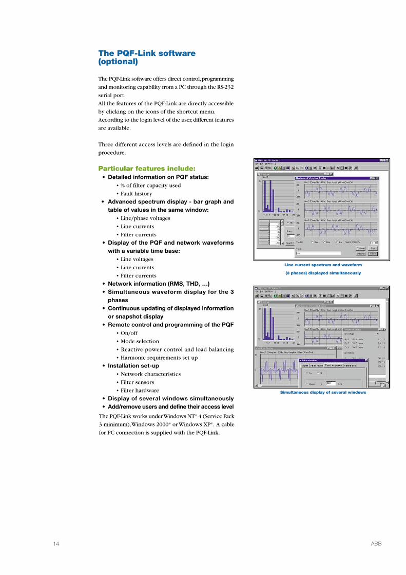
Line current spectrum and waveform
(3 phases) displayed simultaneously
Simultaneous display of several windows
The PQF-Link software(optional)
The PQF-Link software offers direct control,programming
and monitoring capability from a PC through the RS-232
serial port.
All the features of the PQF-Link are directly accessible
by clicking on the icons of the shortcut menu.
According to the login level of the user,different features
are available.
Three different access levels are defined in the login
procedure.
Particular features include:• Detailed information on PQF status:
• % of filter capacity used
• Fault history
• Advanced spectrum display - bar graph andtable of values in the same window:
• Line/phase voltages
• Line currents
• Filter currents
• Display of the PQF and network waveformswith a variable time base:
• Line voltages
• Line currents
• Filter currents
• Network information (RMS, THD, …)• Simultaneous waveform display for the 3
phases• Continuous updating of displayed information
or snapshot display• Remote control and programming of the PQF
• On/off
• Mode selection
• Reactive power control and load balancing
• Harmonic requirements set up
• Installation set-up• Network characteristics
• Filter sensors
• Filter hardware
• Display of several windows simultaneously• Add/remove users and define their access level
The PQF-Link works underWindows NT® 4 (Service Pack
3 minimum),Windows 2000® or Windows XP®. A cable
for PC connection is supplied with the PQF-Link.
14 ABB
PQFI From 480V to 690V (voltage group V2) PQFM(2)
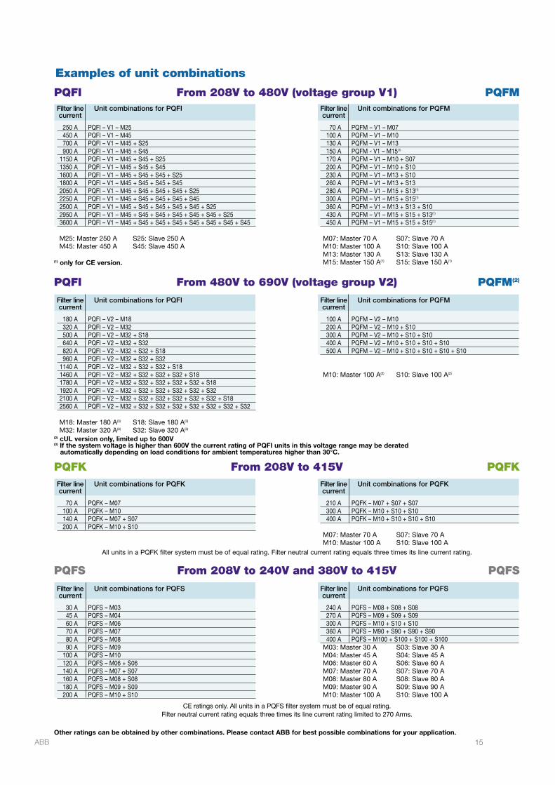
All units in a PQFK filter system must be of equal rating. Filter neutral current rating equals three times its line current rating.
CE ratings only. All units in a PQFS filter system must be of equal rating.Filter neutral current rating equals three times its line current rating limited to 270 Arms.
PQFI From 208V to 480V (voltage group V1) PQFM
PQFK From 208V to 415V PQFK
PQFS From 208V to 240V and 380V to 415V PQFS
(2) cUL version only, limited up to 600V(3) If the system voltage is higher than 600V the current rating of PQFI units in this voltage range may be derated
automatically depending on load conditions for ambient temperatures higher than 30°C.
Other ratings can be obtained by other combinations. Please contact ABB for best possible combinations for your application.
Examples of unit combinations
15ABB
Filter line Unit combinations for PQFIcurrent
250 A PQFI – V1 – M25450 A PQFI – V1 – M45700 A PQFI – V1 – M45 + S25900 A PQFI – V1 – M45 + S45
1150 A PQFI – V1 – M45 + S45 + S251350 A PQFI – V1 – M45 + S45 + S451600 A PQFI – V1 – M45 + S45 + S45 + S251800 A PQFI – V1 – M45 + S45 + S45 + S452050 A PQFI – V1 – M45 + S45 + S45 + S45 + S252250 A PQFI – V1 – M45 + S45 + S45 + S45 + S452500 A PQFI – V1 – M45 + S45 + S45 + S45 + S45 + S252950 A PQFI – V1 – M45 + S45 + S45 + S45 + S45 + S45 + S253600 A PQFI – V1 – M45 + S45 + S45 + S45 + S45 + S45 + S45 + S45
M25: Master 250 A S25: Slave 250 AM45: Master 450 A S45: Slave 450 A
Filter line Unit combinations for PQFIcurrent
180 A PQFI – V2 – M18320 A PQFI – V2 – M32500 A PQFI – V2 – M32 + S18640 A PQFI – V2 – M32 + S32820 A PQFI – V2 – M32 + S32 + S18960 A PQFI – V2 – M32 + S32 + S32
1140 A PQFI – V2 – M32 + S32 + S32 + S181460 A PQFI – V2 – M32 + S32 + S32 + S32 + S181780 A PQFI – V2 – M32 + S32 + S32 + S32 + S32 + S181920 A PQFI – V2 – M32 + S32 + S32 + S32 + S32 + S322100 A PQFI – V2 – M32 + S32 + S32 + S32 + S32 + S32 + S182560 A PQFI – V2 – M32 + S32 + S32 + S32 + S32 + S32 + S32 + S32
M18: Master 180 A(3) S18: Slave 180 A(3)
M32: Master 320 A(3) S32: Slave 320 A(3)
Filter line Unit combinations for PQFKcurrent
70 A PQFK – M07100 A PQFK – M10140 A PQFK – M07 + S07200 A PQFK – M10 + S10
Filter line Unit combinations for PQFScurrent
30 A PQFS – M0345 A PQFS – M0460 A PQFS – M0670 A PQFS – M0780 A PQFS – M0890 A PQFS – M09
100 A PQFS – M10120 A PQFS – M06 + S06140 A PQFS – M07 + S07160 A PQFS – M08 + S08180 A PQFS – M09 + S09200 A PQFS – M10 + S10
Filter line Unit combinations for PQFMcurrent
70 A PQFM – V1 – M07100 A PQFM – V1 – M10130 A PQFM – V1 – M13150 A PQFM - V1 – M15(1)
170 A PQFM – V1 – M10 + S07200 A PQFM – V1 – M10 + S10230 A PQFM – V1 – M13 + S10260 A PQFM – V1 – M13 + S13280 A PQFM – V1 – M15 + S13(1)
300 A PQFM – V1 – M15 + S15(1)
360 A PQFM – V1 – M13 + S13 + S10430 A PQFM – V1 – M15 + S15 + S13(1)
450 A PQFM – V1 – M15 + S15 + S15(1)
M07: Master 70 A S07: Slave 70 AM10: Master 100 A S10: Slave 100 AM13: Master 130 A S13: Slave 130 AM15: Master 150 A(1) S15: Slave 150 A(1)
Filter line Unit combinations for PQFMcurrent
100 A PQFM – V2 – M10200 A PQFM – V2 – M10 + S10300 A PQFM – V2 – M10 + S10 + S10400 A PQFM – V2 – M10 + S10 + S10 + S10500 A PQFM – V2 – M10 + S10 + S10 + S10 + S10
M10: Master 100 A(2) S10: Slave 100 A(2)
Filter line Unit combinations for PQFKcurrent
210 A PQFK – M07 + S07 + S07300 A PQFK – M10 + S10 + S10400 A PQFK – M10 + S10 + S10 + S10
M07: Master 70 A S07: Slave 70 AM10: Master 100 A S10: Slave 100 A
Filter line Unit combinations for PQFScurrent
240 A PQFS – M08 + S08 + S08270 A PQFS – M09 + S09 + S09300 A PQFS – M10 + S10 + S10360 A PQFS – M90 + S90 + S90 + S90400 A PQFS – M100 + S100 + S100 + S100
M03: Master 30 A S03: Slave 30 AM04: Master 45 A S04: Slave 45 AM06: Master 60 A S06: Slave 60 AM07: Master 70 A S07: Slave 70 AM08: Master 80 A S08: Slave 80 AM09: Master 90 A S09: Slave 90 AM10: Master 100 A S10: Slave 100 A
(1) only for CE version.
2G
CS
30
40
17
A0
07
0A
pril
20
08
©C
opyr
ight
2008
AB
B.A
llrig
hts
rese
rved
While all care has been taken to ensure that the information contained in this publication is correct, no responsibility
can be accepted for any inaccuracy. We reserve the right to alter or modify the information contained herein at
any time in the light of technical or other developments. Technical specifications are valid under normal operating
conditions only. We do not accept any responsibility for any misuse of the product and cannot be held liable for
indirect or consequential damages.
www.abb.com/lowvoltage