p-750 operation & safety instruction manual
TRANSCRIPT

P-750Operation & Safety Instruction Manual
WARNINGUnsafe use of this equipment could result in serious injury or death. This manual con-tains important instructions for the safe operation and recommended maintenance of your P-750. All operators must carefully read and understand this manual before start-ing the machine. Keep this manual available both as a reminder for your experienced operator and as a training aid for your new staff. Replacement manuals are available
by calling American Augers.
P-750 Operators ManualForeword
Introduction
Foreword
INTRODUCTION
Since 1970, American Augers has been a devoted manufacturer of trenchless technology equipment; customers worldwide will recognize the P-750 as a premier piece of equipment that is a vital accessory to our directional drilling equipment. American Augers always provides its equipment with worldwide technical support, parts and service. American Augers encourages customers to contact the factory with any opera-tional or assistance needs.
Every effort has been made to adequately cover the operation of the P-750 in this
manual.Specifications are subject to change without
notice or obligation. American Augers will con-tinue to update its product manuals with current operational information, but some units maybe retrofitted independently by the customer or by the manufacturer per a customer request at the factory, or while in service, and the information herein may not reflect those changes.
The materials may not be reproduced in whole or in part without the express written per-mission of American Augers Inc.
Page 2 Refer to the Safety Awareness Program in this manual before attempting to operate this machine
Original InstructionsManual Part Number 75MP10000Released May 2012 Revision 01
Wiggle Steer, es!lok and Quiet-Pak are registered trademarks of American Augers, Inc.All other trademarks are the property of their respective owners.

P-750 Operators Manual Foreword
Machine Serial Number Locations
Location of Machine Serial Number Plate
Machine Serial Number
Used on machines made prior to 2010
Used on machines made after 2009
Page 3Refer to the Safety Awareness Program in this manual before attempting to operate this machine
Location of Engine Serial Number Plate
Engine Serial Number

P-750 Operators ManualForeword
Safety Awareness Program
Understanding Operation Safety
This manual is part of the safety system of the equipment.Use it when training personnel who will oper-ate the machine or work on the jobsite. Ensure that a copy is always available with the machine and that the operators have read it and have access to it. Carefully follow the instructions, advice and procedures it con-tains.
Mud pumps have a number of hazards unique to their operation. Safety alert decals are provided on American Augers’ equipment to alert the operator to hazards of the machines. The “Safety Alerts” section beginning on page 25 shows these hazard alert signs.
Signal Words
Signal words are used to identify safety information within the text of this manual. They are reserved for personal injury hazards.
is used for a hazard with a high level of risk which, if not avoided, will result in death or serious injury.
is used for a hazard with a medium level of risk which, if not avoided, could result in death or serious injury.
is used for a hazard with a low level of risk which, if not avoided, could result in a minor or moderate injury.
NOTICE: Hazard alert signs are placed on the machine to inform your operator and other personnel of potential hazards that exist while these machines are in operation. These decals should be kept clean and legible. Replacement decals are available from American Augers.
Page 4 Refer to the Safety Awareness Program in this manual before attempting to operate this machine

P-750 Operators Manual Foreword
Revision Record
Revision to ManualRevision Number Description of Change Date
00 Initial release; Serial Numbers P750010308 through P750020308. 4/28/200801 Updated content, format, CE compliance information, Declaration of 5/21/2012
Conformity letter; Machines manufactured under top level 75MP1015from serial number P750050311; Tier 3 and Tier 4i engines
Page 5Refer to the Safety Awareness Program in this manual before attempting to operate this machine
P-750 Operators Manual
Page
Foreword
Re
Revision Record
Revision to Manual, Continuedvision Number Description of Change Date
6 Refer to the Safety Awareness Program in this manual before attempting to operate this machine
P-750 Operators Manual Foreword
To The Owner
To The Owner
Thank you for your purchase of the American Augers P-750. This is an authorized accessory for use with our directional drills.
This manual contains important information that will help you and your crew set up and safely operate the P-750. DO NOT operate or permit anyone to operate or service this machine until you have read this Manual. Use only trained operators who have demonstrated the ability to operate and service this machine correctly and safely.
DO NOT use this machine for any application or purpose other than those described in this Manual. Consult the American Augers factory for changes, additions, or modifications that may be required for this machine to comply with various safety requirements. Unauthorized modifications could cause serious injury or death. Anyone making such unauthorized modifications is responsible for the consequences.
Make sure this Manual is complete and in good condition. Contact the American Augers factory to obtain additional manuals and for further information about or assistance with your machine. Your American Augers factory has approved service parts and technicians with special training that know the best methods of repair and maintenance for your machine.
Page 7Refer to the Safety Awareness Program in this manual before attempting to operate this machine

P-750 Operators Manual
Page
Foreword
Aaf
NOTICEBefore using this manual, familiarize yourself with
the Description Of Components on page 13.
8 Refer to the Safety Awareness Program in this manual before attempting to operate this machine
PERFORMANCEctual machine, accessory, and component performance, capacity, and results can be adversely fected by or vary with such factors, as environmental conditions, weather, failing to exercise proper maintenance, machine functionality not being utilized within suggested operating levels, mechanical or component substitutions that may alter factory standards, operator
experience, or other unforeseen limitations not previously listed.

P-750 Operators Manual Table of Contents
F
O
Sa
Table of Contentsoreword ............................................................................................. 2Introduction.................................................................................................................. 2Machine Serial Number Locations............................................................................... 3Safety Awareness Program......................................................................................... 4Revision Record .......................................................................................................... 5To The Owner.............................................................................................................. 7
verview ........................................................................................... 13P-750 Mud Pump Components ................................................................................. 13Operation and Maintenance Manual ......................................................................... 14Ownership of Information .......................................................................................... 14Manufacturer Identification Data................................................................................ 14Machine Identification Data ....................................................................................... 14Scope of Document ................................................................................................... 14Qualification of Personnel.......................................................................................... 15Declaration of Conformity .......................................................................................... 15Use of Personal Protective Equipment...................................................................... 15Legal Disclaimer ........................................................................................................ 15Purpose of Machine................................................................................................... 15Ambient Conditions ................................................................................................... 16Transport ................................................................................................................... 16Operation................................................................................................................... 16Warranty: General Conditions ................................................................................... 16Limitations of Warranty.............................................................................................. 16
Page 9Refer to the Safety Awareness Program in this manual before attempting to operate this machine
Request for Service/Support ..................................................................................... 16Warranty and Service for Diesel Engine.................................................................... 16
fety ................................................................................................ 17Safety Regulations and Practices.............................................................................. 17Emergency Procedures ............................................................................................. 17Basic Safety Guidelines............................................................................................. 18Utility Locations ......................................................................................................... 19Overhead Hazards .................................................................................................... 20Before Starting the Machine ...................................................................................... 20Operating Precautions............................................................................................... 20

P-750 Operators Manual
Page
Table of Contents
OMDMTNHWDG
Saf
MaSBPPPT
PreSH
StaS
OpSAOM
EnS
MaM
perator’s Responsibilities.........................................................................................20aterial Handling Precautions ...................................................................................20rilling Precautions ....................................................................................................21aintenance Precautions...........................................................................................21ransporting Precautions ...........................................................................................21oise Level Safety .....................................................................................................21azardous Chemicals ................................................................................................22elding Safety ...........................................................................................................22angerous Zones -- Safe Distances ..........................................................................23rounding ..................................................................................................................23
ety Alerts...................................................................................... 25
chine Controls............................................................................. 27afety Switches..........................................................................................................27attery Switch ............................................................................................................29-750 Operator’s Station............................................................................................30-750 Junction Box ....................................................................................................32-750 Mud Pump Control Box....................................................................................33ypical Engine Control Panels ...................................................................................34
paration ....................................................................................... 35ite Preparation and Set Up ......................................................................................35ose Connections......................................................................................................35
rting the P-750............................................................................. 37tarting the P-750 ......................................................................................................37
erating the Mud Pump ................................................................ 39
10 Refer to the Safety Awareness Program in this manual before attempting to operate this machine
upercharge Pump ....................................................................................................39djusting the Flow Rate .............................................................................................40peration When Adding or Removing Drill Pipe ........................................................41ud Pump Pressure Relief Valve ..............................................................................43
d of Pumping Operations ............................................................44topping the Mud Pump Engine ................................................................................44
chine Storage and Transport...................................................... 45inimum Storage Space Required ............................................................................45

P-750 Operators Manual Table of Contents
G
Sc
Sp
A
SaL
Storage Site Conditions............................................................................................. 45Preparations for Storage ........................................................................................... 45Transportation ........................................................................................................... 46Lifting the Machine .................................................................................................... 46
eneral Maintenance ...................................................................... 47Qualification of the Technician .................................................................................. 47Cleaning .................................................................................................................... 47Welding...................................................................................................................... 48Approved Replacement Fluids .................................................................................. 49
heduled Maintenance ................................................................... 5010 Hour Inspection and Maintenance........................................................................ 5150 Hour Inspection and Maintenance........................................................................ 58500 Hour Inspection and Maintenance...................................................................... 601000 Hour Inspection and Maintenance.................................................................... 62
ecifications ................................................................................... 65Machine Dimensions / Weight ................................................................................... 65Power Train ............................................................................................................... 65Pump ......................................................................................................................... 65Controls ..................................................................................................................... 65Accessories ............................................................................................................... 65
ppendix ........................................................................................... 67Appendix A: List of Attachments ............................................................................... 69
mple Declaration of Conformity ................................................. 70
Page 11Refer to the Safety Awareness Program in this manual before attempting to operate this machine
imited Warranty ............................................................................. 71

P-750 Operators ManualNotes
Notes
NOTES:
Page 12 Refer to the Safety Awareness Program in this manual before attempting to operate this machine
P-750 Operators Manual Overview
Overview
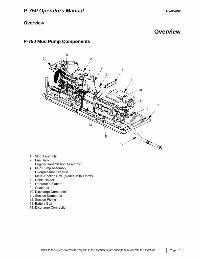
OverviewP-750 Mud Pump Components
1. Skid Assembly2. Fuel Tank3. Engine/Transmission Assembly4. Mud Pump Assembly5. Overpressure Exhaust6. Main Junction Box, (hidden in this view)
2 75mp1015B-drw
7
89
4
10
11
141
63
13
5
12
Page 13Refer to the Safety Awareness Program in this manual before attempting to operate this machine
7. Cable Holder8. Operator’s Station9. Chainbox10. Discharge Dampener11. Suction Dampener12. Suction Piping13. Battery Box14. Discharge Connection

P-750 Operators Manual
Page
Overview
Op
Ow
tion for pthe iAugeual o
Tcatiowitho
Ma
Ma
Sco
ing d
Overview
eration and Maintenance Manual
TITLE: P-750 Operation & Safety Instruction ManualEDITION: 2012Part Number: 75MP10000
nership of Information
American Augers, Inc. reserves all rights to the information in this manual.
The manual cannot be reproduced or photocopied in part or in whole without previous written authoriza-from American Augers, Inc. The use of the manual is restricted to the customer who received it and only urposes of installation, use, and maintenance of the relevant machine. American Augers declares that nformation contained in this manual fits the technical and safety specifications of the machine. American rs disclaims responsibility for direct or indirect damages to persons or property caused when the man-r the machine are used in violation of the information contained herein.
he information contained in the manual refers only to the machine mentioned under “Machine Identifi-n Data” below. American Augers reserves the right to modify or improve the manual and the machines ut notice.
nufacturer Identification Data
AMERICAN AUGERS, INC.135 U.S. Rt. 42, P.O. Box 814West Salem, Ohio 44287 USATel. 419-869-7107 • Fax 419-869-7425Web Site: www.americanaugers.com
chine Identification Data
Type: Mud PumpModel: P-750Serial number: Found on identification plateYear of manufacture: Incorporated as part of the serial number on machines prior to 2010
Listed on serial number plate on machines after 2009
Location of identification plate: See drawing on page 3.
14 Refer to the Safety Awareness Program in this manual before attempting to operate this machine
pe of Document
This manual covers operation, safety and maintenance of the P-750. Operating a directional drill, select-rilling fluid and operating mud cleaning and recycling systems are outside the scope of this manual.

P-750 Operators Manual
O
Overview
Q
Ambe
D
is
U
Le
P
Nth
Nth
verview
ualification of Personnel
After delivery of the machine, a technician from American Augers is available for training the operators. erican Augers is available for further information or instruction. It is expected that customer personnel will
available and ready for training upon the scheduled arrival of the American Augers trainer.
eclaration of Conformity
If required, the Declaration of Conformity is issued at consignment of the machine. A sample document reproduced on page 70. The Declaration of Conformity is not required in most countries.
se of Personal Protective Equipment
gal Disclaimer
Improper operation can result in serious injury, death and damage to the equipment. Personnel should read the manual and/or obtain appropriate training based on their duties.
• Only skilled and authorized personnel should be permitted to transport, operate and maintain the machine.
• Training is available by contacting the American Augers factory.
OTICE: American Augers disclaims any responsibility for damages to persons or property caused by e operation of the machine by untrained personnel.
If personal protective equipment is not used, serious injury or death of personnel can occur. The operator and all other personnel on the jobsite should use proper protective equipment according to their duties.
Page 15Refer to the Safety Awareness Program in this manual before attempting to operate this machine
urpose of Machine
The machine was designed for pumping drilling fluid to directional drills.
OTICE: American Augers disclaims any responsibility for damages to persons or property caused by e operation of this machine in violation of the instructions contained in this manual.

P-750 Operators Manual
Page
Overview
Am
+5°FRMAT
Tra
Op
750
Wa
the imac
Lim
nal w
Req
num
Wa
macvice
NO“Lim
Overview
bient Conditions
Temperature limits: The machine, with factory fill of lubricants, is designed to work in temperatures from to +110°F (-15°C and +43°C). For temperatures not included in this range, contact American Augers. elative humidity: 100%aximum altitude: 6500 feet (2000 m) above sea leveltmospheric conditions should allow adequate visibility within the operating area.he machine should not be operated when lightning is likely.
nsport
The machine should be transported by a truck tractor in accordance with local transportation laws.
eration
It is recommended only one person operates the controls. Other trained personnel may work near the P-if they are wearing appropriate personal protective equipment.
rranty: General Conditions
Warranty is subject to the conditions specified in the warranty certificate. The warranty certificate is on nside of the last page of this manual. If you have questions about the warranty or any part of the hine operation, please contact American Augers.
itations of Warranty
The warranty for all components that are not manufactured by American Augers are subject to the origi-arranties of their manufacturers and not by American Augers.
uest for Service/Support
For service support in or out of the warranty period, contact American Augers. Provide machine model ber, serial number and number of operating hours.
TICE: Modifications to the equipment made by the customer might reduce warranty coverage. See ited Warranty” section beginning on page 71.
16 Refer to the Safety Awareness Program in this manual before attempting to operate this machine
rranty and Service for Diesel Engine
The warranty on the engine is valid worldwide and is supplied by the engine dealer in the area where the hine is sold. Only diesel engine dealers are authorized to perform repairs under warranty, provide ser-and supply spare parts.

P-750 Operators Manual Safety
Safety
SafetySafety Regulations and Practices
This manual contains important information about the safety practices and safe operation of the P-750. All operators must read and understand the Operation and Safety Instruction Manual before starting the machine. Careful adherence to the safety and operating instructions in this manual will help ensure a safe and productive jobsite.
The safety information in this Manual does not replace safety codes, insurance needs, national, provin-cial, state and local laws. Ensure that your machine has the correct equipment required by the local laws and regulations. It is the responsibility of each person working with this equipment to learn and follow all applica-ble local, state, provincial and national safety regulations.
Emergency Procedures
Response to Electrical Strike
• If you are on the machine, stay on it. • Remain calm. • If you are not on the machine, do not touch any part of the machine as it may be highly charged. • Notify public safety authorities to secure the area. • Notify the electric utility company immediately.
NOTICE: American Augers disclaims any responsibility for damages to persons or property caused by operation in violation of safety advice contained in the manual.
EMERGENCY SHUTDOWN: Push the red Emergency Stop button in one of the following locations:• on the Operator’s Console• on the Junction Box• on the Engine Control Panel
All workers should know the locations of the Emergency Stop buttons before starting the machine on the jobsite.
Page 17Refer to the Safety Awareness Program in this manual before attempting to operate this machine
• When the proper utility authorities verify that the power has been disconnected and the work area is safe, you may get off the machine.
Other workers in the immediate area of the machine should not move. The voltage difference between the equipment and the ground, or between a person’s feet may be sufficient to cause injury or death. Do not touch the machine, hoses, drill pipe, water system, mud mixing system or anything connected to the drill as these items may be highly charged.
Response to a Gas Strike
If a gas line strike occurs, evacuate the area immediately. Shut down all engines. Extinguish all flame and sparks immediately. Do not attempt to reverse the bore to break contact as further movement may cause a spark. Contact emergency services and the gas utility company immediately.

P-750 Operators Manual
Page
Safety
Res
caus
Res
Res
occuwith
Bas
1. m
2. 3.
4.
5.
6. F
Safetyponse to a Fiber Optic Strike
If a fiber-optic strike occurs, stop drilling immediately. Do not look into the cut ends of the cable. This can e severe eye damage. Notify the utility owner.
ponse to a Communications Line Strike
If a communications line strike occurs, stop drilling immediately and notify the utility company.
ponse to a Sanitary/Storm Sewer and Water Strike
If a water or sewer line strike occurs, stop drilling immediately. Warn all bystanders that a strike has rred and that they should stay away. Obtain medical attention for personnel who have come into contact sewage. Notify the utility owner immediately.
ic Safety Guidelines
Before using the P-750, all operators should receive thorough training in the use of this equipment. This anual should be used as a training tool.
A copy of this manual should remain with the machine and be accessible to all personnel at all times.Personnel on the jobsite should receive training on safety practices, procedures, safety signs and haz-ards. Operators, support personnel, repair technicians, and visitors should be aware of their responsibil-ities and any restrictions to their activities.All new, inexperienced employees should receive a complete orientation to the jobsite and thorough training in their job duties. Never allow inexperienced personnel to operate or work near the machine unless they are carefully supervised.The meaning of the hazard alert signs on the equipment is explained in “Safety Alerts” section beginning on page 25.
Jobsite hazards could result in serious injury or death. All personnel on the jobsite should use proper protective equipment according to their duties.
18 Refer to the Safety Awareness Program in this manual before attempting to operate this machine
ollow all national, state, provincial and local regulations regarding, but not limited to:
Drilling fluid system operationRotating drill pipeVehicle operationTrench shoring and slopingMobile equipment operationConfined space entryNoise
Hand and power toolsVerification of utilitiesCommunicationsFall protectionSecurity of jobsite and isolation of hazardsMaterial handlingManual lifting

P-750 Operators Manual
S
Safety
(O29coop
7.
8. 9. 10
U
in strbo
tatweva
av
afetyIn the United States, workplace safety is regulated by the Occupational Safety and Health Administration
SHA). OSHA regulations are found in the Code of Federal Regulations, Chapter 29. This is known as CFR1910. Information can be obtained from your Regional U.S. Department of Labor Office. In other untries, the operator is responsible for determining which national, provincial, state and local laws govern erations at the jobsite.
Use required or recommended protective equipment which meets applicable standards when operating this machine:• Hard hats• Safety glasses, goggles, or face shields• Work boots• Work gloves• Highly visible reflective clothing• Hearing protection• Boots and gloves having electrical insulation• Any additional safety equipment mandated by other rules or required by the Owner or regulatory
agencyIf a hazardous situation is suspected, stop work until appropriate corrective action is taken.Use hand signals required for specific jobs. Know who has the responsibility for signaling.
. Post the location and phone number of the nearest aid station or hospital. Have a fire extinguisher and complete first aid kit on site. Have at least one of your workers trained in first aid.
tility Locations
Electric shock and explosion hazard. Have all utility lines marked before you begin to dig. Notify One Call (by calling 811) as well as utility companies that do not subscribe to the One Call system.
• The One-Call system (dial 811 (US only) or 1-888-258-0808 (US and Canada only)) is in place to facilitate identifying appropriate local utility contacts.
• It is the operator's responsibility to follow applicable laws and regulations which govern locating and avoiding existing utilities.
Page 19Refer to the Safety Awareness Program in this manual before attempting to operate this machine
Before beginning any drilling project, have local utility companies mark the location of utility lines buried the area. Design the bore profile to maintain acceptable clearances between underground utilities and uctures and the final reamed hole. Carefully consider possible migration of the backreamer from the pilot re toward the utility due to excessive steering or a tight radius when establishing clearances.
The One-Call system (dial 811 (US only) or 1-888-258-0808 (US and Canada only)) is in place to facili-e identifying appropriate local utility contacts. Additionally, the Pipeline Association for Public Awareness bsite has several references for excavators at http://www.pipelineawareness.org/excavators. Their “Exca-tion Safety Guide” describes best practices and contains a guide to state contacts and regulations.
It is the operator's responsibility to follow applicable laws and regulations which govern locating and oiding existing utilities.

P-750 Operators Manual
Page
Safety
Ov
zatioalwaknohighope
Be
Op
Op
Ma
•
Safety
erhead Hazards
Overhead lines must be avoided. Overhead lines are of particular concern during mobilization/demobili-n, loading and unloading heavy equipment and while handling drill pipe. If the voltage is unknown, ys maintain at least 20 feet (6 m) of separation between equipment and power lines. If the voltage is wn, OSHA regulations outline the required minimum separation in the United States. If necessary, place ly visible markers on either side of the overhead hazard or designate an individual to notify equipment rators as they approach.
fore Starting the Machine
• Complete all servicing prescribed in this Operator’s Manual and Attachment A: Diesel Engine Manual.• Securely connect all fluid lines before starting the machine. • Check that all hydraulic fittings, bolts, and nuts are tight.• Remove all loose objects stored in or on the machine. • Remove all objects which do not belong in or on the machine and its equipment. • Ensure that all protective guards, doors, etc. are in place.
erating Precautions
• Place all machine controls in the neutral or off position before starting the engine.• Do not start the machine until all personnel are away from moving parts. • Check the operation of all machine controls before using the machine.
erator’s Responsibilities
• It is the responsibility of the operator to read and understand the Operator’s Manual and other informa-tion provided and use the correct operating procedure. Machines should be operated only by qualified operators and trained helpers.
• Understand and obey all applicable national, provincial, state, and local codes and regulations. • Point out each of the safety signs on the machine and ensure that the crew understand them. • Make sure all operating personnel observe and use safe operating practices. • Ensure that all personnel and objects stay away from rotating or moving parts. • Never leave the operator’s station while the engine is running.
20 Refer to the Safety Awareness Program in this manual before attempting to operate this machine
• Do not operate the machine while under the influence of alcohol or drugs. • Turn off the machine at the first sign of malfunction or hazardous condition.
terial Handling Precautions
• Use appropriate lifting equipment for the size of the load.• Discard and replace damaged or worn lifting equipment (e.g., slings, chains, ropes, etc.) Use a tether line to stabilize the load and minimize twisting and turning.
• Stand away from suspended loads. Do not approach the load until it has been lowered to hand-height.• Use proper hand signals and know who has the responsibility for signaling.

P-750 Operators Manual
S
Safety
D
M
Tr
N
80
afety
rilling Precautions
• Identify and avoid potential pinch points on the drill rig and support equipment.• Stay away from the rotating drill string at all times.
aintenance Precautions
• Turn off the power source and relieve system pressures before doing maintenance. • Allow the machine to cool before servicing. Hydraulic components, engine, radiator and exhaust sys-
tems can get hot enough to cause serious injury.• Use proper lock out and tag out procedures when doing maintenance.• Follow manufacturer’s recommended maintenance procedures. • Allow only properly trained personnel to perform maintenance activities.• Do not modify the machine in any way. • Repair or replace damaged or missing protective guards, doors, etc. • Replace all missing, illegible, or damaged safety signs. Keep all safety signs clean. • Use a piece of cardboard or wood to check for pressurized leaks to prevent fluid penetrating the skin.• Seek medical attention immediately if hydraulic fluid escaping under pressure has penetrated the skin.
Even if the injury seems minor, prompt medical treatment by a physician familiar with this injury is essential. This is a serious condition which can cause serious injury and possibly death.
ansporting Precautions
• Inspect all tractor trailers being used to transport the machine, including but not limited to checking the brakes, tires, tire pressure and lights.
• Remove or secure loose items so they cannot fall off during transport.
oise Level Safety
Exposure to high noise levels may cause hearing loss. Wear appropriate hearing protection.
Page 21Refer to the Safety Awareness Program in this manual before attempting to operate this machine
The sound pressure measured according to ISO 11202:1993, ISO 3746:1995, IEC 651:1979 and IEC 4:1985 is 102 dB(A).

P-750 Operators Manual
Page
Safety
Haz
We
IMP• D• D
s• A
Safety
ardous Chemicals
lding Safety
Explosion hazard. Flammable solvents could ignite if placed near fire, sparks or other ignition sources. Keep flammable solvents in closed containers and away from fire, sparks and ignition sources.
Inhalation hazard. Dust from drilling fluid additives such as bentonite may irritate the respiratory system or lungs. Prolonged exposure may damage the respiratory system. Use respiratory protection and dust resistant safety goggles.
ORTANT:o not use containers that can leak.o not drain fluids on the ground or dump them into sewage systems, streams, rivers, lakes or the ea.lways follow laws and regulations for proper disposal of waste materials.
Workers can encounter hot surfaces, fire, noxious fumes and other hazards when welding.
These practices can help increase safety when welding:• Follow established welding safety practices and regulations• Assign another worker to “fire watch”• Wear appropriate protective equipment (face shield, fire resistant clothing, etc.)
22 Refer to the Safety Awareness Program in this manual before attempting to operate this machine
• Ensure adequate ventilation• Have a first aid kit nearby

P-750 Operators Manual
S
Safety
D
Allsa
wh
opeqrea
G
daloc
ingoneqracan
IMc
afety
angerous Zones -- Safe Distances
A dangerous zone is any zone inside or near the machine where health, safety and security risks exist. personnel on the jobsite should be advised of these zones, the hazards they may encounter and the fety precautions which are required or recommended.
Hazardous Area: All areas from which a person could touch parts of the machine when it is operating or en maintenance is being performed. On electrical jobsites, wear appropriate protective equipment.
Electrically Charged Safe Distance: 25 feet (8 m) from the drill hole. Personnel in this zone during drilling erations are at risk in the event an electric line is struck. On electrical jobsites, wear appropriate protective uipment (insulated boots and gloves). All other personnel must stay out of this zone during drilling or back-ming or any time when an electric line could be struck.
rounding
Metal components on a drill rig site can become electrically charged for a number of reasons: faulty or maged wiring, inductive capacitance from generators, motors, motor drives, transformers, contact with al distribution wiring or underground cables etc. Care should be taken to avoid electrocution.
Electrocution Hazard. Personnel are at risk if an electric line is struck during drilling. All personnel must wear appropriate protective equipment (electrical insulating boots and gloves) on the job site.
Electrocution hazard. Improperly grounded components may become electrically charged. Serious injury or death could occur. Bond all fixtures together and ground to a single stake before starting the engine.
• . Follow all local codes and regulations with regard to bonding and grounding.
Page 23Refer to the Safety Awareness Program in this manual before attempting to operate this machine
All metal components on a drill rig site should be bonded together as shown in the drawing below. Bond- will reduce the electric potential difference between components with respect to any other components the site. Current will not flow between two sections that are at the same electric potential. All remote uipment that is in close proximity to the drill rig must also be electrically bonded to the drill rig, i.e. pipe ks, mud pumps etc. This will reduce the risk of shock to any personnel who might contact both the drill rig
d the remote equipment.
PORTANT: For additional information on electrical hazards, bonding and grounding, you may wish to onsult publications from the U.S. Occupational Safety and Health Administration.a b
a. Controlling Electrical Hazards, U.S. Department of Labor, OSHA 3075.b. Protection from Step and Touch Potentials, 29CFR1910.269 Appendix C.

P-750 Operators Manual
Page
Safety
Typic
Safety
al Bonding Scheme on a Directional Drilling Site
Bonding Cable
Ground Stake
Bonding Cable Bonding Cable
Dumpster
Mud SystemCrane
Drill Pipe
Drill Rig
CabinPower Unit
Pit
Bore Path
24 Refer to the Safety Awareness Program in this manual before attempting to operate this machine

P-750 Operators Manual Safety
Safety Alerts
Machine may become electrically charged.
Machine may become electrically charged.
Diesel engine exhaust warning. Explosion hazard. Call 811 before you dig.
Rotating parts can cause injuries. Pump may be damaged if allowed to run dry.
Page 25Refer to the Safety Awareness Program in this manual before attempting to operate this machine

P-750 Operators ManualNotes
Notes
NOTES:
Page 26 Refer to the Safety Awareness Program in this manual before attempting to operate this machine

P-750 Operators Manual Controls
Machine Controls
ControlsSafety Switches
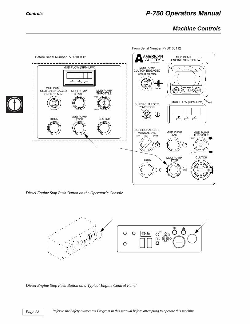
There are push buttons at four different locations that stop the diesel engine on the P-750.
Diesel Engine Stop Push Button on the Junction Box
MUD PUMPSTOP
STOP
60M
P97
24-ju
nctio
nbox
MUD PUMPCLUTCH
HORN
Page 27Refer to the Safety Awareness Program in this manual before attempting to operate this machine
Diesel Engine Stop Push Button on the Mud Pump Control Box
EMERG STOP
STOP
60M
P97
24-c
lutc
hbox
P-750 Operators Manual
Page
Controls
Dies
Dies
75
Machine Controls
el Engine Stop Push Button on the Operator’s Console
MUD PUMP
STOP
STOPHORNCLUTCH
MUD PUMPSTART
MUD PUMPTHROTTLE
FAST
MUD FLOW (GPM-LPM)SUPERCHARGER
POWER ON
SUPERCHARGERMANUAL SW.
OFF RUN START
MUD PUMPCLUTCH ENGAGED
OVER 10 MIN.
MUD PUMPENGINE MONITOR
SLOW
60M
P97
14-c
ontro
lpan
el
MUD FLOW (GPM-LPM)
MUD PUMPCLUTCH ENGAGED
OVER 10 MIN.MUD PUMP
STARTMUD PUMPTHROTTLE
FAST
SLOW
MUD PUMPSTOPHORN CLUTCH
Before Serial Number P750100112
From Serial Number P750100112
MP9710 - before SN10-ctrlpanel
28 Refer to the Safety Awareness Program in this manual before attempting to operate this machine
el Engine Stop Push Button on a Typical Engine Control Panel

P-750 Operators Manual
M
Controls
B
sw
the
IM•••
achine Controls
attery Switch
The battery switches are located on the side of the battery box as shown in the drawing below. The itch connects and disconnects the batteries from the electrical system.
• Rotate to the right to connect. • Rotate left to disconnect. • The battery switch must be in the ON position before starting the engine.• Turn the battery switch OFF after you stop the engine. Remove the key if so equipped.• When performing maintenance, install a padlock through the tab and follow proper lockout-tagout pro-
cedures.
PORTANT: DO NOT disconnect the batteries while the engine is running. DO NOT try to stop the engine with this switch. You can damage the electrical system. During maintenance, turn the switch OFF and use proper lockout and tagout procedures.
ON
OFFLocking Tab
Page 29Refer to the Safety Awareness Program in this manual before attempting to operate this machine
In earlier models, the battery switch does not have the locking tab. When performing maintenance, turn battery switch OFF after you stop the engine. Remove the key from the Engine Control Panel.
8ep02900-2=24505-T[1]-BattDisconLockout

P-750 Operators Manual
Page
Controls
P-7
Machine Controls
50 Operator’s Station
MUD FLOW (GPM-LPM)
MUD PUMPCLUTCH ENGAGED
OVER 10 MIN.MUD PUMP
STARTMUD PUMPTHROTTLE
FAST
SLOW
MUD PUMPSTOPHORN CLUTCH75
MP
9710
- be
fore
SN
10-c
trlpa
nel
8 9
23
10
6 Before Serial Number P750100112
1
MUD PUMP
MUD FLOW (GPM-LPM)SUPERCHARGER
POWER ON
SUPERCHARGER
MUD PUMPCLUTCH ENGAGED
OVER 10 MIN.
MUD PUMPENGINE MONITOR
7
8
4
5
6
ontro
lpan
el
From Serial Number P750100112
30 Refer to the Safety Awareness Program in this manual before attempting to operate this machine
MUD PUMP
STOP
STOPHORNCLUTCH
STARTMUD PUMPTHROTTLE
FAST
MANUAL SW.OFF RUN START
SLOW
9
10
2 1
3
60M
P97
14-c

P-750 Operators Manual
M
Controls
1
2
3
4
5
61
7
8
9
1
achine Controls
Control Function
. Mud Pump Stop • Stop the mud pump engine: push button• Enable engine start: button must be pulled out
. Mud Pump Start Start mud pump: push buttonNote that the ignition switch on the Engine Control Panel must be in the “ON” position.
. Horn Sound horn: push button
. Supercharger Manual Switch When this switch is turned off, it overrides control by the mud pump system. The switch should remain in the “RUN” position during normal operations.
. Supercharger Power On Light is lit when the supercharge pump should be running. Verify that the supercharger is operating. If the supercharger fails to start or stops running, damage to the machine could result.
. Mud Pump Clutch Engaged over 0 Min.
An audible alarm alerts the operator that the Mud Pump clutch is pushed in and the engine has been running in gear for over 10 minutes. Either: • pull out the clutch button and begin mud pump flow• shift into neutral to idle the engine• turn off the engine.
. Mud Pump Engine Monitor Engine Management System Displaya for the engine.
. Mud Pump Flow (GPM-LPM) Displays the Mud Pump flow rate in Gallons per Minute (GPM) or Liters per Minute (LPM). It is set at the factory to GPM.
. Mud Pump Throttle • Increase engine speed and mud flow rate: push control up• Decrease engine speed and mud flow rate: pull control down
0. Clutch Remotely engage and disengage the Mud Pump clutch.• Push in (like you would push in the clutch pedal on an automo-
bile) so you can shift into gear or neutral
Page 31Refer to the Safety Awareness Program in this manual before attempting to operate this machine
a. The displays can be configured to show various parameters from the engines. These include engine RPM, engine hours, machine hours, coolant temperature, oil pressure and throttle position. Use the four keys below the display to change the information shown. Refer to Attachment 2: “Murphy Power System User Guide”, Attachment 3: “Murphy Troubleshooting” and Attachment 4: “Murphy Error Messages”.
• Pull out with the engine in neutral to run at idle or with the engine in gear to begin mud pump flow

P-750 Operators Manual
Page
Controls
P-7
1. M
Machine Controls
50 Junction Box
Control Function
ud Pump Stop • Stop the mud pump engine: push button• Enable engine start: button must be pulled out
MUD PUMPSTOP
STOP
60M
P97
24-J
ctB
ox
1
32 Refer to the Safety Awareness Program in this manual before attempting to operate this machine
P-750 Operators Manual
M
Controls
P
1
2
3
achine Controls
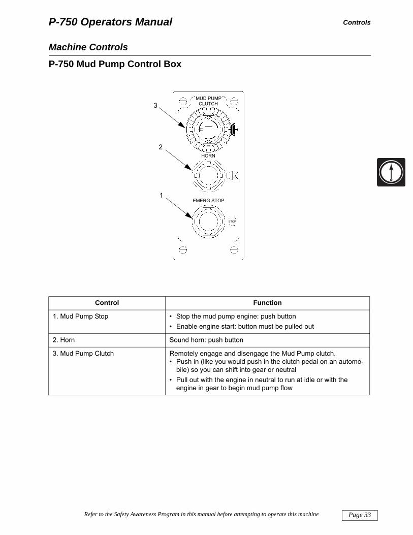
-750 Mud Pump Control Box
Control Function
. Mud Pump Stop • Stop the mud pump engine: push button• Enable engine start: button must be pulled out
. Horn Sound horn: push button
. Mud Pump Clutch Remotely engage and disengage the Mud Pump clutch.• Push in (like you would push in the clutch pedal on an automo-
MUD PUMPCLUTCH
HORN
EMERG STOP
STOP
60M
P97
24-C
lutc
hBox
1
2
3
Page 33Refer to the Safety Awareness Program in this manual before attempting to operate this machine
bile) so you can shift into gear or neutral• Pull out with the engine in neutral to run at idle or with the
engine in gear to begin mud pump flow

P-750 Operators Manual
Page
Controls
Typ
1. E
2. I
3. D
4. T
5. E
6. C
7. D
Machine Controls
ical Engine Control Panels
Control Function
mergency Stop Button • Stop the mud pump engine: push button• Enable engine start: button must be pulled out
gnition Switch • Stop: Turn the key straight up• Run: Rotate key 45° to the right• Start: Rotate key 90° to the right
iagnostic/Warning Light If light turns on, follow instructions in the Diesel Engine manual or contact the engine manufacturer.
hrottle • Increase engine speed: push control up• Decrease engine speed: pull control down
ngine Hours Meter Displays the number of accumulated hours on the engine.
ircuit Breakers/Fuses Follow instructions in the Diesel Engine manual or contact the engine manufacturer.
1
24
5
3
6
13
6 7 4 2 5
34 Refer to the Safety Awareness Program in this manual before attempting to operate this machine
iesel Particulate Filter Indicators Controls related to regenerating the diesel particulate filter which removes particulate matter and soot from exhaust gases. Follow instructions in the Diesel Engine manual or contact the engine manufacturer.

P-750 Operators Manual Operations
Preparation
OperationsSite Preparation and Set Up
Scrape an area 10 feet wide x 26 feet long (3 x 8 m) to a level grade so that the P-750 is located 50 to 75 feet (15.2 to 23 m) from the point where the mud hoses attach to the directional drill.
Connect all components on the drill site with a bonding cable and install a ground stake.
Hose Connections
1. Securely connect the suction hose of the P-750 mud pump to the outlet (discharge) of the supercharger pump.
2. Securely connect the P-750 discharge to the drilling fluid intake on the directional drill. The discharge hose connection is a hammer union. It must be tightened securely by hitting the ears of each collar with a hand sledge hammer.
3. Route the hoses with a minimum number of bends. Sharp bends in the hose reduce the flow to direc-tional drill. The mud cleaning system should supply drilling fluid at 25-30 PSI (975 GPM), minimum, to the inlet of the P-750 pump.
IMPORTANT: • Liquid contents of these hoses is under high pressure. Work on these hoses only when the pump is off.• Pumping drilling fluid with sand content greater than 1/2% can cause excessive wear to the fluid
pumping system.• Ensure valves in the mud piping are in the proper position so as not to damage the system when the
mud pump is started.
Connect to drilling fluid intake on drill
ct
Page 35Refer to the Safety Awareness Program in this manual before attempting to operate this machine
Connect to supercharger discharge
75m
p101
5B-d
rw h
osec
onne

P-750 Operators Manual
Page
Operations
backto coloca
PreparationThe machine is also equipped with a fitting through which drilling fluid can escape if there is a pressure up in the system (see “Mud Pump Pressure Relief Valve” section beginning on page 43). You may wish nnect a suitable hose to this fitting to route the fluid back to the mud tank. The drawing below shows the
tion of this fitting.
Connect hose here to route drilling fluid back to the mud tank when pres-sure relief valve has been activated
36 Refer to the Safety Awareness Program in this manual before attempting to operate this machine
P-750 Operators Manual Operations
Starting the P-750
Starting the P-750
A manufacturer's manual for the diesel engine is supplied with the P-750. The following instructions cover general engine starting procedures. Consult the manufacturer’s manual for detailed starting and stop-ping procedures, engine maintenance and repair instructions.
1. If you have not already done so, verify that the ground stake is installed properly.2. Confirm that all the fluid connections to and from the pump are correct. Check that the valves in the pip-
ing are in the correct position to prevent damage to the system when the system is started.3. Unplug the block heater, if connected. 4. Disconnect all battery chargers.5. Plug the cable from the mud pump cable holder into the Operator’s Console.6. Pull OUT the emergency stop buttons on the Operator’s Console, Junction Box, Mud Pump Control and
in the Engine Control Panel. The engine will not start if any emergency stop button is pushed in.7. Check the engine oil level, coolant level and the diesel fuel level. DO NOT let the diesel engine fuel tank
run dry. If the tank is dry, bleed the fuel system. Refer to Attachment 1: “Diesel Engine Manual” for instructions.
8. Check the oil level in the mud pump and chain reducer box. Add oil if necessary.
Signal lights and operator displays warn of potential operating problems. If ignored, damage to the machine could result. In case of unusual noise, abnormal pressure values, or if signal lights appear, stop the engine immediately and carry out necessary repairs.
Do not use starting fluid (ether). Immediate engine damage and personal injury may result.
Page 37Refer to the Safety Awareness Program in this manual before attempting to operate this machine
9. Switch all controls OFF or put them in neutral. Ensure that the gear shift lever on the mud pump trans-mission is in neutral.
10. Turn the Battery switch to the ON position.

P-750 Operators Manual
Page
Operations
11. ••
12.
the a
ableare 2The See
Starting the P-750You may start the engine from the Engine Control Panel Turn the ignition key 90° to the right to start the engine. When the engine starts, release the key. No throttle action is required during starting. The engine sys-
tem provides the correct amount of fuel. • If the engine fails to start in 30 seconds, release the key switch and wait 2 minutes. This will allow the
starter motor to cool. Then repeat the start process.
Alternatively, you may start the engine from the Operator’s Console.• On the engine panel, turn the ignition key to the right to enable start. • At the Operator’s Console, push the Mud Pump Start button.
Let the engine run at idle (≤900 rpm) for at least ten minutes for proper warm-up and to build pressure in ir circuit.
COLD WEATHER NOTE: The block heater on the engine should be set at 85°F (30°C) if it is an adjust- thermostat type. Newer models are preset at the factory and have no adjustment. These block heaters 40 volt models and require a similar power source. Plug in the block heater at the end of the day’s shift.
heater will keep the water jacket coolant warm to 85°F (30°C) which will make starting the engine easier. Attachment 1, Diesel Engine Manual for information on using the engine block heater.
38 Refer to the Safety Awareness Program in this manual before attempting to operate this machine
P-750 Operators Manual Operations
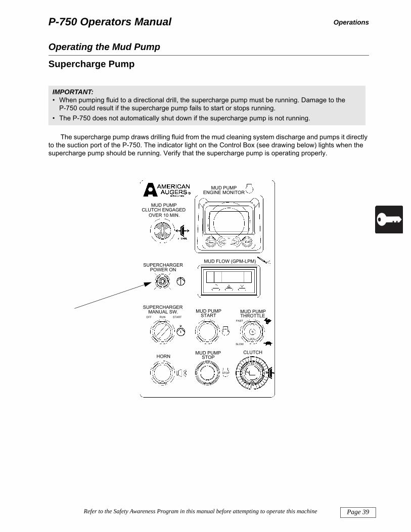
Operating the Mud Pump
Supercharge Pump
The supercharge pump draws drilling fluid from the mud cleaning system discharge and pumps it directly to the suction port of the P-750. The indicator light on the Control Box (see drawing below) lights when the supercharge pump should be running. Verify that the supercharge pump is operating properly.
IMPORTANT: • When pumping fluid to a directional drill, the supercharge pump must be running. Damage to the
P-750 could result if the supercharge pump fails to start or stops running. • The P-750 does not automatically shut down if the supercharge pump is not running.
MUD PUMPSTOPHORN
CLUTCH
MUD PUMPSTART
MUD PUMPTHROTTLE
FAST
MUD FLOW (GPM-LPM)SUPERCHARGER
POWER ON
SUPERCHARGERMANUAL SW.
OFF RUN START
MUD PUMPCLUTCH ENGAGED
OVER 10 MIN.
MUD PUMPENGINE MONITOR
SLOW
Page 39Refer to the Safety Awareness Program in this manual before attempting to operate this machine
STOP

P-750 Operators Manual
Page
Operations
Ad
amo
8N
Starting the P-750
justing the Flow Rate
Select the proper transmission gear to get the desired mud pump flow rate (see chart below left). The unt of drilling fluid flowing through the system can be controlled by adjusting the engine throttle.
P41591-gear chart60
MP
9714
-con
trolp
anel
Before Serial Number P750100112
From Serial Number P750100112
40 Refer to the Safety Awareness Program in this manual before attempting to operate this machine
75M
P97
10 -
befo
re S
N10
-ctrl
pane
l

P-750 Operators Manual
S
Operations
O
exde
tarting the P-750
peration When Adding or Removing Drill Pipe
The P-750 is equipped with an alarm which sounds when the length of time the clutch is engaged ceeds 10 minutes. To minimize sounding the alarm, follow the appropriate procedure from the two scribed below depending on the time needed to change the drill pipe.
MUD PUMPCLUTCH
HORN
EMERG STOP
From Serial Number P750100112
Before Serial Number P750100112
Throttle
Throttle
Clutch
Clutch
Clutch
Page 41Refer to the Safety Awareness Program in this manual before attempting to operate this machine

P-750 Operators Manual
Page
Operations
Add
1. 2. P3. 4. P
d5.
Add
1. 2. P3. 4. 5. 6. 7. S
8. P
9.
Starting the P-750/remove section of drill pipe in < 10 minutes
Throttle the mud pump engine down to an idle (≤900 rpm). ush the “Clutch” button IN. This stops the pump from rotating and pumping drilling fluid.
Add or remove the section of pipe. ull the “Clutch” button OUT. This will restart the desired flow of drilling fluid from the mud pump to the irectional drill.
Move the throttle lever to bring the engine up to the desired rpm.
/remove section of drill pipe in > 10 minutes
Throttle the mud pump engine down to an idle (≤900 rpm). ush the “Clutch” button IN. This stops the pump from rotating and pumping drilling fluid.
Shift the transmission into neutral.Pull the “Clutch” button OUT.Add or remove the section of pipe. Push the “Clutch” button IN.
hift the transmission into the desired gear. This will restart the flow of drilling fluid from the supercharge pump to the P-750.
ull the “Clutch” button OUT. This will restart the desired flow of drilling fluid from the mud pump to the directional drill.Move the throttle lever to bring the engine up to the desired rpm.
42 Refer to the Safety Awareness Program in this manual before attempting to operate this machine

P-750 Operators Manual
S
Operations
M
vaanit uca
IM•
tarting the P-750
ud Pump Pressure Relief Valve
The variable setting pressure relief valve is set at the factory to 1750 psi (120 bar).
If a clog downhole results in a pressure back-up, the pressure will spike and shear the pin on the relief lve. This will allow fluid to pass through the relief valve, back into the mud tank. Shut down the mud pump d resolve the reason for the relief valve tripping. Before resuming operations, replace the shear pin. Insert nder the cap through the bar with holes at 1750 psi. A pack of 10 shear pins is provided. Additional pins
n be ordered from American Augers’ Parts Department.
PORTANT: Do not set pressure relief higher than 1750 psi (120 bar). Doing so could void the warranty on the
pump.
Page 43Refer to the Safety Awareness Program in this manual before attempting to operate this machine

P-750 Operators ManualOperations
End of Pumping Operations
Stopping the Mud Pump Engine
1. Throttle the mud pump engine down to an idle (≤900 rpm).2. Push the Clutch button IN. This stops the pump from rotating and pumping drilling fluid.3. Shift the transmission to neutral.4. Pull the Clutch button OUT.5. Run at idle speed for 5 to 10 minutes to cool down the engine.6. If you expect freezing temperatures, flush the pump with clear water, and add antifreeze to the pump.
Turn the pump over 3 or 4 revolutions.7. Turn the ignition key to OFF to shut down the engine.8. Turn the Battery Switch to OFF.
Page 44 Refer to the Safety Awareness Program in this manual before attempting to operate this machine

P-750 Operators Manual Storage and Transport
Machine Storage and Transport
Storage and TransportMinimum Storage Space Required
Consult the “Specifications” section beginning on page 65 for the dimensions and weight of the P-750 to establish storage space requirements. The surface must be firm enough to support the weight of the machine and prevent sinking.
Storage Site Conditions
If the machine has been lubricated, it can be stored uncovered for up to 30 days. Protect the machine from salty or acid environments, solvents, gas, flammable liquids and explosives.
For periods longer than 30 days, the machine should be stored in a covered, dry area.
The temperature ranges recommended for storage are between 32°F and 120°F (0°C to 50°C). Refer to Attachment 1: Diesel Engine Manual for temperatures outside this range.
Preparations for Storage
For short-term storage, i.e. periods less than 30 days:
1. Clean the machine as described in the “Cleaning” section beginning on page 47.2. Make sure there is no water or drilling fluid in the drilling fluid course. If freezing temperatures are
expected, precharge the drilling fluid system with antifreeze when the machine is not in use. 3. Eliminate sediment and water from the tanks (diesel fuel and oil). 4. Lubricate the entire machine according to the 10 Hour Inspection and Maintenance schedule. Coat all
exposed hydraulic cylinder rods with oil to protect against corrosion.
For storing longer than 30 days, follow the procedures for short-term storage plus these additional steps:
1. Store the machine in a covered, dry location.2. Follow manufacturer’s instructions for long-term storage of a diesel engine.3. Remove and store the batteries where the temperature will remain between 32°F and 105°F (0°C to
45°C).
Page 45Refer to the Safety Awareness Program in this manual before attempting to operate this machine
4. Completely fill all gear boxes with lubricant.
P-750 Operators Manual
Page
Storage and Transport
Tra
be paccosible
Lift
Machine Storage and Transport
nsportation
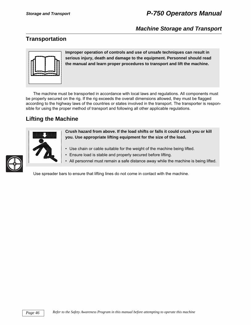
The machine must be transported in accordance with local laws and regulations. All components must roperly secured on the rig. If the rig exceeds the overall dimensions allowed, they must be flagged rding to the highway laws of the countries or states involved in the transport. The transporter is respon- for using the proper method of transport and following all other applicable regulations.
ing the Machine
Use spreader bars to ensure that lifting lines do not come in contact with the machine.
Improper operation of controls and use of unsafe techniques can result in serious injury, death and damage to the equipment. Personnel should read the manual and learn proper procedures to transport and lift the machine.
Crush hazard from above. If the load shifts or falls it could crush you or kill you. Use appropriate lifting equipment for the size of the load.
• Use chain or cable suitable for the weight of the machine being lifted. • Ensure load is stable and properly secured before lifting.• All personnel must remain a safe distance away while the machine is being lifted.
46 Refer to the Safety Awareness Program in this manual before attempting to operate this machine

P-750 Operators Manual Maintenance
General Maintenance
Maintenance
Hydraulic oil, gearbox oil, diesel engine oil, pin and bearing greases, diesel engine cooling liquid, battery liquids and fuel should be handled with care. Consult Material Safety Data Sheets. Dispose of spent fluids according to laws and regulations. Take appropriate precautions to ensure that these fluids do not leak or spill on the ground or into sewage systems, streams, rivers, lakes or the sea.
Engines, muffler, gearboxes and the hydraulic system can reach very high temperatures. Do not attempt maintenance immediately after stopping work. Wait until the parts are cool.
For additional drawings, diagrams and explanations necessary for maintenance and repair, contact the factory.
Qualification of the Technician
Ensure that all field personnel conducting visual inspections of the machine have adequate training to enable them to identify problems and that they have read this manual.
The maintenance technician must be trained in mud pump operations. The maintenance technician is responsible for conducting maintenance with suitable test and repair equipment, personal protective equip-ment and attention to safety hazards.
Cleaning
Failure to turn off the machine and lockout systems before doing maintenance work may result in personal injury or death. Turn off power, relieve system pressures, and turn the Battery switch to the OFF position. Remove key from the Engine Start switch. Use proper lockout and tagout procedures before working on the machine.
Water can damage sensitive electronic components. Do not spray water against electronic components and control panels.
Page 47Refer to the Safety Awareness Program in this manual before attempting to operate this machine
General Cleaning
Clean all the marking plates as well as all lighting devices. Do not direct water spray inside the muffler or the air filter, against electric components and control panels or on caps and open tanks. Do not use acid or abrasive solutions. Keep caps and covers for hydraulic connections clean. Contamination of hydraulic oil will negatively impact performance of your P-750.

P-750 Operators Manual
Page
Maintenance
Cle
gaugthe p
Cle
petrothe cman
Cle
cleaFailuand
We
weldbelo
IMP• D
s• D• F
a
General Maintenanceaning Plastic and Resin Parts
Avoid using gasoline, kerosene, paint thinner and similar materials when cleaning the instrument cluster, es, console, plastic windows, etc. These materials will cause discoloration, cracking or deformation of art being cleaned. Use ONLY water, mild soap and a soft cloth when you clean these parts.
aning Hydraulic Connections
Hydraulic couplings and protective caps must be kept clean and free of all debris. Use an evaporative, leum-based aerosol cleaner. When hydraulic couplings are not connected, replace protective caps on onnectors and hose ends. Failure to keep the hydraulic couplings clean could impact equipment perfor-ce, cause serious damage and may void the product warranty.
aning Electrical Connections
Electrical connectors and dust caps must be kept clean and dry. Use a high quality electrical contact ner. When electrical cables are disconnected, replace dust caps on the connections and cable ends. re to keep the electrical connectors clean could impact equipment performance, cause serious damage may void the product warranty.
lding
Consult the factory for additional information about preheating or post weld heat treating requirements if ing is necessary in cooler temperatures. Welding should not be done when the ambient temperature is w 0°F.
ORTANT:isconnect all electrical connections before welding. Damage can occur to processor and electrical ystem if electrical components are connected during welding.o not weld near the tanks and flammable liquids.ailure to follow welding procedure can cause damage to electric and mechanical components. Dam-ge to components due to improper procedures is not covered under warranty.
48 Refer to the Safety Awareness Program in this manual before attempting to operate this machine

P-750 Operators Manual
G
Maintenance
A
theSplinon
eneral Maintenance
pproved Replacement Fluids
When adding or replacing fluids, use the same fluid that is in the system. Avoid mixing different fluids as y may be incompatible. Use the fluid in the table below or select an equivalent from the American Augers ecifications (see Attachment 5: American Augers Lubrication Guide). The compatibility table is a guide-e. It lists the compatibility of the main thickener systems used in the industry. Contact the factory for advice the compatibility of a new grease with the one in service.
Approved Replacement Fluids(Temperature range 5°F to 110°F [-15°C to 43°C])
Consult factory for specifications at temperatures outside temperature range
Engine Oil Shell Rotella® T 15W40 AA Specification 401
Engine Antifreeze Shellzone® 60%, Water 40% AA Specification 601
Transmission Fluid Shell Spirax® GSX 50 AA Specification 502
Pump Chainbox Hydraulic Oil Shell Tellus® T ISO 46 AA Specification 202
Pump Crankcase Oil Shell Omala® ISO VG 68 AA Specification 101
Linerwash Antifreeze Pitt-Penn RV Antifreeze AA Specification 603
Grease Shell Retinax® 00 TL AA Specification 301
Page 49Refer to the Safety Awareness Program in this manual before attempting to operate this machine

P-750 Operators ManualMaintenance
Scheduled Maintenance
P-750 Maintenance ScheduleAfter 10* 50* 500* 1000*
Function each job hours hours hours hoursCycle Emergency Stop Buttons X
Leak Check Valves, Hoses, Fittings, Cylinders XEngine: Check Fuel Level X
Engine: Check Coolant Level XEngine: Check Crankcase Oil Level X
Check Battery Water Level XEngine: Inspect Air Filter Service Indicator X
Check Pump Crankcase Oil Level XCheck Pump Chainbox Oil Level X
Check Hydraulic Oil for Lube Pump Level XCheck Linerwash Antifreeze Level X
Inspect Drive Shaft XCheck Transmission Fluid Level X
Lubricate Drive Shaft XTighten Pump Flange Bolts X
Engine: Change Oil and Filter XEngine: Test Coolant X
Engine Belts: Check Tension XClean or Replace Air Filter Elements X**
Tighten Drive Shaft Fasteners XEngine: Change Fuel Filters X
Engine: Clean Cooling System XEngine: Replace Coolant X
Engine: Change Transmission Fluid XChange Pump Chainbox Oil X
Change Pump Crankcase Oil XChange Hydraulic Oil for Lube Pump X
Change Linerwash Antifreeze XDrain and Flush Mud Hoses X
Page 50 Refer to the Safety Awareness Program in this manual before attempting to operate this machine
NOTES:* Do not exceed the indicated number of hours without performing the required maintenance**, Unless filter indicator shows change required at a more frequent interval

P-750 Operators Manual
S
Maintenance
10
Cy
Ma
En
wipre
enanare
the
En
IMiz
cheduled Maintenance
Hour Inspection and Maintenance
Perform the 10 hour inspection and maintenance items in the Maintenance Schedule.
cle Emergency Stop (Disable) Buttons
Verify that all emergency stop buttons are working properly. Perform an operating check of all controls. ke necessary repairs before starting operations.
gine: Check Fuel Level
Begin each shift with a full tank of fuel. To prevent dirt and water from reaching the injection parts which ll cause damage and decrease performance, use clean fuel and service the fuel filter at regular intervals as scribed in the Maintenance Schedule.
Use Number 2 Diesel fuel in your engine (with 50 Cetane or higher). Using other fuels will result in loss of gine power and high fuel consumption. When the temperature is very cold, using a mixture of Number 1 d Number 2 fuel is acceptable for a short period. See your fuel dealer for winter fuel requirements in your a.
Diesel fuel conditioner is available from your dealer. Instructions for the use of the fuel conditioner are on container. The use of diesel fuel conditioner will:
Clean fuel injectors, valves and manifolds for increased service lifeDisperse insoluble gummy deposits that can form in the fuel systemSeparate moisture from the fuelStabilize fuel in storage
gine: Check Coolant Level
Hot coolant can spray out and cause serious injury. Do not remove radiator cap while the engine is hot. Wait for the engine to cool.
• Slowly open the radiator cap and allow pressure to escape slowly.• Always wear face protection (face shield or goggles) when cleaning radiator fins
with compressed air or pressure washer.
Page 51Refer to the Safety Awareness Program in this manual before attempting to operate this machine
PORTANT: Water quality is important to the performance of the cooling system. Use distilled, deion-ed or demineralized water when mixing with coolant concentrate.

P-750 Operators Manual
Page
Maintenance
Eng
1.
2. 3. 4. R
• C• C
a• A• A
c
IMP• B• R
f
Scheduled Maintenance
ine: Check Crankcase Oil Level
Check that the engine oil is at the maximum level and that there is no contamination.
The mud pump should be on a flat, level surface. Engine oil should be checked while the oil is warm. DO NOT check the engine oil when the engine is hot.Remove the engine oil dipstick and wipe off oil. Reinsert dipstick.Remove dipstick and read the oil level. If level is at the ADD mark or below, oil must be added.
emove the oil filler cap and add oil sufficient to bring the crankcase oil level to the ADD mark on the engine oil dipstick. Add additional oil until the oil level is between the ADD and FULL marks on the dip-stick. Do not overfill. Only fill to the FULL mark on the dipstick.
oolant should be checked while the coolant is cold. heck that the level of the coolant is at maximum nd there is no contamination. dd coolant if level is low. fter filling is complete, install and tighten the filler ap.
ORTANT:efore checking or changing engine crankcase lube oil, wait for the engine to cool.efer to Attachment 1: “Engine Manufacturers Manual” or “Approved Replacement Fluids” on page 49
or correct crankcase lube oil to use if more oil is required.
Radiator Cap
75m
p101
5B-r
adia
tor
52 Refer to the Safety Awareness Program in this manual before attempting to operate this machine
Engine Oil Dipstick
Oil Filler Tube Cap
75m
p101
5B-o
ilche
ckfil
l

P-750 Operators Manual
S
Maintenance
En
madefilt
thetimen
In
Ch
123
4
cheduled Maintenance
gine: Check Air Filter Service Indicator
The air filter service indicator provides a quick check of the condition of the air filter(s). When the red rker on the air filter service indicator appears, the air filter is clogged with dust. This causes a substantial crease in engine efficiency and can cause serious damage to inner mechanical parts. Clean or replace the er elements as described in “Clean/Replace Air Filter Elements” on page 61.
At each air cleaner inspection, inspect the rubber evacuator valve. Check that there are no deposits in air cleaner pipes. If there are, clean the pipes. The primary filter can be cleaned and reused up to six es. The secondary filter must not be reused. In extremely dusty conditions, increase the frequency of gine air filter maintenance.
spect Drive Shaft
Inspect drive shaft from engine to chainbox. Retighten any loose fasteners.
eck Pump Crankcase Oil Level
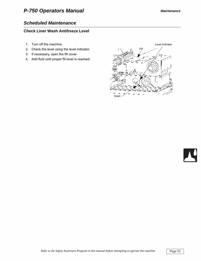
. Turn off the machine.
. Remove the oil level plug.
. Inspect the oil. If contaminated, drain, flush and change immediately.
. Check the oil level on the level indicator. Add oil until proper fill level is reach.
FillLevel Indicator
Drain
DS
CF6
109
Page 53Refer to the Safety Awareness Program in this manual before attempting to operate this machine

P-750 Operators Manual
Page
Maintenance
Che
1. 2.
3.
4.
5.
6.
Scheduled Maintenanceck Pump Chainbox Oil Level
Turn off the machine.Check the oil level using the transparent gauge mounted on the side of the chainbox.Inspect the oil. If contaminated or milky, flush and change immediately.The oil level should be to the midpoint of the gauge. Remove the fill cover (drawing above) or the vent plug (drawing below). Add oil as necessary.
Level Indicator
Fill
Drain
75m
p101
5B-c
hain
box
Level Indicator
Fill
Drain
54 Refer to the Safety Awareness Program in this manual before attempting to operate this machine
P-750 Operators Manual
S
Maintenance
Ch
1234
cheduled Maintenanceeck Liner Wash Antifreeze Level
. Turn off the machine.
. Check the level using the level indicator.
. If necessary, open the fill cover.
. Add fluid until proper fill level is reached.
Fill
Level Indicator
Drain
75m
p101
5B-li
ner w
ash
Page 55Refer to the Safety Awareness Program in this manual before attempting to operate this machine

P-750 Operators Manual
Page
Maintenance
Gen
fluid
Scheduled Maintenanceeral Inspections
Inspect the machine for leaks of gear oil and hydraulic oil. Leaks should be repaired. Allowing oil or other s to leak into the environment is unlawful in most locations. Observe the following:
• Power end seal leakage; Observe while the pump is operating at normal temperature. If repairs are required, turn the machine off and follow proper lockout and tagout procedures.
• Pony rod gland seals; Although a small amount of dripping from the seals is normal, replace the seals when excessive leakage occurs.
• Liquid end seal leakage; Observe while the pump is operating at normal pressure. If repairs are
Use of equipment with damaged hoses, fittings, loose or missing fasteners may result in damage to the machine, personal injury or death. Inspect the machine regularly. Replace or repair damaged or missing components promptly.
Hydraulic fluid under pressure can cause serious personal injury and death if it penetrates the skin. Stay away from the jet.
• Use a piece of cardboard or wood to check for pressurized leaks to prevent fluid penetrating the skin.
• Seek immediate medical attention if hydraulic fluid has penetrated the skin even if the injury seems minor. Prompt medical treatment by a physician familiar with this injury is essential.
Hot surfaces can cause burns. Do not touch until cool.
56 Refer to the Safety Awareness Program in this manual before attempting to operate this machine
required, turn the machine off and follow proper lockout and tagout procedures.• Liquid end packing; A slight leak is normal and extends packing life. If excessive leaking occurs with
adjustable packing, try adjusting the Stuffing box Nut. If excessive leakage persists, replace the pack-ing.
• Cover caps; If they are leaking, ensure the Cap/Cap Fasteners are in good condition and properly torqued. If properly torqued and still leaking, replace the Cap seals.
• Check that power frame plunger hold drains and piping are clear to evacuate any product or oil leak-age.
• Visually inspect plungers. Worn or damaged plungers will cause premature packing failure/wear and an increase in NPSHR (net positive suction head required). Look for excessive grooving, pits or flaking in the plunger coating.
Visually inspect all hoses, fittings and pipes. Replace parts that are damaged.

P-750 Operators Manual
S
Maintenance
Re
En
ce
bavo
to gre
IM•
•
cheduled Maintenance
Ensure drive coupling is secure and properly adjusted.
Check all major fasteners, such as hose clamps, stakedown, tie downs, etc. Tighten all loose fasteners. place any that are missing or damaged. Check the control cable connections and ensure they are tight.
gine: Check Battery and Battery Fluid Levels
Check the level of the electrolyte in the batteries. Add distilled water until level is at the split ring of each
BATTERY ACID CAN CAUSE SEVERE BURNS. Batteries contain sulfuric acid. Avoid contact with skin, eyes or clothing. Wear eye protection and gloves when working with batteries.
ANTIDOTE:• EXTERNAL: flush with water.• INTERNAL: drink large quantities of water or milk. Follow with milk of magnesia,
beaten egg or vegetable oil. Call Poison control and a physician immediately.• EYES: flush with water for 15 minutes and get prompt medical attention.
All exposed metal parts on a storage battery are “live”. Laying a metal object across the terminals may cause a spark, short circuit or explosion. Personal injury or damage to the equipment may result. Never lay a metal object across the battery terminals.
PORTANT: When disconnecting battery terminals, remove the Negative (-) GROUND cable first; then remove the
Positive (+). When connecting the cables, connect the Positive (+) first, then connect the Negative (-) GROUND cable last.
To prevent damage to the battery, DO NOT over tighten the battery hold down.
Page 57Refer to the Safety Awareness Program in this manual before attempting to operate this machine
ll opening if the level is too low.
Check the battery cables and verify that there are no abrasions or indentations; if necessary, replace the ttery cables. Check that the battery terminals are not corroded. Clean and replace them if necessary. The ltage of the battery is 12 volts.
Clean corrosion off battery terminals. A paste made of sodium bicarbonate and water is normally enough clean terminals and battery box. After cleaning, rinse thoroughly with clean water. Coat the terminals with ase in order to prevent future corrosion.

P-750 Operators Manual
Page
Maintenance
50
Eng
ter, c
and
Che
NOsed
1. 2.
3.
4.
Scheduled Maintenance
Hour Inspection and Maintenance
Perform 10 Hour Inspection and Maintenance items, plus:
ine: Remove Water from Fuel Filter
Open the water drain at the bottom of the fuel filter (see photo below).
Close the drain after all water has been removed. If there is an excess of water being drained from the fil-heck for water in the fuel tank.
If there is water in the fuel tank, remove the drain plug from the bottom of the fuel tank and allow water sediment to drain. Replace and tighten the plug after draining is complete.
ck Transmission Fluid Level
TE: Always drain water and sediment into a container and dispose of properly. Never allow water and iment to drain onto the ground.
Turn off the machine.Check the fluid level using the level/fill port on the side of the transmission.The fluid should be level with the bottom of the port.Add fluid if necessary.
Drain for water separator bowl for engines so equipped
p101
5B-tr
ansm
issi
on
58 Refer to the Safety Awareness Program in this manual before attempting to operate this machine
Level & Fill
75m

P-750 Operators Manual
S
Maintenance
O
rem
entheberunis
cheduled Maintenancether Items
Lubricate the drive shaft between the engine and the pump. Access the drive shaft grease fittings by oving the drive shaft guard.
Tighten the pump flange bolts.
Ventilate the surge chamber (1) on the mud pump discharge dampener. The discharge dampener damp-s surges of the mud pump. The standard surge chamber is an air chamber where the mud compresses air to dampen movement of the discharge hose. The mud gradually absorbs the air in the surge cham-
r. Remove the plug on top (2) of the surge chamber to allow air into the chamber when the pump is not ning. Reinstall the plug before resuming operations. An optional nitrogen filled, bladdered surge chamber
available.
1
2
75m
p101
5B-p
ress
ure
relie
f
Page 59Refer to the Safety Awareness Program in this manual before attempting to operate this machine

P-750 Operators Manual
Page
Maintenance
500
Cha
1. 2. 3.
4. 5.
6. 7. 8. 9. 10.
Eng
worn
Tes
corroaccu
IMPize
Scheduled Maintenance
Hour Inspection and Maintenance
Perform 10 and 50 Hour Inspection and Maintenance items, plus:
nge the Engine Oil and Filter
Engine oil should be warm to assist in draining. To change the engine oil and filter:
Wipe the area around the oil filler cap with a clean rag. Remove the oil filler cap.Place a container under the oil pan drain plug. Remove the oil pan drain plug and drain the engine oil.Using a filter wrench, remove and discard the old oil filter element and o-rings. Clean the area with a clean rag.Apply a thin coat of oil to the o-ring of the new filter element. Install the new filter element.Hand tighten filter making contact with base. Continue to tighten 3/4 turn. DO NOT use a filter wrench to tighten the filter. Damage to the filter may result.Install and tighten the drain plug.Add correct type and amount of engine oil via the filler tube. Replace the oil filler cap.Start the engine and check for leaks.Turn off engine and remove the key. After a few minutes, use the dipstick and recheck the oil level. Repeat the leak check.
ine Belts
Check that belts have the correct tension. If they have loosened, adjust them. Replace belts if they are over the limits. Follow instructions in Attachment 1, you diesel engine manual.
Hot surfaces can cause burns. Do not touch until cool.
60 Refer to the Safety Awareness Program in this manual before attempting to operate this machine
t Radiator Coolant
pH should be maintained between 9.5 and 10.0. Coolant with pH below 8.3 is not acceptable due to its sive nature. When coolant pH drops below 9.0, flush the cooling system and refill with fresh coolant. For rate pH readings, the coolant should be below 122°F (50°C).
ORTANT: Water quality is important to the performance of the cooling system. Use distilled, deion-d or demineralized water when mixing with coolant concentrate.

P-750 Operators Manual
S
Maintenance
Cl
the
ca
1. 2. 3. 4.
5. 6.
O
cheduled Maintenanceean/Replace Air Filter Elements
The air filter assembly should be cleaned and the air filter replaced every 250 hours. In dusty conditions, filter element should be checked and cleaned more frequently.
The air filter assembly includes the housing, cover, external element, internal element and a service indi-tor. The housing is shown in the photograph below.
To check and clean the air filter system:
Release the cover latches and remove the housing cover.Remove the outer element.Remove the inner element and wipe out any dust which has collected on the inside of the housing.Replace the inner element. The closed end of the element should be toward the housing cover. Be care-ful that the inner element is installed correctly.Replace the outer elementReplace the housing cover and secure the cover latches.
ther Items
Tighten drive shaft fasteners.
Page 61Refer to the Safety Awareness Program in this manual before attempting to operate this machine

P-750 Operators Manual
Page
Maintenance
100
Cha
1. 2. P3. 4. 5. 6.
co
7.
Rem
Eng
1. 2. 3.
IMP• N
dd
• Ae
Scheduled Maintenance
0 Hour Inspection and Maintenance
Perform 10, 50 and 500 Hour Inspection and Maintenance items, plus:
nge the Fuel Filter Elements
Turn off the engine and remove the key.lace a container under the fuel filters to avoid any spills.
Clean the filter head and the outside of the fuel filters.Turn the filters counterclockwise and remove from the filter head. Discard the old filter elements.Apply a thin layer of clean oil to the gasket of the new filter elements.Install the filter elements by hand turning clockwise. Hand tighten 1/2 to 3/4 turn after the elements make ontact with the filter head. DO NOT use a filter wrench to install filters. Damage to the filter gasket may ccur.
Remove air from the fuel system as explained below.
ove Air from the Fuel System
Air must be removed from the fuel system when any of the following occur:
• The engine is run until the fuel tank is empty.• The fuel filter elements are replaced.• The fuel system is serviced.• The engine has been in storage for a long time.
*Refer to Attachment 1: “Diesel Engine Manual” for instructions on removing air from the fuel system.
ine: Clean the Cooling System and Replace Coolant
Hot coolant can spray out and cause serious injury. Do not remove radiator cap while the engine is hot. Wait for the engine to cool.
• Slowly open the radiator cap and allow pressure to escape slowly.• Always wear face protection (face shield or goggles) when cleaning radiator fins
with compressed air or pressure washer.
62 Refer to the Safety Awareness Program in this manual before attempting to operate this machine
When the system is cool, turn the radiator cap to the first notch. Wait until all pressure is released.Slowly remove the radiator cap. Scalding can result from fast removal of radiator cap.Place a suitable container under the radiator drain tube (adjacent to the petcock shown below).
ORTANT:EVER put cold coolant in a hot engine. The engine block or cylinder heads can crack because of the ifference in temperature between the metal and the coolant. Make sure the engine block and radiator rain valves are closed.lways use a container and dispose of waste coolant properly. Make sure the container will have nough capacity to avoid spillage. Never allow coolant to drain onto the ground.

P-750 Operators Manual
S
Maintenance
4. 5.
6. 7.
8.
9. 1011
Ch
12
3
4
56
cheduled Maintenance
Rotate the petcock handle counterclockwise to open the drain.When the engine and radiator are cool and the system is drained, run fresh, clean water through the sys-tem. This will flush out any particles. Allow water to drain from the system before refilling.Close the drain.Fill the radiator with a 50/50 mixture of clean water and ethylene glycol. Slowly add the coolant solution until the level comes up to the filler port neck.With the radiator is full, start the engine and run at low idle for approximately 5 minutes. Coolant level will drop.Turn OFF the engine and remove the key. Fill radiator with coolant to filler port neck.
. Replace the radiator cap.. Fill the coolant reservoir to the proper level.
ange Pump Crankcase Oil
. Turn off the machine.
. Using diesel fuel or solvent, flush and clean the entire crankcase area.
. Place a suitable container under the crankcase drain. Open the drain and collect the oil. Dispose of properly.
FillLevel Indicator
Page 63Refer to the Safety Awareness Program in this manual before attempting to operate this machine
. If contaminants are observed in the oil, determine the cause and repair before using the pump.
. Close the drain.
. Refill with fresh oil. Close the fill port.
Drain
DS
CF6
109
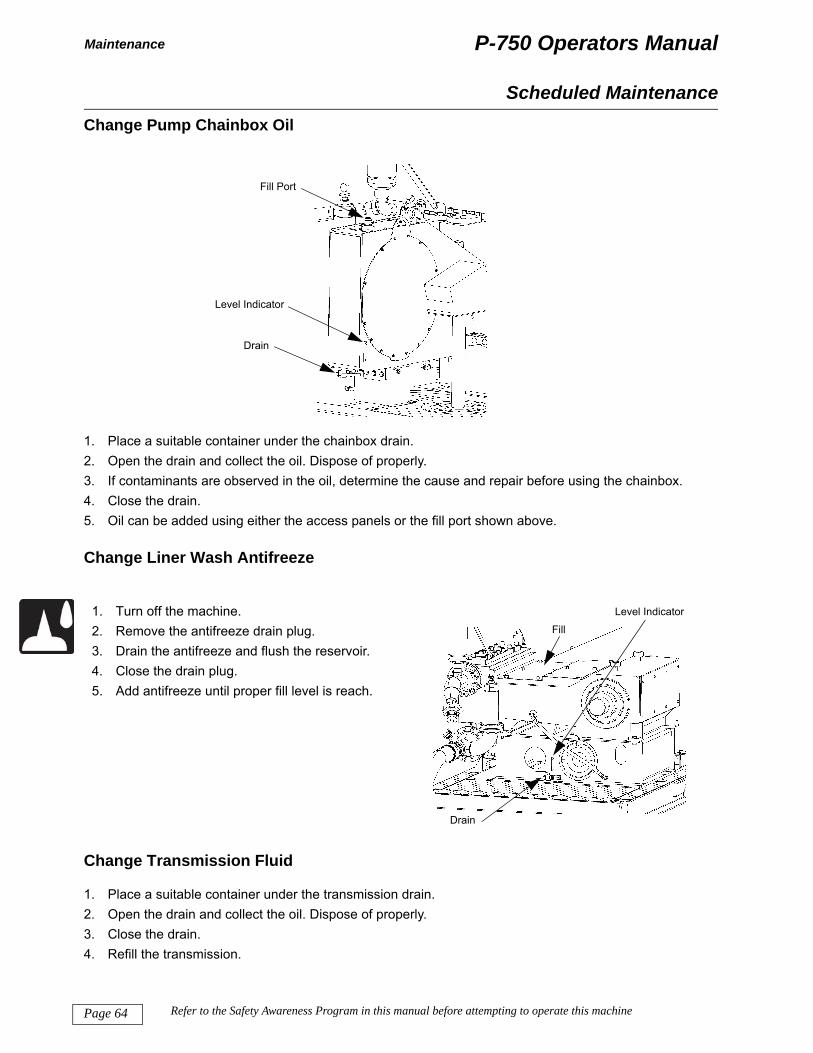
P-750 Operators Manual
Page
Maintenance
Cha
1. 2. 3. 4. 5. O
Cha
Cha
1. 2. 3. 4. R
1. 2. 3. 4. 5.
Scheduled Maintenancenge Pump Chainbox Oil
Place a suitable container under the chainbox drain.Open the drain and collect the oil. Dispose of properly.If contaminants are observed in the oil, determine the cause and repair before using the chainbox.Close the drain.
il can be added using either the access panels or the fill port shown above.
nge Liner Wash Antifreeze
Turn off the machine.Remove the antifreeze drain plug.Drain the antifreeze and flush the reservoir.Close the drain plug.Add antifreeze until proper fill level is reach.
Level Indicator
Fill Port
Drain
Fill
Level Indicator
5mp1
015B
-line
r was
h
64 Refer to the Safety Awareness Program in this manual before attempting to operate this machine
nge Transmission Fluid
Place a suitable container under the transmission drain.Open the drain and collect the oil. Dispose of properly.Close the drain.
efill the transmission.
Drain
7

P-750 Operators Manual Specifications
Specifications
SpecificationsMachine Dimensions / Weight
Length: 25 feet 6 inches (7.8 m)Width: 8 feet (2.5 m)Height: 10 feet 3 inches (3.12 m)Estimated Weight: 39,000 pounds (17,690 kg)
Power Train
Engine: Caterpillar C-18 Diesel (Tier depends on place of purchase)Rating: 600 HP (447 kW)Fuel Capacity: 300 gallons (1,136 liters)Transmission: Eaton RTLO-22918B, 10-speedBattery: (2) DEKA 908 DMF, 12 volt, 1450 CCA
Pump
Pump Design: Quintiplex, piston and linerRated Capacity: *750 U.S. Gallons (2,839 liters)/minBore X Stroke: 5.5 X 7.87 inches (139.7 X 200 mm)Maximum Pressure: 1500 psi (103 bar)(* Note: Pump capacity will vary depending on the overall mud weight, drilling fluid mixture/content, and
the working elevation)
Controls
Remote Control: Mud Pump Throttle, Mud Pump Start/Stop, Clutch Actuator, HornRemote Instruments: Digital Mud Flow Meter (gallons per minute / liters per minute)
Accessories
Pulsation Dampeners on inlet and dischargeTwo 25 foot (7.6 m) suction hoses with 6 inch (152 mm) kamlock fittings33 U.S. Gallons (125 liters) per minute liner wash system with supply tank
Page 65Refer to the Safety Awareness Program in this manual before attempting to operate this machine
Two, 24 volt work lights

P-750 Operators ManualNotes
Notes
NOTES:
Page 66 Refer to the Safety Awareness Program in this manual before attempting to operate this machine

P-750 Operators Manual Appendix
Appendix
Appendix
The appendix contains information that we believe the operator of the P-750 will find useful to have available for reference during the operation of the P-750. The information is placed in the appendix because it is of general interest or it supplements the information in the body of the manual.
Page 67Refer to the Safety Awareness Program in this manual before attempting to operate this machine

P-750 Operators ManualNotes
Notes
NOTES:
Page 68 Refer to the Safety Awareness Program in this manual before attempting to operate this machine

P-750 Operators Manual
Page 69
Appendix A
Refer to the Safety Awareness Program in this manual before attempting to operate this machine
Appendix A: List of Attachments
Appendix AAttachment 1: Diesel Engine Manual
Attachment 2: Murphy Power System Users Guide (for machines from P750100112)
Attachment 3: Murphy Troubleshooting (for machines from P750100112)
Attachment 4: Murphy Error Messages (for machines from P750100112)
Attachment 5: American Augers Lubrication Guide (current revisions)

Page 70
P-750 Operators ManualDeclaration of Conformity
Refer to the Safety Awareness Program in this manual before attempting to operate this machine
Sample Declaration of Conformity
Mud PumpP-750

P-750 Operators Manual Limited Warranty
Limited Warranty
Limited Warranty
This warranty is extended by American Augers, Incorporated in respect of equipment & products sold. American Augers warrants to the initial purchaser that this Equipment will be free of defects in material and/or workmanship for a period of 365 days after the fac-tory shipment date to the initial purchaser, or 1000 hours of operation, whichever occurs first. Once the equipment is placed into service as a retail sale, rental or lease, a properly completed Warranty Registration Certificate must be submitted to American Augers to start and validate warranty coverage.
• The Limited Warranty does not include (1) batteries, lamp bulbs, fuses, various types of gaskets, and packing, filter elements, oil lubricants, fluids, track chain, track drive sprockets, Drill Pipe, Auger sections, die holders, wrench wear parts, guide bush-ings, shaft seals, mud swivel assemblies, valves, piston liners, centrifugal pumps, shaker screens, and other normal wearing or aging parts, (2) engines, and (3) transmissions not manufactured by American Augers, (4) down hole tools & accessories. American Augers extends to the initial purchaser the benefits of any warranty (if any) of the manufacturers or suppliers of any of the excluded items.
• Claims for defects in material and workmanship shall be made in writing by the initial purchaser to American Augers within ten days of defect discovery. American Augers reserves the right to send a service representative, contract an authorized repre-sentative, or request that the equipment is returned to the factory for product inspections. Failure on the behalf of the pur-chaser to permit such above action can cause a voiding of warranty coverage.
• Within the warranty period, American Augers will repair or replace, at its option, free of charge any portion of parts of the new Equipment, which are found by American Augers to be defective in material or workmanship. Replacement or repaired parts provided under the terms hereof are guaranteed in like fashion for the remainder of the warranty period. Any parts replaced under the terms of this warranty become the property of American Augers and upon written request, must be returned, trans-portation prepaid, to American Augers.
• In no event shall American Auger’s liability exceed the purchase price of the Equipment. American Augers reserves the right to fully satisfy its warranty obligation by refunding to the Buyer the full purchase price of the Equipment upon the return of the Equipment by the Buyer, transportation prepaid, to American Augers.
• This warranty applies only if the alleged defective Equipment has been properly maintained and operated as specified by American Augers. This warranty will not apply if the alleged defect is attributable to an unauthorized modification or service repair made, a component part installed, improper equipment storage, neglect or abuse of the equipment on the behalf of the purchaser or their representatives, improper product operation or use of the product exceeding the design limitations, or an attachment supplied, by a party other than American Augers or its subsidiaries, or the authorized representative of any of the forgoing.
• If any tests are conducted to ascertain or demonstrate defects in material or workmanship, such test shall be conducted after reasonable notice to American Augers and upon conditions mutually agreed upon in advance of the test, and American Augers may be represented at any test that shall be made. American Augers, at its option may charge the Customer for any tests performed by American Augers at the request of the Customer in respect to the merchandise sold hereunder.
• The remedies in this warranty shall be exclusive and sole remedies of the Buyer. There are no other Warranties, expressed or implied, of any kind, including but without limitation, any warranty that the Equipment is of merchantable quality or that the Equipment is fit for any particular purpose. American Augers will have no monetary liability whatsoever for any damage, loss costs, or expense (whether general, special, incidental, or consequential) suffered by the Buyer as a result of or connection with the Equipment. In no event shall American Augers be liable for incidental or consequential damages including, but not limited to, freight charges, transportation charges, downtime, or other parts incidental to the removal and replacement of parts repaired or replaced under this warranty.
• American Augers reserves the right to modify, alter, and improve any product or pats without incurring any obligation to replace any product or parts previously sold with such modified, altered or improved product or parts.
• No person is authorized to alter or extend this warranty unless made in writing and signed by an officer of American Augers.
Page 71Refer to the Safety Awareness Program in this manual before attempting to operate this machine
• Used products and equipment delivered by American Augers or picked up by American Augers are sold without conditions or warranties, express or implied, “as is, where is”, unless there is a clear agreement with the Customer in writing to the contrary. The Customer agrees to inspect and all such equipment before purchase is completed and to accept same with out any war-ranty of merchantability or fitness for a particular purpose.
By acceptance hereof, the Customer covenants and agrees that in the event any products purchased hereunder are resold either in their original form or as a component of another system, the LIMITED WARRANTIES provision set forth above will be included in all sales documents by which the Customer resells any such products. In all such cases, the sales documents by which a purchaser from the Customer purchases and accepts delivery of the products sold here under will include from such LIMITED WARRANTIES and prior to any such sale or delivery and authorized representative of the subsequent purchaser will be made aware of the limitations on the warranty of American Augers or other manufacturer of the products and that the disclaimers of American Augers apply to the resale of such products. The Customer agrees to indemnify and hold harmless American Augers from any such loss, claim or damage. Including attorney’s fees and expenses resulting from a breach of the foregoing covenant.

American Augers, Inc.135 US Route 42
P.O. Box 814West Salem, Ohio 44287
www.americanaugers.com
Always include machine serial number when ordering partsDue to our continuing product improvement, machine specifications are subject to change without notice.
Original InstructionsManual Part Number 75MP10000Released May 2012 Revision 01