oxyfuel conversion of heaters and boilers for co 2 capture · - 1 - second national conference on...
TRANSCRIPT

- 1 -
Second National Conference on Carbon Sequestration, May 5th – 8th 2003, Washington, DC
Oxyfuel Conversion of Heaters and Boilers for CO2 Capture
Michael B Wilkinson ([email protected]; +44 1932 763369) Mark Simmonds ([email protected]; +44 1932 775 641)
BP Chertsey Road, Sunbury-on-Thames, Middlesex, TW16 7LN, UK
Rodney J Allam ([email protected]; +44 1932 249935)
Vince White ([email protected]; +44 1932 249948) Air Products PLC
Hersham Place, Molesey Road, Walton-on-Thames, Surrey, KT12 4RZ, UK
Abstract The CO2 Capture Project is a major joint energy initiative by the energy industry to address problems of CO2 emission that have the potential to cause climate change. Its objective is to provide very significant cost reduction in CO2 removal and storage compared to existing technologies by considering various technology options applied at different real locations. This feasibility study involves the potential application of Oxyfuel technology on a refinery-wide basis at the BP Grangemouth unit in Scotland. Previous studies in Oxyfuel technology have considered application for retrofit on a power station boiler and refinery process heaters. A total of seven boilers and 13 process heaters of various types burning a mixture of refinery fuel gas and fuel oil form the basis of this study. This work considers the issues involved in locating two world scale air separation plants totalling up to 7400 tonne/day of oxygen plus a CO2 compression and purification system on a congested site, in addition to the issues of distributing the oxygen around the site and collecting the CO2 rich effluent from the combustion processes for purification and final compression.
1. Introduction
1.1 The CCP
The CO2 capture project (CCP) is a major joint energy industry effort to respond to concerns which exist around climate change and CO2 concentrations in the atmosphere. The CCP involves the following participant companies: BP (Co-ordination), Chevron Texaco, En Cana, Eni, Norsk Hydro, Shell, Statoil and Suncor. Funding comes from, not only the participating companies, but also from the Department of Energy in the U.S., from Norway and from the European Union. The function of the CCP is to achieve major reductions in the cost of CO2 capture and storage compared to existing technologies. In addition, there is work to show that geological CO2 storage is safe, measurable and verifiable.
- 2 -
The mechanism of the project has been to commission studies on various technology options applied to real locations where major CO2 emissions occur. The objective is to reach proof of concept stage by the end of 2003 and have a demonstration in operation by 2010.
1.2 Technology Options
There are 3 main technology options for the removal of CO2 from fossil fuel combustion processes.
1. The end of pipe solution involving using an absorption or adsorption process for CO2 removal from the vent gas. The base case for these studies is the use of an amine chemical absorption system.
2. Precombustion decarbonisation involves the conversion of the fossil fuel to hydrogen with all carbon converted to CO2, which can be removed from the pressurised hydrogen fuel gas stream prior to its use as fuel for power production in a gas turbine combined cycle or a fuel cell.
3. Oxyfuel, which involves the substitution of air in the fossil fuel burner with pure oxygen and recycled flue gas, giving a stream which, after cooling and condensation of water, consists of a high concentration of carbon dioxide.
The produced CO2 following compression and delivery by pipeline can be disposed of in geological formations as follows:
1. Injection into oil formation for enhanced recovery. 2. Storage in depleted oil and gas reservoirs. 3. Storage in saline aquifers
1.3 The Study of The Oxyfuel Option
This paper presents preliminary results on a feasibility study at present being carried out on the oxyfuel conversion of steam raising boilers and process heaters in the Grangemouth refinery of BP which is located in Scotland near Edinburgh. The study is being carried out by Air Products as technology provider to the CCP with the assistance of Mitsui-Babcock (boiler conversions) and Foster Wheeler (process heater conversions).
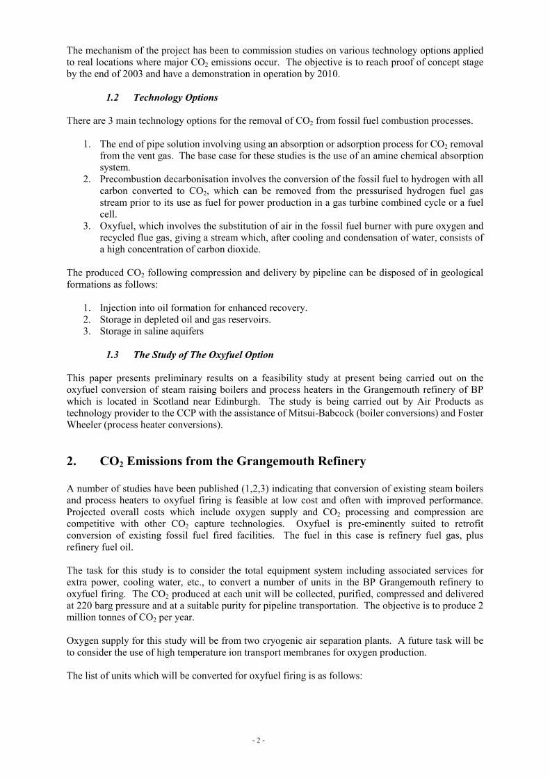
2. CO2 Emissions from the Grangemouth Refinery A number of studies have been published (1,2,3) indicating that conversion of existing steam boilers and process heaters to oxyfuel firing is feasible at low cost and often with improved performance. Projected overall costs which include oxygen supply and CO2 processing and compression are competitive with other CO2 capture technologies. Oxyfuel is pre-eminently suited to retrofit conversion of existing fossil fuel fired facilities. The fuel in this case is refinery fuel gas, plus refinery fuel oil. The task for this study is to consider the total equipment system including associated services for extra power, cooling water, etc., to convert a number of units in the BP Grangemouth refinery to oxyfuel firing. The CO2 produced at each unit will be collected, purified, compressed and delivered at 220 barg pressure and at a suitable purity for pipeline transportation. The objective is to produce 2 million tonnes of CO2 per year. Oxygen supply for this study will be from two cryogenic air separation plants. A future task will be to consider the use of high temperature ion transport membranes for oxygen production. The list of units which will be converted for oxyfuel firing is as follows:
- 3 -
Five Simon Carves boilers each supplying 300,000 lb/hr steam. Typical fuel mix 40% gas, 60% oil by weight. These are linked to two stacks. Two Babcock steam boilers each supplying 500,000 lb/hr steam. Average fuel mix 40% gas 60% oil by weight. These two boilers are linked to a single stack. The steam conditions for all these boilers is 127.6 barg, 518°C. There are, in addition, a total of 12 process heaters of various types which have been specified for oxyfuel conversion – box, cabin or vertical cylindrical. Duties vary from 10.3MW to 112.3MW. Fuel is either gas alone or a combination of gas and fuel oil. In addition, there is a hydrogen producing steam/natural gas reformer furnace fired by fuel gas. Summary details of the heaters and boilers considered in this study are given in Table 1. This gives the CO2 emissions with air firing, the CO2 delivered to the pipeline when operating in the oxyfuel mode and the total oxygen consumptions. It is clear from these results that one of the benefits of oxyfuel firing is a reduction in fuel required, in this case 6% reduction. This is the reason that the total CO2 captured is below the 2.0 million tonne per year target.
Air Firing Oxyfuel Firing
Total Fuel Consumption
kg/hr
Total CO2 Emitted kg/hr
Total Fuel Consumption
kg/hr
Total O2 Consumption
kg/hr
Total CO2 Captured
kg/hr Boilers B1 - B7 54,809 164,270 52,519 179,835 146,424 Heaters H1 - H12 26,510 73,828 24,302 90,339 63,166 Reformer H13 3,600 9,791 2,813 10,494 7,135 Totals 6736 tonne/day O2 1.90 million tonne/year CO2
Table 1: Grangemouth Heaters and Boilers

- 4 -
3. Oxyfuel Boiler Conversion A detailed analysis of the conversion of one of the Babcock boilers at BP Grangemouth has been given in a previous paper (2,3). Figure 1 shows diagrammatically the way in which the boiler conversion is carried out and the typical performance characteristics of the oxyfuel system.
Air FD Fan Steam Heater Boiler
Steam
ID Fan
Stack
Fuel
64.82 kg/s10°C
64.82 kg/s15°C
64.82 kg/s69°C
4.35 kg/s
63.0 kg/s
74.51 kg/s231°C
1.5 %w/wO2
9.5 %w/wH2O
71.6 %w/wN2
17.4 %w/wCO2
1.5 %w/wO2
9.5 %w/wH2O
71.6 %w/wN2
17.4 %w/wCO2
Air Infiltration
a) Boiler with air firing
Air FD Fan Steam Heater
O2 from ASU
Boiler
Steam
ID Fan
Stack
Air Infiltration
Local CO2 Drying and Compression
FGR Fan
Fuel4.12 kg/s
63.0 kg/s
41.06 kg/s220°C9.2 %w/wInerts
1.6 %w/wO2
29.6 %w/wH2O
59.6 %w/wCO2
9.2 %w/wInerts
1.6 %w/wO2
29.6 %w/wH2O
59.6 %w/wCO2
20.50 kg/s15.08 kg/s
Not required for Oxyfuel firing but retained for air firing backup
b) Boiler converted to Oxyfuel firing
Figure 1: Comparison of air and oxyfuel firing boiler New equipment will include a recycle flue gas line and blower, 100% shutoff stack damper, oxygen injection and mixing system and possible burner modifications. The revised control system will allow air firing to be re-established in the event of an oxygen supply failure without tripping the boiler. This can be achieved with a liquid oxygen (LOX) and gaseous oxygen (GOX) instant demand back-up system which maintains oxygen supply pressure while the air fans are started. A critical parameter, which must be established by careful performance analysis on an existing boiler is the amount of air in-leakage and the possibility of reducing this to a minimum by repairs. The inert nitrogen and argon can be a problem, particularly if the CO2 is to be used for enhanced oil recovery. The limit for these studies is 3%. Excess O2 plus SO2, NOX, CO or hydrocarbons are not considered to be a problem for this application. If the boiler air in-leakage is low, then an oxygen purity of 99.5% would be specified to keep (N2+Ar) below 3%. If the air in-leakage is higher then 95% to 97% oxygen purity would be specified and an inerts removal plant would be used to reach the required

- 5 -
specification. In all cases considered at BP, tests and engineering analysis have shown that the air in-leakage achievable means an oxygen purity specification of 95% and the provision of an inerts removal plant.
4. Oxyfuel Heater Conversion The conversion of process heaters to oxyfuel firing requires a similar modification to the system as that described for the boiler conversion (1). A key criteria for the process heaters is to ensure that the peak heat flux to the tube surfaces is not increased. This is normally fixed by stability of process fluids or tube metallurgy. This constraint is maintained for the higher emissivity CO2 rich gas in the furnace by increasing the recycle to oxygen feed ratio to operate at below 21% oxygen concentration thus limiting flame temperature. The same overall duty is maintained in each case and also the same balance of radiant and convection section duties. The firing rate is reduced because of the lower heat loss in the smaller nett flue gas flow. The case of the steam/natural gas reformer furnace is interesting as this only requires radiant heat and thus the higher emissivity furnace gas allows the firing rate to be reduced by 15% and still maintain the same radiant heat flux. The lower firing rate reduces the excess steam production in the convection section.
5. Flue Gas Inerts Separation and CO2 Compression Due to the widely scattered location of the boilers and heaters in the refinery, it is necessary to collect the CO2 rich flue gas and pipe it to a central location for final purification and compression. The flue gas product from each oxyfuel unit varies in temperature from 180°C to 398°C and contains about 30% water vapour. The ambient pressure flue gas is piped a short distance to a local collection point where it is cooled in a venturi water scrubber followed by a direct contact packed tower. The water vapour is condensed and the flue gas is compressed in a centrifugal integrally geared compressor to 32 bar. The gas is then passed into a dual bed desiccant drier to reduce the water content to a dewpoint below -60°C. A PFD for the largest local CO2 dryer, in the boiler area, is shown in Figure 2a alongside an isometric view of the equipment, Figure 2b. The dry CO2 can now be piped in carbon steel lines to the central purification and final compression point.

- 6 -
Cooling water return2704 tonne/hr44°C
Cooling water2617 tonne/hr 24°C
Boiler feed water12.2 tonne/hr
Direct Contact Cooler
Compression14.5 MW
Dryers
To central purification system
Flue gas (collected from local heaters or boilers)
kmol/hr 8,777CO2 40.77 mol%O2 1.67 mol%Ar 2.10 mol%N2 8.08 mol%
H2O 47.28 mol%SO2 0.08 mol%
Total, kmol/hr 4,577T, °C 30.00P, bara 32.06
77.19 mol%3.21 mol%4.03 mol%
15.49 mol%0.00 mol%0.08 mol%
T, °C 283 CO2O2ArN2
H2OSO2
Water knockout2.4 tonne/hr
a) PFD of local CO2 treatment area for boilers
b) Isometric view of area
Figure 2: PFD and Isometric view of CO2 treatment area for boilers

- 7 -
Figure 3: Central CO2 purification system
Dry CO2 from local drying and compression areas
CO2 product for sequestration
0.1 mol%SO2
34.1 mol%O2
4.5 mol%Ar
14.3 mol%N2
77.0 mol%CO2
30 baraP
0.1 mol%SO2
34.1 mol%O2
4.5 mol%Ar
14.3 mol%N2
77.0 mol%CO2
30 baraP
0.1mol%SO2
0.7 mol%O2
1.1 mol%Ar
1.9 mol%N2
96.2 mol%CO2
221 baraP
0.1mol%SO2
0.7 mol%O2
1.1 mol%Ar
1.9 mol%N2
96.2 mol%CO2
221 baraP
0.0 mol%SO2
13.5 mol%O2
13.6 mol%Ar
47.8 mol%N2
25.1 mol%CO2
0.0 mol%SO2
13.5 mol%O2
13.6 mol%Ar
47.8 mol%N2
25.1 mol%CO2-55.8 °C
9.8 bara
-55.8 °C
9.8 bara
-30.9 °C
19.6 bara
-30.9 °C
19.6 bara
Flue Gas Expander
Flue Gas Vent
Flue Gas Heater
Warm Exchanger
Cold Exchanger
CO2Compressor
CO2 Compressor

- 8 -
Figure 3 shows an inerts gas removal plant using CO2 refrigeration, which separates the inert gases from the CO2 at a temperature of about –55°C which is close to the CO2 freezing temperature. At this point the CO2 partial pressure in the vapour phase has been reduced to about 7 bar. The refrigeration is obtained by evaporating two streams of CO2 at pressure levels of typically around 10 bar and 20 bar and recycling the CO2 gas in the main CO2 compressor. The separated inert gas at 29 bar can be heated and passed through a power recovery turbine. It is possible to reach a CO2 purity in excess of 96% using this method at inlet CO2 concentrations as low as 80% with a CO2 recovery of better than 90%.

- 9 -
Waste
Gaseous O2
N2
Air
cw
cw out
Low Pressure Column
High Pressure Column
Integrated Reboiler/Condenser
Liquid O2
Subcooler
H2O and CO2removal
Main Air Compressor
cw
Booster Compressor
Expander
Common Shaft
5.52 bara
Direct Contact After Cooler
Chill Tower
-179.4°C4.46 bara
-171.4°C
-193.2°C1.33 bara
Figure 4: Cryogenic Air Separation Plant
- 10 -
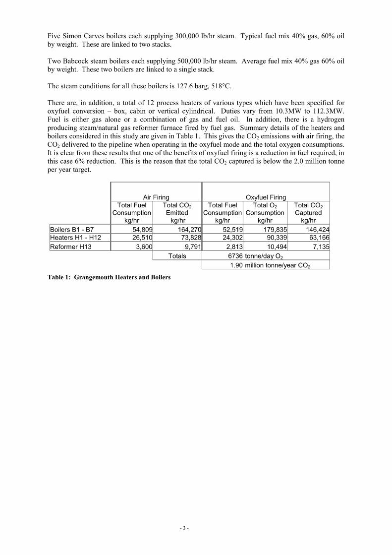
6. Cryogenic Air Separation Plant The maximum total oxygen demand of 7400 tonne/day which includes a 10% flow margin is provided by two cryogenic air separation plants (ASUs) with single air compressors, Figure 4, provided as two trains of 3700 tonne/day, which is close to the current largest plant size of 3500 tonne/day. The oxygen is delivered at 95% purity 1.7 bar abs into a pipeline system which runs to each of the oxyfuel use points. The plants utilise a cryogenic distillation system for air separation based on the use of an upper low pressure column in which the air is separated into a gaseous nitrogen stream leaving the top and a liquid oxygen stream leaving the base. The lower column is linked to the upper column through a reboiler-condenser in which N2 separated from the air feed is condensed against boiling oxygen. The liquid nitrogen produced provides reflux for the upper and lower columns. The reboiler conditions impose a pressure on the air feed of 5.5 bar abs. The liquid oxygen is vaporised and the gaseous nitrogen and oxygen products are warmed to atmospheric temperature against cooling air, part of which has been further compressed to assist in the vaporisation of the oxygen. The heat exchange system uses aluminium plate-fin heat exchangers. The columns use a structured packing for separation of components. Plant refrigeration is provided by an air expansion turbine discharging into the lower pressure column. Oxygen pressurisation is achieved using hydrostatic head, no liquid oxygen pumps or oxygen gas compressors are required. The air leaving the compressors is passed through a set of two switching adsorber vessels which remove water, CO2, N2O and hydrocarbon impurities which would contaminate the cryogenic equipment. Each plant is provided with a single air compressor. These can be designed either as intercooled machines with an aftercooler, in which the heat of compression is rejected to cooling water or they can be specified as adiabatic compressors in which case they would be provided with an aftercooler which was used to heat boiler feed water from the condensers to 120°C before it was sent to the deaerators as shown in Figure 5. This will save 77 tonne/hr of 13.7 barg steam at present used for preheating condensate feed to the boilers. This steam can then be condensed to produce more power leading to a nett reduction in the overall power requirement for the air separation units. This heating duty is possible for oxyfuel systems because the much reduced flue gas flowrate means there is a deficiency of low grate heat available. In each case the waste nitrogen from the cold box is used to chill water by evaporation in a direct contact tower and this chilled water is used for final air cooling before it enters the adsorbers. The overall air separation system performance is shown in Table 2 for the two cases. No cooling water is required for the adiabatic compressor case except at startup.
Air10°C911467 Nm3/hr
MAC
208°C5.52 bara
31°C
Boiler Feed Water26°C135.2 bara546 tonne/hr120°C
Figure 5: Adiabatic MAC (Main Air Compressor) integrated with condensate preheating for boiler feed

- 11 -
O2 flow Air Flow Air Pressure Compressor Power
Cooling Water Flow
Condensate Flow
13.7 barg Steam Turbine Nett Power
tonne/day Nm3/hr bara Type MW tonne/hr tonne/hr MW MW 6,736 911,467 5.52 Isothermal 63.8 7,819 0 0 63.8 6,736 911,467 5.52 Adiabatic 71.9 0 546 13.9 58.0
Table 2: ASU Performance Comparison
7. Utility Requirements The oxyfuel conversion study includes the provision of all additional site services required for this area including cooling water and power production. Power will be provided using a gas turbine combined cycle system. Once a gas turbine model has been selected, the excess power can be fed into the refinery system. There are three options for dealing with the gas turbine CO2 emissions and steam production.
1. The gas turbine and associated steam production is all used for power production. 2. The steam production is primarily at the 127 bar level and is used to replace part of the boiler
steam, thus saving oxygen flow to the boilers. 3. The gas turbine could be run in the precombustion decarbonisation mode with part of the
oxygen being used for hydrogen production in an autothermal reformer and with shift conversion and CO2 removal using a MDEA system. For this case we have assumed excess steam production sent to the refinery turbines.
The overall performance of the complete system for these options is given in Table 3.
Case GT Power,
MW
Fuel to Power System
Reduction in Fuel to Boilers
Reduction in Fuel to Heaters
CO2 from GT exhaust
Boiler Steam, x103 lb/hr
Extra 13.7 barg Steam
GT ST MW MW MW x106 tonne/yr From
Boilers
From GT
HRSG tonne/hr MW 1 6FA 70.1 37.0 202 27.75 70.30 0.374 1771 0 0 0 2 7EA 85.4 0 260 135.26 70.30 0.455 1483 287.6 24.2 4.4 3 7EA 97.0 4.5 302 100.64 70.30 0.022 1576 195.0 37.9 6.8
Case
Total Power
Generated O2
required O2 to
boilers Total Power Requirement
Export Power
IGCC Cooling Water
Total Cooling Water
CO2 for sequestering
Reduction in CO2 emitted
MW tonne/day tonne/day MW MW tonne/hr tonne/hr x106 tonne/yr x106
tonne/yr 1 107.1 6736 4316 95.3 11.8 6405 29,267 1.90 1.70 2 89.8 6035 3615 85.4 4.4 0 19,266 1.70 1.61 3 108.3 6890 3841 106.8 1.5 0 21,994 2.34 2.02
Table 3: Comparison of different power generation options
- 12 -
8. Site Layout Figure 6 shows the layout of the whole system in the refinery with the relative location of the oxyfuel systems, the air separation units and the cooling towers, together with the CO2 and oxygen piping runs superimposed on a grid to show typical spacings and piping runs required.
9. Conclusions This work has shown is that it is feasible to apply Oxyfuel technology to a complete refinery system with multiple CO2 emissions points spread out over a large area. This involves a centralised oxygen supply system and a CO2 recovery, purification and compression facility. It has been found that primary effluent gas cooling, compression and drying is best decentralised to be close to the emission points and an intermediate pressure CO2 stream can then be routed to a centralised collection point for final purification and compression to pipeline pressure. The CO2 purification system can be designed to handle practical levels of air infiltration into boilers and process heaters to produce a purity of CO2 suitable for geological sequestration The level of air infiltration into boilers and heaters that are retrofitted for Oxyfuel means that it is more economic to design the air separation units for only 95% purity and reject the associated argon and nitrogen in the CO2 inert gas removal system. It is possible to integrate the air separation system and the refinery steam system by using an adiabatic air compressor with boiler feed-water preheating in the compressor aftercooler. This minimises requirements for cooling water and also reduces overall power consumption. All additional power consumption has been provided by a new gas turbine combined cycle system.
References
1. M. B. Wilkinson, JC Boden, T Gilmartin, C Ward, D. A. Cross, R. J. Allam and N.W.Ivens. “CO2 Capture from Oil Refinery Process Heaters through Oxyfuel Combustion”. (The 6th Greenhouse Gas Technologies Conference, October 2002, Kyoto, Japan.)
2. MB Wilkinson, JC Boden, R Panesar and R Allam. “CO2 Capture via Oxyfuel Firing: Optimisation of a Retrofit Design Concept for a Refinery Power Station Boiler.” (First National Conference on Carbon Sequestration, May 15-17 2001, Washington DC.)
3. MB Wilkinson, JC Boden, R Panesar and R Allam. “A study on the capture of carbon dioxide from a large refinery power station boiler by conversion to oxyfuel operation.” (The 5th Greenhouse Gas Technologies Conference. August 2000, Cairns, Australia.)

- 13 -
Figure 6: Isometric view of site layout showing the relative location of the oxyfuel systems, the air separation units and the cooling towers, together with the CO2 and oxygen piping runs.