ox- pdms 1.0 µm
TRANSCRIPT
Supp. Info
S q u a r e
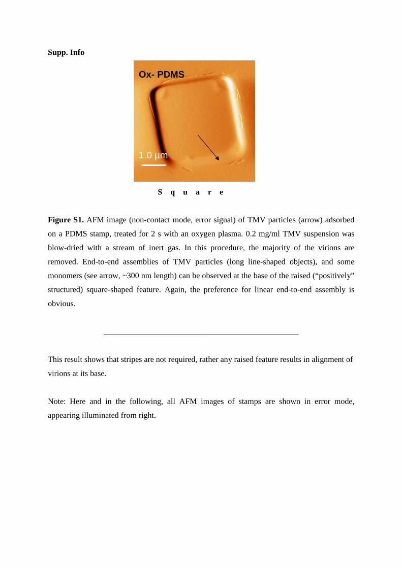
Figure S1. AFM image (non-contact mode, error signal) of TMV particles (arrow) adsorbed
on a PDMS stamp, treated for 2 s with an oxygen plasma. 0.2 mg/ml TMV suspension was
blow-dried with a stream of inert gas. In this procedure, the majority of the virions are
removed. End-to-end assemblies of TMV particles (long line-shaped objects), and some
monomers (see arrow, ~300 nm length) can be observed at the base of the raised (“positively”
structured) square-shaped feature. Again, the preference for linear end-to-end assembly is
obvious.
________________________________________________
This result shows that stripes are not required, rather any raised feature results in alignment of
virions at its base.
Note: Here and in the following, all AFM images of stamps are shown in error mode,
appearing illuminated from right.
Ox- PDMS 1.0 µm

Supp. Info.
Stripe Stripe Stripe Stripe
Figure S2. AFM image (non-contact mode, error signal) of TMV particles adsorbed on a
“positively” structured (striped) PDMS stamp surface, treated for 10 s with an oxygen plasma.
0.01 mg/ml TMV suspension was allowed to dry on the surface. End-to-end assembled TMV
particles (narrow lines of > 2 µm length, see arrows) can be discerned at the bases of the
stripes. TMV prefers end-to-end alignment at the base of protruding structures of oxidized
PDMS. The raised regions of the stamp are composed of ~1.5µm wide lines and appear
rough.
________________________________________________
The image shows that the virions align at each raised feature and easily form lines of
micrometer length.
Ox-PDMS 2.0 µm
Supp. Info.
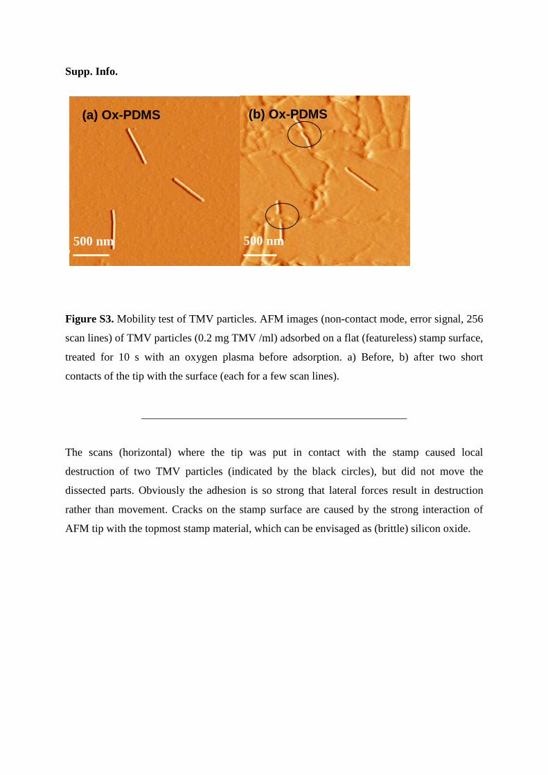
Figure S3. Mobility test of TMV particles. AFM images (non-contact mode, error signal, 256
scan lines) of TMV particles (0.2 mg TMV /ml) adsorbed on a flat (featureless) stamp surface,
treated for 10 s with an oxygen plasma before adsorption. a) Before, b) after two short
contacts of the tip with the surface (each for a few scan lines).
________________________________________________
The scans (horizontal) where the tip was put in contact with the stamp caused local
destruction of two TMV particles (indicated by the black circles), but did not move the
dissected parts. Obviously the adhesion is so strong that lateral forces result in destruction
rather than movement. Cracks on the stamp surface are caused by the strong interaction of
AFM tip with the topmost stamp material, which can be envisaged as (brittle) silicon oxide.
(a) Ox-PDMS
500 nm 500 nm
(b) Ox-PDMS

Supp. Info.
Stripe Stripe Stripe Stripe
Figure S4. AFM images (non-contact mode, error signal) of TMV particles (arrows) left on
an oxidized PDMS stamp surface after using the stamp a) once, b) twice to print TMV on
oxidized silicon wafers. The protruding features are ~1 µm wide stripes.
________________________________________________
The images show that not all virions are transferred during printing, as expected from the
transfer mechanism (even after the third printing virions were observed).
1.2 µµµµm
(a) Ox-PDMS
1.0 µµµµm
(b) Ox-PDMS

Supp. Info.
Figure S5. Confocal microscopy of fluorescent, COOH-functionalized 50 nm spheres on Ox-
PDMS. The reflection image (left) shows the protruding line pattern of the stamp, while the
simultaneously recorded fluorescence image (right) shows maximum intensity on the flat
parts, indicating discontinuous dewetting and aggregation at the bases of the lines.
________________________________________________
The use of particles with a shape and size different from TMV, but with a similar surface
functionalization, suggests that a general transfer mechanism operates, which does not depend
strongly on size and shape.

Supp. Info.
Stripe Stripe Stripe
Figure S6. AFM image (non-contact mode, error signal) of TMV particles on an oxygen
plasma treated “positively” structured stamp surface from 0.2mg/ml ethanolic suspensions of
TMV. (a) End-to-end assemblies of TMV particles generated by using a 10% ethanolic
suspension. TMV can be discernible at the base of the features (stripes) within the recesses of
the stamp structures. (b) Randomly adsorbed TMV particles generated by using 75%
ethanolic suspension of TMV (see Fig 3(b)).
________________________________________________
The variation of the ethanol/water ratio shows that the desired dewetting is only possible with
the more hydrophilic water-rich mixture used in (a).
1.0 µµµµm
a) Ox-PDMS
2.0 µµµµm
b) Ox-PDMS
Supp. Info.
Stripe
Stripe
S t
r i p
e
Str.
Stripe
Stripe Str. Str.
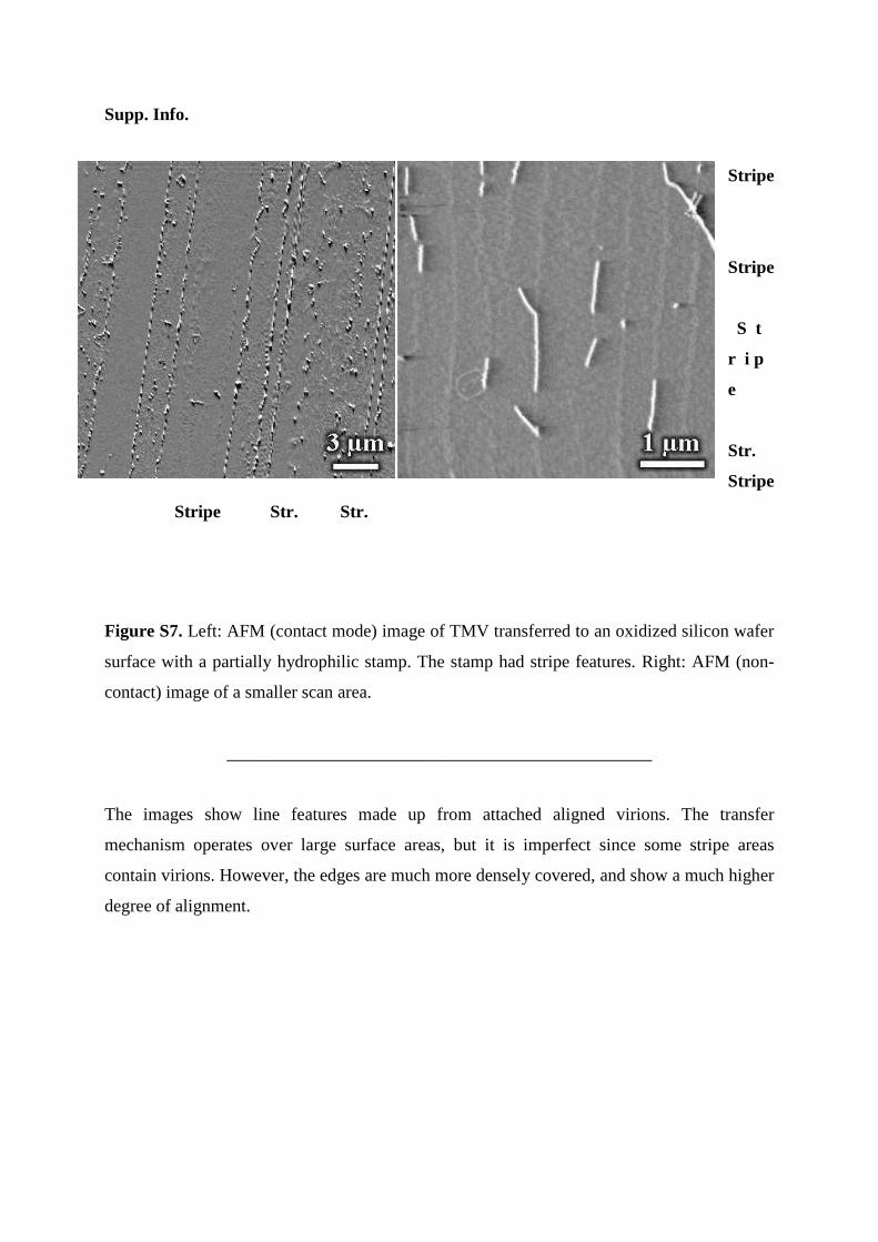
Figure S7. Left: AFM (contact mode) image of TMV transferred to an oxidized silicon wafer
surface with a partially hydrophilic stamp. The stamp had stripe features. Right: AFM (non-
contact) image of a smaller scan area.
________________________________________________
The images show line features made up from attached aligned virions. The transfer
mechanism operates over large surface areas, but it is imperfect since some stripe areas
contain virions. However, the edges are much more densely covered, and show a much higher
degree of alignment.