owner'smanual2017 125sx 150sx 250sx 250xc 300xc
TRANSCRIPT

OWNER'S MANUAL 2017
125 SX150 SX250 SX250 XC300 XC
Art. no. 3213471en


DEAR KTM CUSTOMER 1
*3213471en*3213471en
05/2016
DEAR KTM CUSTOMER
Congratulations on your decision to purchase a KTM motorcycle. You are now the owner of a state-of-the-art sports motorcycle that willgive you enormous pleasure if you service and maintain it properly.
We hope you enjoy your new vehicle!
Enter the serial numbers of your vehicle below.
Chassis number ( p. 12) Dealer's stamp
Engine number ( p. 12)
The Owner's Manual contained the latest information for this model series at the time of going to print. Minor differences due to develop-ments in design cannot be ruled out completely.
All specifications are non-binding. KTM Sportmotorcycle GmbH specifically reserves the right to modify or delete technical specifications,prices, colors, forms, materials, services, designs, equipment, etc., without prior notice and without specifying reasons, to adapt these tolocal conditions, as well as to stop production of a particular model without prior notice. KTM accepts no liability for delivery options, devi-ations from illustrations and descriptions, misprints, and other errors. The models portrayed partly contain special equipment that does notbelong to the regular scope of supply.
© 2016 KTM Sportmotorcycle GmbH, Mattighofen AustriaAll rights reservedReproduction, even in part, as well as copying of all kinds, is permitted only with the express written permission of the copyright owner.
ISO 9001(12 100 6061)According to the international quality management standard ISO 9001, KTM uses quality assurance processes that lead tothe maximum possible quality of the products.Issued by: TÜV Management Service
KTM Sportmotorcycle GmbH5230 Mattighofen, Austria
This document is valid for the following models:
125 SX EU (F6101Q0)
125 SX US (F6175Q0)
150 SX EU (F6101Q1)
150 SX US (F6175Q1)
250 SX EU (F6301Q0)
250 SX US (F6375Q0)
250 XC US (F6375Q5)
300 XC US (F6475Q5)

TABLE OF CONTENTS 2
TABLE OF CONTENTS
1 MEANS OF REPRESENTATION ..................................... 51.1 Symbols used ................................................... 51.2 Formats used.................................................... 5
2 SAFETY ADVICE........................................................... 62.1 Use definition - intended use ............................. 62.2 Safety advice.................................................... 62.3 Degrees of risk and symbols ............................... 62.4 Tampering warning............................................ 62.5 Safe operation .................................................. 72.6 Protective clothing ............................................ 72.7 Work rules........................................................ 72.8 Environment..................................................... 72.9 Owner's Manual ................................................ 8
3 IMPORTANT NOTES..................................................... 93.1 Manufacturer and implied warranty..................... 93.2 Operating and auxiliary substances ..................... 93.3 Spare parts, accessories .................................... 93.4 Service ............................................................ 93.5 Figures ............................................................ 93.6 Customer service............................................... 9
4 VIEW OF VEHICLE ..................................................... 104.1 View of vehicle, front left (example) .................. 104.2 View of vehicle, rear right (example) ................. 11
5 SERIAL NUMBERS .................................................... 125.1 Chassis number .............................................. 125.2 Type label ...................................................... 125.3 Engine number ............................................... 125.4 Fork part number ............................................ 125.5 Shock absorber article number ......................... 12
6 CONTROLS................................................................ 136.1 Clutch lever.................................................... 136.2 Hand brake lever............................................. 136.3 Throttle grip ................................................... 136.4 Kill switch...................................................... 136.5 Electric starter button (All XC models) .............. 136.6 Opening the filler cap...................................... 146.7 Closing the filler cap ....................................... 146.8 Fuel tap (All SX models) .................................. 156.9 Fuel tap (All XC models) .................................. 156.10 Choke ............................................................ 166.11 Shift lever ...................................................... 166.12 Kick starter .................................................... 166.13 Foot brake lever .............................................. 176.14 Plug-in stand (All SX models)........................... 176.15 Side stand (All XC models)............................... 176.16 Service hour counter ....................................... 17
7 PREPARING FOR USE................................................ 187.1 Advice on first use .......................................... 187.2 Running in the engine ..................................... 197.3 Preparing the vehicle for difficult riding
conditions ...................................................... 197.4 Preparing for rides on dry sand......................... 207.5 Preparing for rides on wet sand ........................ 217.6 Preparing for rides on wet and muddy
surfaces ......................................................... 227.7 Preparations for riding at high temperatures
and low speeds ............................................... 227.8 Preparing for rides at low temperature or in
snow.............................................................. 238 RIDING INSTRUCTIONS............................................. 24
8.1 Checks and maintenance work when preparingfor use ........................................................... 24
8.2 Starting.......................................................... 248.3 Starting off..................................................... 258.4 Shifting, riding ............................................... 258.5 Braking .......................................................... 258.6 Stopping, parking............................................ 268.7 Transport ....................................................... 268.8 Refueling ....................................................... 27
9 SERVICE SCHEDULE ................................................. 289.1 All SX models ................................................. 289.1.1 Additional information................................. 289.1.2 Required work ............................................ 289.1.3 Recommended work.................................... 299.2 All XC models ................................................. 299.2.1 Additional information................................. 299.2.2 Required work ............................................ 299.2.3 Recommended work.................................... 30
10 TUNING THE CHASSIS .............................................. 3110.1 Checking the basic chassis setting with the
rider's weight.................................................. 3110.2 Air suspension AER 48.................................... 3110.3 Compression damping of the shock absorber...... 3110.4 Adjusting the low-speed compression damping
of the shock absorber ...................................... 3210.5 Adjusting the high-speed compression
damping of the shock absorber......................... 3210.6 Adjusting the rebound damping of the shock
absorber......................................................... 3310.7 Measuring the rear wheel dimension
unloaded........................................................ 3410.8 Checking the static sag of the shock absorber .... 3510.9 Checking the riding sag of the shock absorber.... 3510.10 Adjusting the spring preload of the shock
absorber ..................................................... 3510.11 Adjusting the riding sag ............................... 3610.12 Checking the basic setting of the fork ............... 3710.13 Adjusting the fork air pressure.......................... 3810.14 Adjusting the compression damping of the
fork ............................................................... 3910.15 Adjusting the rebound damping of the fork ........ 3910.16 Handlebar position.......................................... 4010.17 Adjusting the handlebar position ................... 40
11 SERVICE WORK ON THE CHASSIS.............................. 4211.1 Raising the motorcycle with a lift stand............. 4211.2 Removing the motorcycle from the lift stand...... 4211.3 Bleeding the fork legs...................................... 4311.4 Cleaning the dust boots of the fork legs............. 4311.5 Removing the fork legs ................................. 4311.6 Installing the fork legs ................................. 4411.7 Removing the fork protector ............................. 4411.8 Installing the fork protector.............................. 4511.9 Removing the lower triple clamp ................... 4511.10 Installing the lower triple clamp .................... 4611.11 Checking the play of the steering head
bearing .......................................................... 4711.12 Adjusting the steering head bearing play ........ 4811.13 Greasing the steering head bearing ................ 4811.14 Removing the start number plate...................... 4911.15 Installing the start number plate....................... 4911.16 Removing the front fender ............................... 4911.17 Installing the front fender ................................ 4911.18 Removing the shock absorber ....................... 5011.19 Installing the shock absorber ........................ 51

TABLE OF CONTENTS 3
11.20 Removing the seat .......................................... 5211.21 Mounting the seat ........................................... 5311.22 Removing the air filter box cover ...................... 5311.23 Installing the air filter box cover ....................... 5311.24 Removing the air filter ................................. 5411.25 Cleaning the air filter and air filter box .......... 5411.26 Installing the air filter .................................. 5511.27 Securing the air filter box cover .................... 5511.28 Sealing the air filter box ............................... 5511.29 Removing the main silencer ............................. 5611.30 Installing the main silencer.............................. 5611.31 Changing the glass fiber yarn filling in the
main silencer .............................................. 5611.32 Removing the fuel tank ................................ 5711.33 Installing the fuel tank ................................. 5811.34 Checking the chain for dirt............................... 5911.35 Cleaning the chain .......................................... 6011.36 Checking the chain tension .............................. 6011.37 Adjusting the chain tension.............................. 6111.38 Checking the chain, rear sprocket, engine
sprocket, and chain guide................................ 6111.39 Checking the frame ..................................... 6311.40 Checking the swingarm ................................ 6311.41 Checking the throttle cable routing ................... 6311.42 Checking the rubber grip ................................. 6411.43 Adjusting basic position of clutch lever ............. 6411.44 Checking/correcting the fluid level of the
hydraulic clutch.............................................. 6511.45 Changing the hydraulic clutch fluid ............... 65
12 BRAKE SYSTEM ........................................................ 6712.1 Checking the free travel of the hand brake
lever .............................................................. 6712.2 Adjusting the basic position of the hand brake
lever .............................................................. 6712.3 Checking the brake discs ................................. 6712.4 Checking the front brake fluid level .................. 6812.5 Adding front brake fluid ............................... 6812.6 Checking the front brake linings ....................... 6912.7 Changing the front brake linings ................... 6912.8 Checking the free travel of foot brake lever ........ 7112.9 Adjusting the basic position of the foot brake
lever ........................................................... 7112.10 Checking the rear brake fluid level.................... 7212.11 Adding rear brake fluid ................................ 7312.12 Checking the rear brake linings ........................ 7312.13 Changing the rear brake linings ..................... 74
13 WHEELS, TIRES ........................................................ 7613.1 Removing the front wheel ............................. 7613.2 Installing the front wheel ............................. 7613.3 Removing the rear wheel .............................. 7713.4 Installing the rear wheel ............................... 7813.5 Checking the tire condition .............................. 7913.6 Checking the tire air pressure........................... 7913.7 Checking spoke tension ................................... 79
14 ELECTRICAL SYSTEM ................................................ 8114.1 Removing the battery (All XC models)............ 8114.2 Installing the battery (All XC models)............. 8114.3 Recharging the battery (All XC models).......... 8214.4 Changing the main fuse (All XC models)............ 83
15 COOLING SYSTEM..................................................... 8415.1 Cooling system ............................................... 8415.2 Radiator cover (All 125/150 models) ................ 84
15.3 Installing the radiator cover (All 125/150models).......................................................... 84
15.4 Removing the radiator cover (All 125/150models).......................................................... 85
15.5 Checking the antifreeze and coolant level .......... 8515.6 Checking the coolant level ............................... 8615.7 Draining the coolant .................................... 8715.8 Refilling with coolant ................................... 87
16 TUNING THE ENGINE................................................ 9016.1 Checking the play in the throttle cable .............. 9016.2 Adjusting the play in the throttle cable .......... 9016.3 Carburetor setting ........................................... 9116.4 Carburetor – idle ............................................. 9316.5 Carburetor – adjusting the idle speed ............ 9316.6 Plug-in connector of ignition timing map
adjustment..................................................... 9416.7 Changing the ignition timing map..................... 9416.8 Checking the basic position of the shift lever ..... 9516.9 Adjusting the basic position of the shift
lever ........................................................... 9516.10 Engine characteristic – auxiliary spring (All
250/300 models)............................................ 9516.11 Engine characteristic – setting the auxiliary
spring (All 250/300 models) ........................ 9617 SERVICE WORK ON THE ENGINE ............................... 97
17.1 Emptying the carburetor float chamber .......... 9717.2 Checking the gear oil level ............................... 9817.3 Changing the gear oil ................................... 9817.4 Adding gear oil .......................................... 100
18 CLEANING, CARE .................................................... 10118.1 Cleaning the motorcycle ................................ 101
19 STORAGE................................................................ 10219.1 Storage ........................................................ 10219.2 Preparing for use after storage........................ 103
20 TROUBLESHOOTING ............................................... 10421 TECHNICAL DATA.................................................... 106
21.1 Engine ......................................................... 10621.1.1 All 125 models......................................... 10621.1.2 All 150 models......................................... 10621.1.3 All 250 SX models.................................... 10721.1.4 250 XC US .............................................. 10721.1.5 300 XC US .............................................. 10821.2 Engine tightening torques .............................. 10821.2.1 All 125/150 models.................................. 10821.2.2 All 250 SX models.................................... 10921.2.3 All XC models........................................... 11021.3 Carburetor .................................................... 11221.3.1 All 125 models......................................... 11221.3.2 Carburetor - basic setting for sandy
surfaces (All 125 models).......................... 11221.3.3 Carburetor tuning (All 125 models) ............ 11321.3.4 All 150 models......................................... 11421.3.5 Basic carburetor setting for sandy surfaces
(All 150 models) ...................................... 11421.3.6 Carburetor tuning (All 150 models) ............ 11521.3.7 All 250 SX models.................................... 11621.3.8 Carburetor - basic setting for sandy
surfaces (All 250 SX models)..................... 11621.3.9 Carburetor tuning (All 250 SX models)........ 11721.3.10 250 XC US .............................................. 11821.3.11 Carburetor tuning (250 XC US) .................. 11821.3.12 300 XC US .............................................. 12021.3.13 Carburetor tuning (300 XC US) ............... 120

TABLE OF CONTENTS 4
21.4 Capacities .................................................... 12121.4.1 Gear oil.................................................... 12121.4.2 Coolant .................................................... 12121.4.3 Fuel ........................................................ 12121.5 Chassis ........................................................ 12121.6 Electrical system........................................... 12221.7 Tires ............................................................ 12221.8 Fork............................................................. 12221.8.1 All 125/150 models.................................. 12221.8.2 All 250 SX models.................................... 12321.8.3 All XC models........................................... 12321.9 Shock absorber ............................................. 12321.9.1 All 125/150 models.................................. 12321.9.2 250 SX EU .............................................. 12421.9.3 250 SX US .............................................. 12421.9.4 All XC models........................................... 12521.10 Chassis tightening torques ............................. 126
22 SUBSTANCES ......................................................... 12723 AUXILIARY SUBSTANCES ........................................ 12924 STANDARDS ........................................................... 13025 LIST OF ABBREVIATIONS......................................... 131INDEX ............................................................................ 132

1 MEANS OF REPRESENTATION 5
1.1 Symbols usedThe meaning of specific symbols is described below.
Indicates an expected reaction (e.g. of a work step or a function).
Indicates an unexpected reaction (e.g. of a work step or a function).
All work marked with this symbol requires specialist knowledge and technical understanding. In the interest ofyour own safety, have these jobs performed by an authorized KTM workshop. There, your motorcycle will be opti-mally cared for by specially trained experts using the specialist tools required.
Indicates a page reference (more information is provided on the specified page).
Indicates information with more details or tips.
Indicates the result of a testing step.
1.2 Formats usedThe typographical formats used in this document are explained below.
Specific name Identifies a proprietary name.
Name® Identifies a protected name.
Brand™ Identifies a brand available on the open market.
Underlined terms Refer to technical details of the vehicle or indicate technical terms that are explained inthe glossary.

2 SAFETY ADVICE 6
2.1 Use definition - intended use(All SX models)
KTM sport motorcycles are designed and built to withstand the normal stresses and strains of competitive use. The motorcyclescomply with currently valid regulations and categories of the top international motorsport organizations.
InfoThe motorcycle may only be used in closed off areas remote from public road traffic.
(All XC models)KTM sport motorcycles are designed and built to withstand the normal stresses and strains of competitive use. The motorcyclescomply with currently valid regulations and categories of the top international motorsport organizations.
InfoThis motorcycle is designed for use in offroad endurance competition and not primarily for use in motocross.
2.2 Safety adviceA number of safety instructions need to be followed to operate the vehicle safely. Therefore, read this manual carefully. The safetyinstructions are highlighted in the text and are referred to at the relevant passages.
InfoThe vehicle has various information and warning labels at prominent locations. Do not remove information/warning labels. Ifthey are missing, you or others may not recognize dangers and may therefore be injured.
2.3 Degrees of risk and symbols
DangerIndicates a danger that will immediately and invariably lead to fatal or serious permanent injury if the appropriate measures arenot taken.
WarningIndicates a danger that is likely to lead to fatal or serious injury if the appropriate measures are not taken.
CautionIndicates a danger that may lead to minor injuries if the appropriate measures are not taken.
NoteIndicates a danger that will lead to considerable machine and material damage if the appropriate measures are not taken.
WarningIndicates a danger that will lead to environmental damage if the appropriate measures are not taken.
2.4 Tampering warningTampering with the noise control system is prohibited. Federal law prohibits the following acts or the causing thereof:
1 The removal or rendering inoperative by any person other than for purposes of maintenance, repair, or replacement, of any deviceor element of design incorporated into any new vehicle for the purpose of noise control prior to its sale or delivery to the ultimatepurchaser or while it is in use, or
2 the use of the vehicle after such device or element of design has been removed or rendered inoperative by any person.
Among those acts presumed to constitute tampering are the acts listed below:
1 Removal or puncturing of the main silencer, baffles, header pipes or any other components which conduct exhaust gases.
2 Removal or puncturing of parts of the intake system.
3 Lack of proper maintenance.
4 Replacing moving part of the vehicle, or parts of the exhaust or intake system, with parts other than those specified by the manu-facturer.

2 SAFETY ADVICE 7
2.5 Safe operation
DangerDanger of accidents A rider who is not fit to ride poses a danger to him or herself and others.
– Do not operate the vehicle if you are not fit to ride due to alcohol, drugs or medication.
– Do not operate the vehicle if you are physically or mentally impaired.
DangerDanger of poisoning Exhaust gases are toxic and inhaling them may result in unconsciousness and death.
– Always make sure there is sufficient ventilation when running the engine.
– Use an effective exhaust extraction system when starting or running the engine in an enclosed space.
WarningDanger of burns Some vehicle components become very hot when the vehicle is operated.
– Do not touch any parts such as the exhaust system, radiator, engine, shock absorber, or brake system before the vehicleparts have cooled down.
– Let the vehicle parts cool down before you perform any work on the vehicle.
Only operate the vehicle when it is in perfect technical condition, in accordance with its intended use, and in a safe and environmen-tally compatible manner.The vehicle should only be used by trained persons.Have malfunctions that impair safety promptly eliminated by an authorized KTM workshop.Adhere to the information and warning labels on the vehicle.
2.6 Protective clothing
WarningRisk of injury Missing or poor protective clothing presents an increased safety risk.
– Wear appropriate protective clothing such as helmet, boots, gloves as well as trousers and a jacket with protectors on allrides.
– Always wear protective clothing that is in good condition and meets the legal regulations.
In the interest of your own safety, KTM recommends that you only operate the vehicle while wearing protective clothing.
2.7 Work rulesSpecial tools are necessary for certain tasks. The tools are not contained in the vehicle but can be ordered under the number in paren-theses. E.g.: bearing puller (15112017000)During assembly, non-reusable parts (e.g. self-locking screws and nuts, seals and seal rings, O-rings, pins, lock washers) must bereplaced by new parts.In some instances, a thread locker (e.g. Loctite®) is required. The manufacturer instructions for use must be followed.After disassembly, clean the parts that are to be reused and check them for damage and wear. Change damaged or worn parts.After you complete the repair or service work, check the operating safety of the vehicle.
2.8 EnvironmentIf you use your motorcycle responsibly, you can ensure that problems and conflicts do not occur. To protect the future of the motorcy-cle sport, make sure that you use your motorcycle legally, display environmental consciousness, and respect the rights of others.When disposing of used oil, other operating and auxiliary fluids, and used components, comply with the laws and regulations of therespective country.Because motorcycles are not subject to the EU regulations governing the disposal of used vehicles, there are no legal regulations thatpertain to the disposal of an end-of-life motorcycle. Your authorized KTM dealer will be glad to advise you.

2 SAFETY ADVICE 8
2.9 Owner's ManualIt is important that you read this Owner's Manual carefully and completely before making your first trip. The Owner's Manual containsuseful information and many tips on how to operate, handle, and maintain your motorcycle. Only then will you find out how to cus-tomize the vehicle ideally for your own use and how you can protect yourself from injury.Keep the Owner's Manual in an accessible place to enable you to refer to it as needed.If you would like to know more about the vehicle or have questions on the material you read, please contact an authorized KTM dealer.The Owner's Manual is an important component of the vehicle and must be handed over to the new owner if the vehicle is sold.

3 IMPORTANT NOTES 9
3.1 Manufacturer and implied warrantyThe work specified in the service schedule may only be performed in an authorized KTM workshop and must be recorded in both theService & Warranty Booklet and in KTM Dealer.net, otherwise any warranty coverage will become void. Damage or secondary damagecaused by tampering with and/or conversions on the vehicle are not covered by the warranty.Additional information on the manufacturer or implied warranty and the procedures involved can be found in the Service & WarrantyBooklet.
3.2 Operating and auxiliary substances
WarningEnvironmental hazard Improper handling of fuel is a danger to the environment.
– Do not allow fuel to enter the groundwater, the soil, or the sewage system.
Use operating and auxiliary substances (such as fuel and lubricants) as specified in the Owner's Manual.
3.3 Spare parts, accessoriesFor your own safety, only use spare parts and accessory products that are approved and/or recommended by KTM and have theminstalled by an authorized KTM workshop. KTM accepts no liability for other products and any resulting damage or loss.Certain spare parts and accessory products are specified in parentheses in the descriptions. Your authorized KTM dealer will be gladto advise you.
The current KTM PowerParts for your vehicle can be found on the KTM website.International KTM Website: http://www.ktm.com
3.4 ServiceA prerequisite for perfect operation and prevention of premature wear is that the service, care, and tuning work on the engine andchassis is properly carried out as described in the Owner's Manual. Incorrect adjustment and tuning of the engine and chassis canlead to damage and breakage of components.Use of the vehicle under difficult conditions, such as on sand or on wet and muddy surfaces, can lead to considerably more rapid wearof components such as the drive train, brake system, or suspension components. For this reason, it may be necessary to inspect orreplace parts before the next scheduled service.It is imperative that you adhere to the stipulated run-in times and service intervals. If you observe these exactly, you will ensure amuch longer service life for your motorcycle.
3.5 FiguresThe figures contained in the manual may depict special equipment.In the interest of clarity, some components may be shown disassembled or may not be shown at all. It is not always necessary to dis-assemble the component to perform the activity in question. Please follow the instructions in the text.
3.6 Customer serviceYour authorized KTM dealer will be happy to answer any questions you may have on your vehicle and KTM.
A list of authorized KTM dealers can be found on the KTM website.International KTM Website: http://www.ktm.com

4 VIEW OF VEHICLE 10
4.1 View of vehicle, front left (example)
H01327-10
1 Hand brake lever ( p. 13)
2 Kill switch ( p. 13)
3 Clutch lever ( p. 13)
4 Air filter box cover
5 Plug-in stand
6 Shift lever ( p. 16)
7 Choke ( p. 16)
8 Fuel tap

4 VIEW OF VEHICLE 11
4.2 View of vehicle, rear right (example)
H01329-10
1 Seat
2 Filler cap
3 Throttle grip ( p. 13)
4 Kick starter ( p. 16)
5 Foot brake lever ( p. 17)
6 Shock absorber compression adjustment
7 Level viewer for brake fluid, rear
8 Shock absorber rebound adjustment

5 SERIAL NUMBERS 12
5.1 Chassis number
401945-10
The chassis number is stamped on the right side of the steering head.
5.2 Type label
401946-10
The type label is fixed to the front of the steering head.
5.3 Engine number
401949-10
The engine number is stamped on the left side of the engine under the enginesprocket.
5.4 Fork part number
401947-10
The fork part number is stamped on the inner side of the fork stub.
5.5 Shock absorber article number
0011
401948-10
Shock absorber article number is stamped on the top of the shock absorber abovethe adjusting ring towards the engine side.

6 CONTROLS 13
6.1 Clutch lever
F00009-10
Clutch lever is fitted on the handlebar on the left.The clutch is activated hydraulically and adjusts itself automatically.
6.2 Hand brake lever
F00001-10
Hand brake lever is fitted on the right side of the handlebar.The front brake is engaged using the hand brake lever.
6.3 Throttle grip
F00001-11
Throttle grip is fitted on the right side of the handlebar.
6.4 Kill switch
F00002-10
The kill switch is fitted on the left side of the handlebar.
Possible states• Kill switch in basic position – In this position, the ignition circuit is closed, and
the engine can be started.• Kill switch pressed – In this position, the ignition circuit is interrupted, a run-
ning engine stops, and a non-running engine will not start.
6.5 Electric starter button (All XC models)
K00487-10
The electric starter button is fitted on the right side of the handlebar.
Possible states• Electric starter button in basic position• Electric starter button pressed – In this position, the electric starter is actuated.

6 CONTROLS 14
6.6 Opening the filler cap
DangerFire hazard Fuel is highly flammable.
The fuel in the fuel tank expands when warm and can escape if overfilled.
– Do not refuel the vehicle in the vicinity of open flames or lit cigarettes.
– Switch off the engine for refueling.
– Make sure that no fuel is spilled; particularly not on hot parts of the vehicle.
– If any fuel is spilled, wipe it off immediately.
– Observe the specifications for refueling.
WarningDanger of poisoning Fuel is poisonous and a health hazard.
– Avoid skin, eye and clothing contact with fuel.
– Immediately consult a doctor if you swallow fuel.
– Do not inhale fuel vapors.
– In case of skin contact, rinse the affected area with plenty of water.
– Rinse the eyes thoroughly with water, and consult a doctor in case of fuel contact with the eyes.
– Change your clothing in case of fuel spills on them.
– Keep fuels correctly in a suitable canister, and out of the reach of children.
WarningEnvironmental hazard Improper handling of fuel is a danger to the environment.
– Do not allow fuel to enter the groundwater, the soil, or the sewage system.
F00003-10
(All SX models)– Turn filler cap counterclockwise and lift it off.
K00508-10
(All XC models)– Press release button, turn the filler cap counterclockwise, and lift it off.
6.7 Closing the filler cap
F00003-11
(All SX models)– Mount filler cap and turn it clockwise until the fuel tank is tightly closed.
InfoRun the fuel tank breather hose without kinks.

6 CONTROLS 15
K00508-11
(All XC models)– Mount filler cap and turn it clockwise until the release button engages.
InfoRun the fuel tank breather hose without kinks.
6.8 Fuel tap (All SX models)
K00510-10
Fuel tap is on the left of the fuel tank.Open or close the supply of fuel to the carburetor using tap handle on the fuel tap.
Possible states• Fuel supply closed OFF – Fuel cannot flow from the fuel tank to the carburetor.• Fuel supply open ON – Fuel can flow from the fuel tank to the carburetor. The fuel
tank empties completely.
6.9 Fuel tap (All XC models)
K00488-10
Fuel tap is on the left of the fuel tank.Open or close the supply of fuel to the carburetor using tap handle on the fuel tap.
Possible states• Fuel supply closed OFF – Fuel cannot flow from the fuel tank to the carburetor.• Fuel supply open ON – Fuel can flow from the fuel tank to the carburetor. The fuel
tank empties down to the reserve level.• Fuel reserve supply open RES – Fuel can flow from the fuel tank to the carburetor.
The fuel tank empties completely.

6 CONTROLS 16
6.10 Choke
F00005-10
Choke is fitted on the left side of the carburetor.Activating the choke function frees a drill hole in the carburetor through which theengine can draw extra fuel. This results in a richer fuel-air mixture, which is neededfor a cold start.
InfoIf the engine is warm, the choke function must be deactivated.
Possible states• Choke function activated – The choke lever is pulled out to the stop.• Choke function deactivated – The choke lever is pushed in to the stop.
6.11 Shift lever
401950-10
Shift lever is mounted on the left of the engine.
401950-11
(All 125/150 models, All XC models)The gear positions can be seen in the photograph.The neutral or idle position is between the first and second gears.
401950-13
(All 250 SX models)The gear positions can be seen in the photograph.The neutral or idle position is between the first and second gears.
6.12 Kick starter
0011
401954-10
Kick starter is fitted on the right side of the engine.The top part of the kick starter pivots.
InfoBefore riding, swing the top part of the kick starter inward toward the engine.

6 CONTROLS 17
6.13 Foot brake lever
401956-10
Foot brake lever is located in front of the right footrest.The foot brake lever is used to activate the rear brake.
6.14 Plug-in stand (All SX models)
0011
402001-10
The holder for plug-in stand is on the left side of the wheel spindle.The plug-in stand is used to park the motorcycle.
InfoRemove the plug-in stand before riding.
6.15 Side stand (All XC models)
401943-10
Side stand is located on the left side of the vehicle.
401944-10
The side stand is used for parking the motorcycle.
InfoWhen you are riding, side stand must be folded up and secured with rubberband.
6.16 Service hour counter
K00484-10
The service hour counter is fitted in front of the handlebar.It shows the total number of service hours of the engine.The service hour counter begins counting when the engine is started and stops whenthe engine is switched off.
InfoIt is not possible to delete or adjust anything on the service hour counter.

7 PREPARING FOR USE 18
7.1 Advice on first use
DangerDanger of accidents A rider who is not fit to ride poses a danger to him or herself and others.
– Do not operate the vehicle if you are not fit to ride due to alcohol, drugs or medication.
– Do not operate the vehicle if you are physically or mentally impaired.
WarningRisk of injury Missing or poor protective clothing presents an increased safety risk.
– Wear appropriate protective clothing such as helmet, boots, gloves as well as trousers and a jacket with protectors on allrides.
– Always wear protective clothing that is in good condition and meets the legal regulations.
WarningDanger of crashing Different tire tread patterns on the front and rear wheel impair the handling characteristic.
Different tire tread patterns can make the vehicle significantly more difficult to control.
– Make sure that only tires with a similar tire tread pattern are fitted to the front and rear wheel.
WarningDanger of accidents An unadapted riding style impairs the handling characteristic.
– Adapt your riding speed to the road conditions and your riding ability.
WarningDanger of accidents The vehicle is not designed to carry passengers.
– Do not ride with a passenger.
WarningDanger of accidents The brake system fails in the event of overheating.
If the foot brake lever is not released, the brake linings drag continuously.
– Take your foot off the foot brake lever when you are not braking.
WarningDanger of accidents Total weight and axle loads influence the handling characteristic.
– Do not exceed the maximum permissible overall weight or the axle loads.
WarningRisk of misappropriation People who act without authorization endanger themselves and others.
– Do not leave the vehicle unattended if the engine is running.
– Protect the vehicle against access by unauthorized persons.
InfoWhen using your motorcycle, remember that others may feel disturbed by excessive noise.
– Make sure that the pre-delivery inspection work has been carried out by an authorized KTM workshop.
You receive a delivery certificate and the Service and Warranty Booklet at vehicle handover.
– Before your first trip, read the entire Owner's Manual carefully.
– Get to know the controls.
– Adjust the basic position of clutch lever. ( p. 64)
– Adjust the basic position of the hand brake lever. ( p. 67)
– Adjust the basic position of the foot brake lever. ( p. 71)
– Adjust the basic position of the shift lever. ( p. 95)
– Become accustomed to the handling of the motorcycle on suitable terrain.
InfoYour motorcycle is not authorized for riding on public roads.When offroad, being accompanied by another person on another vehicle so that you can help each other is recommended.
7 PREPARING FOR USE 19
– Try also to ride as slowly as possible and in a standing position to get a better feeling for the motorcycle.
– Do not make any off-road trips that exceed your ability and experience.
– Hold the handlebar firmly with both hands and keep your feet on the footrests when riding.
– Do not take luggage along.
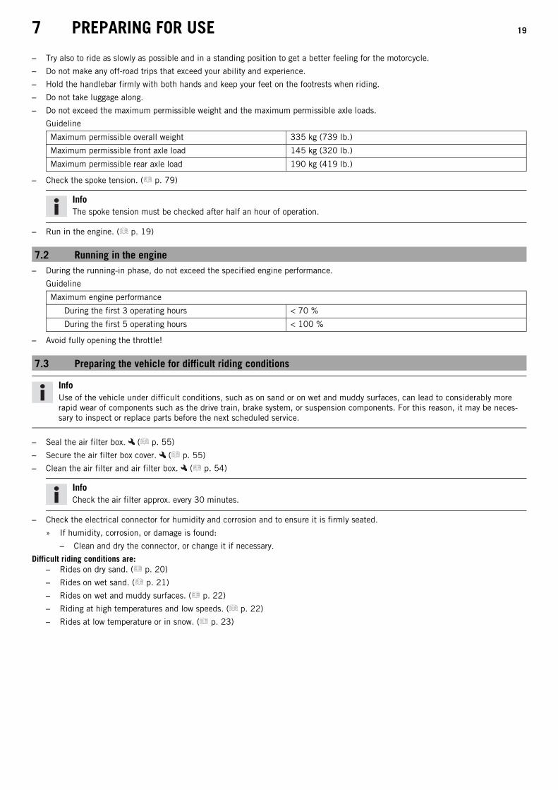
– Do not exceed the maximum permissible weight and the maximum permissible axle loads.
Guideline
Maximum permissible overall weight 335 kg (739 lb.)
Maximum permissible front axle load 145 kg (320 lb.)
Maximum permissible rear axle load 190 kg (419 lb.)
– Check the spoke tension. ( p. 79)
InfoThe spoke tension must be checked after half an hour of operation.
– Run in the engine. ( p. 19)
7.2 Running in the engine– During the running-in phase, do not exceed the specified engine performance.
Guideline
Maximum engine performance
During the first 3 operating hours < 70 %
During the first 5 operating hours < 100 %
– Avoid fully opening the throttle!
7.3 Preparing the vehicle for difficult riding conditions
InfoUse of the vehicle under difficult conditions, such as on sand or on wet and muddy surfaces, can lead to considerably morerapid wear of components such as the drive train, brake system, or suspension components. For this reason, it may be neces-sary to inspect or replace parts before the next scheduled service.
– Seal the air filter box. ( p. 55)
– Secure the air filter box cover. ( p. 55)
– Clean the air filter and air filter box. ( p. 54)
InfoCheck the air filter approx. every 30 minutes.
– Check the electrical connector for humidity and corrosion and to ensure it is firmly seated.
» If humidity, corrosion, or damage is found:
– Clean and dry the connector, or change it if necessary.
Difficult riding conditions are:– Rides on dry sand. ( p. 20)
– Rides on wet sand. ( p. 21)
– Rides on wet and muddy surfaces. ( p. 22)
– Riding at high temperatures and low speeds. ( p. 22)
– Rides at low temperature or in snow. ( p. 23)

7 PREPARING FOR USE 20
7.4 Preparing for rides on dry sand
M01129-01
– Check the radiator cap.
Value on the radiator cap 1.8 bar (26 psi)
» If the indicated value does not correspond to the required value:
WarningDanger of scalding During motorcycle operation, the coolant getsvery hot and is under pressure.
– Do not open the radiator, the radiator hoses or other cooling sys-tem components if the engine or the cooling system are at oper-ating temperature.
– Allow the cooling system and the engine to cool down before youopen the radiator, the radiator hoses or other components of thecooling system.
– In the event of scalding, rinse the area affected immediatelywith lukewarm water.
– Change the radiator cap.
M01104-01
– Fit a dust cover on the air filter.
Dust cover for air filter (79006920000)
InfoSee the KTM PowerParts fitting instructions.
M01105-01
– Fit a sand cover on the air filter.
Sand cover for air filter (79006922000)
InfoSee the KTM PowerParts fitting instructions.
M01107-01
– Adjust the carburetor jetting and setting.
InfoYour authorized KTM workshop can recommend the right carburetor tuning.
600868-01
– Clean the chain.
Chain cleaner ( p. 129)
– Fit the steel sprocket.
TipDo not grease the chain.
– Clean the radiator fins.
– Straighten bent radiator fins carefully.
ConditionRegular use in sand
7 PREPARING FOR USE 21
– Change the piston every 10 operating hours.
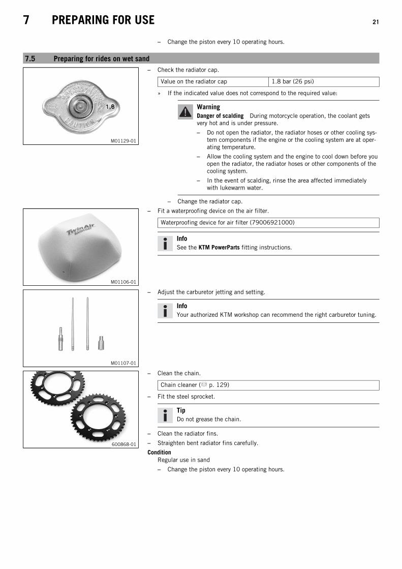
7.5 Preparing for rides on wet sand
M01129-01
– Check the radiator cap.
Value on the radiator cap 1.8 bar (26 psi)
» If the indicated value does not correspond to the required value:
WarningDanger of scalding During motorcycle operation, the coolant getsvery hot and is under pressure.
– Do not open the radiator, the radiator hoses or other cooling sys-tem components if the engine or the cooling system are at oper-ating temperature.
– Allow the cooling system and the engine to cool down before youopen the radiator, the radiator hoses or other components of thecooling system.
– In the event of scalding, rinse the area affected immediatelywith lukewarm water.
– Change the radiator cap.
M01106-01
– Fit a waterproofing device on the air filter.
Waterproofing device for air filter (79006921000)
InfoSee the KTM PowerParts fitting instructions.
M01107-01
– Adjust the carburetor jetting and setting.
InfoYour authorized KTM workshop can recommend the right carburetor tuning.
600868-01
– Clean the chain.
Chain cleaner ( p. 129)
– Fit the steel sprocket.
TipDo not grease the chain.
– Clean the radiator fins.
– Straighten bent radiator fins carefully.
ConditionRegular use in sand
– Change the piston every 10 operating hours.

7 PREPARING FOR USE 22
7.6 Preparing for rides on wet and muddy surfaces
M01106-01
– Fit a waterproofing device on the air filter.
Waterproofing device for air filter (79006921000)
InfoSee the KTM PowerParts fitting instructions.
M01107-01
– Adjust the carburetor jetting and setting.
InfoYour authorized KTM workshop can recommend the right carburetor tuning.
600868-01
– Fit the steel sprocket.
– Clean the motorcycle. ( p. 101)
– Straighten bent radiator fins carefully.
7.7 Preparations for riding at high temperatures and low speeds
M01129-01
– Check the radiator cap.
Value on the radiator cap 1.8 bar (26 psi)
» If the displayed value does not equal the setpoint value:
WarningDanger of scalding During motorcycle operation, the coolant getsvery hot and is under pressure.
– Do not open the radiator, the radiator hoses or other cooling sys-tem components if the engine or the cooling system are at oper-ating temperature.
– Allow the cooling system and the engine to cool down before youopen the radiator, the radiator hoses or other components of thecooling system.
– In the event of scalding, rinse the area affected immediatelywith lukewarm water.
– Change the radiator cap.
600868-01
– Adjust the secondary ratio to the terrain.
InfoThe engine oil heats up quickly when the clutch is operated frequently dueto an excessively high secondary drive.
– Clean the chain.
Chain cleaner ( p. 129)
– Clean the radiator fins.

7 PREPARING FOR USE 23
– Carefully align bent radiator fins.
– Check the coolant level. ( p. 86)
7.8 Preparing for rides at low temperature or in snow
M01106-01
– Fit a waterproofing device on the air filter.
Waterproofing device for air filter (79006921000)
InfoSee the KTM PowerParts fitting instructions.
M01107-01
– Adjust the carburetor jetting and setting.
InfoYour authorized KTM workshop can recommend the right carburetor tuning.

8 RIDING INSTRUCTIONS 24
8.1 Checks and maintenance work when preparing for use
InfoBefore riding the vehicle, always check its condition and operating safety.The vehicle must be in perfect technical condition when used.
– Check the gear oil level. ( p. 98)
– Check the front brake fluid level. ( p. 68)
– Check the rear brake fluid level. ( p. 72)
– Check the front brake linings. ( p. 69)
– Check the rear brake linings. ( p. 73)
– Check that the brake system is functioning properly.
– Check the coolant level. ( p. 86)
– Check the chain for dirt. ( p. 59)
– Check the chain, rear sprocket, engine sprocket, and chain guide. ( p. 61)
– Check the chain tension. ( p. 60)
– Check the tire condition. ( p. 79)
– Check the tire air pressure. ( p. 79)
– Check the spoke tension. ( p. 79)
– Clean the dust boots of the fork legs. ( p. 43)
– Bleed the fork legs. ( p. 43)
– Check the air filter.
– Check the settings of all controls and ensure that they can be operated smoothly.
– Check all screws, nuts and hose clamps regularly for tightness.
– Check the fuel supply.
8.2 Starting
DangerDanger of poisoning Exhaust gases are toxic and inhaling them may result in unconsciousness and death.
– Always make sure there is sufficient ventilation when running the engine.
– Use an effective exhaust extraction system when starting or running the engine in an enclosed space.
NoteEngine damage High revving speed with a cold engine negatively impacts the lifespan of the engine.
– Always run the engine warm at a low speed.
InfoIf the motorcycle is unwilling to start, the cause can be old fuel in the float chamber. The flammable elements of the fuelevaporate after a long time of standing.If the float chamber is filled with fresh fuel, the engine starts immediately.
The motorcycle has been out of use for more than 1 week– Empty the carburetor float chamber. ( p. 97)
(All SX models)– Turn handle of the fuel tap to the ON position. (Figure K00510-10 p. 15)
Fuel can flow from the fuel tank to the carburetor.
– Remove the plug-in stand.
– Shift the transmission to idle.
ConditionThe engine is cold
– Pull the choke lever out as far as possible.
– Press the kick starter robustly through its full range.
InfoDo not open the throttle.
8 RIDING INSTRUCTIONS 25
(All XC models)– Turn handle of the fuel tap to the ON position. (Figure K00488-10 p. 15)
Fuel can flow from the fuel tank to the carburetor.
– Remove the motorcycle from the side stand.
– Shift the transmission to idle.
ConditionThe engine is cold
– Pull the choke lever out as far as possible.
– Press the electric starter button or press the kick starter robustly through its full range.
InfoDo not open the throttle.
8.3 Starting off
InfoThe plug-in stand must be removed before riding.While riding, the side stand must be folded up and secured with the rubber band.
– Pull the clutch lever, shift into first gear, release the clutch lever slowly and at the same time open the throttle gently.
8.4 Shifting, riding
WarningDanger of accidents If you change down at high engine speed, the rear wheel blocks and the engine races.
– Do not change into a low gear at high engine speed.
InfoIf you hear unusual noises while riding, stop immediately, switch off the engine, and contact an authorized KTM workshop.First gear is used for starting off or for steep inclines.
– Shift into a higher gear when conditions allow (incline, road situation, etc.). To do so, release the throttle while simultaneouslypulling the clutch lever, shift into the next gear, release the clutch lever and open the throttle.
– If the choke function was activated, deactivate it after the engine has warmed up.
– After reaching maximum speed by fully opening the throttle grip, turn the throttle back so it is ¾ open. This will barely reduce thespeed but fuel consumption will be considerably lower.
– Always open the throttle only as much as the engine can handle – abrupt throttle opening increases fuel consumption.
– To shift down, brake and close the throttle at the same time.
– Pull the clutch lever and shift into a lower gear, release the clutch lever slowly, and either open the throttle or shift again.
– Switch off the engine if you expect to be standing for a long time.
Guideline
≥ 2 min
– Avoid frequent and longer slipping of the clutch. As a result the engine oil, engine and cooling system heat up.
– Ride with a low engine speed instead of with a high engine speed and a slipping clutch.
8.5 Braking
WarningDanger of accidents Excessively forceful application of the brakes blocks the wheels.
– Adjust application of the brakes to the respective riding situation and riding surface conditions.
WarningDanger of accidents A spongy pressure point on the front or rear brake reduces braking efficiency.
– Check the brake system and do not continue riding until the problem is eliminated. (Your authorized KTM workshop will beglad to help.)

8 RIDING INSTRUCTIONS 26
WarningDanger of accidents Moisture and dirt impair the brake system.
– Brake carefully several times to dry out and remove dirt from the brake linings and the brake discs.
– On sandy, wet or slippery surfaces, use the rear brake.
– Braking should always be completed before you go into a bend. Change down to a lower gear appropriate to your road speed.
– Make use of the braking effect of the engine when driving down long downhill stretches. To do so, shift back one or two gears, butdo not overrev the engine. You will need to apply the brakes far less often and the brake system will not overheat.
8.6 Stopping, parking
WarningRisk of misappropriation People who act without authorization endanger themselves and others.
– Do not leave the vehicle unattended if the engine is running.
– Protect the vehicle against access by unauthorized persons.
WarningDanger of burns Some vehicle components become very hot when the vehicle is operated.
– Do not touch any parts such as the exhaust system, radiator, engine, shock absorber, or brake system before the vehicleparts have cooled down.
– Let the vehicle parts cool down before you perform any work on the vehicle.
NoteFire hazard Hot vehicle components pose a fire hazard and explosion risk.
– Do not park the vehicle near to materials which are highly flammable or explosive.
– Allow the vehicle to cool down before covering it.
NoteMaterial damage The vehicle may be damaged by incorrect procedure when parking.
Significant damage may be caused if the vehicle rolls away or falls over.The components for parking the vehicle are designed only for the weight of the vehicle.
– Park the vehicle on a firm and level surface.
– Ensure that nobody sits on the vehicle when the vehicle is parked on a stand.
– Apply the brakes on the motorcycle.
– Shift gear to neutral.
– Press and hold the kill switch while the engine is idling until the engine stops.
(All SX models)– Turn handle of the fuel tap to the OFF position. (Figure K00510-10 p. 15)
– Rest the vehicle on the plug-in stand.
(All XC models)– Turn handle of the fuel tap to the OFF position. (Figure K00488-10 p. 15)
– Rest the vehicle on the side stand.
8.7 Transport
NoteDanger of damage The parked vehicle can roll away or fall over.
– Park the vehicle on a firm and level surface.
NoteFire hazard Hot vehicle components pose a fire hazard and explosion risk.
– Do not park the vehicle near to materials which are highly flammable or explosive.
– Allow the vehicle to cool down before covering it.

8 RIDING INSTRUCTIONS 27
401475-01
– Switch off the engine.
– Use tension belts or other suitable devices to secure the motorcycle against acci-dents or falling over.
8.8 Refueling
DangerFire hazard Fuel is highly flammable.
The fuel in the fuel tank expands when warm and can escape if overfilled.
– Do not refuel the vehicle in the vicinity of open flames or lit cigarettes.
– Switch off the engine for refueling.
– Make sure that no fuel is spilled; particularly not on hot parts of the vehicle.
– If any fuel is spilled, wipe it off immediately.
– Observe the specifications for refueling.
WarningDanger of poisoning Fuel is poisonous and a health hazard.
– Avoid skin, eye and clothing contact with fuel.
– Immediately consult a doctor if you swallow fuel.
– Do not inhale fuel vapors.
– In case of skin contact, rinse the affected area with plenty of water.
– Rinse the eyes thoroughly with water, and consult a doctor in case of fuel contact with the eyes.
– Change your clothing in case of fuel spills on them.
WarningEnvironmental hazard Improper handling of fuel is a danger to the environment.
– Do not allow fuel to enter the groundwater, the soil, or the sewage system.
– Switch off the engine.
– Open the filler cap. ( p. 14)
400382-10
– Fill the fuel tank with fuel up to measurement.
Guideline
Measurement of 35 mm (1.38 in)
Total fuel tankcapacity, approx.(All SX models)
7 l (1.8 US gal) Super unleaded (98 octane) mixedwith 2-stroke engine oil (1:40)( p. 128) (All 125/150 models)
Super unleaded (95 octane) mixedwith 2-stroke engine oil (1:60)( p. 128) (All 250 SX models)
Total fuel tankcapacity, approx.(All XC models)
10 l (2.6 US gal) Super unleaded (95 octane) mixedwith 2-stroke engine oil (1:60)( p. 128)
Engine oil, 2-stroke ( p. 127)
– Close the filler cap. ( p. 14)

9 SERVICE SCHEDULE 28
9.1 All SX models
9.1.1 Additional information
Any further work that results from the required work or from the recommended work must be ordered separately and can be invoicedseparately.
9.1.2 Required work
Every 20 operating hours
Every 10 operating hours/after every race
Once after 1 operating hour
Change the gear oil. (All 125/150 models) ● ●
Change the gear oil. (All 250 SX models) ●
Check the front brake linings. ( p. 69) ● ●
Check the rear brake linings. ( p. 73) ● ●
Check the brake discs. ( p. 67) ● ●
Check the brake lines for damage and leakage. ● ●
Check the rear brake fluid level. ( p. 72) ● ●
Check the free travel of the foot brake lever. ( p. 71) ● ●
Check the frame and swingarm. ● ●
Check the swingarm bearing. ●
Check the heim joints at the top of the shock absorber. ● ●
Check the shock absorber linkage. ● ●
Check the tire condition. ( p. 79) ○ ● ●
Check the tire air pressure. ( p. 79) ○ ● ●
Check the wheel bearing for play. ● ●
Check the wheel hubs. ● ●
Check the rim run-out. ○ ● ●
Check the spoke tension. ( p. 79) ○ ● ●
Check the chain, rear sprocket, engine sprocket, and chain guide. ( p. 61) ● ●
Check the chain tension. ( p. 60) ○ ● ●
Grease all moving parts (e.g., hand lever, chain, ...) and check for smooth operation. ● ●
Check/correct the fluid level of the hydraulic clutch. ( p. 65) ● ●
Check the front brake fluid level. ( p. 68) ● ●
Check the free travel of the hand brake lever. ( p. 67) ● ●
Check the play of the steering head bearing. ( p. 47) ○ ● ●
Change the spark plug and spark plug connector. (All 125/150 models) ● ●
Change the spark plug and spark plug connector. (All 250 SX models) ●
Check all hoses (e.g. fuel, cooling, bleeder, drainage, etc.) and sleeves for cracking, leaks, and incorrect routing. ○ ● ●
Check the antifreeze and coolant level. ( p. 85) ○ ● ●
Check the cables for damage and routing without sharp bends. ● ●
Check that the throttle cables are undamaged, routed without sharp bends, and set correctly. ○ ● ●
Clean the air filter and air filter box. ( p. 54) ● ●
Change glass fiber yarn filling in the main silencer. ( p. 56) ●
Check the screws and nuts for tightness. ○ ● ●
Check idle. ○ ● ●
Final check: Check the vehicle for safe operation and take a test ride. ○ ● ●
Make the service entry in the KTM Dealer.net and in the Service and Warranty Booklet. ○ ● ●
○ One-time interval
● Periodic interval

9 SERVICE SCHEDULE 29
9.1.3 Recommended work
Annually
Every 40 operating hours
Once after 20 operating hours / Every 20 operating hours
Every 10 operating hours/after every race
Once after 10 operating hours
Change the front brake fluid. ●
Change the rear brake fluid. ●
Change the hydraulic clutch fluid. ( p. 65) ●
Grease the steering head bearing. ( p. 48) ●
Check/adjust the carburetor components. ● ●
Service the fork. ○ ●
Service the shock absorber. ○ ●
Perform minor engine service. (Change the piston and check the cylinder and Z dimension (under diffi-cult operating conditions). Check the inlet membrane. Check the clutch.)
● ● ●
Perform the intermediate engine service. (Change the piston and check the cylinder and Z dimension.Check the exhaust control for functioning and smooth operation.)
● ●
Perform major engine service including removing and installing the engine. (Change the connecting rod,conrod bearing, and crank pin. Check the transmission and shift mechanism. Change all engine bear-ings.)
●
○ One-time interval
● Periodic interval
9.2 All XC models
9.2.1 Additional information
Any further work that results from the required work or from the recommended work must be ordered separately and can be invoicedseparately.
9.2.2 Required work
Every 40 operating hours/after every race
Every 20 operating hours
Once after 1 operating hour
Check and charge the battery. ● ●
Change the gear oil. ● ●
Check the front brake linings. ( p. 69) ● ●
Check the rear brake linings. ( p. 73) ● ●
Check the brake discs. ( p. 67) ● ●
Check the brake lines for damage and leakage. ● ●
Check the rear brake fluid level. ( p. 72) ● ●
Check the free travel of the foot brake lever. ( p. 71) ● ●
Check the frame and swingarm. ● ●
Check the swingarm bearing. ●
Check the heim joints at the top of the shock absorber. ● ●
Check the shock absorber linkage. ● ●
Check the tire condition. ( p. 79) ○ ● ●
Check the tire air pressure. ( p. 79) ○ ● ●
Check the wheel bearing for play. ● ●
Check the wheel hubs. ● ●
Check the rim run-out. ○ ● ●
Check the spoke tension. ( p. 79) ○ ● ●
Check the chain, rear sprocket, engine sprocket, and chain guide. ( p. 61) ● ●
Check the chain tension. ( p. 60) ○ ● ●
Grease all moving parts (e.g., hand lever, chain, ...) and check for smooth operation. ● ●

9 SERVICE SCHEDULE 30
Every 40 operating hours/after every race
Every 20 operating hours
Once after 1 operating hour
Check/correct the fluid level of the hydraulic clutch. ( p. 65) ● ●
Check the front brake fluid level. ( p. 68) ● ●
Check the free travel of the hand brake lever. ( p. 67) ● ●
Check the play of the steering head bearing. ( p. 47) ○ ● ●
Change the spark plug and spark plug connector. ● ●
Check all hoses (e.g. fuel, cooling, bleeder, drainage, etc.) and sleeves for cracking, leaks, and incorrect routing. ○ ● ●
Check the antifreeze and coolant level. ( p. 85) ○ ● ●
Check the cables for damage and routing without sharp bends. ● ●
Check that the throttle cables are undamaged, routed without sharp bends, and set correctly. ○ ● ●
Clean the air filter and air filter box. ( p. 54) ● ●
Change glass fiber yarn filling in the main silencer. ( p. 56) ● ●
Check the screws and nuts for tightness. ○ ● ●
Check idle. ○ ● ●
Final check: Check the vehicle for safe operation and take a test ride. ○ ● ●
Make the service entry in the KTM Dealer.net and in the Service and Warranty Booklet. ○ ● ●
○ One-time interval
● Periodic interval
9.2.3 Recommended work
Annually
Every 80 operating hours/every 40 operating hours when used for motorsports
Every 40 operating hours/after every race
Every 20 operating hours
Once after 10 operating hours
Change the front brake fluid. ●
Change the rear brake fluid. ●
Change the hydraulic clutch fluid. ( p. 65) ●
Grease the steering head bearing. ( p. 48) ●
Service the fork. ○ ● ●
Service the shock absorber. ● ●
Check the starter drive. ● ●
Check the inlet membrane. ● ● ●
Check/adjust the carburetor components. ● ●
Perform minor engine service. (Check the exhaust control for functioning and smooth operation. Checkthe clutch.)
● ●
Perform major engine service including removing and installing the engine. Change the piston and checkthe cylinder. Change the connecting rod, conrod bearing, and crank pin. Check the transmission andshift mechanism. Change all engine bearings.)
●
○ One-time interval
● Periodic interval

10 TUNING THE CHASSIS 31
10.1 Checking the basic chassis setting with the rider's weight
InfoWhen adjusting the basic chassis setting, first adjust the shock absorber and then the fork.
401030-01
– For optimal motorcycle riding characteristics and to avoid damage to forks, shockabsorbers, swingarm and frame, the basic settings of the suspension componentsmust match the rider's weight.
– As delivered, KTM offroad motorcycles are adjusted for an average rider's weight(with full protective clothing).
Guideline
Standard rider weight 75… 85 kg (165… 187 lb.)
– If the rider's weight is above or below this range, the basic setting of the suspen-sion components must be adjusted accordingly.
– Small weight differences can be compensated by adjusting the spring preload, butin the case of large weight differences, the springs must be replaced.
10.2 Air suspension AER 48
M01110-01
Air suspension WP Performance Systems AER 48 is used in the fork.In this system, suspension is located in the left fork leg and damping in the right forkleg.As fork springs are no longer required, a significant weight advantage is achieved whencompared to conventional forks. The response on slightly uneven surfaces is signifi-cantly improved.In normal driving mode, suspension is provided exclusively by an air cushion. A steelspring is located in the left fork leg as an end stop.
InfoIf the fork is frequently overloaded, then the air pressure in the fork must beincreased to avoid damage to the fork and frame.
The air pressure in the fork can be quickly adjusted for the rider's weight, surfaceconditions and the rider's preference using a fork pump. The fork does not have tobe detached. The time consuming mounting of harder or softer fork springs is notrequired.If the air chamber loses air due to a damaged seal, the fork will still not sag. In thiscase the air is retained in the fork. The suspension travel is maintained as far as possi-ble. The damping becomes harder and the riding comfort reduces.As with a conventional fork, the damping can be adjusted in rebound and compressionstages.The rebound adjuster is located at the lower end of the right fork leg.The compression adjuster is located at the upper end of the right fork leg.
10.3 Compression damping of the shock absorberThe compression damping of the shock absorber is divided into two ranges: high-speed and low-speed.High-speed and low-speed refer to the compression speed of the rear wheel suspension and not to the vehicle speed.The high-speed setting, for example, has an effect on the landing after a jump: the rear wheel suspension compresses quickly.The low-speed setting, for example, has an effect when riding over long ground swells: the rear wheel suspension compresses slowly.These two ranges can be adjusted separately, although the transition between high-speed and low-speed is gradual. Thus, changes inthe high-speed range affect the compression damping in the low-speed range and vice versa.

10 TUNING THE CHASSIS 32
10.4 Adjusting the low-speed compression damping of the shock absorber
CautionRisk of injury Parts of the shock absorber will fly off if the shock absorber is disassembled incorrectly.
The shock absorber is filled with highly compressed nitrogen.
– Please follow the description provided. (Your authorized KTM workshop will be glad to help.)
InfoThe effect of the low-speed setting can be seen in slow to normal compression of the shock absorber.
F00006-10
– Turn adjusting screw clockwise with a screwdriver up to the last perceptibleclick.
InfoDo not loosen fitting!
– Turn counterclockwise by the number of clicks corresponding to the shock absorbertype.
Guideline
Compression damping, low-speed (All 125/150 models)
Comfort 17 clicks
Standard 15 clicks
Sport 13 clicks
Compression damping, low-speed (250 SX EU)
Comfort 17 clicks
Standard 15 clicks
Sport 13 clicks
Compression damping, low-speed (250 SX US)
Comfort 17 clicks
Standard 15 clicks
Sport 13 clicks
Compression damping, low-speed (All XC models)
Comfort 17 clicks
Standard 15 clicks
Sport 13 clicks
InfoTurn clockwise to increase damping; turn counterclockwise to reduce damp-ing.
10.5 Adjusting the high-speed compression damping of the shock absorber
CautionRisk of injury Parts of the shock absorber will fly off if the shock absorber is disassembled incorrectly.
The shock absorber is filled with highly compressed nitrogen.
– Please follow the description provided. (Your authorized KTM workshop will be glad to help.)
InfoThe effect of the high-speed setting can be seen in fast compression of the shock absorber.
10 TUNING THE CHASSIS 33
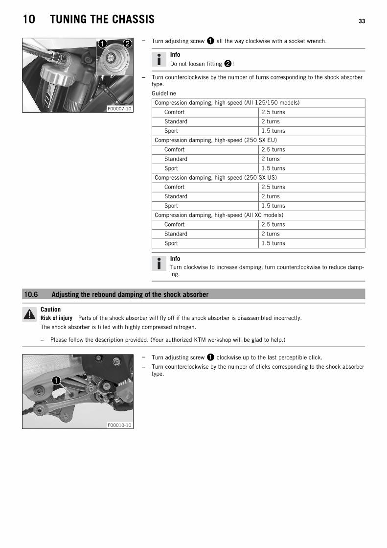
F00007-10
– Turn adjusting screw all the way clockwise with a socket wrench.
InfoDo not loosen fitting!
– Turn counterclockwise by the number of turns corresponding to the shock absorbertype.
Guideline
Compression damping, high-speed (All 125/150 models)
Comfort 2.5 turns
Standard 2 turns
Sport 1.5 turns
Compression damping, high-speed (250 SX EU)
Comfort 2.5 turns
Standard 2 turns
Sport 1.5 turns
Compression damping, high-speed (250 SX US)
Comfort 2.5 turns
Standard 2 turns
Sport 1.5 turns
Compression damping, high-speed (All XC models)
Comfort 2.5 turns
Standard 2 turns
Sport 1.5 turns
InfoTurn clockwise to increase damping; turn counterclockwise to reduce damp-ing.
10.6 Adjusting the rebound damping of the shock absorber
CautionRisk of injury Parts of the shock absorber will fly off if the shock absorber is disassembled incorrectly.
The shock absorber is filled with highly compressed nitrogen.
– Please follow the description provided. (Your authorized KTM workshop will be glad to help.)
F00010-10
– Turn adjusting screw clockwise up to the last perceptible click.
– Turn counterclockwise by the number of clicks corresponding to the shock absorbertype.

10 TUNING THE CHASSIS 34
Guideline
Rebound damping (All 125/150 models)
Comfort 17 clicks
Standard 15 clicks
Sport 13 clicks
Rebound damping (250 SX EU)
Comfort 17 clicks
Standard 15 clicks
Sport 13 clicks
Rebound damping (250 SX US)
Comfort 17 clicks
Standard 15 clicks
Sport 13 clicks
Rebound damping (All XC models)
Comfort 17 clicks
Standard 15 clicks
Sport 13 clicks
InfoTurn clockwise to increase damping; turn counterclockwise to reduce damp-ing.
10.7 Measuring the rear wheel dimension unloadedPreparatory work– Raise the motorcycle with a lift stand. ( p. 42)
402415-10
Main work– Position the sag gauge in the rear axle and measure the distance to marking SAG on
the rear fender.
Sag gauge (00029090000)
Pin for sag gauge (00029990010)
– Note down the value as dimension.
Finishing work– Remove the motorcycle from the lift stand. ( p. 42)
10 TUNING THE CHASSIS 35
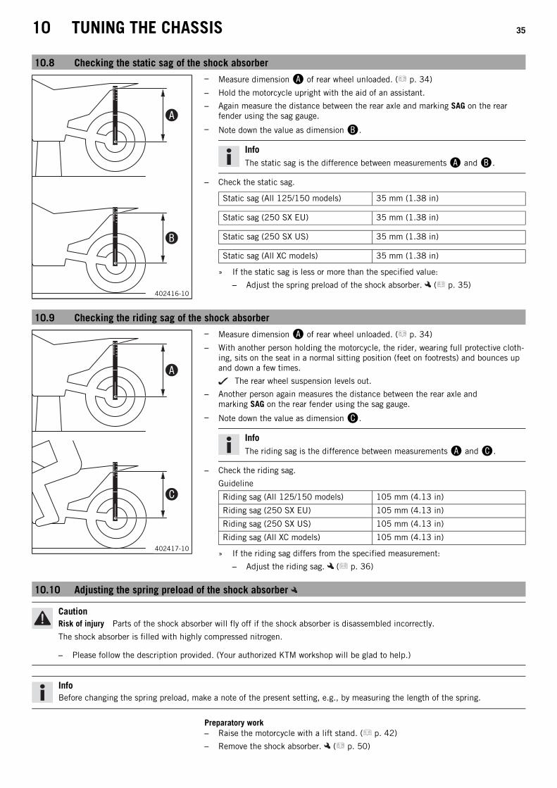
10.8 Checking the static sag of the shock absorber
402416-10
– Measure dimension of rear wheel unloaded. ( p. 34)
– Hold the motorcycle upright with the aid of an assistant.
– Again measure the distance between the rear axle and marking SAG on the rearfender using the sag gauge.
– Note down the value as dimension.
InfoThe static sag is the difference between measurements and.
– Check the static sag.
Static sag (All 125/150 models) 35 mm (1.38 in)
Static sag (250 SX EU) 35 mm (1.38 in)
Static sag (250 SX US) 35 mm (1.38 in)
Static sag (All XC models) 35 mm (1.38 in)
» If the static sag is less or more than the specified value:
– Adjust the spring preload of the shock absorber. ( p. 35)
10.9 Checking the riding sag of the shock absorber
402417-10
– Measure dimension of rear wheel unloaded. ( p. 34)
– With another person holding the motorcycle, the rider, wearing full protective cloth-ing, sits on the seat in a normal sitting position (feet on footrests) and bounces upand down a few times.
The rear wheel suspension levels out.
– Another person again measures the distance between the rear axle andmarking SAG on the rear fender using the sag gauge.
– Note down the value as dimension.
InfoThe riding sag is the difference between measurements and.
– Check the riding sag.
Guideline
Riding sag (All 125/150 models) 105 mm (4.13 in)
Riding sag (250 SX EU) 105 mm (4.13 in)
Riding sag (250 SX US) 105 mm (4.13 in)
Riding sag (All XC models) 105 mm (4.13 in)
» If the riding sag differs from the specified measurement:
– Adjust the riding sag. ( p. 36)
10.10 Adjusting the spring preload of the shock absorber
CautionRisk of injury Parts of the shock absorber will fly off if the shock absorber is disassembled incorrectly.
The shock absorber is filled with highly compressed nitrogen.
– Please follow the description provided. (Your authorized KTM workshop will be glad to help.)
InfoBefore changing the spring preload, make a note of the present setting, e.g., by measuring the length of the spring.
Preparatory work– Raise the motorcycle with a lift stand. ( p. 42)
– Remove the shock absorber. ( p. 50)

10 TUNING THE CHASSIS 36
– After removing the shock absorber, clean it thoroughly.
M01133-10
Main work– Loosen screw.
– Turn adjusting ring until the spring is no longer under tension.
Hook wrench (T106S)
– Measure the overall spring length while the spring is not under tension.
– Tighten the spring by turning adjusting ring to measurement.
Guideline
Spring preload (All 125/150 models) 6 mm (0.24 in)
Spring preload (250 SX EU) 8 mm (0.31 in)
Spring preload (250 SX US) 5 mm (0.2 in)
Spring preload (All XC models) 7 mm (0.28 in)
InfoDepending on the static sag and/or the riding sag, it may be necessary toincrease or decrease the spring preload.
– Tighten screw.
Guideline
Screw, shock absorber adjusting ring M5 5 Nm (3.7 lbf ft)
Finishing work– Install the shock absorber. ( p. 51)
– Remove the motorcycle from the lift stand. ( p. 42)
10.11 Adjusting the riding sagPreparatory work– Raise the motorcycle with a lift stand. ( p. 42)
– Remove the shock absorber. ( p. 50)
– After removing the shock absorber, clean it thoroughly.
B00292-10
Main work– Choose and mount a suitable spring.

10 TUNING THE CHASSIS 37
Guideline
Spring rate (All 125/150 models)
Weight of rider: 65… 75 kg (143…165 lb.)
36 N/mm (206 lb/in)
Weight of rider: 75… 85 kg (165…187 lb.)
39 N/mm (223 lb/in)
Weight of rider: 85… 95 kg (187…209 lb.)
42 N/mm (240 lb/in)
Spring rate (250 SX EU)
Weight of rider: 65… 75 kg (143…165 lb.)
39 N/mm (223 lb/in)
Weight of rider: 75… 85 kg (165…187 lb.)
42 N/mm (240 lb/in)
Weight of rider: 85… 95 kg (187…209 lb.)
45 N/mm (257 lb/in)
Spring rate (250 SX US)
Weight of rider: 65… 75 kg (143…165 lb.)
39 N/mm (223 lb/in)
Weight of rider: 75… 85 kg (165…187 lb.)
42 N/mm (240 lb/in)
Weight of rider: 85… 95 kg (187…209 lb.)
45 N/mm (257 lb/in)
Spring rate (All XC models)
Weight of rider: 65… 75 kg (143…165 lb.)
39 N/mm (223 lb/in)
Weight of rider: 75… 85 kg (165…187 lb.)
42 N/mm (240 lb/in)
Weight of rider: 85… 95 kg (187…209 lb.)
45 N/mm (257 lb/in)
InfoThe spring rate is shown on the outside of the spring.
Finishing work– Install the shock absorber. ( p. 51)
– Remove the motorcycle from the lift stand. ( p. 42)
– Check the static sag of the shock absorber. ( p. 35)
– Check the riding sag of the shock absorber. ( p. 35)
– Adjust the rebound damping of the shock absorber. ( p. 33)
10.12 Checking the basic setting of the fork
InfoFor various reasons, no exact riding sag can be determined for the fork.
401000-01
– Smaller differences in the rider's weight can be compensated for by the fork airpressure.
– However, if the fork frequently bottoms out (hard end stop on compression), thefork air pressure must be increased, within the specified values, to avoid damage tothe fork and frame.
– If the fork feels unusually hard after extended periods of operation, the fork legsneed to be bled.

10 TUNING THE CHASSIS 38
10.13 Adjusting the fork air pressure
WarningDanger of accident Modifications to the suspension setting may seriously alter the handling characteristic.
Extreme modifications to the suspension setting may cause a serious deterioration in the handling characteristic and overloadcomponents.
– Only make adjustments within the recommended range.
– Ride slowly to start with after making adjustments to get the feel of the new handling characteristic.
InfoCheck or adjust the air pressure under the same conditions at the earliest 5 minutes after switching off the engine.The air suspension is located in the left fork leg. The pressure and rebound damping is located in the right fork leg.
Preparatory work– Raise the motorcycle with a lift stand. ( p. 42)
K00461-10
Main work– Remove protection cap.
– Push fork pump together fully.
Fork pump (79412966000)
InfoThe fork pump is included as part of the motorcycle's separate enclosure.
– Connect the fork pump to the left fork leg.
The fork pump indicator switches on automatically.
A little air escapes from the fork leg when connecting.
InfoThis is due to the volume of the hose and not due to a defect in the forkpump or the fork.Read the accompanying KTM PowerParts instructions.
– Adjust the air pressure as specified.
Guideline
Air pressure (All 125/150 models) 8.2 bar (119 psi)
Air pressure (All 250 SX models) 10.2 bar (148 psi)
Air pressure (All XC models) 9.6 bar (139 psi)
Gradual changing of the air pressure insteps of
0.2 bar (3 psi)
Minimum air pressure 7 bar (102 psi)
Maximum air pressure 15 bar (218 psi)
InfoNever set the air pressure to a value outside the stated range.
– Disconnect the fork pump from the left fork leg.
When disconnecting, excess pressure will escape from the hose – the fork legitself does not lose any air.
The fork pump indicator switches off automatically after 80 seconds.
– Mount the protection cap.
Finishing work– Remove the motorcycle from the lift stand. ( p. 42)

10 TUNING THE CHASSIS 39
10.14 Adjusting the compression damping of the fork
InfoThe hydraulic compression damping determines the fork suspension behavior.
F00008-10
– Turn adjusting screw clockwise all the way.
InfoAdjusting screw is located at the upper end of the right fork leg.
– Turn counterclockwise by the number of clicks corresponding to the fork type.
Guideline
Compression damping (All 125/150 models)
Comfort 15 clicks
Standard 12 clicks
Sport 9 clicks
Compression damping (All 250 SX models)
Comfort 15 clicks
Standard 12 clicks
Sport 9 clicks
Compression damping (All XC models)
Comfort 15 clicks
Standard 12 clicks
Sport 10 clicks
InfoTurn clockwise to increase damping; turn counterclockwise to reduce damp-ing.
10.15 Adjusting the rebound damping of the fork
InfoThe hydraulic rebound damping determines the fork suspension behavior.
M01100-10
– Remove protection cap.
– Turn adjusting screw clockwise all the way.
InfoThe adjusting screw is located at the lower end of the right fork leg.
– Turn counterclockwise by the number of clicks corresponding to the fork type.
Guideline
Rebound damping (All 125/150 models)
Comfort 20 clicks
Standard 17 clicks
Sport 14 clicks
Rebound damping (All 250 SX models)
Comfort 20 clicks
Standard 17 clicks
Sport 14 clicks
Rebound damping (All XC models)
Comfort 15 clicks
Standard 12 clicks
Sport 10 clicks

10 TUNING THE CHASSIS 40
InfoTurn clockwise to increase damping; turn counterclockwise to reduce damp-ing.
– Mount protection cap.
10.16 Handlebar position
H01188-10
The holes on the handlebar supports are placed at a distance of from the center.
Hole distance A 3.5 mm (0.138 in)
The handlebar can be mounted in 2 different positions. In this way, the handlebar canbe mounted in the most comfortable position for the rider.
10.17 Adjusting the handlebar position
WarningDanger of accidents A repaired handlebar poses a safety risk.
If the handlebar is bent or straightened, the material becomes fatigued. The handlebar may break as a result.
– Change the handlebar if the handlebar is damaged or bent.
Preparatory work– Remove the handlebar cushion.
H01189-10
Main work– Remove screws. Remove the handlebar clamp. Remove the handlebar and lay it
to one side.
InfoCover the components to protect them against damage.Do not kink the cables and lines.
– Remove screws. Take off handlebar supports.
– Position rubber bushings and push through nuts from below.
– Place the handlebar supports in the required position.
InfoThe handlebar supports are longer and higher on one side.Position the left and right handlebar supports evenly.
– Mount and tighten screws.
Guideline
Screw, handlebar support M10 40 Nm(29.5 lbf ft)
Loctite® 243™
– Position the handlebar.
InfoMake sure the cables and wiring are positioned correctly.
– Position the handlebar clamp.
– Mount screws but do not tighten yet.
– First bolt the handlebar clamp with screws onto the longer, higher side of thehandlebar supports so that both parts touch.
Guideline
Screw, handlebar clamp M8 20 Nm(14.8 lbf ft)

10 TUNING THE CHASSIS 41
– Tighten screws evenly.
Guideline
Screw, handlebar clamp M8 20 Nm(14.8 lbf ft)
Finishing work– Mount the handlebar cushion.

11 SERVICE WORK ON THE CHASSIS 42
11.1 Raising the motorcycle with a lift stand
NoteMaterial damage The vehicle may be damaged by incorrect procedure when parking.
Significant damage may be caused if the vehicle rolls away or falls over.The components for parking the vehicle are designed only for the weight of the vehicle.
– Park the vehicle on a firm and level surface.
– Ensure that nobody sits on the vehicle when the vehicle is parked on a stand.
401942-01
– Raise the motorcycle at the frame underneath the engine.
Lift stand (78129955100)
Neither wheel is in contact with the ground.
– Secure the motorcycle against falling over.
11.2 Removing the motorcycle from the lift stand
NoteMaterial damage The vehicle may be damaged by incorrect procedure when parking.
Significant damage may be caused if the vehicle rolls away or falls over.The components for parking the vehicle are designed only for the weight of the vehicle.
– Park the vehicle on a firm and level surface.
– Ensure that nobody sits on the vehicle when the vehicle is parked on a stand.
0011
402001-10
(All SX models)– Remove the motorcycle from the lift stand.
– Remove the lift stand.
– To park the motorcycle, insert plug-in stand into the left side of the wheelspindle.
InfoRemove the plug-in stand before riding.
401943-10
(All XC models)– Remove the motorcycle from the lift stand.
– Remove the lift stand.
– To park the motorcycle, press side stand to the ground with your foot andlean the motorcycle on it.
InfoWhile riding, the side stand must be folded up and secured with therubber band.

11 SERVICE WORK ON THE CHASSIS 43
11.3 Bleeding the fork legsPreparatory work– Raise the motorcycle with a lift stand. ( p. 42)
H01182-12
Main work– Release bleeder screws.
Any excess pressure escapes from the interior of the fork.
– Tighten the bleeder screws.
Finishing work– Remove the motorcycle from the lift stand. ( p. 42)
11.4 Cleaning the dust boots of the fork legsPreparatory work– Raise the motorcycle with a lift stand. ( p. 42)
– Remove the fork protector. ( p. 44)
M01134-10
Main work– Push dust boots of both fork legs downward.
InfoThe dust boots remove dust and coarse dirt particles from the inside forktubes. Over time, dirt can accumulate behind the dust boots. If this dirt isnot removed, the oil seals behind can start to leak.
WarningDanger of accidents Oil or grease on the brake discs reduces the brakingeffect.
– Always keep the brake discs free of oil and grease.
– Clean the brake discs with brake cleaner when necessary.
– Clean and oil the dust boots and inner fork tubes of both fork legs.
Universal oil spray ( p. 129)
– Press the dust boots back into their normal position.
– Remove excess oil.
Finishing work– Install the fork protector. ( p. 45)
– Remove the motorcycle from the lift stand. ( p. 42)
11.5 Removing the fork legsPreparatory work– Raise the motorcycle with a lift stand. ( p. 42)
– Remove the front wheel. ( p. 76)
K00462-10
Main work– Remove screws and take off the clamp.
– Remove screws and take off the brake caliper.
– Allow the brake caliper and brake line to hang tension-free to the side.
InfoDo not activate the hand brake lever while the front wheel is removed.

11 SERVICE WORK ON THE CHASSIS 44
F00011-10
– Unscrew screws. Take out the left fork leg.
– Unscrew screws. Take out the right fork leg.
11.6 Installing the fork legs
H01182-10
Main work– Position the fork legs.
Bleeder screw of the right fork leg is positioned to the front.
Valve of the left fork leg faces the front.
InfoGrooves are milled into the side of the upper end of the fork legs. The sec-ond milled groove (from the top) must be flush with the top edge of theupper triple clamp.The air suspension is located in the left fork leg. The pressure and rebounddamping is located in the right fork leg.
F00011-11
– Tighten screws.
Guideline
Screw, top triple clamp M8 17 Nm(12.5 lbf ft)
– Tighten screws.
Guideline
Screw, bottom triple clamp M8 12 Nm (8.9 lbf ft)
K00462-11
– Position the brake caliper. Mount and tighten screws.
Guideline
Screw, front brake caliper M8 25 Nm(18.4 lbf ft)
Loctite® 243™
– Position the brake line and clamp. Mount and tighten screws.
Finishing work– Install the front wheel. ( p. 76)
11.7 Removing the fork protector
F00024-10
– Remove screws. Remove the clamp.
– Remove screws. Take off the left fork protector.
– Remove screws. Take off the right fork protector.

11 SERVICE WORK ON THE CHASSIS 45
11.8 Installing the fork protector
F00024-11
– Position the fork protection on the left fork leg. Mount and tighten screws.
Guideline
Remaining screws, chassis M6 10 Nm (7.4 lbf ft)
– Position the brake line and clamp. Mount and tighten screws.
– Position the fork protector on the right fork leg. Mount and tighten screws.
Guideline
Remaining screws, chassis M6 10 Nm (7.4 lbf ft)
11.9 Removing the lower triple clampPreparatory work– Raise the motorcycle with a lift stand. ( p. 42)
– Remove the front wheel. ( p. 76)
– Remove the fork legs. ( p. 43)
– Remove the start number plate. ( p. 49)
– Remove the front fender. ( p. 49)
– Remove the handlebar cushion.
K00463-10
Main work– Remove screw.
– Remove screw.
– Pull off the upper triple clamp with the handlebar and hang to the side.
InfoProtect the components against damage by covering them.Do not kink the cables and lines.
M01117-10
– Remove O-ring. Remove protective ring.
– Take off the lower triple clamp with the steering stem.
– Remove the upper steering head bearing.

11 SERVICE WORK ON THE CHASSIS 46
11.10 Installing the lower triple clamp
102146-10
Main work– Clean the bearing and sealing elements, check for damage, and grease.
High viscosity grease ( p. 129)
– Insert the lower triple clamp with the steering stem. Mount the upper steering headbearing.
– Check whether upper steering head seal is correctly positioned.
– Slide on protective ring and O-ring.
K00464-10
– Position the upper triple clamp with the handlebar.
– Mount screw but do not tighten yet.
H01182-11
– Position the fork legs.
Bleeder screw of the right fork leg is positioned to the front.
Valve of the left fork leg faces the front.
InfoThe air suspension AER valve is located in the left fork leg.Grooves are milled into the side of the upper end of the fork legs. The sec-ond milled groove (from the top) must be flush with the top edge of theupper triple clamp.
K00473-10
– Tighten screws.
Guideline
Screw, bottom triple clamp M8 12 Nm (8.9 lbf ft)
K00465-10
– Tighten screw.
Guideline
Screw, top steering head M20x1.5 12 Nm (8.9 lbf ft)

11 SERVICE WORK ON THE CHASSIS 47
F00028-10
– Mount and tighten screw.
Guideline
Screw, top steering stem M8 20 Nm(14.8 lbf ft)
Loctite® 243™
K00473-11
– Tighten screws.
Guideline
Screw, top triple clamp M8 17 Nm(12.5 lbf ft)
K00462-12
– Position the brake caliper. Mount and tighten screws.
Guideline
Screw, front brake caliper M8 25 Nm(18.4 lbf ft)
Loctite® 243™
– Position the brake line and clamp. Mount and tighten screws .
Finishing work– Check that the wiring harness, throttle cables, and brake and clutch lines can move
freely and are routed correctly.
– Install the front fender. ( p. 49)
– Install the front wheel. ( p. 76)
– Check the play of the steering head bearing. ( p. 47)
– Remove the motorcycle from the lift stand. ( p. 42)
– Install the start number plate. ( p. 49)
– Mount the handlebar cushion.
11.11 Checking the play of the steering head bearing
WarningDanger of accidents Incorrect steering head bearing play impairs the handling characteristic and damages components.
– Correct incorrect steering head bearing play immediately. (Your authorized KTM workshop will be glad to help.)
InfoIf the bike is ridden with play in the steering head bearing, the bearing and the bearing seats in the frame can become dam-aged over time.
Preparatory work– Raise the motorcycle with a lift stand. ( p. 42)

11 SERVICE WORK ON THE CHASSIS 48
H01167-01
Main work– Move the handlebar to the straight-ahead position. Move the fork legs to and fro in
the direction of travel.
No play should be noticeable in the steering head bearing.
» If there is noticeable play present:
– Adjust the steering head bearing play. ( p. 48)
– Move the handlebar to and fro over the entire steering range.
The handlebar must be able to move easily over the entire steering range. Thereshould be no perceptible detent positions.
» If detent positions are noticeable:
– Adjust the steering head bearing play. ( p. 48)
– Check the steering head bearing and replace if required.
Finishing work– Remove the motorcycle from the lift stand. ( p. 42)
11.12 Adjusting the steering head bearing playPreparatory work– Raise the motorcycle with a lift stand. ( p. 42)
– Remove the handlebar cushion.
K00471-10
Main work– Loosen screws.
– Remove screw.
– Loosen and retighten screw.
Guideline
Screw, top steering head M20x1.5 12 Nm (8.9 lbf ft)
– Using a plastic hammer, tap lightly on the upper triple clamp to avoid stresses.
– Tighten screws.
Guideline
Screw, top triple clamp M8 17 Nm(12.5 lbf ft)
– Mount and tighten screw.
Guideline
Screw, top steering stem M8 20 Nm(14.8 lbf ft)
Loctite® 243™
Finishing work– Check the play of the steering head bearing. ( p. 47)
– Remove the motorcycle from the lift stand. ( p. 42)
– Mount the handlebar cushion.
11.13 Greasing the steering head bearing
800010-10
– Remove the lower triple clamp. ( p. 45)
– Install the lower triple clamp. ( p. 46)
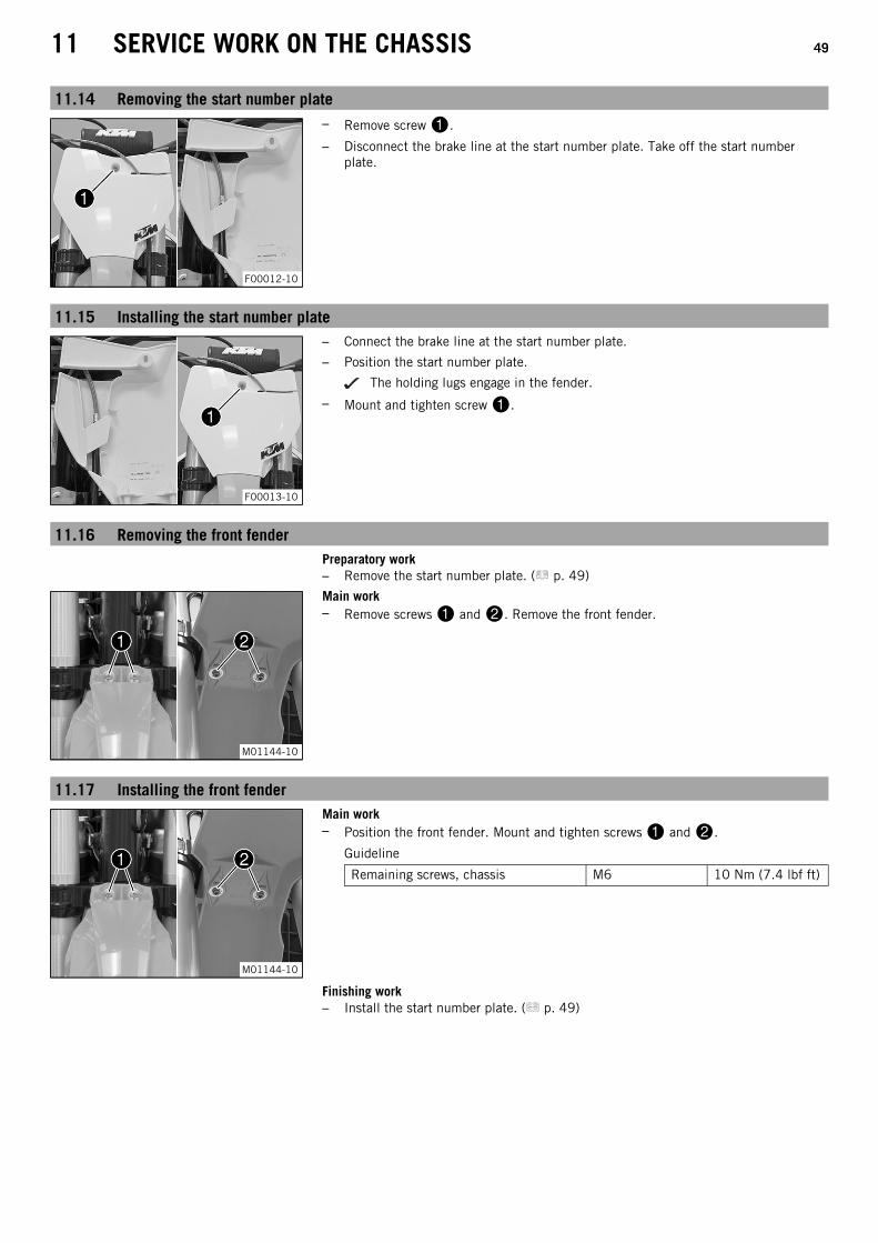
11 SERVICE WORK ON THE CHASSIS 49
11.14 Removing the start number plate
F00012-10
– Remove screw.
– Disconnect the brake line at the start number plate. Take off the start numberplate.
11.15 Installing the start number plate
F00013-10
– Connect the brake line at the start number plate.
– Position the start number plate.
The holding lugs engage in the fender.
– Mount and tighten screw.
11.16 Removing the front fenderPreparatory work– Remove the start number plate. ( p. 49)
M01144-10
Main work– Remove screws and. Remove the front fender.
11.17 Installing the front fender
M01144-10
Main work– Position the front fender. Mount and tighten screws and.
Guideline
Remaining screws, chassis M6 10 Nm (7.4 lbf ft)
Finishing work– Install the start number plate. ( p. 49)

11 SERVICE WORK ON THE CHASSIS 50
11.18 Removing the shock absorberPreparatory work– Raise the motorcycle with a lift stand. ( p. 42)
K00512-10
Main work– Remove screws with the washers and remove screws.
– Remove the cable ties and remove the frame protectors on the left and right.
F00015-10
– Remove screw.
– Remove fitting.
InfoRaise the wheel slightly to be able to remove the screws more easily.
F00025-10
– Press angle lever toward the rear.
– Press linkage lever downward.
F00026-10
– Remove screws and pull foot brake cylinder off the push rod.
M01149-01
– Remove the connecting link of the chain.
– Take off the chain.

11 SERVICE WORK ON THE CHASSIS 51
F00027-10
– Remove nut and pull out the swingarm pivot.
– Push the swingarm back and secure it against falling over.
F00029-10
– Hold the shock absorber and remove screw.
F00030-01
– Remove the shock absorber carefully at the bottom.
11.19 Installing the shock absorber
F00030-02
Main work– Carefully position the shock absorber into the vehicle from the bottom.
F00029-11
– Mount and tighten screw.
Guideline
Screw, top shock absorber M10 60 Nm(44.3 lbf ft)
Loctite® 2701™
F00035-10
– Position the swingarm and mount the swingarm pivot.
InfoPay attention to flat area.
– Mount and tighten nut.
Guideline
Nut, swingarm pivot M16x1.5 100 Nm(73.8 lbf ft)

11 SERVICE WORK ON THE CHASSIS 52
M01149-01
– Mount the chain.
– Connect the chain with the connecting link.
Guideline
The closed side of the chain joint lock must face in the direction of travel.
F00036-10
– Position the foot brake cylinder.
Push rod engages in the foot brake cylinder.
The dust boot is correctly positioned.
– Mount and tighten screws.
Guideline
Remaining screws, chassis M6 10 Nm (7.4 lbf ft)
K00474-10
– Position the angle lever and linkage lever.
– Mount and tighten fitting.
Guideline
Nut, linkage lever to angle lever M14x1.5 80 Nm (59 lbf ft)
InfoPay attention to flat area.
– Mount and tighten screw.
Guideline
Screw, bottom shockabsorber
M10 60 Nm(44.3 lbf ft)
Loctite® 2701™
InfoRaise the wheel slightly to be able to mount the screw more easily.
K00512-11
– Position the frame protectors on the left and right.
– Mount and tighten screws with the washers and mount and tighten screws.
Guideline
Screw, frame protector M5 3 Nm (2.2 lbf ft)
– Mount the cable tie(s).
Finishing work– Remove the motorcycle from the lift stand. ( p. 42)
11.20 Removing the seat
F00017-10
– Remove screws.
– Raise the rear of the seat, pull the seat back, and lift it off.

11 SERVICE WORK ON THE CHASSIS 53
11.21 Mounting the seat
F00016-10
– Mount the front of the seat on the collar bushing of the fuel tank, lower the seat atthe rear, and push the seat forward.
– Make sure that the seat is correctly locked in.
F00017-10
– Mount and tighten screws.
Guideline
Remaining screws, chassis M6 10 Nm (7.4 lbf ft)
11.22 Removing the air filter box cover
F00018-10
ConditionThe air filter box cover is secured.
– Remove screw.
F00018-11
– Pull off the air filter box cover in area sideways and remove it toward the front.
11.23 Installing the air filter box cover
F00018-12
– Insert the air filter box cover in area and clip it into area.

11 SERVICE WORK ON THE CHASSIS 54
F00018-10
ConditionThe air filter box cover is secured.
– Mount and tighten screw.
Guideline
Screw, air filter box cover EJOT PT®
K60x20-Z3 Nm(2.2 lbf ft)
EJOT PT screw(0017060204)
11.24 Removing the air filter
NoteEngine damage Unfiltered intake air has a negative effect on the service life of the engine.
Dust and dirt will enter the engine without an air filter.
– Never start to use the vehicle without an air filter.
WarningEnvironmental hazard Hazardous substances cause environmental damage.
– Dispose of oils, grease, filters, fuel, cleaning agents, brake fluid, etc., correctly and in compliance with the applicable regu-lations.
Preparatory work– Remove the air filter box cover. ( p. 53)
F00019-10
Main work– Detach retaining tab. Remove air filter with air filter support.
– Take off air filter from air filter support.
11.25 Cleaning the air filter and air filter box
WarningEnvironmental hazard Hazardous substances cause environmental damage.
– Dispose of oils, grease, filters, fuel, cleaning agents, brake fluid, etc., correctly and in compliance with the applicable regu-lations.
InfoDo not clean the air filter with fuel or petroleum since these substances attack the foam.
Preparatory work– Remove the air filter box cover. ( p. 53)
– Remove the air filter. ( p. 54)
K00518-01
Main work– Wash the air filter thoroughly in special cleaning liquid and allow it to dry properly.
Air filter cleaner ( p. 129)
InfoOnly squeeze the air filter to dry it; never wring it out.
– Oil the dry air filter with a high quality filter oil.
Oil for foam air filter ( p. 129)

11 SERVICE WORK ON THE CHASSIS 55
– Clean the air filter box.
– Clean the intake flange and check it for damage and tightness.
Finishing work– Install the air filter. ( p. 55)
– Install the air filter box cover. ( p. 53)
11.26 Installing the air filter
102178-10
Main work– Mount the clean air filter on the air filter support.
– Grease the air filter in area.
Long-life grease ( p. 129)
F00031-10
– Insert the air filter and position the top retaining pin in bushing.
The air filter is correctly positioned.
– Secure the bottom retaining pin with holding tab.
InfoIf the air filter is not mounted correctly, dust and dirt may enter the engineand result in damage.
Finishing work– Install the air filter box cover. ( p. 53)
11.27 Securing the air filter box coverPreparatory work– Remove the air filter box cover. ( p. 53)
M01109-10
Main work– Drill a hole at marking.
Guideline
Diameter 6 mm (0.24 in)
Finishing work– Install the air filter box cover. ( p. 53)
11.28 Sealing the air filter boxPreparatory work– Remove the air filter box cover. ( p. 53)
S00847-10
Main work– Seal the air filter box in marked area.
Finishing work– Install the air filter box cover. ( p. 53)

11 SERVICE WORK ON THE CHASSIS 56
11.29 Removing the main silencer
WarningDanger of burns The exhaust system gets very hot when the vehicle is driven.
– Allow the exhaust system to cool down before performing any work on the vehicle.
F00020-10
– Remove screws with the washers.
– Pull off the main silencer from the manifold at rubber sleeve.
11.30 Installing the main silencer
F00022-10
– Position the main silencer with rubber sleeve.
– Mount and tighten screws with the washers.
Guideline
Remaining screws, chassis M6 10 Nm (7.4 lbf ft)
11.31 Changing the glass fiber yarn filling in the main silencer
WarningDanger of burns The exhaust system gets very hot when the vehicle is driven.
– Allow the exhaust system to cool down before performing any work on the vehicle.
InfoOver time, the fibers of the glass fiber yarn escape and the damper "burns" out.Not only is the noise level higher, the performance characteristic changes.
Preparatory work– Remove the main silencer. ( p. 56)

11 SERVICE WORK ON THE CHASSIS 57
402580-10
Main work– Remove screws. Pull out inner tube.
– Remove the glass fiber yarn filling from the inner tube.
– Clean the parts that need to be reinstalled and check for damage.
– Fit the new glass fiber yarn filling into the inner tube.
– Slide outer tube over the inner tube with the new glass fiber yarn filling.
– Mount and tighten all screws.
Guideline
Screws on the main silencer M5 7 Nm (5.2 lbf ft)
Finishing work– Install the main silencer. ( p. 56)
11.32 Removing the fuel tank
DangerFire hazard Fuel is highly flammable.
The fuel in the fuel tank expands when warm and can escape if overfilled.
– Do not refuel the vehicle in the vicinity of open flames or lit cigarettes.
– Switch off the engine for refueling.
– Make sure that no fuel is spilled; particularly not on hot parts of the vehicle.
– If any fuel is spilled, wipe it off immediately.
– Observe the specifications for refueling.
WarningDanger of poisoning Fuel is poisonous and a health hazard.
– Avoid skin, eye and clothing contact with fuel.
– Immediately consult a doctor if you swallow fuel.
– Do not inhale fuel vapors.
– In case of skin contact, rinse the affected area with plenty of water.
– Rinse the eyes thoroughly with water, and consult a doctor in case of fuel contact with the eyes.
– Change your clothing in case of fuel spills on them.
– Keep fuels correctly in a suitable canister, and out of the reach of children.
Preparatory work– Remove the seat. ( p. 52)
(All SX models)– Turn handle of the fuel tap to the OFF position.
(Figure K00510-10 p. 15)
(All XC models)– Turn handle of the fuel tap to the OFF position.
(Figure K00488-10 p. 15)

11 SERVICE WORK ON THE CHASSIS 58
F00021-10
Main work– Pull off the fuel hose.
InfoRemaining fuel may flow out of the fuel hose.
– Remove screws.
F00032-10
(All SX models)– Remove screw with the rubber bushing.
– Pull the fuel tank breather hose off the tank lid.
K00529-10
(All XC models)– Remove screw with the rubber bushing.
– Pull the fuel tank breather hose off the tank lid.
F00033-01
– Pull both spoilers off the sides of the radiator bracket and lift off the fuel tank.
11.33 Installing the fuel tank
DangerFire hazard Fuel is highly flammable.
The fuel in the fuel tank expands when warm and can escape if overfilled.
– Do not refuel the vehicle in the vicinity of open flames or lit cigarettes.
– Switch off the engine for refueling.
– Make sure that no fuel is spilled; particularly not on hot parts of the vehicle.
– If any fuel is spilled, wipe it off immediately.
– Observe the specifications for refueling.
WarningDanger of poisoning Fuel is poisonous and a health hazard.
– Avoid skin, eye and clothing contact with fuel.
– Immediately consult a doctor if you swallow fuel.
– Do not inhale fuel vapors.
– In case of skin contact, rinse the affected area with plenty of water.
– Rinse the eyes thoroughly with water, and consult a doctor in case of fuel contact with the eyes.
– Change your clothing in case of fuel spills on them.
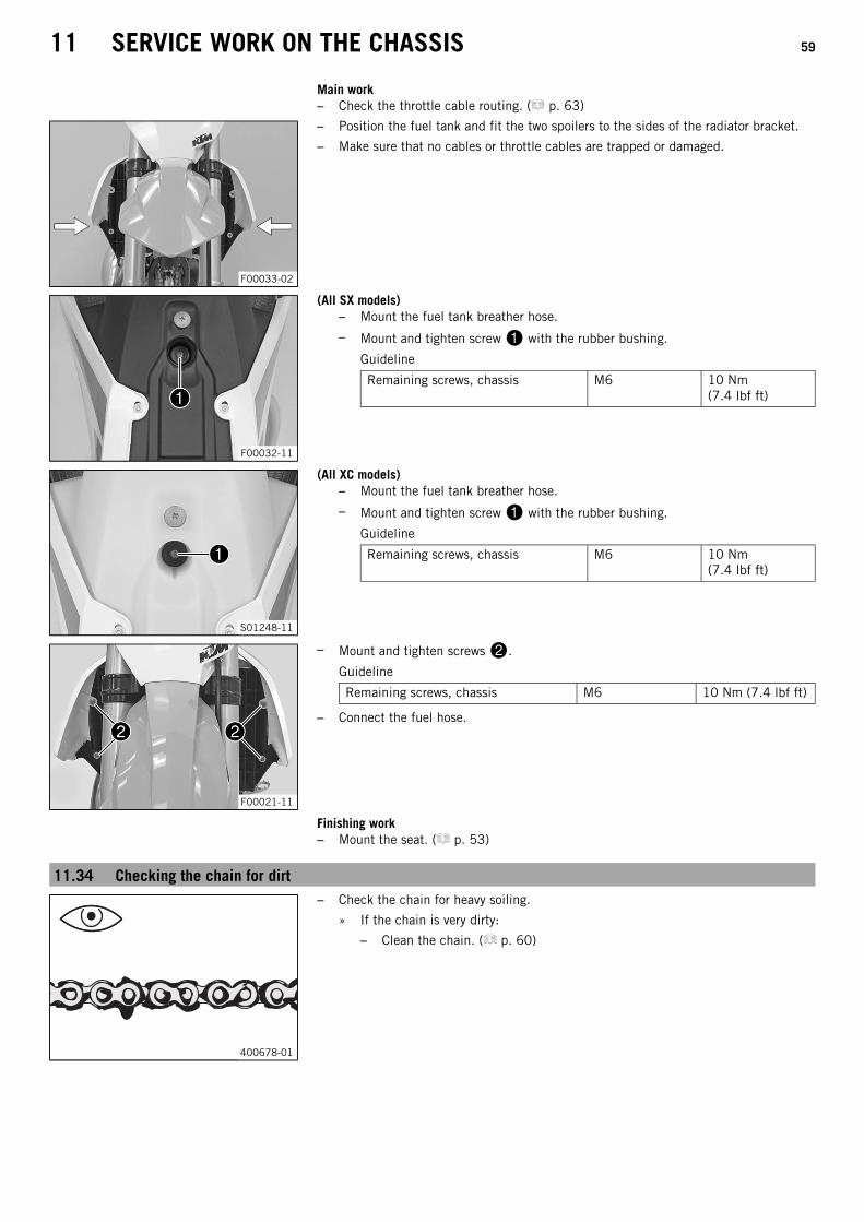
11 SERVICE WORK ON THE CHASSIS 59
Main work– Check the throttle cable routing. ( p. 63)
F00033-02
– Position the fuel tank and fit the two spoilers to the sides of the radiator bracket.
– Make sure that no cables or throttle cables are trapped or damaged.
F00032-11
(All SX models)– Mount the fuel tank breather hose.
– Mount and tighten screw with the rubber bushing.
Guideline
Remaining screws, chassis M6 10 Nm(7.4 lbf ft)
S01248-11
(All XC models)– Mount the fuel tank breather hose.
– Mount and tighten screw with the rubber bushing.
Guideline
Remaining screws, chassis M6 10 Nm(7.4 lbf ft)
F00021-11
– Mount and tighten screws.
Guideline
Remaining screws, chassis M6 10 Nm (7.4 lbf ft)
– Connect the fuel hose.
Finishing work– Mount the seat. ( p. 53)
11.34 Checking the chain for dirt
400678-01
– Check the chain for heavy soiling.
» If the chain is very dirty:
– Clean the chain. ( p. 60)
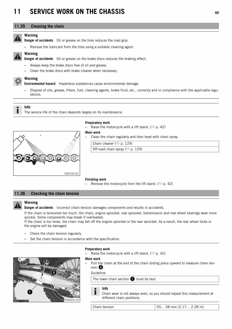
11 SERVICE WORK ON THE CHASSIS 60
11.35 Cleaning the chain
WarningDanger of accidents Oil or grease on the tires reduces the road grip.
– Remove the lubricant from the tires using a suitable cleaning agent.
WarningDanger of accidents Oil or grease on the brake discs reduces the braking effect.
– Always keep the brake discs free of oil and grease.
– Clean the brake discs with brake cleaner when necessary.
WarningEnvironmental hazard Hazardous substances cause environmental damage.
– Dispose of oils, grease, filters, fuel, cleaning agents, brake fluid, etc., correctly and in compliance with the applicable regu-lations.
InfoThe service life of the chain depends largely on its maintenance.
Preparatory work– Raise the motorcycle with a lift stand. ( p. 42)
400725-01
Main work– Clean the chain regularly and then treat with chain spray.
Chain cleaner ( p. 129)
Off-road chain spray ( p. 129)
Finishing work– Remove the motorcycle from the lift stand. ( p. 42)
11.36 Checking the chain tension
WarningDanger of accidents Incorrect chain tension damages components and results in accidents.
If the chain is tensioned too much, the chain, engine sprocket, rear sprocket, transmission and rear wheel bearings wear morequickly. Some components may break if overloaded.If the chain is too loose, the chain may fall off the engine sprocket or the rear sprocket. As a result, the rear wheel locks orthe engine will be damaged.
– Check the chain tension regularly.
– Set the chain tension in accordance with the specification.
Preparatory work– Raise the motorcycle with a lift stand. ( p. 42)
F00023-10
Main work– Pull the chain at the end of the chain sliding piece upward to measure chain ten-
sion.
Guideline
The lower chain section must be taut.
InfoChain wear is not always even, so you should repeat this measurement atdifferent chain positions.
Chain tension 55… 58 mm (2.17… 2.28 in)

11 SERVICE WORK ON THE CHASSIS 61
» If the chain tension does not meet the specification:
– Adjust the chain tension. ( p. 61)
Finishing work– Remove the motorcycle from the lift stand. ( p. 42)
11.37 Adjusting the chain tension
WarningDanger of accidents Incorrect chain tension damages components and results in accidents.
If the chain is tensioned too much, the chain, engine sprocket, rear sprocket, transmission and rear wheel bearings wear morequickly. Some components may break if overloaded.If the chain is too loose, the chain may fall off the engine sprocket or the rear sprocket. As a result, the rear wheel locks orthe engine will be damaged.
– Check the chain tension regularly.
– Set the chain tension in accordance with the specification.
Preparatory work– Raise the motorcycle with a lift stand. ( p. 42)
– Check the chain tension. ( p. 60)
H00016-10
Main work– Loosen nut.
– Loosen nuts.
– Adjust the chain tension by turning adjusting screws to the left and right.
Guideline
Chain tension 55… 58 mm (2.17… 2.28 in)
Turn adjusting screws on the left and right so that the markings on theleft and right chain adjusters are in the same position relative to referencemarks. The rear wheel is now correctly aligned.
– Tighten nuts.
– Make sure that chain adjusters are fitted correctly on adjusting screws.
– Tighten nut.
Guideline
Nut, rear wheel spindle M25x1.5 80 Nm (59 lbf ft)
InfoThe wide adjustment range of the chain adjusters (32 mm) enables differentsecondary ratios with the same chain length.Chain adjusters can be turned by 180°.
Finishing work– Remove the motorcycle from the lift stand. ( p. 42)
11.38 Checking the chain, rear sprocket, engine sprocket, and chain guidePreparatory work– Raise the motorcycle with a lift stand. ( p. 42)
400227-01
Main work– Shift the transmission to idle.
– Check the rear sprocket and engine sprocket for wear.
» If the rear sprocket and engine sprocket are worn:
– Change the drivetrain kit.
InfoThe engine sprocket, rear sprocket, and chain should always bereplaced together.

11 SERVICE WORK ON THE CHASSIS 62
400987-10
– Pull at the top part of the chain with the specified weight.
Guideline
Weight, chain wear measurement 10… 15 kg (22… 33 lb.)
– Measure distance of 18 chain rollers in the lower chain section.
InfoChain wear is not always even, so you should repeat this measurement atdifferent chain positions.
Maximum distance at the longestchain section
272 mm (10.71 in)
» If distance is greater than the specified measurement:
– Change the drivetrain kit.
InfoWhen a new chain is mounted, the rear sprocket and enginesprocket should also be changed.New chains wear out faster on old, worn sprockets.
M01166-10
– Check the chain sliding guard for wear.
» If the lower edge of the chain pins is in line with or below the chain slidingguard:
– Change the chain sliding guard.
– Check that the chain sliding guard is firmly seated.
» If the chain sliding guard is loose:
– Tighten the screws on the chain sliding guard.
Guideline
Screw, chain slidingguard
M6 6 Nm(4.4 lbf ft)
Loctite® 243™
S01250-01
– Check the chain sliding piece for wear.
» If the lower edge of the chain pins is in line with or below the chain slidingpiece:
– Change the chain sliding piece.
– Check that the chain sliding piece is firmly seated.
» If the chain sliding piece is loose:
– Tighten the screw on the chain sliding piece.
Guideline
Screw, chain sliding piece M8 15 Nm(11.1 lbf ft)

11 SERVICE WORK ON THE CHASSIS 63
402421-10
– Check the chain guide with a slide gauge for dimension.
Minimum thickness of the chainguide
6 mm (0.24 in)
» If the measured value is less than the specification:
– Change the chain guide.
102192-01
– Check that the chain guide is firmly seated.
» If the chain guide is loose:
– Tighten the screws on the chain guide.
Guideline
Remaining screws, chassis M6 10 Nm(7.4 lbf ft)
Remaining nuts, chassis M6 10 Nm(7.4 lbf ft)
Finishing work– Remove the motorcycle from the lift stand. ( p. 42)
11.39 Checking the frame
K00519-01
– Check the frame for cracks and deformation.
» If the frame exhibits cracks or deformation due to a mechanical impact:
– Change the frame.
InfoAlways replace a frame that has been damaged due to a mechanicalimpact. Repair of the frame is not authorized by KTM.
11.40 Checking the swingarm
500285-01
– Check the swingarm for damage, cracking, and deformation.
» If the swingarm shows signs of damage, cracking, or deformation:
– Change the swingarm.
InfoAlways change a damaged swingarm. Repair of the swingarm is notauthorized by KTM.
11.41 Checking the throttle cable routing
WarningDanger of accidents The throttle cable may slip out of the guide if routed incorrectly.
The throttle slide will then no longer be closed and the speed can no longer be controlled.
– Make sure that the throttle cable routing and the play in throttle cable complies with the specification.
Preparatory work– Remove the seat. ( p. 52)
(All SX models)– Turn handle of the fuel tap to the OFF position.
(Figure K00510-10 p. 15)

11 SERVICE WORK ON THE CHASSIS 64
(All XC models)– Turn handle of the fuel tap to the OFF position.
(Figure K00488-10 p. 15)
– Remove the fuel tank. ( p. 57)
F00034-01
Main work– Check the throttle cable routing.
The throttle cable must be routed along the back of the handlebar, to the right ofthe frame, above the fuel tank bracket, and to the carburetor. The throttle cablemust be fixed on the fuel tank bracket with a rubber band.
» If the throttle cable is not routed as specified:
– Correct the throttle cable routing.
Finishing work– Install the fuel tank. ( p. 58)
– Mount the seat. ( p. 53)
11.42 Checking the rubber grip
401197-01
– Check the rubber grips on the handlebar for damage, wear, and looseness.
InfoThe rubber grips are vulcanized onto a sleeve on the left and onto the han-dle tube of the throttle grip on the right. The left sleeve is clamped onto thehandlebar.The rubber grip can only be replaced with the sleeve or the throttle tube.
» If a rubber grip is damaged or worn:
– Change the rubber grip.
102245-10
– Check that screw is firmly seated.
Guideline
Screw, fixed grip M4 5 Nm(3.7 lbf ft)
Loctite® 243™
Diamond must be located at the top.
11.43 Adjusting basic position of clutch lever
F00009-11
– Adjust the basic setting of the clutch lever to your hand size by turning adjustingscrew.
InfoTurn the adjusting screw counterclockwise to decrease the distance betweenthe clutch lever and the handlebar.Turn the adjusting screw clockwise to increase the distance between theclutch lever and the handlebar.The range of adjustment is limited.Turn the adjusting screw by hand only, and do not apply any force.Do not make any adjustments while riding.

11 SERVICE WORK ON THE CHASSIS 65
11.44 Checking/correcting the fluid level of the hydraulic clutch
WarningSkin irritation Brake fluid causes skin irritation.
– Keep brake fluid out of the reach of children.
– Wear suitable protective clothing and safety glasses.
– Do not allow brake fluid to come into contact with the skin, the eyes or clothing.
– Consult a doctor immediately if brake fluid has been swallowed.
– Rinse the affected area with plenty of water in the event of contact with the skin.
– Rinse eyes thoroughly with water immediately and consult a doctor if brake fluid comes into contact with the eyes.
– If brake fluid spills on to your clothing, change the clothing.
InfoThe fluid level rises with increasing wear of the clutch facing discs.Never use DOT 5 brake fluid. It is silicone-based and purple in color. Oil seals and clutch lines are not designed for DOT 5brake fluid.Avoid contact between brake fluid and painted parts. Brake fluid attacks paint.Only use clean brake fluid from a sealed container.
H01330-10
– Move the clutch fluid reservoir mounted on the handlebar to a horizontal position.
– Remove screws.
– Remove cover with membrane.
– Check the fluid level.
Fluid level below container rim 4 mm (0.16 in)
» If the fluid level does not meet specifications:
– Correct the fluid level of the hydraulic clutch.
Brake fluid DOT 4 / DOT 5.1 ( p. 127)
– Position the cover with the membrane. Mount and tighten the screws.
InfoClean up overflowed or spilled brake fluid immediately with water.
11.45 Changing the hydraulic clutch fluid
WarningSkin irritation Brake fluid causes skin irritation.
– Keep brake fluid out of the reach of children.
– Wear suitable protective clothing and safety glasses.
– Do not allow brake fluid to come into contact with the skin, the eyes or clothing.
– Consult a doctor immediately if brake fluid has been swallowed.
– Rinse the affected area with plenty of water in the event of contact with the skin.
– Rinse eyes thoroughly with water immediately and consult a doctor if brake fluid comes into contact with the eyes.
– If brake fluid spills on to your clothing, change the clothing.
WarningEnvironmental hazard Hazardous substances cause environmental damage.
– Dispose of oils, grease, filters, fuel, cleaning agents, brake fluid, etc., correctly and in compliance with the applicable regu-lations.
InfoNever use DOT 5 brake fluid. It is silicone-based and purple in color. Oil seals and clutch lines are not designed for DOT 5brake fluid.Avoid contact between brake fluid and painted parts. Brake fluid attacks paint.Only use clean brake fluid from a sealed container.

11 SERVICE WORK ON THE CHASSIS 66
H01330-10
– Move the clutch fluid reservoir mounted on the handlebar to a horizontal position.
– Remove screws.
– Remove cover with membrane.
K00520-10
– Fill bleeding syringe with the appropriate hydraulic fluid.
Bleed syringe (50329050000)
Brake fluid DOT 4 / DOT 5.1 ( p. 127)
– On the clutch slave cylinder, remove bleeder screw and mount bleedingsyringe.
L01223-10
– Now inject the liquid into the system until it emerges from the drill hole of themaster cylinder without bubbles.
– Now and then, extract fluid from the master cylinder reservoir to prevent overflow.
– Remove the bleeding syringe. Mount and tighten screws bleeder screw.
– Correct the fluid level of the hydraulic clutch.
Guideline
Fluid level below container rim 4 mm (0.16 in)
– Position the cover with the membrane. Mount and tighten the screws.
InfoClean up overflowed or spilled brake fluid immediately with water.

12 BRAKE SYSTEM 67
12.1 Checking the free travel of the hand brake lever
WarningDanger of accidents The brake system fails in the event of overheating.
If there is no free travel on the hand brake lever, pressure builds up on the front brake circuit.
– Set the free travel on the hand brake lever in accordance with the specification.
K00453-11
– Push the hand brake lever forward and check free travel.
Free travel of hand brake lever ≥ 3 mm (≥ 0.12 in)
» If the free travel does not meet specifications:
– Adjust the basic position of the hand brake lever. ( p. 67)
12.2 Adjusting the basic position of the hand brake lever
K00453-10
– Check the free travel of the hand brake lever. ( p. 67)
– Adjust the basic position of the hand brake lever to your hand size by turningadjusting screw.
InfoTurn the adjusting screw clockwise to increase the distance between thehand brake lever and the handlebar.Turn the adjusting screw counterclockwise to decrease the distance betweenthe hand brake lever and the handlebar.The range of adjustment is limited.Only turn the adjusting screw by hand, and do not use force.Do not make any adjustments while riding.
12.3 Checking the brake discs
WarningDanger of accidents Worn-out brake discs reduce the braking effect.
– Make sure that worn-out brake discs are replaced immediately. (Your authorized KTM workshop will be glad to help.)
H00938-10
– Check the thickness of the front and rear brake discs at multiple points on eachbrake disc to ensure it is at least thickness.
InfoWear reduces the thickness of the brake disc around the area used by thebrake linings.
Brake discs - wear limit
Front 2.5 mm (0.098 in)
Rear 3.5 mm (0.138 in)
» If the brake disc thickness is less than the specified value:
– Change the front brake discs.
– Change the rear brake disc.
– Check the front and rear brake discs for damage, cracking, and deformation.
» If the brake disc exhibits damage, cracking, or deformation:
– Change the front brake discs.
– Change the rear brake disc.

12 BRAKE SYSTEM 68
12.4 Checking the front brake fluid level
WarningDanger of accidents An insufficient brake fluid level will cause the brake system to fail.
If the brake fluid level drops below the specified marking or the specified value, the brake system is leaking or the brake lin-ings are worn down.
– Check the brake system and do not continue riding until the problem is eliminated. (Your authorized KTM workshop will beglad to help.)
WarningDanger of accidents Old brake fluid reduces the braking effect.
– Make sure that brake fluid for the front and rear brake is changed in accordance with the service schedule. (Your autho-rized KTM workshop will be glad to help.)
Preparatory work– Check the front brake linings. ( p. 69)
H01332-10
Main work– Move the brake fluid reservoir mounted on the handlebar to a horizontal position.
– Check the brake fluid level in the viewer.
» If the brake fluid level is below the marking:
– Add front brake fluid. ( p. 68)
12.5 Adding front brake fluid
WarningDanger of accidents An insufficient brake fluid level will cause the brake system to fail.
If the brake fluid level drops below the specified marking or the specified value, the brake system is leaking or the brake lin-ings are worn down.
– Check the brake system and do not continue riding until the problem is eliminated. (Your authorized KTM workshop will beglad to help.)
WarningSkin irritation Brake fluid causes skin irritation.
– Keep brake fluid out of the reach of children.
– Wear suitable protective clothing and safety glasses.
– Do not allow brake fluid to come into contact with the skin, the eyes or clothing.
– Consult a doctor immediately if brake fluid has been swallowed.
– Rinse the affected area with plenty of water in the event of contact with the skin.
– Rinse eyes thoroughly with water immediately and consult a doctor if brake fluid comes into contact with the eyes.
– If brake fluid spills on to your clothing, change the clothing.
WarningDanger of accidents Old brake fluid reduces the braking effect.
– Make sure that brake fluid for the front and rear brake is changed in accordance with the service schedule. (Your autho-rized KTM workshop will be glad to help.)
WarningEnvironmental hazard Hazardous substances cause environmental damage.
– Dispose of oils, grease, filters, fuel, cleaning agents, brake fluid, etc., correctly and in compliance with the applicable regu-lations.

12 BRAKE SYSTEM 69
InfoNever use DOT 5 brake fluid. It is silicone-based and purple in color. Oil seals and brake lines are not designed for DOT 5brake fluid.Avoid contact between brake fluid and painted parts. Brake fluid attacks paint.Only use clean brake fluid from a sealed container.
Preparatory work– Check the front brake linings. ( p. 69)
K00470-10
Main work– Move the brake fluid reservoir mounted on the handlebar to a horizontal position.
– Remove screws.
– Remove cover with membrane.
– Add brake fluid to level.
Guideline
Level (brake fluid level below reser-voir rim)
5 mm (0.2 in)
Brake fluid DOT 4 / DOT 5.1 ( p. 127)
– Position the cover with the membrane. Mount and tighten the screws.
InfoClean up overflowed or spilled brake fluid immediately with water.
12.6 Checking the front brake linings
WarningDanger of accidents Worn-out brake linings reduce the braking effect.
– Ensure that worn-out brake linings are replaced immediately. (Your authorized KTM workshop will be glad to help.)
H01333-10
– Check the brake linings for minimum thickness.
Minimum thickness ≥ 1 mm (≥ 0.04 in)
» If the minimum thickness is less than specified:
– Change the front brake linings. ( p. 69)
– Check the brake linings for damage and cracking.
» If damage or cracking is visible:
– Change the front brake linings. ( p. 69)
12.7 Changing the front brake linings
WarningDanger of accidents Incorrect maintenance will cause the brake system to fail.
– Ensure that service work and repairs are performed professionally. (Your authorized KTM workshop will be glad to help.)

12 BRAKE SYSTEM 70
WarningSkin irritation Brake fluid causes skin irritation.
– Keep brake fluid out of the reach of children.
– Wear suitable protective clothing and safety glasses.
– Do not allow brake fluid to come into contact with the skin, the eyes or clothing.
– Consult a doctor immediately if brake fluid has been swallowed.
– Rinse the affected area with plenty of water in the event of contact with the skin.
– Rinse eyes thoroughly with water immediately and consult a doctor if brake fluid comes into contact with the eyes.
– If brake fluid spills on to your clothing, change the clothing.
WarningDanger of accidents Old brake fluid reduces the braking effect.
– Make sure that brake fluid for the front and rear brake is changed in accordance with the service schedule. (Your autho-rized KTM workshop will be glad to help.)
WarningDanger of accidents Oil or grease on the brake discs reduces the braking effect.
– Always keep the brake discs free of oil and grease.
– Clean the brake discs with brake cleaner when necessary.
WarningDanger of accidents Brake linings which have not been approved alter the braking efficiency.
Not all brake linings are tested and approved for KTM motorcycles. The structure and friction coefficient of the brake linings,and thus their brake power, may vary greatly from that of original brake linings.If brake linings are used that differ from the original equipment, compliance with the original homologation is not guaranteed.In this case, the vehicle no longer corresponds to its condition at delivery and the warranty shall be void.
– Only use brake linings approved and recommended by KTM.
WarningEnvironmental hazard Hazardous substances cause environmental damage.
– Dispose of oils, grease, filters, fuel, cleaning agents, brake fluid, etc., correctly and in compliance with the applicable regu-lations.
InfoNever use DOT 5 brake fluid. It is silicone-based and purple in color. Oil seals and brake lines are not designed for DOT 5brake fluid.Avoid contact between brake fluid and painted parts. Brake fluid attacks paint.Only use clean brake fluid from a sealed container.
K00469-10
– Move the brake fluid reservoir mounted on the handlebar to a horizontal position.
– Remove screws.
– Remove cover with membrane.
– Manually press the brake caliper toward the brake disc to push back the brake pis-tons. Ensure that brake fluid does not flow out of the brake fluid reservoir, if neces-sary extract excess.
InfoMake sure that you do not press the brake caliper against the spokes whenpushing back the brake pistons.
101737-10
– Remove cotter pins, pull out pin, and remove the brake linings.
– Clean the brake caliper and brake caliper support.

12 BRAKE SYSTEM 71
100397-01
– Check that leaf spring in the brake caliper and sliding plate in the brakecaliper support are seated correctly.
101738-01
– Insert the new brake linings, insert the pin, and mount the cotter pins.
InfoAlways change the brake linings in pairs.
– Operate the hand brake lever repeatedly until the brake linings are in contact withthe brake disc and there is a pressure point.
K00521-10
– Correct the brake fluid quantity to level.
Guideline
Level (brake fluid level below reser-voir rim)
5 mm (0.2 in)
Brake fluid DOT 4 / DOT 5.1 ( p. 127)
– Position the cover with the membrane. Mount and tighten the screws.
InfoClean up overflowed or spilled brake fluid immediately with water.
12.8 Checking the free travel of foot brake lever
WarningDanger of accidents The brake system fails in the event of overheating.
If there is no free travel on the foot brake lever, pressure builds up in the brake system on the rear brake.
– Set the free travel on the foot brake lever in accordance with the specification.
402026-10
– Disconnect spring.
– Move the foot brake lever back and forth between the end stop and the contact tothe foot brake cylinder piston and check free travel.
Guideline
Free travel at foot brake lever 3… 5 mm (0.12… 0.2 in)
» If the free travel does not meet specifications:
– Adjust the basic position of the foot brake lever. ( p. 71)
– Reconnect spring.
12.9 Adjusting the basic position of the foot brake lever
WarningDanger of accidents The brake system fails in the event of overheating.
If there is no free travel on the foot brake lever, pressure builds up in the brake system on the rear brake.
– Set the free travel on the foot brake lever in accordance with the specification.

12 BRAKE SYSTEM 72
K00523-10
– Detach spring.
– Loosen nut and, with push rod, turn it back until you have maximum freetravel.
– To adjust the basic position of the foot brake lever to individual requirements,loosen nut and turn screw accordingly.
InfoThe range of adjustment is limited.
– Turn push rod accordingly until you have free travel. If necessary, adjustthe basic position of the foot brake lever.
Guideline
Free travel at foot brake lever 3… 5 mm (0.12… 0.2 in)
– Hold screw and tighten nut.
Guideline
Nut, foot brake lever stop M8 20 Nm(14.8 lbf ft)
– Hold push rod and tighten nut.
Guideline
Remaining nuts, chassis M6 10 Nm (7.4 lbf ft)
– Attach spring.
12.10 Checking the rear brake fluid level
WarningDanger of accidents An insufficient brake fluid level will cause the brake system to fail.
If the brake fluid level drops below the specified marking or the specified value, the brake system is leaking or the brake lin-ings are worn down.
– Check the brake system and do not continue riding until the problem is eliminated. (Your authorized KTM workshop will beglad to help.)
WarningDanger of accidents Old brake fluid reduces the braking effect.
– Make sure that brake fluid for the front and rear brake is changed in accordance with the service schedule. (Your autho-rized KTM workshop will be glad to help.)
Preparatory work– Check the rear brake linings. ( p. 73)
C00924-10
Main work– Stand the vehicle upright.
– Check the brake fluid level in level viewer.
» If the brake fluid has dropped below marking:
– Add rear brake fluid. ( p. 73)

12 BRAKE SYSTEM 73
12.11 Adding rear brake fluid
WarningDanger of accidents An insufficient brake fluid level will cause the brake system to fail.
If the brake fluid level drops below the specified marking or the specified value, the brake system is leaking or the brake lin-ings are worn down.
– Check the brake system and do not continue riding until the problem is eliminated. (Your authorized KTM workshop will beglad to help.)
WarningSkin irritation Brake fluid causes skin irritation.
– Keep brake fluid out of the reach of children.
– Wear suitable protective clothing and safety glasses.
– Do not allow brake fluid to come into contact with the skin, the eyes or clothing.
– Consult a doctor immediately if brake fluid has been swallowed.
– Rinse the affected area with plenty of water in the event of contact with the skin.
– Rinse eyes thoroughly with water immediately and consult a doctor if brake fluid comes into contact with the eyes.
– If brake fluid spills on to your clothing, change the clothing.
WarningDanger of accidents Old brake fluid reduces the braking effect.
– Make sure that brake fluid for the front and rear brake is changed in accordance with the service schedule. (Your autho-rized KTM workshop will be glad to help.)
WarningEnvironmental hazard Hazardous substances cause environmental damage.
– Dispose of oils, grease, filters, fuel, cleaning agents, brake fluid, etc., correctly and in compliance with the applicable regu-lations.
InfoNever use DOT 5 brake fluid. It is silicone-based and purple in color. Oil seals and brake lines are not designed for DOT 5brake fluid.Avoid contact between brake fluid and painted parts. Brake fluid attacks paint.Only use clean brake fluid from a sealed container.
Preparatory work– Check the rear brake linings. ( p. 73)
H01335-10
Main work– Stand the vehicle upright.
– Remove screw cap with membrane and the O-ring.
– Add brake fluid to level.
Brake fluid DOT 4 / DOT 5.1 ( p. 127)
– Mount the screw cap with the membrane and the O-ring.
InfoClean up overflowed or spilled brake fluid immediately with water.
12.12 Checking the rear brake linings
WarningDanger of accidents Worn-out brake linings reduce the braking effect.
– Ensure that worn-out brake linings are replaced immediately. (Your authorized KTM workshop will be glad to help.)

12 BRAKE SYSTEM 74
M01180-10
– Check the brake linings for minimum thickness.
Minimum thickness ≥ 1 mm (≥ 0.04 in)
» If the minimum thickness is less than specified:
– Change the rear brake linings. ( p. 74)
– Check the brake linings for damage and cracking.
» If damage or cracking is visible:
– Change the rear brake linings. ( p. 74)
12.13 Changing the rear brake linings
WarningDanger of accidents Incorrect maintenance will cause the brake system to fail.
– Ensure that service work and repairs are performed professionally. (Your authorized KTM workshop will be glad to help.)
WarningSkin irritation Brake fluid causes skin irritation.
– Keep brake fluid out of the reach of children.
– Wear suitable protective clothing and safety glasses.
– Do not allow brake fluid to come into contact with the skin, the eyes or clothing.
– Consult a doctor immediately if brake fluid has been swallowed.
– Rinse the affected area with plenty of water in the event of contact with the skin.
– Rinse eyes thoroughly with water immediately and consult a doctor if brake fluid comes into contact with the eyes.
– If brake fluid spills on to your clothing, change the clothing.
WarningDanger of accidents Old brake fluid reduces the braking effect.
– Make sure that brake fluid for the front and rear brake is changed in accordance with the service schedule. (Your autho-rized KTM workshop will be glad to help.)
WarningEnvironmental hazard Hazardous substances cause environmental damage.
– Dispose of oils, grease, filters, fuel, cleaning agents, brake fluid, etc., correctly and in compliance with the applicable regu-lations.
InfoNever use DOT 5 brake fluid. It is silicone-based and purple in color. Oil seals and brake lines are not designed for DOT 5brake fluid.Avoid contact between brake fluid and painted parts. Brake fluid attacks paint.Only use clean brake fluid from a sealed container.
H01336-10
– Stand the vehicle upright.
– Remove screw cap with membrane and the O-ring.

12 BRAKE SYSTEM 75
101740-10
– Manually press the brake caliper to the brake disc to push back the brake piston.Ensure that brake fluid does not flow out of the brake fluid reservoir, extracting itby suction if it does.
InfoMake sure when pushing back the brake piston that you do not press thebrake caliper against the spokes.
– Remove cotter pins, pull out pin, and remove the brake linings.
– Clean the brake caliper and brake caliper support.
101741-10
– Check that leaf spring in the brake caliper and sliding plate in the brakecaliper support are seated correctly.
InfoThe arrow on the leaf spring points in the rotation direction of the brakedisc.
M01181-10
– Insert the new brake linings, insert pin, and mount cotter pins.
InfoAlways change the brake linings in pairs.Make sure that decoupling plate is mounted on the piston side brakelining.
– Operate the foot brake lever repeatedly until the brake linings are in contact withthe brake disc and there is a pressure point.
H01335-10
– Add brake fluid to level.
Brake fluid DOT 4 / DOT 5.1 ( p. 127)
– Mount and tighten screw cap with membrane and the O-ring.
InfoClean up overflowed or spilled brake fluid immediately with water.

13 WHEELS, TIRES 76
13.1 Removing the front wheelPreparatory work– Raise the motorcycle with a lift stand. ( p. 42)
H01337-10
Main work– Press the brake caliper onto the brake disc by hand in order to push back the brake
pistons.
InfoMake sure that you do not press the brake caliper against the spokes whenpushing back the brake pistons.
K00454-10
– Loosen screw by several rotations.
– Loosen screws.
– Press on screw to push the wheel spindle out of the axle clamp.
– Remove screw.
H01340-10
WarningDanger of accidents Damaged brake discs reduce the braking effect.
– Always lay the wheel down in such a way that the brake disc is not dam-aged.
– Holding the front wheel, withdraw the wheel spindle. Take the front wheel out ofthe fork.
InfoDo not pull the hand brake lever when the front wheel is removed.
H00934-10
– Remove spacers.
13.2 Installing the front wheel
WarningDanger of accidents Oil or grease on the brake discs reduces the braking effect.
– Always keep the brake discs free of oil and grease.
– Clean the brake discs with brake cleaner when necessary.
H00935-10
– Check the wheel bearing for damage and wear.
» If the wheel bearing is damaged or worn:
– Change the front wheel bearing.
– Clean and grease shaft seal rings and contact surface of the spacers.
Long-life grease ( p. 129)
– Insert the spacers.

13 WHEELS, TIRES 77
K00454-11
– Lift the front wheel into the fork, position it, and insert the wheel spindle.
The brake linings are correctly positioned.
– Mount and tighten screw.
Guideline
Screw, front wheel spindle M20x1.5 35 Nm(25.8 lbf ft)
– Operate the hand brake lever several times until the brake linings are lying correctlyagainst the brake disc.
– Remove the motorcycle from the lift stand. ( p. 42)
– Operate the front brake and compress the fork a few times firmly.
The fork legs straighten.
– Tighten screws.
Guideline
Screw, fork stub M8 15 Nm(11.1 lbf ft)
13.3 Removing the rear wheelPreparatory work– Raise the motorcycle with a lift stand. ( p. 42)
H00027-10
Main work– Press the brake caliper onto the brake disc by hand in order to push back the brake
piston.
InfoMake sure when pushing back the brake piston that you do not press thebrake caliper against the spokes.
– Remove nut.
– Remove chain adjuster. Withdraw wheel spindle only enough to allow therear wheel to be pushed forward.
– Push the rear wheel forward as far as possible. Remove the chain from the rearsprocket.
InfoCover the components to protect them against damage.
WarningDanger of accidents Damaged brake discs reduce the braking effect.
– Always lay the wheel down in such a way that the brake disc is not dam-aged.
– Holding the rear wheel, withdraw the wheel spindle. Take the rear wheel out of theswingarm.
InfoDo not operate the foot brake lever when the rear wheel is removed.
H00936-10
– Remove spacers.

13 WHEELS, TIRES 78
13.4 Installing the rear wheel
WarningDanger of accidents Oil or grease on the brake discs reduces the braking effect.
– Always keep the brake discs free of oil and grease.
– Clean the brake discs with brake cleaner when necessary.
H00937-10
Main work– Check the wheel bearing for damage and wear.
» If the wheel bearing is damaged or worn:
– Change the rear wheel bearing.
– Clean and grease shaft seal rings and contact surface of the spacers.
Long-life grease ( p. 129)
– Insert the spacers.
H00006-10
– Position the rear wheel and insert wheel spindle.
The brake linings are correctly positioned.
– Mount the chain.
H00007-10
– Position chain adjuster. Mount nut, but do not tighten it yet.
– Make sure that chain adjusters are fitted correctly on adjusting screws.
– Check the chain tension. ( p. 60)
– Tighten nut.
Guideline
Nut, rear wheel spindle M25x1.5 80 Nm (59 lbf ft)
InfoThe wide adjustment range of the chain adjusters (32 mm (1.26 in))enables different secondary ratios with the same chain length.Chain adjusters can be turned by 180°.
– Operate the foot brake lever repeatedly until the brake linings are in contact withthe brake disc and there is a pressure point.
Finishing work– Remove the motorcycle from the lift stand. ( p. 42)

13 WHEELS, TIRES 79
13.5 Checking the tire condition
InfoOnly mount tires approved and/or recommended by KTM.Other tires could have a negative effect on handling characteristics.The type, condition, and air pressure of the tires all have a major impact on the handling of the motorcycle.The tires mounted on the front and rear wheels must have a similar profile.Worn tires have a negative effect on handling characteristics, especially on wet surfaces.
400602-10
– Check the front and rear tires for cuts, run-in objects, and other damage.
» If the tires have cuts, run-in objects, or other damage:
– Change the tires.
– Check the tread depth.
InfoAdhere to the legally required minimum tread depth.
Minimum tread depth ≥ 2 mm (≥ 0.08 in)
» If the tread depth is less than the minimum tread depth:
– Change the tires.
H01144-01
– Check the tire age.
InfoThe tire date of manufacture is usually contained in the tire label and isindicated by the last four digits of the DOT number. The first two digits indi-cate the week of manufacture and the last two digits the year of manufac-ture.KTM recommends that the tires be changed after 5 years at the latest,regardless of the actual state of wear.
» If the tires are more than 5 years old:
– Change the tires.
13.6 Checking the tire air pressure
InfoLow tire air pressure leads to abnormal wear and overheating of the tire.Correct tire air pressure ensures optimal riding comfort and maximum tire service life.
400695-01
– Remove the dust cap.
– Check the tire air pressure when the tires are cold.
Tire air pressure off road
Front 1.0 bar (15 psi)
Rear 1.0 bar (15 psi)
» If the tire pressure does not meet specifications:
– Correct the tire pressure.
– Mount the dust cap.
13.7 Checking spoke tension
WarningDanger of accidents Incorrectly tensioned spokes impair the handling characteristic and result in secondary damage.
The spokes break due to being overloaded if they are too tightly tensioned. If the tension in the spokes is too low, then lateraland radial run-out will form in the wheel. Other spokes will become looser as a result.
– Check spoke tension regularly, and in particular on a new vehicle. (Your authorized KTM workshop will be glad to help.)

13 WHEELS, TIRES 80
400694-01
– Strike each spoke briefly using a screwdriver blade.
InfoThe frequency of the sound depends on the spoke length and spoke diame-ter.If you hear different tone frequencies from different spokes of equal lengthand diameter, this is an indication of different spoke tensions.
You should hear a high note.
» If the spoke tension differs:
– Correct the spoke tension.
– Check the spoke torque.
Guideline
Spoke nipple, front wheel M4.5 6 Nm (4.4 lbf ft)
Spoke nipple, rear wheel M4.5 6 Nm (4.4 lbf ft)
Torque wrench with various accessories in set (58429094000)

14 ELECTRICAL SYSTEM 81
14.1 Removing the battery (All XC models)
WarningRisk of injury Batteries contain harmful substances.
– Keep batteries out of the reach of children.
– Keep sparks and open flames away from the batteries.
– Only charge batteries in well-ventilated rooms.
– Maintain a minimum clearance from inflammable materials when charging batteries.
Minimum clearance 1 m (3 ft)
– Do not charge deeply discharged batteries if charge is already below the minimum voltage.
Minimum voltage before the start of the charge 9 V
– Dispose of batteries with less than the minimum voltage correctly.
Preparatory work– Switch off all power consumers and switch off the engine.
– Remove the seat. ( p. 52)
F00138-10
Main work– Disconnect negative cable from the battery.
– Pull back positive terminal cover and disconnect the positive cable from thebattery.
– Remove screw.
– Pull holding bracket forward and remove battery toward the top.
14.2 Installing the battery (All XC models)
H00386-10
Main work– Position the battery in the battery compartment with the terminals facing forward,
and secure with holding bracket.
Battery (HJTZ5S-FP) ( p. 122)
– Mount and tighten screw.
Guideline
Remaining screws, chassis M6 10 Nm (7.4 lbf ft)
– Connect positive cable to the battery.
Guideline
Screw, battery terminal M5 2.5 Nm(1.84 lbf ft)
Contact disks must be mounted under screws and cable sockets withthe claws toward the battery terminal.
– Slide positive terminal cover over the positive terminal.
– Connect negative cable to the battery.
Guideline
Screw, battery terminal M5 2.5 Nm(1.84 lbf ft)
Finishing work– Mount the seat. ( p. 53)

14 ELECTRICAL SYSTEM 82
14.3 Recharging the battery (All XC models)
WarningRisk of injury Batteries contain harmful substances.
– Keep batteries out of the reach of children.
– Keep sparks and open flames away from the batteries.
– Only charge batteries in well-ventilated rooms.
– Maintain a minimum clearance from inflammable materials when charging batteries.
Minimum clearance 1 m (3 ft)
– Do not charge deeply discharged batteries if charge is already below the minimum voltage.
Minimum voltage before the start of the charge 9 V
– Dispose of batteries with less than the minimum voltage correctly.
WarningEnvironmental hazard The battery contains elements that are harmful to the environment.
– Do not dispose of batteries with the household waste. Dispose of a defective battery in an environmentally friendly manner.Give the battery to your authorized KTM dealer or dispose of it at a collection point for used batteries.
WarningEnvironmental hazard Hazardous substances cause environmental damage.
– Dispose of oils, grease, filters, fuel, cleaning agents, brake fluid, etc., correctly and in compliance with the applicable regu-lations.
InfoEven when there is no load on the battery, it discharges steadily.The charging level and the method of charging are very important for the service life of the battery.Rapid recharging with a high charging current shortens the service life of the battery.If the charging current, charging voltage, or charging time are exceeded, the battery will be destroyed.If the battery is depleted by repeated starting, the battery must be charged immediately.If the battery is left in a discharged state for an extended period, it will become over-discharged and sulfated, destroying thebattery.The battery is maintenance-free.
Preparatory work– Switch off all power consumers and switch off the engine.
– Remove the seat. ( p. 52)
– Remove the battery. ( p. 81)
S00863-10
Main work– Check the battery voltage.
» Battery voltage: < 9 V
– Do not charge the battery.
– Replace the battery and dispose of the old battery properly.
» If the specifications have been met:Battery voltage: ≥ 9 V
– Recharge the battery.
Guideline
The charging current, charging voltage, and charging time must not beexceeded.
Maximum charging voltage 14.4 V
Maximum charging current 3.0 A
Charge the battery regularly whenthe motorcycle is not in use
6 months
InfoNever remove cover.

14 ELECTRICAL SYSTEM 83
– Connect the battery charger to the battery. Switch on the battery charger.
Battery charger (58429074000)
In addition, this battery charger can be used to test the quiescent current, the startability of the battery, and the alternator. With this device, you cannot overchargethe battery. The charging time may be longer at low temperatures.
– Switch off the battery charger after charging and disconnect from the battery.
Finishing work– Install the battery. ( p. 81)
– Mount the seat. ( p. 53)
14.4 Changing the main fuse (All XC models)
WarningFire hazard Incorrect fuses overload the electrical system.
– Only use fuses with the required ampere value.
– Do not bypass or repair fuses.
InfoThe main fuse protects all power consumers of the vehicle. It is located in the starter relay housing under the seat.
Preparatory work– Switch off all power consumers and switch off the engine.
– Remove the seat. ( p. 52)
F00161-10
Main work– Pull starter relay from the holder.
F00162-10
– Take off protection caps.
– Remove the faulty main fuse.
InfoYou can recognize a defective fuse by a burned-out fuse wire.A spare fuse is located in the starter relay.
– Install a new main fuse.
Fuse (58011109110) ( p. 122)
– Check that the electrical system is functioning properly.
TipInsert a spare fuse so that it is available if needed.
– Mount the protection caps.
– Mount the starter relay onto the holder and route the cable.
Finishing work– Mount the seat. ( p. 53)
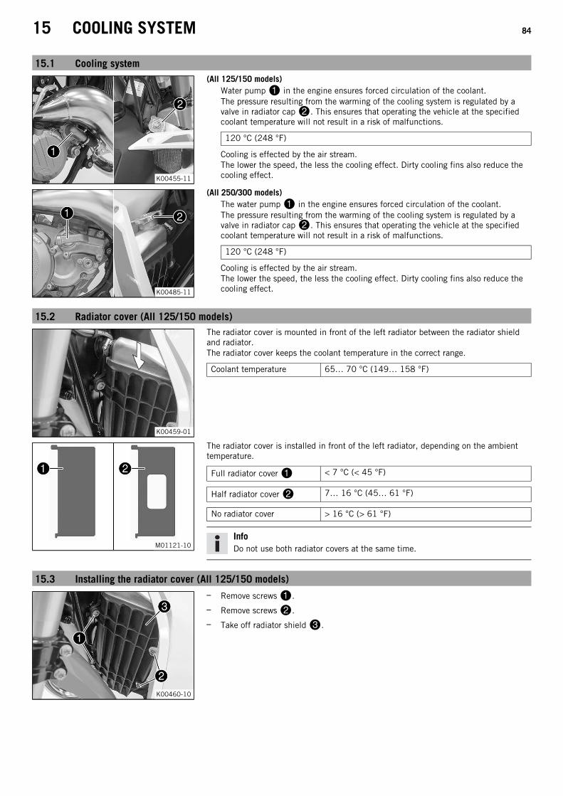
15 COOLING SYSTEM 84
15.1 Cooling system
K00455-11
(All 125/150 models)Water pump in the engine ensures forced circulation of the coolant.The pressure resulting from the warming of the cooling system is regulated by avalve in radiator cap. This ensures that operating the vehicle at the specifiedcoolant temperature will not result in a risk of malfunctions.
120 °C (248 °F)
Cooling is effected by the air stream.The lower the speed, the less the cooling effect. Dirty cooling fins also reduce thecooling effect.
K00485-11
(All 250/300 models)The water pump in the engine ensures forced circulation of the coolant.The pressure resulting from the warming of the cooling system is regulated by avalve in radiator cap. This ensures that operating the vehicle at the specifiedcoolant temperature will not result in a risk of malfunctions.
120 °C (248 °F)
Cooling is effected by the air stream.The lower the speed, the less the cooling effect. Dirty cooling fins also reduce thecooling effect.
15.2 Radiator cover (All 125/150 models)
K00459-01
The radiator cover is mounted in front of the left radiator between the radiator shieldand radiator.The radiator cover keeps the coolant temperature in the correct range.
Coolant temperature 65… 70 °C (149… 158 °F)
M01121-10
The radiator cover is installed in front of the left radiator, depending on the ambienttemperature.
Full radiator cover < 7 °C (< 45 °F)
Half radiator cover 7… 16 °C (45… 61 °F)
No radiator cover > 16 °C (> 61 °F)
InfoDo not use both radiator covers at the same time.
15.3 Installing the radiator cover (All 125/150 models)
K00460-10
– Remove screws.
– Remove screws.
– Take off radiator shield.

15 COOLING SYSTEM 85
H01341-10
– Position the matching radiator cover ( p. 84).
The larger catch is located at the top left.
InfoDo not use both radiator covers at the same time.
K00460-10
– Position radiator shield.
– Mount and tighten screws.
Guideline
Remaining screws, chassis M6 10 Nm (7.4 lbf ft)
– Mount and tighten screws.
Guideline
Remaining screws, chassis M6 10 Nm (7.4 lbf ft)
15.4 Removing the radiator cover (All 125/150 models)
K00460-10
– Remove screws.
– Remove screws.
– Take off radiator shield.
– Remove the radiator cover.
– Position radiator shield.
– Mount and tighten screws.
Guideline
Remaining screws, chassis M6 10 Nm (7.4 lbf ft)
– Mount and tighten screws.
Guideline
Remaining screws, chassis M6 10 Nm (7.4 lbf ft)
15.5 Checking the antifreeze and coolant level
WarningDanger of scalding During motorcycle operation, the coolant gets very hot and is under pressure.
– Do not open the radiator, the radiator hoses or other cooling system components if the engine or the cooling system are atoperating temperature.
– Allow the cooling system and the engine to cool down before you open the radiator, the radiator hoses or other componentsof the cooling system.
– In the event of scalding, rinse the area affected immediately with lukewarm water.
WarningDanger of poisoning Coolant is toxic and a health hazard.
– Keep coolant out of the reach of children.
– Do not allow coolant to come into contact with the skin, the eyes and clothing.
– Consult a doctor immediately if coolant is swallowed.
– Rinse the affected area immediately with plenty of water in the event of contact with the skin.
– Rinse eyes thoroughly with water and consult a doctor immediately if coolant gets into the eyes.
– Change clothing if coolant spills onto your clothing.
ConditionThe engine is cold.
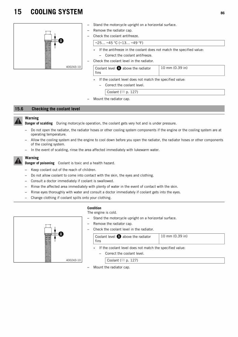
15 COOLING SYSTEM 86
400243-10
– Stand the motorcycle upright on a horizontal surface.
– Remove the radiator cap.
– Check the coolant antifreeze.
−25… −45 °C (−13… −49 °F)
» If the antifreeze in the coolant does not match the specified value:
– Correct the coolant antifreeze.
– Check the coolant level in the radiator.
Coolant level above the radiatorfins
10 mm (0.39 in)
» If the coolant level does not match the specified value:
– Correct the coolant level.
Coolant ( p. 127)
– Mount the radiator cap.
15.6 Checking the coolant level
WarningDanger of scalding During motorcycle operation, the coolant gets very hot and is under pressure.
– Do not open the radiator, the radiator hoses or other cooling system components if the engine or the cooling system are atoperating temperature.
– Allow the cooling system and the engine to cool down before you open the radiator, the radiator hoses or other componentsof the cooling system.
– In the event of scalding, rinse the area affected immediately with lukewarm water.
WarningDanger of poisoning Coolant is toxic and a health hazard.
– Keep coolant out of the reach of children.
– Do not allow coolant to come into contact with the skin, the eyes and clothing.
– Consult a doctor immediately if coolant is swallowed.
– Rinse the affected area immediately with plenty of water in the event of contact with the skin.
– Rinse eyes thoroughly with water and consult a doctor immediately if coolant gets into the eyes.
– Change clothing if coolant spills onto your clothing.
ConditionThe engine is cold.
400243-10
– Stand the motorcycle upright on a horizontal surface.
– Remove the radiator cap.
– Check the coolant level in the radiator.
Coolant level above the radiatorfins
10 mm (0.39 in)
» If the coolant level does not match the specified value:
– Correct the coolant level.
Coolant ( p. 127)
– Mount the radiator cap.

15 COOLING SYSTEM 87
15.7 Draining the coolant
WarningDanger of scalding During motorcycle operation, the coolant gets very hot and is under pressure.
– Do not open the radiator, the radiator hoses or other cooling system components if the engine or the cooling system are atoperating temperature.
– Allow the cooling system and the engine to cool down before you open the radiator, the radiator hoses or other componentsof the cooling system.
– In the event of scalding, rinse the area affected immediately with lukewarm water.
WarningDanger of poisoning Coolant is toxic and a health hazard.
– Keep coolant out of the reach of children.
– Do not allow coolant to come into contact with the skin, the eyes and clothing.
– Consult a doctor immediately if coolant is swallowed.
– Rinse the affected area immediately with plenty of water in the event of contact with the skin.
– Rinse eyes thoroughly with water and consult a doctor immediately if coolant gets into the eyes.
– Change clothing if coolant spills onto your clothing.
ConditionThe engine is cold.
– Position the motorcycle upright.
– Place a suitable container under the water pump cover.
K00455-10
(All 125/150 models)– Remove screw. Take off radiator cap.
– Completely drain the coolant.
– Mount and tighten screw with a new seal ring.
Guideline
Drain plug, water pump cover M6 8 Nm (5.9 lbf ft)
K00485-10
(All 250/300 models)– Remove screw. Take off radiator cap.
– Completely drain the coolant.
– Mount and tighten screw with a new seal ring.
Guideline
Screw, water pump cover (All 250 SXmodels)
M6 10 Nm(7.4 lbf ft)
Screw, water pump cover (All XCmodels)
M6 10 Nm(7.4 lbf ft)
15.8 Refilling with coolant
WarningDanger of poisoning Coolant is toxic and a health hazard.
– Keep coolant out of the reach of children.
– Do not allow coolant to come into contact with the skin, the eyes and clothing.
– Consult a doctor immediately if coolant is swallowed.
– Rinse the affected area immediately with plenty of water in the event of contact with the skin.
– Rinse eyes thoroughly with water and consult a doctor immediately if coolant gets into the eyes.
– Change clothing if coolant spills onto your clothing.
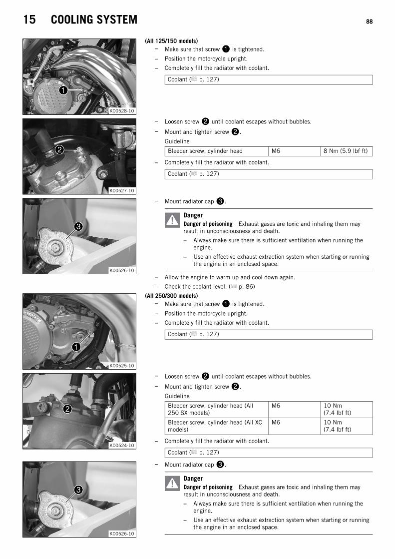
15 COOLING SYSTEM 88
K00528-10
(All 125/150 models)– Make sure that screw is tightened.
– Position the motorcycle upright.
– Completely fill the radiator with coolant.
Coolant ( p. 127)
K00527-10
– Loosen screw until coolant escapes without bubbles.
– Mount and tighten screw.
Guideline
Bleeder screw, cylinder head M6 8 Nm (5.9 lbf ft)
– Completely fill the radiator with coolant.
Coolant ( p. 127)
K00526-10
– Mount radiator cap.
DangerDanger of poisoning Exhaust gases are toxic and inhaling them mayresult in unconsciousness and death.
– Always make sure there is sufficient ventilation when running theengine.
– Use an effective exhaust extraction system when starting or runningthe engine in an enclosed space.
– Allow the engine to warm up and cool down again.
– Check the coolant level. ( p. 86)
K00525-10
(All 250/300 models)– Make sure that screw is tightened.
– Position the motorcycle upright.
– Completely fill the radiator with coolant.
Coolant ( p. 127)
K00524-10
– Loosen screw until coolant escapes without bubbles.
– Mount and tighten screw.
Guideline
Bleeder screw, cylinder head (All250 SX models)
M6 10 Nm(7.4 lbf ft)
Bleeder screw, cylinder head (All XCmodels)
M6 10 Nm(7.4 lbf ft)
– Completely fill the radiator with coolant.
Coolant ( p. 127)
K00526-10
– Mount radiator cap.
DangerDanger of poisoning Exhaust gases are toxic and inhaling them mayresult in unconsciousness and death.
– Always make sure there is sufficient ventilation when running theengine.
– Use an effective exhaust extraction system when starting or runningthe engine in an enclosed space.

15 COOLING SYSTEM 89
– Allow the engine to warm up and cool down again.
– Check the coolant level. ( p. 86)

16 TUNING THE ENGINE 90
16.1 Checking the play in the throttle cable
400192-11
– Check the throttle grip for smooth operation.
– Move the handlebar to the straight-ahead position. Move the throttle grip back andforth slightly to determine the play in throttle cable.
Play in throttle cable 2… 3 mm (0.08… 0.12 in)
» If the throttle cable play does not meet specifications:
– Adjust the play in the throttle cable. ( p. 90)
DangerDanger of poisoning Exhaust gases are toxic and inhaling them may resultin unconsciousness and death.
– Always make sure there is sufficient ventilation when running theengine.
– Use an effective exhaust extraction system when starting or running theengine in an enclosed space.
– Start the engine and let it run idle. Move the handlebar to and fro over the entiresteering range.
The idle speed must not change.
» If the idle speed changes:
– Adjust the play in the throttle cable. ( p. 90)
16.2 Adjusting the play in the throttle cable
InfoIf the correct routing of the throttle cable has already been secured, the fuel tank does not need to be removed.
Preparatory work– Remove the seat. ( p. 52)
(All SX models)– Turn handle of the fuel tap to the OFF position.
(Figure K00510-10 p. 15)
(All XC models)– Turn handle of the fuel tap to the OFF position.
(Figure K00488-10 p. 15)
– Remove the fuel tank. ( p. 57)
– Check the throttle cable routing. ( p. 63)
K00457-10
Main work– Move the handlebar to the straight-ahead position.
– Push back sleeve.
– Ensure that the throttle cable sleeve is pushed all the way into barrel adjuster.
– Loosen nut.
400192-11
– Turn barrel adjuster so that there is play in the throttle cable at the throttlegrip.
Guideline
Play in throttle cable 2… 3 mm (0.08… 0.12 in)
– Tighten nut.
– Slide on sleeve.

16 TUNING THE ENGINE 91
Finishing work– Check the throttle grip for smooth operation.
– Install the fuel tank. ( p. 58)
– Mount the seat. ( p. 53)
– Check the play in the throttle cable. ( p. 90)
16.3 Carburetor settingEffects of the carburetor setting
H01400-01
The different carburetor components must be tuned both to one another and for the use intended.
Main jet MJThe main jet MJ has the greatest influence with the throttle slide open (full throttle).If the insulator of a new spark plug is very light or white after a brief ride at full throttle, or if the engine knocks, a larger main jetneeds to be used. If the insulator is dark brown or sooty, a smaller main jet needs to be used.
Needle position POSThe needle position has the greatest influence in the mid throttle slide range.If the engine stutters when accelerating with a partially open throttle slide, the jet needle must be lowered. If the engine knocks whenaccelerating at the full power rpm range, the jet needle must be raised.
Cylindrical part of the needle CYLThe cylindrical part of the needle has the greatest influence when the throttle slide is almost closed.
Idling jet IJThe idling jet has the greatest influence in the low to mid throttle slide range.If the engine stutters when idling or accelerating with a partially open throttle slide, a smaller idling jet must be used. If the engineknocks in this power range, then a larger idling jet must be used.
Idle air adjusting screw open ASOThe idle air adjusting screw has the greatest influence during idling.

16 TUNING THE ENGINE 92
Influence of throttle slide adjustment
1/41/8
1/2
3/4
0
1
1/41/8
1/2
3/4
0
1
K00495-01
The idling jet has the greatest influence when the throttle slide is closed. The first cylindrical part of the needle and the clip positionhave only minimal influence.When the throttle slide is 1/8 open, the first cylindrical part of the needle, the idling jet and the clip position have the greatest influ-ence.
1/41/8
1/2
3/4
0
1
1/41/8
1/2
3/4
0
1
K00496-01
When the throttle slide is 1/4 open, the idling jet and the clip position have the greatest influence. The influence of the first cylindri-cal part of the needle is less.When the throttle slide is 1/2 open, the position of the needle has the greatest influence. The influence of the main jet and the idlingjet is only minimal.
1/41/8
1/2
3/4
0
1
1/41/8
1/2
3/4
0
1
K00497-01
When the throttle slide is 3/4 open, the influence of the main jet is greatest. The clip position and the idling jet have only minimalinfluence.When the throttle slide is fully open, the influence of the main jet is greatest. The clip position and the idling jet have only minimalinfluence.
Needle overviewThe jet needles available are shown in the following table.
402674-01
Column 2 corresponds to a needle in the standard position.Column 1 corresponds to a needle which is half a clip leaner.Column 3 corresponds to a needle which is half a clip richer.Column 4 specifies the diameter of the first cylindrical part of the needle. The smaller the diameter of the first cylindrical part of theneedle, the richer the carburation. The larger the diameter of the first cylindrical part of the needle, the leaner the carburation. Thefirst cylindrical part of the needle has the greatest influence in the lowest load adjustment.

16 TUNING THE ENGINE 93
InfoThe top right jet needle A3 corresponds to the richest setting of the carburetor, and the bottom left jet needle F1 correspondsto the leanest. The optimal carburetor tuning is shown under the respective model.
004400330055
00220011
B00075-10
Clip position
1... 5 Clip position from above
The five possible clip positions are shown here.The carburetor tuning depends on the defined ambient and operating conditions.
16.4 Carburetor – idle
K00486-10
The idle setting of the carburetor has a big influence on the starting behavior, stableidling, and the response to throttle opening. This means that an engine with a correctlyset idle speed is easier to start than if the idle speed is set wrongly.
InfoThe carburetor and its components are subject to increased wear caused byengine vibration. Wear can result in malfunctioning.
The factory setting for the carburetor is set for the following values.
(All 125/150 models)
Height above sea level 301… 750 m (988… 2,461 ft)
Ambient temperature 16… 24 °C (61… 75 °F)
Super unleaded (98 octane) mixed with 2-stroke engine oil (1:40) ( p. 128)
(All 250/300 models)
Height above sea level 301… 750 m (988… 2,461 ft)
Ambient temperature 6… 15 °C (43… 59 °F)
Super unleaded (95 octane) mixed with 2-stroke engine oil (1:60) ( p. 128)
The idle speed is adjusted with adjusting screw.The idle mixture is adjusted with idle air adjusting screw.
16.5 Carburetor – adjusting the idle speed
K00486-11
– Screw in idle air adjusting screw all the way and turn it to the specified basicposition.
InfoThe basic adjustment is shown under the respective model.
– Run the engine until warm.
Guideline
Warm-up time ≥ 5 min
DangerDanger of poisoning Exhaust gases are toxic and inhaling them may resultin unconsciousness and death.
– Always make sure there is sufficient ventilation when running theengine.
– Use an effective exhaust extraction system when starting or running theengine in an enclosed space.
– Adjust the idle speed with adjusting screw.
Guideline
Choke function deactivated – The choke lever is pushed in to the stop. ( p. 16)
Idle speed 1,400… 1,500 rpm

16 TUNING THE ENGINE 94
– Turn idle air adjusting screw slowly in a clockwise direction until the idle speedbegins to fall.
– Note the position and turn the idle air adjusting screw slowly counterclockwise untilthe idle speed again begins to fall.
– Adjust to the point between these two positions with the highest idle speed.
InfoIf there is a big engine speed rise, reduce the idle speed to a normal leveland repeat the above steps.If the procedure described here does not lead to satisfactory results, thecause may be a wrongly dimensioned idling jet.If you can turn the idle air adjusting screw to the end without any change ofengine speed, mount a smaller idling jet.After changing the jet, start from the beginning with the adjusting steps.Following extreme air temperature or altitude changes, adjust the idle speedagain.
16.6 Plug-in connector of ignition timing map adjustment
K00458-10
(All SX models)Plug-in connector of the ignition timing map adjustment is located on theframe under the fuel tank.
K00509-10
(All XC models)Plug-in connector of the ignition timing map adjustment is located on theframe under the fuel tank.
Possible states(All SX models)
• Soft – The plug-in connector of the ignition timing map adjustment is discon-nected to achieve better rideability.
• Performance – The plug-in connector of the ignition timing map adjustment isjoined to achieve higher performance.
(All XC models)• Soft – The plug-in connector of the ignition timing map adjustment is discon-
nected to achieve better rideability.• Performance – The plug-in connector of the ignition timing map adjustment is
joined to achieve higher performance.
16.7 Changing the ignition timing mapSwitch the ignition timing map from Performance to Soft
(All 125/150 models)– Disconnect plug-in connector of the ignition timing map adjustment. (Figure K00458-10 p. 94)
Soft – better rideability
(All 250/300 models)(All XC models)
– Disconnect plug-in connector of the ignition timing map adjustment. (Figure K00509-10 p. 94)
Soft – better rideability
Switch the ignition timing map from Soft to Performance(All 125/150 models)
– Join plug-in connector of the ignition timing map adjustment. (Figure K00458-10 p. 94)
Performance – better performance
(All 250/300 models)(All XC models)
– Join plug-in connector of the ignition timing map adjustment. (Figure K00509-10 p. 94)
Performance – better performance

16 TUNING THE ENGINE 95
16.8 Checking the basic position of the shift lever
InfoWhen driving, the shift lever must not touch the rider's boot when in the basic position.When the shift lever keeps touching the boot, the transmission will be subject to an excessive load.
400692-10
– Sit on the vehicle in the riding position and determine distance between theupper edge of your boot and the shift lever.
Distance between shift lever and upperedge of boot
10… 20 mm (0.39… 0.79 in)
» If the distance does not meet specifications:
– Adjust the basic position of the shift lever. ( p. 95)
16.9 Adjusting the basic position of the shift lever
401950-12
– Remove screw with washers and take off shift lever.
401951-10
– Clean gear teeth of the shift lever and shift shaft.
– Mount the shift lever on the shift shaft in the required position and engage thegearing.
InfoThe range of adjustment is limited.The shift lever must not come into contact with any other vehicle compo-nents during the shift procedure.
– Locate and tighten screw with washers.
Guideline(All 125/150 models)
Screw, shift lever M6 14 Nm(10.3 lbf ft)
Loctite® 243™
(All 250/300 models)
Screw, shift lever (All250 SX models)
M6 14 Nm(10.3 lbf ft)
Loctite® 243™
Screw, shift lever (All XCmodels)
M6 14 Nm(10.3 lbf ft)
Loctite® 243™
16.10 Engine characteristic – auxiliary spring (All 250/300 models)
B00056-10
The auxiliary spring is located on the right side of the engine below the water pumpcover.
Possible states• Auxiliary spring with yellow marking – Auxiliary spring mounted at the factory with
medium tuning (standard) for good rideability.• Auxiliary spring with green marking – Auxiliary spring for even softer performance.• Auxiliary spring with red marking – Auxiliary spring for aggressive performance.
The engine characteristic can be influenced by different spring strengths of auxiliaryspring.

16 TUNING THE ENGINE 96
16.11 Engine characteristic – setting the auxiliary spring (All 250/300 models)
WarningDanger of burns Some vehicle components become very hot when the vehicle is operated.
– Do not touch any parts such as the exhaust system, radiator, engine, shock absorber, or brake system before the vehicleparts have cooled down.
– Let the vehicle parts cool down before you perform any work on the vehicle.
Preparatory work– Tilt the motorcycle to the left and secure against falling in this position.
Guideline
Angle of tilt approx. 45°
K00489-10
Main work– Remove screws.
B00056-11
– Remove cap, adjusting spring, auxiliary spring, and spring insertfrom the clutch cover.
– Pull both springs off of the spring insert.
K00490-10
– Mount the required auxiliary spring and adjusting spring and position themtogether in the clutch cover.
Auxiliary spring with yellow marking (54637072300)
Auxiliary spring with green marking (54837072100)
Auxiliary spring with red marking (54837072000)
The recess in spring insert engages in the angle lever.
InfoScrew must not be turned as this would worsen the engine characteris-tic.
– Check the O-ring in the cap.
– Position the cap.
– Mount and tighten the screws.
Guideline
Screw, exhaust control cover (All250 SX models)
M5 6 Nm (4.4 lbf ft)
Screw, exhaust control cover (All XCmodels)
M5 6 Nm (4.4 lbf ft)

17 SERVICE WORK ON THE ENGINE 97
17.1 Emptying the carburetor float chamber
DangerFire hazard Fuel is highly flammable.
The fuel in the fuel tank expands when warm and can escape if overfilled.
– Do not refuel the vehicle in the vicinity of open flames or lit cigarettes.
– Switch off the engine for refueling.
– Make sure that no fuel is spilled; particularly not on hot parts of the vehicle.
– If any fuel is spilled, wipe it off immediately.
– Observe the specifications for refueling.
WarningDanger of poisoning Fuel is poisonous and a health hazard.
– Avoid skin, eye and clothing contact with fuel.
– Immediately consult a doctor if you swallow fuel.
– Do not inhale fuel vapors.
– In case of skin contact, rinse the affected area with plenty of water.
– Rinse the eyes thoroughly with water, and consult a doctor in case of fuel contact with the eyes.
– Change your clothing in case of fuel spills on them.
– Keep fuels correctly in a suitable canister, and out of the reach of children.
WarningEnvironmental hazard Improper handling of fuel is a danger to the environment.
– Do not allow fuel to enter the groundwater, the soil, or the sewage system.
InfoCarry out this work with a cold engine.Water in the float chamber results in malfunctioning.
Preparatory work(All SX models)
– Turn handle of the fuel tap to the OFF position.(Figure K00510-10 p. 15)
Fuel no longer flows from the fuel tank to the carburetor.
(All XC models)– Turn handle of the fuel tap to the OFF position.
(Figure K00488-10 p. 15)
Fuel no longer flows from the fuel tank to the carburetor.
K00472-10
Main work– Place a cloth under the carburetor to capture the draining fuel.
– Remove screw plug.
– Fully drain the fuel.
– Mount and tighten the screw plug.
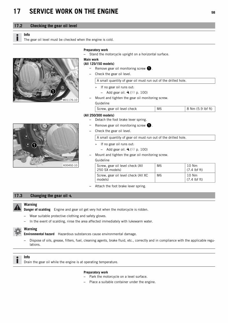
17 SERVICE WORK ON THE ENGINE 98
17.2 Checking the gear oil level
InfoThe gear oil level must be checked when the engine is cold.
Preparatory work– Stand the motorcycle upright on a horizontal surface.
M01176-10
Main work(All 125/150 models)
– Remove gear oil monitoring screw.
– Check the gear oil level.
A small quantity of gear oil must run out of the drilled hole.
» If no gear oil runs out:
– Add gear oil. ( p. 100)
– Mount and tighten the gear oil monitoring screw.
Guideline
Screw, gear oil level check M6 8 Nm (5.9 lbf ft)
(All 250/300 models)– Detach the foot brake lever spring.
K00492-10
– Remove gear oil monitoring screw.
– Check the gear oil level.
A small quantity of gear oil must run out of the drilled hole.
» If no gear oil runs out:
– Add gear oil. ( p. 100)
– Mount and tighten the gear oil monitoring screw.
Guideline
Screw, gear oil level check (All250 SX models)
M6 10 Nm(7.4 lbf ft)
Screw, gear oil level check (All XCmodels)
M6 10 Nm(7.4 lbf ft)
– Attach the foot brake lever spring.
17.3 Changing the gear oil
WarningDanger of scalding Engine and gear oil get very hot when the motorcycle is ridden.
– Wear suitable protective clothing and safety gloves.
– In the event of scalding, rinse the area affected immediately with lukewarm water.
WarningEnvironmental hazard Hazardous substances cause environmental damage.
– Dispose of oils, grease, filters, fuel, cleaning agents, brake fluid, etc., correctly and in compliance with the applicable regu-lations.
InfoDrain the gear oil while the engine is at operating temperature.
Preparatory work– Park the motorcycle on a level surface.
– Place a suitable container under the engine.
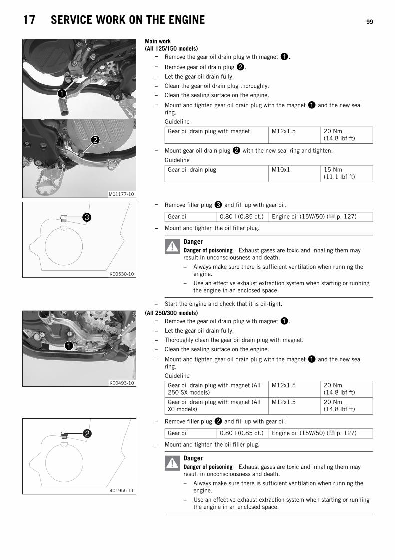
17 SERVICE WORK ON THE ENGINE 99
M01177-10
Main work(All 125/150 models)
– Remove the gear oil drain plug with magnet.
– Remove gear oil drain plug.
– Let the gear oil drain fully.
– Clean the gear oil drain plug thoroughly.
– Clean the sealing surface on the engine.
– Mount and tighten gear oil drain plug with the magnet and the new sealring.
Guideline
Gear oil drain plug with magnet M12x1.5 20 Nm(14.8 lbf ft)
– Mount gear oil drain plug with the new seal ring and tighten.
Guideline
Gear oil drain plug M10x1 15 Nm(11.1 lbf ft)
K00530-10
– Remove filler plug and fill up with gear oil.
Gear oil 0.80 l (0.85 qt.) Engine oil (15W/50) ( p. 127)
– Mount and tighten the oil filler plug.
DangerDanger of poisoning Exhaust gases are toxic and inhaling them mayresult in unconsciousness and death.
– Always make sure there is sufficient ventilation when running theengine.
– Use an effective exhaust extraction system when starting or runningthe engine in an enclosed space.
– Start the engine and check that it is oil-tight.
K00493-10
(All 250/300 models)– Remove the gear oil drain plug with magnet.
– Let the gear oil drain fully.
– Thoroughly clean the gear oil drain plug with magnet.
– Clean the sealing surface on the engine.
– Mount and tighten gear oil drain plug with the magnet and the new sealring.
Guideline
Gear oil drain plug with magnet (All250 SX models)
M12x1.5 20 Nm(14.8 lbf ft)
Gear oil drain plug with magnet (AllXC models)
M12x1.5 20 Nm(14.8 lbf ft)
401955-11
– Remove filler plug and fill up with gear oil.
Gear oil 0.80 l (0.85 qt.) Engine oil (15W/50) ( p. 127)
– Mount and tighten the oil filler plug.
DangerDanger of poisoning Exhaust gases are toxic and inhaling them mayresult in unconsciousness and death.
– Always make sure there is sufficient ventilation when running theengine.
– Use an effective exhaust extraction system when starting or runningthe engine in an enclosed space.

17 SERVICE WORK ON THE ENGINE 100
– Start the engine and check that it is oil-tight.
Finishing work– Check the gear oil level. ( p. 98)
17.4 Adding gear oil
InfoToo little gear oil or poor-quality gear oil results in premature wear to the transmission.Gear oil must only be topped up when the engine is cold.
Preparatory work– Park the motorcycle on a level surface.
M01176-10
Main work(All 125/150 models)
– Remove gear oil monitoring screw.
K00492-10
(All 250/300 models)– Remove gear oil monitoring screw.
401955-11
– Remove filler plug.
– Add gear oil until it emerges from the drill hole of the gear oil monitoring screw.
Engine oil (15W/50) ( p. 127)
– Mount and tighten the gear oil monitoring screw.
Guideline(All 125/150 models)
Screw, gear oil level check M6 8 Nm (5.9 lbf ft)
(All 250/300 models)
Screw, gear oil level check (All250 SX models)
M6 10 Nm(7.4 lbf ft)
Screw, gear oil level check (All XCmodels)
M6 10 Nm(7.4 lbf ft)
– Mount and tighten filler plug.
Finishing work
DangerDanger of poisoning Exhaust gases are toxic and inhaling them may resultin unconsciousness and death.
– Always make sure there is sufficient ventilation when running theengine.
– Use an effective exhaust extraction system when starting or running theengine in an enclosed space.
– Start the engine and check that it is oil-tight.

18 CLEANING, CARE 101
18.1 Cleaning the motorcycle
NoteMaterial damage Components become damaged or destroyed if a pressure cleaner is used incorrectly.
The high pressure forces water into the electrical components, connectors, throttle cables, and bearings, etc.Pressure which is too high causes malfunctions and destroys components.
– Do not direct the water jet directly on to electrical components, connectors, throttle cables or bearings.
– Maintain a minimum distance between the nozzle of the pressure cleaner and the component.
Minimum clearance 60 cm (23.6 in)
WarningEnvironmental hazard Hazardous substances cause environmental damage.
– Dispose of oils, grease, filters, fuel, cleaning agents, brake fluid, etc., correctly and in compliance with the applicable regu-lations.
InfoIf you clean the motorcycle regularly, its value and appearance will be maintained over a long period.Avoid direct sunlight on the motorcycle during cleaning.
401061-01
– Close off the exhaust system to prevent water from entering.
– Remove coarse dirt particles by spraying gently with water.
– Spray very dirty areas with a normal motorcycle cleaner and then clean with a softbrush.
Motorcycle cleaner ( p. 129)
InfoUse warm water containing normal motorcycle cleaner and a soft sponge.Never apply motorcycle cleaner to the dry vehicle; always rinse with waterfirst.
– After rinsing the motorcycle with a gentle water spray, allow it to dry thoroughly.
– Empty the carburetor float chamber. ( p. 97)
– Remove the plug from the exhaust system.
WarningDanger of accidents Moisture and dirt impair the brake system.
– Brake carefully several times to dry out and remove dirt from the brakelinings and the brake discs.
– After cleaning, take a short ride until the engine reaches operating temperature.
InfoThe heat produced causes water at inaccessible locations in the engine andbrake system to evaporate.
– After the motorcycle has cooled off, lubricate all moving parts and bearings.
– Clean the chain. ( p. 60)
– Treat bare metal parts (except for brake discs and exhaust system) withanti-corrosion materials.
Preserving materials for paints, metal and rubber ( p. 129)
– Treat all plastic parts and powder-coated parts with a mild cleaning and care prod-uct.
Special cleaner for glossy and matte paint finishes, metal and plastic surfaces( p. 129)

19 STORAGE 102
19.1 Storage
WarningDanger of poisoning Fuel is poisonous and a health hazard.
– Avoid skin, eye and clothing contact with fuel.
– Immediately consult a doctor if you swallow fuel.
– Do not inhale fuel vapors.
– In case of skin contact, rinse the affected area with plenty of water.
– Rinse the eyes thoroughly with water, and consult a doctor in case of fuel contact with the eyes.
– Change your clothing in case of fuel spills on them.
– Keep fuels correctly in a suitable canister, and out of the reach of children.
InfoIf you plan to garage the motorcycle for a longer period, perform the following steps or have them performed.Before storing the motorcycle, check all parts for function and wear. If service, repairs, or replacements are necessary, youshould do this during the storage period (less workshop overload). In this way, you can avoid long workshop waiting times atthe start of the new season.
401058-01
– When refueling for the last time before taking the motorcycle out of service, addfuel additive.
Fuel additive ( p. 129)
– Refuel. ( p. 27)
– Clean the motorcycle. ( p. 101)
– Change the gear oil. ( p. 98)
– Check the antifreeze and coolant level. ( p. 85)
– Empty the carburetor float chamber. ( p. 97)
– Check the tire air pressure. ( p. 79)
(All XC models)– Remove the battery. ( p. 81)
(All XC models)– Recharge the battery. ( p. 82)
Guideline
Storage temperature of battery with-out direct sunshine
0… 35 °C (32… 95 °F)
– Store the vehicle in a dry location that is not subject to large fluctuations in tem-perature.
InfoKTM recommends jacking up the motorcycle.
– Raise the motorcycle with a lift stand. ( p. 42)
– Cover the vehicle with a tarp or similar cover that is permeable to air.
InfoDo not use non-porous materials since they prevent humidity from escaping,thus causing corrosion.Avoid running the engine for a short time only. Because the engine will notwarm up sufficiently, the water vapor produced during combustion will con-dense, causing engine parts and the exhaust system to rust.

19 STORAGE 103
19.2 Preparing for use after storage
401059-01
(All XC models)– Install the battery. ( p. 81)
– Remove the motorcycle from the lift stand. ( p. 42)
– Perform checks and maintenance work when preparing the vehicle for use.( p. 24)
– Make a test ride.

20 TROUBLESHOOTING 104
Faults Possible cause Action
The engine cannot be cranked (elec-tric starter)(All XC models)
Operating error – Carry out the start procedure. ( p. 24)
Battery discharged – Recharge the battery. ( p. 82)
– Check the charging voltage.
– Check the closed current.
– Check the alternator.
Main fuse blown – Change the main fuse. ( p. 83)
Starter relay faulty – Check the starter relay.
Starter motor faulty – Check the starter motor.
Engine turns but does not start Operating error – Carry out the start procedure. ( p. 24)
Motorcycle was out of use for a longtime and there is old fuel in the floatchamber
– Empty the carburetor float chamber.( p. 97)
Fuel feed interrupted – Check the fuel tank breather.
– Clean the fuel tap.
– Check/set the carburetor components.
Spark plug oily or wet – Clean and dry the spark plug, or change it ifnecessary.
Electrode distance (plug gap) of sparkplug too wide
– Adjust the plug gap.
Guideline(All 125/150 models)
Spark plug electrode gap0.60 mm (0.0236 in)
(All 250/300 models)Spark plug electrode gap (All 250 SX mod-els)0.60 mm (0.0236 in)Spark plug electrode gap (All XC models)0.60 mm (0.0236 in)
Fault in ignition system – Check the ignition system.
Kill switch cable in wiring harnessfrayed, kill switch defective
– Check the kill switch.
The connector or ignition coil is looseor oxidized
– Clean the connector and treat it with contactspray.
Water in carburetor or jets blocked – Check/set the carburetor components.
Engine has no idle Idling jet blocked – Check/set the carburetor components.
Adjusting screws on carburetor dis-torted
– Carburetor – adjust the idle speed.( p. 93)
Spark plug defective – Change the spark plug.
Ignition system defective – Check the ignition coil.
– Check the spark plug connector.
Engine does not speed up Carburetor running over because floatneedle dirty or worn
– Check/set the carburetor components.
Loose carburetor jets – Check/set the carburetor components.
Fault in ignition system – Check the ignition system.
Engine has too little power Fuel feed interrupted – Check the fuel tank breather.
– Clean the fuel tap.
– Check/set the carburetor components.
Air filter very dirty – Clean the air filter and air filter box.( p. 54)
Exhaust system leaky, deformed ortoo little glass fiber yarn filling inmain silencer
– Check exhaust system for damage.
– Change glass fiber yarn filling in the mainsilencer. ( p. 56)
Fault in ignition system – Check the ignition system.
Diaphragm or reed valve housingdamaged
– Check the diaphragm and reed valve housing.

20 TROUBLESHOOTING 105
Faults Possible cause Action
Engine stalls or is popping into thecarburetor
Lack of fuel (All SX models)– Turn handle of the fuel tap to the ON
position. (Figure K00510-10 p. 15)
(All XC models)– Turn handle of the fuel tap to the ON
position. (Figure K00488-10 p. 15)
(All XC models)– Turn handle of the fuel tap to the RES
position. (Figure K00488-10 p. 15)
– Refuel. ( p. 27)
Engine takes in bad air – Check the intake flange and carburetor fortightness.
The connector or ignition coil is looseor oxidized
– Clean the connector and treat it with contactspray.
Engine overheats Too little coolant in cooling system – Check the cooling system for leakage.
– Check the coolant level. ( p. 86)
Too little air stream – Switch off engine when stationary.
Radiator fins very dirty – Clean the radiator fins.
Foam formation in cooling system – Drain the coolant. ( p. 87)
– Refill with coolant. ( p. 87)
Damaged cylinder head or cylinderhead gasket
– Check the cylinder head and cylinder head gas-ket.
Bent radiator hose – Change the radiator hose.
Incorrect ignition point due to loosestator
– Adjust the ignition.
White smoke emission (steam inexhaust gas)
Damaged cylinder head or cylinderhead gasket
– Check the cylinder head and cylinder head gas-ket.
Gear oil exits at the vent hose Too much gear oil added – Check the gear oil level. ( p. 98)
Water in the gear oil Damaged shaft seal ring or waterpump
– Check the shaft seal ring and water pump.

21 TECHNICAL DATA 106
21.1 Engine
21.1.1 All 125 models
Design 1-cylinder 2-stroke engine, water-cooled, with reed intake andexhaust control
Displacement 124.8 cm³ (7.616 cu in)
Stroke 54.5 mm (2.146 in)
Bore 54 mm (2.13 in)
Crankshaft bearing 1 grooved ball bearing/1 roller bearing
Conrod bearing Needle bearing
Piston pin bearing Needle bearing
Pistons Cast aluminum
Piston rings 2 half keystone rings
X (upper edge of piston to upper edge of cylinder) 0… 0.10 mm (0… 0.0039 in)
Z (height of control flap) 36.5 mm (1.437 in)
Primary transmission 23:73
Clutch Multidisc clutch in oil bath/hydraulically activated
Gearbox 6-gear, claw shifted
Transmission ratio
First gear 14:32
Second gear 15:30
Third gear 17:28
Fourth gear 20:28
Fifth gear 19:23
Sixth gear 22:24
Ignition Contactless controlled fully electronic ignition with digital igni-tion adjustment, type Kokusan
Spark plug NGK BR9 ECMVX
Spark plug electrode gap 0.60 mm (0.0236 in)
Starting aid Kick starter
21.1.2 All 150 models
Design 1-cylinder 2-stroke engine, water-cooled, with reed intake andexhaust control
Displacement 144 cm³ (8.79 cu in)
Stroke 54.5 mm (2.146 in)
Bore 58 mm (2.28 in)
Crankshaft bearing 1 grooved ball bearing/1 roller bearing
Conrod bearing Needle bearing
Piston pin bearing Needle bearing
Pistons Forged aluminum
Piston rings 1 rectangular ring, 1 half keystone ring
X (upper edge of piston to upper edge of cylinder) 0… 0.10 mm (0… 0.0039 in)
Z (height of control flap) 36.5 mm (1.437 in)
Primary transmission 23:73
Clutch Multidisc clutch in oil bath/hydraulically activated
Gearbox 6-gear, claw shifted
Transmission ratio
First gear 14:32
Second gear 15:30
Third gear 17:28
Fourth gear 20:28
Fifth gear 19:23

21 TECHNICAL DATA 107
Sixth gear 22:24
Ignition Contactless controlled fully electronic ignition with digital igni-tion adjustment, type Kokusan
Spark plug NGK BR9 ECMVX
Spark plug electrode gap 0.60 mm (0.0236 in)
Starting aid Kick starter
21.1.3 All 250 SX models
Design 1-cylinder 2-stroke engine, water-cooled, with reed intake andexhaust control
Displacement 249 cm³ (15.19 cu in)
Stroke 72 mm (2.83 in)
Hole 66.4 mm (2.614 in)
Exhaust valve, beginning of adjustment 5,125 rpm
Crankshaft bearing 1 grooved ball bearing/1 roller bearing
Conrod bearing Needle bearing
Piston pin bearing Needle bearing
Piston Cast aluminum
Piston rings 2 half keystone rings
X distance (upper edge of piston to upper edge of cylinder) 0… 0.10 mm (0… 0.0039 in)
Z distance (height of control flap) 49 mm (1.93 in)
Primary transmission 26:73
Clutch Multidisc clutch in oil bath/hydraulically activated
Transmission 5-gear, claw shifted
Transmission ratio
First gear 14:28
Second gear 16:26
Third gear 18:24
Fourth gear 21:24
Fifth gear 22:21
Ignition system Contactless controlled, fully electronic ignition with digital igni-tion adjustment, type Kokusan
Spark plug NGK BR 8 ECM
Spark plug electrode gap 0.60 mm (0.0236 in)
Starting aid Kick starter
21.1.4 250 XC US
Design 1-cylinder 2-stroke engine, water-cooled, with reed intake andexhaust control
Displacement 249 cm³ (15.19 cu in)
Stroke 72 mm (2.83 in)
Hole 66.4 mm (2.614 in)
Exhaust valve, beginning of adjustment 5,125 rpm
Crankshaft bearing 1 grooved ball bearing/1 roller bearing
Conrod bearing Needle bearing
Piston pin bearing Needle bearing
Piston Cast aluminum
Piston rings 2 half keystone rings
X distance (upper edge of piston to upper edge of cylinder) 0… 0.10 mm (0… 0.0039 in)
Z distance (height of control flap) 49 mm (1.93 in)
Primary transmission 26:73
Clutch Multidisc clutch in oil bath/hydraulically activated
Transmission 6-gear, claw shifted

21 TECHNICAL DATA 108
Transmission ratio
First gear 15:31
Second gear 16:25
Third gear 20:25
Fourth gear 22:23
Fifth gear 25:22
Sixth gear 26:20
Ignition system Contactless controlled, fully electronic ignition with digital igni-tion adjustment, type Kokusan
Spark plug NGK BR 7 ES
Spark plug electrode gap 0.60 mm (0.0236 in)
Starting aid Kick starter and electric starter
21.1.5 300 XC US
Design 1-cylinder 2-stroke engine, water-cooled, with reed intake andexhaust control
Displacement 293.2 cm³ (17.892 cu in)
Stroke 72 mm (2.83 in)
Hole 72 mm (2.83 in)
Exhaust valve, beginning of adjustment 5,150 rpm
Crankshaft bearing 1 grooved ball bearing/1 roller bearing
Conrod bearing Needle bearing
Piston pin bearing Needle bearing
Piston Cast aluminum
Piston rings 2 rectangular rings
X distance (upper edge of piston to upper edge of cylinder) 0… 0.10 mm (0… 0.0039 in)
Z distance (height of control flap) 49.5 mm (1.949 in)
Primary transmission 26:73
Clutch Multidisc clutch in oil bath/hydraulically activated
Transmission 6-gear, claw shifted
Transmission ratio
First gear 15:31
Second gear 16:25
Third gear 20:25
Fourth gear 22:23
Fifth gear 25:22
Sixth gear 26:20
Ignition system Contactless controlled, fully electronic ignition with digital igni-tion adjustment, type Kokusan
Spark plug NGK BR 7 ES
Spark plug electrode gap 0.60 mm (0.0236 in)
Starting aid Kick starter and electric starter
21.2 Engine tightening torques
21.2.1 All 125/150 models
Screw, inner membrane sheets EJOT DELTA PT® 35x25 1 Nm (0.7 lbf ft) –
Screw, membrane core plate EJOT DELTA PT® 30x12 1 Nm (0.7 lbf ft) –
Screw, outer membrane sheets EJOT DELTA PT® 30x6 1 Nm (0.7 lbf ft) –
Screw, control lever, exhaust control M5 6 Nm (4.4 lbf ft) Loctite® 243™
Screw, crankshaft position sensor M5 6 Nm (4.4 lbf ft) Loctite® 243™
Screw, exhaust control cover M5 6 Nm (4.4 lbf ft) –
Screw, locking lever M5 6 Nm (4.4 lbf ft) Loctite® 243™

21 TECHNICAL DATA 109
Screw, retaining bracket, rotary valve M5 6 Nm (4.4 lbf ft) –
Screw, stator M5 6 Nm (4.4 lbf ft) Loctite® 243™
Screw, water pump wheel M5 6 Nm (4.4 lbf ft) Loctite® 243™
Bleeder screw, cylinder head M6 8 Nm (5.9 lbf ft) –
Drain plug, water pump cover M6 8 Nm (5.9 lbf ft) –
Nut, adjusting screw, power valve M6 8 Nm (5.9 lbf ft) –
Screw, alternator cover M6 8 Nm (5.9 lbf ft) –
Screw, bearing retainer M6 10 Nm (7.4 lbf ft) Loctite® 243™
Screw, clutch slave cylinder M6 10 Nm (7.4 lbf ft) –
Screw, clutch spring retainer M6 10 Nm (7.4 lbf ft) –
Screw, control lever, exhaust control M6 10 Nm (7.4 lbf ft) Loctite® 243™
Screw, engine case M6 10 Nm (7.4 lbf ft) –
Screw, exhaust flange M6 10 Nm (7.4 lbf ft) –
Screw, gear oil level check M6 8 Nm (5.9 lbf ft) –
Screw, intake flange/reed valve housing M6 6 Nm (4.4 lbf ft) –
Screw, intermediate clutch cover M6x20 10 Nm (7.4 lbf ft) –
Screw, intermediate clutch cover M6x25 10 Nm (7.4 lbf ft) –
Screw, intermediate clutch cover M6x30 10 Nm (7.4 lbf ft) –
Screw, kick starter stop plate M6 10 Nm (7.4 lbf ft) Loctite® 243™
Screw, outer clutch cover M6x20 8 Nm (5.9 lbf ft) –
Screw, outer clutch cover M6x50 8 Nm (5.9 lbf ft) –
Screw, shift drum locating M6 10 Nm (7.4 lbf ft) Loctite® 243™
Screw, shift lever M6 14 Nm (10.3 lbf ft) Loctite® 243™
Screw, stop plate of exhaust control M6 10 Nm (7.4 lbf ft) Loctite® 243™
Screw, water pump cover M6 10 Nm (7.4 lbf ft) –
Screw, cylinder head M7 18 Nm (13.3 lbf ft) –
Nut, cylinder base M8 23 Nm (17 lbf ft) –
Screw, cylinder base M8 20 Nm (14.8 lbf ft) –
Screw, kick starter M8 25 Nm (18.4 lbf ft) Loctite® 243™
Gear oil drain plug M10x1 15 Nm (11.1 lbf ft) –
Nut, rotor M12x1 60 Nm (44.3 lbf ft) –
Gear oil drain plug with magnet M12x1.5 20 Nm (14.8 lbf ft) –
Spark plug M14x1.25 25 Nm (18.4 lbf ft) –
Nut, primary gear M16LHx1.5 130 Nm (95.9 lbf ft) Loctite® 243™
Nut, inner clutch hub M18x1.5 100 Nm (73.8 lbf ft) Loctite® 243™
21.2.2 All 250 SX models
Screw, inner membrane sheets EJOT DELTA PT® 35x25 1 Nm (0.7 lbf ft) –
Screw, membrane support plate EJOT DELTA PT® 30x12 1 Nm (0.7 lbf ft) –
Screw, outer membrane sheets EJOT DELTA PT® 30x6 1 Nm (0.7 lbf ft) –
Screw, angle lever, exhaust control M5 6 Nm (4.4 lbf ft) Loctite® 243™
Screw, bearing retainer M5 7 Nm (5.2 lbf ft) Loctite® 243™
Screw, clutch spring retainer M5 6 Nm (4.4 lbf ft) –
Screw, crankshaft position sensor M5 6 Nm (4.4 lbf ft) Loctite® 243™
Screw, exhaust control bearing support M5 6 Nm (4.4 lbf ft) Loctite® 243™
Screw, exhaust control cap M5 5 Nm (3.7 lbf ft) –
Screw, exhaust control cover M5 6 Nm (4.4 lbf ft) –
Screw, locking lever M5 6 Nm (4.4 lbf ft) Loctite® 243™
Screw, retaining bracket of exhaustcontrol
M5 7 Nm (5.2 lbf ft) Loctite® 2701™
Screw, stator M5 6 Nm (4.4 lbf ft) Loctite® 243™
Screw, water pump impeller M5 6 Nm (4.4 lbf ft) Loctite® 243™

21 TECHNICAL DATA 110
Bleeder screw, cylinder head M6 10 Nm (7.4 lbf ft) –
Outer clutch cover M6 8 Nm (5.9 lbf ft) –
Screw, alternator cover M6 8 Nm (5.9 lbf ft) –
Screw, clutch slave cylinder M6 10 Nm (7.4 lbf ft) –
Screw, control flap, exhaust control M6 10 Nm (7.4 lbf ft) Loctite® 243™
Screw, engine case M6 10 Nm (7.4 lbf ft) –
Screw, exhaust flange M6 8 Nm (5.9 lbf ft) –
Screw, gear oil level check M6 10 Nm (7.4 lbf ft) –
Screw, idler gear retaining bracket M6 10 Nm (7.4 lbf ft) –
Screw, intake flange/reed valve housing M6 6 Nm (4.4 lbf ft) –
Screw, intermediate clutch cover M6 10 Nm (7.4 lbf ft) –
Screw, kick starter stop plate M6 10 Nm (7.4 lbf ft) Loctite® 243™
Screw, shift drum locating M6 10 Nm (7.4 lbf ft) Loctite® 243™
Screw, shift lever M6 14 Nm (10.3 lbf ft) Loctite® 243™
Screw, water pump cover M6 10 Nm (7.4 lbf ft) –
Screw, balancer shaft M8 30 Nm (22.1 lbf ft) Loctite® 243™
Screw, cylinder head M8 27 Nm (19.9 lbf ft) –
Screw, kick starter M8 25 Nm (18.4 lbf ft) Loctite® 2701™
Nut, cylinder base M10 35 Nm (25.8 lbf ft) –
Screw, drive chain engine sprocket M10 60 Nm (44.3 lbf ft) Loctite® 2701™
Nut, rotor M12x1 60 Nm (44.3 lbf ft) –
Gear oil drain plug with magnet M12x1.5 20 Nm (14.8 lbf ft) –
Spark plug M14x1.25 25 Nm (18.4 lbf ft) –
Nut, inner clutch hub M18x1.5 100 Nm (73.8 lbf ft) Loctite® 648™
Nut, primary gear M18LHx1.5 150 Nm (110.6 lbf ft) Loctite® 648™
21.2.3 All XC models
Screw, inner membrane sheets EJOT DELTA PT® 35x25 1 Nm (0.7 lbf ft) –
Screw, membrane support plate EJOT DELTA PT® 30x12 1 Nm (0.7 lbf ft) –
Screw, outer membrane sheets EJOT DELTA PT® 30x6 1 Nm (0.7 lbf ft) –
Screw, angle lever, exhaust control M5 6 Nm (4.4 lbf ft) Loctite® 243™
Screw, bearing retainer M5 7 Nm (5.2 lbf ft) Loctite® 243™
Screw, clutch spring retainer M5 6 Nm (4.4 lbf ft) –
Screw, exhaust control bearing support M5 6 Nm (4.4 lbf ft) Loctite® 243™
Screw, exhaust control cap M5 5 Nm (3.7 lbf ft) –
Screw, exhaust control cover M5 6 Nm (4.4 lbf ft) –
Screw, locking lever M5 6 Nm (4.4 lbf ft) Loctite® 243™
Screw, retaining bracket of exhaustcontrol
M5 7 Nm (5.2 lbf ft) Loctite® 2701™
Screw, starter motor protection cap M5 6 Nm (4.4 lbf ft) –
Screw, water pump impeller M5 6 Nm (4.4 lbf ft) Loctite® 243™
Bleeder screw, cylinder head M6 10 Nm (7.4 lbf ft) –
Outer clutch cover M6 8 Nm (5.9 lbf ft) –
Screw, alternator cover M6 10 Nm (7.4 lbf ft) –
Screw, clutch slave cylinder M6 10 Nm (7.4 lbf ft) –
Screw, control flap, exhaust control M6 10 Nm (7.4 lbf ft) Loctite® 243™
Screw, engine case M6 10 Nm (7.4 lbf ft) –
Screw, exhaust flange M6 8 Nm (5.9 lbf ft) –
Screw, gear oil level check M6 10 Nm (7.4 lbf ft) –
Screw, intake flange/reed valve housing M6 6 Nm (4.4 lbf ft) –
Screw, intermediate clutch cover M6 10 Nm (7.4 lbf ft) –
Screw, kick starter stop plate M6 10 Nm (7.4 lbf ft) Loctite® 243™

21 TECHNICAL DATA 111
Screw, shift drum locating M6 10 Nm (7.4 lbf ft) Loctite® 243™
Screw, shift lever M6 14 Nm (10.3 lbf ft) Loctite® 243™
Screw, starter motor M6 10 Nm (7.4 lbf ft) Loctite® 243™
Screw, stator M6 10 Nm (7.4 lbf ft) Loctite® 243™
Screw, water pump cover M6 10 Nm (7.4 lbf ft) –
Screw, balancer shaft M8 30 Nm (22.1 lbf ft) Loctite® 243™
Screw, cylinder head M8 27 Nm (19.9 lbf ft) –
Screw, kick starter M8 25 Nm (18.4 lbf ft) Loctite® 2701™
Nut, cylinder base M10 35 Nm (25.8 lbf ft) –
Screw, drive chain engine sprocket M10 60 Nm (44.3 lbf ft) Loctite® 2701™
Nut, rotor M12x1 60 Nm (44.3 lbf ft) –
Gear oil drain plug with magnet M12x1.5 20 Nm (14.8 lbf ft) –
Spark plug M14x1.25 25 Nm (18.4 lbf ft) –
Nut, inner clutch hub M18x1.5 100 Nm (73.8 lbf ft) Loctite® 648™
Nut, primary gear M18LHx1.5 150 Nm (110.6 lbf ft) Loctite® 648™

21 TECHNICAL DATA 112
21.3 Carburetor
21.3.1 All 125 models
Carburetor type MIKUNI TMX 38
Carburetor identification number TMX 38 82
Needle position 3rd position from top
Jet needle 6BFY43-74 (6BFY44-74, 6BFY44-73, 6BFY43-73)
Main jet 480 (490, 500, 520, 540)
Idling jet 45 (42.5/47.5)
Starting jet 80
Needle jet S‑1
Idle air adjusting screw
Open 1.5 turns
21.3.2 Carburetor - basic setting for sandy surfaces (All 125 models)
Idle air adjusting screw
Open 1.5 turns
Idling jet 45
Jet needle 6BFY44‑73
Needle position 3rd position from top
Main jet 560
InfoIf the engine is not running smoothly, use a smaller main jet.

21 TECHNICAL DATA 113
21.3.3 Carburetor tuning (All 125 models)
402669-01
M/FT ASL Sea level
TEMP Temperature
ASO Idle air adjusting screw open
IJ Idling jet
NDL Needle
POS Needle position from top
MJ Main jet
InfoDo not use on sandy terrain.

21 TECHNICAL DATA 114
21.3.4 All 150 models
Carburetor type MIKUNI TMX 38
Carburetor identification number TMX 38 83
Needle position 3rd position from top
Jet needle 6BFY43-74 (6BFY44-74, 6BFY44-73, 6BFY43-73)
Main jet 470 (460, 480, 490, 500, 520)
Idling jet 45 (42.5/47.5)
Starting jet 80
Needle jet S‑1
Idle air adjusting screw
Open 1.5 turns
21.3.5 Basic carburetor setting for sandy surfaces (All 150 models)
Idle air adjusting screw
Open 1.5 turns
Idling jet 45
Jet needle 6BFY44‑73
Needle position 3rd position from top
Main jet 540
InfoIf the engine is not running smoothly, use a smaller main jet.

21 TECHNICAL DATA 115
21.3.6 Carburetor tuning (All 150 models)
402670-01
M/FT ASL Sea level
TEMP Temperature
ASO Idle air adjusting screw open
IJ Idling jet
NDL Needle
POS Needle position from top
MJ Main jet
InfoDo not use on sandy terrain.
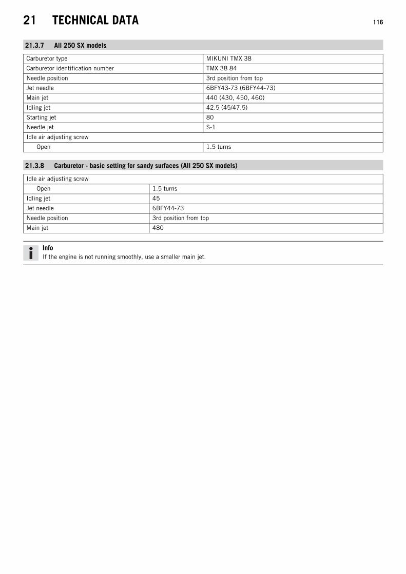
21 TECHNICAL DATA 116
21.3.7 All 250 SX models
Carburetor type MIKUNI TMX 38
Carburetor identification number TMX 38 84
Needle position 3rd position from top
Jet needle 6BFY43-73 (6BFY44-73)
Main jet 440 (430, 450, 460)
Idling jet 42.5 (45/47.5)
Starting jet 80
Needle jet S‑1
Idle air adjusting screw
Open 1.5 turns
21.3.8 Carburetor - basic setting for sandy surfaces (All 250 SX models)
Idle air adjusting screw
Open 1.5 turns
Idling jet 45
Jet needle 6BFY44‑73
Needle position 3rd position from top
Main jet 480
InfoIf the engine is not running smoothly, use a smaller main jet.

21 TECHNICAL DATA 117
21.3.9 Carburetor tuning (All 250 SX models)
402671-01
M/FT ASL Sea level
TEMP Temperature
ASO Idle air adjusting screw open
IJ Idling jet
NDL Needle
POS Needle position from top
MJ Main jet
InfoDo not use on sandy terrain.

21 TECHNICAL DATA 118
21.3.10 250 XC US
Carburetor type MIKUNI TMX 38
Carburetor identification number TMX 38 85
Needle position 3rd position from top
Jet needle 6BFY44-74 (6BFY43-74)
Main jet 440 (430, 450, 460)
Idling jet 37.5 (35/40)
Starting jet 80
Needle jet R‑8
Idle air adjusting screw
Open 1.5 turns
21.3.11 Carburetor tuning (250 XC US)
402672-01
M/FT ASL Sea level
TEMP Temperature
ASO Idle air adjusting screw open
IJ Idling jet

21 TECHNICAL DATA 119
NDL Needle
POS Needle position from top
MJ Main jet
InfoDo not use on sandy terrain.
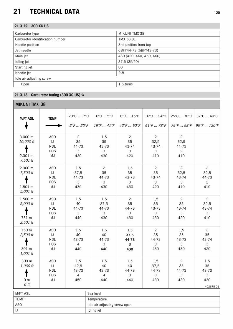
21 TECHNICAL DATA 120
21.3.12 300 XC US
Carburetor type MIKUNI TMX 38
Carburetor identification number TMX 38 81
Needle position 3rd position from top
Jet needle 6BFY44-73 (6BFY43-73)
Main jet 430 (420, 440, 450, 460)
Idling jet 37.5 (35/40)
Starting jet 80
Needle jet R‑8
Idle air adjusting screw
Open 1.5 turns
21.3.13 Carburetor tuning (300 XC US)
402675-01
M/FT ASL Sea level
TEMP Temperature
ASO Idle air adjusting screw open
IJ Idling jet

21 TECHNICAL DATA 121
NDL Needle
POS Needle position from top
MJ Main jet
InfoDo not use on sandy terrain.
21.4 Capacities
21.4.1 Gear oil
Gear oil 0.80 l (0.85 qt.) Engine oil (15W/50) ( p. 127)
21.4.2 Coolant
Coolant 1.2 l (1.3 qt.) Coolant ( p. 127)
21.4.3 Fuel
Total fuel tank capacity,approx. (All SX models)
7 l (1.8 US gal) Super unleaded (98 octane) mixed with 2-stroke engine oil(1:40) ( p. 128) (All 125/150 models)
Super unleaded (95 octane) mixed with 2-stroke engine oil(1:60) ( p. 128) (All 250 SX models)
Total fuel tank capacity,approx. (All XC models)
10 l (2.6 US gal) Super unleaded (95 octane) mixed with 2-stroke engine oil(1:60) ( p. 128)
Fuel reserve approx. (All XC models) 1.5 l (1.6 qt.)
21.5 Chassis
Frame Central tube frame made of chrome molybdenum steel tubing
Fork WP Performance Systems Upside down AER 48
Suspension travel
Front 310 mm (12.2 in)
Rear 300 mm (11.81 in)
Fork offset 22 mm (0.87 in)
Shock absorber (All 125/150 models) WP Performance Systems 5018 DCC Link
Shock absorber (250 SX EU) WP Performance Systems 5018 DCC Link
Shock absorber (250 SX US) WP Performance Systems 5018 DCC Link
Shock absorber (All XC models) WP Performance Systems 5018 DCC Link
Brake system Disc brakes, brake calipers on floating bearings
Brake discs - diameter
Front 260 mm (10.24 in)
Rear 220 mm (8.66 in)
Brake discs - wear limit
Front 2.5 mm (0.098 in)
Rear 3.5 mm (0.138 in)
Tire air pressure off road
Front 1.0 bar (15 psi)
Rear 1.0 bar (15 psi)
Secondary ratio (All 125 models) 13:50
Secondary ratio (All 150 models) 13:48
Secondary ratio (All 250 SX models) 14:50
Secondary ratio (All XC models) 13:50
Chain 5/8 x 1/4"
Rear sprockets available 48, 50, 52
Steering head angle 63.9°

21 TECHNICAL DATA 122
Wheelbase 1,485±10 mm (58.46±0.39 in)
Seat height unloaded 960 mm (37.8 in)
Ground clearance unloaded (All SX models) 375 mm (14.76 in)
Ground clearance unloaded (All XC models) 370 mm (14.57 in)
Weight without fuel, approx. (125/150 SX EU) 87.2 kg (192.2 lb.)
Weight without fuel, approx. (125/150 SX US) 87.2 kg (192.2 lb.)
Weight without fuel, approx. (All 250 SX models) 95.4 kg (210.3 lb.)
Weight without fuel, approx. (All XC models) 98.4 kg (216.9 lb.)
Maximum permissible front axle load 145 kg (320 lb.)
Maximum permissible rear axle load 190 kg (419 lb.)
Maximum permissible overall weight 335 kg (739 lb.)
21.6 Electrical system
Battery (All XC models) HJTZ5S-FP Lithium-ion batteryBattery voltage: 12 VNominal capacity: 2.0 AhMaintenance-free
Fuse (All XC models) 58011109110 10 A
21.7 Tires
Validity Front tires Rear tires
(All 125/150 models) 80/100 - 21 51M TTDunlop GEOMAX MX3S
100/90 - 19 57M TTDunlop GEOMAX MX3S
(All 250 SX models) 80/100 - 21 51M TTDunlop GEOMAX MX3S
110/90 - 19 62M TTDunlop GEOMAX MX3S
(All XC models) 90/90 - 21 54M TTDunlop GEOMAX AT81F
110/100 - 18 64M TTDunlop GEOMAX AT81
Additional information is available in the Service section under:http://www.ktm.com
21.8 Fork
21.8.1 All 125/150 models
Fork article number 34.18.8Q.01
Fork WP Performance Systems Upside down AER 48
Compression damping
Comfort 15 clicks
Standard 12 clicks
Sport 9 clicks
Rebound damping
Comfort 20 clicks
Standard 17 clicks
Sport 14 clicks
Air pressure 8.2 bar (119 psi)
Fork length 950 mm (37.4 in)
Oil capacity external mecha-nism left
200+40−20 ml (6.76+1.35
−0.68 fl. oz.) Fork oil (SAE 4) (48601166S1) ( p. 127)
Oil capacity external mecha-nism right
200+40−20 ml (6.76+1.35
−0.68 fl. oz.) Fork oil (SAE 4) (48601166S1) ( p. 127)
Grease capacity, left cartridge 11 ml (0.37 fl. oz.) Multi-purpose grease (00062010051) ( p. 128)
Oil capacity, right cartridge 380 ml (12.85 fl. oz.) Fork oil (SAE 4) (48601166S1) ( p. 127)
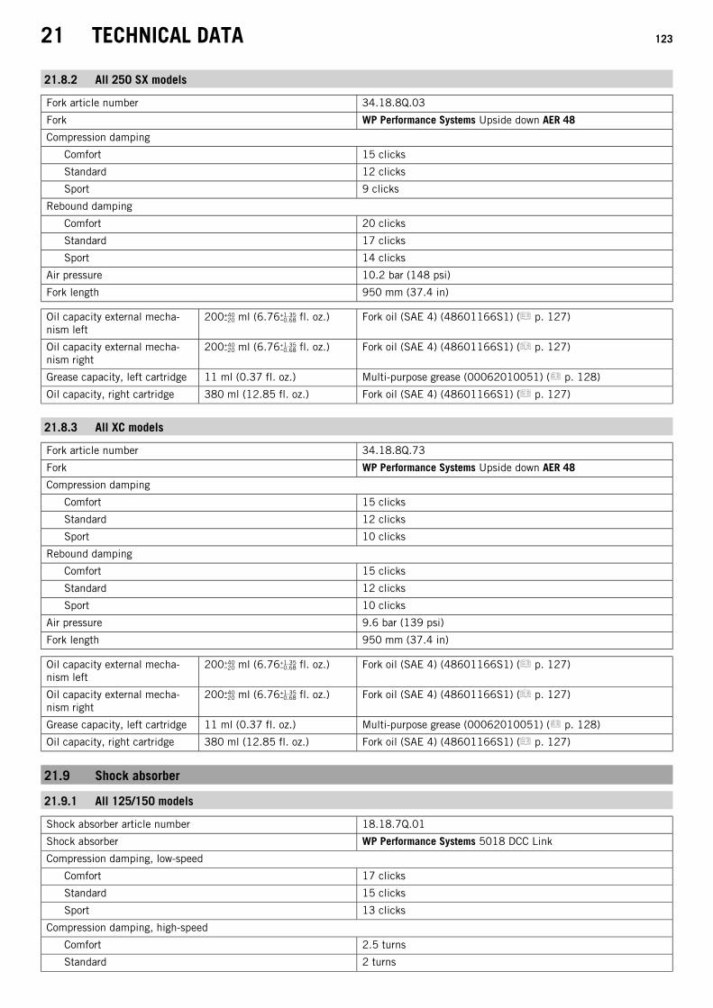
21 TECHNICAL DATA 123
21.8.2 All 250 SX models
Fork article number 34.18.8Q.03
Fork WP Performance Systems Upside down AER 48
Compression damping
Comfort 15 clicks
Standard 12 clicks
Sport 9 clicks
Rebound damping
Comfort 20 clicks
Standard 17 clicks
Sport 14 clicks
Air pressure 10.2 bar (148 psi)
Fork length 950 mm (37.4 in)
Oil capacity external mecha-nism left
200+40−20 ml (6.76+1.35
−0.68 fl. oz.) Fork oil (SAE 4) (48601166S1) ( p. 127)
Oil capacity external mecha-nism right
200+40−20 ml (6.76+1.35
−0.68 fl. oz.) Fork oil (SAE 4) (48601166S1) ( p. 127)
Grease capacity, left cartridge 11 ml (0.37 fl. oz.) Multi-purpose grease (00062010051) ( p. 128)
Oil capacity, right cartridge 380 ml (12.85 fl. oz.) Fork oil (SAE 4) (48601166S1) ( p. 127)
21.8.3 All XC models
Fork article number 34.18.8Q.73
Fork WP Performance Systems Upside down AER 48
Compression damping
Comfort 15 clicks
Standard 12 clicks
Sport 10 clicks
Rebound damping
Comfort 15 clicks
Standard 12 clicks
Sport 10 clicks
Air pressure 9.6 bar (139 psi)
Fork length 950 mm (37.4 in)
Oil capacity external mecha-nism left
200+40−20 ml (6.76+1.35
−0.68 fl. oz.) Fork oil (SAE 4) (48601166S1) ( p. 127)
Oil capacity external mecha-nism right
200+40−20 ml (6.76+1.35
−0.68 fl. oz.) Fork oil (SAE 4) (48601166S1) ( p. 127)
Grease capacity, left cartridge 11 ml (0.37 fl. oz.) Multi-purpose grease (00062010051) ( p. 128)
Oil capacity, right cartridge 380 ml (12.85 fl. oz.) Fork oil (SAE 4) (48601166S1) ( p. 127)
21.9 Shock absorber
21.9.1 All 125/150 models
Shock absorber article number 18.18.7Q.01
Shock absorber WP Performance Systems 5018 DCC Link
Compression damping, low-speed
Comfort 17 clicks
Standard 15 clicks
Sport 13 clicks
Compression damping, high-speed
Comfort 2.5 turns
Standard 2 turns

21 TECHNICAL DATA 124
Sport 1.5 turns
Rebound damping
Comfort 17 clicks
Standard 15 clicks
Sport 13 clicks
Spring preload 6 mm (0.24 in)
Spring rate
Weight of rider: 65… 75 kg (143… 165 lb.) 36 N/mm (206 lb/in)
Weight of rider: 75… 85 kg (165… 187 lb.) 39 N/mm (223 lb/in)
Weight of rider: 85… 95 kg (187… 209 lb.) 42 N/mm (240 lb/in)
Spring length 247 mm (9.72 in)
Gas pressure 10 bar (145 psi)
Static sag 35 mm (1.38 in)
Riding sag 105 mm (4.13 in)
Fitted length 477 mm (18.78 in)
Shock absorber fluid ( p. 128) SAE 2.5
21.9.2 250 SX EU
Shock absorber article number 18.18.7Q.03
Shock absorber WP Performance Systems 5018 DCC Link
Compression damping, low-speed
Comfort 17 clicks
Standard 15 clicks
Sport 13 clicks
Compression damping, high-speed
Comfort 2.5 turns
Standard 2 turns
Sport 1.5 turns
Rebound damping
Comfort 17 clicks
Standard 15 clicks
Sport 13 clicks
Spring preload 8 mm (0.31 in)
Spring rate
Weight of rider: 65… 75 kg (143… 165 lb.) 39 N/mm (223 lb/in)
Weight of rider: 75… 85 kg (165… 187 lb.) 42 N/mm (240 lb/in)
Weight of rider: 85… 95 kg (187… 209 lb.) 45 N/mm (257 lb/in)
Spring length 247 mm (9.72 in)
Gas pressure 10 bar (145 psi)
Static sag 35 mm (1.38 in)
Riding sag 105 mm (4.13 in)
Fitted length 477 mm (18.78 in)
Shock absorber fluid ( p. 128) SAE 2.5
21.9.3 250 SX US
Shock absorber article number 18.18.7Q.53
Shock absorber WP Performance Systems 5018 DCC Link
Compression damping, low-speed
Comfort 17 clicks
Standard 15 clicks
Sport 13 clicks
Compression damping, high-speed

21 TECHNICAL DATA 125
Comfort 2.5 turns
Standard 2 turns
Sport 1.5 turns
Rebound damping
Comfort 17 clicks
Standard 15 clicks
Sport 13 clicks
Spring preload 5 mm (0.2 in)
Spring rate
Weight of rider: 65… 75 kg (143… 165 lb.) 39 N/mm (223 lb/in)
Weight of rider: 75… 85 kg (165… 187 lb.) 42 N/mm (240 lb/in)
Weight of rider: 85… 95 kg (187… 209 lb.) 45 N/mm (257 lb/in)
Spring length 247 mm (9.72 in)
Gas pressure 10 bar (145 psi)
Static sag 35 mm (1.38 in)
Riding sag 105 mm (4.13 in)
Fitted length 477 mm (18.78 in)
Shock absorber fluid ( p. 128) SAE 2.5
21.9.4 All XC models
Shock absorber article number 18.18.7Q.73
Shock absorber WP Performance Systems 5018 DCC Link
Compression damping, low-speed
Comfort 17 clicks
Standard 15 clicks
Sport 13 clicks
Compression damping, high-speed
Comfort 2.5 turns
Standard 2 turns
Sport 1.5 turns
Rebound damping
Comfort 17 clicks
Standard 15 clicks
Sport 13 clicks
Spring preload 7 mm (0.28 in)
Spring rate
Weight of rider: 65… 75 kg (143… 165 lb.) 39 N/mm (223 lb/in)
Weight of rider: 75… 85 kg (165… 187 lb.) 42 N/mm (240 lb/in)
Weight of rider: 85… 95 kg (187… 209 lb.) 45 N/mm (257 lb/in)
Spring length 247 mm (9.72 in)
Gas pressure 10 bar (145 psi)
Static sag 35 mm (1.38 in)
Riding sag 105 mm (4.13 in)
Fitted length 477 mm (18.78 in)
Shock absorber fluid ( p. 128) SAE 2.5

21 TECHNICAL DATA 126
21.10 Chassis tightening torques
Screw, fixed grip M4 5 Nm (3.7 lbf ft) Loctite® 243™
Screw, service hour counter M4 1 Nm (0.7 lbf ft) –
Spoke nipple, front wheel M4.5 6 Nm (4.4 lbf ft) –
Spoke nipple, rear wheel M4.5 6 Nm (4.4 lbf ft) –
Remaining nuts, chassis M5 5 Nm (3.7 lbf ft) –
Remaining screws, chassis M5 5 Nm (3.7 lbf ft) –
Screw, battery terminal (All XC models) M5 2.5 Nm (1.84 lbf ft) –
Screw, shock absorber adjusting ring M5 5 Nm (3.7 lbf ft) –
Screws on the main silencer M5 7 Nm (5.2 lbf ft) –
Nut, cable on starter motor (All XCmodels)
M6 4 Nm (3 lbf ft) –
Remaining nuts, chassis M6 10 Nm (7.4 lbf ft) –
Remaining screws, chassis M6 10 Nm (7.4 lbf ft) –
Screw, absorbing element on frame M6 6 Nm (4.4 lbf ft) –
Screw, absorbing element on manifold M6 6 Nm (4.4 lbf ft) –
Screw, ball joint of push rod on footbrake cylinder
M6 10 Nm (7.4 lbf ft) Loctite® 243™
Screw, chain sliding guard M6 6 Nm (4.4 lbf ft) Loctite® 243™
Screw, front brake disc M6 14 Nm (10.3 lbf ft) Loctite® 243™
Screw, rear brake disc M6 14 Nm (10.3 lbf ft) Loctite® 243™
Screw, throttle grip M6 5 Nm (3.7 lbf ft) –
Nut, foot brake lever stop M8 20 Nm (14.8 lbf ft) –
Nut, rear sprocket screw M8 35 Nm (25.8 lbf ft) Loctite® 2701™
Nut, rim lock M8 12 Nm (8.9 lbf ft) –
Remaining nuts, chassis M8 25 Nm (18.4 lbf ft) –
Remaining screws, chassis M8 25 Nm (18.4 lbf ft) –
Screw, bottom triple clamp M8 12 Nm (8.9 lbf ft) –
Screw, chain sliding piece M8 15 Nm (11.1 lbf ft) –
Screw, engine brace M8 25 Nm (18.4 lbf ft) Loctite® 2701™
Screw, fork stub M8 15 Nm (11.1 lbf ft) –
Screw, front brake caliper M8 25 Nm (18.4 lbf ft) Loctite® 243™
Screw, handlebar clamp M8 20 Nm (14.8 lbf ft) –
Screw, side stand attachment (All XCmodels)
M8 35 Nm (25.8 lbf ft) Loctite® 2701™
Screw, subframe M8 35 Nm (25.8 lbf ft) Loctite® 2701™
Screw, top steering stem M8 20 Nm (14.8 lbf ft) Loctite® 243™
Screw, top triple clamp M8 17 Nm (12.5 lbf ft) –
Engine bracket screw M10 60 Nm (44.3 lbf ft) –
Remaining nuts, chassis M10 45 Nm (33.2 lbf ft) –
Remaining screws, chassis M10 45 Nm (33.2 lbf ft) –
Screw, bottom shock absorber M10 60 Nm (44.3 lbf ft) Loctite® 2701™
Screw, handlebar support M10 40 Nm (29.5 lbf ft) Loctite® 243™
Screw, top shock absorber M10 60 Nm (44.3 lbf ft) Loctite® 2701™
Nut, frame on linkage lever M14x1.5 80 Nm (59 lbf ft) –
Nut, linkage lever on swingarm M14x1.5 80 Nm (59 lbf ft) –
Nut, linkage lever to angle lever M14x1.5 80 Nm (59 lbf ft) –
Nut, swingarm pivot M16x1.5 100 Nm (73.8 lbf ft) –
Screw, front wheel spindle M20x1.5 35 Nm (25.8 lbf ft) –
Screw, top steering head M20x1.5 12 Nm (8.9 lbf ft) –
Screw-in nozzles, cooling system M20x1.5 12 Nm (8.9 lbf ft) Loctite® 243™
Nut, rear wheel spindle M25x1.5 80 Nm (59 lbf ft) –
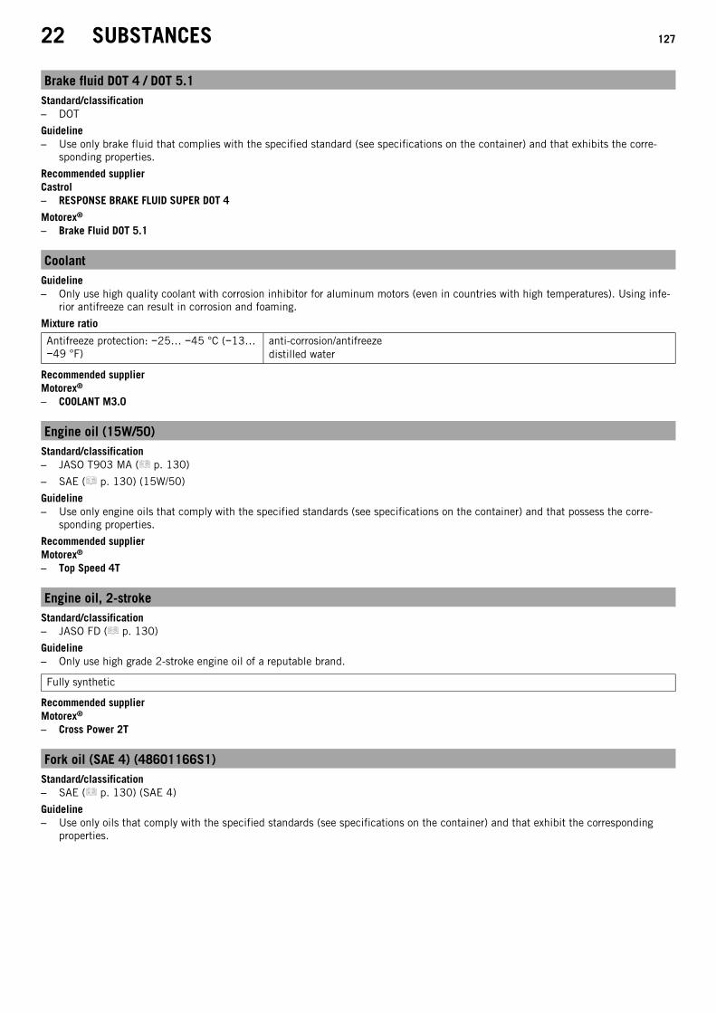
22 SUBSTANCES 127
Brake fluid DOT 4 / DOT 5.1Standard/classification– DOT
Guideline– Use only brake fluid that complies with the specified standard (see specifications on the container) and that exhibits the corre-
sponding properties.
Recommended supplierCastrol– RESPONSE BRAKE FLUID SUPER DOT 4
Motorex®
– Brake Fluid DOT 5.1
CoolantGuideline– Only use high quality coolant with corrosion inhibitor for aluminum motors (even in countries with high temperatures). Using infe-
rior antifreeze can result in corrosion and foaming.
Mixture ratio
Antifreeze protection: −25… −45 °C (−13…−49 °F)
anti-corrosion/antifreezedistilled water
Recommended supplierMotorex®
– COOLANT M3.0
Engine oil (15W/50)Standard/classification– JASO T903 MA ( p. 130)
– SAE ( p. 130) (15W/50)
Guideline– Use only engine oils that comply with the specified standards (see specifications on the container) and that possess the corre-
sponding properties.
Recommended supplierMotorex®
– Top Speed 4T
Engine oil, 2-strokeStandard/classification– JASO FD ( p. 130)
Guideline– Only use high grade 2-stroke engine oil of a reputable brand.
Fully synthetic
Recommended supplierMotorex®
– Cross Power 2T
Fork oil (SAE 4) (48601166S1)Standard/classification– SAE ( p. 130) (SAE 4)
Guideline– Use only oils that comply with the specified standards (see specifications on the container) and that exhibit the corresponding
properties.

22 SUBSTANCES 128
Multi-purpose grease (00062010051)Recommended supplierKlüber Lubrication®
– CENTOPLEX 2 EP
Shock absorber fluid (SAE 2.5) (50180751S1)Standard/classification– SAE ( p. 130) (SAE 2.5)
Guideline– Use only oils that comply with the specified standards (see specifications on the container) and that exhibit the corresponding
properties.
Super unleaded (ROZ 98 / RON 98 / PON 94)Standard/classification– DIN EN 228 (ROZ 98 / RON 98 / PON 94)
Super unleaded (ROZ 95/RON 95/PON 91)Standard/classification– DIN EN 228 (ROZ 95/RON 95/PON 91)
Guideline– Only use unleaded super fuel that matches or is equivalent to the specified fuel grade.
– Fuel with an ethanol content of up to 10 % (E10 fuel) is safe to use.
InfoDo not use fuel containing methanol (e. g. M15, M85, M100) or more than 10 % ethanol (e. g. E15, E25, E85, E100).
Super unleaded (95 octane) mixed with 2-stroke engine oil (1:60)Standard/classification– DIN EN 228
– JASO FD ( p. 130) (1:60)
Mixture ratio
1:60 Engine oil, 2-stroke ( p. 127)Super unleaded (ROZ 95/RON 95/PON 91) ( p. 128)
Recommended supplierMotorex®
– Cross Power 2T
Super unleaded (98 octane) mixed with 2-stroke engine oil (1:40)Standard/classification– DIN EN 228
– JASO FD ( p. 130) (1:40)
Mixture ratio
1:40 Engine oil, 2-stroke ( p. 127)Super unleaded (ROZ 98 / RON 98 / PON 94) ( p. 128)
Recommended supplierMotorex®
– Cross Power 2T

23 AUXILIARY SUBSTANCES 129
Air filter cleanerRecommended supplierMotorex®
– Racing Bio Dirt Remover
Chain cleanerRecommended supplierMotorex®
– Chain Clean
Fuel additiveRecommended supplierMotorex®
– Fuel Stabilizer
High viscosity greaseRecommended supplierSKF®
– LGHB 2
Long-life greaseRecommended supplierMotorex®
– Bike Grease 2000
Motorcycle cleanerRecommended supplierMotorex®
– Moto Clean
Off-road chain sprayRecommended supplierMotorex®
– Chainlube Offroad
Oil for foam air filterRecommended supplierMotorex®
– Racing Bio Liquid Power
Preserving materials for paints, metal and rubberRecommended supplierMotorex®
– Moto Protect
Special cleaner for glossy and matte paint finishes, metal and plastic surfacesRecommended supplierMotorex®
– Quick Cleaner
Universal oil sprayRecommended supplierMotorex®
– Joker 440 Synthetic

24 STANDARDS 130
JASO T903 MADifferent technical development directions required a new specification for 4-stroke motorcycles – the JASO T903 MA Standard. Ear-lier, engine oils from the automobile industry were used for 4-stroke motorcycles because there was no separate motorcycle specifi-cation. Whereas long service intervals are demanded for automobile engines, high performance at high engine speeds are in the fore-ground for motorcycle engines. In most motorcycles, the gearbox and the clutch are lubricated with the same oil as the engine. TheJASO MA Standard meets these special requirements.
SAEThe SAE viscosity classes were defined by the Society of Automotive Engineers and are used for classifying oils according to their vis-cosity. The viscosity describes only one property of oil and says nothing about quality.
JASO FDJASO FD is a classification for a 2-stroke engine oil that was specifically developed for the extreme demands of racing. Thanks to firstrate synthetic esters and specially designed additives, superb combustion is achieved even under extreme operating conditions.

25 LIST OF ABBREVIATIONS 131
Art. no. Article number
ca. circa
cf. compare
e.g. for example
etc. et cetera
i.a. inter alia
no. number
poss. possibly

INDEX 132
INDEX
A
Accessories . . . . . . . . . . . . . . . . . . . . . . . . . . . . . . . . . . . 9
Air filtercleaning . . . . . . . . . . . . . . . . . . . . . . . . . . . . . . . . . 54installing . . . . . . . . . . . . . . . . . . . . . . . . . . . . . . . . . 55removing . . . . . . . . . . . . . . . . . . . . . . . . . . . . . . . . . 54
Air filter boxcleaning . . . . . . . . . . . . . . . . . . . . . . . . . . . . . . . . . 54sealing . . . . . . . . . . . . . . . . . . . . . . . . . . . . . . . . . . 55
Air filter box coverinstalling . . . . . . . . . . . . . . . . . . . . . . . . . . . . . . . . . 53removing . . . . . . . . . . . . . . . . . . . . . . . . . . . . . . . . . 53securing . . . . . . . . . . . . . . . . . . . . . . . . . . . . . . . . . 55
Air suspension AER 48 . . . . . . . . . . . . . . . . . . . . . . . . . . . 31
Antifreezechecking . . . . . . . . . . . . . . . . . . . . . . . . . . . . . . . . . 85
Auxiliary substances . . . . . . . . . . . . . . . . . . . . . . . . . . . . . 9
B
Basic chassis settingchecking with rider's weight . . . . . . . . . . . . . . . . . . . . 31
Batteryinstalling . . . . . . . . . . . . . . . . . . . . . . . . . . . . . . . . . 81recharging . . . . . . . . . . . . . . . . . . . . . . . . . . . . . . . . 82removing . . . . . . . . . . . . . . . . . . . . . . . . . . . . . . . . . 81
Brake discschecking . . . . . . . . . . . . . . . . . . . . . . . . . . . . . . . . . 67
Brake fluidfront brake, adding . . . . . . . . . . . . . . . . . . . . . . . . . . 68rear brake, adding . . . . . . . . . . . . . . . . . . . . . . . . . . 73
Brake fluid levelfront brake, checking . . . . . . . . . . . . . . . . . . . . . . . . 68rear brake, checking . . . . . . . . . . . . . . . . . . . . . . . . . 72
Brake liningsfront brake, checking . . . . . . . . . . . . . . . . . . . . . . . . 69of front brake, changing . . . . . . . . . . . . . . . . . . . . . . 69rear brake, changing . . . . . . . . . . . . . . . . . . . . . . . . . 74rear brake, checking . . . . . . . . . . . . . . . . . . . . . . . . . 73
C
Capacitycoolant . . . . . . . . . . . . . . . . . . . . . . . . . . . . . . . . . 121gear oil . . . . . . . . . . . . . . . . . . . . . . . . . . . . . . 99, 121
Carburetorfloat chamber, emptying . . . . . . . . . . . . . . . . . . . . . . 97idle . . . . . . . . . . . . . . . . . . . . . . . . . . . . . . . . . . . . 93idle speed, adjusting . . . . . . . . . . . . . . . . . . . . . . . . . 93
Carburetor setting . . . . . . . . . . . . . . . . . . . . . . . . . . . . . . 91
Chainchecking . . . . . . . . . . . . . . . . . . . . . . . . . . . . . . . . . 61cleaning . . . . . . . . . . . . . . . . . . . . . . . . . . . . . . . . . 60
Chain guidechecking . . . . . . . . . . . . . . . . . . . . . . . . . . . . . . . . . 61
Chain tensionadjusting . . . . . . . . . . . . . . . . . . . . . . . . . . . . . . . . . 61checking . . . . . . . . . . . . . . . . . . . . . . . . . . . . . . . . . 60
Chassis number . . . . . . . . . . . . . . . . . . . . . . . . . . . . . . . 12Choke . . . . . . . . . . . . . . . . . . . . . . . . . . . . . . . . . . . . . 16
Clutchfluid level, checking/correcting . . . . . . . . . . . . . . . . . . 65fluid, changing . . . . . . . . . . . . . . . . . . . . . . . . . . . . . 65
Clutch lever . . . . . . . . . . . . . . . . . . . . . . . . . . . . . . . . . . 13basic position, adjusting . . . . . . . . . . . . . . . . . . . . . . 64
Compression dampingfork, adjusting . . . . . . . . . . . . . . . . . . . . . . . . . . . . . 39
Compression damping, high-speedshock absorber, adjusting . . . . . . . . . . . . . . . . . . . . . 32
Compression damping, low-speedshock absorber, adjusting . . . . . . . . . . . . . . . . . . . . . 32
Coolantdraining . . . . . . . . . . . . . . . . . . . . . . . . . . . . . . . . . 87refilling . . . . . . . . . . . . . . . . . . . . . . . . . . . . . . . . . . 87
Coolant levelchecking . . . . . . . . . . . . . . . . . . . . . . . . . . . . . . . 85-86
Cooling system . . . . . . . . . . . . . . . . . . . . . . . . . . . . . . . . 84Customer service . . . . . . . . . . . . . . . . . . . . . . . . . . . . . . . 9
D
Difficult operating conditionshigh temperatures . . . . . . . . . . . . . . . . . . . . . . . . . . 22riding at low speeds . . . . . . . . . . . . . . . . . . . . . . . . . 22
Difficult riding conditions . . . . . . . . . . . . . . . . . . . . . . . . . 19dry sand . . . . . . . . . . . . . . . . . . . . . . . . . . . . . . . . . 20low temperature . . . . . . . . . . . . . . . . . . . . . . . . . . . . 23muddy surfaces . . . . . . . . . . . . . . . . . . . . . . . . . . . . 22snow . . . . . . . . . . . . . . . . . . . . . . . . . . . . . . . . . . . . 23wet sand . . . . . . . . . . . . . . . . . . . . . . . . . . . . . . . . . 21wet surfaces . . . . . . . . . . . . . . . . . . . . . . . . . . . . . . 22
E
Electric starter button . . . . . . . . . . . . . . . . . . . . . . . . . . . 13
Enginerunning in . . . . . . . . . . . . . . . . . . . . . . . . . . . . . . . . 19
Engine characteristicauxiliary spring . . . . . . . . . . . . . . . . . . . . . . . . . . . . . 95auxiliary spring, setting . . . . . . . . . . . . . . . . . . . . . . . 96
Engine number . . . . . . . . . . . . . . . . . . . . . . . . . . . . . . . . 12
Engine sprocketchecking . . . . . . . . . . . . . . . . . . . . . . . . . . . . . . . . . 61
Environment . . . . . . . . . . . . . . . . . . . . . . . . . . . . . . . . . . . 7
F
Figures . . . . . . . . . . . . . . . . . . . . . . . . . . . . . . . . . . . . . . 9
Filler capclosing . . . . . . . . . . . . . . . . . . . . . . . . . . . . . . . . . . 14opening . . . . . . . . . . . . . . . . . . . . . . . . . . . . . . . . . . 14
Filling upfuel . . . . . . . . . . . . . . . . . . . . . . . . . . . . . . . . . . . . 27
Foot brake lever . . . . . . . . . . . . . . . . . . . . . . . . . . . . . . . 17basic position, adjusting . . . . . . . . . . . . . . . . . . . . . . 71free travel, checking . . . . . . . . . . . . . . . . . . . . . . . . . 71
Forkair pressure, adjusting . . . . . . . . . . . . . . . . . . . . . . . . 38basic setting, checking . . . . . . . . . . . . . . . . . . . . . . . 37

INDEX 133
Fork legsbleeding . . . . . . . . . . . . . . . . . . . . . . . . . . . . . . . . . 43dust boots, cleaning . . . . . . . . . . . . . . . . . . . . . . . . . 43installing . . . . . . . . . . . . . . . . . . . . . . . . . . . . . . . . . 44removing . . . . . . . . . . . . . . . . . . . . . . . . . . . . . . . . . 43
Fork part number . . . . . . . . . . . . . . . . . . . . . . . . . . . . . . 12
Fork protectorinstalling . . . . . . . . . . . . . . . . . . . . . . . . . . . . . . . . . 45removing . . . . . . . . . . . . . . . . . . . . . . . . . . . . . . . . . 44
Framechecking . . . . . . . . . . . . . . . . . . . . . . . . . . . . . . . . . 63
Front fenderinstalling . . . . . . . . . . . . . . . . . . . . . . . . . . . . . . . . . 49removing . . . . . . . . . . . . . . . . . . . . . . . . . . . . . . . . . 49
Front wheelinstalling . . . . . . . . . . . . . . . . . . . . . . . . . . . . . . . . . 76removing . . . . . . . . . . . . . . . . . . . . . . . . . . . . . . . . . 76
Fuel tankinstalling . . . . . . . . . . . . . . . . . . . . . . . . . . . . . . . . . 58removing . . . . . . . . . . . . . . . . . . . . . . . . . . . . . . . . . 57
Fuel tap . . . . . . . . . . . . . . . . . . . . . . . . . . . . . . . . . . . . 15
Fusechanging the main fuse . . . . . . . . . . . . . . . . . . . . . . . 83
G
Gear oiladding . . . . . . . . . . . . . . . . . . . . . . . . . . . . . . . . . 100changing . . . . . . . . . . . . . . . . . . . . . . . . . . . . . . . . . 98
Gear oil levelchecking . . . . . . . . . . . . . . . . . . . . . . . . . . . . . . . . . 98
H
Hand brake lever . . . . . . . . . . . . . . . . . . . . . . . . . . . . . . 13basic position, adjusting . . . . . . . . . . . . . . . . . . . . . . 67free travel, checking . . . . . . . . . . . . . . . . . . . . . . . . . 67
Handlebar position . . . . . . . . . . . . . . . . . . . . . . . . . . . . . 40adjusting . . . . . . . . . . . . . . . . . . . . . . . . . . . . . . . . . 40
I
Ignition timing mapchanging . . . . . . . . . . . . . . . . . . . . . . . . . . . . . . . . . 94plug-in connector . . . . . . . . . . . . . . . . . . . . . . . . . . . 94
Implied warranty . . . . . . . . . . . . . . . . . . . . . . . . . . . . . . . . 9Intended use . . . . . . . . . . . . . . . . . . . . . . . . . . . . . . . . . . 6
K
Kick starter . . . . . . . . . . . . . . . . . . . . . . . . . . . . . . . . . . 16Kill switch . . . . . . . . . . . . . . . . . . . . . . . . . . . . . . . . . . . 13
L
Lower triple clampinstalling . . . . . . . . . . . . . . . . . . . . . . . . . . . . . . . . . 46removing . . . . . . . . . . . . . . . . . . . . . . . . . . . . . . . . . 45
M
Main fusechanging . . . . . . . . . . . . . . . . . . . . . . . . . . . . . . . . . 83
Main silencerglass fiber yarn filling, changing . . . . . . . . . . . . . . . . . 56installing . . . . . . . . . . . . . . . . . . . . . . . . . . . . . . . . . 56
removing . . . . . . . . . . . . . . . . . . . . . . . . . . . . . . . . . 56
Motorcyclecleaning . . . . . . . . . . . . . . . . . . . . . . . . . . . . . . . . 101lift stand, raising with . . . . . . . . . . . . . . . . . . . . . . . . 42lift stand, removing from . . . . . . . . . . . . . . . . . . . . . . 42
O
Operating substances . . . . . . . . . . . . . . . . . . . . . . . . . . . . . 9Owner's Manual . . . . . . . . . . . . . . . . . . . . . . . . . . . . . . . . 8
P
Plug-in stand . . . . . . . . . . . . . . . . . . . . . . . . . . . . . . . . . 17
Preparing for useadvice on first use . . . . . . . . . . . . . . . . . . . . . . . . . . 18after storage . . . . . . . . . . . . . . . . . . . . . . . . . . . . . 103checks and maintenance work when preparing for use . . 24
Protective clothing . . . . . . . . . . . . . . . . . . . . . . . . . . . . . . 7
R
Radiator cover . . . . . . . . . . . . . . . . . . . . . . . . . . . . . . . . 84installing . . . . . . . . . . . . . . . . . . . . . . . . . . . . . . . . . 84removing . . . . . . . . . . . . . . . . . . . . . . . . . . . . . . . . . 85
Rear sprocketchecking . . . . . . . . . . . . . . . . . . . . . . . . . . . . . . . . . 61
Rear wheelinstalling . . . . . . . . . . . . . . . . . . . . . . . . . . . . . . . . . 78removing . . . . . . . . . . . . . . . . . . . . . . . . . . . . . . . . . 77
Rebound dampingfork, adjusting . . . . . . . . . . . . . . . . . . . . . . . . . . . . . 39shock absorber, adjusting . . . . . . . . . . . . . . . . . . . . . 33
Riding sagadjusting . . . . . . . . . . . . . . . . . . . . . . . . . . . . . . . . . 36
Rubber gripchecking . . . . . . . . . . . . . . . . . . . . . . . . . . . . . . . . . 64
S
Safe operation . . . . . . . . . . . . . . . . . . . . . . . . . . . . . . . . . 7
Seatmounting . . . . . . . . . . . . . . . . . . . . . . . . . . . . . . . . 53removing . . . . . . . . . . . . . . . . . . . . . . . . . . . . . . . . . 52
Service . . . . . . . . . . . . . . . . . . . . . . . . . . . . . . . . . . . . . . 9Service hour counter . . . . . . . . . . . . . . . . . . . . . . . . . . . . 17
Shift lever . . . . . . . . . . . . . . . . . . . . . . . . . . . . . . . . . . . 16basic position, adjusting . . . . . . . . . . . . . . . . . . . . . . 95basic position, checking . . . . . . . . . . . . . . . . . . . . . . 95
Shock absorbercompression damping, general . . . . . . . . . . . . . . . . . . 31installing . . . . . . . . . . . . . . . . . . . . . . . . . . . . . . . . . 51removing . . . . . . . . . . . . . . . . . . . . . . . . . . . . . . . . . 50riding sag, checking . . . . . . . . . . . . . . . . . . . . . . . . . 35spring preload, adjusting . . . . . . . . . . . . . . . . . . . . . . 35static sag, checking . . . . . . . . . . . . . . . . . . . . . . . . . 35
Shock absorber article number . . . . . . . . . . . . . . . . . . . . . 12Side stand . . . . . . . . . . . . . . . . . . . . . . . . . . . . . . . . . . . 17Spare parts . . . . . . . . . . . . . . . . . . . . . . . . . . . . . . . . . . . 9
Spoke tensionchecking . . . . . . . . . . . . . . . . . . . . . . . . . . . . . . . . . 79
Start number plateinstalling . . . . . . . . . . . . . . . . . . . . . . . . . . . . . . . . . 49

INDEX 134
removing . . . . . . . . . . . . . . . . . . . . . . . . . . . . . . . . . 49
Starting . . . . . . . . . . . . . . . . . . . . . . . . . . . . . . . . . . . . 24
Steering head bearinggreasing . . . . . . . . . . . . . . . . . . . . . . . . . . . . . . . . . 48
Steering head bearing playadjusting . . . . . . . . . . . . . . . . . . . . . . . . . . . . . . . . . 48checking . . . . . . . . . . . . . . . . . . . . . . . . . . . . . . . . . 47
Storage . . . . . . . . . . . . . . . . . . . . . . . . . . . . . . . . . . . 102
Swingarmchecking . . . . . . . . . . . . . . . . . . . . . . . . . . . . . . . . . 63
T
Technical datacapacities . . . . . . . . . . . . . . . . . . . . . . . . . . . . . . . 121carburetor . . . . . . . . . . . . . . . . . . . . . . . . . . . . . . . 112chassis . . . . . . . . . . . . . . . . . . . . . . . . . . . . . . . . . 121chassis tightening torques . . . . . . . . . . . . . . . . . . . . 126electrical system . . . . . . . . . . . . . . . . . . . . . . . . . . 122engine . . . . . . . . . . . . . . . . . . . . . . . . . . . . . . . . . 106engine tightening torques . . . . . . . . . . . . . . . . . . . . 108fork . . . . . . . . . . . . . . . . . . . . . . . . . . . . . . . . . . . 122shock absorber . . . . . . . . . . . . . . . . . . . . . . . . . . . . 123tires . . . . . . . . . . . . . . . . . . . . . . . . . . . . . . . . . . . 122
Throttle cable playadjusting . . . . . . . . . . . . . . . . . . . . . . . . . . . . . . . . . 90checking . . . . . . . . . . . . . . . . . . . . . . . . . . . . . . . . . 90
Throttle cable routingchecking . . . . . . . . . . . . . . . . . . . . . . . . . . . . . . . . . 63
Throttle grip . . . . . . . . . . . . . . . . . . . . . . . . . . . . . . . . . . 13
Tire air pressurechecking . . . . . . . . . . . . . . . . . . . . . . . . . . . . . . . . . 79
Tire conditionchecking . . . . . . . . . . . . . . . . . . . . . . . . . . . . . . . . . 79
Transport . . . . . . . . . . . . . . . . . . . . . . . . . . . . . . . . . . . 26Troubleshooting . . . . . . . . . . . . . . . . . . . . . . . . . . . 104-105Type label . . . . . . . . . . . . . . . . . . . . . . . . . . . . . . . . . . . 12
U
Use definition . . . . . . . . . . . . . . . . . . . . . . . . . . . . . . . . . 6
V
View of vehiclefront left . . . . . . . . . . . . . . . . . . . . . . . . . . . . . . . . . 10rear right . . . . . . . . . . . . . . . . . . . . . . . . . . . . . . . . . 11
W
Warranty . . . . . . . . . . . . . . . . . . . . . . . . . . . . . . . . . . . . . 9Work rules . . . . . . . . . . . . . . . . . . . . . . . . . . . . . . . . . . . 7

*3213471en*3213471en
05/2016
KTM Sportmotorcycle GmbH5230 Mattighofen/Austriahttp://www.ktm.com
Photo: Mitterbauer/KTM