owner’smanual with installation instructions - … requires removal of the transmission ... ed....
TRANSCRIPT
Banks BilletTM Torque Converter2001-2008 Chevy/GMC Duramax Allison Transmission
THIS MANUAL IS FOR USE WITH KITS 72510
Owner’sManualwith Installation Instructions

2 96732 v.2.0
1. Familiarize yourself with the installa-tion procedure by reading the installation manual before starting work.
2. Throughout this manual, the left side of the vehicle refers to the driver’s side, and the right side refers to the passen-ger’s side.
3. Disconnect the negative (ground) cable from the battery (or batteries, if there are two) before beginning work.
4. Route and tie wires and hoses a minimum of 6 inches away from exhaust heat, moving parts and sharp edges. Clearance of 8 inches or more is recommended where possible.
5. During installation, keep your work area and tools clean to avoid possible entry of dirt into the drivetrain.
6. When raising the vehicle, support it on properly weight-rated safety stands, ramps or a commercial hoist. Follow the manufacturer’s safety precautions. Take care to balance the vehicle to prevent it from slipping or falling. When using ramps, be sure the front wheels are centered squarely on the topsides. When raising the front of the vehicle, set the parking brake and block the rear wheels. When raising the back of the vehicle, be sure the vehicle is on level ground and the front wheels are securely blocked.
Caution! Do not use floor jacks to support the vehicle while work-ing under it. Do not support the vehicle using concrete blocks, masonry or any other item not intended specifically for this use.
7. Installing the Banks Torque Convert-er requires removal of the transmission from the vehicle. Heavy tooling such as a transmission jack and an automotive hoist or ample-height jack stands are required. Professional installation by a properly equipped shop is recommend-ed. Failure to follow all installation instructions during Torque Converter install can result in bodily injury and/or expensive damage to the transmission and surrounding components.
8. The transmission and torque con-verter must be removed as an assem-bly to avoid damage to the converter drive plate, pump bushing and oil seal.
9. Before installing the Banks Torque Converter, verify that your transmis-sion is in good operating condition. Transmission problems such as harsh or delayed engagement when shift-ing into Drive or Reverse, no Drive or Reverse range, erratic shifting, grating or scraping noises, or lack of up and/or downshifting can lead to torque con-verter damage. If necessary, have your transmission repaired or overhauled before installing the converter.
General Installation Practices
>>>>

96732 v.2.0 3
Tools Required: • 3 ⁄ 8” and 1⁄2” drive ratchets with
metric sockets including 1⁄2” and 3 ⁄ 8” drive extension
• Metric combination or open-end wrenches
• Standard and Phillips head screwdrivers
• Standard and needle-nose pliers
• Clean shop towels or rags
• Transmission hoist
• Floor jack
• C-clamp
• Drain pan
• GM Goodwrench DEXRON® VI ATF fluid (See manufacturers recommendations for your specific model)
• 320-400 grit sandpaper
• Measuring ruler
• Pry bar or channel lock pliers
• Grease pen
• Inch-pound and foot-pound torque wrenches
Highly recommended tools and supplies:• Penetrating oil or light lubricant
spray
• Transmission fluid filter
• Transmission pan gasket
• Torsion Bar Removal Tool (Kent Moore PN J36202)
Notice To Installer: Banks recommends replacing your transmission fluid, transmission fluid filter and transmission pan gasket. Failure to service transmission may result in torque converter damage.

General Figure 1
Description Description
1 Torque Converter 8 Transmission Oil Pan
2 Turbine Shaft 9 Input speed sensor
3 Drive Shaft Output 10 Turbine speed sensor
4 Torque Converter Housing 11 Output speed sensor
5 Fuel Line Retaining nut 12 Park/neutral position Switch
6 Fill tube 13 Main electrical connector
7 Transmission Cooler Lines
4 96732 v.2.0

96732 v.2.0 5

6 96732 v.2.0
Torque Converter Removal1. Disconnect the negative (ground) cable from the battery (if there is more than one battery, disconnect both negative cables). Secure the cable so it cannot accidentally come in con-tact with the post.
2. Raise the vehicle high enough to remove the transmission and support it securely with properly weight-rated safety stands, ramps or a commercial hoist. Take care to balance the vehicle to prevent it from slipping or falling. When using ramps, be sure the wheels are centered squarely on the topsides. Set the parking brake and securely block the wheels that are on the ground.
CAUTION: DO NOT WORK UNDER ANY VEHICLE SUPPORTED ONLY
BY A JACK. SEVERE INJURY MAY RESULT.
3. Carefully remove the Banks Torque Converter from the shipping container. Be careful not to damage the shipping container as it will be used to return the factory torque converter to Gale Banks Engineering.
4. To avoid pump seal damage dur-ing converter installation, inspect the Banks Torque Converter hub and hub drive notches for sharp edges, burrs, scratches or nicks. It may be neces-sary to polish hub and/or notches with 320/400 grit sandpaper and crocus cloth.
CAUTION: Make sure to cover the drive hub entry with a clean rag to prevent any contaminants from entering the torque converter. Clean any contaminants from
Installation procedure
Figure 2

96732 v.2.0 7
the converter hub and hub drive notches off before installing the torque converter into the trans-mission or damage may result.
5. Remove the factory front catalytic converter hanger pin from the Exhaust hanger rubber grommet. See Figure 2.
Note: Loosen the exhaust clamps and disconnect the exhaust components to ease the removal of the hanger pin from the rubber grommet and to make room for starter and transmission removal.
Note: Spray lubricant may assist in hanger pin removal.
6. Remove the Exhaust hanger from the right side of the transmission.
7. Torsion Bar Removal
A. Install the Torsion Bar Removal Tool to the Adjustment Arm and the Cross Member. See Figure 3.
Note: There is a notch on top of the Cross Member to properly sit the Removal Tool.
Figure 3

8 96732 v.2.0
B. Increase the tension on the Adjustment Arm until the load is removed from the Adjustment bolt and Adjuster nut.
C. Remove the Adjustment bolt and Adjuster nut.
-Important- Mark the location of the Adjustment bolt and Adjuster nut before removing to help with alignment during re-installation.
D. Remove the Removal Tool to al-low the Torsion Bar to unload.
E. Remove the Adjustment Arm by sliding the Torsion Bar forward until it clears the Cross Member.
Note: Once the Torsion Bar is re-moved, the Adjustment Arm is free to move, take care to support the Adjustment Arm.
F. Remove the Torsion Bars and Adjustment Arms from the vehicle.
Note: Mark the position of the Tor-sion Bars as the left and right bar are different.
G. Remove the Cross Member bolts from the weld nuts and remove the member by lifting and moving it to the rear of the vehicle.
8. Remove the starter motor to access converter bolts. Retain the hardware for reassembly.
Note: To provide better access to the starter, the right front wheel and wheel housing may be removed.
9. Rotate the crankshaft bolt in front of the engine with a large 36mm wrench to access the torque converter bolts thru the starter opening. Remove torque converter bolts. See Figure 4.
Figure 4

96732 v.2.0 9
Figure 5
Note: Only rotate the engine clockwise. Rotating the engine counterclockwise may loosen the crankshaft balancer bolt.
10. Mark the rear propeller shaft and axle yokes for assembly alignment, then disconnect and remove the pro-peller shaft. (It is common for transmis-sion fluid to drain from the rear of the transmission after driveshaft removal.)
11. For 4 x 4 models - Mark the front propeller shaft and axle yokes for assembly alignment, then disconnect the front propeller shaft from the front axle pinion yoke.
12. Remove the fuel line retainer bolts on the driver side of the transmission.
13. Disconnect the park/ neutral posi-tion switch, turbine speed sensor, and the output and input speed sensor wire
connectors. Disconnect the transmis-sion main electrical connector. Secure all wires away from transmission.
14. Disconnect the shift cable from the selector lever ball stud and remove the cable from the bracket. Secure cable away from transmission.
15. Disconnect transmission fluid cooler lines by removing the retain-ing clips and carefully pulling the lines out of the transmission fittings. Secure lines away from the transmission. Plug the cooler lines fittings in the transmis-sion case. See Figure 5.
16. Remove the fill tube nuts from the converter housing and pull the tube out of the transmission. Retain fill tube O-ring and hardware for re-assembly. Plug the fill tube fitting in the transmission case. See Figure 6.
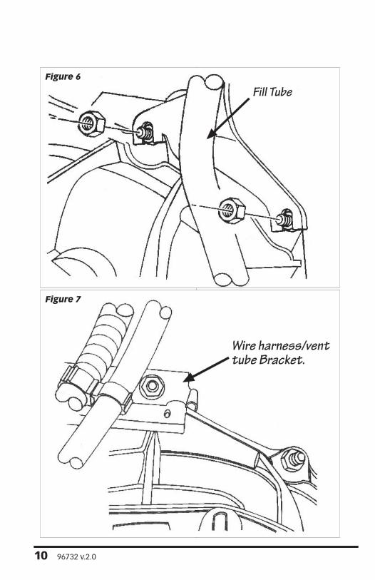
Figure 7
Figure 6
10 96732 v.2.0

17. Remove the wire harness/vent tube bracket nut from the top of the converter housing stud. See Figure 7.
18. Support the rear of the engine with a jack, engine hoist or safety stands. Raise the transmission slightly with a transmission jack to relieve load on the cross member support.
19. Remove the bolts securing rear support, transmission cushion and cross member.
20. Remove the bolts attaching the cross member to the frame and re-move the cross member.
21. Remove all the torque converter housing bolts and studs and retain for reassembly. Carefully slide the trans-mission and torque converter assembly rearward. Disengage torque converter hub from the end of the crankshaft.
WARNING: Torque Converter can slide off the turbine shaft. Secure the converter when removing the transmission and torque convert-er assembly from the engine.
22. Lower the transmission and re-move it from under the vehicle.
23. Once the transmission and torque converter assembly are removed, place a suitable drain pan under the convert-er housing end of the transmission.
24. Measure from the mounting lugs on the torque converter to the trans-mission mounting face. See Figure 8.
-Important- The distance from the torque converter mounting lugs to the face on the transmission mounting face must be recorded. This will insure proper installation of the Banks Torque Converter.
Figure 8
96732 v.2.0 11
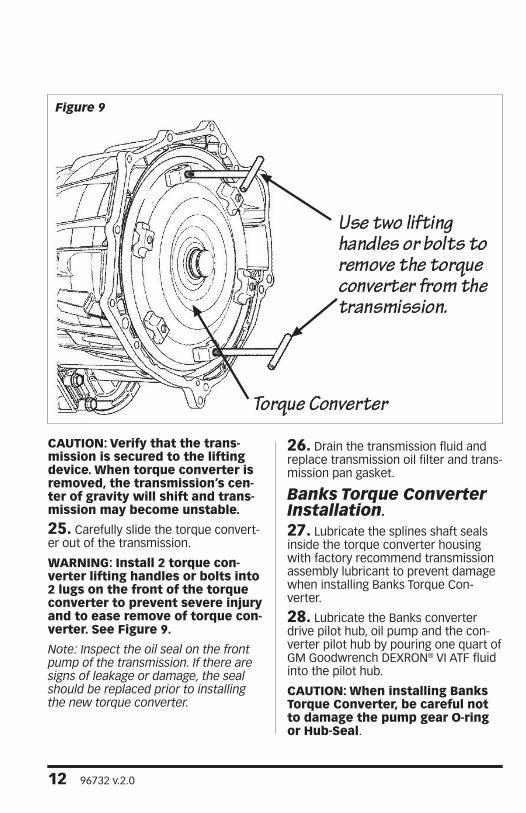
CAUTION: Verify that the trans-mission is secured to the lifting device. When torque converter is removed, the transmission’s cen-ter of gravity will shift and trans-mission may become unstable.
25. Carefully slide the torque convert-er out of the transmission.
WARNING: Install 2 torque con-verter lifting handles or bolts into 2 lugs on the front of the torque converter to prevent severe injury and to ease remove of torque con-verter. See Figure 9.
Note: Inspect the oil seal on the front pump of the transmission. If there are signs of leakage or damage, the seal should be replaced prior to installing the new torque converter.
26. Drain the transmission fluid and replace transmission oil filter and trans-mission pan gasket.
Banks Torque Converter Installation.
27. Lubricate the splines shaft seals inside the torque converter housing with factory recommend transmission assembly lubricant to prevent damage when installing Banks Torque Con-verter.
28. Lubricate the Banks converter drive pilot hub, oil pump and the con-verter pilot hub by pouring one quart of GM Goodwrench DEXRON® VI ATF fluid into the pilot hub.
CAUTION: When installing Banks Torque Converter, be careful not to damage the pump gear O-ring or Hub-Seal.
Figure 9
12 96732 v.2.0

29. Align and carefully rotate the Banks Torque Converter to engage the turbine shaft splines to the converter drive pilot hub. Continue rotating push-ing the converter inward to engage the stator shaft splines to the stator race and the drive flats on the converter to the oil pump drive gear. Be sure the converter drive pilot hub is fully seated in pump gears.
30. Check converter seating with a ruler and straightedge (Figure 8).
Note: Converter is properly seated when the distance from the lugs to the mounting face is the same as recorded measurement taken before removal of factory torque converter. Refer to measurement record in step 24.
31. Raise the transmission and align the converter with the drive plate.
32. Move the transmission towards the engine and raise/tilt the transmis-sion to align the converter housing with alignment dowels.
33. Seat the front converter hub into the crankshaft by aligning the transmis-sion over the alignment dowels.
Note: Check to see if torque converter will rotate smoothly and will not bind with the crankshaft.
34. Install the factory bolts and studs through the converter housing and into engine.
35. Reinstall the transmission cross member to the vehicle frame. Lower the transmission onto the cross mem-ber to the vehicle frame. Install and tighten the bolts attaching the trans-mission mount to the cross member cushion.
36. Reinstall the wire harness/vent tube bracket and nut to the top of the converter housing.
37. Reinstall the fill tube and nuts to the converter housing.
38. Install the park/neutral position switch, turbine speed sensor, and the output and input speed sensor connec-tor. Reconnect the transmission main electrical connector.
39. Shift the park/neutral position switch forward to put the transmission in the park position. Connect the shift cable over the selector lever ball stud and connect the cable to the bracket.
40. Rotate the crankshaft bolt in front of the engine to install torque con-verter bolts thru the starter opening. Reinstall the torque converter bolts and torque to 44 ft-lbs.
41. Reinstall the rear propeller shaft. Be sure to realign the marks on propel-ler shaft and yoke.
42. For 4x4 models - Reconnect the Front propeller shaft to the front axle pinion yoke and realign the marks on the propeller shaft and yoke.
43. Reinstall the starter motor.
44. Reinstall cooler line bracket and connect the cooler lines to the trans-mission.
45. Torsion Bar installation
A. Slide the Cross Member over the weld nuts and drop into place. Reinstall factory bolts and tighten to 70 ft-lbs.
B. Slide the Torsion Bar into the lower control arm. Slide the Adjust-ment Arm into the Cross Member. While holding the Adjustment Arm in place, slide the Torsion Bar from the lower control arm rearward into the Cross Member. Make sure the Torsion Bar slides into the Adjust-ment Arm and is properly inserted.
96732 v.2.0 13

C. Install the Torsion Bar Removal Tool to the Adjustment Arm and the Cross Member. Make sure the Re-moval Tool sits on the notch on top of the Cross Member. See Figure 2.
D. Add tension on the Adjustment Arm until the Adjustment bolt and Adjuster nut can be installed.
E. Install the Adjustment bolt and Adjuster nut and adjust the bolt and nut to realign to the marks made during removal process.
Note: Refer to factory recommen-dation on Torsion Bar adjustment.
F. Remove the Removal Tool.
46. Reinstall exhaust hanger and reconnect the exhaust hanger pin into the rubber grommet.
47. Reconnect exhaust components and clamps
48. Reconnect the fuel line retainer bolts on the driver side of transmission.
49. Verify that all previously removed components are reconnected, all tools used are accounted for and all bolts are tightened to manufacture specifica-tions.
50. Fill the transmission with the fac-tory recommended GM Goodwrench DEXRON® VI ATF.
CAUTION: DO NOT overfill trans-mission fluid. Fill transmission with 6 quarts then start your vehicle and check fluid level. Add ATF fluid as needed.
51. Reconnect the battery cable(s).
52. Start the vehicle and allow engine to reach normal operating temperatures. With the vehicle lightly loaded, accelerate gently and allow the torque converter to lock and unlock a minimum of fifteen (15) times. Monitor transmission temperatures and stall speed to verify the torque converter is operating normally. Check transmission fluid level and add ATF fluid if needed. Installation of the Banks Torque Con-verter is now complete.
14 96732 v.2.0

You will notice that you have been charged a $250.00 refundable core charge for your Banks Torque Convert-er. In order to receive a refund on the core charge you must send us a good rebuildable core. Please follow these important instructions.
1. Do not discard or destroy the ship-ping container that your new torque converter came in.
2. After installation of your new torqueconverter, DRAIN ALL FLUID from your old torque converter by allowing it to sit upside-down in a suitable drain pan or container overnight.
CAUTION: Failure to properly drain the converter may result in ship-ping refusal or other consequenc-es related to shipping hazardous material.
3. Install supplied plug on old torqueconverter input hub and wrap it in the supplied plastic bag.
4. Pack the torque converter into theBanks shipping container. If applicable, place the foam insulation around the torque converter to prevent damage during shipping.
5. Reseal the shipping container. Verifythat the Torque Converter is secure in the shipping container.
6. Locate the return shipping labelincluded in the Banks Torque Converter package and affix it to the outside of the shipping container so that it com-pletely covers the previous shipping label.
To receive a core charge refund, complete the following steps