owners operating manual… · owners operating manual congratulations on your purchase of a quality...
TRANSCRIPT

OWNERS OPERATING MANUAL
CONGRATULATIONS ON YOUR PURCHASE OF A QUALITY WELDCORP WELDER MANUFACTURED IN ITALY, IT WILL PROVIDE YEARS OF RELIABLE OPERATION.

SAFETY INSTRUCTIONS Page 4
DESCRIPTION OF MACHINES Page 6
MIG 100 Page 6
MIG 120 Page 7
MIG 160 Page 8
ASSEMBLY INSTRUCTIONS Page 9
SET UP OF THE WELDER (GAS AND GASLESS) Page 10
OPERATION Page 11
MOUNTING OF THE REFILL WIRE SPOOL Page11
OPERATION—GAS OR NO GAS APPLICATION Page 11
KEY POINTS TO FEEDING THE WELDING WIRE Page 12
FEEDING THE WELDING WIRE Page 14
FITTING THE GAS BOTTLE Page 16
WELDING BASICS Page 17
THERMAL OVERLOAD Page 17
WELDING INFORMATION Page 18
WIRE EXTENSIONS (WIRE STICK OUT) Page 19
STARTING THE ARC Page 20
TECHNIQUES Page 20
WELDING EXAMPLES Page 21
TROUBLE SHOOTING GUIDE Page 22
SPARE PARTS
MIG 100 Page 24
MIG 120 / 160 Page 26
WARRANTY Page 30
WARRANTY FORM Page 31
CONTACT DETAILS Page 32
T A B L E O F C O N T E N T S

Page 4
When u s in g power equ i pmen t , ba s i c sa f e ty p recau t ion s shou l d a l ways be fo l l owed to redu ce th e r i s k o f f i r e , e l ec t r i c sh o ck and per sona l i n ju ry , i n c lu d in g th e f o l l ow ing . I f u sed co r rec t l y , we l d -e r s po se l i t t l e r i s k t o th e opera to r ; h owever , ca re shou l d a l ways be ta ken to en su re sa f e ty and p roper pe r f o rmance . R ead a l l owner ’ s opera t i n g i n s t ru c t i on s be f o re a t t empt i n g to opera te a ny p rodu c t . F OR SA F E OPE R AT I O N:
KEEP THE WORK AREA CLEAN: C lu t t e red
wo rk i n g a rea s ( in doo r and ou tdoo r ) i n vi t e in ju r i es.
CONSIDER THE WORK ENVIRONMENT: Don ’ t expose power
equ i pmen t t o ra i n . Don ’ t u se we l d in g equ i pmen t i n damp o r wet l o ca t ion s . Keep th e wo rk a rea we l l l i t . Don ’ t u se we l d i n g equ i pmen t in th e p resen ce o f f l ammabl e l i qu i ds or ga ses .
GUARD AGAINST E LECTR IC SHOCK: Avo i d body con ta c t th e
g rounded su r f a ces ( e .g . p i pes , r a d i a to r , a nd e l ec tr i c a l a pp l i -a n ces ) .
KEEP CHILDREN AND V IS ITORS AWAY: Keep ch i l d ren , in -
f i rmed per son s and v i s i t o r s away f rom th e a rea o f opera -t i on . Do no t l e t ch i l d ren , i n f i rmed per son s o r v i s i t o r s t ou ch equ i pmen t o r ex ten s i on cabl es .
STORE IDLE TOOLS: When power equ i pmen t i s n o t i n u se ,
keep th em i n a d ry , h i gh o r l o cked a rea , ou t o f r ea ch o f ch i l d ren .
WEAR SAFETY GLASSES: A l ways wea r sa f e ty gogg l es o r
o th er su i t a bl e eye p ro tec t i on when u s in g we l d i n g equ i p -men t .
SECURE WORK: U se c lamps o r a v i ce whenever po ss i b l e t o
secu re wo rk .
DON’T OVERREACH: Keep p roper f o o t i n g and ba la n ce a t a l l
t i mes .
S A F E T Y I N S T R U C T I O N S
Page 5
DRESS PROPERLY: DO NOT wea r l oo se c lo th i n g or j ewe l l e ry .
They can be caugh t i n movi ng pa r t s . Wea r p ro tec t i ve h a i r cover i n g to cover l ong h a i r , and g lo ves a nd n on - s l i p fo o t -wea r i s r ecommended when wo rk i n g ou tdoo rs .
TAKE CARE OF CABLES: Never ca r ry we l d i n g equ i pmen t by
th e cab l e and n ever pu l l t h e cab l e t o di s connec t i t f r om a so cke t . K eep cab l es away f rom hea t , o i l and sha rp edges . R ep l a ce damaged cabl es .
DISCONNECT TOOLS: D i s connec t we l d i n g equ i pmen t when
no t i n u se , be f o re se rv i c i n g , a nd when chang in g a ccesso r i es su ch a s b la des , b i t s and cu t te r s .
AVOID UNINTENTIONAL OPERATION: Don ’ t ca r ry p l u gged i n
we l d i n g equ i pmen t w i th a f i n ger on th e swi t ch . Be su re th a t th e sw i t ch i s o f f when pl u ggi n g i n .
OUTDOOR USE EXTENSION CABLES: When e l ec t r i c power
equ i pmen t i s u sed ou tdoo rs , on l y u se ex ten s i on cab l es ma rked a s su i ta b l e fo r ou tdoo r u se .
STAY ALERT: Wa tch wha t you a re do i n g . U se common sen se .
Do no t opera te we l der s when you a re t i r ed o r under th e i n -f l u en ce o f a l coho l o r d rugs .
CHECK DAMAGED PARTS: Be f o re u s in g we l d in g equ i pmen t ,
pa r t s th a t a re damaged shou l d be ca re f u l l y ch ecked to de-te rm i ne th a t th ey w i l l o pera te p roper l y and per f o rm th e i r i n tended fun c t i on . Any pa r t th a t i s damaged shou l d be p rop-er l y r epa i r ed o r r e p l a ced by a n au tho r i zed se r v i ce a gen t . Have de f ec t sw i t ch es rep l a ced b y a n au tho r i zed r epa i r a gen t . Do n o t opera te power equ i pmen t i f i t c a nno t be tu rn ed o f f a nd on by th e swi t ch .
REPAIR OF POWER EQU IPMENT BY EXPERTS: Power e qu i p -
men t i s bu i l t i n a c co rdan ce w i th re l evan t sa f e ty a u tho r i t y r equ i remen ts . The repa i r o f power equ i pmen t m us t on l y be ca r r i ed ou t by exper t s ; n on -exper t r epa i r s may cau se con -s i derab l e danger f o r th e u ser a nd vo i d wa r ran ty .

FEATURES
ANTI-SHOCK CLAMP 10 AMP SINGLE PHASE ACCESSORIES INCLUDED THERMOSTATIC CONTROL ANTI-SCRATCH PAINT ACCESSORIES ASSEMBLES PORTABLE EUROPEAN CONFORMITY WIREFEEDER 2 REELS SPEED INDICATOR WIRE SPEED REGULATOR DIRECT CONNECTION FLUX CORED WIRE TORCH Page 6
D E S C R I P T I O N O F M A C H I N E S
These models are portable MIG Gas and Gasless Welders which are compact. The robust format makes them a versatile and efficient for a variety of uses. The weld-ers compliance to current regulations and the optimum quality of materials used will ensure a long working life with complete safety.
M I G 1 0 0 G A S L E S S SPECIFICATIONS
Mains Voltage 230V Welding Current 35—100 Amps Duty Cycle 20% 100 Amps Wire 0.8—1.0 mm Weight 13.8 Kg
ACCESSORIES
Electrode Holder
Work Clamp
Hand Held Face Mask
Combination Chipping Hammer with Wire Brush
Instructional DVD

Page 7
M I G 1 2 0 G A S / G A S L E S S
SPECIFICATIONS
Mains Voltage 230—400V Welding Current 40—170 Amps Minimum Electrode 1.6 mm Maximum Electrode 4.0 mm Weight 26.5 Kg
ACCESSORIES
Torch Cable
Work Clamp
Hand Held Face Mask
Combination Chipping
Hammer with Wire Brush
Instructional DVD
Gasless Welding Wire
FEATURES
ANTI-SHOCK CLAMP 10 AMP SINGLE PHASE
THERMOSTATIC CONTROL EUROPEAN CONFORMITY
ANTI-SCRATCH PAINT FLUX CORED WIRE
PORTABLE WIRE SPEED REGULATOR
FAN WIREFEEDER 2 REELS
DIRECT CONNECTION TORCH NO VOLTAGE ON TORCH
POWER GENERATOR SAFE
NOTE: This welder is a dual purpose gas / gasless machine. Refer to the table on page 18 for the gas required.

Page 8
M I G 1 6 0 G A S / G A S L E S S
FEATURES
ANTI-SHOCK CLAMP 10 AMP SINGLE PHASE
THERMOSTATIC CONTROL EUROPEAN CONFORMITY
ANTI-SCRATCH PAINT FLUX CORED WIRE
PORTABLE WIRE SPEED REGULATOR
FAN WIREFEEDER 2 REELS
DIRECT CONNECTION TORCH NO VOLTAGE ON TORCH
POWER GENERATOR SAFE WHEEL KIT
NOTE: This welder is a dual purpose gas / gasless machine. Refer to the table on page 19 for the gas required.
SPECIFICATIONS
Mains Voltage 230—400V Welding Current 40—170 Amps Minimum Electrode 1.6 mm Maximum Electrode 4.0 mm Weight 34.7 Kg
ACCESSORIES
Torch Cable
Work Clamp
Hand Held Face Mask
Combination Chipping
Hammer with Wire Brush
Instructional DVD
Gasless Welding Wire
Mini Regulator

A S S E M B L Y I N S T R U C T I O N S
For the MIG 160
Slide the right wheel and axle into position. At-tach the left wheel onto the axle and insert the R Clips to retain wheels.
For the MIG 160
Fit the trolley base into position and secure with screws.
For the MIG 120 and MIG 160
Slide the handle into the grooves on top of the machine and secure with screws.
For the MIG 160
Slide the handle extension through the handle and secure with screw.
Page 9
For the MIG 160
Attach gas bottle support and secure with screws.

Page 10
S E T U P O F T H E W E L D E R — G A S L E S S
WELDING MACHINE
ARC
WORK
GROUND EARTH CABLE
MIG TORCH
WIRE FEED HOSE
S E T U P O F T H E W E L D E R — G A S
WELDING MACHINE
ARC
WORK
GROUND EARTH CABLE
MIG TORCH
WIRE FEED HOSE
GAS
GAS HOSE
Page 11
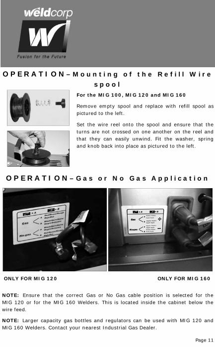
O P E R A T I O N – M o u n t i n g o f t h e R e f i l l W i r e
s p o o l For the MIG 100, MIG 120 and MIG 160
Remove empty spool and replace with refill spool as pictured to the left.
Set the wire reel onto the spool and ensure that the turns are not crossed on one another on the reel and that they can easily unwind. Fit the washer, spring and knob back into place as pictured to the left.
NOTE: Larger capacity gas bottles and regulators can be used with MIG 120 and MIG 160 Welders. Contact your nearest Industrial Gas Dealer.
O P E R A T I O N – G a s o r N o G a s A p p l i c a t i o n
NOTE: Ensure that the correct Gas or No Gas cable position is selected for the MIG 120 or for the MIG 160 Welders. This is located inside the cabinet below the wire feed.
ONLY FOR MIG 120 ONLY FOR MIG 160
Page 12
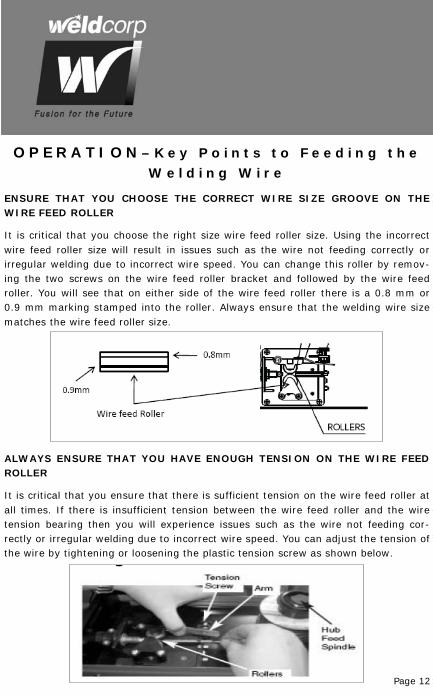
O P E R A T I O N – K e y P o i n t s t o F e e d i n g t h e W e l d i n g W i r e
ENSURE THAT YOU CHOOSE THE CORRECT WIRE SIZE GROOVE ON THE WIRE FEED ROLLER
It is critical that you choose the right size wire feed roller size. Using the incorrect wire feed roller size will result in issues such as the wire not feeding correctly or irregular welding due to incorrect wire speed. You can change this roller by remov-ing the two screws on the wire feed roller bracket and followed by the wire feed roller. You will see that on either side of the wire feed roller there is a 0.8 mm or 0.9 mm marking stamped into the roller. Always ensure that the welding wire size matches the wire feed roller size.
ALWAYS ENSURE THAT YOU HAVE ENOUGH TENSION ON THE WIRE FEED ROLLER
It is critical that you ensure that there is sufficient tension on the wire feed roller at all times. If there is insufficient tension between the wire feed roller and the wire tension bearing then you will experience issues such as the wire not feeding cor-rectly or irregular welding due to incorrect wire speed. You can adjust the tension of the wire by tightening or loosening the plastic tension screw as shown below.
Page 13
O P E R A T I O N – K e y P o i n t s t o F e e d i n g t h e W e l d i n g W i r e
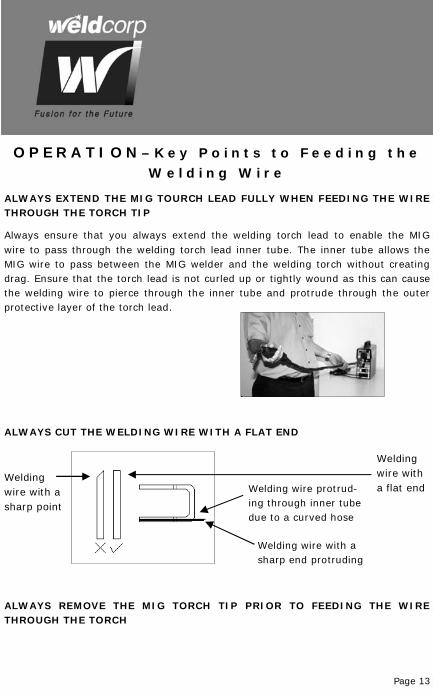
ALWAYS EXTEND THE MIG TOURCH LEAD FULLY WHEN FEEDING THE WIRE THROUGH THE TORCH TIP
Always ensure that you always extend the welding torch lead to enable the MIG wire to pass through the welding torch lead inner tube. The inner tube allows the MIG wire to pass between the MIG welder and the welding torch without creating drag. Ensure that the torch lead is not curled up or tightly wound as this can cause the welding wire to pierce through the inner tube and protrude through the outer protective layer of the torch lead.
ALWAYS CUT THE WELDING WIRE WITH A FLAT END
Welding wire with a sharp point
Welding wire with a flat end
Welding wire with a sharp end protruding
Welding wire protrud-ing through inner tube due to a curved hose
ALWAYS REMOVE THE MIG TORCH TIP PRIOR TO FEEDING THE WIRE THROUGH THE TORCH

Page 14
O P E R A T I O N – F e e d i n g t h e W e l d i n g W i r e
For the MIG 100, MIG 120 and MIG 160
Unwind the welding wire and feed it through the plastic guide tube.
For the MIG 100, MIG 120 and MIG 160
Unscrew welding wire clamp nut.
For the MIG 100, MIG 120 and MIG 160
Align the welding wire to the feed rollers and continue feeding the welding wire through the intake tube.
For the MIG 100, MIG 120 and MIG 160
Tighten the welding wire clamp nut to fasten the welding wire into position.
MIG 120 and MIG 160
Wire feed access from side panel.

Page 15
O P E R A T I O N – F e e d i n g t h e W e l d i n g W i r e
For the MIG 100, MIG 120 and MIG 160
Press the trigger switch to engage the MIG weld-ing wire feed and wait until the wire is automati-cally fed through the wire hose, ensuring the feeding tube is straight and not coiled, as this may cause a wire blockage.
If the welding wire fails to feed, recheck that the correct procedure for Feeding the Welding Wire has been followed.
For the MIG 100, MIG 120 and MIG 160
If the steps above have been followed and fails to rectify the problem, remove the silver coloured welding nozzle and copper contact tip as illus-trated to the left, and check that the welding wire is feeding without obstruction. Re-assemble the contact tip and the nozzle.
For the MIG 100, MIG 120 and MIG 160
Checking the wire feed. Switch the welder on as shown.
O P E R A T I O N — F i t t i n g t h e G a s B o t t l e
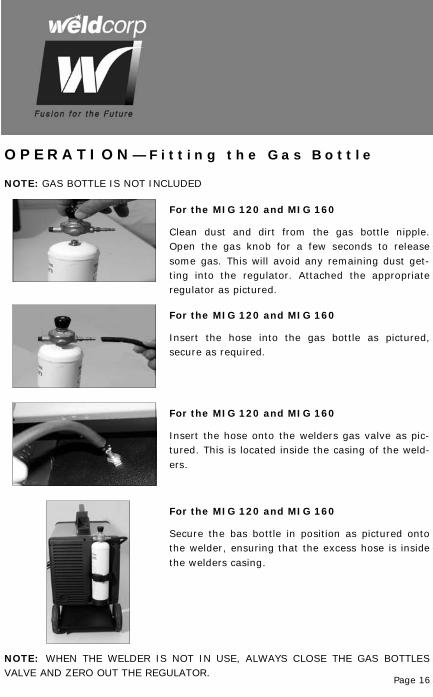
For the MIG 120 and MIG 160
Clean dust and dirt from the gas bottle nipple. Open the gas knob for a few seconds to release some gas. This will avoid any remaining dust get-ting into the regulator. Attached the appropriate regulator as pictured.
For the MIG 120 and MIG 160
Insert the hose into the gas bottle as pictured, secure as required.
For the MIG 120 and MIG 160
Secure the bas bottle in position as pictured onto the welder, ensuring that the excess hose is inside the welders casing.
For the MIG 120 and MIG 160
Insert the hose onto the welders gas valve as pic-tured. This is located inside the casing of the weld-ers.
Page 16
NOTE: WHEN THE WELDER IS NOT IN USE, ALWAYS CLOSE THE GAS BOTTLES VALVE AND ZERO OUT THE REGULATOR.
NOTE: GAS BOTTLE IS NOT INCLUDED
Page 17
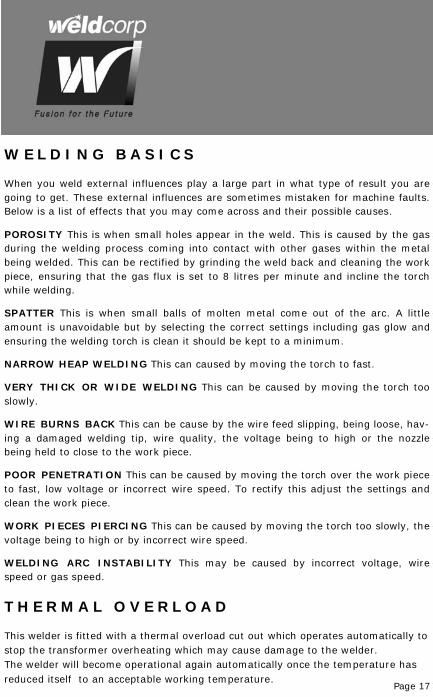
W E L D I N G B A S I C S
When you weld external influences play a large part in what type of result you are going to get. These external influences are sometimes mistaken for machine faults. Below is a list of effects that you may come across and their possible causes. POROSITY This is when small holes appear in the weld. This is caused by the gas during the welding process coming into contact with other gases within the metal being welded. This can be rectified by grinding the weld back and cleaning the work piece, ensuring that the gas flux is set to 8 litres per minute and incline the torch while welding. SPATTER This is when small balls of molten metal come out of the arc. A little amount is unavoidable but by selecting the correct settings including gas glow and ensuring the welding torch is clean it should be kept to a minimum. NARROW HEAP WELDING This can caused by moving the torch to fast. VERY THICK OR WIDE WELDING This can be caused by moving the torch too slowly. WIRE BURNS BACK This can be cause by the wire feed slipping, being loose, hav-ing a damaged welding tip, wire quality, the voltage being to high or the nozzle being held to close to the work piece. POOR PENETRATION This can be caused by moving the torch over the work piece to fast, low voltage or incorrect wire speed. To rectify this adjust the settings and clean the work piece. WORK PIECES PIERCING This can be caused by moving the torch too slowly, the voltage being to high or by incorrect wire speed. WELDING ARC INSTABILITY This may be caused by incorrect voltage, wire speed or gas speed.
T H E R M A L O V E R L O A D
This welder is fitted with a thermal overload cut out which operates automatically to stop the transformer overheating which may cause damage to the welder. The welder will become operational again automatically once the temperature has reduced itself to an acceptable working temperature.
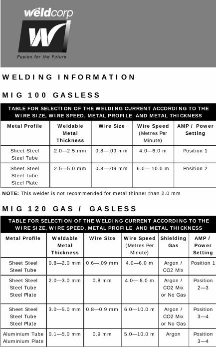
TABLE FOR SELECTION OF THE WELDING CURRENT ACCORDING TO THE WIRE SIZE, WIRE SPEED, METAL PROFILE AND METAL THICKNESS
Metal Profile Weldable Metal
Thickness
Wire Size Wire Speed (Metres Per
Minute)
AMP / Power Setting
Sheet Steel Steel Tube
2.0—2.5 mm 0.8—.09 mm 4.0—6.0 m Position 1
Sheet Steel Steel Tube Steel Plate
2.5—5.0 mm 0.8—.09 mm 6.0— 10.0 m Position 2
NOTE: This welder is not recommended for metal thinner than 2.0 mm
W E L D I N G I N F O R M A T I O N
M I G 1 0 0 G A S L E S S
M I G 1 2 0 G A S / G A S L E S S
TABLE FOR SELECTION OF THE WELDING CURRENT ACCORDING TO THE WIRE SIZE, WIRE SPEED, METAL PROFILE AND METAL THICKNESS
Metal Profile Weldable Metal
Thickness
Wire Size Wire Speed (Metres Per
Minute)
AMP / Power Setting
Sheet Steel Steel Tube
0.8—2.0 mm 0.6—.09 mm 4.0—6.0 m Position 1
Sheet Steel Steel Tube Steel Plate
2.0—3.0 mm 0.8 mm 4.0— 8.0 m Position 2—3
Shielding Gas
Argon / CO2 Mix
Argon / CO2 Mix
or No Gas
Sheet Steel Steel Tube Steel Plate
3.0—5.0 mm 0.8—0.9 mm 6.0—10.0 m Argon / CO2 Mix
or No Gas
Position 3—4
Aluminium Tube Aluminium Plate
0.1—5.0 mm 0.9 mm 5.0—10.0 m Argon Position 3—4
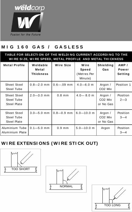
M I G 1 6 0 G A S / G A S L E S S
TABLE FOR SELECTION OF THE WELDING CURRENT ACCORDING TO THE WIRE SIZE, WIRE SPEED, METAL PROFILE AND METAL THICKNESS
Metal Profile Weldable Metal
Thickness
Wire Size Wire Speed
(Metres Per Minute)
AMP / Power Setting
Sheet Steel Steel Tube
0.8—2.0 mm 0.6—.09 mm 4.0—6.0 m Position 1
Sheet Steel Steel Tube Steel Plate
2.0—3.0 mm 0.8 mm 4.0— 8.0 m Position 2—3
Shielding Gas
Argon / CO2 Mix
Argon / CO2 Mix
or No Gas
Sheet Steel Steel Tube Steel Plate
3.0—5.0 mm 0.8—0.9 mm 6.0—10.0 m Argon / CO2 Mix
or No Gas
Position 3—4
Aluminium Tube Aluminium Plate
0.1—5.0 mm 0.9 mm 5.0—10.0 m Argon Position 3—4
WIRE EXTENSIONS (WIRE STICK OUT)
TOO SHORT
NORMAL
TOO LONG
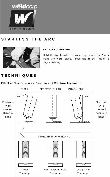
STARTING THE ARC
Hold the torch with the wire approximately 2 mm from the work piece. Press the torch trigger to begin welding.
S T A R T I N G T H E A R C
T E C H N I Q U E S
Effect of Electrode Wire Position and Welding Technique
PUSH PERPENDICULAR DRAG / PULL
10 10
DIRECTION OF WELDING
Electrode wire
directed ahead of
bead
Electrode wire
pointed back into
bead
Push Technique
Gun Perpendicular Technique
Drag / Pull Technique
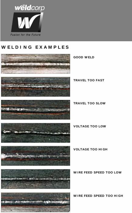
W E L D I N G E X A M P L E S
GOOD WELD
TRAVEL TOO FAST
TRAVEL TOO SLOW
VOLTAGE TOO LOW
VOLTAGE TOO HIGH
WIRE FEED SPEED TOO LOW
WIRE FEED SPEED TOO HIGH
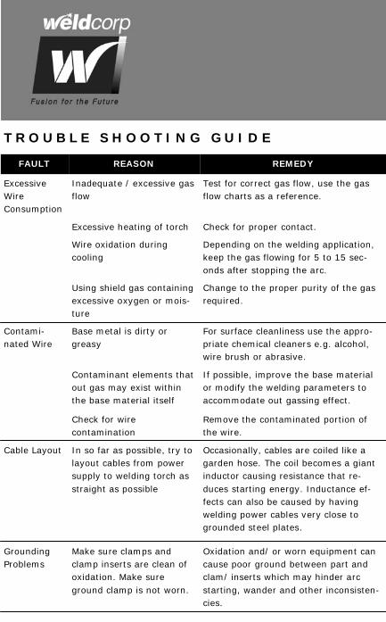
T R O U B L E S H O O T I N G G U I D E
FAULT REASON REMEDY
Excessive Wire Consumption
Inadequate / excessive gas flow
Test for correct gas flow, use the gas flow charts as a reference.
Excessive heating of torch Check for proper contact.
Wire oxidation during cooling
Depending on the welding application, keep the gas flowing for 5 to 15 sec-onds after stopping the arc.
Using shield gas containing excessive oxygen or mois-ture
Change to the proper purity of the gas required.
Contami-nated Wire
Base metal is dirty or greasy
For surface cleanliness use the appro-priate chemical cleaners e.g. alcohol, wire brush or abrasive.
Contaminant elements that out gas may exist within the base material itself
If possible, improve the base material or modify the welding parameters to accommodate out gassing effect.
Check for wire contamination
Remove the contaminated portion of the wire.
Cable Layout In so far as possible, try to layout cables from power supply to welding torch as straight as possible
Occasionally, cables are coiled like a garden hose. The coil becomes a giant inductor causing resistance that re-duces starting energy. Inductance ef-fects can also be caused by having welding power cables very close to grounded steel plates.
Grounding Problems
Make sure clamps and clamp inserts are clean of oxidation. Make sure ground clamp is not worn.
Oxidation and/ or worn equipment can cause poor ground between part and clam/ inserts which may hinder arc starting, wander and other inconsisten-cies.

Page 23
T R O U B L E S H O O T I N G G U I D E
FAULT REASON REMEDY
Overheat Lights Come On
Overheating of unit Allow 3—5 minutes of “cool down” time. Check for short between nozzle and electrode. Check transistors; as this component starts to wear, it begins to draw more current. If condition is not resettable, take welder to repair agent for service.
Difficulty in Arc Starting
Torch assembled incor-rectly
Check condition of wire
Low voltage problem Check for missing or low voltage
Arc Does Not Transfer
Loose, missing cable con-nections
Check tooling for loose or poor ground.
Power supply not recognis-ing start signal
Check all connections.
Extension Cables
Ensure that any extension cables are of adequate capacity
Low quality/ capacity cables will result in voltage drops and hinder starting.
Gas Quality Gas quality / purity must meet the specified stan-dards.
Try a bottle of gas of higher purity grade than normally used and see if the problem persists. Low gas quality or oxides in gas can oxidise part and con-taminate the wire during welding.
NOTE: If you are still having difficulty with your welder, do not hesitate to contact our service team on:
1800 001 1812
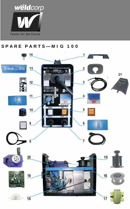
S P A R E P A R T S — M I G 1 0 0
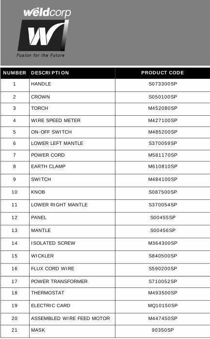
NUMBER DESCRIPTION PRODUCT CODE
1 HANDLE S073300SP
2 CROWN S050100SP
3 TORCH M452080SP
4 WIRE SPEED METER M427100SP
5 ON-OFF SWITCH M485200SP
6 LOWER LEFT MANTLE S370059SP
7 POWER CORD M581170SP
8 EARTH CLAMP M610810SP
9 SWITCH M484100SP
10 KNOB S087500SP
11 LOWER RIGHT MANTLE S370054SP
12 PANEL S00455SP
13 MANTLE S00456SP
14 ISOLATED SCREW M364300SP
15 WICKLER S840500SP
16 FLUX CORD WIRE S590200SP
17 POWER TRANSFORMER S710052SP
18 THERMOSTAT M493500SP
19 ELECTRIC CARD MQ10150SP
20 ASSEMBLED WIRE FEED MOTOR M447450SP
21 MASK 90350SP
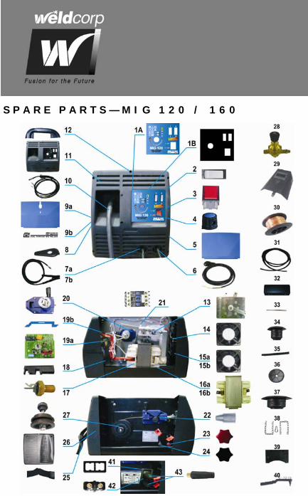
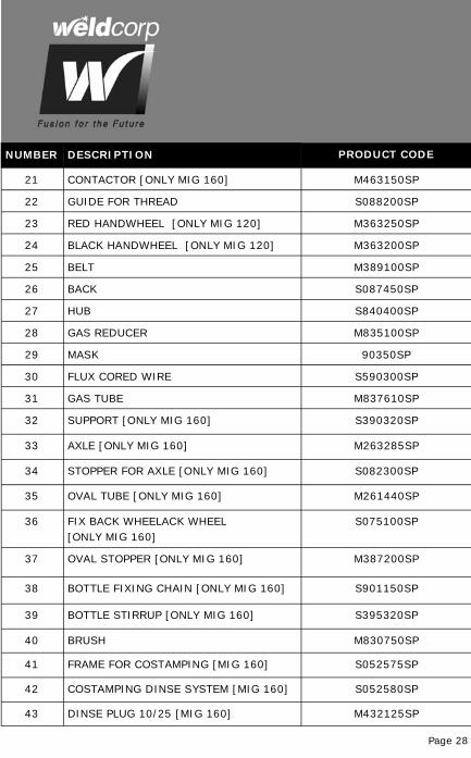
S P A R E P A R T S — M I G 1 2 0 / 1 6 0
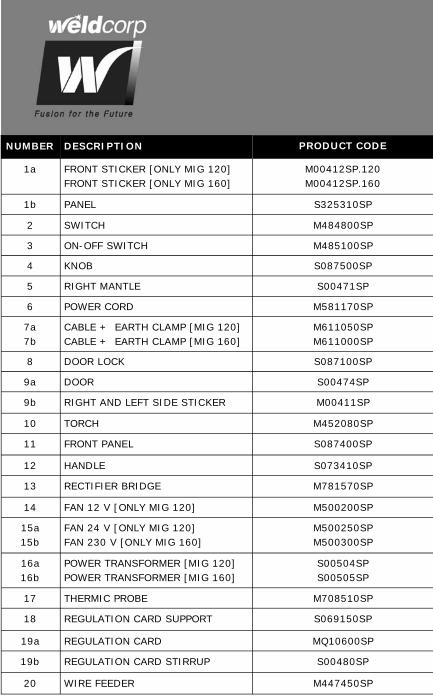
NUMBER DESCRIPTION PRODUCT CODE
1a FRONT STICKER [ONLY MIG 120]FRONT STICKER [ONLY MIG 160]
M00412SP.120 M00412SP.160
1b PANEL S325310SP
2 SWITCH M484800SP
3 ON-OFF SWITCH M485100SP
4 KNOB S087500SP
5 RIGHT MANTLE S00471SP
6 POWER CORD M581170SP
7a 7b
CABLE + EARTH CLAMP [MIG 120] CABLE + EARTH CLAMP [MIG 160]
M611050SP M611000SP
8 DOOR LOCK S087100SP
9a DOOR S00474SP
9b RIGHT AND LEFT SIDE STICKER M00411SP
10 TORCH M452080SP
11 FRONT PANEL S087400SP
12 HANDLE S073410SP
13 RECTIFIER BRIDGE M781570SP
14 FAN 12 V [ONLY MIG 120] M500200SP
15a 15b
FAN 24 V [ONLY MIG 120] FAN 230 V [ONLY MIG 160]
M500250SP M500300SP
16a 16b
POWER TRANSFORMER [MIG 120] POWER TRANSFORMER [MIG 160]
S00504SP S00505SP
17 THERMIC PROBE M708510SP
18 REGULATION CARD SUPPORT S069150SP
19a REGULATION CARD MQ10600SP
19b REGULATION CARD STIRRUP S00480SP
20 WIRE FEEDER M447450SP
Page 28
NUMBER DESCRIPTION PRODUCT CODE
22 GUIDE FOR THREAD S088200SP
23 RED HANDWHEEL [ONLY MIG 120] M363250SP
24 BLACK HANDWHEEL [ONLY MIG 120] M363200SP
25 BELT M389100SP
26 BACK S087450SP
27 HUB S840400SP
28 GAS REDUCER M835100SP
29 MASK 90350SP
30 FLUX CORED WIRE S590300SP
31 GAS TUBE M837610SP
32 SUPPORT [ONLY MIG 160] S390320SP
33 AXLE [ONLY MIG 160] M263285SP
34 STOPPER FOR AXLE [ONLY MIG 160] S082300SP
35 OVAL TUBE [ONLY MIG 160] M261440SP
36 FIX BACK WHEELACK WHEEL [ONLY MIG 160]
S075100SP
37 OVAL STOPPER [ONLY MIG 160] M387200SP
38 BOTTLE FIXING CHAIN [ONLY MIG 160] S901150SP
39 BOTTLE STIRRUP [ONLY MIG 160] S395320SP
40 BRUSH M830750SP
41 FRAME FOR COSTAMPING [MIG 160] S052575SP
42 COSTAMPING DINSE SYSTEM [MIG 160] S052580SP
43 DINSE PLUG 10/25 [MIG 160] M432125SP
21 CONTACTOR [ONLY MIG 160] M463150SP

Page 29
N O T E S
______________________________________________________________ ______________________________________________________________ ______________________________________________________________ ______________________________________________________________ ______________________________________________________________ ______________________________________________________________ ______________________________________________________________ ______________________________________________________________ ______________________________________________________________ ______________________________________________________________ ______________________________________________________________ ______________________________________________________________ ______________________________________________________________ ______________________________________________________________ ______________________________________________________________
Subject to the warranty conditions below, this Weldcorp product (hereinafter called “the product”) is warranted by Weldcorp (thereinafter called “the com-pany”) to be free from defects in material or workmanship for a period of 12 months from the date of original purchase covering both parts and labour. Under the terms of this warranty.
The repair or replacement of any part shall be the opinion of the Company or its authorised agent. Should service become necessary during the warranty period, the owner should contact the Authorised Weldcorp Retailer from whom the Product was purchased. In order to obtain warranty service, the owner must present the sales docket and Warranty Certificate to confirm the date of purchase. This product is sold by the dealer or agent as to give any additional warranty or guarantee on the Company’s behalf except as herein contained or herein referred to. WARRANTY CONDITIONS
This warranty only applies provided that the Product has been used in accor-dance with the manufacture’s recommendations under normal use and reason-able care (in the opinion of the Company) and such warranty does not cover damage, malfunction or failure resulting from misuse, neglect, abuse or used for a purpose for which it was not-designed or is not suited and no repairs, alterations of modifications have been attempted by other than an Authorised Service Agent. This guarantee will not apply if the tool is damaged by accident or if repairs arise from normal wear and tear.
Certain legislation including the Trade Practices Act, 1974 (as amended) and other state and territorial laws give rights to the buyer and impose liability on the seller in certain circumstances. Nothing herein shall have the effect of ex-cluding, restricting or modifying any condition, warranty, right or liability im-posed, to the extent only that such exclusion, restriction or modification would render any term herein void.
Page 30
W A R R A N T Y

Page 31
THIS WARRANTY FORM SHOULD BE REAINED BY THE CUSTOMER AT ALL TIMES
For your record and to assist in establishing date of purchase (necessary for in-warranty service) please keep your purchase docket and this form completed with the following particulars.
PURCHASED FROM _________________________________________________
SUBURB _________________________________________________
DATE _________________________________________________
MODEL NO _________________________________________________
SERIAL NO _________________________________________________
Present this form with your Purchase Docket when WARRANTY service is required.
CALL 1800 001 1812
W A R R A N T Y F O R M

M a n u f a c t u r e d i n I t a l y F H P r a g e r
A D i v i s i o n o f I T W R e t a i l G r o u p P t y L t d .
A B N 9 5 0 0 0 0 4 3 8 7 2
73C ELIZABETH STREET WETHERILL PARK NSW 2164
Free Call: 1800 001 1812
www.weldcorp.net