owner’s mountain bike manual
TRANSCRIPT

THIS MANUAL CONTAINS IMPORTANT SAFETY, PERFORMANCE AND MAINTENANCE INFORMATION. READ THE MANUAL BEFORE TAKING YOUR FIRST RIDE ON YOUR NEW BICYCLE, AND KEEP THE MANUAL HANDY OF FUTURE REFERENCE.
NOTE: Illustrations in this Manual are for reference purposes only and may not reflect the exact appearance of the actual product. Specifications are subject to change without notice.
DO NOT RETURN THIS ITEM TO THE STORE CONTACT DYNACRAFT CUSTOMER SERVICE FOR ASSISTANCE
dynacraftwheels.com/contactor 1-800-551-0032 9 AM – 5 PM ET
MOUNTAIN BIKEOWNER’S MANUAL

2
HELMET USE & GENERAL MANUAL DISCLAIMER
NOTE: The illustrations in this manual are used simply to provide examples; the components of your bicycle might differ. In addition, some of the parts shown might be optional and not part your bicycle’s standard equipment.
The following manual is only a guide to assist you and is not a complete or comprehensive manual of all aspects of maintaining and repairing your bicycle. If you are not comfortable, or lack the skills or tools to assemble the bicycle yourself, you should take it to a qualified mechanic at a bicycle shop. Additionally, you can write or call us concerning missing parts or assembly questions.
WARNING/IMPORTANT: Take notice of this symbol throughout this manual and pay particular attention to the instructions blocked off and preceded by this symbol.
Dynacraft BSC, Inc.1501 Crossgate RoadPort Wentworth, GA 31407Call Toll Free 1-800-551-0032Monday – Friday 9AM to 5PM ESTdynacraftwheels.com©2020 All rights reserved

3
Correct fittingMake sure your helmet covers your forehead.
Incorrect fittingForehead is exposed and vulnerable to serious injury.
HELMETS SAVE LIVES! WARNING: Always wear a properly fitted helmet when you ride your bicycle.
Do not ride at night. Avoid riding in wet conditions.

4
ABOUT THIS MANUALThis manual was written to help you get the most performance, comfort, enjoyment and safety when riding your new bicycle. It is important for you to understand your new bike. By reading this manual before you go out on your first ride, you’ll know how to get the most from your new bicycle. It is also important that your first ride on your new bicycle is taken in a controlled environment, away from cars, obstacles, and other cyclists.
GENERAL WARNINGBicycle riding can be a hazardous activity even under the best of circumstances. Proper maintenance of your bicycle is your responsibility as it helps reduce the risk of injury. This manual contains many “WARNINGS” and “CAUTIONS” concerning the consequences of failure to maintain or inspect your bicycle. Many of the warnings and cautions say, “you may lose control and fall.” Because any fall can result in serious injury or even death, we do not repeat the warning of possible injury or death whenever the risk of falling is mentioned. Dynacraft does not encourage stunting, trick riding, ramp riding, jumping, aggressive riding, riding on severe terrain, riding in severe climates, riding with heavy loads, riding double, commercial activities; such use is inherently dangerous, can cause serious injury to the rider, and if done it is with the rider’s express and implied assumption of the risk of such use and Dynacraft shall not have any responsibility for any breakdown of the bicycle, its components or rider injuries that occur during such use.
NOTE TO PARENTSIt is a tragic fact that most bicycle accidents involve children. As a parent or guardian, you bear the responsibility for the activities and safety of your minor child. Among these responsibilities are to make sure that the bicycle that your child is riding is properly fitted to the child; that it is in good repair and safe operating condition; that the play of young children is supervised by an adult; that you and your child have learned, understand and obey not only the applicable local motor vehicle, bicycle and traffic laws, but also the common sense rules of safe and responsible bicycling. As a parent, you should read this manual before letting your child ride the bicycle. Please make sure that your child always wears an approved bicycle helmet when riding.

5
CONTENTS
A ABOUT YOUR BIKE . . . . . . . . . . . . . . . . . . . . . . . . . . . . . . . . 7Model/Serial Number Identification 7Customer Service 7Spaces to Write Info 7
B BEFORE YOU RIDE . . . . . . . . . . . . . . . . . . . . . . . . . . . . . . . . 8Parts List 8Tool List 9Frame Sizing 10Rules of the Road/Safety Tips 11Night Riding 13Safety Checklist 14
C BICYCLE ASSEMBLY . . . . . . . . . . . . . . . . . . . . . . . . . . . . . . 16Getting Started 16 1 Pedals 17 2 Seat 18 3 Testing Seat Clamp and Post Clamp Tightness 19 4 Handlebar/Stem 20 5 Testing Handlebar and Stem Tightness 23 6 Front Wheel 24 7 Brakes 25 8 Testing Brake Functions 27 9 Dual Suspension 28 10 Tire inflation 30 11 Reflectors 31 12 Accessories 32

6
D BICYCLE ADJUSTMENTS . . . . . . . . . . . . . . . . . . . . . . . . . . . . 33Seat Adjustment 33Stem Adjustment 34Handlebar Adjustment 35Brake Adjustment 36Shifter Adjustment 38Derailleur Adjustment 39
E MAINTENANCE AND INSPECTION . . . . . . . . . . . . . . . . . . . . . . . 40Tire Removal/Seating 41Lubrication 42Bearing Inspection 43
F LIMITED WARRANTY . . . . . . . . . . . . . . . . . . . . . . . . . . . . . . 44
7
ABOUT YOUR BIKE
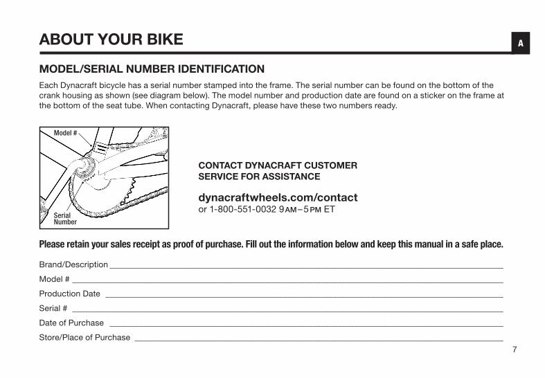
MODEL/SERIAL NUMBER IDENTIFICATIONEach Dynacraft bicycle has a serial number stamped into the frame. The serial number can be found on the bottom of the crank housing as shown (see diagram below). The model number and production date are found on a sticker on the frame at the bottom of the seat tube. When contacting Dynacraft, please have these two numbers ready.
Please retain your sales receipt as proof of purchase. Fill out the information below and keep this manual in a safe place.
Brand/Description _______________________________________________________________________________________________
Model # ________________________________________________________________________________________________________
Production Date ________________________________________________________________________________________________
Serial # ________________________________________________________________________________________________________
Date of Purchase _______________________________________________________________________________________________
Store/Place of Purchase _________________________________________________________________________________________
CONTACT DYNACRAFT CUSTOMER SERVICE FOR ASSISTANCE
dynacraftwheels.com/contact or 1-800-551-0032 9 AM – 5 PM ET
Serial Number
Model #
A

8
BEFORE YOU RIDEB
21
31
32
17
18
3
6
10
7
2
16
29
27
4
8
5 28
12
13
11
15
14
30
20
19
25
22
26
1
9
24
23
9
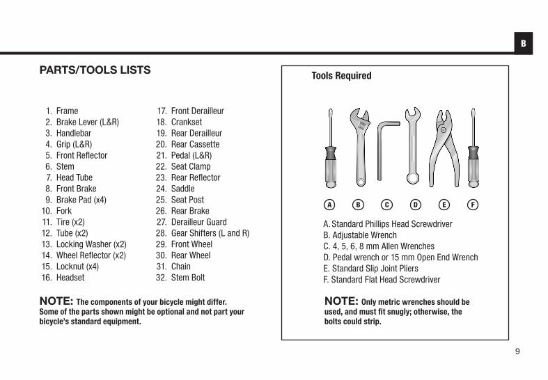
PARTS/TOOLS LISTS
A Standard Phillips Head ScrewdriverB Adjustable WrenchC 4, 5, 6, 8 mm Allen WrenchesD Pedal wrench or 15 mm Open End WrenchE Standard Slip Joint PliersF Standard Flat Head Screwdriver
1 Frame 2 Brake Lever (L&R) 3 Handlebar 4 Grip (L&R) 5 Front Reflector 6 Stem 7 Head Tube 8 Front Brake 9 Brake Pad (x4) 10 Fork 11 Tire (x2) 12 Tube (x2) 13 Locking Washer (x2) 14 Wheel Reflector (x2) 15 Locknut (x4) 16 Headset
17 Front Derailleur 18 Crankset 19 Rear Derailleur 20 Rear Cassette 21 Pedal (L&R) 22 Seat Clamp 23 Rear Reflector 24 Saddle 25 Seat Post 26 Rear Brake 27 Derailleur Guard 28 Gear Shifters (L and R) 29 Front Wheel 30 Rear Wheel 31 Chain 32 Stem Bolt
B
A B C D E F
Tools Required
NOTE: Only metric wrenches should be used, and must fit snugly; otherwise, the bolts could strip.
NOTE: The components of your bicycle might differ. Some of the parts shown might be optional and not part your bicycle’s standard equipment.

10
FRAME SIZINGWhen selecting a new bicycle, the correct choice of frame size is a very important safety consideration. To determine the correct size bicycle for the rider:
• Straddle the assembled bicycle with feet shoulder width apart and flat on the ground.
• There must be at least one inch (2.5 cm) of clearance between the highest part of the top tube of the bicycle and the crotch of the rider with the tires properly inflated.
• The standover height for each bike is listed in the information center on the product page of every bike on dynacraftwheels.com
• To measure the inseam, use measuring tape to measure from the ground (with shoes on) to the inseam of your pants.
• Subtract the standover height from the inseam measurement to ensure that you have the recommended amount of clearance. If you have less than one inch or more than three inches (2.5 to 7.5 cm), you may need to move up or down a frame size.
• For more detailed instructions on how to properly adjust your bike to fit you, visit our website at dynacraftwheels.com, find your bike, and locate the fit video in the Information Center. (Disclaimer: Fit video not available for all products)
WEIGHT LIMITThe maximum structural weight recommendations for our bicycles that are 20 inches or larger are:
• 20 inch bicycles: 176 lb (80 kg)• Adult bicycles up to 29 inches: 275 lb (125 kg)
CAUTION: For safe and comfortable riding there should be a clearance of no less than 1 inch between the inseam area of the intended rider and the top tube of the bicycle frame, while the rider straddles the bicycle with both feet flat on the ground.
WARNING: If the bicycle is too large the rider cannot reach the pedals easily, or the ground when stopping which may result in loss of control and/or injury.
B

11
RULES OF THE ROAD/SAFETY TIPS
NOTE: Like any sport, bicycling involves risk of injury and damage. By choosing to ride a bicycle, you assume the responsibility for that risk; not the people who sold you the bike; nor the people who made it; nor the people who distribute it; nor the people who manage or maintain the roads and trails you ride on. YOU. So you need to know – and to practice – the rules of safe and responsible riding.
1. IN THE INTEREST OF SAFER CYCLING, MAKE SURE YOU READ AND UNDERSTAND YOUR OWNER’S MANUAL. NOTE AND PERFORM PRE-RIDE SAFETY CHECKS.
2. NOTICE: Some state and local laws may require that your bicycle be equipped with a warning device such as a horn or bell and a front and rear light if the bicycle is to be ridden after dark.
3. ALWAYS WEAR SHOES when riding a bicycle and AVOID LOOSE FITTING CLOTHES.
4. CHECK YOUR BRAKES FREQUENTLY. THE ABILITY TO STOP YOUR BICYCLE IS CRITICAL. Roads are slippery when wet so avoid sharp turns and allow more distance stopping. Caliper brakes may become less efficient when wet. Leaves, loose gravel, and other debris can also affect stopping.
5. ALWAYS RIDE IN THE SAME DIRECTION AS TRAFFIC. Never ride against traffic.
6. STOP AND LOOK BEFORE YOU LEAVE AN ALLEY, DRIVEWAY, OR PARKING LOT. Stop, look to the left, to the right, and to the left again for traffic. Ride only when it is clear.
7. KEEP TO THE RIGHT. Follow the traffic flow in a straight line and stay close to the curb or in the bike lane, when available. Watch for cars moving in and out of traffic.
8. OBEY ALL TRAFFIC LAWS REGULATIONS. Most traffic regulations apply to bike riders as well as automobile operators.
9. ONE RIDER PER BIKE. NEVER CARRY OTHER RIDERS. This is dangerous and makes the bike harder to control. The bicycles distributed by Dynacraft BSC, Inc. are intended for one rider only.
B
12
10. ALWAYS BE ALERT. BE ALERT – pedestrians have the right of way. BE ALERT – when riding near parked cars - ride far enough away from the cars so that you won’t get hit if someone opens the car door.
11. USE CAUTION AT ALL INTERSECTIONS AND STOP SIGNS. STOP AND LOOK BOTH WAYS BEFORE PROCEEDING.
12. USE HAND SIGNALS. Communicate by using hand signals to tell other drivers what you are going to do. Signal 100 feet before turning unless your hand is needed to control the bike.
13. PROPER LIGHTS ARE RECOMMENDED IF YOU RIDE AT NIGHT. Be sure to have a strong head-light, a tail light, and a full set of reflectors. CHECK THAT REFLECTORS ARE CLEAN, STRAIGHT, UNBROKEN, AND SECURELY MOUNTED.
14. NEVER CARRY PACKAGES OR OBJECTS WHICH OBSTRUCT VISION.
15. NEVER HITCH RIDES, never hold onto a moving vehicle while riding.
16. THE KICKSTAND IS DESIGNED TO SUPPORT THE BICYCLE ONLY, not the bicycle and the rider.
17. AVOID THE FOLLOWING HAZARDS: Drain grates, potholes, soft road edges, gravel, sand, wet leaves, and/or any obstruction in the road. Failure to do so could cause wheel(s) to buckle and result in personal injury to the rider.
18. WET WEATHER RIDING - Riding your bicycle in wet conditions is not recommended. In wet conditions traction and braking power is reduced. Riding in such conditions could result in personal injury.
19. PROPER HELMET USE. A helmet that meets the CPSC (Consumer Product Safety Commission) standard should always be worn when riding a bicycle. The helmet should fit properly and be worn on the crown of the head, not tipped back. Ensure to replace your helmet at least every three years to ensure the structural integrity of the foam. Replace after impact, regardless of lack of visible damage to helmet.
20. USE BIKE LANES when available. Also note that in certain states, cars may use bike lanes when turning.
21. RESPECT “Bicycles Are Prohibited” SIGNS.
B

13
NIGHT RIDINGRiding a bicycle at night is much more dangerous than riding during the day. A bicyclist is very difficult for motorists and pedestrians to see. Therefore, children should never ride at dawn, dusk or at night. Adults who choose to accept the greatly increased risk of riding at dawn, dusk or at night need to take extra care both riding and choosing specialized equipment which helps reduce that risk. Consult your dealer about night riding safety equipment.
WARNING: Reflectors are not a substitute for required lights. Riding at dawn, at dusk, at night or at other times of poor visibility without an adequate bicycle lighting system and without reflectors is dangerous and may result in serious injury or death.
WARNING: Do not remove the front or rear reflectors or reflector brackets from your bicycle. They are an integral part of the bicycle’s safety system. Removing the reflectors reduces your visibility to others using the roadway. Being struck by other vehicles may result in serious injury or death.
RULES FOR CHILDRENTo avoid an accident, teach children good riding skills with an emphasis on safety from an early age.
1. Always wear a properly fitted helmet. 2. Do not play in driveways or the road. 3. Do not ride on busy streets.4. Do not ride at night.5. Obey all traffic laws, especially stop signs and red lights.6. Be aware of other road vehicles behind and nearby. 7. Before entering a street: Stop, look left, right, and left again for traffic.8. If riding downhill, be extra careful. Slow down using the brakes and maintain control of steering.9. Never take your hands off the handlebars, or your feet off the pedals when riding downhill.
CAUTION: The Consumer Product Safety Commission advises that the riding of small wheel diameter bicycles at excessive speeds can lead to instability and is not recommended.
B

14
SAFETY CHECKLISTBefore every ride, it is important to carry out the following safety checks: (For information and instructions on performing specific equipment checks, locate the relevant section in the manual referenced on pages 5–6.)
1. BRAKES• Ensure front and rear brakes work properly.• Ensure brake pads are not over worn and are correctly positioned in relation to the rims. • Ensure brake control cables are properly lubricated, correctly adjusted, and display no obvious wear. • Ensure brake control levers are properly lubricated and tightly secured to the handlebar.
2. DERAILLEURS
• Check that the front and rear derailleurs are adjusted and functioning properly.• Ensure that the shifter levers are securely attached.• Ensure that derailleurs, shift levers, and control cables are properly lubricated.• Shift through all the gears while pedaling to ensure that the derailleurs are adjusted and functioning
properly.
3. CRANKS AND PEDALS• Ensure pedals are securely tightened to the cranks.• Ensure cranks are securely tightened to the bottom bracket and are not bent.
4. FRAME AND FORK• Check that the frame and fork are not bent, broken, or cracked.• If either are found to be bent, broken, or cracked, they should be replaced.
B

15
5. WHEELS AND TIRES
• Ensure tires are inflated to within the recommended range as displayed on the tire sidewall.• Ensure tires have tread and have no bulges or excessive wear.• Ensure rims run true and have no obvious wobbles or kinks.• Ensure all wheel spokes are tight and not broken.• Check that axle nuts are tight.• Do not over inflate.
6. CHAIN
• Ensure chain is oiled, clean and runs smoothly.• Extra care is required in wet or dusty conditions.• On bicycles equipped with coaster brakes, check for proper chain tension.• Check to make sure your chain guard is tight and not touching the crank or chain.
7. BEARINGS• Ensure all bearings are lubricated, run freely and display no excess movement, grinding or rattling.• Check headset, wheel bearings, pedal bearings and bottom bracket bearings.
8. STEERING• Ensure handlebar and stem are correctly adjusted and tightened, and allow proper steering.• Ensure that the handlebars are set correctly in relation to the forks and the direction of travel.
B

16
BICYCLE ASSEMBLY
GETTING STARTEDOpen the box and check that all parts are present. You can check against the list on page 9, but note that the components of your bicycle might differ. If you experience a problem with this product, or are missing a part, please contact our Customer Service Team at dynacraftwheels.com/contact, rather than return this product to the store.
We strongly recommend reading the manual before beginning. If you aren’t comfortable with the assembly, you should bring your new ride to your local bike shop to have a qualified mechanic put it together for you. In any event, you need to read this entire Owner’s Manual before you ride or let anyone else ride it.
CAUTION: As you assemble the bike, it’s a good idea to place a little white lithium grease or anti-seize compound on the seatpost, stem and threads of the bolts to prevent rusting.
You’ll see that the frame, handlebars, front wheel, and other components are attached with zip ties. Lift everything out in one piece, and set it down, with the chain facing upwards. Cut the zip ties, and remove any padding or packaging.
First, align the fork. Rotate it, to ensure it moves freely without binding (see Figure 1), making sure the fork is pointing in the right direction, with the fork blades facing forward (see Figure 2).
Figure 1
Figure 2
C

17
1. PEDALS
WARNING: Attachment of an incorrect pedal into a crank arm will cause irreparable damage. Unless the shoulder of the pedal spindle is tight to the face of the crank arm, the pedal may back out causing serious injury or death. Make it tight so the shoulder is in complete contact with the surface of the crank arm.
Before your first ride, please check to ensure your pedals are attached correctly.
• There is a right side pedal marked “R” and a left side pedal marked “L”• The right pedal has a RED sticker, the Left pedal has a GREEN sticker.• Pedal marked “R” has right hand threads. Tighten in a clockwise direction.• Pedal marked “L” has left hand threads. Tighten in a counterclockwise
direction (see Figure 3).After putting some white lithium grease on the threads of the pedal, place the pedal into the crank, and use your fingers to get it started. Threading it in can be tricky, so make sure to do it correctly. Regardless of which side you’re working on, the top of the thread will rotate towards the front of the bike to tighten the pedals. Once you’ve finger tightened the pedals, use a 15 mm open-ended wrench to snug them down. They are properly tightened when the pedal spindle, which is the axle that the pedal platform spins around, begins to bite into the metal on the crank.
If you have a three piece crank, check the crank bolts to make sure they are tightened (see Figure 4). Re-check the bolts after your first ride.
If you have a one piece crank, firmly grasp the crank arm on the left side of the bicycle and wiggle it gently. If there is any movement or play in the crank, use a 15 mm open-ended wrench to tighten the locknut. Repeat the process until there is no more play in the crank, being careful not to overtighten (see Figure 5).
WARNING: Never ride your bike if the cranks are loose. This could damage the crank arms beyond repair, and result in a loss of control, injury or death.
Figure 3
Figure 4 Figure 5
C
Counterclockwise
Clockwise

18
2. SEAT
WARNING: The seatpost must be inserted far enough so that the minimum insertion marks cannot be seen.
Add some white lithium grease to the inside of the seat tube, and slide the seatpost into the bicycle. Make sure that the minimum insertion mark is completely covered and that the seat is pointing forward in alignment with the bicycle (see Figures 6 and 7).
CAUTION: Operate the quick release lever by hand only. Do not use a hammer or any other tool to tighten the quick release lever.
WARNING: If the quick release lever is not tightened properly, the seatpost can loosen while riding. This can cause a loss of control and injury to the rider or others.
To install the seat post reflector, first remove the seatpost and saddle from the bike. Use (A) Standard Phillips Head Screwdriver to loosen the screw on the clamp of the reflector until you can slide the reflector over the seat post. Once the reflector is on the seat post, reinsert the seat post back into the seat tube. Position the reflector so that it is perpendicular to the ground, and move it up on the seat post until it can be seen above the tire when viewing the bike from the rear (see Figure 8).
Minimum insertion marks are located on the seatpost
Seat tube
Seatpost
Figure 6
Figure 7
Figure 8
C

19
If your bike has a quick release lever (see Figure 9), tighten it by holding the lever in the “open” position and tightening the nut on the opposite side by hand. Slowly close the quick release lever, and you should notice resistance when the lever is half way shut. Firmly continue to push the lever until it is in the “closed” position, and the word “close” is showing. The seat should not be able to move back and forth, up and down, or side to side with the quick release lever in the closed position. Make sure the lever is also parallel with the seat clamp itself. You should only need one hand to close the quick release lever. If you need two hands, the seat clamp is too tight. Loosen the nut on the clamp until only one hand is needed to close the seat clamp.
If your bike has a standard seat clamp (see Figure 10), use (B) an Adjustable Wrench(es) to tighten the nut securely. If your bike has a bolt on seat clamp (see Figure 11), use (C) a 4, 5, or 6 mm Allen Wrench to tighten the bolt securely. The seat should not be able to move back and forth, up and down, or side to side with the seat clamp tightened.
3. TESTING SEAT CLAMP AND POST CLAMP TIGHTNESSAfter installing the seatpost into the bicycle and tightening the clamp, test the tightness of the saddle. Hold the saddle firmly with both hands and try to move it side to side. The seatpost should not move at all. The seatpost and saddle also should not move when the rider is seated. Make sure the seat clamp nuts at the top of the seatpost are tight so that the seat does not tip forward or backwards (see Figures 12 & 13).
Open
Closed
Figure 10
Figure 9
Figure 11
Figure 12 Figure 13
C

20
Minimum insertion mark
Figure 14
C
4. HANDLEBAR/STEM
WARNING: To prevent steering system damage and possible loss of control, the stem must be inserted enough so that the minimum insertion marks are completely covered (see Figure 14).
Add some white lithium grease to the inside of the fork steerer tube. Before installing the stem, ensure that you have all the parts present and installed in the correct order (see Figure 17). For a threaded or quill stem, remove the plastic shipping cap from the bottom of the stem (see Figure 15).
Insert the stem and handlebar assembly into the fork, making sure the stem wedge is loose (see Figure 16). Make sure the cables are not tangled and track smoothly on either side of the stem.
Remove cap
Figure 15 Figure 16 Figure 17
Fork Cone Locknut
Fork Cone
WasherAdjustable CupBall Retainer
Ball Retainer
Bearing Cup
Bearing Cup

21
C
The stem should be pointing towards the front of the bike, aligned with the front tire (see Figure 18). Depending on the type of bolt, tighten the stem bolt with either (B) an adjustable wrench or (C) a 4, 5, or 6 mm Allen wrench (see Figure 19).
If your bicycle comes with a threadless stem (see Figure 20), we must first remove the headset in order to install. Use (C) a 4, 5, or 6 mm Allen wrench to remove the pre-load bolt, cap and cardboard spacer from the headset. Discard the cardboard spacer (see Figure 22).
Loosen the bolts on the side of the stem, slide the stem into place, making sure it lines up with the fork (see Figure 18). Check the gap between the steerer tube and stem, ensuring there is enough space to reinstall the cap and bolt. (See Figure 21) If you need it higher or lower, your local bike mechanic can help you out with the adjustment. Snug the pre-load bolt on top. Then tighten the two bolts on the side of the stem, alternating each bolt.
Figure 20 Figure 21
Figure 18
Figure 19 Figure 22
Pre-Load Bolt
Top Cap
Stem
Spacer
Bearing
Spacer
Cup

22
C
The handlebars should come attached to the stem. Simply ensure that the brake and derailleur cables track smoothly, and that the handlebar bolt(s) are properly tightened with (C) a 4, 5, or 6 mm Allen Wrench. (See Figures 23-25). In the case of a 2 or 4-bolt stem, tighten the bolts alternating between bolts every few turns. We will adjust the position and rotation of the handlebars, brake levers, and shifters later on (see page 35).
Figure 23
Figure 24 Figure 25

23
5. TESTING HANDLEBAR AND STEM TIGHTNESSTo test the tightness of the stem, straddle the front wheel between your legs tightly (see Figures 26 & 27). Try to turn the handlebar back and forth. The handlebar should not slip or move independently of the front wheel at all. If the handlebar does move, re-align the stem with the front wheel and tighten the stem bolt. Re-test to make sure the stem is secure with the same process.
To test the tightness of the handlebar, hold the bike stationary and try to rotate the ends of the handlebar up and down or move the bar forward and back. If the handlebar moves, loosen the handlebar clamp nut or bolts evenly to re-position and then re-tighten. Repeat the test until the bars will not move.
WARNING: To prevent steering system damage and possible loss of control, the stem and handlebars must be properly adjusted and tightened. DO NOT OVERTIGHTEN.
C
Figure 26
Figure 27

24
6. FRONT WHEELBefore installing the front wheel, ensure that the brakes are opened enough to allow the tire to fit through them. On side-pull equipped bikes, you may have to loosen the cable anchor bolt (see Figure 31) in order to allow the tire to fit through. On Linear Brake equipped bikes, squeeze the brake arms together by hand, and lift the cable out of the carrier to open up the brakes (see Figure 33).
To install the front wheel, insert the wheel in the dropouts, place the locking washer on the axle, line up the tab on the retainer clip with the corresponding hole in the drop out. Place the locknut on the axle after the retainer clip and tighten the lock nut with (B) Adjustable Wrench (see Figures 28 & 29).
WARNING: Put the wheel in the center of the fork and tighten both nuts.
WARNING: Failure to obey these steps can allow the front wheel to loosen or dislodge while riding. This can cause injury or death to the rider or to others.
C
Retainer Clip
Locknut
Drop-out
Figure 28
Figure 29

25
C
7. BRAKES
WARNING: When assembling or adjusting the brakes, make sure the cable anchor nut is tight. Failure to securely tighten the nut could result in brake failure and personal injury (see Figure 31).
7A. Side Pull BrakesAfter installing the front wheel, loosen the cable anchor nut and pull the brake cable through it. Squeeze the brake arms together against the rim of the wheel. While still holding the brake arms, pull the cable firmly through the cable anchor nut and tighten the nut securely (see Figures 30 & 31). To fine tune your brakes, see the adjustment section on pages 35-37.
7B. Linear Pull BrakesAfter installing the front wheel, re-connect the front brake by squeezing the arms together, and sliding the cable guide back into the carrier (see Figures 32 & 33).
Brake CableCable Carrier
Brake cable
Brake arm
Brake arm
Cable Anchor Bolt
Brake pad
Brake pad
Cable Anchor Nut
Figure 32 Figure 33
Figure 31Figure 30

26
7C. Disc BrakesWhen installed properly, the disc brake rotor should be centered between the brake pads, and securely fastened to the wheel (see Figure 34). Use (C) a 4, 5, or 6 mm Allen Wrench to check the rotor mounting bolts to ensure that none of the bolts are loose. To tighten the brake cable, loosen the cable anchor bolt, pull the cable taught, and re-tighten the bolt (see Figure 35).
Ensure that the mounting bolts on Disc Brake are evenly tightened (see Figure 35). If not, the Disc Brakes will be out of alignment with the Rotor, and you will not be able to brake efficiently or safely.
NOTE: If your bike is equipped with a disc brake, make sure that the disc rotor slides easily into the brake caliper when installing the front wheel. DO NOT pull on the lever before the wheel is installed. It may cause the brake pads to bind together and it is difficult to separate them without the proper tools and expertise.
Figure 35
C
Figure 34

27
8. TESTING BRAKE FUNCTIONSAs part of the initial assembly, you will need to check test the brake function and adjust the brakes as necessary to make sure they are functioning properly. For detailed instructions on brake adjustments, please see pages 35–37.
To test the function of the front hand brake, lift the front of the bike and spin the wheel. The wheel should not rub on the brake pads. Next, squeeze the brake lever and take note of the brake pads contacting the side of the wheel. The pads should contact the rim on both sides at the same time. Finally, hold the brake lever firm and try to move the bike forward. The brake should hold well enough to keep the wheel from moving. Repeat these steps for the rear wheel (see Figure 36).
C
Rear brakeFront brake
Figure 37
Figure 36

28
9. DUAL SUSPENSIONDual suspension bikes are equipped with a front fork as well as a rear suspension generally located below the seat (see Figure 38). The rear suspension unit is a combination of a piston that works in conjunction with a spring to allow the rear swing arm to rotate on a pivot point. Ensure all attaching hardware is secured and there is no lateral movement of the rear triangle (see Figure 39). The amount of Rear Suspension travel can be adjusted by turning the adjusting plate. Clockwise will increase spring tension and decrease travel, while turning counterclockwise will decrease spring tension and increase travel. There are many different types of suspension systems, too many to deal with individually in this manual.
WARNING: There must be enough tension on the spring to hold the spring plate in place. Failure to do this may cause the mechanism to fail. Failure to maintain, check and properly adjust the suspension system may result in suspension malfunction, which can cause you to lose control and fall. Changing suspension adjustment can change the handling and braking characteristics of your bicycle. Always check for changes in the performance of your bicycle by taking a careful test ride in a hazard free area. If your bike has suspension equipment, the increased speed you may develop also increases your risk. When braking, the front of a suspended bike dips. You could lose control and fall if your skill is not up to handling this system. Get to know how to handle your suspension system safely before trying any downhill or very fast biking.
Figure 38
Figure 39
C
Rear Suspension
Front Fork
Anchor Bolt
Spring Plate
Spring
Anchor Bolt
Adjusting Plate
Piston
29
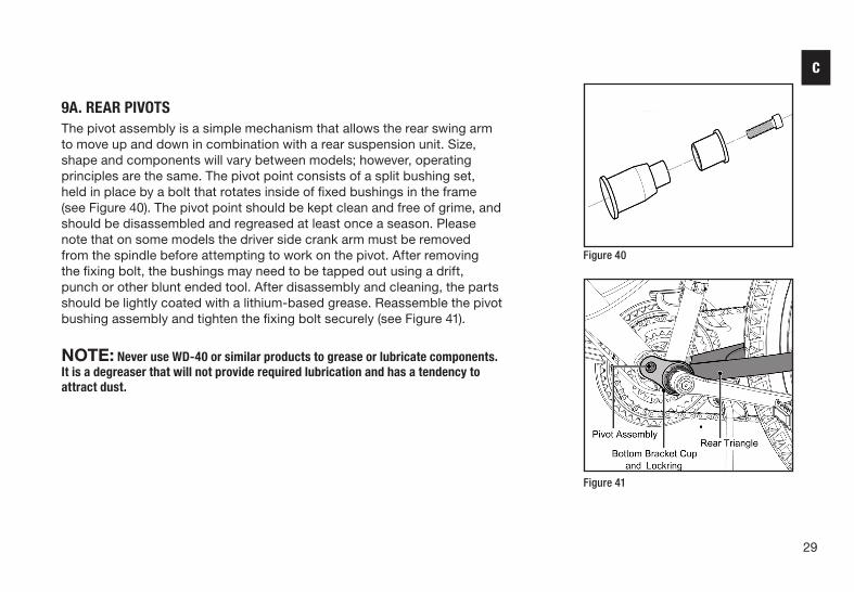
9A. REAR PIVOTSThe pivot assembly is a simple mechanism that allows the rear swing arm to move up and down in combination with a rear suspension unit. Size, shape and components will vary between models; however, operating principles are the same. The pivot point consists of a split bushing set, held in place by a bolt that rotates inside of fixed bushings in the frame (see Figure 40). The pivot point should be kept clean and free of grime, and should be disassembled and regreased at least once a season. Please note that on some models the driver side crank arm must be removed from the spindle before attempting to work on the pivot. After removing the fixing bolt, the bushings may need to be tapped out using a drift, punch or other blunt ended tool. After disassembly and cleaning, the parts should be lightly coated with a lithium-based grease. Reassemble the pivot bushing assembly and tighten the fixing bolt securely (see Figure 41).
NOTE: Never use WD-40 or similar products to grease or lubricate components. It is a degreaser that will not provide required lubrication and has a tendency to attract dust.
Figure 40
Figure 41
C

30
10. TIRE INFLATION
WARNING: Tires must be properly inflated before riding. Never exceed the maximum pressure (PSI) that is listed on the side of the tire.
WARNING: Be sure to check that the edge (beads) of both tires are evenly seated the entire way around on both sides of the tire. Failure to do so may result in the tire coming off of the rim, the tube popping (see Figure 43), and a loss of control of the bicycle, causing injury or even death.
WARNING: Using a service station air hose without a pressure gauge may result in over-inflating of the tire and popping of the tube. This could also cause irreparable damage to the tube and tire.
Use a hand pump, foot pump, or floor pump to properly inflate the tires (see Figure 44). The maximum inflation (PSI) is shown on each tire sidewall (see Figure 42). If your pump does not have a built in gauge, use a separate pressure gauge to ensure the tires are inflated to the correct pressure (see Figure 45).
Incorrectly seated Properly seated
C
Figure 42
Figure 43
Figure 44 Figure 45

31
11. REFLECTORSReflectors are pre-installed on your bicycle on the pedals, wheels, seatpost, and handlebars (see Figure 46). Ensure that the handlebar reflector is pointing straight forward and perpendicular to ground, and position the rear reflector so that it points straight backwards. Use (A) Phillips head screwdriver to loosen and adjust before re-tightening (see Figures 47 & 48).
NOTE: Now that the initial assembly is complete, the bike needs to be adjusted before it is ready to ride. Follow the steps in the following Bicycle Adjustments section to adjust the bike.
C
Rear reflectorFront reflector
Wheel reflector
Pedal reflector
Figure 46
Figure 47 Figure 48

32
12. ACCESSORIESYour bike may come with some or all of these accessories that require attachment and/or assembly.
12A. Kick StandsIf the kickstand is not mounted to your bicycle, place the bicycle in an upright position against a wall or have someone hold it upright. Place the kickstand in the bracket mounted on the frame and use a pair of (E) Standard Slip Joint Pliers to secure the fixing bolt to keep the kickstand in place. Be sure to tighten the fixing bolt securely. Some kickstands use a top plate to locate the bolt and secure the kickstand using a fixing bolt. Be sure to tighten the axle nut. The guard will sit between the frame and the axle nut (see Figure 49).
WARNING: The kickstand is designed to support the BICYCLE ONLY; not the bicycle and the rider.
12B. Rear Derailleur GuardSome 20”, 24” and 26” model bicycles come with a rear derailleur guard to protect the rear derailleur from damage. To install, remove the rear wheel axle nut on the drive side, install the rear derailleur guard over the axle with the U-shaped guard pointing down, and retighten the axle nut. The guard will sit between the frame and the axle nut (see Figure 50).
12C. Other AccessoriesFor all other accessories, either follow the instructions on the packaging in order to install, or bring your bike to a qualified bicycle shop in order to have the part safely installed.
Figure 49
Figure 50
C

33
BICYCLE ADJUSTMENTS
SEAT ADJUSTMENTYou can adjust the up and down tilt of your seat as well as the forward and back position by loosening the seatpost hardware at the bottom of your seat. (See Figure 51.) Be careful not to loosen them all the way so that the nut comes off on either side. Loosen enough to make the adjustments, and re-tighten the nuts. To raise or lower your seat, use the quick release lever (see Figure 52), an adjustable or Allen wrench on the seat clamp (see Figure 52) – depending on the style of clamp your bike comes with. Make sure the minimum insertion marks on the seatpost are completely covered (see Figure 53). Close the quick release lever, or tighten the nut on your seat clamp until it is secure, and the seat will not move side-to-side or sink with the rider seated (see Figure 54 & 55). To ensure that your seat is adjusted to the proper height for you, adjust the saddle so that it’s just below your hips. Retighten the seat post clamp and mount your bike. At the bottom of your pedal stroke, your knee should have a slight bend in it, with the ball of your foot centered over the pedal. The saddle should also always be parallel with the top tube. For more detailed instructions on how to properly adjust your bike to fit you, visit our website at dynacraftwheels.com, find your bike, and locate the fit video in the Information Center. (Disclaimer: Fit video not available for all bikes)
WARNING The seatpost must be inserted far enough so that the minimum insertion marks cannot be seen.
OpenClosed
Minimum insertion marks are located on the seatpost
Seat tube
Seatpost
Figure 55
D
Figure 51
Figure 53
Figure 52
Figure 54

34
STEM ADJUSTMENTTo raise or lower your stem, use an adjustable wrench or Allen wrench on the stem bolt to loosen the stem (see Figure 56). Do not remove this bolt completely, as the stem wedge may fall inside your frame. Make sure the stem is inserted enough so that the minimum insertion marks on your stem are completely covered (see Figure 57).
WARNING: To prevent steering system damage and possible loss of control, the stem and handlebars must be properly adjusted and tightened. DO NOT OVERTIGHTEN (see Page 23, Figure 27).
WARNING: To prevent steering system damage and possible loss of control, the stem must be inserted enough so that the minimum insertion marks are completely covered.
WARNING: Do not over tighten the stem bolt. Over tightening the stem bolt can damage the steering system and cause a loss of control. If necessary re-adjust the handlebar and tighten the handlebar clamp nut.
WARNING: Threadless stem systems cannot be raised or lowered without removing components and re-adjusting. They should not be adjusted or loosened by anyone other than an experienced bicycle shop mechanic (see Figure 58).
Minimum insertion mark
D
Figure 56
Figure 58
Figure 57

35
HANDLEBAR ADJUSTMENTTo adjust the handlebars forward and backwards, loosen the stem bolt or bolts. Your bike may have one (see Figure 59), two (see Figure 60), or four (see Figure 61) bolts holding the handlebar in place. Do not completely remove these bolts, simply loosen them until you are able to move the handlebar to the desired position. Once complete, tighten the bolt(s). If your stem has multiple bolts, be sure to tighten them evenly (alternating each bolt a few turns at a time).
To test the tightness of the handlebar, hold the bike stationary and try to rotate the ends of the handlebar up and down or move the bar forward and back. If the handlebar moves, loosen the handlebar clamp nut or bolts evenly to re-position and then re-tighten. Repeat the test until the bars will not move.
BRAKE LEVER ADJUSTMENTMake sure that the brake levers are adjusted to a comfortable angle for the rider. Both brake levers can be adjusted by loosening the clamp bolt and rotating the lever into the desired position. Once the lever is positioned, re-tighten the bolt. Make sure both levers are set at the same angle.
Check to make sure that the lever is tight. It should not move on the handlebar when tightened properly. The reach of the brake levers can also be adjusted. A screw changes the point where the lever rests. This is useful for riders with small hands. Simply use (A) a Standard Phillips Head Screwdriver to adjust this (see Figure 62).
SHIFTER ADJUSTMENTTo adjust the angle of the shifters, loosen the clamp bolt and rotate the shifter into the desired position. Once the shifter is positioned, re-tighten the bolt. Repeat for the other side, making sure they are set at the same angle. Check to make sure the shifter is tight. It should not move on the handlebar when tightened properly.
Figure 60
Figure 61
Figure 59
Clamp Bolt
Reach Adjuster Screw
D
Figure 62

36
BRAKE ADJUSTMENT
WARNING: Always make sure your brakes are properly adjusted before riding (see Page 27, Testing Brake Functions).
Brake Pads• Ensure that the wheel is properly centered within the dropouts and is not out of
true (see Figure 63).• Using (C) a 4, 5, or 6 mm Allen wrench adjust the brake pad bolts so the brake
pads are in line with the the curve of the wheel, striking the upper edge of the braking surface, but not the tire. Tighten the brake pad bolts once they are positioned correctly.
• In addition to being centered on the rim, the front of the pad (towards the front of the bike) should contact the rim slightly before the rest of the pad.
WARNING: Make sure your brake pads never make contact with your tires. If your brake pads rub on the tires, it will cause irreparable damage to your tire and tube, and may result in a popped tire and could cause a loss of control resulting in serious injury or even death.
Side Pull Brakes• Once the brake pads are properly positioned, loosen the cable anchor nut on the
Brake Arm (see Figure 64). Firmly squeeze the brake pads against the rim of the tire, pull the cable taut, and re tighten the cable anchor nut using either (C) a 4, 5, or 6 mm Allen Wrench or a pair of (E) Standard Slip Joint Pliers.)
• If your brake is not centered, or the pads are not contacting the rim at the same time, loosen the mounting nut holding the brake to the fork (front) or the frame (rear) (see Figure 64). Squeeze the brake lever firmly, and tighten the brake nut while continuing to squeeze the brake lever. Squeeze the brake lever several times to check to see if the brakes are centered (see Figure 63).
Figure 63
D
Figure 64
Brake cable
Brake arm
Cable Anchor Bolt
Brake pad

37
Linear Pull Brakes• Once the brake pads are properly positioned, loosen the cable anchor nut on the
Brake Arm (See Figure 65). Firmly squeeze the brake pads against the rim of the tire, pull the cable taut, and re tighten the cable anchor nut using either (C) a 4, 5, or 6 mm Allen Wrench or a pair of (E) Standard Slip Joint Pliers.)
• If the brake pads do not contact the rim at the same time, use (A) a Standard Phillips Head Screwdrivers to turn the Adjustment Screws on the Brake Arm until they contact the rim at the same time when pulling the brake lever.
Mechanical Disc Brakes• To ensure that the brake caliper is positioned correctly, loosen the bolts holding
it in place, and position it so that the outside brake pad is slightly closer to the rotor than the inside brake pad (see Figures 66 & 67). Then re-tighten those caliper mounting bolts, alternating until they are both tight. Spin the wheel to make sure there is no rubbing on any point on the rotor.)
• Squeeze the brake lever to test the caliper. The brake should fully engage before the lever is pulled back to the handlebar. If you’re able to pull the lever all the way to the handlebar, or they feel too soft, use the barrel adjuster on the Caliper and the Brake Lever to adjust the tension until it feels more firm.
Brake LeversWhen squeezed, the brake lever should be firm and not bottom out against the handlebar grip. To remove slack from the cable and make the lever more firm, use the barrel adjuster on the brake lever or brake caliper. Unscrew the barrel adjuster and locking nut one turn at a time until the desired firmness is achieved. Keeping the barrel adjuster in place, tighten the locking nut back down against the brake lever or brake caliper. If your brake lever is still too soft after adjusting, further adjustment may be needed by a bicycle shop.
WARNING: If the barrel adjuster is loosened too much it may fall out, causing brake failure.
Brake lever
Grip Handlebar
Cable adjuster barrel
Reach Adjuster Screw
Nipple Ferrule Cable Housing
Figure 65
Figure 68
D
Brake CableCable Carrier
Brake arm
Brake pad
Cable Anchor Nut
Figure 66 Figure 67

38
SHIFTER ADJUSTMENT
WARNING: Do not ride a bicycle that is not shifting properly. Overlooking proper adjustments may cause irreparable damage to the bicycle and/or bodily injury. Never move the shifter while pedaling backward, nor pedal backwards after having moved the shifter. This could jam the chain and cause serious damage to the bicycle and/or rider.
NOTE: If you don’t have a bicycle repair stand, it helps to have someone assist you with the adjustment.
There are three types of shifters that may be on your bicycle. There is a Shifter/Brake Lever Combo (see Figure 69), a Standard Shifter (see Figure 70), and a Grip Shifter (See Figure 71). For the Combo and the Standard Shifter, use your thumbs to shift up, and your index fingers to shift down with the appropriate levers. On a Grip Shifter, rotate the shifter on the handlebars in the appropriate direction to shift up or down.
Figure 71
Figure 69
Figure 70
D

39
DERAILLEUR ADJUSTMENTWith the chain in the middle cog on the crankset (#2 on the left shifter), lift the rear wheel off the ground and pedal slowly. While continuing to pedal, shift the right (rear) shifter through the rings. It should shift smoothly, and stay in gear without jumping between gears or excessive noise. If the chain seems to be caught in between gears, you can adjust the cable by loosening or tightening the barrel adjuster on the rear derailleur (see Figure 73). If the chain doesn’t want to go up to the next bigger gear in the back, loosen the barrel adjuster (counterclockwise) ½ turn. If the chain doesn’t want to come down to the next smaller gear in the back, tighten the barrel adjuster (clockwise) ½ turn. Repeat until the chain moves from gear to gear without hesitation. Avoid shifting your bike into extreme gears- both the smallest ring and smallest cog at the same time, or both the largest ring and largest cog at the same time. For most riding situations, your left shifter, which controls the front derailleur, should remain in the middle cog indicated by #2 on most shifters. Use 1st gear on the left shifter only when going up a steep incline, or 3rd gear when going at a faster pace. If you are having trouble with your shifting, or can’t get it adjusted properly, bring your bike to a qualified bicycle shop for service.
Figure 72
Figure 73
D
40
MAINTENANCE AND INSPECTION
WARNING: Inspect the bicycle frequently. Failure to inspect the bicycle and to make repairs or adjustments, as necessary, can result in injury to the rider or to others. Make sure all parts are correctly assembled and adjusted as written in this manual.
• Immediately replace any damaged, missing, or badly worn parts.
• Make sure all fasteners are correctly tightened as written in this manual. Parts that are not tight enough can be lost or operate poorly. Over tightened parts can be damaged. Make sure any replacement fasteners are the correct size and type.
NOTE: Have a bicycle service shop make any repairs or adjustments for which you do not have the correct tools or if the instructions in this manual are not sufficient for you.
NOTE: Before every ride, it is important to carry out the safety checks detailed on page 14. (For information and instructions on performing specific equipment checks, locate the relevant section in the manual referenced on pages 5–6.)
E

41
WARNING: Do not attempt chain repairs. If there is a problem with the chain, have a bicycle service shop make any repairs.
The chain must be at the correct tightness. If too tight, the bicycle will be difficult to pedal. If too loose, the chain can come off the sprockets. When the chain is at the correct tightness, you can rotate the crank freely and you can pull it no more than one-half inch away from a straightedge as shown (see Figure 74).
Adjust the tightness of the chain as follows:
• Loosen the axle nuts of the rear wheel.• Move the rear wheel forward or backward as necessary.
NOTE: Make sure the rear wheel is centered in the bicycle frame (see Figure 75).
• Hold the wheel in this position and tighten the axle nuts.
TIRE REMOVAL/SEATINGBefore adding air to any tire, make sure the edge of the tire (the bead) is the same distance from the rim, all around the rim, on both sides of the tire. If the tire does not appear to be seated correctly, release air from the inner tube until you can push the bead of the tire into the rim where necessary. Add air slowly and stop frequently to check the tire seating and the pressure, until you reach the correct inflation pressure (see Figure 76).
Incorrectly seated Properly seated
E
Figure 74
Figure 75
Figure 76

42
LUBRICATION
WARNING: Do not over lubricate. If oil gets on the wheel rims or the brake shoes, it will reduce brake performance and a longer distance to stop the bicycle will be necessary. Injury to the rider or to others can occur.
• The chain can throw excess oil onto the wheel rim. Wipe excess oil off the chain.• Keep all oil off the surfaces of the pedals where your feet rest.• Using soap and hot water, wash all oil off the wheel rims, the brake shoes, the pedals, and the tires.• Rinse with clean water and dry completely before you ride the bicycle.• Use only a bicycle specific lube, as other common oils will not provide the correct lubrication.
Frequency Component Lubricant How to LubricateWeekly Chain Chain lube or light oil Brush on or squirt
Derailleur Wheels Chain lube or light oil Oil can
Derailleurs Oil 3 drops from oil can
Brake Calipers Oil 2 drops from oil can
Every Six Months Freewheel Oil 2 squirts from oil can
Brake Cables Lithium based grease Disassemble
Yearly Bottom Bracket Lithium based grease Disassemble
Headset Lithium based grease Disassemble
Hubs (front and rear) Lithium based grease Disassemble
E

43
BEARING INSPECTION• Maintenance
Frequently check the bearings of the bicycle. Have a bicycle shop clean and re-grease the bearings once a year or any time they do not pass the following tests:
• Header BearingsThe fork should turn freely and smoothly at all times. With the front wheel off the ground, you should not be able to move the fork up, down, or side-to-side in the head tube.
• Bottom Bracket BearingsThe crank should turn freely and smoothly at all times and the front sprockets should not be loose on the crank. You should not be able to move the pedal end of the crank from side-to-side.
• Wheel Hub BearingsLift each end of the bicycle off the ground and slowly spin the raised wheel by hand. The bearings are correctly adjusted if:
– The wheel spins freely and easily. – The weight of the spoke reflector, when you put it toward the front or rear of the bicycle, causes the wheel to spin back and forth several times.
– There is no side-to-side movement at the wheel rim when you push it to the side with light force.
E

44
1
UPGRADE YOUR WARRANTY WITH PRODUCT REGISTRATIONFree warranty upgrade with online registration at dynacraftwheels.com/register
We respect your privacy. Any information collected by Dynacraft Wheels will never be shared with any other company or organization. See Dynacraft’s privacy policy for further information: dynacraftwheels.com/dynacraft-privacy-policy.
BENEFITS OF SIGNING UP FOR FREE EXTENDED WARRANTY• Simple, quick sign up at dynacraftwheels.com/register (proof of purchase required).• Extra 60 days of coverage on bike parts subject to wear and tear, from date of purchase.• Transportation charges on replacement parts waived for the Limited Warranty period.
See Limited Warranty for Details.
For further enquiries call Customer Service at 1-800-551-0032 or visit dynacraftwheels.com/contact
FREE WARRANTY UPGRADE WITH REGISTRATION
CONSUMER ACTION REQUIREDdynacraftwheels.com/register
LIMITED WARRANTYF

45
LIMITED WARRANTY
This Limited Warranty (“Warranty”) extends only to the original retail purchaser, who must provide proof of purchase to validate any claim As noted below, certain aspects of this Warranty can be extended free of charge to original retailer purchasers who also register their product using the provided online registration form Proper registration via Dynacraft’s online registration form is the only way to obtain these noted extensions This Warranty is not transferrable to anyone else and is the only warranty for your Dynacraft product, to the extent permitted by law No other express or implied warranty is given, and except to the extent prohibited by applicable law, any implied warranty of merchantability or fitness for a particular purpose on this product is hereby disclaimed Part or model specifications are subject to change without notice By purchasing and using your new bicycle you agree to be bound by the terms of this Warranty as set out below This Warranty is subject to change without notice
What does this Limited Warranty cover? This Warranty covers all parts of the bicycle to be free from defects in workmanship and materials This Warranty is only effective if: the bicycle is used under normal conditions for its intended purposes, by a person that properly fits and is capable of controlling the bicycle; and the bicycle receives all necessary maintenance and adjustments
Useful Life: This bicycle, like any other item has a useful life A lifetime warranty on the frame and fork does not mean and is not intended to imply that the bicycle will last forever The length of the useful life of this bicycle will vary depending on the type of bike, riding and storage conditions, and the care the bicycle receives
What is not covered by this Limited Warranty? This Warranty does not include labor and transportation charges You, the original purchaser will be responsible for labor or transportation charges associated with the repair or replacement of the frame, fork, or other components covered under this Warranty Those original purchasers who qualify for the extended version of this Warranty will have transportation charges waived for the duration of the Limited Warranty period
The bicycle frame, fork, and components have been manufactured for general transportation and recreational use by average riders, and the
bicycles are not intended for trick riding, ramp riding, jumping, aggressive riding or any similar, extreme activities This Warranty does not cover normal wear and tear, paint, rust, or normal maintenance items This Warranty does not cover claimed defects, malfunctions, or failures that result from abuse, neglect, improper assembly, improper maintenance, lack of maintenance, alteration, misuse, crashes, or any similar damage
This Warranty will be void if the bicycle is ever: used in any competitive sport; used in any of the extreme activities, or similar activities mentioned above; installed with a motor or modified in any other way; ridden by more than one person at a time; rented or used for commercial purposes; or used in a manner contrary to the instructions in the Owner’s Manual included with this product Dynacraft will not be liable for incidental or consequential loss or damage, due directly or indirectly from use of this product
For how long does this Limited Warranty last? The frame and fork are warrantied for the Useful Life of this bicycle All other components, with the exclusion of components subject to normal wear and tear are warrantied for a period of one year after the original date of purchase Defective components subject to normal wear and tear will be replaced by Dynacraft at no charge for a period of 30 days from the original date of purchase For those original purchasers who qualify for the extended version of this Warranty, this period will be lengthened to 90 days from date of purchase Components subject to the normal wear and tear exclusion include but are not limited to: tires; tubes; grips; brake shoes; cables; and saddles
What will Dynacraft do to honor this Limited Warranty? Dynacraft will replace, without charge to the customer, any frame, fork or component confirmed to be defective with the same or a functionally equivalent part You, the original purchaser will be responsible for any and all labor or transportation charges connected with the replacement or repair of the frame, fork, or other components covered under this Warranty
How do you make a claim under this Limited Warranty? Warranty claims should be submitted via Dynacraft’s online portal at dynacraftwheels com/contact Please have your proof of purchase available before contacting to validate your claim Products can be registered at dynacraftwheels com/register
F

Dynacraft BSC, Inc.1501 Crossgate RoadPort Wentworth, GA 31407Call Toll Free 1-800-551-0032Monday – Friday 9AM to 5PM ESTdynacraftwheels.com©2020 All rights reserved
2020 Printed in China
D007
DO NOT RETURN THIS ITEM TO THE STORE CONTACT DYNACRAFT CUSTOMER SERVICE FOR ASSISTANCE
dynacraftwheels.com/contact or 1-800-551-0032 9 AM – 5 PM ET
Please have the following information available:
Model Number Example: 8000-00 Production Date Example: MM.DD.YYYY Serial Number Example: DA00000000000
This information is required to help us handle your request effectively.