owner's manual - welding supplies, parts, … have purchased the worlds finest mig welding...
TRANSCRIPT

MM250SL M.I.G. COMBINATION UNIT
CONGRATULATIONS!
YOU HAVE PURCHASED THE WORLDS FINEST MIGWELDING SYSTEM AVAILABLE EXCLUSIVELY FROMSNAP-ON TOOLS. THE SNAP-ON MUSCLE MIG SYS-TEM MODEL# MM250SL IS DESIGNED AND ENGI-NEERED BY THE PROS FOR THE PROS. UNDERNORMAL CARE THIS SYSTEM WILL PROVIDE YOUWITH YEARS OF UNSURPASSED SERVICE ANDMOST IMPORTANTLY PERFORMANCE.
OWNER'S MANUAL
FOR TECH. SERVICE, CALL TOLL-FREE 1-800-232-9353
INSTALLATIONOPERATION
MAINTENANCEFORM WC5377 Rev. 11/98, 1/00, 8/00, 4/01

Snap-on Tools Corporation Kenosha WI 53141-1410
MANUFACTURER’S LIMITED WARRANTY
This equipment is warranted against defects in materialsand workmanship for a period of two years from the date ofpurchase.
EXCEPTION: THE MIG TORCH IS WARRANTED FOR APERIOD OF 30 DAYS FROM THE DATE OF PURCHASE.
Should the equipment become defective for such reason,the Manufacturer will repair it without charge, if it is returnedto the Manufacturer’s factory, freight prepaid. This warrantydoes not cover: (1) failure due to normal wear and tear; (2)consumable parts, such as, but not limited to, torch contacttips, gas cups and insulating bushings; (3) damage byaccident, force majeure, improper use, neglect, unauthor-ized repair or alteration; (4) anyone other than the originalpurchaser.
THIS LIMITED WARRANTY IS IN LIEU OF ALL OTHERWARRANTIES, EXPRESS OR IMPLIED. THE MANUFAC-TURER SHALL NOT BE LIABLE FOR ANY INJURY TOPERSONS, INCLUDING DEATH; OR LOSS OR DAMAGETO ANY PROPERTY, DIRECT OR CONSEQUENTIAL,INCLUDING, BUT NOT LIMITED TO, LOSS OF USE,ARISING OUT OF THE USE, OR THE INABILITY TO USE,THE PRODUCT. THE USER ASSUMES ALL RISK ANDLIABILITY WHATSOEVER IN CONNECTION WITH THEUSE OF THE PRODUCT, AND BEFORE DOING SO,SHALL DETERMINE ITS SUITABILITY FOR HIS IN-TENDED USE, AND SHALL ASCERTAIN THE PROPERMETHOD OF USING IT.
SOME STATES DO NOT ALLOW LIMITATIONS ONHOW LONG AN IMPLIED WARRANTY LASTS, OR THEEXCLUSIONS OR LIMITATIONS OF INCIDENTAL ORCONSEQUENTIAL DAMAGES. SO THE ABOVE LIMITA-TIONS OR EXCLUSIONS MAY NOT APPLY TO YOU. THISWARRANTY GIVES YOU SPECIFIC LEGAL RIGHTS, ANDYOU MAY HAVE OTHER RIGHTS WHICH MAY VARYFROM STATE TO STATE.
ARC WELDING CAN BE INJURIOUS TO OPERA-TOR AND PERSONS IN THE WORK AREA -——CONSULT INSTRUCTION MANUAL BEFOREOPERATING.
ELECTRIC SHOCK can kill.• Do not touch electrodes or other electrically live parts.
• Insulate yourself from work and ground.
• Install and ground machine in accordance with the National
Electical Code and local code(s). Read Operating Manual
before installing or operating.
• Do not operate with protective covers, panels, or guard
removed.
• Disconnect input power before servicing.
• Only qualified personnel should install, use, or service this
equipment.
ARC RAYS can injure your eyes and burnskin.• Wear correct eye, ear, and body protection while welding.
FUMES AND GASES can be dangerous to yourhealth.• Use enough ventilation and/or exhaust at the arc.
• Keep your head out of fumes.
• Do not breathe fumes.
READ AND UNDERSTAND THEMANUFACTURER’S INSTRUCTIONS ANDYOUR EMPLOYER’S SAFETY PRACTICES.
See American National Standard Z49.1, “Safety inWelding and Cutting”, published by the AmericanWelding Society, 2501 N.W. 7th St., Miami, Florida33125; OSHA Safety and Health Standards, 29 CFR1910 available from U.S. Dept. of Labor, Wash.,D.C. 20210.
! WARNING
TABLE OF CONTENTSINTRODUCTION ........................................................................... 1DESCRIPTION, SPECIFICATIONS .............................................. 2CHECK LIST (CONTENTS) .......................................................... 3INSTALLATION & ELECTRICAL REQUIREMENTS ................... 4OPERATION ................................................................................. 8MAINTENANCE........................................................................... 13TROUBLE SHOOTING CHART.................................................. 15CONNECTING FLEXTIG OR SPOOL GUN ............................... 20LINER INSTALLATION ............................................................... 21PARTS BREAKDOWN - MIG TORCH ........................................ 22OPTIONS - FLEXTIG OR SPOOL GUN ..................................... 24PARAMETER CHARTS .............................................................. 25

Snap-on Tools Corporation Kenosha, WI 53141-1410 1
INTRODUCTIONThe Snap-on Tools MM250SL is a
combination welding power source,remote feed unit, MIG torch andaccessory package, which is de-signed to meet the requirements ofthe light to medium metal fabrica-tion industries. The MM250SL pro-duces fusion welds by the Gas MetalArc Welding process (GMAW or MIG),on steel and aluminum up to "3/8"thick, using .023" through .045"steel wire and .025" through 3/64"aluminum wire with the optionalMHG5-B spool gun. (optional linersmust be purchased to cover givenwire sizes). Heavier sections canbe easily welded using slightlydifferent techniques.
The number of controls on the unithave been reduced to assist inexpe-rienced operators to learn MIGwelding. This facilitates rapidset up for welding various thick-nesses of material requiring vari-ous heat inputs. The VOLTAGEcontrol adjusts the welding voltageand the WIRE FEED control adjuststhe speed of the wire feed motor.
A SPOT WELD control switch andadjustable timer circuit providesConsumable MIG Spot Welding capa-bilities of light gauge steel.
THE MIG PROCESSAS APPLIED TO THE MM250SL
The MIG process uses a bare,consumable electrode in the form ofspooled wire, which is fed by acontrollable speed feed unitthrough the cable and torch to theweld. The emerging wire and theweld are shielded by a stream ofCO2, Argon, or a mixture of the two,which prevents oxidation of themolten weld puddle. The gas shieldenables high quality welds to bemade without the use of flux,eliminating the need for slag orflux removal after the weld iscompleted.
POWER SOURCE
WIRE SPOOL
FEEDROLLS
WORK
MIGTORCH
+REVERSEPOLARITY
(STD.)_
SHIELDING GAS
The consumable electrode wire ismelted and transferred to the weldpuddle by any of three arc modes;short arc transfer, globular trans-fer, or spray arc transfer. TheMM250SL is capable of performingall modes.
SHORT ARC OR DIP TRANSFER
Short arc transfer occurs at 12 to22 arc volts (voltage while weld-ing), depending on wire size. Weld-ing commences as the arc is struckand a weld pool is formed. The tipof the electrode wire dips into thepool and causes a short circuit.The short circuit current flowcauses a rapid temperature rise inthe electrode wire and the end ofthe wire is melted off. An arc isimmediately formed between the tipof the wire and the weld pool,maintaining the electrical circuitand producing sufficient heat tokeep the weld pool fluid. Theelectrode continues to feed andagain dips into the pool.
FIG. 1. SCHEMATIC OF M.I.G. PROCESS
FIG. 2. SHORT ARC TRANSFER
ELEC-TRODE
WORK

2 Snap-on Tools Corporation Kenosha, WI 53141-1410
SHORT ARC OR DIP TRANSFER (Cont.)
This sequence of events is re-peated up to 200 times per second.Short arc transfer is suitable forpositional welding. The heat inputto the workpiece is kept to aminimum which limits distortion andmakes possible the welding of thinsheet material.
GLOBULAR TRANSFER
Globular transfer occurs at theintermediate range of 22 to 24 arcvolts, depending on wire size. Asthe name implies, the transfertakes place in the form of irregu-larly shaped globules. Globulartransfer is useful in cases where alower heat input than that of truespray is required.
DESCRIPTIONThe MM250SL consists of a combi-
nation MIG welding power source andremote feed unit, a MIG torch with10 foot cable, a fifteen foot feedercontrol cable, a fifteen foot workcable with clamp, a twenty footpower input cable, a gas regulator -flowmeter, a torch accessory kit,and a built-in cylinder rack andindustrial wheel kit.
Welder controls are simple andclearly marked. The output voltageis controlled by a twelve positiontap switch, providing 4 TIG and 8MIG voltage selections. Wire feedspeed is controlled by the wirespeed potentiometer.
SPECIFICATIONSPART NUMBER: MM250SL
INPUT POWER REQUIREMENTS:Voltage 208/230Phase single phaseFrequency 50/60 hertzCurrent 33/30
NOTEThis welder draws 20 amps at100% Duty cycle (185 ampsoutput). A 40 amp 208 or 230volt electrical service isrequired for proper arc start-ing and full utilization ofits maximum output of 250amps.
DUTY CYCLE - OUTPUT POWER:(NEMA) @ 60% - 200 Amps
@ 60% - 230 Amps@ 35% - 250 Amps
DUTY CYCLE TIME PERIOD:10 minutes
OPEN CIRCUIT VOLTAGE:18 - 42 volts DC
ARC VOLTAGE: 14 - 28 volts DC
WELD CURRENT RANGE:30 - 250 amps
SPRAY TRANSFER
Spray transfer occurs at 22 to 32arc volts, depending on wire size.The length of the arc is heldconstant by the voltage available.The higher voltage and currentcauses the electrode wire to meltoff before touching the workpiece.The molten metal crosses the gap tothe workpiece in a spray form.Spray transfer is used in the down-hand position and provides higherdeposition rates than short arctransfer or globular transfer.
ELECTRODE GAS NOZZLE
SHIELDING GASWORK
FIG. 3. GLOBULAR TRANSFER
ELECTRODE GAS NOZZLE
SHIELDING GASWORK
FIG. 4. SPRAY TRANSFER
Snap-on Tools Corporation Kenosha, WI 53141-1410 3
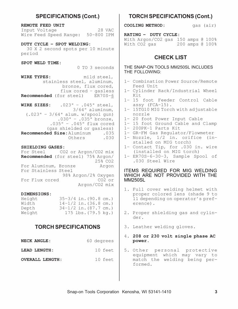
SPECIFICATIONS (Cont.) TORCH SPECIFICATIONS (Cont.)COOLING METHOD: gas (air)
RATING - DUTY CYCLE:With Argon/CO2 gas 150 amps @ 100%With CO2 gas 200 amps @ 100%
CHECK LISTTHE SNAP-ON TOOLS MM250SL INCLUDESTHE FOLLOWING:
1- Combination Power Source/RemoteFeed Unit
1- Cylinder Rack/Industrial WheelKit
1- 15 foot Feeder Control Cableassy (FCA-15).
1- 15TG10 MIG Torch with adjustablenozzle
1- 20 foot Power Input Cable1- 15 foot Ground Cable and Clamp1- 200PK-1 Parts Kit1- GR-FM Gas Regulator/Flowmeter1- Nozzle, 1/2 in. orifice (in-
stalled on MIG torch)1- Contact Tip, for .030 in. wire
(installed on MIG torch)1- ER70S-6-30-3, Sample Spool of
.030 Steel Wire
ITEMS REQUIRED FOR MIG WELDINGWHICH ARE NOT PROVIDED WITH THEMM250SL
1. Full cover welding helmet withproper colored lens (shade 9 to11 depending on operator’s pref-erence).
2. Proper shielding gas and cylin-der.
3. Leather welding gloves.
4. 208 or 230 volt single phase ACpower.
5. Other personal protectiveequipment which may vary tomatch the welding being per-formed.
REMOTE FEED UNITInput Voltage 28 VACWire Feed Speed Range: 50-800 IPM
DUTY CYCLE - SPOT WELDING:30 X 2 second spots per 10 minute
period
SPOT WELD TIME:0 TO 3 seconds
WIRE TYPES: mild steel,stainless steel, aluminum,
bronze, flux cored,flux cored - gasless
Recommended (for steel) ER70S-6
WIRE SIZES: .023" - .045" steel,3/64" aluminum,
(.023" - 3/64" alum. w/spool gun).030" - .035" bronze,
.035" - .045" flux cored(gas shielded or gasless)
Recommended Size:Aluminum .035Others .030
SHIELDING GASES:For Steel CO2 or Argon/CO2 mixRecommended (for steel) 75% Argon/
25% CO2For Aluminum, Bronze ArgonFor Stainless Steel
98% Argon/2% OxygenFor Flux cored CO2 or
Argon/CO2 mix
DIMENSIONS:Height 35-3/4 in.(90.8 cm.)Width 14-1/2 in.(36.8 cm.)Depth 34-1/2 in.(87.7 cm.)Weight 175 lbs.(79.5 kg.)
TORCH SPECIFICATIONS
NECK ANGLE: 60 degrees
LEAD LENGTH: 10 feet
OVERALL LENGTH: 10 feet

4 Snap-on Tools Corporation Kenosha, WI 53141-1410
INSTALLATION
POSITIONING THE UNIT
Locate the unit adjacent to thewelding area and position it sothere is adequate clearance allaround for ventilation and mainte-nance.
FIG. 5. INPUT VOLTAGE SELECTIONS
CAUTIONMAKE SURE POWER SOURCE ISUNPLUGGED BEFORE MAKING IN-PUT SELECTION CHANGE-OVER.
3. Attached to the power source’scontactor is one (2) two posi-tion plug which allows easyselection of input voltages ofeither 208 or 230 volts.
4. Remove the one (1) plug labeled230V and connect the one (1) pluglabeled 208V.
5. Reattach the top cover of themachine. Voltage input selec-tion is now complete.
2. With the proper size wrenchattach the gas-current fittingto the gas-current terminal (lo-cated on the front of the feedunit).
FIG. 6. FCA-15 FEEDER CABLE ASSEMBLY
GAS-CURRENTFITTING
CONTROLPLUG(FEMALEPINS)
CONTROLPLUG(MALEPINS)
POWERPLUG
GAS-CURRENTCABLE
FEEDERCONTROLCABLE
ELECTRICAL SUPPLY
Ensure that there is a 208 or 230volt, single phase, 40 amp electricalsupply within easy reach of theunit(see note on page 2 underspecifications). The input cablesupplied is 20 feet long. A 50 footcable is an optional extra. Attacha suitable plug making sure the greenwire is attached to the ground terminal ofthe wall plug. All wiring should beperformed by a qualified electri-cian.
230V INPUT SELECTION
1. Factory selected no change isneeded.
208V INPUT SELECTION
1. Remove the top cover.
2. Locate the contactor switch,which is mounted on top of themain power transformer(See Fig-ure 5).
INSTALLING THE FEEDER CONTROL CABLEASSEMBLY
1. Uncoil the cable assembly.
CONTACTOR SWITCH
CONNECT"230" WIRE FOROPERATION ON230 VOLT INPUT.
CONNECT "208"WIRE FOROPERATION ON208 VOLT INPUT
FRONT OFMACHINE

Snap-on Tools Corporation Kenosha, WI 53141-1410 5
INSTALLING THE FEEDER CONTROL CABLEASSEMBLY (Cont.)
3. Connect the control plug (femalepins)onto the control recep-tacle (INPUT) and tighten (lo-cated on the front of the feedunit).
FIG. 7. CABLE CONNECTION TO FEED UNIT
SHIELDING GAS CONNECTIONS
1. Place a cylinder of the appro-priate shielding gas in the rackat the rear of the machine andsecure it with the chain pro-vided.
2. Rapidly open and close the cyl-inder valve. This will purgedust and foreign matter from thevalve.
CAUTIONTake care to point thevalve outlet away fromyourself or other people,as escaping high pressuregas may be dangerous.
FIG. 8. CABLE CONNECTION TOWELDING MACHINE (continued on following page)
3. Attach the gas regulator - flow-meter supplied with this unit,to the cylinder valve using asuitable wrench.
FIG. 9. GAS FLOW ADJUSTMENT
FEEDUNIT
TO GAS-CURRENTTERMINAL
TO CONTROLRECEPTACLE(INPUT)
4. Plug the power plug into thepositive (+) terminal(locatedon the front of the weldingmachine).
5. Connect the control plug (malepins) onto the control recep-tacle (OUTPUT)and tighten (lo-cated on the front of the weldingmachine).
WELDINGMACHINE
TO CONTROLRECEPTACLE(OUTPUT)
TO (+)TERMINAL(STANDARD)
GAUGE -INDICATES
TANKPRESSURE
OUTLETFITTING
TOWELDINGMACHINE
GAS FLOWADJUSTING
KNOB
INLETFITTING
TOTANK
FLOW TUBEINDICATES
FLOW RATEIN C.F.H.

6 Snap-on Tools Corporation Kenosha, WI 53141-1410
SHIELDING GAS CONNECTIONS (Cont.)
NOTEIf this unit is to be usedwith 100% CO2 shieldinggas, an optional gas regu-lator coupler is required.
4. Fit the gas hose from the weldingmachine to the regulator outletfitting and tighten it with awrench. Open the cylinder valve.When welding steel, the gas flowrate is 30 CFH. When weldingaluminum, the gas flow rate is 40CFH.
NOTEThe MM250SL must be turned"ON" and the MIG torchtrigger depressed, beforethe gas flow rate can beadjusted.
TORCH CONNECTION
1. Open the access door of the Feedunit to its fullest extent.
2. Back out the thumb screw locatedon the drive assembly mountingbracket inside the machine. In-sert the MIG torch into the torchpanel mount on the front paneland TIGHTEN THE THUMB SCREW.
FIG. 10. TORCH CONNECTION
FITTING AND THREADING THE ELEC-TRODE WIRE - ALWAYS USE ER70S-6WELDING WIRE WHEN WELDING STEEL.
1. Remove the wire spool clip fromthe spool hub.
2. Unpack the spool of welding wirefrom its protective packaging.
3. Place the spool of ER70S-6 weld-ing wire onto the hub. The wireis fed off the bottom of thespool.
CAUTIONLook for wire protrudingfrom the center of thespool. The protruding wireis electrically HOT duringwelding and must not touchthe machine.
4. Replace the spool clip on thehub.
5. Unlatch the pressure roll armand swing it open.
6. Make sure the double v-groovedrive roll is installed to matchthe wire size. To change thewire size setting, remove thedrive roll, turn it over andreinstall it on the shaft.
7. Release the wire from the spooland trim off the kinked end withwire cutters. The wire must bestraight when it enters theinlet guide.
FIG. 11. DOUBLE GROOVE DRIVE ROLL
DRIVEROLL
TORCHPANELMOUNT
THUMBSCREW
PRESSUREROLL
INLETGUIDE
MIGTORCH
DRIVEASSEMBLYMOUNTINGBRACKET
"B" SIDE FACING IN FOR.023" - .035" STEEL WIRES
"C" SIDE FACING IN FOR.040" - .045" STEEL WIRESAND 3/64" ALUMINUM WIRES

Snap-on Tools Corporation Kenosha, WI 53141-1410 7
FITTING AND THREADING THE ELECTRODEWIRE (Cont.)
FITTING AND THREADING THE ELECTRODEWIRE (Cont.)
Thread the electrode wirethrough the inlet guide, overthe feed roll and into the outletguide. Ensure that the wirelocates in the feed roll groove.Do not allow the wire on thespool to loosen.
Close and relatch the pressureroll arm.
Stretch the torch cable straightout in front of the machinemaking sure there are no kinks.Remove the nozzle and contacttip from the torch.
Turn on the circuit breaker onthe front of the machine. Thecooling fan will start and the"ON" indicator light will illu-minate. Set the MIG/TIG VOLTAGEcontrol switch to "MIG 3" and theWIRE SPEED control to "5". Pullthe trigger on the MIG torch.The wire feed system will startand wire will be fed through thecable liner and torch. If thewire does not feed, or appears toslip, tighten the pressure rollarm adjusting nut. Feed the wireuntil it protrudes from thefront of the torch approximatelysix inches.
CAUTIONKeep hands and face awayfrom the front of the torchand do not allow the wire tocontact ground. The wireis electrically HOT whenthe torch trigger is actu-ated.
8.
9.
10.
11.
Install the contact tip over theprotruding wire and tighten itfirmly using a proper sizewrench. Make sure the tip is thecorrect size for the wire beingused.
Install the nozzle on the torch.For steel, the contact tipshould be flush or stick out upto 1/16 inch beyond the end ofthe nozzle. For aluminum, thecontact tip should be recessed1/8 to 1/4 inch inside thenozzle. Using wire cutters,trim off the wire so the stickoutis approximately 1/4 inch forsteel or 1 inch for aluminum.For aluminum, the end of the wireshould be bent over so it doesnot JAM into the work. This iscalled a "scratch start".
12.
13.
FOR ALUMINUM:CONTACT TIP
RECESSED 1/8" - 1/4"
FOR STEEL:CONTACT TIP
FLUSH WITH NOZZLE
1/4"STICK-OUT
1"STICK-OUT
FIG. 12. WIRE STICKOUT - STEEL, ALUMINUM
For steel welding only, sprayanti-spatter compound insidethe nozzle and on the outside ofthe contact tip. For aluminum orstainless steel welding, NOanti-spatter compound can beused as it will contaminate theweld.
14.

8 Snap-on Tools Corporation Kenosha, WI 53141-1410
WIRE FEED PRESSURE ROLL ADJUST-MENT OPERATION
The following operating instruc-tions and detailed setup proceduresenable an operator without previousexperience to produce quality fu-sion welds. It is recommended thatan operator without prior experi-ence with this equipment, firstpractice on scrap metal of the sametype and thickness as the materialto be welded.
The wire feed pressure roll isadjusted to the proper setting atthe factory, prior to delivery. Itmay be necessary to readjust thesetting as components "seat in" orwhen changing to a different diame-ter wire. To check for proper rollpressure, hold the torch in one handand the wire between two fingers ofthe other hand. Pull the torchtrigger. If the wire continues tofeed when firm pressure is appliedto the wire, the pressure rolladjusting nut should be backed offuntil the feed rolls start to slip.If the wire will not feed with verylittle pressure applied, the pres-sure roll adjusting nut should betightened.
OPERATING SEQUENCE
Make sure that the pieces ofmetal to be welded are free ofgrease, dirt, paint and scale.Use a wire brush to remove paintand scale. Paint must be com-pletely removed to bare metal.Grease and oil could burn andcause a fire or safety hazard.Failure to clean the metal prop-erly will result in erratic andporous welds.
Install the unit as directed inthe installation instructionsand make sure the work clamp isfirmly attached to a cleanedarea on the workpiece to bewelded.
Open the shielding gas cylindervalve. Press the torch triggerand listen for gas flow.
CAUTIONThe welding wire will feedwhen the trigger is actu-ated. Take care that thewire is not directed to hityourself or anything thatis common to the work cableon the welder.
WORK (GROUND) CABLE
Uncoil the work (ground) cableand plug it into the negative (-)terminal on the machine.
1.
2.
3.
FIG. 13. PRESSURE ROLL ADJUSTMENT
PRESSUREROLL ARM
PRESSUREROLL
PRESSURE ROLLADJUSTING NUT
DRIVEROLL

Snap-on Tools Corporation Kenosha, WI 53141-1410 9
PROCESS SELECTIONThe following controls are lo-
cated on the front of the MM250SL.
"ON" INDICATOR LIGHTIlluminates when the circuitbreaker on the machine is "ON".
(-)NEGATIVE TERMINALNegative output terminal. Thework cable is plugged into thisterminal during standard weld-ing operation. The Power plugcan be inserted into this termi-nal for straight polarity weld-ing on very light sheet metal, orfor using flux cored gaslesswire.
OCV/GAS PURGEOperates the gas solenoid topurge the lines of impuritiesprior to welding. Pressing theswitch also causes open circuitvoltage to be registered on thepower source voltmeter.
CAUTIONTorch is electrically HOTwhen switch is actuated.
SPOT/STITCH TIMEAfter the torch trigger isactuated, the timer allows thewire to feed and the gas andpower to flow for the timeselected. The Mode Switch mustbe set in "SPOT or STITCH"position for timing operation.
MODE SWITCHControls mode of operation ofwelding machine. "CONT." posi-tion is for normal, continuouswelding operation. "SPOT" posi-tion puts the spot timer in thecircuit for automatic MIG Con-sumable Spot Welding. "STITCH"position is used for stitchwelding on very light materials.
WIRE SPEEDPotentiometer controls speed ofwire drive motor to give wirespeed of 50 to 800 inches perminute.
(continued on following page)
A.
B.
C.
D.
E.
F.
G.
H.
I.
J.
K.
A.GAS-CURRENTTERMINAL
B.CONTROLRECEP-TACLE(INPUT)
C.MIG/TIGVOLTAGESWITCH
D.VOLT-METER
E."ON"INDICATORLIGHT
F.CIRCUITBREAKER
G.(-)NEGATIVETERMINAL
H.OCV/GASPURGE
I.SPOT/STITCHTIME
J.MODESWITCH
K.WIRESPEED
L.TORCHPANELMOUNT
M.CONTROLRECEP-TACLE(OUTPUT)
N.(+)POSITIVETERMINAL
FIGURE 14. FRONT PANELGAS-CURRENT TERMINALSingle terminal connection forgas and current from weldingmachine.
CONTROL RECEPTACLE (INPUT)Input receptacle for wire feedvoltage, trigger circuit andwire speed control from weldingmachine.
MIG/TIG VOLTAGE SWITCHTwelve position switch provides"4" TIG (requires optional FLEXTIG) and "8" MIG voltage set-tings.
VOLTMETERIndicates open circuit voltagewhen torch trigger switch isactivated and arc (welding)voltage during welding.
CIRCUIT BREAKERPrimary power switch and over-load protection device.

10 Snap-on Tools Corporation Kenosha, WI 53141-1410
PROCESS SELECTION (Cont.)
L. TORCH PANEL MOUNTCombination power output, con-tactor switch connection, gassupply connection, and wire feedoutput in a single unit.
M. CONTROL RECEPTACLE (OUTPUT)Output receptacle for wire feedvoltage, trigger circuit andwire speed control out to theremote feed unit.
N. (+)POSITIVE TERMINALPositive output terminal fromthe welder DC power source. ThePower plug is inserted into thisterminal for standard weldingoperation. The work cable can beplugged into this terminal forstraight polarity welding onvery light sheet metal, or forusing flux cored gasless wire.
WELDINGOptimum control settings will
vary according to the thickness ofthe metal, the type of joint,operator preference, etc. Bestresults can be obtained throughexperience with the welding machineor by making trial welds. Selectsome sample material of the sametype and thickness as the materialto be welded. Set the weldingcontrols(using the parameter chartlocated on the door of the feed unitor on page 25) for optimum resultsusing the sample material thicknessand wire size being used as astarting point, weld until experi-ence is gained using the unit.
CONTINUOUS WELDING ONSTEEL
1. Trim the electrode wire to leaveapproximately 1/4 inch stickoutbeyond the end of the contact tipand install the welding nozzle.The contact tip should be flushor stick out up to 1/16 inchbeyond the end of the nozzle.
2. Spray the inside of the nozzleand the outside of the contacttip with anti-spatter compound.
3. Locate the torch over the jointto be welded with the contact tipapproximately 3/4 inch from thework surface.
4. Use a welding helmet with a shade9 to 11 filter lens, depending onoperator preference.
NOTEWhen welding steel, the idealposition for holding the torchis inclined approximately 30degrees towards the directionof travel. This allows the arcto be seen easily, resultingin greater control of the weldpool. Most right-handed wel-dors move from left to right.This method, known as forehandwelding, provides a gas shieldfor the cooling weld puddleand helps in obtaining anoxidation free weld deposit.
FIG. 15. NOZZLE ADJUSTMENTFOR WELDING STEEL
NOZZLE
CONTACT TIP(FLUSH TO
1/16" STICKOUT)
ELECTRODE WIRE(1/4" STICKOUT)

Snap-on Tools Corporation Kenosha, WI 53141-1410 11
SHIELDING GAS
10 DEGREES
WORK
DIRECTIONOF TRAVEL
5. Squeeze the torch trigger. Thewire will feed and an arc will beestablished. As the weld isdeposited, move the torch slowlyalong the weld seam at a constantspeed, while maintaining a con-stant arc length and a constanttip-to-work distance.
CONTINUOUS WELDINGON ALUMINUM
(Optional Nylon liner and 100%Argon shielding gas are required)
1. Trim the electrode wire, leavingapproximately 1 inch stickoutbeyond the end of the nozzle.Bend the wire over as shown, toallow for a scratch start. Thecontact tip should be recessedinside the nozzle approximately3/8 inch. This helps prevent thewelding wire from burning backto the contact tip.
4. Follow steps 4 and 5 as in"Continuous Welding on Steel".
FIG. 18. TORCH POSITIONFOR WELDING ALUMINUM
ELECTRODEWIRE
(1" STICKOUT)
NOZZLE
CONTACT TIP(RECESSED 3/8")
FIG. 16. TORCH POSITION FOR WELDING STEEL
- RIGHTHANDED WELDOR
WORK
SHIELDINGGAS
30 DEGREES
DIRECTIONOF TRAVEL
2. DO NOT spray any anti-spattermaterial on the torch or basemetal and DO NOT attempt tolubricate the aluminum wire inany way. Weld contaminationwill occur unless the wire, basemetal, torch and work area arekept clean.
3. Bring the torch nozzle to 1/2 to5/8 inch from the workpiece. Therecommended position of thetorch and direction of travelfor welding aluminum are shownin the following illustration.
FIG. 17. NOZZLE ADJUSTMENTFOR WELDING ALUMINUM
12 Snap-on Tools Corporation Kenosha, WI 53141-1410
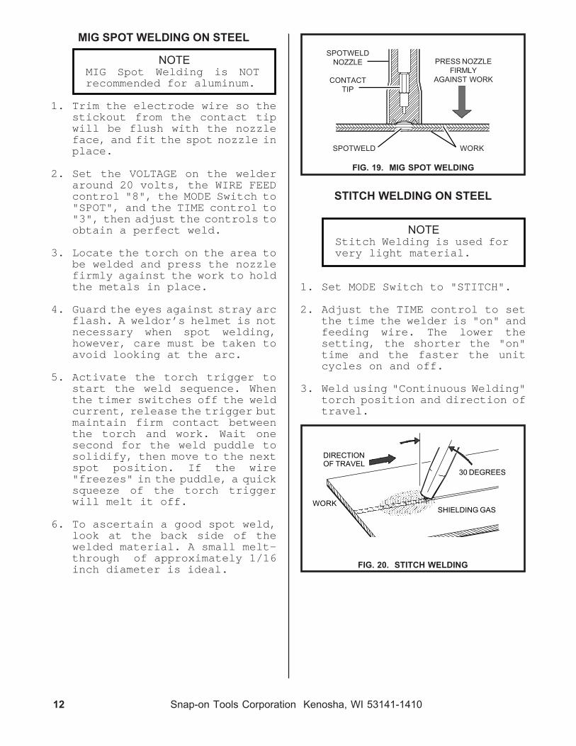
MIG SPOT WELDING ON STEEL
NOTEMIG Spot Welding is NOTrecommended for aluminum.
1. Trim the electrode wire so thestickout from the contact tipwill be flush with the nozzleface, and fit the spot nozzle inplace.
2. Set the VOLTAGE on the welderaround 20 volts, the WIRE FEEDcontrol "8", the MODE Switch to"SPOT", and the TIME control to"3", then adjust the controls toobtain a perfect weld.
3. Locate the torch on the area tobe welded and press the nozzlefirmly against the work to holdthe metals in place.
4. Guard the eyes against stray arcflash. A weldor’s helmet is notnecessary when spot welding,however, care must be taken toavoid looking at the arc.
5. Activate the torch trigger tostart the weld sequence. Whenthe timer switches off the weldcurrent, release the trigger butmaintain firm contact betweenthe torch and work. Wait onesecond for the weld puddle tosolidify, then move to the nextspot position. If the wire"freezes" in the puddle, a quicksqueeze of the torch triggerwill melt it off.
6. To ascertain a good spot weld,look at the back side of thewelded material. A small melt-through of approximately 1/16inch diameter is ideal.
FIG. 19. MIG SPOT WELDING
SPOTWELD WORK
PRESS NOZZLEFIRMLY
AGAINST WORK
SPOTWELDNOZZLE
CONTACTTIP
STITCH WELDING ON STEEL
NOTEStitch Welding is used forvery light material.
1. Set MODE Switch to "STITCH".
2. Adjust the TIME control to setthe time the welder is "on" andfeeding wire. The lower thesetting, the shorter the "on"time and the faster the unitcycles on and off.
3. Weld using "Continuous Welding"torch position and direction oftravel.
FIG. 20. STITCH WELDING
DIRECTIONOF TRAVEL
30 DEGREES
WORKSHIELDING GAS

Snap-on Tools Corporation Kenosha, WI 53141-1410 13
NOTEDO NOT use any anti-spatterspray when welding aluminum orstainless steel.
Restricted gas flow, holding thetorch too far from the work piece,and the use of CO2 gas rather than75% Argon - 25% CO2 will increasethe spatter levels.
MAINTENANCETo ensure that this equipment
maintains its operating effi-ciency, the following maintenanceschedule and procedures are recom-mended. These routines should beperformed regularly by the opera-tor.
REGULARLY - Usage and shop condi-tions determine frequency.
1. Remove and clean the torchnozzle and contact tip. The useof anti-spatter compound willreduce the adherence of spatterand makes its removal easier.
2. Blow out the torch liner prior tothe installation of each newspool of wire. The contact tipand gas diffuser must be re-moved, but it is not necessary toremove the liner.
3. If the torch cable assembly isbent severely, a kink may de-velop in the steel liner. Thiscan cause wire feeding problemsso a new liner should be in-stalled.
WEEKLY
1. Remove dirt and dust from thewire feed compartment. Use lowpressure dry compressed air.
OPERATING HINTS
BURN BACK
In the event the welding wireburns back into the contact tip:
1. Remove the nozzle from thetorch.
2. Unscrew the contact tip from thegas diffuser using a pair ofpliers as the tip will be veryhot.
3. Free the wire from the contacttip and clean the end of the tipso the new wire will slidesmoothly through the hole. DONOT use a drill or reamer toclean the hole as they willenlarge it and cause an erraticarc. Replace the contact tip ifit is badly damaged.
4. Install the contact tip in thetorch and tighten it firmly withan appropriate wrench.
5. Reinstall the torch nozzle.
6. If the wire continues to burnback, check for erratic wirefeed, or speed up the wire byincreasing the WIRE SPEED con-trol setting or reducing theVOLTAGE control setting.
SPATTER
Before beginning to weld andperiodically during welding, thetorch nozzle must be removed and thespatter (small globules of meltedmetal) cleared from the inside ofthe nozzle and the outside of thecontact tip and the gas diffuser.Spatter buildup between the contacttip and the nozzle can cause a shortcircuit and consequently, failureof the torch or welding machine.The frequent use of anti-spatterspray will help prevent the adher-ence of spatter to the torch compo-nents. (continued on following page)

14 Snap-on Tools Corporation Kenosha, WI 53141-1410
In the event of the failure of anypart of this equipment, contactyour Snap-On Tools representativefor replacement parts and service.When ordering parts from Snap-OnTools Corporation, order numbersshould be preceded by "CKS".
WARNINGDO NOT lift the unit when a gascylinder is installed or at-tached.
DO NOT weld on any item thathas a common electricalground.
DO NOT operate the unit withthe side panels removed.Overheating will occur.
DO NOT weld upon the case ofthe welding machine.
ONLY a qualified electricianshould perform work inside thewelding machine.
ALWAYS wear protective cloth-ing, leather gloves and a fullcover welding hood while weld-ing.
DO NOT weld in a closed inarea. Proper ventilation is anecessity, or a fresh airsupplied hood should be worn.
WHEN welding near com-bustibles, a helper or"watcher" should stand by witha fire extinguisher or otherfire protective device.
NEVER weld on a closed vesselor one that has containedcombustibles.
IF IN DOUBT - DON’T DO IT!
BE SAFE - DON’T BE SORRY!
2. Remove dirt and metal depositsfrom the grooves in the feedroll. If the grooves are badlyworn, the feed roll should bereplaced. If the pressure rolldoes not turn freely, it shouldbe replaced.
3. Check all gas fittings forleaks. Tighten or repair asrequired.
EVERY SIX MONTHS
1. Disconnect the welder from itsmain power supply.
2. Remove the machine’s side pan-els.
3. Using low pressure dry com-pressed air, remove dust anddirt from all components.
4. Check for loose or frayed wir-ing. Particularly check weldingcurrent wire connections.
5. Replace torch liner if neces-sary.
RECOMMENDEDCUSTOMER SPARE PARTS
The Snap-on Tools MM250SL is amachine of proven design and relia-bility. Following is a list ofconsumable items recommended asspare parts for this unit.
contact tips ....... M3-T30, etc.gas nozzles ............. M3T-N50nozzle insulators ......... M3T-Bgas diffusers ............. M3T-Dsteel liner(.020-.030) .. M103L-Bsteel liner(.035-.045) .. M104L-N
MAINTENANCE (Cont.)

Snap-on Tools Corporation Kenosha, WI 53141-1410 15
TROUBLE SHOOTING (SYMBOL*)FOR TECH. SERVICE, CALL TOLL-FREE 1-800-232-9353
The Trouble Shooting Chart is a guide in identifying and correctingpossible troubles which may occur when operating this equipment.
FAULT POSSIBLE CAUSE REMEDY
(SYMBOL*) - USE THIS IDENTIFIER, ALONG WITH THE SCHEMATIC DIAGRAM FOUND IN THE SERVICEMANUAL, FOR TROUBLE-SHOOTING PURPOSES.
EQUIPMENT MALFUNCTION
No main power, MM250SL switch is "OFF".(CB1) Turn switch "on".fan does not Wall breaker is "tripped". Reset wall breaker.operate, "Open" circuit breaker Reset or replace"on" indicator on MM250SL. (CB1) breaker.light is off. Loose or broken connection Tighten or repair
in power input circuit. connection.
Main power on, MIG torch unplugged. Plug in MIG torch.torch Faulty trigger switch. (S1) Replace micro switch.trigger Fault in torch cable. Check torch cableactivated, for continuity.no response. Loose or broken connection Check or repair
on wiring harness. (PLG2) connections.Wire feed motor unplugged. Plug in motor.
(RC5)Faulty control transformer. Check for 28VAC output.
(T2)Loose spot timer circuit Install properly.
board. (PC2)Defective spot timer Replace board.
circuit board. (CR2)(PC2)
Main power on, Pressure roll arm unlatched. Latch arm & add tension.torch "Slippage" at drive rolls. Increase drive rolltrigger tension. See page 8.activated, Wire path restricted. Clean path or replaceno wire feed torch liner.but contactor 5 amp mini breaker is Reset or replaceoperates & tripped. (CB2) breaker.gas flows. Wire feed circuit board Calibrate wire feed
needs calibrated. circuit board. Seepage 19.
Defective wire feed Replace circuit board.circuit board. (PC1)
Faulty wire feed motor Repair or replaceor connection. (M) faulty item.
Check motor on a12VDC battery.
Faulty motor relay. (CR1) Sand points or replacerelay.
Loose or broken connection. Tighten or repairconnection.
(continued on following page)

16 Snap-on Tools Corporation Kenosha, WI 53141-1410
FAULT POSSIBLE CAUSE REMEDY
TROUBLE SHOOTING (Cont.) (SYMBOL*)FOR TECH. SERVICE, CALL 1-800-232-9353
EQUIPMENT MALFUNCTION (Cont.)
Main power on, Loose torch thumb screw. Tighten thumb screw.torch Broken or loose connection. Check cables fortrigger continuity.activated, Repair or tightenno welding connections.current, but Unplugged or faulty power Plug in or replacegas flows & contactor switch. (W) switch.wire feeds. 208/230V selector wire off. Reattach wire.
(W)"Opened" thermal switch. Allow unit to cool, then
(TP1) retry.Faulty diodes. Check diodes. See page
18.
Main power on, No shielding gas Replace tank.torch - tank empty.trigger Loose or broken Tighten or repairactivated, connections. connections.no gas flow, Faulty Gas solenoid Repair or replacebut contactor valve. (GS) valve.operates & Clogged gas flow path. Locate & clean clog.wire feeds. Loose spot timer circuit Install properly.
board. (PC2)Defective spot timer Replace board.
circuit board. (CR2)(PC2)
FAULTY WELDS
"Jerky" or Worn , kinked or dirty torch Clean or replace"slipping" liner. liner.wire feed. Wire spool turns too Lubricate spool shaft.
hard.Worn double v-groove drive Replace drive roll.
roll.Weak pressure roll spring. Replace spring.Worn or dirty contact tip. Replace contact tip.Worn inlet guide(s). Clean or replace guides.Sticking pressure roll. Replace pressure roll.Feed roll tension incorrect. Adjust feed roll ten-
sion. See page 8.
Snap-on Tools Corporation Kenosha, WI 53141-1410 17
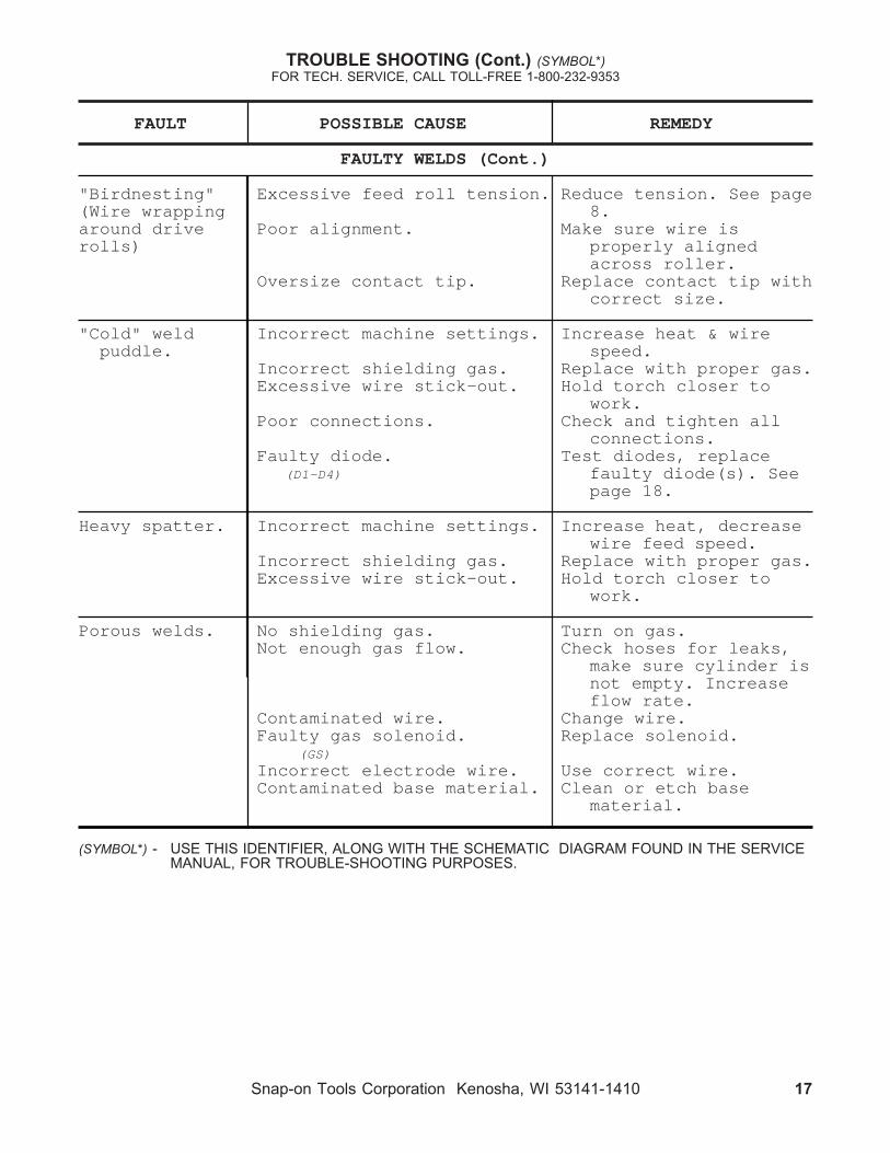
TROUBLE SHOOTING (Cont.) (SYMBOL*)FOR TECH. SERVICE, CALL TOLL-FREE 1-800-232-9353
(SYMBOL*) - USE THIS IDENTIFIER, ALONG WITH THE SCHEMATIC DIAGRAM FOUND IN THE SERVICEMANUAL, FOR TROUBLE-SHOOTING PURPOSES.
FAULT POSSIBLE CAUSE REMEDY
FAULTY WELDS (Cont.)
"Birdnesting" Excessive feed roll tension. Reduce tension. See page(Wire wrapping 8.around drive Poor alignment. Make sure wire isrolls) properly aligned
across roller.Oversize contact tip. Replace contact tip with
correct size.
"Cold" weld Incorrect machine settings. Increase heat & wirepuddle. speed.
Incorrect shielding gas. Replace with proper gas.Excessive wire stick-out. Hold torch closer to
work.Poor connections. Check and tighten all
connections.Faulty diode. Test diodes, replace
(D1-D4) faulty diode(s). Seepage 18.
Heavy spatter. Incorrect machine settings. Increase heat, decreasewire feed speed.
Incorrect shielding gas. Replace with proper gas.Excessive wire stick-out. Hold torch closer to
work.
Porous welds. No shielding gas. Turn on gas.Not enough gas flow. Check hoses for leaks,
make sure cylinder isnot empty. Increaseflow rate.
Contaminated wire. Change wire.Faulty gas solenoid. Replace solenoid.
(GS)Incorrect electrode wire. Use correct wire.Contaminated base material. Clean or etch base
material.

18 Snap-on Tools Corporation Kenosha, WI 53141-1410
12 VOLTBAT-TERY
DIODE
12 VOLTLIGHT BULB
12 VOLTBAT-TERY
12 VOLTLIGHT BULB
DIODE
+ -
+ -
TESTING AND REPLACING DIODES
Silicon diodes have proven to behighly reliable. However, weldspatter build-up in the torch canshort out and cause diode overloadand consequent failure. The follow-ing information is provided as aguide should a failure be sus-pected.
Silicon diodes exhibit two mainfault conditions:
1. "Open Circuit" - causes a reduc-tion in welder output.
2. "Short Circuit" - causes thecircuit breaker to trip.
If a fault is suspected, the diodemay be tested as follows:
1. Remove the top connection ofeach diode to be tested.
2. Using a Volt-Ohm Meter set onRX1K, check for continuitythrough the diode in both direc-tions. If there is no continuityin either direction, the diodeis in "open circuit" conditionand must be replaced. If thereis continuity in both direc-tions, the diode is in "shortcircuit" condition and must bereplaced. If there is continu-ity in one direction only, thediode is functioning properly.
FIG. 21. DIODE LOAD CHECK CONNECTION DIAGRAM - TEST FOR FLOW IN BOTH
DIRECTIONS
3. If all the diodes check outsatisfactorily with the Volt-Ohm Meter, a load check must bemade. This is easily accom-plished using a twelve voltbattery and a twelve volt lightbulb connected as shown. Againtest for electrical current flowin both directions. The bulbshould light in one (1) direc-tion only - not both.
CAUTIONNEVER use a "megger" or ahigh voltage device to testa diode.
4. When replacing diodes, it isvery important that a heat con-ductive compound (Radio Shack#276-1372) be used where thediode makes contact with thealuminum heat sink. Do notgrease the threads on the diode.

Snap-on Tools Corporation Kenosha, WI 53141-1410 19
WIRE FEED CALIBRATION
Due to INPUT LINE VOLTAGE varia-tions supplied to the welding ma-chine. The WIRE FEED SPEED should bechecked for proper operation.
TO CHECK
1. Remove any tension on the driveroll.
2. Turn the wire speed dial (on thefront of the machine) to "0".
3. Activate the torch trigger.
4. The bottom drive roll shouldrotate very slowly(non-jerky).
5. If this proves to be true, noadjustment is required.
IF ADJUSTMENT IS REQUIRED
1. Remove the top cover assemblyfrom the base unit.
2. Locate the printed circuitboards.
3. Referring to Figure 22, locatethe trim resistor, this is lo-cated in the upper right handcorner of the wire feed PC board.
4. Turn the wire speed dial (on thefront of the machine) to "0".
5. Remove any tension on the driveroll.
6. Activate the torch trigger.
7. Rotate the trim resistor, backand forth, until the bottomdrive roll moves.
8. Calibrate so the bottom driveroll rotates very slowly (non-jerky).
9. If calibrated correctly the wirespeed dial (on the front of themachine) should affect the speedof the drive roll from "0" thru"10".
10.Adjustment is now complete!
FIGURE 22. WIRE FEED PC BOARD
TRIMRESISTOR

20 Snap-on Tools Corporation Kenosha, WI 53141-1410
1. Unplug the feeder control cableplug from the control receptacle(OUTPUT)on the welder.
2. Unplug the feeder gas-currentcable/power plug and the workcable from the welders frontpanel.
3. Plug the FLEXTIG torch powercable into the negative (-) weldterminal and plug the work cableinto the positive (+) weld ter-minal. This provides straightpolarity current as required forTIG welding.
4. Plug the FLEXTIG torch switchcord into the welder controlreceptacle (OUTPUT).
5. Attach the FLEXTIG torch gashose directly to the gas regula-tor/flowmeter and adjust theflow to 20 C.F.H.
NOTEPure Argon is the shieldinggas to be used for TIGwelding.
6. Follow the operating instruc-tions in the F L E X T I G m a n u a l(Form WC5229).
7. To change back to standard MIGoperation, reverse the proce-dure.
CONNECTING THE FLEXTIG
CHANGING FROM STANDARD MIG OPERA-TION TO FLEXTIG OPERATION
CHANGING FROM STANDARD MIG OPERA-TION TO SPOOL GUN OPERATION
1. Unplug the feeder control cableplug from the control receptacle(OUTPUT) of the welder.
2. Plug the MHG5-B spool gun con-trol cable plug into the weldercontrol receptacle (OUTPUT).
3. Remove the feeder gas-currentcable/power plug from the weld-ers positive (+) weld terminal.
4. Plug the MHG5-B gun cable fit-ting into the welder positive(+) weld terminal.
NOTEMake sure the welder pri-mary gas hose and regula-tor/flowmeter are con-nected to a cylinder of theproper shielding gas - 100%Argon for aluminum and 98%Argon + 2% O2 for stainlesssteel and 75% Argon + 25%CO2 for steel welding.
5. Follow the operating instruc-tions in the MHG5-B manual (FormWC5268).
6. To change back to standard MIGoperation, reverse the proce-dure.
CONNECTING THE MHG5-BSPOOL GUN

Snap-on Tools Corporation Kenosha, WI 53141-1410 21
M.I.G. TORCH LINER INSTALLATION(steel only)
The MIG torch liner provided withthe MM250SL is designed for wirediameters from .035 thru .045. Ifsmaller wire diameters are to befed and or there is a problem (i.e.clog, kink, etc.), a liner change isrequired.
Following is a step by step guideto aid in liner removal and instal-lation.
NOTEWhen removing the welding wirefrom the MIG torch, careshould be taken to avoid thewire from uncoiling from thewire spool.
3/4"
LINERSTICKOUT
GAS SEAL
SET SCREW3/4"
CONNECTORPLUG
1 1/4+"
PROTRUDINGLINER
NECKASSEMBLY
REMOVING OLD LINER
Remove torch assembly from thewelding machine.
Place torch assembly on a flatsurface, making sure torch islaying straight as possible.
Remove nozzle, bushing insula-tor, contact tip and gas dif-fuser from the front end of thetorch assembly.
Loosen set screw located on theconnector end of the torch as-sembly (see FIG. 24).
Grip the liner and gas sealfirmly, then pull. The linershould easily slide from torchassembly.
1.
2.
3.
4.
5.
4.
5.
Install the new liner into theMIG torch assembly, until gasseal seats flush with the con-nector plug.
Tighten set screw. (Do not over-tighten), refer to FIG. 24.
6.
7.
Following the diagram in FIG.25, measure out 1 1/4"+ from theneck assembly and cut off theprotruding liner.
Debur the cutoff end of the linerto insure unobstructed wire feed.
8.
9.
10.
Install the gas diffuser andcontact tip of proper wire size,tighten with a wrench.
Install the bushing insulatoronto the gas diffuser. Spray the"O" rings with anti-spatter com-pound for lubrication.
Install the TWIST-ON adjustablenozzle and twist the nozzleduring the installation. Turn toPage 7 for correct nozzle ad-justment.
Remove the new liner from thepackage.
Uncoil liner and lay the linerparallel next to the MIG torchassembly.
Adjust the liner stickout lengthto 3/4" as shown in FIG. 23.
1.
2.
3.
INSTALLING NEW LINER
FIG. 23. - LINER STICKOUT
FIG. 24. - TORCH CONNECTOR END
FIG. 25. - TORCH FRONT END
22 Snap-on Tools Corporation Kenosha, WI 53141-1410
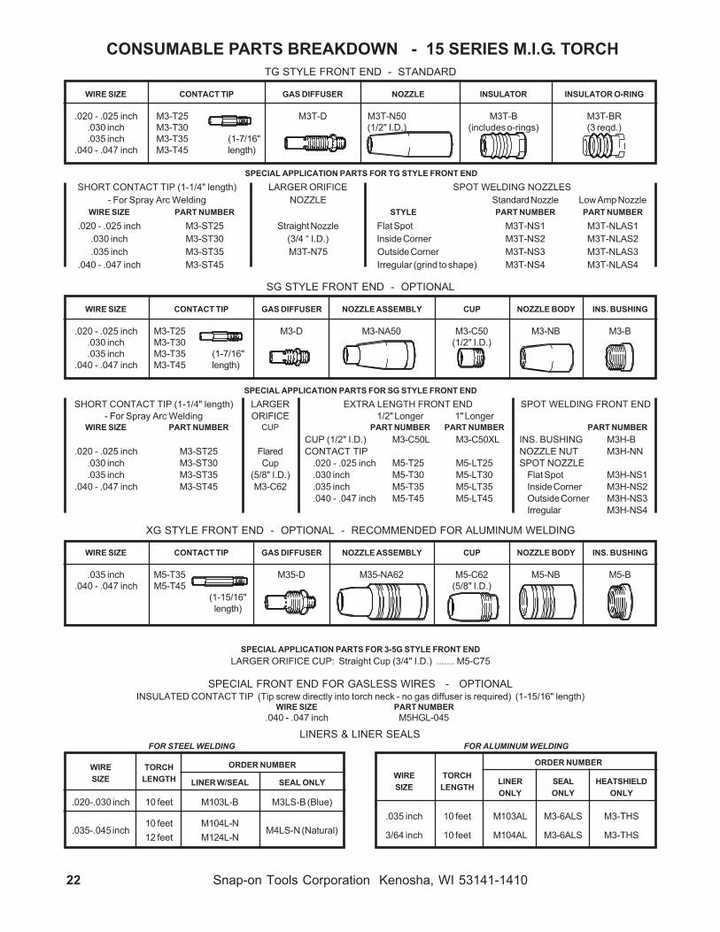
SG STYLE FRONT END - OPTIONAL
WIRE SIZE CONTACT TIP GAS DIFFUSER NOZZLE ASSEMBLY CUP NOZZLE BODY INS. BUSHING
.020 - .025 inch M3-T25 M3-D M3-NA50 M3-C50 M3-NB M3-B.030 inch M3-T30 (1/2" I.D.).035 inch M3-T35 (1-7/16"
.040 - .047 inch M3-T45 length)
CONSUMABLE PARTS BREAKDOWN - 15 SERIES M.I.G. TORCHTG STYLE FRONT END - STANDARD
WIRE SIZE CONTACT TIP GAS DIFFUSER NOZZLE INSULATOR INSULATOR O-RING
.020 - .025 inch M3-T25 M3T-D M3T-N50 M3T-B M3T-BR.030 inch M3-T30 (1/2" I.D.) (includes o-rings) (3 reqd.).035 inch M3-T35 (1-7/16"
.040 - .047 inch M3-T45 length)
SPECIAL APPLICATION PARTS FOR TG STYLE FRONT ENDSHORT CONTACT TIP (1-1/4" length) LARGER ORIFICE SPOT WELDING NOZZLES
- For Spray Arc Welding NOZZLE Standard Nozzle Low Amp NozzleWIRE SIZE PART NUMBER STYLE PART NUMBER PART NUMBER
.020 - .025 inch M3-ST25 Straight Nozzle Flat Spot M3T-NS1 M3T-NLAS1.030 inch M3-ST30 (3/4 “ I.D.) Inside Corner M3T-NS2 M3T-NLAS2.035 inch M3-ST35 M3T-N75 Outside Corner M3T-NS3 M3T-NLAS3
.040 - .047 inch M3-ST45 Irregular (grind to shape) M3T-NS4 M3T-NLAS4
SPECIAL APPLICATION PARTS FOR SG STYLE FRONT ENDSHORT CONTACT TIP (1-1/4" length) LARGER EXTRA LENGTH FRONT END SPOT WELDING FRONT END
- For Spray Arc Welding ORIFICE 1/2" Longer 1" LongerWIRE SIZE PART NUMBER CUP PART NUMBER PART NUMBER PART NUMBER
CUP (1/2" I.D.) M3-C50L M3-C50XL INS. BUSHING M3H-B.020 - .025 inch M3-ST25 Flared CONTACT TIP NOZZLE NUT M3H-NN
.030 inch M3-ST30 Cup .020 - .025 inch M5-T25 M5-LT25 SPOT NOZZLE
.035 inch M3-ST35 (5/8" I.D.) .030 inch M5-T30 M5-LT30 Flat Spot M3H-NS1.040 - .047 inch M3-ST45 M3-C62 .035 inch M5-T35 M5-LT35 Inside Corner M3H-NS2
.040 - .047 inch M5-T45 M5-LT45 Outside Corner M3H-NS3Irregular M3H-NS4
FOR STEEL WELDING
ORDER NUMBERWIRE TORCHSIZE LENGTH LINER W/SEAL SEAL ONLY
.020-.030 inch 10 feet M103L-B M3LS-B (Blue)
10 feet M104L-N.035-.045 inch M4LS-N (Natural)
12 feet M124L-N
FOR ALUMINUM WELDING
ORDER NUMBERWIRE TORCH
LINER SEAL HEATSHIELDSIZE LENGTH
ONLY ONLY ONLY
.035 inch 10 feet M103AL M3-6ALS M3-THS
3/64 inch 10 feet M104AL M3-6ALS M3-THS
XG STYLE FRONT END - OPTIONAL - RECOMMENDED FOR ALUMINUM WELDING
WIRE SIZE CONTACT TIP GAS DIFFUSER NOZZLE ASSEMBLY CUP NOZZLE BODY INS. BUSHING
.035 inch M5-T35 M35-D M35-NA62 M5-C62 M5-NB M5-B.040 - .047 inch M5-T45 (5/8" I.D.)
(1-15/16"length)
SPECIAL APPLICATION PARTS FOR 3-5G STYLE FRONT ENDLARGER ORIFICE CUP: Straight Cup (3/4" I.D.) ....... M5-C75
SPECIAL FRONT END FOR GASLESS WIRES - OPTIONALINSULATED CONTACT TIP (Tip screw directly into torch neck - no gas diffuser is required) (1-15/16" length)
WIRE SIZE PART NUMBER.040 - .047 inch M5HGL-045
LINERS & LINER SEALS

Snap-on Tools Corporation Kenosha, WI 53141-1410 23
PARTS BREAKDOWN - 15 SERIES MIG TORCH (Cont.)
M3-402 M3-402
M1-401
TORCH NECK GROUP
M3-112M3-119 M3-120*
M3-101B*
M3-405M3-200B ASSEMBLY (2 REQD.)
M3-201BM3-203
(2 REQD.)M3-214
M3-202 M3-211
M3-212 M3-213
M3-407
QUICK CONNECTOR GROUP
M3-406M3-309 (2 REQD.)(2 REQD.)
M3-307
M3-301A M3-305A*
M3-308 M3-306 M3-120*(2 REQD.)
M3-310A
PART NO. DESCRIPTION (SYMBOL)TORCH NECK GROUP
M3-101B ..... TORCH NECK *M3-112 ....... NECK INSULATORM3-119 ....... LOCK SCREW - SWITCH HOUSINGM3-120 ....... FERRULE *
M3-200B ..... SWITCH ASSEMBLYCONSISTING OF:
M3-201B ..... SWITCH HOUSINGM3-202 ....... SWITCH (S1)M3-203 ....... SWITCH SCREW (2 REQUIRED)M3-211 ....... TRIGGER - WITH ADJUSTING SCREWM3-212 ....... TRIGGER ADJUSTING SCREW (ONLY)M3-213 ....... TRIGGER PINM3-214 ....... TRIGGER SPRING
QUICK CONNECTOR GROUPM3-120 ....... FERRULE *M3-301A ..... CONNECTOR HOUSINGM3-305A ..... CONNECTOR STEM *M3-306 ....... CONNECTOR PLUG
- WITH SETSCREW & O-RINGSM3-307 ....... SETSCREW (ONLY)M3-308 ....... O-RING (ONLY) (2 REQUIRED)M3-309 ....... TERMINAL - CONNECTOR CONTACT
(2 REQUIRED)M3-310A ..... BOOT / CABLE SUPPORT
M1-401 ....... HANDLEM3-402 ....... HANDLE SCREW (2 REQUIRED)M3-405 ....... TERMINAL - TORCH END
(2 REQUIRED)M3-406 ....... TERMINAL - CONNECTOR END
(2 REQUIRED)M3-407 ....... HANGING BRACKET
M1510CBL... 10 FOOT CABLE *M1512CBL... 12 FOOT CABLE *
M1510CBL*M1512CBL*
NOTES:
* BECAUSE SPECIAL TOOLSAND PROCEDURES AREREQUIRED TO PROPERLYINSTALL THE CABLE ONTHE TORCH NECK ANDTHE CONNECTOR STEM,ITEMS WITH THE ASTERICKARE AVAILABLE FACTORYINSTALLED ONLY.
TORCH REBUILD PROGRAM15 SERIES TORCHES CANBE REBUILT BY THEFACTORY FOR A NOMINALLABOR + PARTS CHARGE.

24 Snap-on Tools Corporation Kenosha, WI 53141-1410
MHG5-B SYSTEM COMPONENTS1 each MHG-5 Spool Gun (only)
1 each HGC9-25 Hand Gun Cable Assemblywith fittings - 25 feet length
7 each MG-TXX Contact Tip(1 installed in gun)
2 - .030 (MG-T30)
3 - .035 (MG-T35)
2 - 3/64 (MG-T364)
1 each M35-NA62 Nozzle Assembly(installed on gun)
1 each M35-D Gas Diffuser(installed on gun)
OPTIONSFLEXTIG
TIG WELD WITH YOURSNAP-ON TOOLS MUSCLE MIG SYSTEM
(MM140SL, MM250SL)
The TIG Welding Process is used to produce the highest quality, porosity-freewelds. The FLEXTIG adds TIG Welding capabilities to your Snap-on Tools MIGWelder.
The FLEXTIG is designed for Tungsten-Inert Gas (TIG) welding with DirectCurrent, Straight Polarity (DCSP) on steel, stainless steel, chrome-moly, copperor cast iron (18 Ga. minimum plate thickness).
THE FLEXTIG WILL NOT WELD ALUMINUM.The FLEXTIG consists of a 200 amp, gas cooled torch with built-in gas controlvalve and remote on-off switch, 12-1/2 or 25 foot cable assembly and accessoriesrequired for putting the unit in service.
SPECIFICATIONSPart Number ........................ FLEXTIG 12 (12-1/2' cable)
FLEXTIG 25 (25' cable)
Torch Rating ....................... 200 Amps, DCSP
Duty Cycle ........................... 100% (reduce duty cycle whenoperating over 200 amps.)
Cooling Method ................... Gas(100% ARGON)
Shielding GasControl Method ............... Gas Valve on Torch
Welding CurrentOn-Off Control ................ Locking Switch onTorch
MHG5-BONE POUND SPOOL GUN
FOR ALUMINUM MIG WELDINGWITH SNAP-ON TOOLSMUSCLE MIG SYSTEMS
(MM140SL, MM250SL)
The MHG5-B (Motorized Hand Gun System) is a compact, light-in-weight,easy to operate MIG welding system designed for aluminum welding. It willfeed .023" Thru 3/64" diameter wire from 4 inch spools. The standardequipment cable is 25 feet in length. 35 foot and 50 foot cables are optional.The wire speed control knob is built into the gun handle.
With the following options, the MHG5-B can also be used to weld steel orstainless steel (.030"-.035" diameter wire size).
SN-2160K Knurled Drive Roll for .030 - .035" steel wireM5-T30 Contact tip - for .030" steel wire
or M5-T35 Contact tip - for .035" steel wire
SPECIFICATIONS
Part Number ....................... MHG5-B
Gun Rating ......................... 200 Amps @ 100% duty cycle250 Amps @ 60% duty cycle
Wire Feed Speed Range ... 50 to 650 inches per minute
Cooling Method .................. Air (gas)
CONTENTS OF FLEXTIG1 each TIG Torch with built-in valve1 each Locking Electric Switch with cord & plug
(installed on torch)1 each 12-1/2 foot Power Cable with Connector
(installed on torch)1 each 15 foot Gas Hose with fitting
(installed on torch)3 each 3C116 Collet - for 1/16" tungsten3 each 3C332 Collet - for 3/32" tungsten2 each 3CB116 Collet Body - for 1/16" tungsten2 each 3CB332 Collet Body - for 3/32" tungsten2 each 3C6 Gas Cup - 3/8" orifice6 each 3C7 Gas Cup - 7/16" orifice2 each 3C8 Gas Cup - 1/2" orifice1 each 300L Long Backcap3 each 1/16" X 3" Tungsten Electrode3 each 3/32" X 3" Tungsten Electrode
Snap-on Tools Corporation Kenosha, WI 53141-1410 25
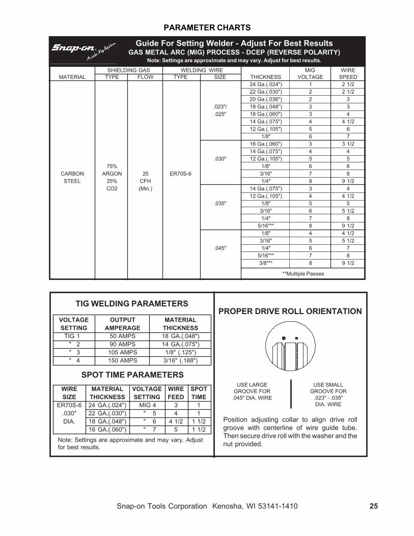
PARAMETER CHARTS
SHIELDING GAS WELDING WIRE MIG WIREMATERIAL TYPE FLOW TYPE SIZE THICKNESS VOLTAGE SPEED
24 Ga.(.024") 1 2 1/222 Ga.(.030") 2 2 1/220 Ga.(.036") 2 3
.023"/ 18 Ga.(.048") 3 3.025" 16 Ga.(.060") 3 4
14 Ga.(.075") 4 4 1/212 Ga.(.105") 5 6
1/8" 6 716 Ga.(.060") 3 3 1/214 Ga.(.075") 4 4
.030" 12 Ga.(.105") 5 575% 1/8" 6 6
CARBON ARGON 25 ER70S-6 3/16" 7 8STEEL 25% CFH 1/4" 8 9 1/2
CO2 (Min.) 14 Ga.(.075") 3 412 Ga.(.105") 4 4 1/2
.035" 1/8" 5 53/16" 6 5 1/21/4" 7 8
5/16"** 8 9 1/21/8" 4 4 1/23/16" 5 5 1/2
.045" 1/4" 6 75/16"** 7 83/8"** 8 9 1/2
Guide For Setting Welder - Adjust For Best ResultsGAS METAL ARC (MIG) PROCESS - DCEP (REVERSE POLARITY)
Note: Settings are approximate and may vary. Adjust for best results.
**Multiple Passes
PROPER DRIVE ROLL ORIENTATION
USE LARGE USE SMALLGROOVE FOR GROOVE FOR
.045" DIA. WIRE .023" - .035"DIA. WIRE
Position adjusting collar to align drive rollgroove with centerline of wire guide tube.Then secure drive roll with the washer and thenut provided.Note: Settings are approximate and may vary. Adjust
for best results.
SPOT TIME PARAMETERS
TIG WELDING PARAMETERS
WIRE MATERIAL VOLTAGE WIRE SPOTSIZE THICKNESS SETTING FEED TIME
ER70S-6 24 GA.(.024") MIG 4 3 1.030" 22 GA.(.030") " 5 4 1DIA. 18 GA.(.048") " 6 4 1/2 1 1/2
16 GA.(.060") " 7 5 1 1/2
VOLTAGE OUTPUT MATERIALSETTING AMPERAGE THICKNESS
TIG 1 50 AMPS 18 GA.(.048")" 2 90 AMPS 14 GA.(.075")" 3 105 AMPS 1/8" (.125")" 4 150 AMPS 3/16" (.188")

Snap-on Tools Corporation Kenosha, WI 53141-1410