owner's manual - managemylife.commanagemylife.com/mmh/lis_pdf/ownm/l0712470.pdfsnow thrower...
TRANSCRIPT
"MPORTANT MANUAL
OWNER'SMANUAL
MODEL NO.536.886531
Caution:Read and FollowAll Safety Rulesand InstructionsBefore OperatingThis Equipment
DO NOT THROW AWAY
5 HORSEPOWER22" DUAL STAGESNOW THROWEROptional electric start
®
• Assembly• Operation• Customer Responsibilities° Servlc_ and Adjustments• Repair Parts
,,=,=,,=,,= ,=,
SEARS, ROEBUCK AND CO., Hoffman Estates, IL 60195 U.S.A.= 11 11 11 ,=H ,,,,HH= ,H 111 11,11,1 =,==,=H= 11 1111

SAFETY RULES
_ CAUTION. ALWAYS DISCONNECT SPARK PLUG WIRE AND _liPLACE WIRE WHERE IT CANNOT CONTACT SPARK PLUGTQ PREVENT ACCIDENTAL STARTING WHEN SETTING-UP,TRANSPORTING, ADJUSTING OR MAKING REPAIRS,
IMPORTANTSAFETY STANDARDS REQUIRE OPERATOR PRESENCE CONTROLS TO MINIMIZE THERISK OF INJURY. YOUR SNOW THROWER IS EQUIPPED WITH SUCH CONTROLS. DO NOTATTEMPT TO DEFEAT THE FUNCTION OF THE OPERATOR PRESENCE CONTROL UNDERANY CIRCUMSTANCES.
TRAINING
1. Read the operator's manual carefully. Bethoroughly familiar with the controls and theproper use of the snow thrower. Know how tostop the snow thrower and disengage thecontrols quickly.
2. Never allow children to operate the snow throwerand keep them away while it is operating. Neverallow adults to operate the snow th rower withoutproper instruction. Do not carry passengers.
3. Keep the area of operation clear of all persons,particularly small children, and pets_
4. Exercise caution to avoid slipping or falling,especially when operating in reverse.
PREPARATION
1. Thoroughly inspect the area where the snowthrower is to be used and remove all doormats,sleds, boards, wires, and other foreign objects.
2. Disengage all clutches and shift into neutralbefore starting the engine (motor).
3. Do not operate the snow thrower without wearingadequate winter outer garments° Wear footwearthat will improve footing on slippery surfaces,
4, Handle fuel with care; it is highly flammable.
(a) Use an approved fuel container.
(b) Never remove fuel tank cap or add fuel to arunning engine or hot engine.
(c) Fill fuel tank outdoors with extreme care.Never fill fuel tank indoors.
,
(d) Replace fuel tank cap securely and wipe upspilled fuel.
(e) Never store fuel or snow thrower with fuel inthetank insideof abuilding where fumes mayreach an open flame or spark.
(f) Check fuel supply before each use, allowingspace for expansion as the heat of the engine(motor) and/or sun can cause fuelto expand.
Use extension cords and receptacles as specifiedby the manufacturer for all snow throwers withelectric drive motors or electric starting motors
6_ Adjust the snow thrower height to clear gravel orcrushed rock surfaces.
7o Never attempt to make any adjustments while theengine (motor) is running (except whenspecifically recommended by the manufacturer).
8, Let engine (motor) and snow thrower adjust tooutdoor temperatures before starting to clearsnow.
9. Always wear safety glasses or eye shields duringoperation or while performing an adjustment orrepair to protect eyes from foreign objects thatmay be thrown from the snow thrower.
OPERATION
1. Do not put hands or feet near or under rotatingparts° Keep clear of the discharge opening at alltimes,,
2. Exercise extreme caution when operating on orcrossing gravel drives, walks, or roads. Stay alertfor hidden hazards or traffic.
3. After striking a foreign object, stop the engine(motor), remove the wire from the spark plug,disconnect the cord on electric motors,thoroughly inspect the snow thrower for anydamage, and repair the damage before restartingand operating the snow thrower.
4, If the snow thrower should start to vibrateabnormally, stop the (motor) and checkimmediately forthe cause_ Vibration is generallya warning of trouble°
5. Stop the engine (motor) whenever you leave theoperating position, before unclogging the auger/impeller housing or discharge guide, and whenmaking any repairs, adjustments, or inspections.
When cleaning, repairing, or inspecting, makecertain the auger/impeller and all moving partshave stopped. Disconnect the spark plug wireand keep the wire away from the plug to preventaccidental starting°
7 Take all possible precautions when leaving thesnow thrower unattended. Disengage the auger/impeller, shift to neutral, stop engine, andremove key.

SAFETY RULES
8. Do not run the engine indoors, except when startingthe engine and for transporting the snow thrower inor out of the building. Open the outside doors;exhaust lumesaredangerous (containing CARBONMONOXIDE, an ODORLESS and DEADLY GAS).
9. Do not clear snow across the face of slopes.Exercise caution when changing direction onslopes. Do not attempt to clear steep slopes.
10. Never operate the snow thrower without properguards, plates or other safety protective devicesin place.
11. Never operate the snow thrower near glassenclosures, automobiles, window wells,drop-oils, and the like without properadjustmentof the snow discharge angle. Keep children andpets away.
12. Do not overload the machine capacity byattempting to clear snow at too fast a rate.
13o Never operate the snowthrower at high transportspeeds on slippery surfaces. Look behind anduse care when backing°
t4. Never direct discharge at bystanders or allowanyone in tront of the snow thrower.
15. Disengage power to the auger/impeller whensnow thrower is transported or not in use.
16. Useonly attachments and accessories approvedby the manufacturer of the snow thrower (suchas tire chains, electric start kits, etc.).
17. Never operate the snow thrower without goodvisibility or light. Always be sure of your footing,and keep a firm hold on the handles. Walk; neverrug.
CAUTION: STOP THEENGINE BEFORE
UNCLOGGING
%DISCHARGE CHUTE.Lj
MAINTENANCE AND STORAGE
1. Check shear bolts and other bolts at frequentimproper tightness to be sure the snow throweris in safe working condition.
2. Never store the snow throwerwith fuel inthe fueltank inside a building where ignition sources arepresent such as hot water and space heaters,clothes dryers, and the like. Allow the engine tocool before storing in any enclosure.
3. Always refer to operator's manual instructionsfor important details if the snow thrower isto bestored for an extended period°
4. Maintain or replace safety and instruction labels,as necessary.
5o Run the snow thrower a few minutes afterthrowing snow to prevent freeze-up of the auger/impelter_
WARNING ...................
This snow thrower is for use on sidewalks,driveways, and other ground level surfaces.
CAUTION should be exercised while using onsteep sloping surfaces. DO NOT USE SNOWTHROWER ON SURFACES ABOVE GROUNDLEVEL such as roofs of residences, garages,porches or other such structures or buildings,
.................. ,,, i Hl,ll,ll,,,
I _ LOOK FOR THIS SYMBOL TO POINT OUT
! A IMPORTANT SAFETY PRECAUTIONS. IT!,_ MEANS--ATTENTION!!! BECOMEALERT!!!
,..===., YOUR SAFETY IS INVOLVED.• ................................... i iiiii
,=

CONGRATULATIONS on your purchase of a SearsCraftsman Snow Thrower It has been designed, engi-neered and manufactured to give you tfTebest possibledependability and performanceShould you experience any problem you cannot easilyremedy, please contact your nearest Sears ServiceCenter/Department Sears has competent, well-trainedtechnicians and the proper tools to service or repair thisunitPtease read and retain this manual The instructions willenable you to assemble and maintain your snow throwerproperly, Always observe the "SAFETY RULES,"
H i iHl,, ,,Hn
MODELNUMBER 536 886531
SERIALNUMBERDATE OF'--_PURCHASE
THE MODELAND SERtAL NUMBERS WILL BEFOUND ON A DECAL ATTACHED TO THE REAROF THE SNOW THROWER HOUSING
YOU SHOULD RECORD BOTH SERIAL NUMBERAND DATE OF PURCHASE AND KEEP tN A SAFEPLACE FOR FUTURE REFERENCE
MAINTENANCE AGREEMENTA Sears Maintenance Agreement is available on thisproduct Contact your nearest Sears Store for details
PRODUCT SPECIFICATIONSu,,,, ,, i,iH ,,,, i, i , u, ,,H,,, , i,,,,H, ,,H,
HORSE POWER: 5 hp
DISPLACEMENT: 12.04cu. in.
GASOLINE CAPACITY: 2 quartsUnleaded
HH, IIII1,1 H I ,,,, ,.
OIL (21 oz. Capacity): SAE 5W-30
SPARK PLUG : Champion
(GAP .030 in.) RJ19LMHHn,HH H IHHH nil,,,
VALVE CLEARANCE: Intake: .010 In.Exhaust: .010 In_
i Hm,H,, I " I'
CUSTOMER RESPONSIBILITIES
• Read and observe the safety rules• Follow a regular schedule in maintaining, caring for and using your snow throwera FolIow the instructions under "Customer Responsibilities" and "Storage" sections of this owner's manual,,
HH, H,,' ......................... , HHH H',,' ! nHHH I H, HI HHHn" I,"l
TWO YEAR LIMITED WARRANTY ON CRAFTSMANSNOW THROWER
For two years from the date of purchase, when this Craftsman Snow Thrower is maintained, lubricatedand luned_up according to the instructions in the owner's manual, Sears will repair, free of charge, anydefect in material and workmanship
tf this Craftsman Snow Thrower is used for commercial or rental purposes, this warranty applies for only90 days from the date of purchase
This warranty does not cover the following:
* Expendable items which become worn during normal use, such as spark plugs, drive belts and shearpins
* Repairs necessary because of operator abuse or negligence, including bent crankshafts and the failureto maintain the equipment according to the instructions contained in the owner's manual
WARRANTY SERVICE IS AVAILABLE BY RETURNING THE CRAFTSMAN SNOW THROWER TO THENEAREST SEARS SERVICE CENTER/DEPARTMENT IN THE UNITED STATES TH1S WARRANTYAPPLIES ONLY WHILE THIS PRODUCT IS IN USE tN THE UNITED STATES
This warranty gives you specific legal rights, and you may also have other rights which may vary fromstate to state
SEARS, ROEBUCK AND CO Deparlment 731CR-W, Hoflman Estates, IL 60195........................................ , i,, HH I , HHH, HI H I
4
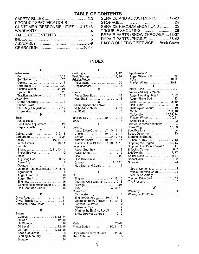
TABLE OF CONTENTSSAFETY RULES ................................................2,3PRODUCT SPECIFICATIONS ...............................4CUSTOMER RESPONSIBILITIES ......4,15,16WARRANTY ......................................................... 4TABLE OF CONTENTS .......................................5INDEX .........................................................................5ASSEMBLY .........................................................6-9OPERATION .................. ................................... t 0-14
SERVICE AND ADJUSTMENTS ........... 17-23STO RAG E ..............................................................24SERVICE RECOMMENDATIONS .....................25TROUBLE SHOOTING .................................... 26
REPAIR PARTS (SNOW TH ROWER)co. 28-37REPAIR PARTS (ENGINE) ................................38-42PARTS ORDERINGISERVlCE ........Back Cover
INDEX
AAdjustment:
Belt ...................................................18,19Bell Guide ...........................................20Cable ...........................................................18Carburetor ...........................................13,22Friction Wheel ....................................20,2t
Spark Plug .................................................23Traction and Auger .................... 18,19
Assembly:Crank Assembly ............................................ 8Shifter Lever ....................................................9Skid Height Adjustment ..................7, 17Unpacking ....................................... 7
BBelts:
Adjust Belts ........................ 18,19Belt Guide Adjustment ............ 20Replace Belts ............................... 19
CCables, Clutch ......................... 7, 9, 18Carburetor: ........................................13,24Choke ............................ 10, 11, 13Clutch, Levers ........................... 10, 11Controls:
Engine ............................ 10, 11, t3, t4Snow Thrower ............................ 10
Crank:
Adjusting Rod ...................... 8, 17Assembly ........................................... 8Operation ................................... 11
Customer Respo nsibilities .........4,15,16Agreement .................................. 4Auger Gear Box .................... 16Auger Shaft .................................. 15Engine ........................................ 16General Recommendations ........ 15Hex Shaft and Gears .................... 16
DDrive, Auger ............................. 11Drive, Traction ......................... 11Deflector, Snow Chute .................. 1t
EEngine:
Conlrol .......................... t0, 1t, 13, 14Oil Cap ....................... t2, 16Oil Change .......................... 16Oil Level ...................... 12, 16Oil Type .......................... 4, 12, 16Speed Governor ............... 24Starting, Manually ................. 13Storage .................................... 24
FFuel, Type ............................. 4, 12Fuel, Storage .......................................12, 24Friction Wheel:
Adjustment ........................................ 20Replacement ................................. 21
GGears:
Auger Gear Box ............................... 16Hex Shaft .............................................16
H
Handle, Upper and Lower ..........................7Height Adjust Skids ...............................7, 17Hex Shaft .........................................................t 6
iIgnition, Key .................. 10, 11,13, 14Index .......................... 5
LLevers:
Auger Drive Clutch ........7, 10, 11, 18Choke ...................... 10, 11,13, 14Shifter ................................... 9, 10, 11ThrOttle Control ........... 10, l 1,13, t 4Traction Drive Clutch .... 7, 10, 11, 18
Lubrication:Auger Gear Box .......................... 18Auger Shaft ................... 15Chart .................................... 25Disc Drive Plate ......................... 15
Engine ................................. t2,!6,24Flex Shaft and Gears ................ 16
OOi!:
Engine .....................................4, 12, 16Extreme Cold Weather .............. 12,16Storage ....................................... 24Type ....................... 4, I2, I6
Operation:Carburetor .................. 13Engine Controls .......... 10, 11, !3,14Operating 9now Thrower 11, 12, 15Lockout Pin, Wheel ................... 12Operating Tips ...................... 14Starting the Engine, Recoil ........ 13Snow Thrower Controls ......... 10-12
PParts .............................. 28-42Primer Bulton ........... 10, 1t, 13
R
Repair/Replacement Parts ...... 28-42Recoil Starter .......................... 13
Replacements:Auger Shear Boil ...............................22Belts ............................................. 18,19Friction Wheel ..............................20,21
S
Safety Rules .........................................2, 3Service and Adjustments:
Auger Housing Height .............. 7, 17Auger Shear Bolt ............................. 22Belts ........................................... 18-19Belt Guide ......................................... 20Belt Replacements .............................19Cable ...................................... 7, 9, 18Carburetor ............................ 13,22, 24Friction Wheel ................. 20, 2t
Spark Plug ................................... 23Service Recommendations ............ 24
Spark Plug ................................. 16, 23Specifications ......................... 4Speed Governor .......................... 22Starting the Engine:
Recoil Start ........................................ 13Stopping the Engine ................ 13, ! 4Stopping the Snow Thrower ............. 11Shipping Carton .............................. 6, 7Skid Height .................................. 17Shifter Lever ......................... 9-11Shear Bolts ....................... 22
Storage ................................ 24T
Table of Contents ......................... 5Trouble Shooting Chart .................... 26Tools for Assembly .......................... 6Traction Drive Belt ................. 18, I9Tire Pressure ..................... 17
W
Warranty ..................................... 4Wheel, Lockout Pin ........ !2

ASSE LY.,?,ONTENTS OF SHIPPING CARTON TOOLS REQUIRED FOR ASSEMBLY
- Snow thrower complelely assembled except for tthe crank assembly, smiter lever knob, and the 2upper handle, which is in the folded down position 2
- Parts Bag Containing: 2- Owner's Manual (Not Shown) and 1
Parts Shown Below: 1- Conlainer of 5W30 Oil 1
Kniie (to cut cadon and plastic ties)1/2 inch wrenches (or adjustable wrenches)9/16 inch wrenches (or adjustable wrenches)3/4 inch wrenches (or adjustable wrenches)Pliers (to spread cotter pin)ScrewdriverMeasuring Tape or Ruler
CONTENTS OF PARTS BAG
*2 - Spare Shear Bolts(1t4-20 x t-3/4 tn )
"2 - Spare 1t4-20 Lecknuts1 - Knob With Threads
"Non-Assembly Partsnn n,u,,, H,u m,,,,,, i, , i ,,,,,,,,,,iu ' , ,, ,i .
2 - ignition Keys
"2- Spare t14-20Sleeve Spacers

Figure1showsthesnowthrower inthe shipping position
Figure 2shows the snow thrower completely assembled
Reference to the right and left hand side of the snowthrower is from the operator's position at the handle.
TO REMOVE SNOW THROWER
FROM CARTON (See Fig. 1)
• Remove staples from the top of the carton
• Locate and remove container of 5W30 oil.
• Locatethe crank assembly and place the assemblyaside
o Remove and discard the packing material fromaround snow thrower
o Cut all four corners of the carton from top to bottomand lay the panels flat
= Remove the packing material fromthe control paneland upper handle assembly
• Rollthe snowthrower off the carton by pulling onthelower handle+
CAUTION: Do Not back over cables
® To complete upper handle instaltation and installchute crank assembly, see To Install The UpperHandle and Crank Assembty paragraph on page 8
ii iin,,
FIG. 1
CABLE
UPPERHANDLE
ASSEMBLY
NOTE: If the cables have become disconnected from lheclutch levers, reinstall the cabfes as shown in Fig, 3.
HOW TO SET UP YOUR SNOWTHROWER
Your snow thrower is equipped with height adjustskids (See Fig 2) on the outside ot the auger hous-ing. To adjust the skid height for different conditions,see To Adjust Skk:l Height paragraph on page 17+.
" CAUTION: IF' YO'U'"'ARE 'R'E'r_0VING
SNOW FROM ANY GRAVELED OR UJ_-
EVEN SURFACE, RAISETHE FRONTOFTHE SNOW TH ROWER BY MOVING THE
SKIDS DOWN+ THIS WILL HELP TO PREVENTSTONES AND OTHER DEBRIS FROM BEINGPICKED UP AND THROWN BY THE AUGER.
"Z" FITTING
FIG. 2
TRACTIONDRIVELEVER
7

ASSEMBLY,,,, ,,,, - ,, ,,,,, ,,,,
rO INSTALL THE UPPER HANDLE
AND CRANK ASSEMBLY
• Remove the screws, flatwashers, lockwashers, andhex nuts securing the shitter plate in the lower holesof the lower handle and move shift lever to 3rd gear
® Loosen, but do not remove, the screws, flatwashers,lockwashers, and hex nuts in _heupper holes ol thelower handle
® Raise upper handle into operating position Upperhandle should be to the outside of the lower handleand shifter prate to the inside
O Replacethe right hand screw, flatwasher, lockwasher,and hex nut through the handle and shifter plate Donot tighten t_ntilall bolts are in place
NOTE: Unless you have the assistance of another per-son, it may be easier to install one side ot the handle at atime.
@ Remove the 3/8" nylon locknut and flatwasher fromthe eye bolt assembly (on the chute crank assemblyearlier) Check to make sure the two 3/8" jam nuts aretight The jam nuts should be 2 75 inches from the endof the eye bolt (See Fig 4B)
@ Remove the plastic bag, the plastic cap, the cotter pinand the washer from the crank assembly and setaside (See Fig 5)
@ Rotate the notched section of the discharge chutetoward the crank-adjusting rod (See Fig 5)
® Install the wormed end of the crank through the hofein the adjusting rod and secure the end with thellatwasher and cotter pin, as shown in Fig 5
• Bend the ends of the cotter pin around the rod andreinstall the plastic cap
@ Instal] eye bolt through lower hole in the left hand sideot the handle and shifter plate (See Fig 4B)
® tnstall the 3/8" flatwasher and the 3/8" nylon locknutloosely on the ey bolt as shown in Fig 4B
® Tighten the eye bolt installed earlier, keeping eye inline with the rod while tightening the inside securely
® Tightenthe screw, flalwasher, Iockwasherand hex nutat the lower right hand hole (See Fig 4A)
NOTE: Make sure the cables are not caught betweenthe upper and lower handle
O Tighten two upper handle bolts
O Rotate the chute crank fully clockwise and lulty counler-clockwise The discharge chule should rotale tully withapproximately 1/8 inch ctearance belween ihe wormand the bottom ot the notch (See Fig 5)
FTER PLATE
BOOT
FLATWASHER
3_FLATWASHER
ADAPTER
i i i,,,,, n, ,nil n,,i,ii nnl
FIG, 4B
PLASTIC
CAP COTTER/-
FLA_.
)118 INCH
CRANK ADJUSTING ROD
NOTCHED SECTION
;LEARANC_
@....................If the chute crank needs to be adjusted, go to theService and Adjustments section on page 17 Screwssecuring chute clips at the base of the chule should beslight}y loose for easy rotation
NOTE: Be sure the crank does not touch the side of theengine or the cover wilt be scratched,
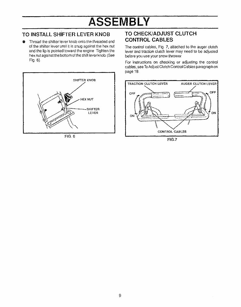
...............ASSEMBLY ...............TO INSTALL SHIFTER LEVER KNOB
• Thread the shifter lever knob onto the threaded endol the shilter lever until it is snug against the hex nutand the lip is pointed toward the engine Tighten thehex nut against the botlom o! the shift lever knob (SeeFig 6)
TO CHECKJADJUST CLUTCH
CONTROL CABLES
The control cables, Fig. 7, attached to the auger clutchlever and traction clutch lever may need to be adjustedbelore you use your snow thrower
For instructions on checking or adjusting the controlcables, see ToAdjust Clutch Control Cables paragraph onpage 18
SHIFTER KNOB
""_"_'\ __H EX N UT
HEX
_._. LEVER
F,GI'6"'
TRACTION CLUTCH LEVER AUGER CLUTCH LEVER
OFF __ FF
I I,ft- _ ]] ]
, .......... ON
CONTROL CABLES
FIG.7

.................. r , HHH'""t' ''"""1' __" ..... ' '"""L.......... -
OPERATIONKNOW YOUR SNOW THROWERREAD THIS OWNER'S MANUAL AND SAFETY RULES BEFORE OPERATING YOUR SNOWTHROWER. Compare the illustrations with your snow thrower to tamiliarize yourself with the location of variouscontrols and adjustments Save this manual for luture reference
AUGER -TRACTION DRIVELEVER LEVER
SPEED SHIFTERLEVER
CHUTE DEFLECTOR
_CRANKASSEMBLY
_BUTTON
CHUTE
SCRAPER BAR
FIG. 8n l m,un,,, ,nil,,, ,U,,,H , nH ,,H,',,,',' , ,.,P..
SEARS SNOW THROWERS conform to the safety standards of the American National Standards Institute
AUGER DRIVE LEVER- Starts and stops the auger andimpeller (snow gathering and throwing)TRACTION DRIVE LEVER - Propels the snow throwerforward and in reverse,
SPEED SHIFTER LEVER - Selects the speed of thesnow thrower (6 speeds forward and 2 speeds reverse)CRANK ASSEMBLY - Changes the direction of snowthrowing through the discharge chuteCHUTE DEFLECTOR- Changes the distance the snowis thrown
DISCHARGE CHUTE. Changes the direction the snowis thrown
HEIGHT ADJUST SKIDS- Adjusts the ground clearanceof the auger housingIGN1TION KEY - Must be inserted to start the engineRECOIL STARTER HANDLE - Starts the engine manu-
--. alI_CHOKE CONTROL - Used to start a cold enginePRIMER BUTTON- Injects luel directly into the carbure-tor manilotd for last slarts in cold weather
THROTTLE CONTROL - Controls the engine speed
10
OPERATIONu J,,J i
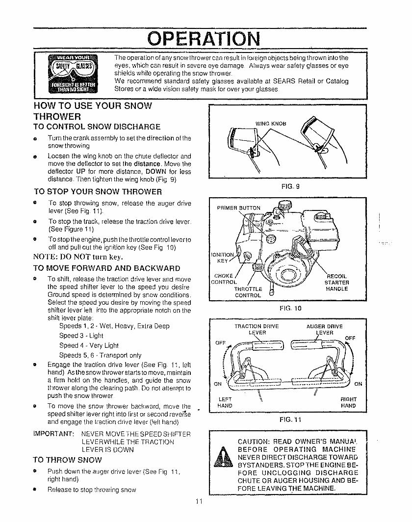
The operation ot any snow thrower can result in foreign objects being thrown into theeyes, which can result in severe eye damage Always wear safety glasses or eyeshields while operating the snow throwerWe recommend standard safety glasses available at SEARS Retail or CatalogStores or a wide vision safety mask !or over your glasses
iii i i, ,1,,1, ,,,,,i , t
HOW TO USE YOUR SNOW
THROWERTO CONTROL SNOW DISCHARGE
® Turn the crank assemMy to set the direction ol thesnow throwing
® Loosen the wing knob on the chute deflector andmove the deflector to set the distance. Move thedeflector UP for more distance, DOWN for lessdistance. Then tighten the wing knob (Fig 9)
TO STOP YOUR SNOW THROWER
WING KNOB
FIG_ 9
• To stop throwing snow, release the auger drivelever (See Fig. 11)
o To stop the track, release the traction drive Iever.(See Figure 11).
• To stop the engine, push the throttle control lever tooff and pull out the ignition key (See Fig 10)
NOTE: DO NOT turn key.
TO MOVE FORWARD AND BACKWARD
o To shift, release the traction drive lever and movethe speed shifter lever to the speed you desireGround speed is determined by snow conditionsSelect the speed you desire by moving the speedshifter lever left into the appropriate nolch on theshift lever plate:
Speeds 1,2 - Wet, Heavy, Extra Deep
Speed 3 - Light
Speed 4 - Very Light
Speeds 5, 6- Transport only
• Engage the traction drive lever (See Fig I1, leltha nd) As the snow thrower starts to move, maintaina firm hold on the handles, and guide the snowthrower along the clearing path Do not attempt topush the snow thrower
e To move the snow thrower backward, move the-,d
speed shifter lever right into first or second reverseand engage the traction drive lever (left hand)
IMPORTANT: NEVER MOVETHESPEEDSHfFTERLEVERWHILE THE TRACTIONLEVER IS DOWN
TO THROW SNOW
• Push down the auger drive lever (See Fig 1I,right hand)
• Release to stop throwing snow
FIG, 10
TRACTION DRIVELEVER
,,,q,,, 1,1,, ,
AUGER DRIVE
_EVEROFF
ON
LEFT RIGHTHAND HAND
FIG. 11
CAUTION: READ OWNER'S MANIJA'.
BEFORE OPERATING MACHINENEVER DIRECT DISCHARGE TOWARDBYSTANDERS. STOP THE ENGINE BE-FORE UNCLOGGING DISCHARGECHUTE OR AUGER HOUSING AND BE-FORE LEAVING THE MACHINE°
- ,m ,,,, , , ,, i , ,, i I,H,,H, I I I
1I

OPERATIONii ....,i i i,,,,.11 Wl...,, i. ,iJ
O USE WHEEL LOCKOUT PIN .................
The lett hand wheel is secured to the axle with aklick pin (See Fig 12A) This unit was shipped withthis klick pin in the locked (through wheel hole)position
For ease of maneuverability in light snow condi-lions, disconnect the klick pin from the wheel lockedposition and push into the single wheel drive (un-locked axle hole only) position (See Fig 12B)
, Make sure that the klick pin is in the single wheeldrive position ol the axle only and not through thelocked position
3EFORE STARTING THE ENGINE
D If the snow thrower must be moved without the aid
of the engine, it is easier to pultthe snow thrower bythe handles rather than pushing
a, Before you service or start the engine, familiarizeyourself with the snow thrower Be sure you un-derstand the function and location of all controls
NOTE: Check tension ot clutch cables before._tarting theengine (See To Adjust The Control Cables paragraphon page 18)
.o Be sure that all lasteners are tight
,o Make sure the height adjust skids are properlyadjusted (See To Adjust Skid Height paragraph onpage 17)
e Check tire pressure (I4 to t7 pounds) See side oftire for maximum inflation Do not exceed maximum
pressure
;FILL OIL:
This snow thrower was shipped without oil in the engine!5W30 oil is included with this unit and must be added to!the engine before operaling Remove the oil fill cap/_dipstick and lill the crank case to FULL line on dipsticki(21 ounces) (See Fig 14) Do not over-fill Tightenthefill capldipstick securely each _ime you check Ihe oi!level
NOTE: Oil must be changed after the lirs_ 2 hours o{operation to extend engine life
For extre me cold operating condilions of 0: F and below.use a partial synthetic 0W30 or 5W30 motor oil for easierstartingFILL GAS:
Fill the fuel tank with clean, fresh, unleaded gradeautomotive gasoline Be sure lhat the conlainer you pourthe gasoline from is clean and free from rust or olherforeign particles Never use gasoline thai may be stalefrom long periods of storage in the confainer
WARNING: Experience indicates tl_a_alcohol blendedfuels (called gasoholor those using elhanol or methanol)
KUCK PIN
. ill, i
12
LOCKEDPOSITION
2-WHEEL DRIVEi
FIG. t2A
KLtCK PIN
UNLOCKEDPOSITION
SINGLE WHEEL DRIVEINH I I.I I I.I Jl'
FIG. 12Bi,, iiJJ. ,i,l,, ii . i,.i,ii
OIL FiLL CAPfDIPSTiCK
NOTE: OIL LEVEL MUSTBE BETWEEN FULL
AND ADD MARK
i JJ,,,i
FiGoi3
can attract moisturewhich leads to separation and forma-tion of acids during storage the fuel system of an enginew_hilei,nstorage Acidic gas can damage the luet systemol an engine while in storage.
To avoid engine problems, the fuel system should beemptied before storage for 30 days or longer Start theengine and let it run until the fuel lines and carburetor areempty Use the carburetor bowl drain to empty residualgasoline kom the float chamber (Fig 37, page 24) Useflesh luel next season (See Storage instructions onpage 24 for additional information )
Never use engine or carburetor cleaner products in thetuel tank or permanent damage may occur

,, ,,,,,,,,,,,,, , ,,,,, ,,,,,, ......................................................
OPERATIONTO STOP ENGINE
o To stop engine, move the throttle control lever toSTOP position and remove key. Keep the key in asafe place. The engine will not start without the key
CARBURETORThe factory settings for the carburetor are for mostconditions_ If the engine is operated underthe foltowingconditions, you can adjust carburetor mixture. See"How To Adjust The Carburetor"(See Service and Ad-justments, page 22).
• The engine has a loss of power or does not runsmooth..
• The engine's operated above 4,000 feet.
TO START ENGINEBe sure that the engine has sufficient oil. Before startingthe engine, be certain that you have read the followinginformation:
COLD START (See Fig. 14)
• Be sure the auger drive and the traction drivelevers are in the disengaged RELEASED positionL
® Move the throttle control to RUN position
® Push the key into the ignition slot Be sure it snapsinto place. Do not turn key. Remove the plasticbag and store extra key in a safe place
• Rotate choke control to FULL choke position _
® Press the primer button in cold weather. Presstwo or three times, while keeping your finger overthe vent hole on the primer button Release fingerbetween primes Additional priming may be neces-sary for the first start if the temperature is below 15"F_ Do not prime if temperature is above 50° F.
• Pull the starter handle rapidly. Do not allow thehandle to snap back, but allow it to rewind slowlywhile keeping a firm hold on the starter handle.
• As the engine warms up and begins to operateevenly, rotate the choke knob slowly to OFFposition. Ifthe engine falters, return to FULL choke,then slowly move to OFF choke position
NOTE: Allow the engine to warm up for a few minutesbecause the engine will not develop full power until itreaches operating temperature
• Run the engine at or near the top speed whenthrowing snow
WARM START
If restarting a warm engine after a short shutdown,rotate choke to OFF instead of FULL and do not push theprimer button.
FROZEN STARTER
If the starter is frozen and will not turn engine:
• Pul! as much rope out of the starter as possible
CHOKE
CON_OL
PRIMER
13
IGNITION RECOILKEY STARTER
THROTTLE CONTROL;i H = =H= i i = H H,H,I=== = HI
FIG°14i i iii i H,H,=,HH,,, i i ill iiliilil l i
_ CAUTION: GASOLINE IS FLAMMABLEAND CAUTION MUST BE USED WHENHANDLING OR STORING IT.
DO NOT FILL FUEL TANK WHILE SNOWTHROWER IS RUNNING,WHEN IT tS HOT, ORWHEN SNOW THROWER IS IN AN ENCLOSEDAREA.
KEEP AWAY FROM OPEN FLAME OR AN ELEC-TRICAL SPARK AND DO NOT SMOKE WHILEFILLING THE FUEL TANK.
NEVER FILL THE TANK COMPLETELY. FILLTHE TANK TO WITHIN1/4"- I/2" FROMTHETOPTO PROVIDE SPACE FOR EXPANSION OF FUEL.
ALWAYS FILL FUEL TANK OUTDOORS ANDUSE A FUNNEL OR SPOUT TO PREVENT SPILL-ING.
MAKE SURE TO WIPE UP ANY SPILLED FUELBEFORE STARTING THE ENGINE.
STORE GASOLINE IN A CLEAN, APPROVEDCONTAINER AND KEEP THE CAP IN PLACE ON
.....THE CONTAINER. ,,,
• Release the starter handle and let it snap backagainst the starter
If the engine still fails to start, push the primer button twoor three times again and repeat the two previous stepsuntil the engine starts. Then continue with the directionsfor cold start.
To help prevent possible freeze-up of recoil starter andengine controls, proceed as follows after each snowremoval job.e Withtheenginerunning, pullthestarterropehard
with a continuous full arm stroke three or fourtit,: _,
Pulling of starter rope will produce a loud clatte_ '_sound. This is not harmful to the engine or starter
o With the engine not running, wipe all snow andmoisture from the carburetor cover in area of controllevers Also move throltle control, choke control,and starter handle several times.
OPE ATION,ll i llllll i,,i lU ill
,LD
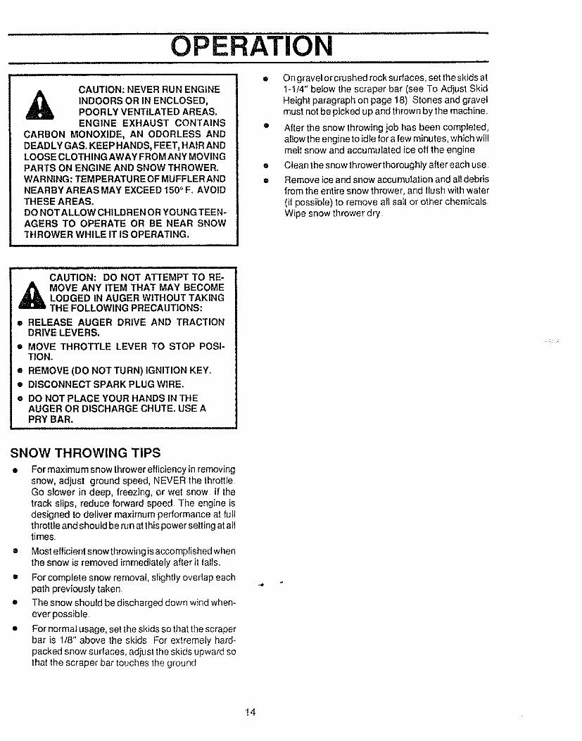
CAUTION: NEVER RUN ENGINE
INDOORS OR IN ENCLOSED,POORLY VENTILATED AREAS.ENGINE EXHAUST CONTAINS
CARBON MONOXIDE, AN ODORLESS ANDDEADLY GAS. KEEP HANDS, FEET, HAIR ANDLOOSE CLOTHING AWAY FROM ANY MOVINGPARTS ON ENGINE AND SNOW THROWER.WARNING: TEMPERATURE OF MUFFLER ANDNEARBY AREAS MAY EXCEED 150 ° Fo AVOIDTHESE AREAS.DO NOT ALLOW CHILDREN OR YOUNG TEEN-AGERS TO OPERATE OR BE NEAR SNOWTHROWER WHILE IT IS OPERATING.
i i i u i i iii i iiiiiiiiiiiiiiiiiiiiiiiiiiii
O ngravel or crushed rock surfaces, set the skids atI-1/4" below the scraper bar (see To Adjust SkidHeight paragraph on page 18)_Stones and gravelmust not be picked up and thrown by the machine..
• After the snow throwing job has been completed,allow the engine to idle for a few minutes, which willmelt snow and accumulated ice off the engine
• Clean the snow thrower thoroughly after each use.
• Remove ice and snow accumulation and all debrisfrom the entire snow thrower, and flush with water(if possibte) to remove all sait or other chemicalsWipe snow thrower dry
CAUTION: DO NOT ATTEMPT TO RE-
,_ MOVE ANY ITEM THAT MAY BECOMELODGED IN AUGER WITHOUT TAKINGTHE FOLLOWING PRECAUTIONS:
• RELEASE AUGER DRIVE AND TRACTIONDRIVE LEVERS.
• MOVE THROTTLE LEVER TO STOP POSI-TION,
® REMOVE (DO NOTTURN) IGNITION KEY.• DISCONNECT SPARK PLUG WIRE.
e DO NOT PLACE YOUR HANDS IN THEAUGER OR DISCHARGE CHUTE. USE APRY BAR.
SNOW THROWING TIPSIt For maximum snow thrower efiiciency in removing
snow, adjust ground speed, NEVER the throttleGo slower in deep, freezing, or wet snow If thetrack slips, reduce forward speed The engine isdesigned to deliver maximum performance at fullthrottle and should be run at this power setting at alltimes_.
® Most efficient snowthrowing is accomplished whenthe snow is removed immediately after it falls.
• For complete snow removal, slightly overlap eachpath previously taken.
o The snow should be discharged down wind when-ever possible.
• For normal usage, set the skids so that the scraperbar is 1/8" above the skids For extremely hard-packed snow surfaces, adjust the skids upward sothat the scraper bar touches the ground
14

......................................... , i, i, i iiii1,,,, i,, i iii 1,1, LI,
CUSTOMER RESPONSIBILITIEH,,,,,,, , =,,, ,,, =H.,,. ,, , =,,,,,, =H,,, ,,,=.,,,,,,, =====,==,1,=,,, H, m,,,
GENERAL RECOMMENDATIONS .............................................
The warranty on this snow thrower does not cover itemsthat have been subjected to operator abuse or negli-gence To receive full value from the warranty, operatormust maintain snow thrower as instructed in this manual.
Some adjustments will need to be made periodically toproperly maintain your snow thrower
All adjustments in the Service and Adjust ments section ofthis manual should be checked at least once eachseason
AFTER FIRST USE
" Check for any loose or damaged parts
• Tighten any loose fasteners
• Check and maintain the auger
• After each use, remove all snow and slush off thesnow thrower to prevent freezing of auger or con-trois
o Check controls to make sure they are functioningproperly
o If any parts are worn or damaged, replace imme-diately
SNOW THROWER
LUBRICATION - EVERY FIVE HOURS
• Lubricate the flange on the discharge chute everyfive (5) hours during use and before storage (SeeFig 17)
® See Lubricalion Chart diagram on page 25 for lu-brication points and type of lubricant
LUBRICATION - EVERY TEN HOURS
* Auger Shaft- For storage, lubricate auger shaft (SeeFig 16) with aclinging type grease such as LubriplaieWhen replacing shear bolts, remove shear botts andlubricate auger shaft (see To Replace Shear Boltparagraph on page 22)
* The chute control rod, used to change the directionof the snow discharge, needs to be lubricated fre-quently and before storage (See Fig 17)
o See Lubrication Chart diagram on page 25 for lu-brication points and type of lubricant "'
FIG. 15,,,,,,, , ,,,,,,, i
LUBRICATE AUGER SHAFTi i ii1,1,1,,, i i1,.
FIG. 16
:_HUTE
DISCHARGE _l_ \_ • _IL//_ _CONTROLCHUTE _ tt _ \,_','_1" t/Y/_ '''" ROD
FLAN__
FIG. 17
damage will result Fill zerk only until grease becomesvisible below bearing assembly located under greasezerk. See Lubrication Chart on page 25
LUBRICATION - EVERY 25 HOURS
Disc Drive Plate- Using a hand grease gun, lubricatewith a Hi Temp EP Moly grease, zerk located be-neath the disc drive plate (See Fig 18 inset) every 25hours and at the end of the season and/or beforestorage To grease zerk, turn disc drive plate clock-wise by hand until zerk is clearly visible at lrontcenter DQ NOT overtilt or allow grease 1ocome incontact with the disc drive plate or friction wheel or
LUBRICATION - BEFORE STORAGE
• Remove both wheels, grease (any automotive typegrease) both axles (See Fig 15) and reptacewheelsDo this al least once a year and/or prior to storage
t5

i =ll,, i i i,i , i= ,lll,l,,i, =IHI=I = ,= H,H= -
CUSTOMER RESPONSIBILITIESN,i ii,i, ............................t=
LUBRICATION HEX SHAFT AND GEARS
• Hex Shaft and Gears - Hex shaft and gears requireno lubrication All bearings and bushings are lifetimelubricated and require no maintenance (See Fig 18)
NOTE: Any greasing or oiling of the above componentscan cause contamination of the friction wheel it the discdrive plate or friction wheel come in contact with greaseor oil, damage to the friction wheel will result
Should grease or oil come in contact with the disc driveplate or friclion wheel, be sure to clean the plate andwheel thoroughly
NOTE: For storage, the hex shall and gears should bewiped with 5W-30 motor oil to prevent rusting (See Fig18)
e Auger Gear Box - The auger gear box has beenfactory lubricated for life If for some reason lubricantshould leak out, have auger gear case checked by acompetent repairman
ENGINE
LUB RiCATION
Check the crankcase oil level (See Fig 19) beforestarting the engine and after each five (5) hours otcontinuous use Add S A E 5W-30 motoroil as needed
Tighten fill cap/dipstick securely each time you check theoil level S AE 5W-30 motor oil may be used to makestarting easier in areas where the temperature is 20" F orlower
OIL RECOMMENDATION
Only use high quality detergent oil rated with API serviceclassitication SG Select the oil's viscosity grade accord-ing to your expected operating temperature:
RECOMMENDED VISCOSITY GRADES
|coLDER<_ _>WARMER
5W30 SAE30
NOTE: Although multi-viscosity oils improve starting incold weather, these multi-viscosity oils will result in in-creased oil consumption when used above 32:F Checkyour engine oil level more frequently to avoid possibleengine damage from running low on oil
Change the oil after first lwo hours ol operation and every25 hours thereafter or at least once a year if tl_e snowthrower is nol used for 25 hours (See Fig 20)
• Position snow thrower so that the oil drain plug islowest point on the engine Remove of! drain plugand oil lill cap/dipstick Drain oil into a suitablecontainer Oil wilt drain more freely when warm
WHEEL
(Require NoLu brication)
/
/
DRIVE•, PLATE
ZERK
OIL FiLL CAP_DIPSTICK
_OIL DRAIN PLUG
FIG. 20
• Replace oil drain plug and tighten securely Refillcrankcase with SAE 5W30 motor oil
SPARK PLUG
=, Make sure that the spark plug is tightened securelyinto the engine and the spark plug wire is attached1othe spark plug
• If a torque wrench is available, torque plug to 18 to
23 foot pounds
• Clean the area around the spark plug base beforeremoval lo prevenl dirt from entering the engine
Clean the spark plug and reset the gap periodicallyat 030 inch

Thissnowthroweris equippedwithtwoheightadjust-meritskids,locatedonthe outside of the auger housing(See Fig 21) These skids elevate the front of the snowthrower
For normal hard surfaces, such as a paved driveway orwalk, adjust the skids as follows:
• Check tire pressure (14 to 17 pounds)
• Place the extra shear bolts supplied (found in partsbag) under each end of the scraper bar near but notunder the skid
• Loosen the skid mounting nuts (See Fig 21), andadjust the skids to allow the front of the snowthrower to rest on the shear bolts Retighten themounting nuts,
• Set the skid on the other side at the same height
NOTE: For graveled or uneven surfaces, raise the frontof the snow thrower by moving the skids down This wilthelp prevent rocks and other debris from being picked upand thrown by the auger
TO ADJUST SCRAPER BAR
After considerable use, the metal scraper bar wilt have adefinitewearpattern The scraperbarinconjuncfionwiththe skids should be adjusted to allow tt8" between thescraper bar and the sidewalk or area to be cleaned Thescraper bar may have to be returned to its original lowersetting to maintain the original pertormance level Toadjust:
• Position the snow thrower on a level surface
• Make sure both tires are equally inflated Propertirepressure is 14 to 17 PSI See side of tire {ormaximum inflation Do not exceed sidewall maxi-mum pressure on tire
• Loosen the carriage bolts and nuts securing lhescraper bar to the auger housing -"
o Adjust the scraper bar to the proper position
• Tighten the carriage bolts and nuts, making surethat the scraper bar is parallel with the workingsurface
SKID MOUNTING NUTS
For extended operation, the scraper bar may bereversed lflhe scraper bar must be replaced due towear, remove the carriage bolts and nuls and installa new scraper bar
AUGER HOUSING HEIGHT ADJUST SKID
FIG. 2t
........................... _ i i i i innllU
CAUTION: BE CERTAIN TO MAINTAINPROPER GROUND CLEARANCE FORYOUR PARTICULAR AREA TO BECLEARED, OBJECTS SUCH AS GRAVEL,
STONES OR OTHER DEBRIS, IF STRUCKBY THE IMPELLER, MAY BE THROWNWITH SUFFICIENT FORCE TO CAUSEPERSONAL INJURY, PROPERTY DAM-AGE OR DAMAGE TO THE SNOWTHROWER..
i , ,i ,,, i i
TO ADJUST CHUTE
CRANK ASSEMBLY
If you cannot rotate the chute crank fully to the left and tothe right, you need to adjust the chute crank (See Fig22)
o Loosen both t/2" nuts on the crank adjusting rod(using 3/4" wrenches)
• Rotate the adjusting rod in or out to allow aboutt/8" clearance between the notch in the flange andthe outer diameter o! the worm
e Once this clearance is set, tighten the nuts
NOTE: Be sure the crank does not touch the side of theengine or the cover will be scratched
PLASTIC\. NOTC.EO.SECT ONCAP COTTER _ "_,_._
_. PiN /h/8 INCH CLEARANCE] .__,..-..-..
FL
_ '-.,.-tz \ \ /z Z"_ 112 iNCH
C.AN ,,O.',ST,NORO0" WORM
FIG,, 22
17

3 ADJUST THE CLUTCH CONTROL
ABLES_riodic adjustment of the cables may be required due tormat stretch and wear on the bells Tocheck lor correctjustment, the control lever must be in the full forwardsition, restingontheptasticbumper Thecontrolcablese correctly adiusted when the center of the 'Z' tilting is_tween the center and top of Ihe hole in the clutch lever_dthere is no droop in the cable (See Fig 23)
adjustmenl is necessary:
Disconnect "Z' Fitting lrom drive lever
Push the cable through the spring (See Fig 24) toexpose the threaded portion of the cable
Hold the square end of the threaded portion withpliers and adjust the tocknut in or out until the excessslack is removed (See Fig 24)
Pull the cable back through the spring and connectthe cable
Do the same for the other lever cable
OTE: Whenever the traction drive or auger belts areJiusted or replaced, the cables w{IIneed to be adjusted
"O ADJUST BELTS
AUGERLEVER
CONTROL LEVERMUST BE IN FULL
I ORWARD PQsrrloN(Just cortt actingPlastic Bumper} WHENCHECKING
,PLASTIC BUMPER
FIG, 23inlH,, i, lU ,H,ll u,,p , .................. ,tllll
END
LOCKNUT
FIG. 24
efts stretch during normal use If you need to adjust_e belts due to wear or stretch, proceed as follows:
,_UGER DRIVE BELT (See Fig_ 26)
your snow thrower will not discharge snow, check the:ontrol cable adjustment If it is correct, then check theondition of the auger drive belt It may be loose or_amaged If it is damaged, replace it See To Replace:,ells paragraph on page 19 If the auger drive belt isrose, adjust as follows:
Disconnect the spark plug wire
Remove the belt cover (See Fig 27, page 19)
Loosen the nut on the auger idler pulley (See Fig 26)and move the pulley toward the belt about 1/8"
Tighten the nut
Press the auger drive lever Check the tension on thebelt (opposite auger idler pulley) The belt shoulddeflect about 112'"with moderate pressure (See Fig25)
IOTE: You may have to move the auger idler pulley_ore than once to obtain the correct tension
Replace the be!t cover
Check the clutch control cable adjuslment
Reconnecf the spark plug wire
°RACTION DRIVE BELT
__ DRIVE
POLLE,,AUGERlULER----%) _.jF.---It2INCH
\ ' ,/"_'_ IMPELLER
PULLEY
ii i1[ iiiiiiii i I I iiiiiiiiii ii iii iiill I I
FIG_ 25
(Right
;ACTION DRIVEIDLER PULLEY
AUGER IDLER
PULLEY
FIG, 26
he traction drive bell has constanl spring pressure andDes not require adjustment
• Replace the traction drive belt it it is slipping (see ToReplace Belts paragraph on page !9)
!8

SE, ............................................ i, H,Jl
TO REPLACE BELTS
The drive belts on this snow lhrower are ol specialconstruction and should be replaced with originalequipment belts available from your nearest Sears Storeor Service Center
You will need lhe assistance of a second person whilereplacing the belts
Drain the gasoline from the fuel tank by removing the tueiline Drain the gas and reinstall the fuel line
OT,O. iDOORS, AWAY FROM FfRE OR FLAME_ I
AUGER DRIVE BELT
If your snow thrower will not discharge snow, and theauger drive belt is damaged, replace it as follows:
e Disconnect the spark plug wire
® Remove the belt cover (See Fig 27)
• Loosen the belt guides (See Fig 28) and pulf awayfrom the engine drive pulley
e Loosen the nut on the auger idler pulley (See Fig28) and pull idler pulley away from the belt
• Remove belt from engine drive pulley
o Remove top two bolts securing auger housing tomotor mount frame Loosen bottom two bolts (SeeFig 30, page 20)
o Auger housing and motor mount frame wilt sepa-rate, hinged by bottom two bolts
® Remove brake arm from housing Do not removespring
o Remove old belt from the auger drive pulley
o Install new replacement belt of the same type ontothe auger pulley
• Reinstall brake arm into housing Ensurebrake armis lully inserted into housing and brake pad is ridingin pulley groove
g Position belt onto engine drive pulley
• Adjust the auger drive belt (see To Adjust AugerDrive Belt paragraph on page t8)
• Adjust the belt guides (see To Adjust The Belt
Guides paragraph on page 20) _,o Replace top two bolts Re-tighten bottom two boltso Reinstall the belt cover
• Check the clulch control cable adjustment (seepage I8)
Reconnect the spark plug wireO
TRACTION DRIVE BELT (See Fig. 28)
If your snow thrower will not move forward, check thetraction drive belt for wear (Check other causes afso inthe Trouble Shooling Points section ) If the _raction drive
VICE AND ADJUSTMENTS
BELT COVER /
FIG. 27.................................. iiii i
TRACTION DRIVE TRACTION DRIVE BELT
DRIVEBELT
BELT
(RighL Hand)
TRACTION DRIVEIDLER PULLEY
BELT GUIDE
DRIVEPULLEY
IDLERPULLEY
........................................ .i
FIG. 28
belt needs to be replaced, proceed as Iotlows:
e Disconnect the spark plug wire
• Remove the bell cover
Loosen belt guides and pull guides away from theengine drive pulley
• Loosen nut on auger idler and pull auger idler pulleyaway from betl
• Remove auger drive belt from engine pulley
• Pull the traction drive belt idler pulley away from thedrive belt
Remove drive belt
• Position new replacement belt of the same typeonto traclion pulley
o Pull idler pulley away from belt, aTIowing belt to bepositioned onto engine pulley
Release idler pulley Ensure idler pulley is properlyengaged with belt
• Reinstall auger drive belt on engine
• Adiust belt guides and tighten the mounting so: : ,;Js(see To Adjust The Belt Gu ides paragraph on _.-'._ge2O)
Readjust auger idler to adjust bell See page t8
Reinstall lhe belt cover
o
O
e Reconnect the spark plug wire
19

................ ii i i
SERVICE ANi1, i,,, , ii m,,,,,,,,,,H ii ,,,,,n
rO ADJUST THE BELT GUIDES
here are two belt guides on your snow thrower, a left andight After you replace the traction drive belt, you need to_djust one or both of the belt guides Proceed as followsor each belt:
Disconnect the spark plug wire
D Remove the belt cover by removing the screw andflatwasher on the left and right hand sides See Fig27 page 19.
D Engage the auger drive clutch lever
Measure the distance between the belt guides andthe belt (See Fig 29) The distance should be 3/32"for each guide.
IH H, r I, IHHI I, I I I1,,,1,1
ADJUSTIVIE TSMOTOR MOUNT FRAME
\\ _._ BOTTOM
SIDE) I
LOOSEN BOTTOM BOLTS
IEAC.S,DEI................ cao.t.lo,.Vi.ewl
D If adjustment is necessary, loosen the belt guidemounting bolts. Move the belt guides to the co_'rectposition. Tighten the mounting bolts
D Reinstall the belt cover.
Reconnect the spark plug wire
......................, ._..-_ _ ._'UGER DRIVE PULLEY
3132 INCH"__ BELT GUIDE
BELT GUIDF_" "_._ _,.(Le|l Hand)
(Right Hand)A-- _\_"3132 INCH
_IMPELLER
FIG, 29
TO ADJUST THE FRICTION WHEEL
If the snow thrower will not move forward, you need tocheck the traction drive bell, the traction drive cable or theMction wheel If the frictionwheel is damaged, itwilt needto be repiaced. See To Replace Friction Wheel parag raphon page 21 If the friction wheel is not worn, check theadjustment, as follows:
• Disconnect the spark plug wire
o Drain the gasoline from the gas tank
g Stand snow thrower on the auger housing end
® Remove the bottom panel (See Fig 30)
® Position the shifter lever in first (1) gear
o Note the position of the friction wheel on the discdrive plate. The right outer side of the disc drive plateshould be 3" from the center of the friction wheel
(See Fig 3tA)
If adjustment is necessary:
FIG. 30
• Move frictionwheel to proper position as indicatedin previous step (Fig 31A).
• Re-tighten bolts in speed selector Iever
® Reinstall the boitom panel.IIH H IHI H,H ,i HH,,
_____DIscDR=VE
__ _ PLATE
3"1<
i,i ii
FIGo31A
SPEED SELECTOR LEVER
(Rear View)
FIG. 31B
= Loosen bolts in speed selector lever (See Fig 31B)
2O

................ ,,,,,,u . iii ii i iiii ii iiiiiii iiii L/ iiil/ LI ii iiiiiiiiiiiii I I I I iiiiiiiii I
SERVICE AND ADJUSTMENTSH.L =,,,, H,H,,,= H= =,,H,, ,.,H = HH,N. =,
,,,N =, , .,, , . =1 '" ", ' "" I L
TO REPLACE FRICTION WHEELIf the snow thrower will not move forward, and the frictionwheel is worn or damaged, you need to replace it asfollows: (First allow the engine to cool.)
IA ICAUTION: DRAIN GASOLINE OUTDOORSAWAY FROM FIRE OR FLAME.
• Drain the gasoline from the fuel tank by removingthe fuel line Drain the fuel and reinsta!Ithe fuel {ine
• Disconnect the spark plug wire
• Stand the snow thrower up on the auger housingend (See Fig 33)_
e Remove the botlom panet (See Fig 30, page 20)
e Remove the three (3) fasteners securing the frictionwheel to hub (See Fig 32) and set fasteners aside
e Remove the four bolts securing the bearing plates(both sides)
• Remove right side bearing plate. Leave Hex shaft inoriginal position (See Fig 33).
e Remove friction wheel from hub Slip friction wheetoff hex shaft towards right side (See Fig 33)
o Position new friction wheel onto hub
e Install bearing plates to original position Ensurehex shaft is engaged with both bearing plates
• Secure beating plates using bofts removed earlier
® Secure Ifiction wheel to hub using fasteners re-moved eartier Ensure hex shalt turns freely
NOTE: Ensure friction wheel and friction disc are free
from grease or oil
• Replace bottom panel
• Lower the snow thrower onto the tires
HUB
HEX SHAFT
FASTENERS
(screws,Iockwashers, 'BEARING
and nuts) PLATES
/ \/ \
i .... ousmNG
(UNIT STANDING ONAUGER HOUSING END)
I,,N i ii i.. ,i, L N, I
FIG. 33
21

i i ,i i inll i1 ii i lU,,,llll nnl i,nlll nil IlUl,,,i Inl, I I .... ,i Ii Ill
SERVICE A DADJUST TSTO REPLACE AUGER SHEAR BOLT ................................
The augers are secured lo the auger shaft with specialbolls (See Fig 34) that are designed to break (to protectthe r0achine) if an object becomes lodged in the augerhousing Use of a harder bolt will destroy the protectionprovided by the shear bolt
IMPORTANT: TO iNSURE SAFETY ANDPERFORMANCE LEVELS, ONLYORIGINAL EQUIPMENT SHEARBOLTS SHOULD BE USED WHENREPLACING SHEAR BOLTS, BE SURETO REPLACE SHEAR BOLTSPACERS
To replace a broken shear boll, proceed as follows:
• Move the throttle to STOP and turn off al_controls
• Disconnect the spark plug wire Be sure all movingparts have stopped
e Remove the broken shear bot{
= Lubricate the auger shaft by squirting oil into theshear bolt hote in the auger shaft. Then rotate theauger to distribute the oil on the shaft.
• A{ign the hole in the auger with the hole in the augershaft Install the new shear bolt, shear bo!l spacer,and iocknut provided in parts bag
e Reconnect the spark plug wire
TO ADJUST CARBURETOR
The carburelor (See Fig 35 and Fig 37(page 24) hasbeen pre-set at the factory and readjustment should notbe necessary However, if the carburetor does need lo beadjusted, proceed as follows:
• Close the high speed adjusting screw by hand
• Do not over4ighten
• Then open it 1-1/4 to 1-t/2 turns
• Close the idle adjusting screw by har_d Do not over-tighten
• Then open it 1-1/4 to 1-1/2 turns
• Start the engine and let it warm up
• Set the throttle control to RUN Adjust the highspeed adjusting screw in unti! the engine speed orsound alters Adjust the screw out until the enginespeed sound alters Note the difference betweenthe two limits and set the screw in the middle of lherange
• Let the engine run undisturbed for 30 seconds aftereach setling Io allow lhe engine to reacl to theprevious adjustment
• Set the throttle control to IDLE Adjust the idleadjusting screw in until the engine speed drops,then adjust the screw out until the engine speeddrops Nole the difference between the two limits
SHEAR
LOCK NUT
SHEAR BOLTSPACER
AUGER SHAFT
FIG. 34i i iiiii L iiiu lit ill ii
j CARBURETOR
_ IDLE ADJUSTING SCREW
==_==_) (Close {inger tight only)
/ _t_,--=_.,____..,._ HiGH SPEED ADJUSTING/_ SCREWBOWL DRAIN (Close linger tight only)
I II II I IIIIIj IIU ii iiiii iiiiiiiiiiiii
FIG. 35
and set the screw in the middle of the range
If the engine tends to stall under load or does notaccelerate from tow speed to high speed properly,adjust the high speed screw out in 1/8 turn incre-ments until the problem is resolved. Let the enginerun for 30 seconds between settings
IMPORTANT: NEVER TAMPER WITH THE ENGINEGOVERNOR, WHICH IS FACTORY SETFOR PROPER ENGINE SPEEDOVER-SPEEDING THE ENGINEABOVE THE FACTORY HIGH SPEEDSETTING CAN BE bANGEROUSIF YOU THINK THE ENGINE-GOVERNED HIGH SPEED NEEDSADJUSTING, CONTACT YOURNEAREST SEARS SERVICE CENTER,WHICH HAS THE PROPEREQUIPMENT AND EXPERIENCE TOMAKE ANY NECESSARYADJUSTMENTS
22

TO ADJUST OR REPLACETHE SPARK PLUG
Ifyou have difficulty starting you r snow thrower, you mayneed to adjust or replace the spark plug. Follow theinstructionsbelow,
Replace the spark plug if the electrodes are pitted orburned or if the porcelain is cracked
TO ADJUST:
= Clean the spark plug by carefully scraping theelectrodes (do not sand blast or use a wire brush)
• Be sure the spark plug is clean and free of foreignmaterial. Check the electrodes gap (See Fig 36)with a wire feeler gauge and reset the gap to ,030inch if necessary.
TO REPLACE:
• If you need a new spark plug, use only the properreplacement spark plug (See page 4)
• Set the gap to .030.,
.030 GAP
FIG. 36
• Before installing the spark plug, coat its threadslightly with oil or grease to ensure easy removal,
• Tighten the plug firmly into the engine.
• If a torque wrench is available, torque the ptug to 18to 23 ft - tbs,
23

==q ,L ,,= i =,,,,,,. = , ,=,,H,,, ==,,,,,i, 'ILL
CAUTION: NEVER STORE YOUR SNOWTHROWER INDOORS OR IN AN EN-CLOSED, POORLY VENTILATED AREA
IF GASOLINE REMAINS IN THE TANK. FUMESMAY REACH AN OPEN FLAME, SPARK OR PI-LOT LIGHT FROM AFURNACE, WATER HEATER,CLOTHES DRYER, CIGARETTE, ETC.
To prevent engine damage (if snow thrower is not usedfor more than 30 days) follow the steps below
ENGINE STORAGE
Gasoline must be removed ortreated to prevent gumdeposits from forming in the tank, filter, hose, andcarburetor during storage. Also during storage, al-cohol blended gasoline that uses ethanol or metha-nol (sometimes called gasohol) attracts water. It actson the gasoline to form acids whtch damage theengine.
To remove gasoline, run the engine until the tank isempty and the engine stops Then drain remaininggasoline from carburetor by pressing upward onbowl drain Iocated on the bottom of carburetor (SeeFig. 37)
If you do not want to remove gasoline, a fuelstabilizer (such as Craftsman Fuel Stabifizer No33500) may be added to any gasoline left in the tankto minimize gum deposits and acids If the tank isalmost empty, mix stabilizer with fresh gasoline in aseparate container and add some to the tank.ALWAYS FOLLOW INSTRUCTIONS ON STABI-LIZER CONTAINER, THEN RUN ENGINE ATLEAST 10 MINUTES AFTER STABILIZER ISADDED TO ALLOW MIXTURE TO REACH CAR-BURETOR. STORE SNOWTHROWER 1NA SAFEPLACE. SEE WARNING ABOVE.
You can keep your engine in good operating condi_tion during storage by:
* Changing oil (See page 16)
e Lubricating the piston/cylinder area. This can bedone by first removing the spark plug and squirtinga few drops of clean engine oil into the spark plughole Then cover the spark plug hole with a rag toabsorb oil spray. Next,'rotate the engine by pultingthe starter rope fully out two or three times Finally,reinstall spark plug and attach spark plug wire
,,,,, ,,,,,,,,
FIG, 37
SNOW THROWER STORAGE
* Thoroughly clean the snow thrower.
e Lubricate all lubrication points (see the CustomerResponsibilities section on pages 15-16)
o Be sure that a!l nuts, bolts and screws are securelyfastened. Inspect all visible moving parts for dam-age, breakage and wear Replace it necessary
® Touch up al! rusted or chipped paint surfaces; sandlightly before painting
a Cover the bare metal parts of the blower housingauger and the impeller with rust preventative, suchas a spray lubricant.
NOTE: A yearly checkupor tune-up by a SEARS ServiceCent er is a good way to insu re that you r snow thrower willprovide maximum performance for the next season
LUBRICATION
OTHER
e 1! possible, store your snow thrower indoors withgas removed and cover it to give protection fromdust and dirt
IMPORTANT:
lithe machine must be stored outdoors, block up thesnow thrower to be sure the entire machine is offthe
ground,
Cover the snow thrower with a suitable protectivecover that does not retain moisture. Do not use
plastic or vinyt
NEVER COVER SNOW THROWERWHILE ENGINE AND EXHAUSTAREAS ARE STILL WARM
24

=H=NmIH
RVICE ECOMMENDA ONSm= =m ,====,,,,,=
SERVICE RECORDS
Fill in dates as you completeregular service
SCHEDULE
After Before As Every Every Every Each BeforeFirst2 Each Needed 5 10 25 Season Storagehours Use Hours Hours Hours
SERVICEDATES
Check Engine Oil Level,,,,,,,,i ........
Change Engine Oil
Tighten AII Screws and Nuts
Check Traction Crutch Cable
Adjustment (See Cable Adjuslment)
v" v" v"
Replace Spark Plug
Adjust Drive Belts
v' v"
Lubricate All Pivot Points
Lubricate Auger Shaft (See Shear
Bolt Replacement)
Check Fuel
Drain Fuel
Check Auger Clutch Cable
Adjustment (See Cable Adjustment)
Lubricate Disc Drive Plate Zerk (See
Customer Responsibilities)
v" v"
LUBRICATION CHART
Lubricate auger shaft.Coat with a clin
grease such as Lubriplate orfiber impregnated grease,
Lubricate Disc DrivePlate Zerk with a Hi
Temp EP MolyGrease.
\
25
..... TROUBLE SHOOTING POINTS................................................... i,. ,,.,, HH, ill II,t lU,II,J I UlUI
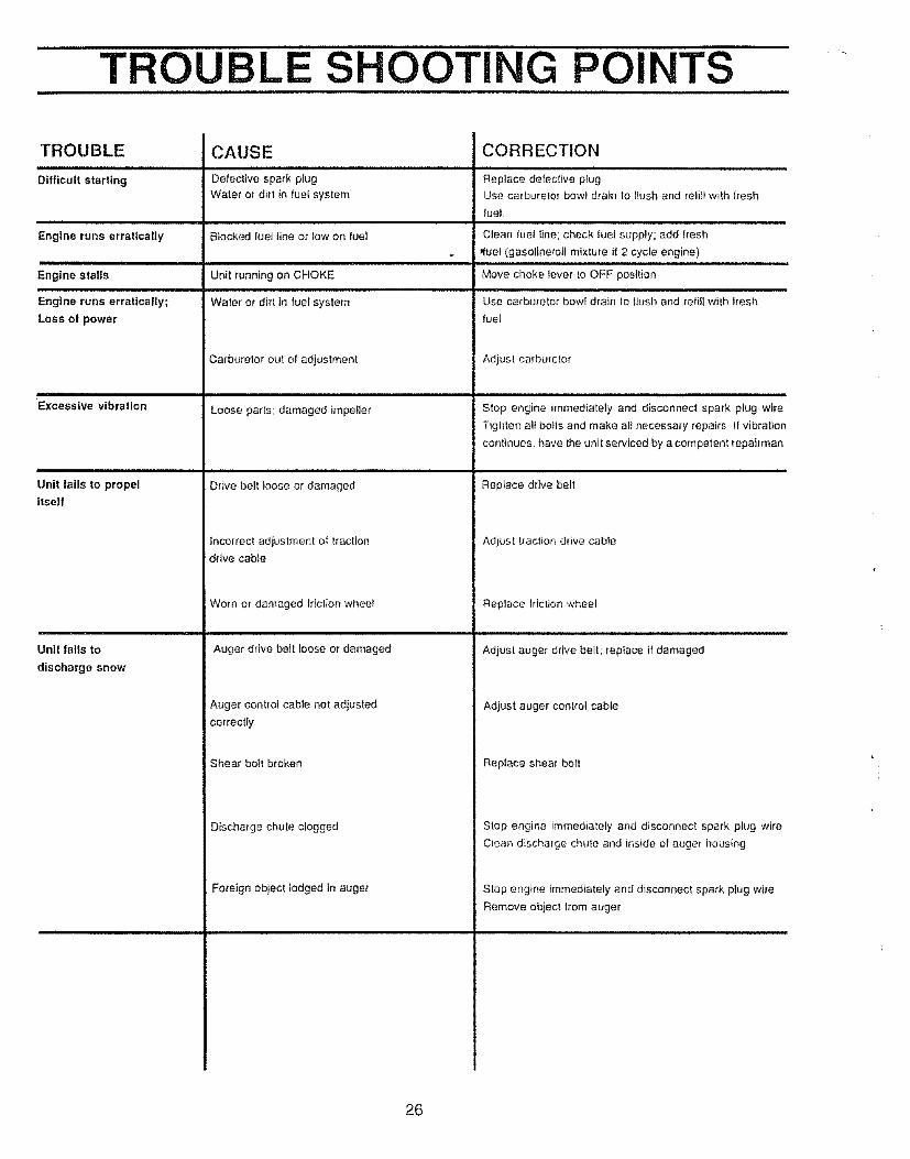
TROUBLE
Difficult starting
Engine runs erratically
Engine stalls
Engine runs erratically;
Loss of power
).n,l,.nr.nnnnln i i ii
Excessive vibration
i
Uni! fails to propel
itself
Unit fails to
discharge snow
CAUSE
Defective spark plug
Water or dirt in tue! system
Blocked fuel line or tow on fuel
Unit running on CHOKE
Water ot dirt in fuel system
Carburetor out of adjustment
Loose parts; damaged impeller
Drive belt loose or damaged
Incorrect adiustment of traction
drive cable
Worn or damaged friction whee!
Auger drive belt loose or damaged
Auger control cable not adjusted
CORRECTION
Replace defec{ive plugUse carburetor bowl drain to flush and reli}lwith lresh
fue!
Clean luet tine; check fuel supply; add fresh
ffuel (gasoline,oil mixture if 2 cycle engine)
Move choke lever to OFF position
Use carburetor bow! drain to llush and refitl w}th fresh
fuel
Adjust carburetor
Stop engine immediately and disconnect spark plug wire
Tighten all boils and make al} necessary repairs If vibration
continues, have the unit serviced by a competent repairman
Replace drive belt
Adjust traction drive cable
Replace Motion wheel
Adjust auger drive belt; replace if damaged
Adjust auger control cable
correctly
Shear bollbroken
Discharge chute clogged
Fo_'eign object lodged in auger
Replace shear bolt
Stop engine immediately and disconnect spark plug wire
Clean discharge chute and inside of auger housing
Stop engine immediately and disconnect spark plug wire
Remove obiec! Irom auger
26

ii
NOTESL J,
27

CRAFTSMAN 22" SNOW THROWER 536.886531
HANDLE ASSEMBLY REPAIR PARTS1",
1t
4
55
2
!9
18
10/
/
5
: 10
21
u
_F.).
23456789
1011
PART NO,
9552-8301123471071710607103711261
307976307978
414035354049
PART NAME
Handle, UpperScrew, Hex, 5/16-18 x 2-3/4 InFlatwasher, 1t/32 InLockwasher, Sptil 5/t6 InNut, Hex, 5/16-t8 ThdSlop, P_asfic, 5/16Traction Drive Lever, LHAuger Drive Lever RHPin, Clulch Handle PivolNut. Push On Cap 5/16 InBumper. Handle
/
REF ]NO. I
12 t13 l14 I15 l
17 I!8 I19 ]20 I
PART NOo PART NAME
1579579869
167371035
308146580667-83070985
580639-83012619
325951
Cable, ClutchSpring, Drive Clutch LHSpring, Auger Clutch RHNut, Hex Nyl, 114_20InBoot, Clutch SpringHandle, LowerScrew, HHC, 5/16-18 x 3/4 InShift Plate BracketScrew, HHC, 5/16-!8 x 2 00 inOwner's Manual
Indicates Slandard Hardware tlems3'_8782,3"_4002 C
28

CRAFTSMAN 22" SNOW THROWER 536.886531
CHUTE CONTROL ROD REPAIRPARTS
1t
1918 \
15
18
2221
RERNO.
123456789
1011
PART NO,
3256087107271082
104307399309312304872
71457148
30814571045
PART NAME
Crank & Worm AssemblyFlatwasher, 406x 8lx 066Pin. CotterCap, PlaslicHandle Grip, Chute Control RodFlatwasher, 39x 70x 05Ring, RetainerBolt, EyeGrommet, Eye BoltBool, Eye Bolt, Chule CrankNut, Hex Jam. 3/8-I6 Thd
REENO.t213t4!5161718!9202122
PART NO.
30934471046
1t627052
309059709937106071037
705570587059
PART NAME
Adapter, Boot to HandleNut, Hex Nyl 3/8-16 ThdBracket, Chute Control R HBracket, Chute Control L HBracket, Chute RotateBolt, Carriage, 5/16-18x314 InLockwasher, Split, 5/16 InNut, Hex, 5/16-18 ThdRod, Chute ControlNut, Hex Jam, 1/2-20 ThdLockwasher, Split, 1/2 In.
::: Indicales Standard Hardware Items
29
319044 -314008D

CRAFTSMAN 22" SNOW THROWER 536.886531
AUGER HOUSING REPAIR PARTS
REENO.
123456789
101t121314
PART NO.
58312457739971371
583219326322
70983710717106071037
583130-854581395-853302623
7106771059
PART NAME
Puiley, Auger DriveScrew, Set, 5/t6-18 x I/2 In
Key, SquareSpacer, SteeveBearing & Retainer AssemblyScrew, HHC 5/16-18 x 5/8 InFlatwasher, 11/32 InLockwasher, Splil, 5/16 inNut, Hex, 1/4-20 ThdHousing, Auger AssemblyBlade, Scraper, 22 InBolt, Carriage, 1/4-20x5/8 InFlatwasher 9/32x5/8 In
Lockwasher Split 1/4 in
18
i 17
20
28
22
2423
REENO.
1516I718192O2122232425262728
PART NO.
71034305203-830305205-830
95243943
73826301375302627302626305938-854305939-854323825301380-83070993
PART NAME
Nut, Hex, 1/4-20 ThdAuger, Assembly RHAuger, Assembly LHScrew, HHC, 1/4-20xl-3/4 InSpacer, SleeveLocknut, Hex, 1/4-20 ThdBearing, FlangeNut, Wd Ft, 5/16-18 ThdScrew, Wa, 5/16-18x3/4 InPlate, Auger Side, LHPlate, Auger Side, RHBolt, Carriage, 1/4-20x 75 InSkid, Height AdjuslBolt, Carriage, 5/16-18x3/4 In
* Indicates Standard Hardware Items318999-313997E
3O
CRAFTSMAN 22" SNOW THROWER 536.886531
BELl" COVER REPAIR PARTS
i
R_:.i__NO.
i
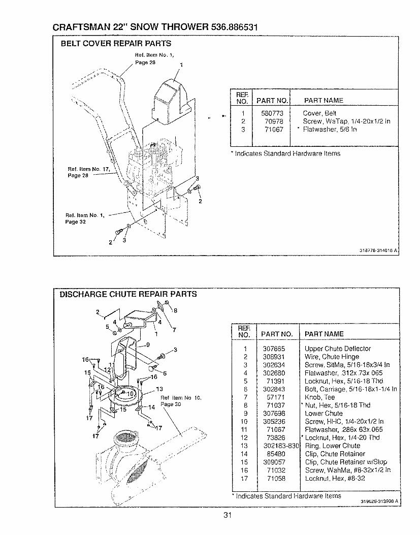
123
PART NO. PART NAME
580773 Cover, Belt70978 Screw, WaTap, 1/4-20xl/2 In71067 " Flatwasher, 5/8 in
Indicates Standard Hardware Items
318778,314018 A
DISCHARGE CHUTE REPAIR PARTS
t7
5
[
Ref Item No 10.
31
REF.NO.
!23456789
10111213I4151617
PART NOo PART NAME
307665308931302634302680
71391302843
5717171037
3076983052367106773826
302183-83085480
3090577103271058
Upper Chute DelfectorWire, Chute HingeScrew, SIIMa, 5/16-18x3/4 InFlatwasher, 312x 73x 065Locknut, Hex, 5/t6-18 ThdBolt, Carriage, 5/16-18x1-1/4 tnKnob, TeeNut, Hex, 5tl 6-18 ThdLower ChuleScrew, HHC, 1/4-20xl/2 InFiatwasher, 286x 63x 065Locknut, Hex, 1/4-20 ThdRing, Lower ChuteClip, Chute RetainerClip, Chute Retainer w/StopScrew, WahMa, #8-32xl/2 InLocknut, Hex, #8-32
Indicates Standard Hardware Items319029*313998 A

CRAFTSMAN 22" SNOW THROWER 536.886531
FRAME COMPONENTS REPAIR PARTS
¸,5¸'i¸¸¸ Ref Item No I,
Page 33
/27
• t /
9
23
INO___:_.!
1 I2 I
34 I56789
1011121314t5
!7
PART NO. PART NAME
583052-854713937110070984
583031-83070978537047107453703
580889
FrameScrew, 5/16-24xl 00 InLocknut, HexWdFl, 5116-24 ThdScrew, WaTap, 5/16-18x3/4 InPanel, BollomScrew, WaTap, 114.20xl/2 InSpring, Idler Traction DriveFlalwasher 53xl 06x 095
Bearing, FlangeShaft Auger Clutch, Assy
5798747380173817
579856710067107250793
Lever, Auger ClutchPin, Spring 165 DIA x 88 LGNut, Push OnCable, ClutchScrew, HHC, 3/8-16x 1-1/4 tnFlatwasherPutley, Idler
RERNO.
18192O212223242526272829303l323334
PART NO,
590579860713607106771035
58O944302623120393
15025809465815403184685798727098573795
57986571038
PART NAME
Locknut, Jam, 318-16 ThdSpool, Cable Auger ClutchScrew, HHC, I/4-20xl-3!4 InFlatwasherNul, Hex Nyl, 1/4-20 ThdCam, Brake ArmBolt, Carriage, 1/4-20x5!8 InFlalwasherLocknut, Hex, tl4.20 ThdRod, Brake ArmPad, BrakeSpring, TensionLever, Idler Arm TractionScrew, HHC, 5/16- ! 8x3/4 InFlatwasher, 328xl 38x 075Bushing, Idler LeverNut, Hex Nyl, 5/16q8 Thd
• tridicates Standard Hardware Items
32
318790-313993 O'

CRAFTSMAN 22" SNOW THROWER 536.886531
ENGINE COMPONENTS REPAIR PARTS
Re! Item!No 1
Page 32
5
9
8
9t0
1t
Rel item No 1Page 34
12
REENO.
t
23456789
101112I314
I
PART NO. PART NAME
326712
30263671060
57985757873357985557985457993257986153715
5812645067771O6371015
Engine, Craltsman, Model NoHSSK50-67326L (See EngineRepair Parts list)Screw, HHC, 5/ _6-18x1-1/4 InLockwasher, Split, 5/16x 58x 08Bracket, Bef/GuideScrew, HHC, 5116-24x5!8 tnWasher, CrankshaftPulley HalfBelt, Traction DriveFiatwasher, ,752x 91x 02Pulley, EngineBe!l, Auger DriveFlalwasher, 375x 1 25x, 104Lockwasher, Split, 38tDScrew, HHC, 3!8-24xl in
33
319026,3139920

CRAFTSMAN 22" SNOW THROWER 536.886531
':DRIVE COMPONENTS REPAIR PARTS
13
1!
26
Ref item No 1,
,//.page 32
22
18
REF,NO.
123456789
I0tl12t314_5 1
PART NO.
579941537037107953818
579937118717105971034
583164583206583155855017381273811
580969
PART NAME
Lever Assembly, Traction ClutchBearing, FlangePin, CotterSpring, RelurnLever, Spring Traction ClulchScrew, HHC, 1/4-20x5/8 InLockwasher, Split, 26x 50x 06Nul, Hex, 1/4-20 ThdDisc, Friction Wheel, T'Zerk, GreaseShaft, Hex TractionBearing Assembly, TrunionFlalwasher• 50xl 00x 06Ring, RelainerFlatwasher 680xl t2x 06
REENO PART NAME
t6t71819202122232425262728
293O
Indicates Standard Hardware Items
PART NO,
49562580970580961580965578962579052
14137098271060
5798585798975817735383O
579893579867
Bearing, RollerKey, SquarePulley, Traction DriveWave WasherFlatwasher, 281xl 00x 063Screw, HHC, 1t4-20x 63Bearing & Retainer AssemblyScrew, WaTap, 5I!6-18xl/2 InLockwasher, Split, 31x 58x 08Washer, SpecialShaft Hex & Sprocket AssemblyHub, Friction WheelWheel, Friction DiscSprocket, 8 Tooth, AssemblyChain, Roller #42
318791-3139{358
34

CRAFTSMAN 22" SNOW THROWER 536.886531
WHEEL ASSEMBLY REPAIR PARTS
REENO.
123456789
101112
/J
PART NO.
580883583012
7383971O35
581730579867
73840578572318504
728573826
239
PART NAME
Shaft, Axle WheelSprocket & AssemblyScrew, HHC, 1/4-20x2-1/4 InNut, Hex Nyl 1/4-20 ThdBdaring, FlangeChain, RollerFtatwasher, 765xl 12x 06Bearing, FlangeTire& Rim, 12x4 lx6Screw, HHC, 1t4-20x1-1/2 InLocknut, Hex, 1/4-20 ThdRing, Retaining
Indicates Standard Hardware Items
35
319037.3t8542C

CRAFTSMAN 22" SNOW THROWER 536.886531
GEAR BOX REPAIR PARTS
19
\ !
9i i18_
!6
11
10
// \9
REF,NO.
123456789
10
PART NO. PART NAME
5127851277
302628302635303008302630
242745030448275
581388
Case, Gear Box R HCase, Gear Box L HScrew, HHC, 1/4-20x3/4 InLocknut, Wd FI, 5/!6-24 ThdNut, Hex Keps, I/4-20 ThdScrew, WaTap, 3/8q 6xl/2 InSeal, OilBearing, FlangeF1atwasher, 752xl 24x 09
Shaft, Auger 22 In
INO. PART NO.
ttt213-14_5
17118
• Indicates Standard Hardware ttems
5127951405
43178750221
583125580295454565
50684301150-830
PART NAME
Gasket, Gear CaseGear, WormKey, Woodruff #61Bearing, F_angeShaft, Worm ImpellerCollar, ThrustPin, SpringBearing, RollImpeller Assembly
3190.343t3996 A
36
CRAFTSMAN 22" SNOW THROWER 536.886531
DECALS
REAR VIEW
AUGER
HOUSING
7
5
6
REE i
4 156 !78 I9
.... t0 J
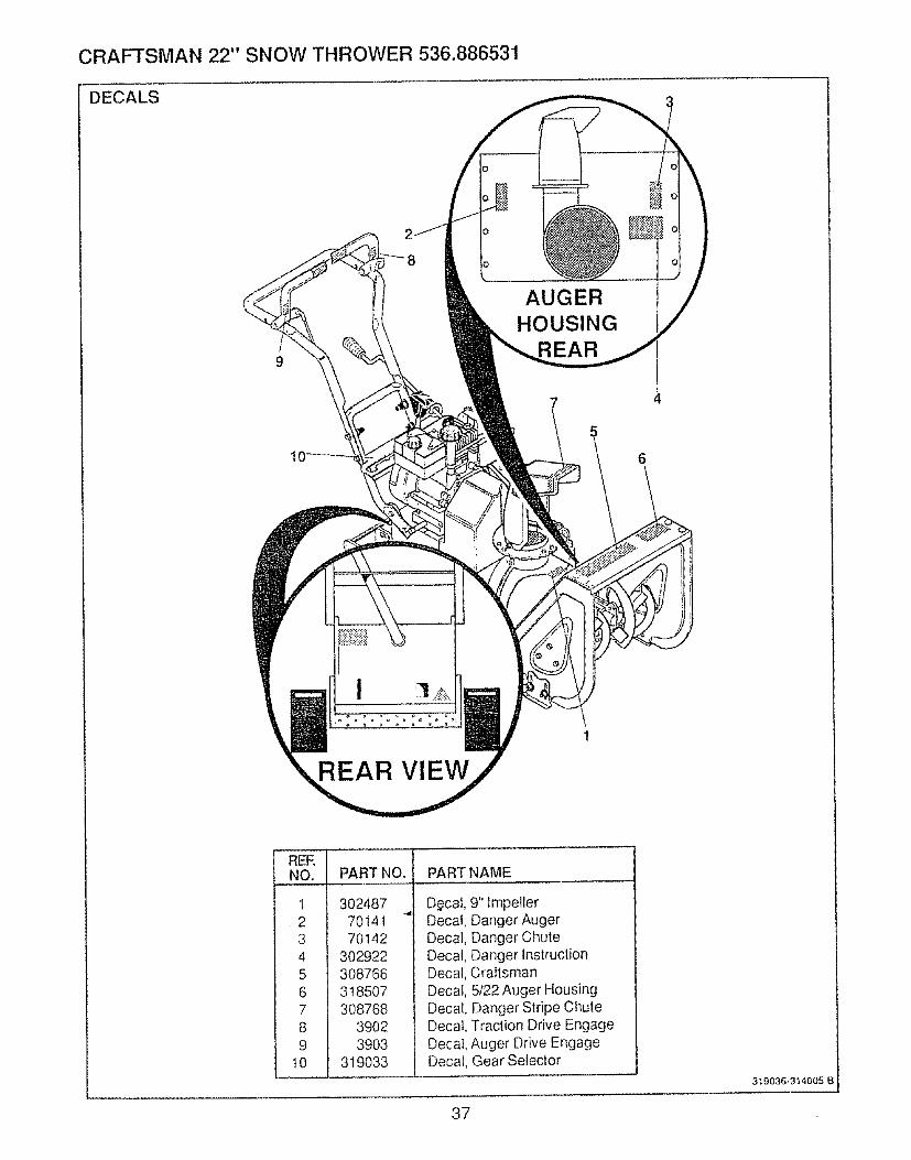
PART NO. PART NAME
3024877014170142
302922308766318507308768
390239O3
319033
D_cal, 9" ImpellerDecal, Danger AugerDecal, Danger ChuteDecal, Danger lnstruclionDecal, CraftsmanDecal, 5/22 Auger HousingDecal, Danger Stripe ChuteDecal, Traction Drive EngageDecal, Auger Drive EngageDecal, Gear Selector
3t9036.314005 B
37

CRAFTSMAN 22" SNOW THROWER 536.886531
SHIFT YOKE REPAIR PARTS
5
Ref.ItemNo.17, i'/i.........." '",',Page 28
4 ----_
3
8/
REF ITEMBLOWER
REF, ITEMENGINE
REENO. PART NO.
1 580769-8302 3026383 738264 3184865 3044386 5808747 5799448 580888-83O9 71111
PART NAME
Rod, Shift-,,,Scrdw, WdFl, 1/4-20x5t8 In
" Locknut, Hex, 1/4-20 ThdNut, HexJam, I/2-!3 ThdKnob, ShiN, t/2-13 ThdPlale, Shift LeverBearing, FlangeSpeed Setect RodLocknut, Hex, 3/8-I6 Thd
*R 'I dtcates Standard Hardware Items
38
319032-319053 B

CRAFTSMAN 4-CYCLE ENGINE MODELNUMBER:143.834012
_301
172
173
38O
338 /
328
219
_1370C/220
421""
/,
390 327
39

CRAFTSMAN 4-CYCLE ENGINE MODEL NUMBER: 143.834012
ReL
No.
245
t4!5161718192O2525A25B26
304O
4O
40
4141
41
4242424345
4648495O6O61626364
64A65697072758O8t82838486899O9293
t00101102;03
tI01t9t20!25
Part
No.
33674B
267273O9683096928277313343151031335
65054831426326O0
t33342t65o139
t30322650561
3474O34535
34535
34537
33562B33563B
33564B
3356733568335892038132875
32610A2724132654_1582974534126
65O76O2854530063
8345650128"27677A34674B27642278973057430590A3059130588A29193
65048861096161108165081565086334443A
610118650872650814
35557"33554A33016A29313C
Part Name
Cylinder Assy (Incl Nos 2, 20. 72 8-72A)Pin, DowetNipple, PipeCap, Oil drainWasher, FlatRod, GovernorLever, GovernorClamp, Governor leverScrew, Hex washer hd, 8-32 x 5/16Spring, ExtensionSeat, OilBaffle, 8lower housingScrew, Fil hd Sems, 8-32 x 1/2Nut, Lock, 8.32Screw, Hex washer hd Dudok, 1/4-20x 5/8Crankshaft AssyPiston, Pin 8" Ring Assy (Std.) (InclNos 41, 42 Et 43)Piston. Pin 8" Ring Assy (.010 over-
size) (Incl. Nos. 41, 42 El- 43)Piston, Pin 8- Ring Assy (.020 over..size) (fncl. Nos 41, 42 8- 43)Piston 8- Pin Assy {Std ) (lncl No 43)Piston 8" Pin Assy (0t0 oversize)
i(Incl. No 43)Piston 8 Pin Assy. (020 oversize)(Inei. No 43)Ring Set, Piston (Std.)Ring Set. Piston ( 010 oversize)Ring Set, Piston ( 020 oversize)Ring, Piston pin retainingRod Assy , Connecting (tnct. Nos 468" 49)Bolt, Connecting rodLifter, ValveDipper, OitCamshaft (Compression Release)Extension, Blower housingBracket, Grommet mountingScrew, Pan hd. taptite, 8-32 x 3/8Grommet, PlasticScrew, Torx T-30 Hex washer hdSems, 1/4-20 x 1/2Washer, FlatScrew, Hex hd Seres, 10-24 x I/2Gasket, Cylinder coverCover, Cylinder (Incl Nos 75 8- 80}Plug, Pipe. 1/4-18Seal, OilShaft, Mechanical governorWasher, FlatGear, Governor (Inci No 8!)Spool, GovernerRing, RetainingScrew, Hex hd Seres. t/4-20 x 1-l/4Key, FlywheelFlywheel (w/ring gearlWasher, BellevilleNut, FiywheelSol_d State AssyCover, Spark plugStud, Solid state mountingScrew, Torx Tq5 hex washer hdSeres. 10-24 x 1Wire, GroundGasket, Cylinder headHead, Cytinder(lnct No 131)Valve. Exhausl (Std } (lncI No 15D
ReL Part
No. No.
125 293t5C
126 32644A126 32645A
127 650691129 650818
6021A,650694A
353953167231673
"27234A2766631410
I 414635350
65012829752
6201650870
34583"26756
335913269833858A
203 31342204 650649206 510973215 35440219 34582220 354,38222 28820223 650664224 "33673A260 35656A261 29212267 34212268 30200
272 650735
273 33333274 "33670A275 35771277 650327285 34694287 650884291 30705292 26460298 650665
300 35584301 36355305 35564307 35499308 35539310 355563!3 34080327 35392328 35593
130t31 ,.t35t50t51169170171172173174178181182183184185186200
Part Name
Valve, Exhaust (!/32" oversize) (Incl --No 151)Valve, Intake (Std,) (tncl No 151)Valve, Intake (1/32" oversize) (lnd No151}Washer, FlatScrew, Special hex hd. 5/16-18 xl-!/2Screw, Hex flange hd., 5/16-18 x 1-1/2Screw, Hex flange hd., 5/16-18 x 2Spark Plug, ResistorSpring, ValveCap, Valve springGasket, Valve coverBody, Valve coverElement, VMve bodyCover, BreatherTube, BreatherScrew, Hex hd. Seres, 10-24 x 1/2Nut 8- Lockwasher, I/4-28Screw, Hex hd, I/4-28 x 7/8Screw, Hex hal, 1/4.28 x 1-11/16Bracket, ChokeGasket, CarburetorPipe, IntakeLink, Governor to throttleControl Assy., Bracket (lncL Nos..25A, 25B, 203, 204 _ 206)Spring, CompressionScrew, Fil. hal, 5-40 x 7/t6Terminal AssyKnob, Speed controlRod, ChokeKnob, Choke controlScrew, Fil hd Sems, 10-32 x 1/2Screw, FiL hd Sems, 1/4.20x lq9/32Gasket. IntakeHousing, BlowerScrew, Hex hd. Seres, t/4-28 x 7/16Bracket, Hold downScrew, Hex washer hd self-tap Seres,10_24 x 9/t6Screw, Hex hd Seres, tapthe, 10-24 x3/8Bracket, Carburetor coverGasket, ExhaustMuffler {lncl No 274)Screw, Fil hd. Seres, I/4-20 x 2-1/2Cup, StarterScrew, Hex washer hd.. 8-32 x 1/2Line, FuelClamp, Fuel lineScrew, Hex washer hd serf-tap Sems,1/4-15 x 7/8Tank Assy, Fuel (Incl Nos 292 8- 301)Cap, Fuel tankTube Assy, Oii fill"O" RingClip, Oil flitDipstickSpacer, Flywheel keyPIug. StarterKey. ignition
"Indicates Parts Included inGasket SaL Ref No 400
40

CRAFTSMAN 4-CYCL.E ENGINE MODEL NUMBER:143.834012
Ref Part PartNo No, No. Part Name
329330335338340342
342A345350351352353
370B370C370D380390
6109733528535072
6502573624730063
65067533344
57068232180C35883
650884341443528235878
632107A59O648
Part Name
Terminal AssyWire. GroundCover, CarbureTorScrew, Pan hd Seres. 8-32 x5/16Plate. Fuel tankScrew. Torx T-30 Hex washer hdSeres, t/4-20 x t/2Washer. F]a_Baffie, Hea!Primer AssyLine. PrimerExtension. BaffleScrew, Hex washe_ I-_d 8.32 x 1 ZDecal PrimerDecal, ChokeDecal. WarningCarburetor (Incl No 184}Starter. Rewind
Ref..
Noo
3958
400421
33683 B730226
Electric Statler Kit 14388.933 (Op-tional) Sold as accessoryGasket Set (tncl items marked *)Oil. 4-Cycle - SAE 5W30 (quart}
RPM Settings:Low Speed; !550 - 1850High Speed: 3550 - ,3850
"Indicates Parts Included inGasket SeT, Ref No 400
tin original production the speed con-trol assembly is riveted to the blowerhousing baffle, Replacement speedcontrol assembly includes screws andnuts for mounting Replacement bafflel_as threaded holes
41
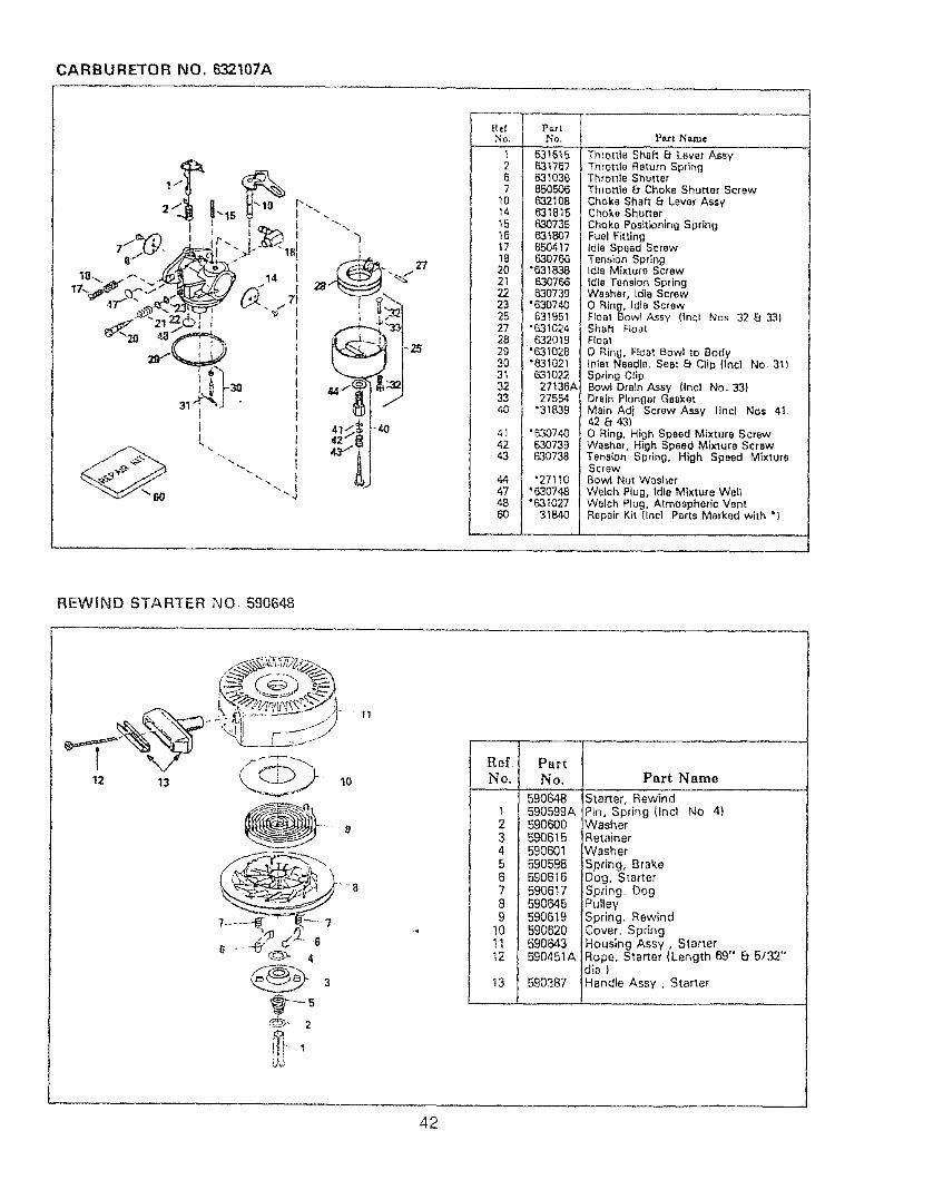
CARBURETOR NO. 632t07A
-j.
I 2! 631757!I 6| 63_036I] 71 650506 J! _o| 6321081i _4| 63_B15 ][ _5| 630735 1! _6! e3_B07 ]
! _a/ _o7_ II 20| .e3_83a t
I 22 | 830739 lI 23 | "630740 1I 251 63t95_ j[ 27 | "631024 t[ 2B |. &32019 II 29 |"'631028 Jl 30| "_021 !i 3_| _o22 |i 32 | 27136A l
33 | 27554 ti _| -3_B39II _, | ._o74o !
42 | 830739 I
' _[ 63o7* I
47 | '630748 J
Part Name
Throttle Shaft 8" Lever AssyThrottle Return SpringThrome ShutterThmtHe Et Choke Shutter Screw
Choke Shaft 8 Lever A_yChoke ShutterChoke Poeitionlng SpringFuel FittingIdle Speed ScrewTension SpringIdleMixture Screw
idle Tension SpdngWasher, Idle ScrewO Ring, Idle ScrewFIoat Bow] Assy (lnci Nos 32 E_ ,3,3)Shah FloatFlea1
O Ring, Roar Bow] to BodyInlet Needle, Seat _t Clip {Inci No 311Spring ClipBowl Drain Assy {incl NO 33)Drain Plunger GasketMain Adj Screw Assy tlncl Nos 41,42 8' 43}
0 Ring, High Speed Mixture ScrewWasher, High Speed Mixture ScrewTension Spring, High Speed MixtureScrewBowi Nut Washer
Welch Plug, idle Mixture WellWelch Plug. Atmospheric VentRepair Kit {Incl Parts Marked with *}
REWIND STARTER NO 590648
12 13 10
....... 9
4
11
'"'""'Rel, Part
} No, I No,
l 159o_l 1 t 590599Al 2 l 59o_0] 3 I 590615l 4 [ 590601I 5 ) 590598/ 6 f _oe_/ 7 1 69o6_7I a I 590_45| 9 I 590619J 10 / 590620) _ 1 590643
l t2 t 590451A
Part Name
|Starter, RewindPin, Spring (Incl No 4)
WasherRetainerWasherSpring, BrakeDog, Starter
Spring. bogPulleySpring, RewindCover. SpringHousing Assy, StarterRope, Starter (Length 69" B 5/32"dia }
Handle Assy , Starter
42

NOTES
43
OWNER'SANUAL
MODEL NO.536.886531
HOW TO ORDERREPAIR PARTS
C5 HORSEPOWER22" DUAL STAGESNOW THROWEROptional e_ectric start
®
Each SNOW THROWER has its own MODELNUMBER found on the engine mount frame
Each ENGINE has its own MODEL NUMBERfound on the BLOWER HOUSING
Always mention these MODEL NUMBERS whenrequesting service or Repair Parts for your SNOWTHROWER
All parls may be ordered through Sears, Roebuckand Company Service Centers and most RetailStores
WHEN ORDERING REPAIR PARTS, ALWAYSGIVE THE FOLLOWING INFORMATION:
' PRODUCT - "SNOW THROWER"
• MODEL NUMBER - 536.,886530
* ENGINE MODEL NUMBER - 1438340t2
* PART NUMBER
* PART DESCRIPTION
"Your Sears merchandise has added value when youconsider that Sears has service units nationwide staffedwilh Sears trained technicians Professional techniciansspecifically trained on Sears products, having the parts,tools and equipment to insure that we meet our pledgeto you_ we service what we sell -
SEARS, ROEBUCK AND COn, Hoffman Estates, IL 60195325951 08/05192 Printed in U S A