owner's manual - stamina...
TRANSCRIPT
35-1400ASTAMINA PRODUCTS
MADE IN CHINA
Product May Vary SlightlyFrom Pictured.
2005, 09
Exercise can present a healthrisk. Consult a physicianbefore beginning any exerciseprogram with this equipment.If you feel faint or dizzy,immediately discontinue useof this equipment. Seriousbodily injury can occur if thisequipment is not assembledand used correctly. Seriousbodily injury can also occur ifall instructions are notfollowed. Keep others andpets away from equipmentwhen in use. Always makesure all bolts and nuts aretightened prior to each use.Follow all safety instructions inthis manual.
When calling for parts orservice, please specify thefollowing number.
WARNING
CAUTION:Weight on this product should not exceed 250 lbs.
2040 N. Alliance, Springfield, MO 65803Customer Service Number
1 (800) 375-7520www.staminaproducts.com
This Product is Produced Exclusively by
Owner's Manual
2005 Stamina Products, Inc.
TABLE OF CONTENTSPage Page
SAFETY INSTRUCTIONS
To reduce the risk of serious injury, read the following Safety Instructions beforeusing the 1400 AIR ROWER.
WARNING:
Before starting any exercise or conditioning program you should consult with your personalphysician to see if you require a complete physical exam. This is especially important if youare over the age of 35, have never exercised before, are pregnant, or suffer from anyillness. READ AND FOLLOW THE SAFETY PRECAUTIONS. FAILURE TO FOLLOWTHESE INSTRUCTIONS CAN RESULT IN SERIOUS BODILY INJURY.
WARNING:
1.2.
3.
4.
5.6.7.
8.9.
10.11.
12.
13.14.15.
2
Read all warnings posted on the 1400 AIR ROWER.Read this Owner's Manual and follow it carefully before using the 1400 AIR ROWER. Make surethat it is properly assembled and tightened before use.Keep children away from the 1400 AIR ROWER. Do not allow children to use or play on the 1400AIR ROWER. Keep children and pets away from the 1400 AIR ROWER when it is in use.Set up and operate the 1400 AIR ROWER on a solid level surface. Do not position the 1400 AIRROWER on loose rugs or uneven surfaces.Inspect the 1400 AIR ROWER for worn or loose components prior to use.Tighten/replace any loose or worn components prior to using the 1400 AIR ROWER.Consult a physician prior to commencing an exercise program. If, at any time during exercise, youfeel faint, dizzy, or experience pain, stop and consult your physician.Follow your physician's recommendations in developing your own personal fitness program.Always choose the workout which best fits your physical strength and flexibility level. Know yourlimits and train within them. Always use common sense when exercising.Do not wear loose or dangling clothing while using the 1400 AIR ROWER.Never exercise in bare feet or socks; always wear correct footwear, such as running, walking, orcrosstraining shoes. Be sure that they fit well, provide foot support and feature non-skid rubbersoles.Be careful to maintain your balance while using, mounting, dismounting, or assembling the 1400AIR ROWER, loss of balance may result in a fall and serious bodily injury.The 1400 AIR ROWER should not be used by persons weighing over 250 pounds.The 1400 AIR ROWER should be used by only one person at a time.The 1400 AIR ROWER is for consumer use only. It is not for use in public or semipublic facilities.
Conditioning Guidelines 11Warm-up and Cool-Down 12Warranty 13Product Parts Drawing 14Parts List 15Notes 17Fax/Mail Ordering Form 18
Safety Instructions 2Before You Begin 4Hardware Identification Chart 5Assembly Instructions 6Using The Electronics Meter 9Storage 10Maintenance 10
THANK YOU FOR PURCHASING THE1400 AIR ROWER
To help you get started, we have pre-assembled most of your1400 AIR ROWER at the factory with the exception
of those few parts left unassembled for shipping purposes.Simply follow the few assembly instructions set forth in this manual.
Within a few minutes you will be getting your body into shape and on yourway to achieving a happier and healthier lifestyle.
Should you have any questions,please call our Customer Service Department toll-free number,
1 (800) 375-7520Monday - Friday, 8:00 A.M. - 5:00 P.M., Central Time.
CALL US FIRST
3
BEFORE YOU BEGIN
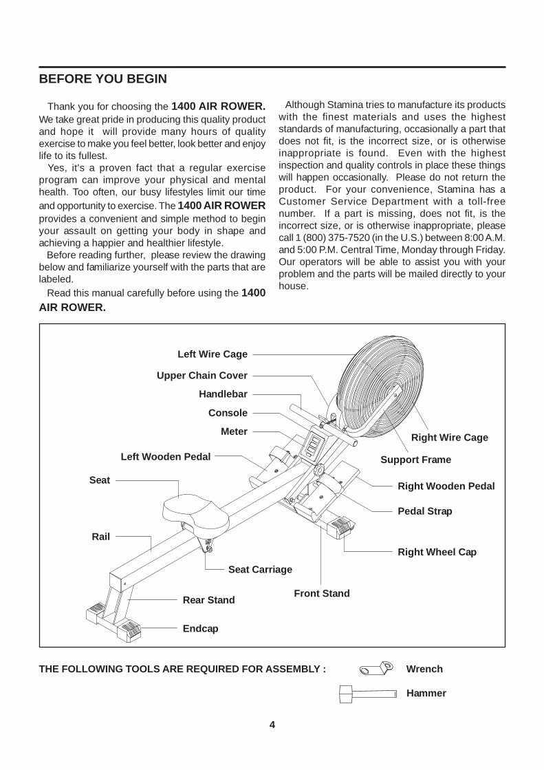
Thank you for choosing the 1400 AIR ROWER.We take great pride in producing this quality productand hope it will provide many hours of qualityexercise to make you feel better, look better and enjoylife to its fullest. Yes, it's a proven fact that a regular exerciseprogram can improve your physical and mentalhealth. Too often, our busy lifestyles limit our timeand opportunity to exercise. The 1400 AIR ROWERprovides a convenient and simple method to beginyour assault on getting your body in shape andachieving a happier and healthier lifestyle. Before reading further, please review the drawingbelow and familiarize yourself with the parts that arelabeled. Read this manual carefully before using the 1400AIR ROWER.
Although Stamina tries to manufacture its productswith the finest materials and uses the higheststandards of manufacturing, occasionally a part thatdoes not fit, is the incorrect size, or is otherwiseinappropriate is found. Even with the highestinspection and quality controls in place these thingswill happen occasionally. Please do not return theproduct. For your convenience, Stamina has aCustomer Service Department with a toll-freenumber. If a part is missing, does not fit, is theincorrect size, or is otherwise inappropriate, pleasecall 1 (800) 375-7520 (in the U.S.) between 8:00 A.M.and 5:00 P.M. Central Time, Monday through Friday.Our operators will be able to assist you with yourproblem and the parts will be mailed directly to yourhouse.
4
THE FOLLOWING TOOLS ARE REQUIRED FOR ASSEMBLY : Wrench
Hammer
Left Wire Cage
Handlebar
Upper Chain Cover
Meter
Console
Seat
Rail
Seat Carriage
Rear Stand
Endcap
Right Wheel Cap
Right Wooden Pedal
Pedal Strap
Support Frame
Front Stand
Right Wire Cage
Left Wooden Pedal
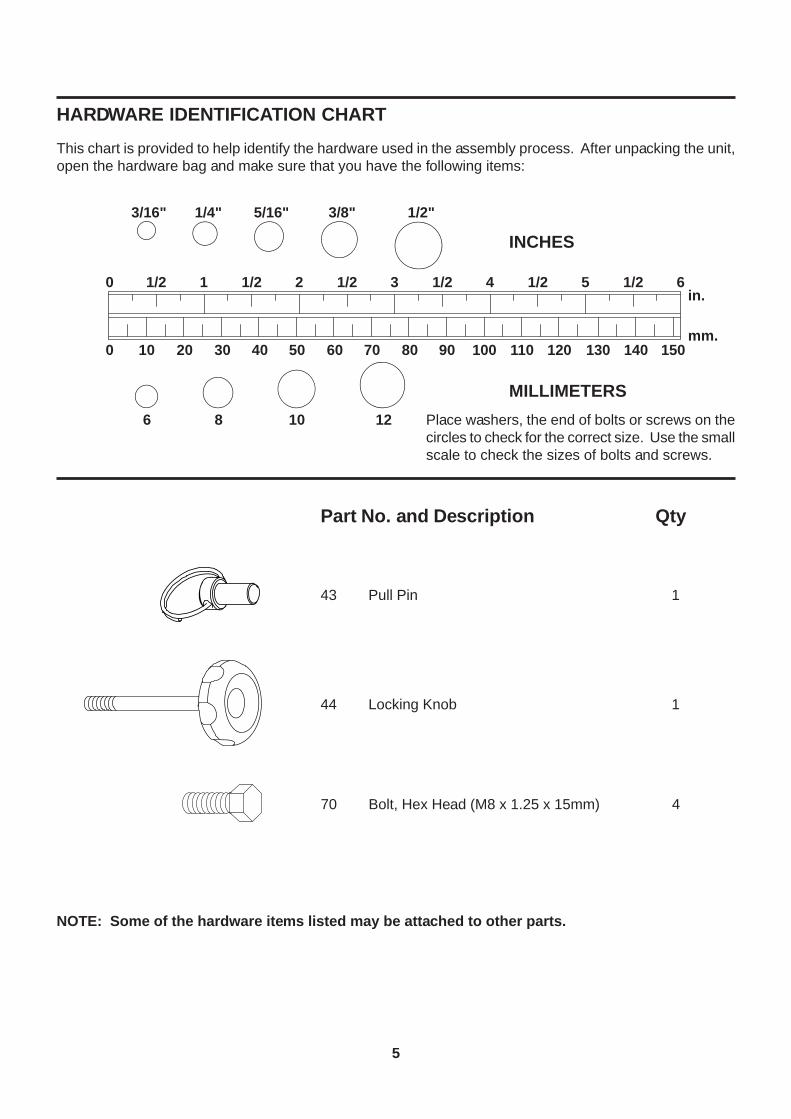
70 Bolt, Hex Head (M8 x 1.25 x 15mm) 4
5
Part No. and Description Qty
mm.
in.
INCHES
MILLIMETERS
11/20 21/2 31/2 41/2 51/2 61/2
0 10 20 30 40 50 60 70 80 90 100 110 120 130 140 150
6 8 10 12
3/16" 5/16" 1/2"3/8"1/4"
HARDWARE IDENTIFICATION CHART
Place washers, the end of bolts or screws on thecircles to check for the correct size. Use the smallscale to check the sizes of bolts and screws.
This chart is provided to help identify the hardware used in the assembly process. After unpacking the unit,open the hardware bag and make sure that you have the following items:
NOTE: Some of the hardware items listed may be attached to other parts.
43 Pull Pin 1
44 Locking Knob 1
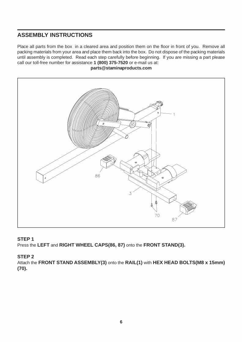
Place all parts from the box in a cleared area and position them on the floor in front of you. Remove allpacking materials from your area and place them back into the box. Do not dispose of the packing materialsuntil assembly is completed. Read each step carefully before beginning. If you are missing a part pleasecall our toll-free number for assistance 1 (800) 375-7520 or e-mail us at:
ASSEMBLY INSTRUCTIONS
6
STEP 1Press the LEFT and RIGHT WHEEL CAPS(86, 87) onto the FRONT STAND(3).
STEP 2Attach the FRONT STAND ASSEMBLY(3) onto the RAIL(1) with HEX HEAD BOLTS(M8 x 15mm)(70).

ASSEMBLY INSTRUCTIONS
7
STEP 3Slide the SEAT(54) onto the RAIL(1). Attach the REAR STAND(2) onto the RAIL(1) with HEX HEADBOLTS(M8 x 15mm)(70).NOTE:
STEP 4Remove the LOCKING KNOB(44) from the SUPPORT FRAME(4). Remove the PULL PIN(43) fromthe RAIL(1). Unfold the FAN ASSEMBLY by swinging the SUPPORT FRAME(4) toward the front.
Refer to the inset drawing. If it is difficult to slide the SEAT(54) onto the RAIL(1), turn theNYLOCK NUT(M6)(75) located on the SEAT CARRIAGE(55) counter-clockwise to adjustthe position of the Roller lower.If the SEAT(54) rocks on the RAIL(1), turn the NYLOCK NUT(M6)(75) located on the SEATCARRIAGE(55) clockwise to tighten the Roller.
1.
2.
Roller
Fan Assembly
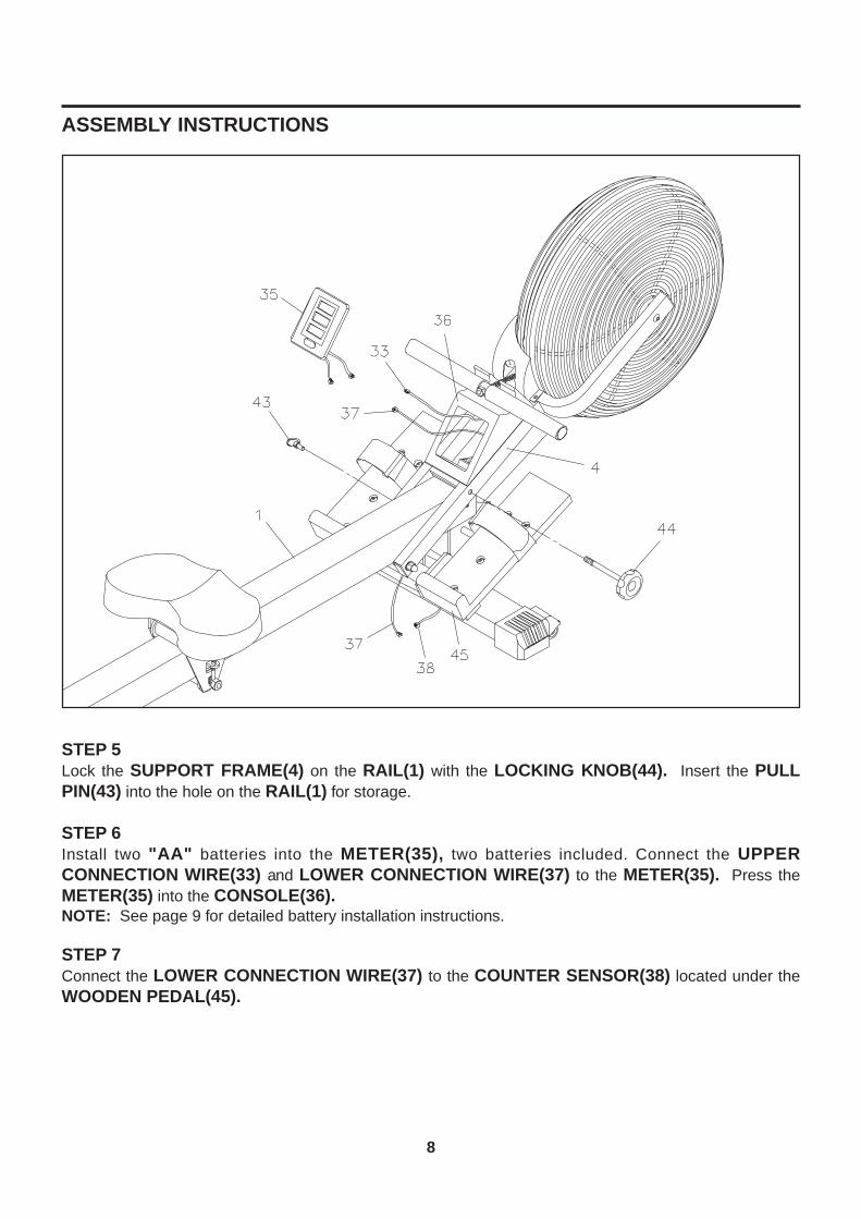
ASSEMBLY INSTRUCTIONS
8
STEP 5Lock the SUPPORT FRAME(4) on the RAIL(1) with the LOCKING KNOB(44). Insert the PULLPIN(43) into the hole on the RAIL(1) for storage.
STEP 6Install two "AA" batteries into the METER(35), two batteries included. Connect the UPPERCONNECTION WIRE(33) and LOWER CONNECTION WIRE(37) to the METER(35). Press theMETER(35) into the CONSOLE(36).NOTE: See page 9 for detailed battery installation instructions.
STEP 7Connect the LOWER CONNECTION WIRE(37) to the COUNTER SENSOR(38) located under theWOODEN PEDAL(45).
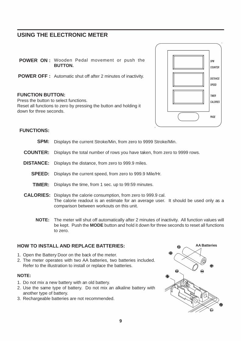
USING THE ELECTRONIC METER
FUNCTION BUTTON:Press the button to select functions.Reset all functions to zero by pressing the button and holding itdown for three seconds.
Wooden Pedal movement or push theBUTTON.
Automatic shut off after 2 minutes of inactivity.
POWER ON :
POWER OFF :
Displays the current Stroke/Min, from zero to 9999 Stroke/Min.
Displays the total number of rows you have taken, from zero to 9999 rows.
Displays the distance, from zero to 999.9 miles.
Displays the current speed, from zero to 999.9 Mile/Hr.
Displays the time, from 1 sec. up to 99:59 minutes.
Displays the calorie consumption, from zero to 999.9 cal.The calorie readout is an estimate for an average user. It should be used only as acomparison between workouts on this unit.
FUNCTIONS:
COUNTER:
DISTANCE:
SPEED:
TIMER:
CALORIES:
SPM:
NOTE: The meter will shut off automatically after 2 minutes of inactivity. All function values willbe kept. Push the MODE button and hold it down for three seconds to reset all functionsto zero.
HOW TO INSTALL AND REPLACE BATTERIES:
1.2.
Do not mix a new battery with an old battery.Use the same type of battery. Do not mix an alkaline battery withanother type of battery.Rechargeable batteries are not recommended.
1.2.
3.
NOTE:
Open the Battery Door on the back of the meter.The meter operates with two AA batteries, two batteries included.Refer to the illustration to install or replace the batteries.
9
AA Batteries
1010
Sit on the SEAT(54) and pull on the HANDLEBAR(27) to verify that the Fan System provides resistanceand the Seat travel is smooth and stable.Clean the roller tracks on the RAIL(1) with an absorbent cloth.It is the sole responsibility of the user/owner to ensure that regular maintenance is performed.Verify that all nuts and bolts are present and properly tightened. Replace missing nuts and bolts. Tightenloose nuts and bolts.Worn or damaged components shall be replaced immediately or the 1400 AIR ROWER removed fromservice until repair is made.Only Stamina Products supplied components shall be used to maintain/repair the 1400 AIR ROWER.Keep your 1400 AIR ROWER clean by wiping with an absorbent cloth after use.
1.
2.3.4.
5.
6.7.
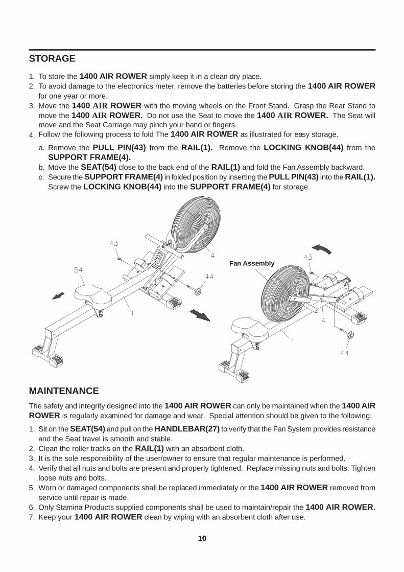
STORAGE
To store the 1400 AIR ROWER simply keep it in a clean dry place.To avoid damage to the electronics meter, remove the batteries before storing the 1400 AIR ROWERfor one year or more.Move the 1400 AIR ROWER with the moving wheels on the Front Stand. Grasp the Rear Stand tomove the 1400 AIR ROWER. Do not use the Seat to move the 1400 AIR ROWER. The Seat willmove and the Seat Carriage may pinch your hand or fingers.Follow the following process to fold The 1400 AIR ROWER as illustrated for easy storage.
1.2.
3.
4.
Remove the PULL PIN(43) from the RAIL(1). Remove the LOCKING KNOB(44) from theSUPPORT FRAME(4).Move the SEAT(54) close to the back end of the RAIL(1) and fold the Fan Assembly backward.Secure the SUPPORT FRAME(4) in folded position by inserting the PULL PIN(43) into the RAIL(1).Screw the LOCKING KNOB(44) into the SUPPORT FRAME(4) for storage.
a.
b.c.
MAINTENANCEThe safety and integrity designed into the 1400 AIR ROWER can only be maintained when the 1400 AIRROWER is regularly examined for damage and wear. Special attention should be given to the following:
Fan Assembly
How you begin your exercise program depends on your physical condition. If you have been inactive forseveral years, or are severely overweight, you must start slowly and increase your time on the 1400 AIRROWER gradually: a few minutes per workout.
Initially, you may be able to exercise only for a few minutes in your target zone, however, your aerobicfitness will improve over the next six to eight weeks. Don't be discouraged if it takes longer. It's important towork at your own pace. Ultimately, you'll be able to exercise continuously for 30 minutes. The better youraerobic fitness, the harder you will have to work to stay in your target zone. Please remember theseessentials:
Have your doctor review your training and diet programs to advise you of a workout routine youshould adopt.
Begin your training program slowly with realistic goals that have been set by you and your doctor.
Monitor your pulse frequently. Establish your target heart rate base on your age and condition.
Set up your 1400 AIR ROWER on a flat, even surface at least 3 feet from walls and furniture.
CONDITIONING GUIDELINES
11
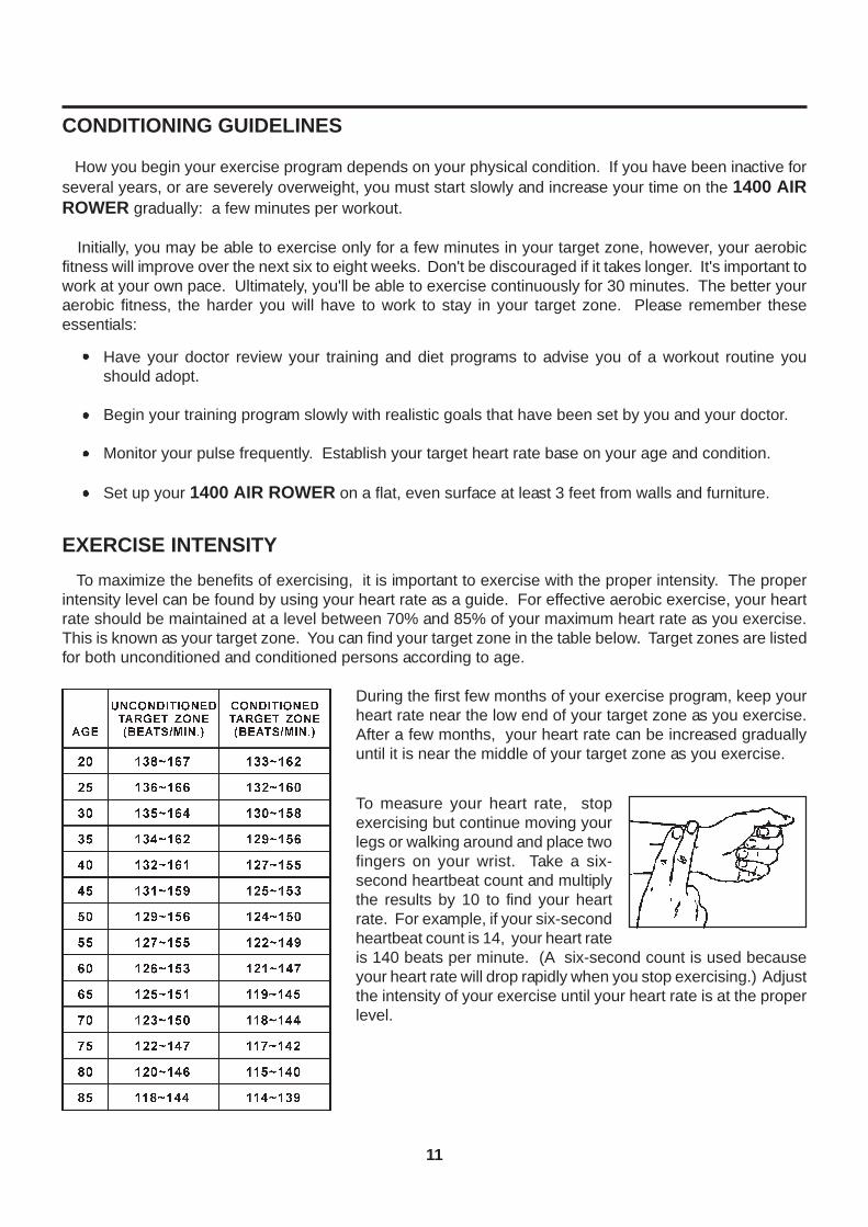
To maximize the benefits of exercising, it is important to exercise with the proper intensity. The properintensity level can be found by using your heart rate as a guide. For effective aerobic exercise, your heartrate should be maintained at a level between 70% and 85% of your maximum heart rate as you exercise.This is known as your target zone. You can find your target zone in the table below. Target zones are listedfor both unconditioned and conditioned persons according to age.
EXERCISE INTENSITY
During the first few months of your exercise program, keep yourheart rate near the low end of your target zone as you exercise.After a few months, your heart rate can be increased graduallyuntil it is near the middle of your target zone as you exercise.
To measure your heart rate, stopexercising but continue moving yourlegs or walking around and place twofingers on your wrist. Take a six-second heartbeat count and multiplythe results by 10 to find your heartrate. For example, if your six-secondheartbeat count is 14, your heart rateis 140 beats per minute. (A six-second count is used becauseyour heart rate will drop rapidly when you stop exercising.) Adjustthe intensity of your exercise until your heart rate is at the properlevel.
12
WARM-UP and COOL-DOWN
Warm-up The purpose of warming up is to prepare your body for exercise and to minimize injuries. Warmup for two to five minutes before strength-training or aerobic exercising. Perform activities that raise yourheart rate and warm the working muscles. Activities may include brisk walking, jogging, jumping jacks, jumprope, and running in place
Stretching Stretching while your muscles are warm after a proper warm-up and again after your strengthor aerobic training session is very important. Muscles stretch more easily at these times because of theirelevated temperature, which greatly reduces the risk of injury. Stretches should be held for 15 to 30 seconds.Do not bounce.
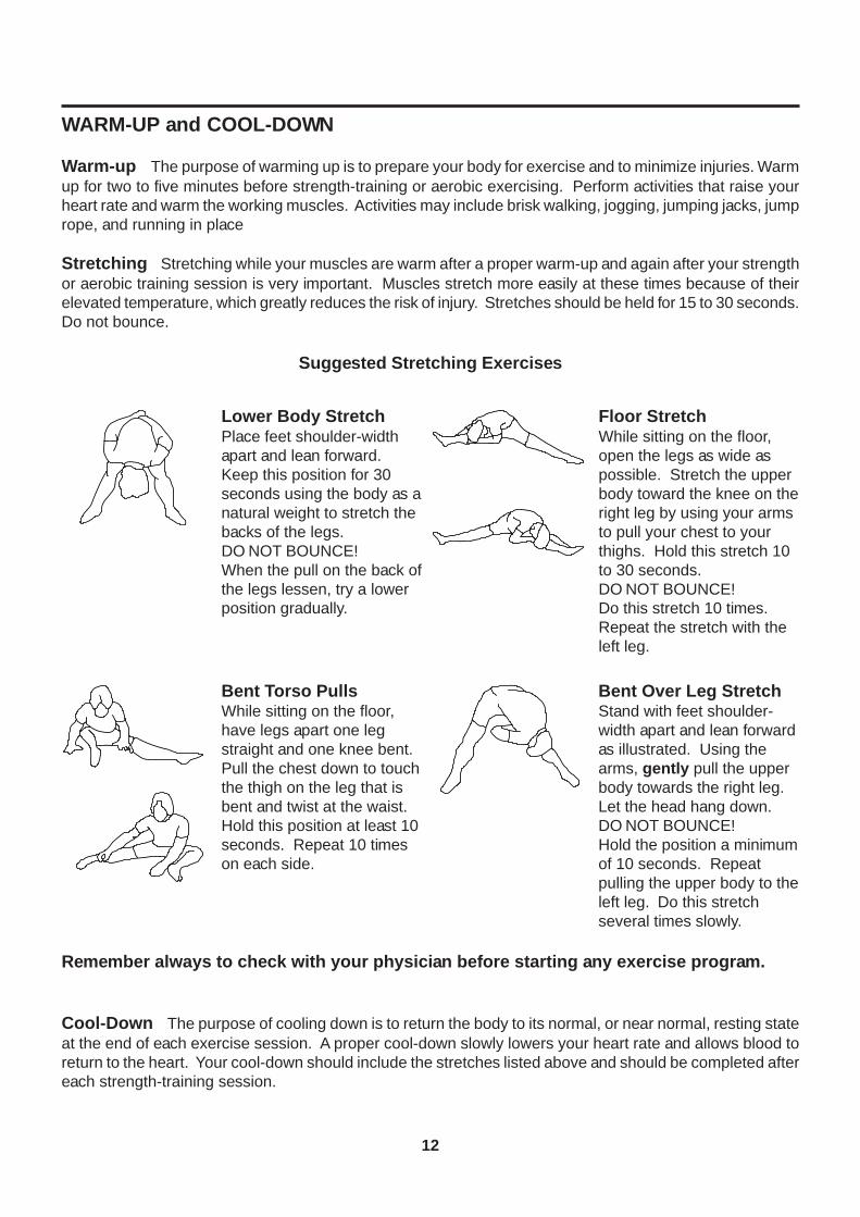
Suggested Stretching Exercises
Remember always to check with your physician before starting any exercise program.
Cool-Down The purpose of cooling down is to return the body to its normal, or near normal, resting stateat the end of each exercise session. A proper cool-down slowly lowers your heart rate and allows blood toreturn to the heart. Your cool-down should include the stretches listed above and should be completed aftereach strength-training session.
Lower Body StretchPlace feet shoulder-widthapart and lean forward.Keep this position for 30seconds using the body as anatural weight to stretch thebacks of the legs.DO NOT BOUNCE!When the pull on the back ofthe legs lessen, try a lowerposition gradually.
Floor StretchWhile sitting on the floor,open the legs as wide aspossible. Stretch the upperbody toward the knee on theright leg by using your armsto pull your chest to yourthighs. Hold this stretch 10to 30 seconds.DO NOT BOUNCE!Do this stretch 10 times.Repeat the stretch with theleft leg.
Bent Over Leg StretchStand with feet shoulder-width apart and lean forwardas illustrated. Using thearms, gently pull the upperbody towards the right leg.Let the head hang down.DO NOT BOUNCE!Hold the position a minimumof 10 seconds. Repeatpulling the upper body to theleft leg. Do this stretchseveral times slowly.
Bent Torso PullsWhile sitting on the floor,have legs apart one legstraight and one knee bent.Pull the chest down to touchthe thigh on the leg that isbent and twist at the waist.Hold this position at least 10seconds. Repeat 10 timeson each side.
Stamina Products, Inc. warrants that this product will be free from defects in materials and workmanshipunder normal use, service and proper operation for a period of 90 days on the parts and three years on theframe from the date of the original purchase from an authorized retailer. THIS WARRANTY SHALL NOTAPPLY TO ANY PRODUCT WHICH HAS BEEN SUBJECT TO COMMERCIAL USE, ABUSE, MISUSE,ALTERATION OF ANY TYPE OR CAUSE OR TO ANY DEFECT OR DAMAGE CAUSED BY REPAIR,REPLACEMENT, SUBSTITUTION OR USE WITH PARTS OTHER THAN PARTS PROVIDED BY STAMINAPRODUCTS, INC. Commercial use includes use of the product in athletic clubs, health clubs, spas,gymnasiums, exercise facilities, and other public or semipublic facilities whether or not the product's use isin furtherance of a profit making enterprise, and all other use which is not for personal, family, or householdpurposes.
To implement this limited warranty, send a written notice stating your name, date, and place of purchase anda brief description of the defect along with your receipt to Stamina Products, Inc. P.O. Box 1071, SpringfieldMissouri, USA, 65801-1071 or call us at 1 (800) 375-7520. If the defect is covered under this limitedwarranty, you will be requested to return the product or part to us for free repair or replacement at our option.NO ACTION FOR BREACH OF THIS LIMITED WARRANTY MAY BE COMMENCED MORE THAN ONE(1) YEAR AFTER THE DATE THE ALLEGED BREACH WAS OR SHOULD HAVE BEEN DISCOVERED.NO ACTION FOR BREACH OF ANY IMPLIED WARRANTY MAY BE COMMENCED MORE THAN ONE(1) YEAR AFTER DELIVERY OF THE PRODUCT TO THE PURCHASER. This limited warranty is nottransferable. IF ANY PART OF THE PRODUCT IS NOT IN COMPLIANCE WITH THIS LIMITEDWARRANTY OR ANY IMPLIED WARRANTY, THE REMEDY OF REPAIR OR REPLACEMENT IS THEEXCLUSIVE REMEDY AVAILABLE TO YOU. In the event that the purchaser makes any claim under thislimited warranty or any implied warranty, the Warrantor reserves the right to require the product to be returnedfor inspection, at the purchaser's expense, to the Warrantor's premises in Springfield, Missouri. Return ofthe enclosed warranty registration card is not required for warranty coverage, but is merely a way ofestablishing the date and place of purchase.
Stamina Products, Inc. SHALL NOT BE LIABLE FOR THE LOSS OF USE OF ANY PRODUCT, LOSS OFTIME, INCONVENIENCE, COMMERCIAL LOSS OR ANY OTHER INDIRECT, CONSEQUENTIAL,SPECIAL OR INCIDENTAL DAMAGES DUE TO BREACH OF THE ABOVE WARRANTY OR ANY IMPLIEDWARRANTY.
This limited warranty is the only written or express warranty given by Stamina Products, Inc. This warrantygives you specific legal rights, and you may also have other legal rights which vary from state to state.ANY OTHER RIGHT WHICH YOU MAY HAVE, INCLUDING ANY IMPLIED WARRANTY ORMERCHANTABILITY OR FITNESS FOR A PARTICULAR PURPOSE, IS LIMITED IN DURATION TO THEDURATION OF THIS WARRANTY.
The laws in some jurisdictions restrict the rights of manufacturers and distributors of consumer goods todisclaim or limit implied warranties and consequential and incidental damages with respect thereto. If anysuch law is found to be applicable, the foregoing disclaimers and limitations of and on implied warranties andconsequential and incidental damages with respect thereto shall be disregarded and shall be deemed not tohave been made to the extent necessary to comply with such legal restriction.
13
WARRANTY
LIMITED WARRANTYMODEL 35-1400A
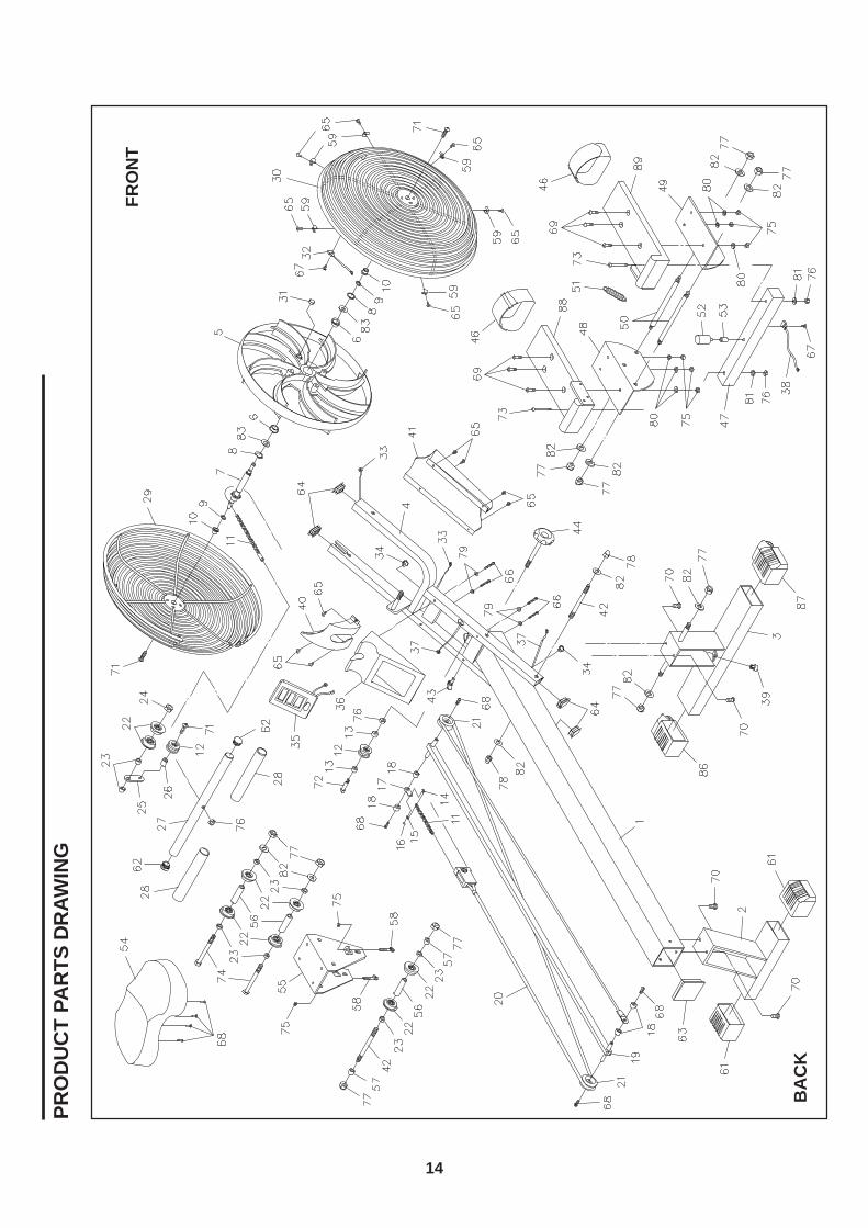
PRO
DU
CT
PAR
TS D
RAW
ING
FRO
NT
BA
CK
14
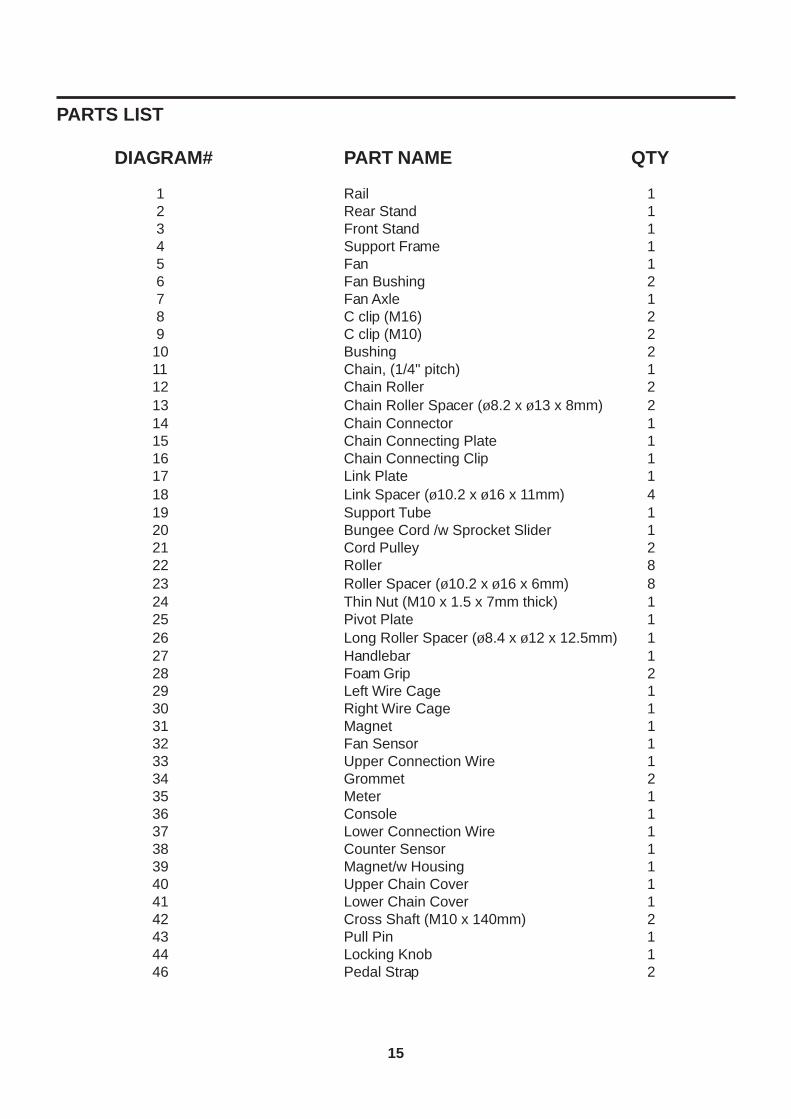
PARTS LIST
DIAGRAM# PART NAME QTY
15
1 Rail 1 2 Rear Stand 1 3 Front Stand 1 4 Support Frame 1 5 Fan 1 6 Fan Bushing 2 7 Fan Axle 1 8 C clip (M16) 2 9 C clip (M10) 210 Bushing 211 Chain, (1/4" pitch) 112 Chain Roller 213 Chain Roller Spacer (ø8.2 x ø13 x 8mm) 214 Chain Connector 115 Chain Connecting Plate 116 Chain Connecting Clip 117 Link Plate 118 Link Spacer (ø10.2 x ø16 x 11mm) 419 Support Tube 120 Bungee Cord /w Sprocket Slider 121 Cord Pulley 222 Roller 823 Roller Spacer (ø10.2 x ø16 x 6mm) 824 Thin Nut (M10 x 1.5 x 7mm thick) 125 Pivot Plate 126 Long Roller Spacer (ø8.4 x ø12 x 12.5mm) 127 Handlebar 128 Foam Grip 229 Left Wire Cage 130 Right Wire Cage 131 Magnet 132 Fan Sensor 133 Upper Connection Wire 134 Grommet 235 Meter 136 Console 137 Lower Connection Wire 138 Counter Sensor 139 Magnet/w Housing 140 Upper Chain Cover 141 Lower Chain Cover 142 Cross Shaft (M10 x 140mm) 243 Pull Pin 144 Locking Knob 146 Pedal Strap 2
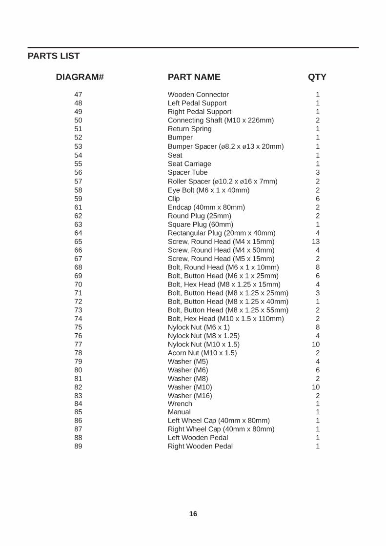
PARTS LIST
DIAGRAM# PART NAME QTY
16
47 Wooden Connector 148 Left Pedal Support 149 Right Pedal Support 150 Connecting Shaft (M10 x 226mm) 251 Return Spring 152 Bumper 153 Bumper Spacer (ø8.2 x ø13 x 20mm) 154 Seat 155 Seat Carriage 156 Spacer Tube 357 Roller Spacer (ø10.2 x ø16 x 7mm) 258 Eye Bolt (M6 x 1 x 40mm) 259 Clip 661 Endcap (40mm x 80mm) 262 Round Plug (25mm) 263 Square Plug (60mm) 164 Rectangular Plug (20mm x 40mm) 465 Screw, Round Head (M4 x 15mm) 1366 Screw, Round Head (M4 x 50mm) 467 Screw, Round Head (M5 x 15mm) 268 Bolt, Round Head (M6 x 1 x 10mm) 869 Bolt, Button Head (M6 x 1 x 25mm) 670 Bolt, Hex Head (M8 x 1.25 x 15mm) 471 Bolt, Button Head (M8 x 1.25 x 25mm) 372 Bolt, Button Head (M8 x 1.25 x 40mm) 173 Bolt, Button Head (M8 x 1.25 x 55mm) 274 Bolt, Hex Head (M10 x 1.5 x 110mm) 275 Nylock Nut (M6 x 1) 876 Nylock Nut (M8 x 1.25) 477 Nylock Nut (M10 x 1.5) 1078 Acorn Nut (M10 x 1.5) 279 Washer (M5) 480 Washer (M6) 681 Washer (M8) 282 Washer (M10) 1083 Washer (M16) 284 Wrench 185 Manual 186 Left Wheel Cap (40mm x 80mm) 187 Right Wheel Cap (40mm x 80mm) 188 Left Wooden Pedal 189 Right Wooden Pedal 1

17
NOTES
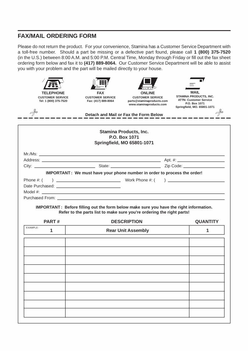
IMPORTANT : Before filling out the form below make sure you have the right information.Refer to the parts list to make sure you're ordering the right parts!
Detach and Mail or Fax the Form Below
Stamina Products, Inc.P.O. Box 1071
Springfield, MO 65801-1071
IMPORTANT : We must have your phone number in order to process the order!
FAX/MAIL ORDERING FORM
Please do not return the product. For your convenience, Stamina has a Customer Service Department witha toll-free number. Should a part be missing or a defective part found, please call 1 (800) 375-7520(in the U.S.) between 8:00 A.M. and 5:00 P.M. Central Time, Monday through Friday or fill out the fax sheetordering form below and fax it to (417) 889-8064. Our Customer Service Department will be able to assistyou with your problem and the part will be mailed directly to your house.
TELEPHONECUSTOMER SERVICETel: 1 (800) 375-7520
FAXCUSTOMER SERVICE
Fax: (417) 889-8064
MAILSTAMINA PRODUCTS, INC.
ATTN: Customer ServiceP.O. Box 1071
Springfield, MO. 65801-1071
ONLINECUSTOMER SERVICE
Mr./Ms:Address: Apt. #:City: State: Zip Code:
Phone #: ( ) Work Phone #: ( )Date Purchased:Model #:Purchased From:
PART # DESCRIPTION QUANTITY
1 Rear Unit Assembly 1EXAMPLE: