owner‘s manual - sinclair solutions
TRANSCRIPT

FULL DC INVERTER SYSTEMS
OWNER‘S MANUAL
KJR-120A
C O M M E R C I A L A I R C O N D I T I O N E R S S D V 4

Original instructions

● This manual gives detailed description of the precautions that should be brought to your attention during operation. ● In order to ensure correct service of the wired controller please read this manual carefully before using the unit. ● For convenience of future reference, keep this manual after reading it.

CONTENTS 1. Safety precautions........................................................................................1 2. Overview of wire controller............................................................................2 3. Outline of functions.......................................................................................2 4. Name and function description of LCD screen of wire controller..................3 5. Installation procedure...................................................................................4 6. Names of keys on wire controller and the keypad operation description.....6 7. Operation procedure of wire controller .......................................................10 Operation procedure of mode setting..........................................................10 Operation procudeure of water temperature setting ..................................10 Operation procedure of system on/off.........................................................10 Operation procedure of system information querying.................................10 Operation of remote on/ off.........................................................................10 Operation procudeure of HYSTERESIS TEMP.SET( δδ ) ............................10 Fault alarm processing................................................................................11 8. Using method..............................................................................................12 Appendix 1......................................................................................................15 Appendix 2......................................................................................................16

1. SAFETY PRECAUTIONS
The following contents are stated on the product and the operation manual, including usage, precautions against personal harm and property loss, and the methods of using the product correctly and safely. After fully understanding the following contents (identifiers and icons), read the text body and observe the following rules.
Identifier description
Identifier Meaning Means improper handling may lead to personal death or
severe injury. Means improper handling may lead to personal injury or
property loss. [Note]: 1. “Harm” means injury, burn and electric shock which need long-term treatment but need no hospitalization 2. “Property loss” means loss of properties and materials.
WWarning arning
Caution Caution
Icon description Meaning lcon
It indicates forbidding. The forbidden subject-matter is indicated in the icon or by images or characters aside.
It indicates compulsory implementation. The compulsory subject-matter is indicated in the icon or by images or characters aside.
1

Warning
WWarning arning
Please entrust the distributor or professionals to install the unit. The installers must have the relevant know-how. Improper installation performed by the user without perm ission may cause fire, electric,shock, personal injury or water leakage.
Delegate installation
Forbid
Forbid Usage Usage
Warningarning
Do not spray flammable aerosol to the wire controller directly. Otherwise, fire may occur.
Do not operate with wet hands or let water enter the wire controller. Otherwise, electric shock may occur.
2. OVERVIEW OF WIRE CONTROLLER
3. OUTLINE OF FUNCTIONS This wire controller provides the following functions:
Basic conditions of operating the wire controller
1. Applicable range of supply voltage: Input voltage is AC 220V±10%, powered to wire controller by attached power adapter. 2. Operating environment temperature of wire controller: -15℃~+43℃.
3. Operating RH of wire controller: RH40%~RH90%.
1. Connect with the outdoor unit through the terminals P, Q and E. Connect with the upper unit through the terminals X, Y
2

4. NAME AND FUNCTION DESCRIPTION OF LCD SCREEN OF WIRE CONTROLLER
3
and E(reserved).Connect with other wire controllers through the terminals P, Q and E. 2. Set the action mode through the keypad operation. 3. Provide the LCD display function. 4. Provide the timing startup function. 5. Real-time clock function (the wire controller inner place 3V battery ) When the wire controller is powered on, the LCD will display the current time; if it is powered off, the clock will not be displayed, then it will be autoupdated when the wire controller is re-power on.
Display time data
Display operation mode
Display query data
Display operation status

4
5. INSTALLATION PROCEDURE Installation procedure:
NOTE
Outdoor unit #00
Outdoor unit #01
Outdoor unit #02
Outdoor unit #15
Wire Controller #00
Use PQE connect with the outdoor units.
Please connect the attached shorted-wires to the corresponding communi-cation port COM(I) or COM(O) in the main control board of the last parallel unit (dial code ). Directly connect to the last parallel unit if only one unit is connected.

5
The wiring procedure and principles are shown in the figure:
P
Blac
k
Q
Gra
y
E
Yello
w
Y X
Outdoor electric control box
Communicate with upper unit(reserved).
Please use 3-cord shield wire for connection. The wire length depends on the specific situation in the installation.
wire controller
5-bit terminal base
If it is under the host computer network control, displays, otherwise there is no display.
6
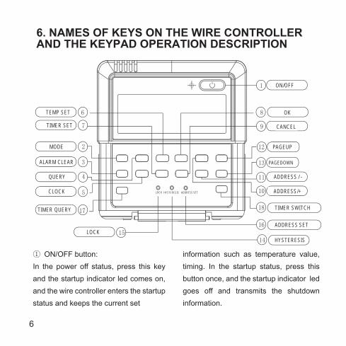
6. NAMES OF KEYS ON THE WIRE CONTROLLER AND THE KEYPAD OPERATION DESCRIPTION
① ON/OFF button: In the power off status, press this key and the startup indicator led comes on, and the wire controller enters the startup status and keeps the current set
information such as temperature value, timing. In the startup status, press this button once, and the startup indicator led goes off and transmits the shutdown information.
1
12
13
10
11
16
2
3
4
15
7
5
9
R
6 8
14
ON/OFF
OK
CANCEL
PAGEUP
PAGEDOWN
ADDRESS / -
ADDRESS/+
HYSTERESIS
ADDRESS SET
18 TIMER SWITCH
TEMP SET
TIMER SET
MODE
ALARM CLEAR
QUERY
CLOCK
17 TIMER QUERY
LOCK
HYSTERESIS LOCK ADDRESS SET
7
③ ALARM CLEAR button Press the button, then can clear some errors which need to operate manually for recovery. These errors represent there are problems while the unit is operating, but will not affect the system safety. If this type of error came out frequently then it needs to check and maintain the unit. ④ QUERY button Press the button, inquire state informa-tion of No. 0 to No. 15 outdoor units (the default is state information of No.0 unit) and enter inquiry state. After entering inquiry state, inquire the information of the former unit or the
② Operation mode button: In the power off status, press this button to select the operation mode. This function is invalid at power on status. Modes shifted sequence as follows: 1) Mode of KJR-120A air cooled modular wire controller: 2)Cooling only air cooled modular wire controller: → (Cooling)→ (Pump)
following unit through “ADDRESS/+” and “ADDRESS/-”. After a certain outdoor unit is selected, state information of the outdoor unit can be inquired through “page up” and “page down”. There are two possible inquiry sequences.1).Error→protection →outlet water temperature Tou→inlet water tempera-ture Tin→outdoor ambient temperatures T4→outdoor pipe temperature T3A→outdoor pipe temperature T3b→current of the compressor IA → current of the compressor Ib→anti-frozen temperature T6→electronic expansion valv opening FA→electronic expansion valv opening Fb→Error......The wired controller only displays the last fault information and the protection information, when query is conducted on fault and protection information.2). outdoor pipe temperature T3A→protection→Error→outlet water temperature Tou→current of the compressor Ib→current of the compres-sor IA →Setting temperature Ts→outdoor ambient temperatures T4→outdoor pipe temperature T3b→outdoor pipe temperature T3A......The wired controller only displays the last fault information and the protection informa-tion, when query is conducted on fault
→ (Cooling)→ (Heating)→ (Pump)

8
and protection information. ⑤ CLOCK button Press the “CLOCK” button once 【Press for the first time】, and enter to the week adjustment, 【Press for the second time】, and enter to the hour adjustment,【Press for the third time】,and enter the minute adjustment.The numerical valve ofweek, hour and minute can be adjusted by “ADDRESS/+” and “ADDRESS/-”, after the adjustment then press the OK button for the setting confirmation. ⑥ TEMP SET button Setup the total water outlet temperature in cooling and heating mode. The numerical valve of temp. setting can be adjusted by “ADDRESS/+” and “ADDRESS/-” ⑦TIMER SET button Press the button can enter the timer set adjustment.The numerical valve of the week,the start period,the end period,the operation mode and the setting temperation can be adjusted by “ADDRESS/+” and “ADDRESS/-”. ⑧ OK button Once finished upon, press OK key, wire controller will delivery order to main unit.
⑨ CANCEL buttonPress the button can return to the inerface previous and not save the setting information when the timer switch is ON.If press the button for 3 seconds,all the setting information of the timer will be cleared.ADDRESS/+ buttonPress this button at Check mode; whenselect the next modular, the operation status of the next modular will display; if the current modular is 15#, and the next one is 0#.Press this button for add address at wire address setting mode. If the wire controller address is 15, press this key will display the next address is 0.Press this button for add temperature at wire temperature setting mode. Press this button for add clock or time at wire clock or time setting mode. 11 ADDRESS/- buttonPress this button at query mode; when select the previous modular, the operation status of the previous modular will display; if the current modular is 0#, and the previous one is 15#.Press this button for minus address at wire address setting mode. If the wire controller address is 0, press this key will

9
display the next address is 15.Press this button for minus temperature at wire temperature setting mode. Press this button for minus clock or time at wire clock or time setting mode. 12 13 PAGEUP/DOWN button to spot check the operation parameters of unit in the main menu. 14 HYSTERESIS button (Hidden)Use a small round bar with 1mm diameter to press this button, then can adjust the return parameter δ=(2,3,4,5℃). The numerical valve of hystersis can be adjusted by “ADDRESS/+” and “ADDRESS/-”, after the adjustment then press the OK button for the setting confirmation. The factory defaults δ=2℃.
15 LOCK button (Hidden)Use a 1mm-diameter round bar to lock the current setting. Press this button again to unlock.16 ADDRESS SET button (Hidden)The address of wire controller can be set by pressing this button. The address range 0~15, therefore, 16 wire controller could be parallel at most.
When there is only one wire controller, it is necessary to execute this setting, the address of wire controller should be set to '0'(main wire controller) .17 TIMER QUERY buttonPress the button can inquire the timer setting information,such as the week,the setting operation mode,the start period,the end period and the setting temperature and so on.18 TIMER SWITCH buttonPress the button can open the weekly timer function or close the weekly timer function.

10
7. OPERATION PROCEDURE OF WIRE CONTROLLER● Operation procudeure of mode setting1. Press MODE at shutdown status, you could select appropriate mode as you want. The function is invalid at startup status.2.The modes which you can select depend on outdoor unit .
● Operation procudeure of water temperature setting1.Press [TEMP SET] button of wire controller when background light is on.2. Press [ADDRESS/+] or [ADDRESS/- ] button,you can select the water tempera-ture. Temperature range is not same in different operation mode . 3.Temperature range depend on outdoor unit .
●Operation procudeure of system ON/OFFPress [ON/OFF] button, running indicator
of wire controller is light, unit is start to run, and display running status at wire controller. Press this button once again, unit will stop running.
●Operation procudeure of system information querying1.Press [QUERY] ,enter Check status.2.Press [ADDRESS/+] or [ADDRESS/-] button, select the unit you want to query.3.Press [PAGEUP] or [PAGEDOWN] button to query the unit information, which includes E-, P-, Tou, Tin, T4,T3A, T3b ,IA, Ib, T6, FA, Fb or T3A, P-, E-,Tout, Ib, IA, Ts, T4, T3B.
●Operation of remote on/off If the main unit’s is under the remote on/off control, Net-ONNet-ON flashes, and communicate with upper unit is invalid.
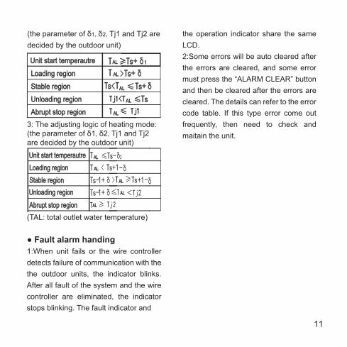
●Operation procudeure of HYSTERESIS TEMP.SET(δ ) 1:Through the hysteresis setting, the system can adjust the load effectively.2:The adjusting logic of cooling mode :
11
(the parameter of δ1,δ2,Tj1 and Tj2 are decided by the outdoor unit)
3: The adjusting logic of heating mode: (the parameter of δ1,δ2,Tj1 and Tj2 are decided by the outdoor unit)
(TAL: total outlet water temperature)
● Fault alarm handing1:When unit fails or the wire controller detects failure of communication with the the outdoor units, the indicator blinks. After all fault of the system and the wire controller are eliminated, the indicator stops blinking. The fault indicator and
Unit start temperautre Unit start temperautre
Loading region Loading region T T > > Ts+ + δ
Stable region Stable region Ts s < < T T ≤Ts+ + δ
Unloading region Unloading region Tj j 1 1 <T T ≤Ts s
Abrupt stop region Abrupt stop region
T T AL AL ≥Ts+ + δ1 1
T T ≤ Tj j 1 1 AL AL
AL AL
AL AL
AL AL
Unit start temperautre Unit start temperautre Loading region Loading region
Stable region Stable region Unloading region Unloading region
Abrupt stop region Abrupt stop region
T ≤Ts - δ2
T < Ts +1 - δ
Ts - 1+ δ > T ≥Ts +1 - δ Ts - 1+ δ ≤T <Tj 2
T ≥ Tj 2
AL AL
AL AL
AL AL
AL AL
AL AL
the operation indicator share the same LCD. 2:Some errors will be auto cleared after the errors are cleared, and some error must press the “ALARM CLEAR” button and then be cleared after the errors are cleared. The details can refer to the error code table. If this type error come out frequently, then need to check and maitain the unit.

12
CLOCK SET
WEEKLY TIMER SET 8. USING METHOD
set week
set hour ADDRESS/-
CLOCK
ADDRESS/+
CLOCK
CLOCK
ADDRESS/+
or
or
set minute
set done
ADDRESS/-
OK
ADDRESS/+ or
ADDRESS/-
Select week
Set Period 1 start hourADDRESS/-
ADDRESS/+
OK
OK
ADDRESS/+
or
or
Set Period 1 start minuteADDRESS/-
OK
ADDRESS/+ or
OK
OK
OK
OK
TIMER SET
Set Period 1 end hourADDRESS/- ADDRESS/+ or
Set Period 1 end minuteADDRESS/- ADDRESS/+ or
Set Period 1 modeADDRESS/- ADDRESS/+ or
Set Period 1 temperatureADDRESS/- ADDRESS/+
Set Timer Period 2
or
ADDRESS/-

13
WEEKLY TIMER QUERY
In operating, Press the key "CANCEL", to turn back to the previous step or the normal display interface.
NOTE
In operating, Press the key "CANCEL", to turn back to the previous step or the normal display interface.
NOTE
Select query week
Select query Period 1or Period 2
ADDRESS/-
ADDRESS/+
OK
OK
ADDRESS/+
or
or
Select query start time or end timeADDRESS/-
OK
ADDRESS/+ or
To normal display
ADDRESS/-
TIMER QUERY
Set Period 2 start hourADDRESS/-
OK
ADDRESS/+ or
Set Period 2 start minuteADDRESS/-
OK
ADDRESS/+ or
OK
OK
OK
OK
Set Period 2 end hourADDRESS/- ADDRESS/+ or
Set Period 2 end minuteADDRESS/- ADDRESS/+ or
Set Period 2 modeADDRESS/- ADDRESS/+ or
Set Period 2 temperatureADDRESS/- ADDRESS/+ or
Select weekADDRESS/- ADDRESS/+ or
Set Timer Period 2
OK

14
1.Before power failure of the heating water system or wire controller, the wire controller memorizes the status of the unit automatically, and sets the water temperature value except timing on/off function. After being powered on, the wire controller will send the relevant signals to the heating water system according to memorized status before power failure, in order to ensure that the unit can run in the originally set status after restoration of the power supply. 2. In the normal status,the background light is off.Press any key can only turn on the background light .3. In order to protect the equipments, it is not allowed to change the running mode quickly or frequently. It should operate the wire controller to start up the unit after 3 minutes later or all units are shutdown. 4. The wire controller and the outdoor unit must connect with the same power supply, powered up and powered off
simultaneously. It is not allowed to cut off the power supply separately.5. When several wire-controllers are parallel connected, the timing message can not communicating in these wire-controllers, and the timing will work separately. In order not to confuse, we suggest set the timing message on one wire-controller for the reason of indoor unit performance is compliance with the sequence of setting time.6.During changing or installing the battery, pay attention to the “+”,“-” poles of the battery and install it correctly, or will damage the control panel or battery, even worse will put lives at risk.
NOTE

15
Appendix 1:
E0 E1 E2 E3 E4 E5 E6 E7 E8 E9 Eb EC EE EF P0 P1 P2 P3 P4 P5 P6 P7 P9
Pb PC Pd
PF
Error of outdoor EEPROM Power supply wire phase error Communication error Error of total outlet water temp. Sensor(Be valid for main unit) Unit outlet water temprature sensor failure System A condenser temp. Sensor failure System B condenser temp. Sensor failure
Error of outdoor ambient temp. Sensor
Error of waterflow detection (manual recovery) Evaporator anti freeze protection sensor failure Wire control detect that the units on-line have decreased. EEPROM error of the wire controller Unit inlet water temprature sensor failure System A high pressure/discharge protection (manual recovery) System A low pressure protection (manual recovery) System B high pressure/discharge protection (manual recovery) System B low pressure protection (manual recovery) System A current protection (manual recovery) System B current protection (manual recovery)
System A condensor high ambient protection System B condensor high ambient protection Temperature protection of the differences between water inlet and water outlet
System anti-frozen protection
Communication between the main control panel with electronic lock failure
PA Start refrigeration low environment temperature protection
Anti-freezing pressure protection of the system A (manual recovery) Anti-freezing pressure protection of the system B (manual recovery)
Power supply phase sequence module protection
PE Refrigeration evaporator low ambient protection (manual recovery)
EP Wire controller clock failure

Power supply wire phase error
Error of total outlet water temp. Sensor(Be valid for main unit) Unit outlet water temprature sensor failure System A condenser temp. Sensor failure System B condenser temp. Sensor failure
System A high pressure/discharge protection
System B high pressure/discharge protection
System A condensor high ambient protection System B condensor high ambient protection
Refrigeration evaporator low ambient protection
Refrigeration evaporator low ambient protection(The third time in one hour)
16
Appendix 2:
E0 E1 E2 E3 E4 E5 E6 E7 E8 E9 EA Eb EC Ed EE EF P0 P1 P2 P3 P4 P5 P6 P7 P8 Pb PE
Error of waterflow detection (The third time)
Communication error
Error of outdoor ambient temp. Sensor Error of system A digital compressor air exhaust temperature protection Error of waterflow detection (The first and second time) From main unit detection to auxiliary unit quantity decrease Error of CEB A anti-frozen temperature sensor Wire control detect that the units on-line have decreased.
EEPROM error of the wire controller Error of CEB B anti-frozen temperature sensor
System A low pressure protection
System B low pressure protection System A current protection System B current protection
System A digital compressor air exhaust temperature protection System anti-frozen protection
PA Start refrigeration low environment temperature protection
PF Communication between the main control panel with electronic lock failure EP Wire controller clock failure