owner's manual - sears parts direct · 2007-08-14 · sae 30w (above 32°f/0°c) sae 5w-30...
TRANSCRIPT
I
OWNER'S MANUALMODELNO. FN620J3.5 HP17 InchTiller
Assembly• Operation
Customer Responsibilities• Service and Adjustments
• Storage• Troubleshooting
• Repair Parts
For Parts and Service, contact our authorized distributor: call 1-800-849-1297For Technica| Assistance: call 1-800-829-5886
181117 1.7.02 TRPRINTED IN U.S.A.
SAFETY RULESSAFE OPERATION PRACTICES FOR WALK-BEHIND POWERED ROTARYTILLERS
TRAINING
• Read the Owner's Manual caretully. Be thoroughlyfamiliar with the controls and the proper use of theequipment. Know how to stop the unit and disengage thecontrols quickly.Never allow children to operate the equipment. Neverallow adults to operate the equipment without properinstruction.
Keep the area of operation clear of all persons, particu-larly small children, and pets.
PREPARATION
Thoroughly inspect the area where the equipment is tobe used and remove all foreign objects.
• Disengage all clutches and shift into neutral beforestarting the engine (motor).
• Do not operatethe equipment without wearing adequateoutergarments. Wear footwear that will improve footingon slippery surfaces.Handle fuel with care; it is highly flammable.
• Use an approved fuel container.• Never add fuel to a running engine or hot engine.
Fill fuel tank outdoors with extreme care. Never fill fueltank indoors.
• Replace gasoline cap securely and clean up spilled fuelbefore restarting.Use extension cords and receptacles as specified bythe manufacturer for all units with electric drive motorsor electric starting motors.
• Never attempt to make any adjustments while theengine (motor) is running (except where specificallyrecommended by manufacturer).
OPERATION
• Do not put hands or feet near or under rotating parts.Exercise extreme caution when operating on or crossinggravel drives, walks, or roads. Stay alert for hiddenhazards or traffic. Do not carry passengers.
• After striking a foreign object, stop the engine (motor),remove the wire from the spark plug, thoroughly inspectthe tiller for any damage, and repair the damage beforerestarting and operating the tiller.
• Exercise caution to avoid slipping or falling.• If the unit should start to vibrate abnormally, stop the
engine (motor) and check immediately for the cause.Vibration is generally a warning of trouble.Stop the engine (motor) when leaving the operatingposition.
• Take all possible precautions when leaving the machineunattended. Disengage the tines, shift into neutral, andstop the engine.
• Before cleaning, repairing, or inspecting, shut off theengine and make certain all moving parts have stopped.Disconnect the spark plug wire, and keep the wire awayfrom the plug to prevent accidental starting. Disconnectthe cord on electric motors.
Do not run the engine indoors; exhaust fumes aredangerous.
Neveroperate the tillerwithoutproperguards, plates, orother safety protective devices in place.Keep children and pets away.Do not overload the machine capacity by attempting totill too deep at too fast a rate.Never operate the machine at high speeds on slipperysurfaces. Look behind and use care when backing.Never allow bystanders near the unit.Use only attachments and accessories approved by themanufacturer of the tiller.
Never operate the tiller without good visibility or light.Be careful when tilling in hard ground. The tines maycatch in the ground and propel the tiller forward. If thisoccurs, let go of the handlebars and do not restrain themachine.
MAINTENANCE AND STORAGE
• Keep machine, attachments, and accessories in safeworking condition.
• Check shear pins, engine mounting bolts, and otherbolts at frequent intervals for proper tightness to be surethe equipment is in safe working condition.Never store the machine with fuel in the fuel tank insidea building where ignition sources are present, such ashot water and space heaters, clothes dryers, and thelike. Allow the engine to cool before storing in anyenclosure.
• Always refer to the operator's guide instructions forimportant details if the tiller is to be stored for anextended period.
- IMPORTANT -
CAUTIONS, IMPORTANTS, AND NOTES ARE A MEANSOF ATTRACTING ATTENTION TO IMPORTANT ORCRITICAL INFORMATION IN THIS MANUAL.
IMPORTANT: USED TO ALERT YOU THAT THEREISAPOSSIBILITY OF DAMAGING THIS EQUIPMENT.NOTE: Gives essential information that will aid you tobetter understand, incorporate, or execute a particular setof instructions.
Look for this symbolto point out impor- I
tant safety precautions. It meansCAUTION!!! BECOME ALERT!!! YOURSAFETY IS INVOLVED.
CAUTION: Always disconnect sparkplug wire and place wire where it can notcontact spark plug in order to preventaccidental starting when setting up,transporting, adjusting or making re-pairs.
WARNINGThe engine exhaust from this product con-tains chemicals known to the State of Califor-nia to cause cancer, birth defects, or otherreproductive harm.
2
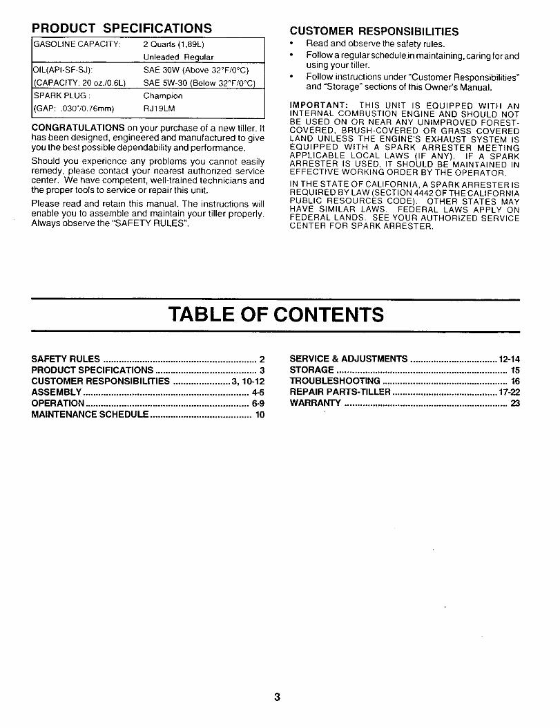
PRODUCT SPECIFICATIONSGASOLINE CAPACITY:
3IL(API-SF-SJ):
CAPACITY: 20 oz./0.6L)
SPARK PLUG :
GAP: .030"/0.76mm)
2 Quarts (1,89L)
Unleaded Regular
SAE 30W (Above 32°F/0°C)
SAE 5W-30 (Below 32_F/0°C)
Champion
RJ19LM
CONGRATULATIONS on your purchase of a new tiller. Ithas been designed, engineered and manufactured to giveyou the best possible dependability and performance.
Should you experience any problems you cannot easilyremedy, please contact your nearest authorized servicecenter. We have competent, well-trained technicians andthe proper tools to service or repair this unit.Please read and retain this manual. The instructions willenable you to assemble and maintain your tiller properly.Always observe the "SAFETY RULES".
CUSTOMER RESPONSIBILITIES
Read and observe the safety rules.Follow a regular schedule in maintaining, caring for andusing your tiller.Follow instructions under "Customer Responsibilities"and "Storage" sections of this Owner's Manual.
IMPORTANT: THIS UNIT IS EQUIPPED WITH ANINTERNAL COMBUSTION ENGINE AND SHOULD NOTBE USED ON OR NEAR ANY UNIMPROVED FOREST-COVERED, BRUSH-COVERED OR GRASS COVEREDLAND UNLESS THE ENGINE'S EXHAUST SYSTEM ISEQUIPPED WITH A SPARK ARRESTER MEETINGAPPLICABLE LOCAL LAWS (IF ANY). IF A SPARKARRESTER IS USED, IT SHOULD BE MAINTAINED INEFFECTIVE WORKING ORDER BY THE OPERATOR.
IN THE STATE OF CALIFORNIA, A SPARKARRESTER ISREQUIRED BY LAW (SECTION 4442 OF THE CALIFORNIAPUBLIC RESOURCES CODE). OTHER STATES MAYHAVE SIMILAR LAWS. FEDERAL LAWS APPLY ONFEDERAL LANDS. SEE YOUR AUTHORIZED SERVICECENTER FOR SPARK ARRESTER.
TABLE OF CONTENTS
SAFETY RULES ........................................................... 2PRODUCT SPECIFICATIONS ....................................... 3CUSTOMER RESPONSIBILITIES ...................... 3, 10-12ASSEMBLY ................................................................ 4-5OPERATION ............................................................... 6-9MAINTENANCE SCHEDULE ....................................... 10
SERVICE & ADJUSTMENTS .................................. 12-14STORAGE ................................................................... 15TROUBLESHOOTING ................................................. 16REPAIR PARTS-TILLER ......................................... 17-22WARRANTY ................................................................ 23
3
ASSEMBLY
Your new tiller has been assembled at the factory with exception of those parts left unassembled for shipping purposes. Toensure safe and prope roperation of your tiller all parts and hardware you assemble must be tightened securely. Use the correcttools as necessary to insure proper tightness.
TOOLS REQUIRED FOR ASSEMBLY
A socket wrench set will make assembly easier. Standardwrench sizes are listed.
(1) Utility knife
(1) Pair of pliers
(1) Screwdriver
(2) 1/2" wrenches
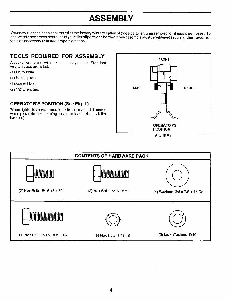
OPERATOR'S POSITION (See Fig. 1)
When right or lefthand is mentioned in this manual, itmeanswhen youare inthe operatingposition (standing behind tillerhandles).
FRONT
LEFT RIGHT
OPERATOR'SPOSITION
FIGURE 1
(2) Hex Bolts 5/16-18 x 3/4
CONTENTS OF HARDWARE PACK
U!ll!l!!l!l!tl!l!l!131!l!131!l!l!l!!
(2) Hex Bolts 5116-16 x 1 (4) Washers 3/8 x 7/8 x 14 Ga.
©(1) Hex Bolts 5/16-18 x 1-1/4 (5) Hex Nuts 5/16-18 (5) Lock Washers 5/16
4
ASSEMBLY
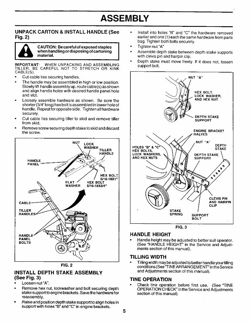
UNPACK CARTON & INSTALL HANDLE (SeeFig. 2)
I_ AUTION: Becarefulofexposedstaples Iwhen handling or disposing of cartoningmaterial.
IMPORTANT: WHEN UNPACKING AND ASSEMBLINGTILLER, OE CAREFUL NOT TO STRETCH OR KINKCABLE(S).
Cut cable ties securing handles.The handle may be assembled in high or low position.Slowly lift handle assembly up, route cable(s) as shownand align handle holes with desired handle panel holeand slot.
Loosely assemble hardware as shown. Be sure theshorter (3/4" long) hex bolt is assembled in lower hole ofhandle. Repeatforoppositeside. Tightenallhardwaresecurely.Cut cable ties securing tiller to skid and remove tillerfrom skid.
• Remove screw securing depth stake to skid and discardthe screw.
HANDLEPANEL
NUT LOCK
WASHERTILLERHANDLE
HANDLE_
PANELBOLTS
E_ FLAT
WASHER
CABL
TILLER J_'_HANDLES l_-
HEX BOL_16-18X1"
HEX BOLT5_6-18X_4"
FIG. 2
INSTALL DEPTH STAKE ASSEMBLY(See Fig. 3)• Loosen nut =A".
Remove hex nut, Iockwasher and bolt securing depthstake support to engine brackets. Save the hardware forreassembly.
• Raise and position depth stake support to align holes insupport with holes "B" and "C" in engine brackets.
Install into holes "B" and "C" the hardware removedearlier and one (1) each the same hardware from partsbag. Tighten both bolts securely.Tighten nut "A"
Assemble depth stake between depth stake supportswith clevis pin and hairpin clip.Depth stake must move freely. If it does not, loosensupport bolt.
NUT "A"
HEX BOLT,LOCK WASHER,AND HEX NUT
DEPTH STAKESUPPORT
\
HOLES"B"&"C"HEX BOLTS,LOCK WASHERS,AND HEX NUTS
ENGINE BRACKETHALVES
NUT "A"DEPTHSTAKE
STAKESPRING
CLEVIS PINAND HAIRPINCLIP
SUPPORTBOLT
FIG. 3
HANDLE HEIGHT
• Handle height may be adjusted to better suit operator.(See "HANDLE HEIGHT" in the Service and Adjust-ments section of this manual).
TILLING WIDTH
Tillingwidth may be adjusted to better handle your tillingconditions (See"TIN EARRAN GEMENT"in the Serviceand Adjustments section of this manual).
TINE OPERATION
• Check tine operation before first use. (See "TINEOPERATION CHECK" in the Service and Adjustmentssection of this manual).
5
OPERATION
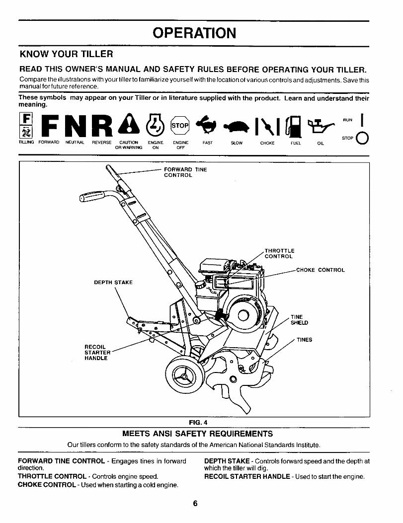
KNOW YOUR TILLER
READ THIS OWNER'S MANUAL AND SAFETY RULES BEFORE OPERATING YOUR TILLER.
Compare the illustrationswith you r tillerto familiarize yourself with the location of various controls and adjustments. Save thismanual for future reference.
These symbols may appear on your Tiller or in literature supplied with the product. Learn and understand theirmeaning.
TILLING FORWARD NEUTRAL OILOR WARNING ON OFF
FORWARD TINECONTROL
THROTTLE
DEPTH STAKE
CONTROL
TINESHIELD
RECOILSTARTERHANDLE
TINES
FIG. 4
MEETS ANSI SAFETY REQUIREMENTS
Our tillers conform to the safety standards of the American National Standards Institute.
FORWARD TINE CONTROL - Engages tines in forwarddirection.
THRO'n'LE CONTROL - Controls engine speed.CHOKE CONTROL - Used when starting a cold engine.
DEPTH STAKE - Controls forward speed and the depth atwhich the tiller will dig.RECOIL STARTER HANDLE - Used to start the engine.
6
OPERATION
The operation of any tiller can result in foreign objects thrown into the eyes, which can resultin severe eye damage. Always wear safety glasses or eye shields before starting your tillerand while tilling. We recommend a wide vision safety mask over spectacles or standardsafety glasses.
DEPTH STAKE (See Fig. 6)HOW TO USE YOUR TILLER
Know how to operate all controls before adding fuel and oilor attempting to start engine.
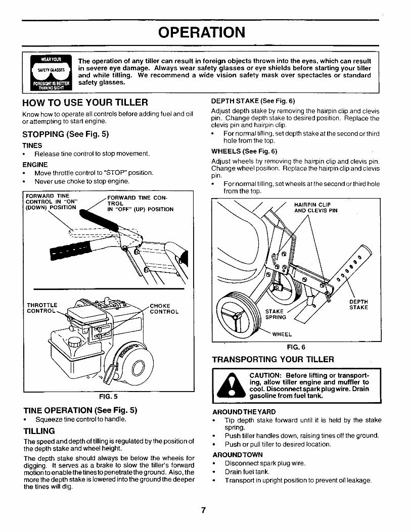
STOPPING (See Fig. 5)
TINESRelease tine control to stop movement.
ENGINEMove throttle control to "STOP" position.Never use choke to stop engine.
FORWARD TINECONTROL IN "ON"(DOWN) POSITION
%TINE CON-
TROLIN "OFF" (UP) POSITION
"HROTTLE CHOKE3L
FIG. 5
TINE OPERATION (See Fig. 5)• Squeeze tine control to handle.
TILLING
The speed and depth of tilling is regulated by the position ofthe depth stake and wheel height.
The depth stake should always be below the wheels fordigging. It serves as a brake to slow the tiller's forwardmotion to enablethe tinesto penetrate the ground. Also, themore the depth stake is lowered into the ground the deeperthe tines will dig.
Adjust depth stake by removing the hairpin clip and clevispin. Change depth stake to desired position. Replace theclevis pin and hairpin clip.
For normal tilling, set depth stake at the second or thirdhole from the top.
WHEELS (See Fig. 6)
Adjust wheels by removing the hairpin clip and clevis pin.Change wheel position. Replace the hairpin clip and clevispin.• For normal tilling, set wheels at the second or third hole
from the top.
HAIRPIN CLIPAND CLEVIS PIN
DEPTHSTAKE
FIG. 6
TRANSPORTING YOUR TILLER
I ICAUTION: Before lifting or transport- |ing, allow tiller engine and muffler to [cool. Disconnectsparkplugwire. Draingasoline from fuel tank.
AROUNDTHEYARDTip depth stake forward until it is held by the stakespring.Push tiller handles down, raising tines off the ground.
• Push or pull tiller to desired location.
AROUNDTOWN
• Disconnect spark plug wire.• Drain fuel tank.
• Transport in upright position to prevent oil leakage.
7
OPERATION
BEFORE STARTING ENGINEIMPORTANT: BE VERY CAREFUL NOT TO ALLOW DIRTTO ENTER THE ENGINE WHEN CHECKING OR ADDINGOIL OR FUEL. USE CLEAN OIL AND FUEL AND STOREIN APPROVED, CLEAN, COVERED CONTAINERS. USECLEAN FILL FUNNELS.
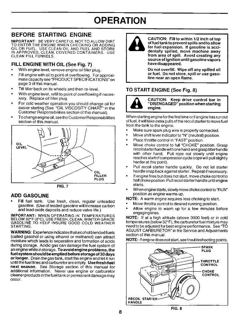
FILL ENGINE WITH OIL (See Fig. 7)• With engine level, remove engine oil filler plug.
Fill engine with oil to point of overflowing. For approxi-mate capacity see "PRODUCT SPECIFICATIONS" onpage 3 of this manual.Tilt tiller back on its wheels and then re-leveL
With engine level, refill to point of overflowing if neces-sary. Replace oil filler plug.For cold weather operation you should change oil foreasier starting (See "OIL VISCOSITY CHART' in theCustomer Responsibilities section of this manual).To change engine oil, see the Customer Responsibilitiessection of this manual.
OIL
OILFILLERPLUG
FIG. 7
ADD GASOLINE
• Fill fuel tank. Use fresh, clean, regular unleadedgasoline. (Use of leaded gasoline will increase carbonand lead oxide deposits and reduce valve life.)
IMPORTANT: WHEN OPERATING IN TEMPERATURESBELOW 32°F (0°C), USE FRESH, CLEAN, WINTER G RADEGASOLINE TO HELP INSURE GOOD COLD WEATHERSTARTING.
WARNING: Experience indicates that alcohol blended fuels(called gasohol or using ethanol or methanol) can attractmoisture which leads to separation and formation of acidsdudng storage. Acidic gas can damage the fuel system ofan engine while instorage. To avoid engine problems, thefuel system should be emptied before storage of 30 daysor longer. Drain the gas tank, start the engine and let it rununtilthe fuel linesandcarburetorareempty. Usefresh fuelnext season. See Storage section of this manual foradditional information. Never use engine or carburetorcleaner products inthe fueltank orpermanent damage mayOccur.
CAUTION: Fill to within 112 inch of topof fuel tank to prevent spills and to allowfor fuel expansion. If gasoline is acci-dentally spilled, move machine awayfrom area of spill. Avoid creating anysource of ignition until gasoline vaporshave disappeared.
Do not overfill. Wipe off any spilled oilor fuel. Do not store, spill or use gaso-line near an open flame.
TO START ENGINE (See Fig. 8)
|
_lb CAUTION: Keep drive control bar in I"DISENGAGED" position when starting Iengine.
When starting engine for the firsttime or if engine has run outof fuel, it will take extra pulls of the recoil starter to move fuelfrom the tank to the engine.
Make sure spark plug wire is properly connected.Move shift lever indicator to "N" (neutral) position.Place throttle control in "FAST" position.Move choke control to full "CHOKE" position. Grasprecoil starter handle with one hand and grasp tiller handlewith other hand. Pull rope out slowly until enginereaches start of compression cycle (rope will pull slightlyharder at this point).Pull recoil starter handle quickly. Do not let starterhandle snap back against starter. Repeat if necessary.
• If engine fires but does not start, move choke control tohalf choke position. Pull recoil starter handle until enginestarts.
• When engine starts, slowly move choke control to"RU N"position as engine warms up.
NOTE: A warm engine requires less choking to start.Move throttle control to desired running position.
• Allow engine to warm up for a few minutes beforeengagingtines.
NOTE: If at a high altitude (above 3000 feet) or in coldtemperatures (below 32°F), the carburetorfuel mixture mayneed to be adjusted for best engine performance. See 'q'OADJUST CARBURETOR" in the Service and Adjustmentssection of this manual.
NOTE: Ifengine does not start, see troubleshooting points.
SPARKPLUG
CONTROL
CONTROL
RECOIL STARTERHANDLE
FIG. 88
OPERATION
BREAKING IN YOUR TILLER
Break-in your belts, pulleys and tine control before youactually begin tilling.• Start engine, tip tines off ground by pressing handles
down and engage line control to start tine rotation. Allowtines to rotate for five minutes.
Check tine operation and adjust if necessary. See"TINE OPERATION CHECK" in the Service and Adjust-ments section of this manual.
TILLING HINTS
I_ CAUTION: Until you are accustomed to
handling your tiller, start actual field usewith throttle in slow position (mid-waybetween "FAST" and "IDLE").
To help tiller move forward, liftup the handles slightly (thuslifting depth stake out of ground). To slow down the tiller,press down on handles.
If you are straining or tiller is shaking, the wheels and depthstake are not set properly in the soil being tilled. The propersetting of the wheels and depth stake is through trial and errorand depends upon the soil condition. (The harder or wetterthe ground, the slower the engine and tine speed needed.Under these poorconditions, at fast speed the tiller will runand jump over the ground).
A properly adjusted tiller will dig with little effort from theoperator.
Tilling is digging into, turning over, and breaking uppacked soil before planting. Loose, unpacked soil helpsroot growth. Best tilling depth is 4" to 6" (10-15 cm). Atiller will also clear the soil of unwanted vegetation. Thedecomposition of this vegetable matter enriches thesoil. Depending on the climate (rainfall and wind), it maybe advisable to till the soil at the end of the growingseason to further condition the soil.
• Soil conditions are important for proper tilling. Tines willnot readily penetrate dry, hard soil which may contributeto excessive bounce and difficult handling of your tiller.Hard soil should be moistened before tilling; however,extremely wet soil will "ball-up" or clump during tilling.Wait until the soil is less wet in order to achieve the bestresults. When tilling in the fall, remove vines and longgrass to prevent them from wrapping around the tineshaft and slowing your tilling operation.
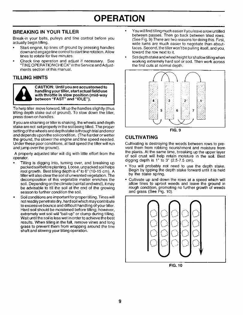
You will find tilling much easier if you leave a row untilledbetween passes. Then go back between tilled rows.(See Fig. 9) There are two reasons for doing this. First,wide turns are much easier to negotiate than about-faces. Second, the tiller won't be pulling itself, and you,toward the row next to it.
Set depth stake and wheel height for shallow tilling whenworking extremely hard soil or sod. Then work acrossthe first cuts at normal depth.
FIG. 9
CULTIVATING
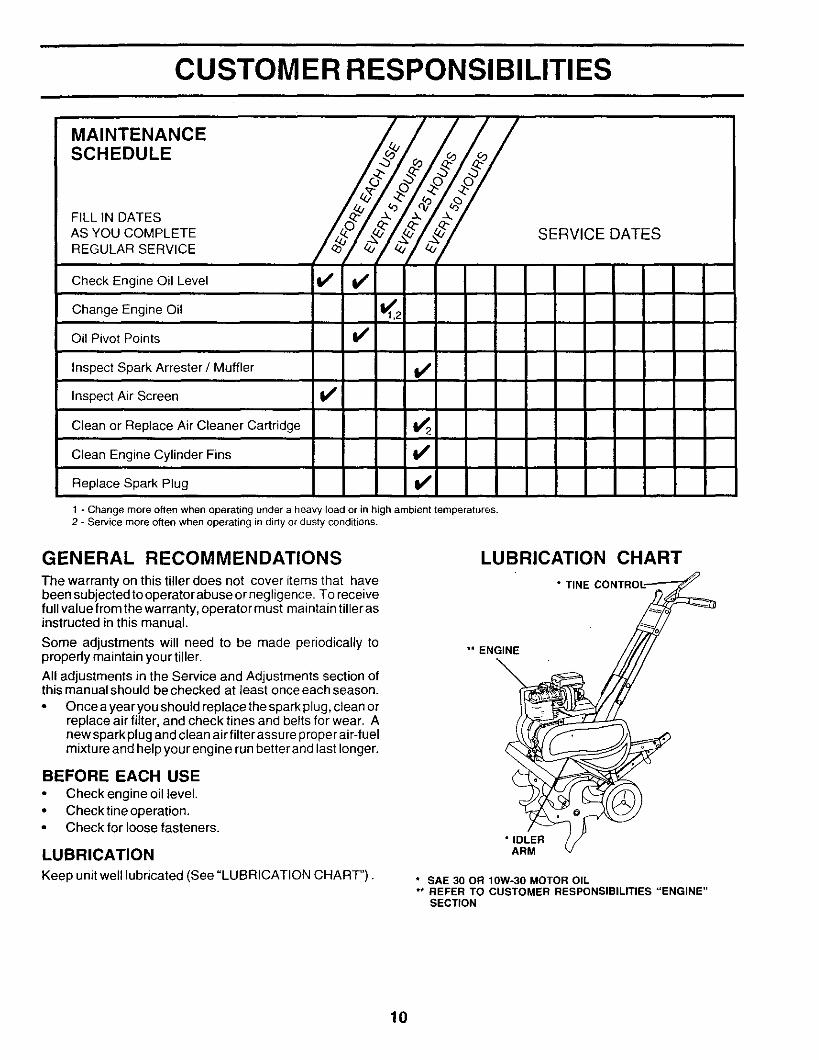
Cultivating is destroying the weeds between rows to pre-vent them from robbing nourishment and moisture fromthe plants. At the same time, breaking up the upper layerof soil crust will help retain moisture in the soil. Bestdigging depth is 1" to 3" (2.5-7.5 cm).
• You will probably not need to use the depth stake.Begin by tipping the depth stake forward until it is heldby the stake spring.
• Cultivate up and down the rows at a speed which willallow tines to uproot weeds and leave the ground inrough condition, promoting no further growth of weedsand grass (See Fig. 10).
A
FIG. 10
9
CUSTOMER RESPONSIBILITIES
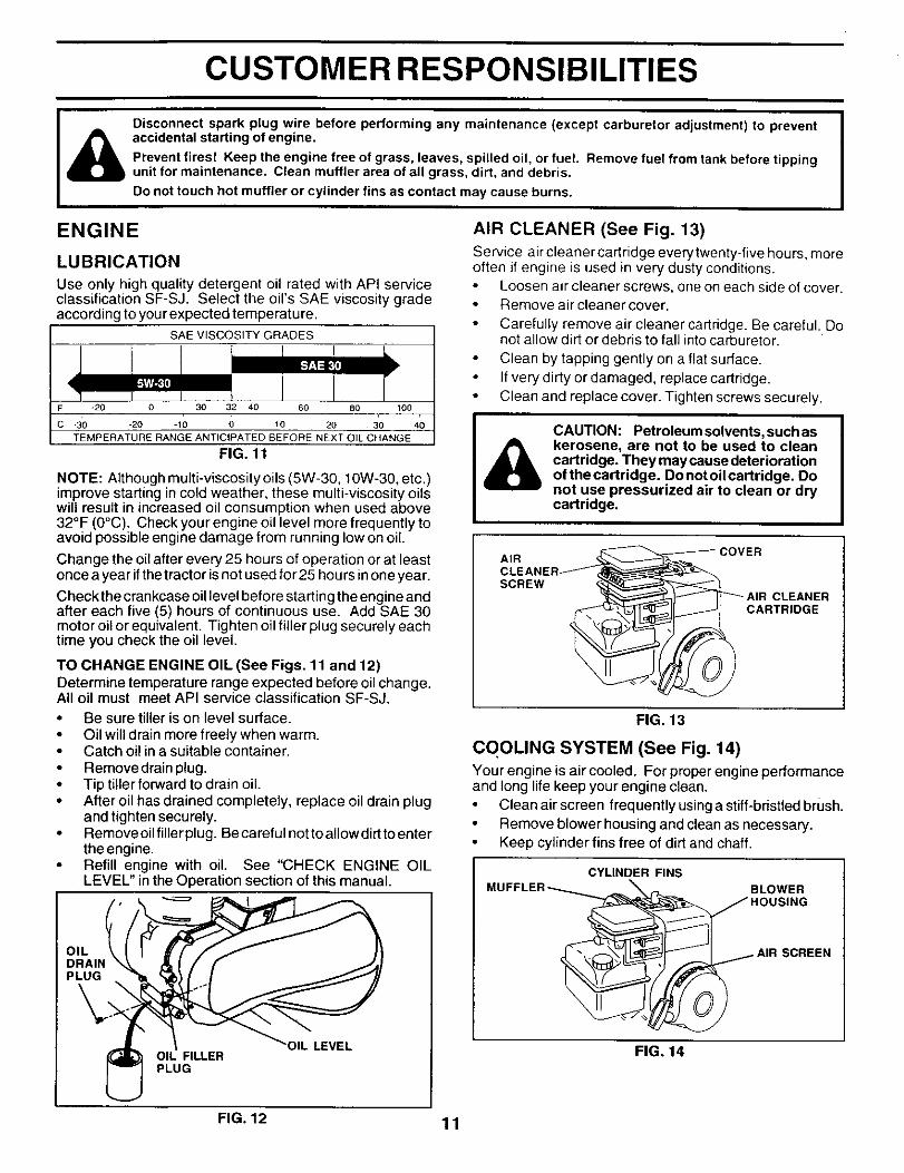
MAINTENANCESCHEDULE
FILL 1N DATESAS YOU COMPLETEREGULAR SERVICE
SERVICE DATES
Check Engine Oil Level If If
Change Engine Oil 1_1,2
Oil Pivot Points V'
Inspect Spark Arrester/Muffler If
Inspect Air Screen I_
Clean or Replace Air Cleaner Cartridge I/2
Clean Engine Cylinder Fins I,/
Replace Spark Plug If
1 - Changemoreoftenwhenoperatingundera heavy loador inhigh ambient temperatures.2 - Senlicemoreoftenwhenoperating in dirtyor dusty conditions.
GENERAL RECOMMENDATIONS
The warranty on this tiller does not cover items that havebeen subjected to operator abuse or negligence. To receivefull value from the warranty, operator must maintain tiller asinstructed in this manual.
Some adjustments will need to be made periodically topropedy maintain your tiller.
All adjustments in the Service and Adjustments section ofthis manual should be checked at least once each season.
• Once a yearyou should replace the spark plug, clean orreplace air filter, and check tines and belts for wear. Anew spark plug and clean air filter assure proper air-fuelmixture and help your engine run betterand last longer.
BEFORE EACH USECheck engine oil level.
• Check tine operation.• Check for loose fasteners.
LUBRICATION
Keep unit well lubricated (See "LUBRICATION CHART").
LUBRICATION CHART
° IDLERARM
* SAE 30 OR 10W-30 MOTOR OIL** REFER TO CUSTOMER RESPONSIBILITIES "ENGINE"
SECTION
10
CUSTOMER RESPONSIBILITIES
Disconnect spark plug wire before performing any maintenance (except carburetor adjustment) to preventaccidental starting of engine.
Prevent fires! Keep the engine free of grass, leaves, spilled oil, or fuel. Remove fuel from tank before tippingunit for maintenance. Clean muffler area of all grass, dirt, and debris.
Do not touch hot muffler or cylinder fins as contact may cause burns.
ENGINE
LUBRICATION
Use only high quality detergent oil rated with API serviceclassification SF-SJ. Select the oil's SAE viscosity gradeaccording to your expected temperature.
SAE VISCOSITY GRADESI
I IF -20 0 30 32 40 60 80 100
C -30 -20 -10 0 10 20 30 40
TEMPERATURE RANGE ANTICIPATED BEFORE NEXT OIL CHANGE
FIG. 11
NOTE: Although multi-viscosity oils (5W-30, 10W-30, etc.)improve starting in cold weather, these multi-viscosity oilswill result in increased oil consumption when used above32°F (0°C). Check your engine oil level more frequently toavoid possible engine damage from running low on oil
Change the oil after every 25 hours of operation or at leastonce a year if the tractor is not used for 25 hours in one year.
Check the crankcase oil level before starting the engine andafter each five (5) hours of continuous use. Add SAE 30motor oil or equivalent. Tighten oil filler plug securely eachtime you check the oil level.
TO CHANGE ENGINE OIL (See Figs. 11 and 12)Determine temperature range expected before oil change.All oil must meet API service classification SF-SJ.• Be sure tiller is on level surface.• Oil will drain more freely when warm.• Catch oil in a suitable container.• Remove drain plug.• Tip tiller forward to drain oil.• After oil has drained completely, replace oil drain plug
and tighten securely.• Remove oil filler plug. Be careful not to allow dirf to enter
the engine.Refill engine with oil. See "CHECK ENGINE OILLEVEL" in the Operation section of this manual.
OILDRAII_PLUG
LOIL FILLERPLUG
AIR CLEANER (See Fig. 13)
Service air cleaner cartridge everytwenty-five hours, moreoften if engine is used in very dusty conditions.
Loosen air cleaner screws, one on each side of cover.Remove air cleaner cover.
• Carefully remove air cleaner cartridge. Be careful. Donot allow dirt or debris to fall into carburetor.
Clean by tapping gently on a flat surface.If very dirty or damaged, replace cartridge.Clean and replace cover. Tighten screws securely.
CAUTION: Petroleum solvents, such askerosene, are not to be used to cleancartridge. They may cause deteriorationof thecartridge. Donot oilcartridge. Donot use pressurized air to clean or drycartridge.
AIR _ COVER
i '2RC ggR
FIG. 13
COOLING SYSTEM (See Fig. 14)Your engine is air cooled. For proper engine performanceand long life keep your engine clean.• Clean air screen frequently using a stiff-bristled brush.
Remove blower housing and clean as necessary.Keep cylinder fins free of dirt and chaff.
CYLINDER FINS
BLOWER
SCREEN
FIG, 14
FIG. 12 1
CUSTOMER RESPONSIBILITIES
MUFFLERDo not operate tiller without muffler. Do not tamper withexhaust system. Damaged mufflers or spark arresters couldcreate a fire hazard. Inspect periodically and replace ifnecessary. If your engine is equipped with a spark arresterscreen assembly, remove every 50 hours for cleaning andinspection. Replace if damaged.
SPARK PLUG
Replace spark plugs at the beginning of each tilling seasonor after every 50 hours of use, whichever comes first. Sparkplug type and gap setting is shown in "PRODUCT SPECIFI-CATIONS" on page 3 of this manual.
TRANSMISSION
Your transmission issealed and will only require lubricationif serviced.
CLEANINGClean engine, wheels, finish, etc. of all foreign matter.Keep finished surfaces and wheels free of all gasoline,oil, etc.
Protect painted surfaces with automotive type wax.
We do not recommend using a garden hose to clean your unitunless the muffler, air filter and carburetor are covered tokeep water out. Water in engine can result in a shortenedengine life.
SERVICE AND ADJUSTMENTS
I& AUTION: Disconnect spark plug wire from spark plug and place wire where it cannot come intocontact with plug. ITILLER
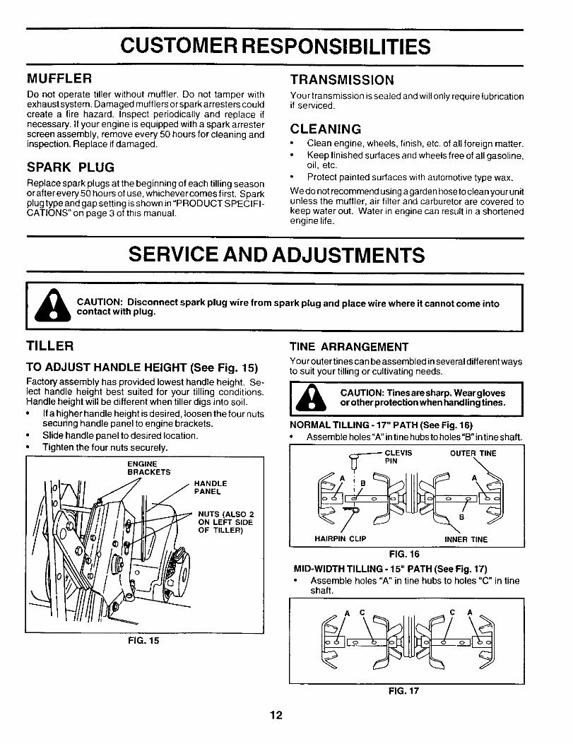
TO ADJUST HANDLE HEIGHT (See Fig. 15)
Factory assembly has provided lowest handle height. Se-lect handle height best suited for your tilling conditions.Handle height will be different when tiller digs into soil.• Ifa higher handle height is desired, loosen the four nuts
securing handle panel to engine brackets.• Slide handle panel to desired location.• Tighten the four nuts securely.
ENGINEBRACKETS
HANDLEPANEL
NUTS (ALSO 2ON LEFT SIDEOF TILLER)
FIG. 15
TINE ARRANGEMENT
Your outertines can be assembled inseveral differentwaysto suit your tilling or cultivating needs.
_ CAUTION: Tinesaresharp, Wear gloves Ior other protection when handling tines.
NORMAL TILLING - 17" PATH (See Fig. 16)Assemble holes"A" intine hubsto holes "B" intineshaft.
-----_-- CLEVIS OUTER TINE
PIN
A i B A
HAIRPIN CLIP INNER TINE
FIG. 16
MID-WIDTH TILLING - 15" PATH (See Fig. 17)• Assemble holes "A" in tine hubs to holes "C" in tine
shaft.
FIG, 17
12
SERVICE AND ADJUSTMENTS
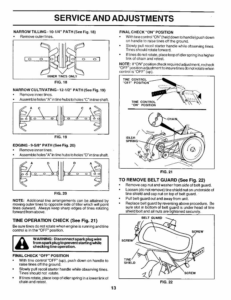
NARROW TILLING- 10-1/4" PATH (See Fig. 18)Remove outer tines.
I o
INNER TINES ONLY
ol
FIG. 18
NARROW CULTIVATING - 12-1/2" PATH (See Fig. 19)• Remove inner tines.
Assemble holes "A" in tine hubs to holes "C" in tine shaft.
O O O o
FIG. 19
EDGING - 9-5/8" PATH (See Fig. 20)• Remove inner tines.
• Assernbleholes"A"intinehubstoholes"D'intineshaft.
0 0 0 0
FIG. 20
NOTE: Additional tine arrangements can be attained bymoving outer tines to opposite side of tiller which will pointtines outward. Always keep sharp edges of tines rotatingforward from above.
TINE OPERATION CHECK (See Fig. 21)
Be sure tines do not rotate when engine is running and tinecontrol is in the "OFF" position.
I_ ARNING: Disconnectsparkplugwire Ifrom spark plug to prevent starting whilechecking tine operation.
FINAL CHECK "OFF" POSITION
• With tine control "OFF" (up), push down on handle toraise tines off the ground.
• Slowly pull recoil starter handle while observing tines.Tines should not rotate.
• If tines rotate, place loopof idler spring ina lower linkofchain and retest.
13
FINAL CHECK "ON" POSITION
With tine control "O N" (held down to handle) push clownon handle to raise tines off the ground.Slowly pull recoil starter handle while observing tines.Tines should rotate forward.
• Iftines do not rotate, place loop of idler spring in a higherlink of chain and retest.
NOTE: If"ON"position check requiredadjustment, recheck"OFF" position adjustment to insure tines do not rotate whencontrol is "OFF" (up).
TINE CONTROL
"OFF" POSITION_
TINE CONTROL _._'_'_-_\"ON" POSITION ....
/IDLER
\
\
FIG. 21
TO REMOVE BELT GUARD (See Fig. 22)Remove cap nut and washer from side of belt guard.Loosen (do not remove) tine shield nuton underside oftine shield and cap nut on top of belt guard. 'Pull belt guard out and away from unit.Replace belt guard by reversing above procedure. Besure slot in bottom of belt guard is under head of tineshield bolt and all nuts are tightened securely.
BELT GUARD
_'/_ SCREW
FIG. 22
SERVICE AND ADJUSTMENTS
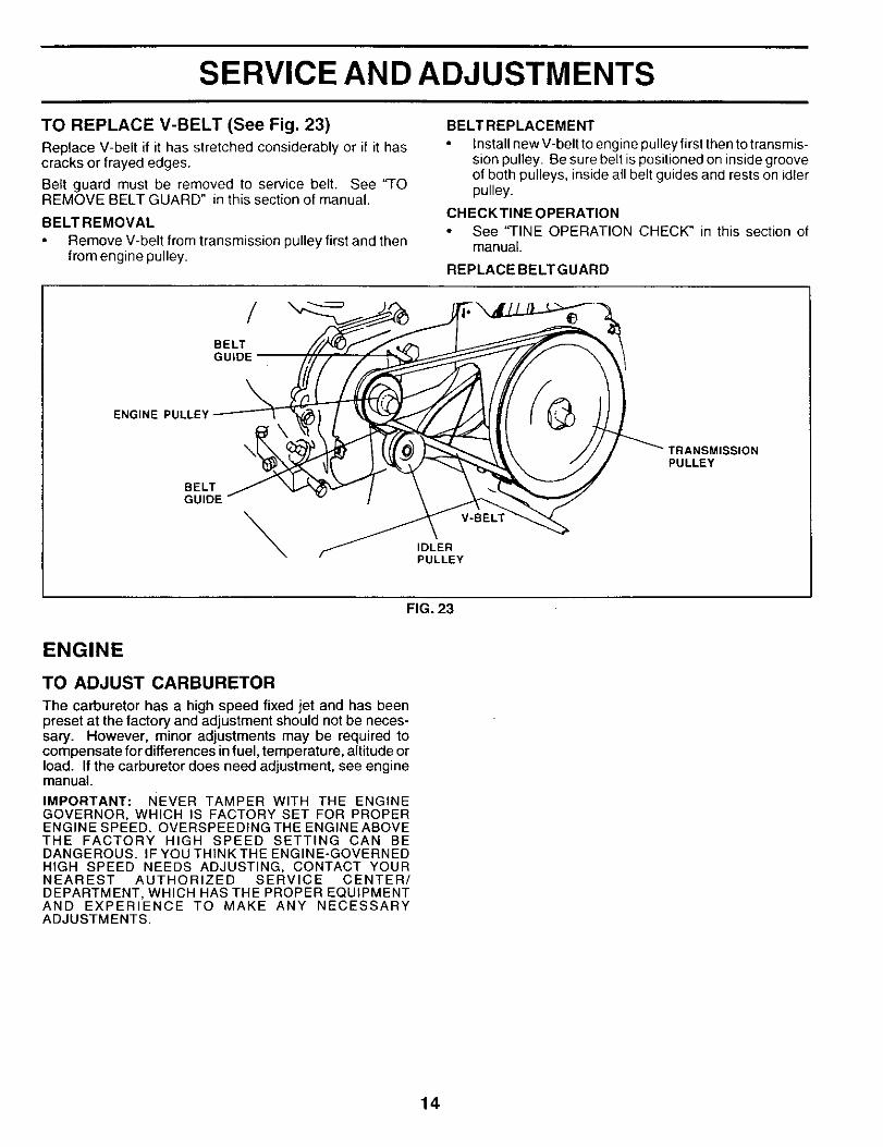
TO REPLACE V-BELT (See Fig. 23)
Replace V-belt if it has stretched considerably or if it hascracks or frayed edges.
Belt guard must be removed to service belt. See 'q'OREMOVE BELT GUARD" in this section of manual.
BELTREMOVAL
Remove V-belt from transmission pulley first and thenfrom engine pulley.
BELTREPLACEMENT
Install new V-belt to engine pulley first then to transmis-sion pulley. Be sure belt is positioned on inside grooveof both pulleys, inside all belt guides and rests on idlerpulley.
CHECKTINE OPERATIONSee "TINE OPERATION CHECK" in this section ofmanual.
REPLACE BELTGUARD
BELT
\ENGINE PULLEY
BELTGUIDE
\ V-BELT
IDLERPULLEY
rRANSMISSIONPULLEY
FIG. 23
ENGINE
TO ADJUST CARBURETOR
The carburetor has a high speed fixed jet and has beenpreset at the factory and adjustment should not be neces-sary. However, minor adjustments may be required tocompensate for differences in fuel, temperature, altitude orload. If the carburetor does need adjustment, see enginemanual.
IMPORTANT: NEVER TAMPER WITH THE ENGINEGOVERNOR, WHICH IS FACTORY SET FOR PROPERENGINE SPEED. OVERSPEEDING THE ENGINE ABOVETHE FACTORY HIGH SPEED SETTING CAN BEDANGEROUS. IF YOU THINK THE ENGINE-GOVERNEDHIGH SPEED NEEDS ADJUSTING, CONTACT YOURNEAREST AUTHORIZED SERVICE CENTER/DEPARTMENT, WHICH HAS THE PROPER EQUIPMENTAND EXPERIENCE TO MAKE ANY NECESSARYADJUSTMENTS.
14
STORAGE
Immediately prepare your tiller for storage at the end of the ENGINE OILseason or if the unit will not be used for 30 days or more.
CAUTION: Never store the tiller withgasoline in the tank inside a buildingwhere fumes may reach an open flameor spark. Allow the engine to coolbefore storing in any enclosure.
TILLERClean entire tiller (See "CLEANING" in the CustomerResponsibilities section of this manual).Inspect and replace belts, if necessary (See belt re-placement instructions in the Service and Adjustmentssection of this manual).
Lubricate as shown in the Customer Responsibilitiessection of this manual.
Be sure that all nuts, bolts and screws are securelyfastened. Inspect moving parts for damage, breakageand wear. Replace if necessary.Touch up all rusted or chipped paint surfaces; sandlightly before painting.
ENGINE
FUEL SYSTEM
IMPORTANT: IT IS IMPORTANT TO PREVENT GUMDEPOSITS FROM FORMING IN ESSENTIAL FUEL SYSTEMPARTS SUCH AS THE CARBURETOR, FUEL FILTER,FUEL HOSE, OR TANK DURING STORAGE. ALSO,EXPERIENCE INDICATES THAT ALCOHOL BLENDEDFUELS (CALLED GASOHOL OR USING ETHANOL ORMETHANOL) CAN ATTRACT MOISTURE WHICH LEADSTO SEPARATION AND FORMATION OF ACIDS DURINGSTORAGE. ACIDIC GAS CAN DAMAGE THE FUELSYSTEM OF AN ENGINE WHILE IN STORAGE.
• Drain the fuel tank.
Start the engine and let it run until the fuel lines andcarburetor are empty.
• Never use engine or carburetor cleaner products in thefuel tank or permanent damage may occur.Use fresh fuel next season.
NOTE: Fuel stabilizer is an acceptable alternative inminimizing the formation of fuel gum deposits during stor-age. Add stabilizer to gasoline in fuel tank or storagecontainer. Always follow the mix ratio found on stabilizercontainer. Run engine at least 10 minutes after addingstabilizer to allow the stabilizer to reach the carburetor. Donot drain the gas tank and carburetor if using fuel stabilizer.
D rain oil (with engine warm) and replace with clean oil. (See"ENGINE" in the Customer Responsibilities section of thismanual).
CYLINDER(S)Remove spark plug.
• Pour1 ounce (29 ml) of oil through spark plug hole intocylinder.Pull starter handle slowly several times to distribute oil.Replace with new spark plug.
OTHERDo not store gasoline from one season to another.Replace your gasoline can if your can starts to rust.Rust and/or dirt in your gasoline will cause problems.
• If possible, store your unit indoors and cover it to giveprotection from dust and dirt.Coveryour unit with a suitable protective coverthat doesnot retain moisture. Do net use plastic. Plastic cannotbreathe which allows condensation to form and willcause your unit to rust.
IMPORTANT: NEVER COVER TILLER WHILE ENGINEAND EXHAUST AREAS ARE STILL WARM.
15
TROUBLESHOOTING POINTS
CAUSE CORRECTIONPROBLEM
Will not start
Hard to start
Loss of power
Engine overheats
Excessive bounce/
difficult handling
Soil balls up or clumps
Engine runs but tillerwon't move
Engine runs but laborswhen tilling
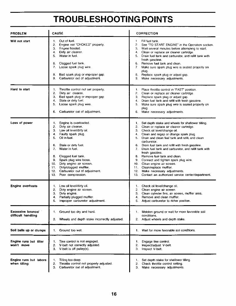
1. Out of fuel.
2. Engine not "CHOKED" properly.3. Engine flooded.4. Dirty air cleaner.5. Water in fuel.
6. CLogged fuel tank.7. Loose spark plug wire
8. Bad spark plug or improper gap9. Carburetor out of adjustment.
1. Throttle control not set properly.2. Dirty air cleaner.3. Bad spark plug or improper gap.4. Stale or dirty fuel.5. Loose spark plug wire.
6. Carburetor out of adjustment.
1. Engine is overloaded.2. Dirty air cleaner.3. Low oil level/dirty oil.4. Faulty spark plug.5. Oil in fuel.
6. Stale or dirty fuel.7. Water in fuel.
8. Clogged fuel tank.9. Spark plug wire loose.
t0. Dirty engine air screen.11. Dirty/clogged muffler.12.13.
Carburetor out of adjustment.Poor compression.
1. Low oil level/dirty oil.2. Dirty engine air screen.3. Dirty engine.4. Partially plugged muffler.5. Improper carburetor adjustment.
"l. Ground too dry and hard.
2. Wheels and depth stake incorrectly adjusted.
1. Ground too wet.
1. Tine control is not engaged.2. V-belt not correctly adjusted.3. V-belt is off pulley(s).
1. Tilling toodeep.2. Throttle control not properly adjusted.3. Carburetor out of adjustment.
1 Fill fuel tank.
2. See "TO START ENGINE" in the Operation section.3. Wait several minutes before attempting to start.4. Clean or replace air cleaner carthdge5. Drain fuel tank and carburetor, and refill tank with
fresh gasoline.6. Remove fuel tank and clean.
7. Make sure spark plug wire is seated propedy onplug.
8. Replace spark plug or adjust gap.9. Make necessary adjustments.
1. Place throttle control in "FAST" position.2. Clean or replace air cleaner cartridge.3 Replace spark plug or adjust gap.4. Drain fuel tank and refill with fresh gasoline.5. Make sure spark plug wire is seated properly on
plug.6. Make necessary adjustments.
1. Set depth stake and wheels for shallower tilling.2. Clean or replace air cleaner cartndge.3+ Check oil level/change oil.4. Clean and regap or change spark plug.5. Drain and clean fuel tank and refill, and clean
carburetor.
6. Drain fuel tank and refill with fresh gasoline.7. Drain fuel tank and carburetor, and refill tank with
fresh gasoline.8. Remove fuel tank and clean.
9. Connect and tighten spark plug wire.10. Clean engine air screen.11. Clean/replace muffler.12. Make necessary adjustments.13. Contact an authorized service center/department.
1. Check oil level/change oil+2. Clean engine air screen.3. Clean cylinder fins, air screen, muffler area.4. Remove and clean muffler.
5. Adjust carburetor to dcher position.
1. Moisten ground or wait for more favorable soilconditions.
2. Adjust wheels and depth stake.
1. Wait for more favorable soLIconditions.
1, Engage tine control.2. Inspect/adjust V-belt,3. Inspect V-belt.
1. Set depth stake for shallower tilling.2. Check throttle control setting.3+ Make necessary adjustments.
16
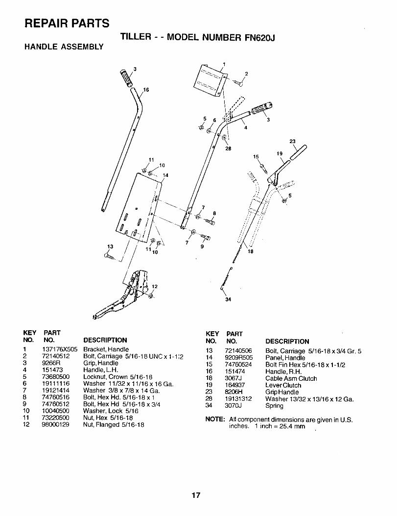
REPAIR PARTSTILLER - - MODEL NUMBER FN620J
HANDLE ASSEMBLY
3
16
KEY PARTNO. NO.
1 137176X5052 721405123 9266R4 1514735 736805006 191111167 191214148 747605169 7476051210 1004050011 7322050012 98000129
5 3
13
34
DESCRIPTIONKEY PARTNO. NO.
Bracket, Handle 13 72140506Bolt, Carriage 5/16-18 UNC x 1-1 ;2 14 9209R505Grip, Handle 15 74760524Handle, L.H. 16 151474Locknut, Crown 5/16-18 18 3067JWasher 11/32x11/16x16Ga. 19 164937Washer 3/8 x 7/8 x 14 Ga. 23 8206HBolt, Hex Hd. 5/16-18 x 1 28 19131312Bolt, Hex Hd 5/16-18 x 3/4 34 3070JWasher, Lock 5/16Nut, Hex 5/16-18Nut, Flanged 5/16-18
DESCRIPTION
Bolt, Carriage 5/16-18 x 3/4 Gr. 5Panel, HandleBolt Fin Hex 5/16-18 x 1-1/2Handle, R.H.Cable Asm ClutchLever ClutchGdpHandleWasher 13/32 x 13/16 x 12 Ga.Spring
NOTE: All component dimensions are given in U.S.inches. 1 inch = 25.4 mm
17
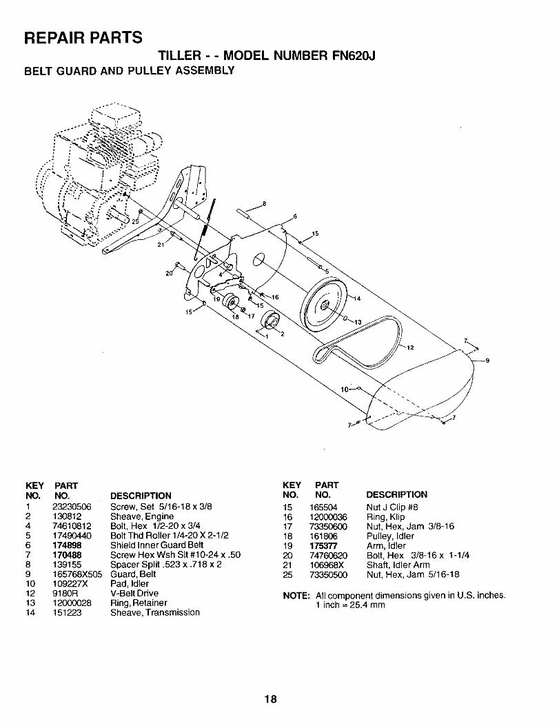
REPAIR PARTSTILLER - - MODEL NUMBER FN620J
BELT GUARD AND PULLEY ASSEMBLY
KEYNO.1245678910121314
PARTNO.
232305061308127461081217490440174898170488139155165768X505109227X9180R12000028151223
DESCRIPTIONScrew, Set 5/16-18 x 3/8Sheave, EngineBolt, Hex 1/2-20 x 3/4Bolt Thd Roller 1/4-20 X 2-1/2Shield Inner Guard BeltScrew Hex Wsh Sit #10-24 x .50Spacer Split .523 x .718 x 2Guard, BeltPad, IdlerV-Belt DriveRing, RetainerSheave, Transmission
KEY PARTNO. NO. DESCRIPTION
15 165504 Nut J Clip #816 12000036 Ring, Klip17 73350600 Nut, Hex, Jam 3/8-1618 161806 Pulley, Idler19 175377 Arm, Idler20 74760620 Bolt, Hex 3/8-16x 1-1/421 106968X Shaft, Idler Arm25 73350500 Nut, Hex, Jam 5/16-18
NOTE: All component dimensions given in U.S. inches.1 inch = 25.4 mm
18
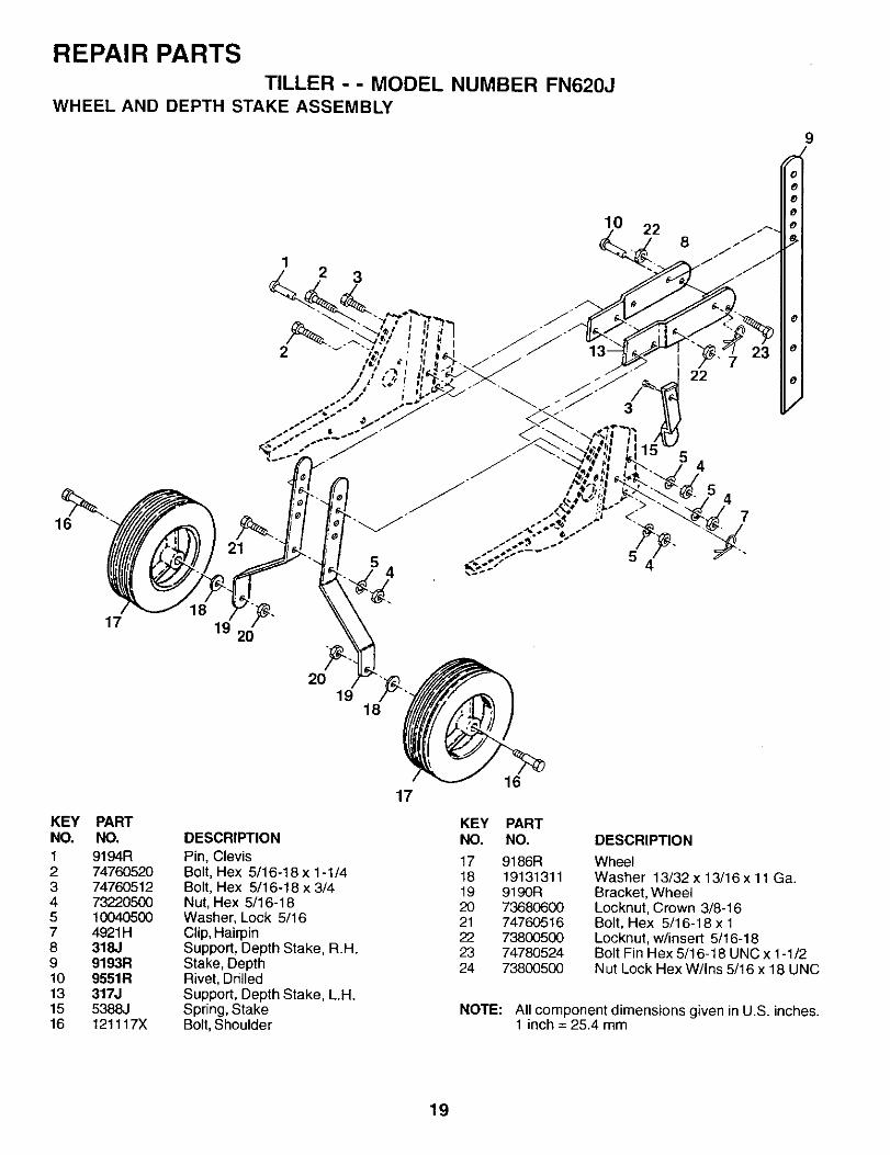
REPAIR PARTSTILLER - - MODEL NUMBER FN620J
WHEEL AND DEPTH STAKE ASSEMBLY
9
16
12
21
3
10 22
22
4
47
17 19 _"20
20 ""I
1918
KEYNO.1234578910131516
PARTNO. DESCRIPTION
9194R Pin, Clevis74760520 Bolt, Hex 5/16-18 x 1-1/474760512 Bolt, Hex 5/16-18 x 3/473220500 Nut, Hex 5/16-1810040500 Washer, Lock 5/164921H Clip, Hairpin318.1 Support, Depth Stake, R.H.9193R Stake, Depth9551R Rivet, Drilled317J Support, Depth Stake, L.H.5388..I Spring, Stake121117X Bolt, Shoulder
1716
KEY PARTNO. NO.
17 9186R18 1913131119 9190R20 7368060021 7476051622 7380050023 7478052424 73800500
DESCRIPTION
WheelWasher 13/32 x 13/16 x 11 Ga.Bracket, WheelLocknut, Crown 3/8-16Bolt, Hex 5/16-18 x 1Locknut, w/insert 5/16-18Bolt Fin Hex 5/16-18 UNC x 1-1/2Nut Lock Hex W/Ins 5/16 x 18 UNC
NOTE: All component dimensions given in U.S. inches.1 inch = 25.4 mm
19
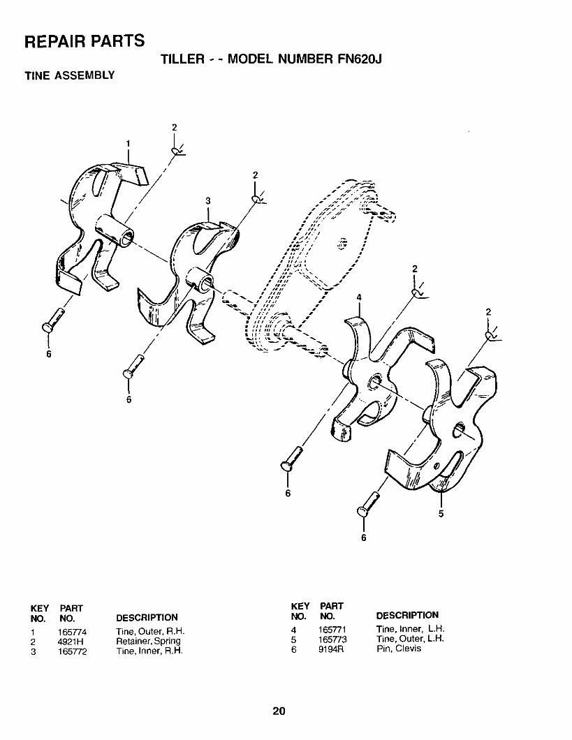
REPAIR PARTS
TINE ASSEMBLY
TILLER - - MODEL NUMBER FN620J
6/
6
I6
6
KEYNO.
123
PARTNO.
1657744921H165772
DESCRIPTION
Tine, Outer, R.H.Retainer, SpringTine, Inner, R.H
KEYNO.
456
PARTNO.
1657711657739194R
DESCRIPTION
Tine, Inner, L.H.Tine, Outer, L.H.Pin, Clevis
20
REPAIR PARTS
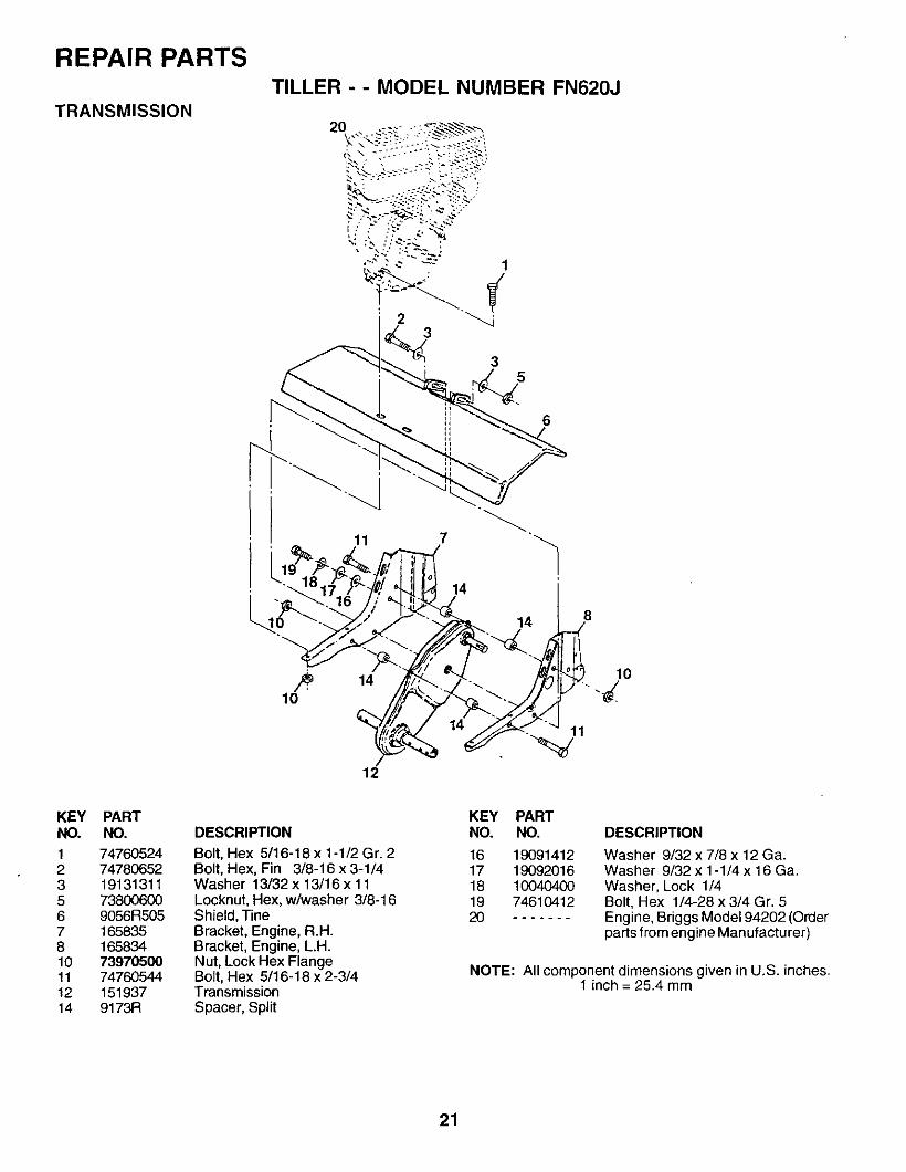
TRANSMISSION
TILLER - - MODEL NUMBER FN620J
20
1
3
35
10
11
14
12
14
14
11
lO
KEY PARTNO. NO.
1 747605242 747806523 191313115 738OO60O6 9056R5057 1658358 16583410 7397050011 74760544!2 15193714 9173R
DESCRIPTION
Bolt, Hex 5/16-18 x 1-1/2 Gr. 2Bolt, Hex, Fin 3/8-16 x 3-1/4Washer 13/32 x 13/16 x 11Locknut, Hex, w/washer 3/8-16Shield, TineBracket, Engine, R.H.Bracket, Engine, L.H.Nut, Lock Hex FlangeBolt, Hex 5/16-18 x 2-3/4TransmissionSpacer, Split
KEY PARTNO. NO.
16 1909141217 1909201618 1004040019 746104122O
DESCRIPTION
Washer 9/32 x 7/8 x 12 Ga.Washer 9/32 x 1-1/4 x 16 Ga.Washer, Lock 1/4Bolt, Hex 1/4-28 x 3/4 Gr. 5Engine, Briggs Model 94202 (Orderparts from engine Manufacturer)
NOTE: All component dimensions given in U,S. inches.1 inch = 25.4 mm
21
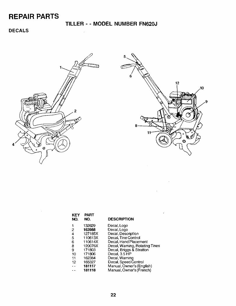
REPAIR PARTSTILLER - - MODEL NUMBER FN620J
DECALS
12
/10
j'
KEYNO.
1245689101112
PARTNO.
t 32629163988127185X110613X110614X120076X171803171806162384165327181117181118
DESCRIPTION
Decal, LogoDecal, LogoDecal, DescriptionDecal, Tine ControlDecal, Hand PlacementDecal, Warning, Rotating TinesDecal, Briggs & StrattonDecal, 3,5 HPDecal, WarningDecal, Speed ControlManual, Owner's (English)Manual, Owner's (French)
22
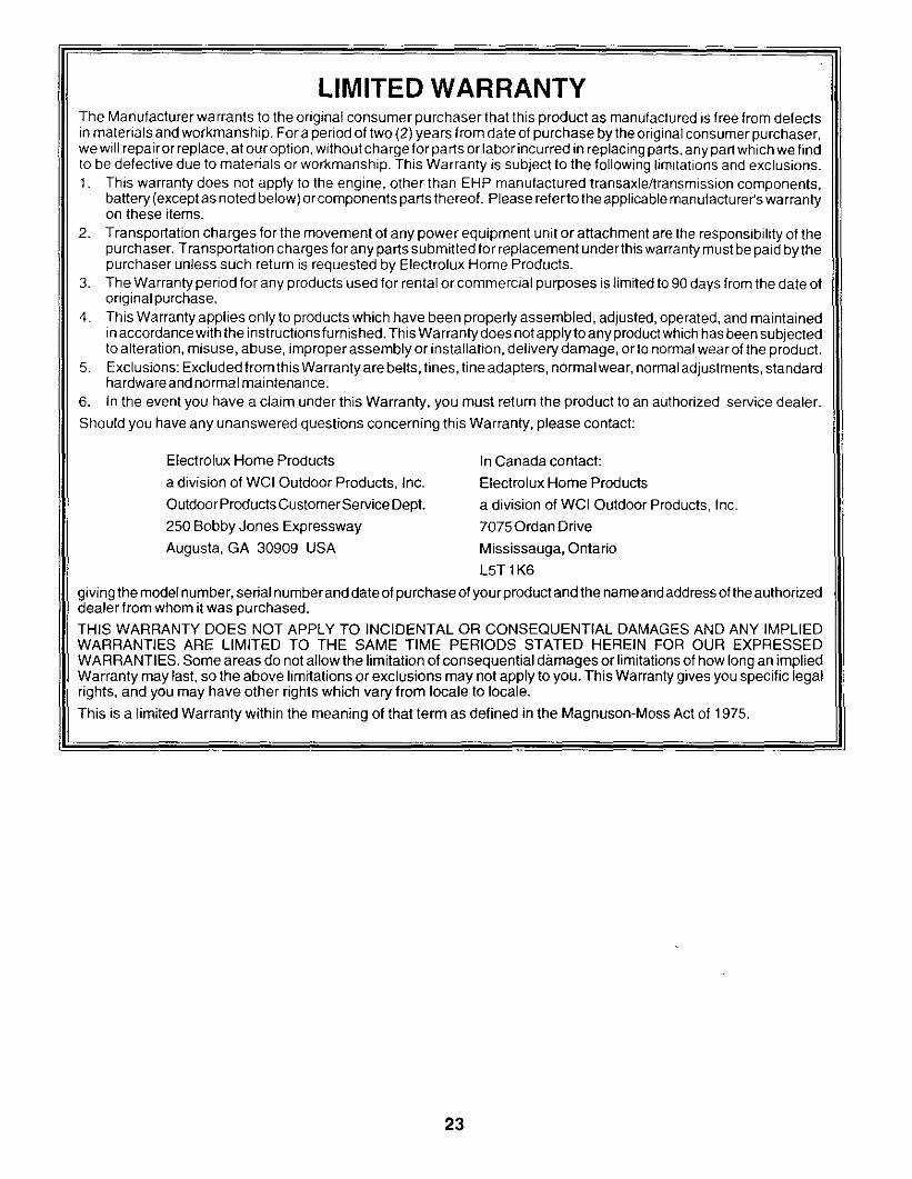
LIMITED WARRANTYThe Manufacturer warrants to the original consumer purchaser that this product as manufactured is free from defectsin materials and workmanship. For a period of two (2) years from date of purchase by the original consumer purchaser,we will repair or replace, at our option, without charge for parts or labor incurred in replacing parts, any part which we findto be defective due to materials or workmanship. This Warranty is subject to the following limitations and exclusions.1. This warranty does not apply to the engine, other than EHP manufactured transaxle/transmission components,
battery (except as noted below) or components parts thereof. Please referto the applicable manufacturer's warrantyon these items.
2. Transportation charges for the movement of any power equipment unit or attachment are the responsibility of thepurchaser. Transportation charges for any parts submitted for replacement under this warranty must be paid by thepurchaser unless such return is requested by Electrolux Home Products.
3. The Warranty period for any products used for rental or commercial purposes is limited to 90 days from the date oforiginal purchase.
4. This Warranty applies only to products which have been properly assembled, adjusted, operated, and maintainedin accordance with the instructions fu rnished. This Warranty does not apply to any product which has been subjectedto alteration, misuse, abuse, improper assembly or installation, delivery damage, or to normal wear of the product.
5. Exclusions: Excluded from this Warranty are belts, tines, tine adapters, normal wear, normal adjustments, standardhardware and normal maintenance.
6. In the event you have a claim under this Warranty, you must return the product to an authorized service dealer.
Should you have any unanswered questions concerning this Warranty, please contact:
Electrolux Home Products
a division of WCI Outdoor Products, Inc.
Outdoor Products Customer Service Dept.
250 Bobby Jones Expressway
Augusta, GA 30909 USA
In Canada contact:
Electrolux Home Products
a division of WCI Outdoor Products, Inc.
7075 Ordan Drive
Mississauga, OntarioLhT 1K6
giving the model number, serial number and date of purchase of your product and the name and address of the authorizeddealer from whom it was purchased.THIS WARRANTY DOES NOT APPLY TO INCIDENTAL OR CONSEQUENTIAL DAMAGES AND ANY IMPLIEDWARRANTIES ARE LIMITED TO THE SAME TIME PERIODS STATED HEREIN FOR OUR EXPRESSEDWAR RANTIES. Some areas do net allow the limitation of consequential damages or limitations of how long an impliedWarranty may last, so the above limitations or exclusions may not apply to you. This Warranty gives you specific legalrights, and you may have other rights which vary from locale to locale.
This is a limited Warranty within the meaning of that term as defined in the Magnuson-Moss Act of 1975.
23

Rally